EP1564005B1 - Tape supply cartridge - Google Patents
Tape supply cartridgeDownload PDFInfo
- Publication number
- EP1564005B1 EP1564005B1EP05003912AEP05003912AEP1564005B1EP 1564005 B1EP1564005 B1EP 1564005B1EP 05003912 AEP05003912 AEP 05003912AEP 05003912 AEP05003912 AEP 05003912AEP 1564005 B1EP1564005 B1EP 1564005B1
- Authority
- EP
- European Patent Office
- Prior art keywords
- tape
- cartridge
- guide
- tape supply
- ribbon
- Prior art date
- Legal status (The legal status is an assumption and is not a legal conclusion. Google has not performed a legal analysis and makes no representation as to the accuracy of the status listed.)
- Expired - Lifetime
Links
- 238000000576coating methodMethods0.000description13
- 239000011248coating agentSubstances0.000description11
- 238000005520cutting processMethods0.000description11
- 230000007246mechanismEffects0.000description10
- GWEVSGVZZGPLCZ-UHFFFAOYSA-NTitan oxideChemical compoundO=[Ti]=OGWEVSGVZZGPLCZ-UHFFFAOYSA-N0.000description8
- 239000010410layerSubstances0.000description8
- 230000004888barrier functionEffects0.000description5
- 230000037361pathwayEffects0.000description5
- 238000002372labellingMethods0.000description4
- 239000000123paperSubstances0.000description4
- 239000000945fillerSubstances0.000description3
- 239000000853adhesiveSubstances0.000description2
- 230000001070adhesive effectEffects0.000description2
- 230000006872improvementEffects0.000description2
- 230000013011matingEffects0.000description2
- 229920001225polyester resinPolymers0.000description2
- 239000004645polyester resinSubstances0.000description2
- 229920000139polyethylene terephthalatePolymers0.000description2
- 239000005020polyethylene terephthalateSubstances0.000description2
- 239000000126substanceSubstances0.000description2
- 229920002799BoPETPolymers0.000description1
- 239000004698PolyethyleneSubstances0.000description1
- 239000003522acrylic cementSubstances0.000description1
- 239000012790adhesive layerSubstances0.000description1
- 238000004132cross linkingMethods0.000description1
- 238000002845discolorationMethods0.000description1
- 230000005484gravityEffects0.000description1
- 238000010438heat treatmentMethods0.000description1
- 238000003780insertionMethods0.000description1
- 230000037431insertionEffects0.000description1
- 239000002655kraft paperSubstances0.000description1
- 239000003209petroleum derivativeSubstances0.000description1
- 229920000728polyesterPolymers0.000description1
- -1polyethylenePolymers0.000description1
- 229920000573polyethylenePolymers0.000description1
- 230000005855radiationEffects0.000description1
- 238000000926separation methodMethods0.000description1
- 229910052710siliconInorganic materials0.000description1
- 239000010703siliconSubstances0.000description1
- 239000004408titanium dioxideSubstances0.000description1
Images


Classifications
- B—PERFORMING OPERATIONS; TRANSPORTING
- B41—PRINTING; LINING MACHINES; TYPEWRITERS; STAMPS
- B41J—TYPEWRITERS; SELECTIVE PRINTING MECHANISMS, i.e. MECHANISMS PRINTING OTHERWISE THAN FROM A FORME; CORRECTION OF TYPOGRAPHICAL ERRORS
- B41J15/00—Devices or arrangements of selective printing mechanisms, e.g. ink-jet printers or thermal printers, specially adapted for supporting or handling copy material in continuous form, e.g. webs
- B41J15/04—Supporting, feeding, or guiding devices; Mountings for web rolls or spindles
- B41J15/044—Cassettes or cartridges containing continuous copy material, tape, for setting into printing devices
- B—PERFORMING OPERATIONS; TRANSPORTING
- B41—PRINTING; LINING MACHINES; TYPEWRITERS; STAMPS
- B41J—TYPEWRITERS; SELECTIVE PRINTING MECHANISMS, i.e. MECHANISMS PRINTING OTHERWISE THAN FROM A FORME; CORRECTION OF TYPOGRAPHICAL ERRORS
- B41J15/00—Devices or arrangements of selective printing mechanisms, e.g. ink-jet printers or thermal printers, specially adapted for supporting or handling copy material in continuous form, e.g. webs
- B41J15/04—Supporting, feeding, or guiding devices; Mountings for web rolls or spindles
- B—PERFORMING OPERATIONS; TRANSPORTING
- B41—PRINTING; LINING MACHINES; TYPEWRITERS; STAMPS
- B41J—TYPEWRITERS; SELECTIVE PRINTING MECHANISMS, i.e. MECHANISMS PRINTING OTHERWISE THAN FROM A FORME; CORRECTION OF TYPOGRAPHICAL ERRORS
- B41J17/00—Mechanisms for manipulating page-width impression-transfer material, e.g. carbon paper
- B41J17/02—Feeding mechanisms
- B—PERFORMING OPERATIONS; TRANSPORTING
- B41—PRINTING; LINING MACHINES; TYPEWRITERS; STAMPS
- B41J—TYPEWRITERS; SELECTIVE PRINTING MECHANISMS, i.e. MECHANISMS PRINTING OTHERWISE THAN FROM A FORME; CORRECTION OF TYPOGRAPHICAL ERRORS
- B41J3/00—Typewriters or selective printing or marking mechanisms characterised by the purpose for which they are constructed
- B41J3/407—Typewriters or selective printing or marking mechanisms characterised by the purpose for which they are constructed for marking on special material
- B41J3/4075—Tape printers; Label printers
- B—PERFORMING OPERATIONS; TRANSPORTING
- B41—PRINTING; LINING MACHINES; TYPEWRITERS; STAMPS
- B41J—TYPEWRITERS; SELECTIVE PRINTING MECHANISMS, i.e. MECHANISMS PRINTING OTHERWISE THAN FROM A FORME; CORRECTION OF TYPOGRAPHICAL ERRORS
- B41J31/00—Ink ribbons; Renovating or testing ink ribbons
- B41J31/12—Ink ribbons having arrangements to prevent undesired contact between the impression-transfer material and machine parts or other articles
- B—PERFORMING OPERATIONS; TRANSPORTING
- B41—PRINTING; LINING MACHINES; TYPEWRITERS; STAMPS
- B41J—TYPEWRITERS; SELECTIVE PRINTING MECHANISMS, i.e. MECHANISMS PRINTING OTHERWISE THAN FROM A FORME; CORRECTION OF TYPOGRAPHICAL ERRORS
- B41J35/00—Other apparatus or arrangements associated with, or incorporated in, ink-ribbon mechanisms
- B41J35/04—Ink-ribbon guides
Definitions
- the present inventionrelates generally to a tape supply cartridge and more specifically to a tape supply cartridge for use in a labeler for printing indicia on such tape for selective application to a desired medium. Still more specifically, the present invention relates to a tape supply cartridge of the type commonly referred to as a non-laminated, thermal transfer tape supply cartridge.
- cartridgesare designed to be used in labeling machines or printers which have a cartridge receiving cavity for receiving the cartridge in an operative position, a thermal print head and an associated platen roller which is selectively moveable toward and away from the print head, with the tape positioned therebetween, for the purpose of forming an image on, or transferring an image to, the tape.
- labeling machines or printersalso include a means for advancing the tape past the print head and for advancing the various other spooled components through apparatus.
- the present inventionrelates to a tape supply cartridge for use in a labeling machine or other printer. More specifically, the tape supply cartridge of the present invention includes the features of claim 1.
- Another object of the present inventionis to provide an improved tape guide means for such a cartridge.
- the present inventionrelates to a tape supply cartridge and more specifically to what is commonly referred to as a non-laminated tape supply cartridge.
- Tape supply cartridges of this typeare designed for use in labelers or printers which include a cartridge receiving cavity, a print head 7 ( Figure 6 ), a platen roller 8 moveable toward and away from the print head 7 to define printing and non-printing positions, a means for advancing the tape and ribbon through the cartridge and past the print station and a means for selectively cutting the tape after printing.
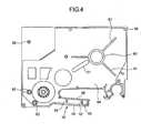
- the cartridge 10includes a cartridge top 11 and a cartridge bottom 12. When assembled, the top 11 and bottom 12 are secured together to form the cartridge 10 which house the tape supply 13, a ribbon supply spool 23 and a ribbon take-up spool 17.
- the cartridgealso includes a tape exit end 14, a tape exit slot 15 provided at the exit end 14 and a print head cavity or recessed area 16 to accommodate a print head when the cartridge is inserted into the printer.
- the print head cavityis defined on one side by a tape/ribbon guide arm 38 for guiding the tape and ribbon to the print station.
- the areas 18 and 19 in the cartridge top 11 and bottom 12define areas to accommodate the ink ribbon supply spool 23 and the ink ribbon take-up spool 17, respectively.
- a tape advance roller 20is provided at the tape exit end of the cartridge.
- the roller 20is a driven feed roller having internal splines, ribs or other means for mating with a drive shaft of the printer.
- a latching rib 21is provided on one side of the cartridge for engagement by a latch member (not shown) on the printer to secure the cartridge within the printer when the cartridge is inserted into the cartridge cavity.
- a second latching rib 22( Figure 3 ) is provided on the opposite side of the cartridge bottom 12 for engagement with a second printer latch member (not shown).
- An elongated tape guide wall 30extends from an inner portion of the side wall 24 to a tape passage slot 31 between the pair of spaced wall sections 32,32.
- the guide wall 30extends upwardly from the bottom wall 25 at substantially right angles and ensures that the tape from the tape supply 13 is properly and accurately guided from the tape spool 13 to the tape passage 31.
- a pair of tape guide/posts 34,34are integrally formed with the bottom wall 25 and extend upwardly therefrom at right angles.
- the tape guide/posts 34,34support corresponding rollers 35,35 for guiding the tape around the ribbon supply spool 23 which is rotatably mounted on the support post 36.
- the rollers 35,35have a generally cylindrical configuration and a cylindrical interior opening slightly greater than the exterior dimension of the posts 34,34. This enables the tape to be freely pulled and advanced around the posts 34,34 by the tape advancement means.
- a barrier member 33is positioned between the rollers 35,35 to prevent the tape from being inadvertently or intentionally routed between the rollers 35,35.
- the member 33forces the tape to have only a single pathway around the outside of the rollers 35,35.
- the barrieris provided with a generally trapezoidal cross-sectional configuration.
- the portion of the cartridge bottom 12 defining the tape/ribbon guide arm 38includes an outer side wall 39 and an inner side wall 40 which are substantially parallel to one another.
- Each of the walls 39 and 40are of approximately equal height measured from the bottom wall 25 and are taller than the major portion of the side wall 24 extending around the periphery of the cartridge bottom.
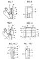
- a tape/ribbon separation wall or barrierPositioned approximately midway between the walls 39 and 40 is a tape/ribbon separation wall or barrier defined by a pair of posts 41,41 and a wall section 42 integrally joined with the posts 41,41 and extending therebetween.
- posts 41,41are taller than the wall sections 39 and 40 and the wall section 42 is significantly shorter than either the posts 41,41 or the walls 39, 40.
- the upper ends of the posts 41,41are provided with a recessed portion 44 which is designed to accommodate an upper tape guide member 45 integrally formed with a corresponding portion of the cartridge top 11 defining the tape/ribbon guide arm 38.
- This portion of the cartridge top 11includes a pair of short wall sections 46 and 47 designed to mate with the wall sections 39 and 40 when the cartridge is assembled.
- the print head recessed area 16 as shown best in Figures 1-6is defined on one side by the inner wall sections 40 and 68 of the cartridge bottom and tops and on the opposite sides by the wall sections 86, 88 and 89.
- the walls sections 86, 88 and 89are integrally formed with the bottom wall 25 and extend upwardly therefrom at substantially right angles.
- the wall sections 86, 88 and 89are joined to one another at their side edges and form a generally continuous wall which, together with the wall section 40, defines the cavity 16.
- the ends of the wall sections 86, 40are spaced from one another as shown to provide an opening through which the platen roller 8 ( Figure 6 ) may move relative to the print head 7 to define the print station.
- the cartridge top 11 as shown in Figure 4includes a top wall 64 and a side wall 65 extending around a substantial portion of the periphery of the cartridge top 11.
- a portion of the cartridge topcorresponds to the tape/ribbon guide arm 38.
- This portionincludes an outer edge 66 and an inner edge 68 substantially parallel to one another and corresponding to the edges 39 and 40, respectively, of the cartridge bottom 12.
- the wall portions 66 and 68are shorter than the remainder of the side wall 65.
- the inside of the cartridge top 11comprises elements corresponding to various elements in the cartridge bottom 12 including a plurality of connection posts 56 positioned throughout the top wall 64. These connection posts 56 are designed for insertion into the corresponding connection holes 55 in the cartridge bottom to fix the top 11 to the bottom 12.
- the cartridge topalso includes a generally circular rib 60 and a plurality of ribs 61 extending radially outwardly from the rib 60.
- the circular rib 60is aligned with the hub 26 ( Figure 3 ) and has an internal circular dimension approximating the outer circular dimension of the hub 26 so that when the cartridge is assembled, the upper edge of the hub 26 seats within the circular rib 60.
- the tape 13 to be used in the cartridge of the present inventionis intended to be a so-called non-laminated tape which includes a print receiving tape layer and a release layer.
- the print receiving tape layercomprises the base film 92 and the coating 93 applied thereto.
- the base film 92is a polyethylene-terephthalate (PET) film.
- PETpolyethylene-terephthalate
- the base film 92is provided with an inert filler such as titanium dioxide TiO 2 ) to provide the film with a white color. Because of the presence of this TiO 2 , the specific gravity of the film 92 is preferably greater than about 1.1, more preferably greater than about 1.2 and most preferably greater than about 1.3.
- an inert fillersuch as TiO 2
- the film 92is about 2 mils (0.002 inches) thick.
- a film of this type preferably used to make the tape 13 of the present inventionis a PET film manufactured by Dupont.
- a heat activatable polyester resin coating 93is applied to the print receiving surface of the film 92.
- This polyester resin coating 93is a relatively thin layer and functions primarily to receive the printed image from the transfer tape. Accordingly, the chemistry of the coating 92 must be compatible with that of the transfer ribbon. Further, it is preferable for both the coating 93 and the base film 92 to be compatible (i.e., both are polyesters).
- an adhesive layer 94is applied to the opposite surface of the film 92.
- the adhesiveis a premium, self cross linking acrylic adhesive which is resistant to UV radiation as well as a variety of chemicals and petroleum distillates.
- the second portion of the tape 13is the release liner which is comprised of the paper base 95, an intermediate coating 96 and an outer release coating 97.
- the paper layer 95is a densified Kraft paper
- the coating 96is a coating of polyethylene
- the coating 97is a coating of silicon.
- the entire thickness of the tape 13is approximately 7 mils (0.007 inches), with the print receiving tape portion (comprised of the film 92 and the layers 93 and 94) being thinner than the release liner portion) comprised of the paper layer 95 and the coatings 96 and 97).
- the ribbon which is provided on the ribbon supply spool 23is what is referred to as a thermal transfer or heat activatable ribbon.
- the ribbonis effective to transfer an image from the ribbon to the print receiving surface of the tape. It is preferred that the tape and the ribbon in the cartridge of the present invention be compatible with one another.
- the tapehave sufficient stiffness so that when it exits the exit slot 15 and is cut by the cutting mechanism, it is stiff enough to resist moving along with the retraction of the moveable cutting member.
- stiffnessis provided by the thickness of the paper base layer 95 which, together with the coatings 96 and 97, is thicker than the print receiving portion of the tape.
- the tapeWhen the cartridge is fully assembled, the tape extends from the tape spool 13 along the tape path as shown in Figure 6 . Specifically, the tape extends from the spool 13 where it is guided by the guide wall 30 through the pathway 31 between the elements 32,32. From there, the tape extends around the guide rollers 35,35 and through the pathway 51 in the guide arm 38 between the posts 41,41 and the wall section 39. From there, it extends to and across the printing region between the print head 7 and the platen roller 8, past the advancement area between the roller 20 and the drive roller 9 of the printer and then outwardly through the exit slot 15.
Landscapes
- Impression-Transfer Materials And Handling Thereof (AREA)
- Handling Of Continuous Sheets Of Paper (AREA)
- Printers Characterized By Their Purpose (AREA)
- Packaging Of Annular Or Rod-Shaped Articles, Wearing Apparel, Cassettes, Or The Like (AREA)
- Unwinding Webs (AREA)
- Wrappers (AREA)
- Automatic Tape Cassette Changers (AREA)
- Handling Of Sheets (AREA)
Abstract
Description
- The present invention relates generally to a tape supply cartridge and more specifically to a tape supply cartridge for use in a labeler for printing indicia on such tape for selective application to a desired medium. Still more specifically, the present invention relates to a tape supply cartridge of the type commonly referred to as a non-laminated, thermal transfer tape supply cartridge.
- A great number of prior art tape supply cartridges and patents exist for use in connection with label or strip printers or the like. These cartridges provide a supply of wound printing tape to a print head for printing indicia on the tape for subsequent selective application to a desired medium. Some of these cartridges are exemplified by and disclosed in
U.S. Patent Nos. 5,188,469 ;5,350,243 ;5,653,542 ;5,813,773 ;4,927,278 ;4,983,058 and5,419,648 , among others. These cartridges are designed to be used in labeling machines or printers which have a cartridge receiving cavity for receiving the cartridge in an operative position, a thermal print head and an associated platen roller which is selectively moveable toward and away from the print head, with the tape positioned therebetween, for the purpose of forming an image on, or transferring an image to, the tape. Such labeling machines or printers also include a means for advancing the tape past the print head and for advancing the various other spooled components through apparatus. - Although the cartridges of the prior art function satisfactorily for their particular application, there is a continuing need for improvement of such cartridges. Particular features for which there is a continuing need for improvement include the ability of the cartridge to accommodate different sizes and widths of tape relative to a transfer ribbon, the ability of the cartridge to guide the tape through the cartridge while ensuring that proper tape resistance is achieved and the ability of the cartridge to minimize jamming of the tape at the cutting station, among others. Accordingly, there is a need for an improved tape supply cartridge for use in a tape printer as described above and a tape for use in such a cartridge.
- From
US 5,653,542 a tape supply cartridge according to the preamble of claim 1 can be taken. The guide means has the same height as the side walls. - The present invention relates to a tape supply cartridge for use in a labeling machine or other printer. More specifically, the tape supply cartridge of the present invention includes the features of claim 1.
- Accordingly, it is an object of the present invention to provide an improved tape supply cartridge for a labeling apparatus or printer.
- Another object of the present invention is to provide an improved tape guide means for such a cartridge.
Figure 1 is an isometric view of the tape supply cartridge in accordance with the present invention.Figure 2 is an isometric, exploded view of the tape supply cartridge of the present invention.Figure 3 is an elevational plan view of the inside of the cartridge bottom with the tape supply spool, the ribbon supply and rewind spools and various other components removed.Figure 4 is an elevational plan view of the inside of the cartridge top.Figure 5 is a elevational bottom view of the assembled cartridge.Figure 6 is an elevational view of the inside of the cartridge bottom, similar toFigure 3 , showing the tape and ribbon pathways.Figure 7 is a fragmentary view, partially in section, showing the tape exit end of the cartridge in combination with a tape cutting means.Figure 8 is an elevational, front fragmentary view of the tape exit end of the cartridge.Figure 9 is a view similar to that ofFigure 6 in combination with a second embodiment of a tape cutting means.Figure 10 is a view, partially in section, as viewed along the section line 9-9 ofFigure 3 .Figure 11a is a view, partially in section, as viewed along the section line 11-11 ofFigure 10 .Figure 11b is a view similar to that ofFigure 11a , but with the cartridge top and bottom in assembled form.Figure 12 is a view, partially in section, similar to that ofFigure 10 of an alternate embodiment.Figure 13a is a view, partially in section, as viewed along the section line 13-13 ofFigure 12 .Figure 13b is a view similar to that ofFigure 13a , but with the cartridge top and bottom in assembled form.Figure 14 is a view, partially in section, of a portion of the tape supply cartridge showing the tape supply mounted between the cartridge halves.Figure 15 is a view, partially in section, as viewed along the section line 15-15 ofFigure 3 .Figure 16 is a cross-sectional view showing the tape structure.- The present invention relates to a tape supply cartridge and more specifically to what is commonly referred to as a non-laminated tape supply cartridge. Tape supply cartridges of this type are designed for use in labelers or printers which include a cartridge receiving cavity, a print head 7 (
Figure 6 ), aplaten roller 8 moveable toward and away from theprint head 7 to define printing and non-printing positions, a means for advancing the tape and ribbon through the cartridge and past the print station and a means for selectively cutting the tape after printing. - In describing the preferred embodiment of the present invention, reference is first made to
Figures 1 and2 showing the cartridge in its fully assembled form and in an exploded form. In general, thecartridge 10 includes acartridge top 11 and acartridge bottom 12. When assembled, thetop 11 andbottom 12 are secured together to form thecartridge 10 which house thetape supply 13, aribbon supply spool 23 and a ribbon take-up spool 17. The cartridge also includes atape exit end 14, atape exit slot 15 provided at theexit end 14 and a print head cavity orrecessed area 16 to accommodate a print head when the cartridge is inserted into the printer. The print head cavity is defined on one side by a tape/ribbon guide arm 38 for guiding the tape and ribbon to the print station. Theareas cartridge top 11 andbottom 12 define areas to accommodate the inkribbon supply spool 23 and the ink ribbon take-up spool 17, respectively. Atape advance roller 20 is provided at the tape exit end of the cartridge. In the preferred embodiment, theroller 20 is a driven feed roller having internal splines, ribs or other means for mating with a drive shaft of the printer. - A
latching rib 21 is provided on one side of the cartridge for engagement by a latch member (not shown) on the printer to secure the cartridge within the printer when the cartridge is inserted into the cartridge cavity. A second latching rib 22 (Figure 3 ) is provided on the opposite side of thecartridge bottom 12 for engagement with a second printer latch member (not shown). - The interior of the
cartridge bottom 12 is illustrated best with reference toFigures 2 and3 . As shown, thecartridge bottom 12 includes abottom wall 25 and aside wall 24 extending upwardly from thebottom wall 25 at substantially right angles and extending around a substantial portion of the cartridge. Integrally formed with thebottom wall 25 is atape supply hub 26 and a plurality oftape support ribs 28 extending radially outwardly from thehub 26. Thehub 26 is a generally cylindrical structure which extends outwardly from thebottom wall 25 at substantially right angles and functions to rotatably support thehub 84 of theribbon supply spool 13. A pair of tapecontainment wall sections tape supply spool 13 in a generally circular configuration. An elongatedtape guide wall 30 extends from an inner portion of theside wall 24 to atape passage slot 31 between the pair ofspaced wall sections guide wall 30 extends upwardly from thebottom wall 25 at substantially right angles and ensures that the tape from thetape supply 13 is properly and accurately guided from thetape spool 13 to thetape passage 31. - A pair of tape guide/
posts bottom wall 25 and extend upwardly therefrom at right angles. The tape guide/posts corresponding rollers ribbon supply spool 23 which is rotatably mounted on thesupport post 36. In the preferred embodiment, therollers posts posts barrier member 33 is positioned between therollers rollers member 33 forces the tape to have only a single pathway around the outside of therollers Figure 15 , the barrier is provided with a generally trapezoidal cross-sectional configuration. - The portion of the cartridge bottom 12 defining the tape/
ribbon guide arm 38 includes anouter side wall 39 and aninner side wall 40 which are substantially parallel to one another. Each of thewalls bottom wall 25 and are taller than the major portion of theside wall 24 extending around the periphery of the cartridge bottom. Positioned approximately midway between thewalls posts wall section 42 integrally joined with theposts Figure 10 , posts 41,41 are taller than thewall sections wall section 42 is significantly shorter than either theposts walls posts portion 44 which is designed to accommodate an uppertape guide member 45 integrally formed with a corresponding portion of thecartridge top 11 defining the tape/ribbon guide arm 38. This portion of thecartridge top 11 includes a pair ofshort wall sections wall sections - The
bottom wall 25, in the area of the tape/ribbon guide arm 38 is provided with a pair of bottom tape/ribbon guide edges 48 and 49, respectively for guiding the lower edges of the tape and the ribbon at the same height through theguide arm 38. In contrast, the ribbon side of the barrier between thewall section 42 and thewall 40 is provided with a pair of guide edges for guiding the tape edge of the ribbon only. The tape side of the barrier between thewall section 42 and thewall 39 is provided with a pair of spacedtape guide members 45 for guiding the tap edge of the tape only. - When the
cartridge top 11 and bottom 12 are assembled as shown inFigure 11b , the tape/ribbon guide arm 38 defines aguide passage 50 for the ribbon and aguide passage 51 for the tape. As shown, this particular embodiment illustrated inFigures 10, 11a and 11b is designed for a cartridge in which the ribbon is wider than the tape and in which the bottom edges of the tape and the ribbon are guided by a common guide edge at the same level. In the embodiment ofFigures 11a and 11b , the tape guide edges 49 guide the bottom edges of both the tape and ribbon, while theguide edge 52 guides the top edge of the ribbon and theguide member 45 guides the top edge of the tape. - An alternate embodiment for the tape arm is illustrated in
Figures 12, 13a and 13b . The embodiment ofFigures 12, 13a and 13b is similar to that ofFigures 10, 11a and 11b except that it is designed for a supply cartridge in which the tape and the ribbon are of equal width. When assembled as shown inFigure 13b , this embodiment of the tape/ribbon guide arm defines aribbon passageway 50 andtape passageway 51 which are of equal height dimensions. As shown, when the tape/ribbon guide arm 38 is assembled, thearm 38 defines aribbon passageway 50 and atape passageway 51 of the same height. In this embodiment, bothpassageways guide edge 49 and on their tops by theguide edge 52. - The cartridge bottom further includes a plurality of connection holes 55 positioned throughout the cartridge bottom for mating with corresponding connection posts 56 from the cartridge top to retain the
cartridge top 11 and bottom 12 together when the cartridge is assembled. - After the tape and ribbon leave the
guide arm 38, they pass the print station as shown inFigure 6 . From there, the ribbon is guided around the walls defining theprint head recess 16 and the tape is guided past the tape advancement or feedroller 20. In the preferred embodiment, theguide ribs guide arm 38. - The print head recessed
area 16 as shown best inFigures 1-6 is defined on one side by theinner wall sections wall sections walls sections bottom wall 25 and extend upwardly therefrom at substantially right angles. Thewall sections wall section 40, defines thecavity 16. The ends of thewall sections Figure 6 ) may move relative to theprint head 7 to define the print station. Thewall sections wall sections wall sections edges ribbon rewind spool 17. - The
cartridge top 11 as shown inFigure 4 , includes atop wall 64 and a side wall 65 extending around a substantial portion of the periphery of thecartridge top 11. A portion of the cartridge top corresponds to the tape/ribbon guide arm 38. This portion includes anouter edge 66 and aninner edge 68 substantially parallel to one another and corresponding to theedges cartridge bottom 12. In the preferred embodiment, thewall portions - The inside of the
cartridge top 11 comprises elements corresponding to various elements in the cartridge bottom 12 including a plurality of connection posts 56 positioned throughout thetop wall 64. These connection posts 56 are designed for insertion into the corresponding connection holes 55 in the cartridge bottom to fix the top 11 to the bottom 12. The cartridge top also includes a generallycircular rib 60 and a plurality ofribs 61 extending radially outwardly from therib 60. Thecircular rib 60 is aligned with the hub 26 (Figure 3 ) and has an internal circular dimension approximating the outer circular dimension of thehub 26 so that when the cartridge is assembled, the upper edge of thehub 26 seats within thecircular rib 60. Theribs 61, like theribs 28 in the cartridge bottom, function to support the spool oftape 11 in a vertical direction relative to the cartridge top and bottom. Thecartridge top 11 also includes a pair ofpost receiving holes Figure 15 . - The bottom side of the cartridge, as illustrated best in
Figure 5 , includes anopening 69 aligned with theinternal hub 26 and a recessedarea 70 in a corner of the cartridge bottom to accommodate a plurality ofcartridge detecting holes 71. Theholes 71 are aligned with one or more plunger switches associated with the printer for the purpose of providing the printer with information regarding the characteristics of the tape within the cartridge such as tape width, whether it is laminated or non-laminated, etc. The cartridge bottom also includes anopening 72 through which a ribbon rewind shaft from the printer extends to interface with and rotate theribbon rewind spool 17. Atape advance opening 74 is provided near the tape exit end of the cartridge and is designed to provide an interface between a tape advancement shaft in the printer and thetape advancement spool 20. - As illustrated best in
Figures 7 and 8 , thetape exit end 14 includes a generallyplanar surface 75, theshoulder portion 76 and the tape exit slot oropening 15. Preferably, theplanar surface 75 extends from theshoulder 76, past theslot 15 and to the uppermost end of the cartridge. In the preferred embodiment, the substantiallyplanar surface 75 and theshoulder 76 form a recessed area to accommodate one embodiment of a stationarytape cutoff member 78 of the printer. As shown, themember 78 extends inwardly from an outer surface portion of the cartridge side wall and latching rib. Associated with thecutoff member 78 is asecond cutoff member 79 which is designed for movement toward and away themember 78 as shown. In the embodiment ofFigure 7 , the cutoff means is a scissors mechanism in which themember 78 houses one half of the scissors, while themember 79 comprises the other half of the scissors. To assist in preventing the tape from getting hung up or caught on the cuttingmember 79 during the cutting operation, thetape exit slot 15 is angled upwardly in the direction of tape travel through thewall section 80. Preferably the magnitude of the angle at which theslot 15 is sloped is greater than about 5° and more preferably between about 5° and 60°. - Although the requirement of a
sloped outlet slot 15 is less of a requirement with a scissors cutoff mechanism such as that shown inFigure 7 , it is particularly desirable when used with a cutoff mechanism such as that illustrated inFigure 9 which is a blunt cut mechanism. Specifically, this mechanism comprises thestationary backing member 81 and theknife member 82. In this type of cutting mechanism, theknife member 82 is moveable into cutting engagement with the backingmember 81 along an arc relative to a pivot point. Theangled slot 15 when used with this type of cutoff mechanism enables theknife section 82 to move away from the backingmember 81 without carrying the tape along with it. Without the sloping orangled exit opening 15, the tendency of the cuttingknife 82 to catch on the end of the tape, and thus jam the printer, is significantly increased. - As shown best in
Figures 2 and14 , thetape spool 13 includes acentral support hub 84 which is designed to fit over thehub 26. When the spool oftape 13 is assembled within the cartridge, atack disk 85 is positioned on each side of thetape spool 13. The tack disk includes one surface (the inner surface) which is tacky or includes a light adhesive and an opposite surface (the outer surface) which is relatively smooth and friction free. Thetack disks tape 13 from free wheeling or unwinding when the cartridge is not in use and is being handled. Without thedisks tape 13 to unwind. Secondly, thetack disks tape spool 13. This drag, in combination with the specific type and stiffness of the tape and the amount of force needed to advance or pull the tape around therollers spool 13 and at the end of thespool 13. Still further, the tape should be stiff enough to prevent it from catching on the tape cutoff mechanism and jamming the printer. - The
tape 13 to be used in the cartridge of the present invention is intended to be a so-called non-laminated tape which includes a print receiving tape layer and a release layer. Specifically, as shown best inFigure 16 , the print receiving tape layer comprises thebase film 92 and thecoating 93 applied thereto. In the preferred embodiment, thebase film 92 is a polyethylene-terephthalate (PET) film. Preferably, thebase film 92 is provided with an inert filler such as titanium dioxide TiO2) to provide the film with a white color. Because of the presence of this TiO2, the specific gravity of thefilm 92 is preferably greater than about 1.1, more preferably greater than about 1.2 and most preferably greater than about 1.3. The presence of an inert filler such as TiO2 is preferable to the chemical whiteners used in prior art films because the inert fillers provide for dimensional stability and preclude discoloration upon heating. Preferably thefilm 92 is about 2 mils (0.002 inches) thick. A film of this type preferably used to make thetape 13 of the present invention is a PET film manufactured by Dupont. - A heat activatable
polyester resin coating 93 is applied to the print receiving surface of thefilm 92. Thispolyester resin coating 93 is a relatively thin layer and functions primarily to receive the printed image from the transfer tape. Accordingly, the chemistry of thecoating 92 must be compatible with that of the transfer ribbon. Further, it is preferable for both thecoating 93 and thebase film 92 to be compatible (i.e., both are polyesters). - An
adhesive layer 94 is applied to the opposite surface of thefilm 92. Preferably, the adhesive is a premium, self cross linking acrylic adhesive which is resistant to UV radiation as well as a variety of chemicals and petroleum distillates. - The second portion of the
tape 13 is the release liner which is comprised of thepaper base 95, anintermediate coating 96 and anouter release coating 97. In the preferred embodiment, thepaper layer 95 is a densified Kraft paper, thecoating 96 is a coating of polyethylene and thecoating 97 is a coating of silicon. - In the preferred embodiment, the entire thickness of the
tape 13 is approximately 7 mils (0.007 inches), with the print receiving tape portion (comprised of thefilm 92 and thelayers 93 and 94) being thinner than the release liner portion) comprised of thepaper layer 95 and thecoatings 96 and 97). - The ribbon which is provided on the
ribbon supply spool 23 is what is referred to as a thermal transfer or heat activatable ribbon. In other words, the ribbon is effective to transfer an image from the ribbon to the print receiving surface of the tape. It is preferred that the tape and the ribbon in the cartridge of the present invention be compatible with one another. - It is also important for the cartridge of the present invention that the tape have sufficient stiffness so that when it exits the
exit slot 15 and is cut by the cutting mechanism, it is stiff enough to resist moving along with the retraction of the moveable cutting member. In the preferred embodiment, such stiffness is provided by the thickness of thepaper base layer 95 which, together with thecoatings - When the cartridge is fully assembled, the tape extends from the
tape spool 13 along the tape path as shown inFigure 6 . Specifically, the tape extends from thespool 13 where it is guided by theguide wall 30 through thepathway 31 between theelements guide rollers pathway 51 in theguide arm 38 between theposts wall section 39. From there, it extends to and across the printing region between theprint head 7 and theplaten roller 8, past the advancement area between theroller 20 and thedrive roller 9 of the printer and then outwardly through theexit slot 15. The ribbon extends from theribbon supply spool 23, through thepathway 50 between theposts wall section 40, past the printing region between theprint head 7 and theplaten roller 8 and then around thewall sections spool 17.
Claims (9)
- A tape supply cartridge (10) for a printer, the cartridge (10) comprising:a cartridge top (11) and a cartridge bottom (12);a spool (84) of a tape supply (13) :a spool (23) of a transfer ribbon for transferring an image to the tape (13); anda guide arm (38) for guiding the tape supply (13) and the transfer ribbon to a print station, the guide arm (38) comprising:(a) a guide means;(b) an outer side wall (39);(c) an inner side wall (40);the guide means and the outer side wall (39) forming a tape guide passage (51) for the tape supply (13);the guide means and the inner side wall (40) forming a separate ribbon guide passage (50) for the transfer ribbon;characterized in that the guide means has at least one protruding portion, the at least one protruding portion:(i) extending from the cartridge bottom (12) ;(ii) being higher than the outer side wall (39) and the inner side wall (40) ; and(iii) being provided with a recessed portion (44) at its upper end, which is designed to laterally abut on a tape guide member (45) extending from the cartridge top (11) .
- The tape supply cartridge (10) according to claim 1, wherein the guide means is formed by a plurality of posts (41).
- The tape supply cartridge (10) according to claim 2, wherein the plurality of posts (41) are provided on the cartridge bottom (12).
- The tape supply cartridge (10) according to claim 2 or 3, wherein the plurality of posts (41) are taller than the outer side wall (39) and the inner side wall (40).
- The tape supply cartridge (10) according to one of claims 2 to 4, comprising:a first guide edge (52, 54) provided at the cartridge top (11) near to the posts (41) for guiding the top edge of the transfer ribbon.
- The tape supply cartridge (10) according to one of claims 2 to 5, comprising:a guide member (45) provided at the cartridge top (11) near to the posts (41) for guiding the top edge of the tape supply (13).
- The tape supply cartridge (10) according to claim 6, wherein the guide member (45) extends further away from the cartridge top (11) than the first guide edge (52, 54).
- The tape supply cartridge (10) according to one of claims 2 to 7, comprising:a plurality of second guide edges (48, 49) provided at the cartridge bottom (12) near to the posts (41) for guiding the lower edges of the tape supply (13) and the transfer ribbon, respectively.
- The tape supply cartridge (10) according to claim 8, wherein the second guide edges (48, 49) for guiding the tape supply (13) extend to the same height as the second guide edges (48, 49) for guiding the transfer ribbon.
Applications Claiming Priority (3)
| Application Number | Priority Date | Filing Date | Title |
|---|---|---|---|
| US14758299P | 1999-08-06 | 1999-08-06 | |
| US147582P | 1999-08-06 | ||
| EP00963778AEP1242246B1 (en) | 1999-08-06 | 2000-08-02 | Tape supply cartridge |
Related Parent Applications (2)
| Application Number | Title | Priority Date | Filing Date |
|---|---|---|---|
| EP00963778.6Division | 2000-08-02 | ||
| EP00963778ADivisionEP1242246B1 (en) | 1999-08-06 | 2000-08-02 | Tape supply cartridge |
Publications (2)
| Publication Number | Publication Date |
|---|---|
| EP1564005A1 EP1564005A1 (en) | 2005-08-17 |
| EP1564005B1true EP1564005B1 (en) | 2009-05-27 |
Family
ID=22522143
Family Applications (3)
| Application Number | Title | Priority Date | Filing Date |
|---|---|---|---|
| EP00963778AExpired - LifetimeEP1242246B1 (en) | 1999-08-06 | 2000-08-02 | Tape supply cartridge |
| EP05007821AExpired - LifetimeEP1580007B1 (en) | 1999-08-06 | 2000-08-02 | Tape supply cartridge |
| EP05003912AExpired - LifetimeEP1564005B1 (en) | 1999-08-06 | 2000-08-02 | Tape supply cartridge |
Family Applications Before (2)
| Application Number | Title | Priority Date | Filing Date |
|---|---|---|---|
| EP00963778AExpired - LifetimeEP1242246B1 (en) | 1999-08-06 | 2000-08-02 | Tape supply cartridge |
| EP05007821AExpired - LifetimeEP1580007B1 (en) | 1999-08-06 | 2000-08-02 | Tape supply cartridge |
Country Status (9)
| Country | Link |
|---|---|
| US (1) | US6520696B2 (en) |
| EP (3) | EP1242246B1 (en) |
| JP (3) | JP4543601B2 (en) |
| KR (1) | KR100749361B1 (en) |
| CN (7) | CN101327696B (en) |
| AT (3) | ATE432169T1 (en) |
| AU (1) | AU2806701A (en) |
| DE (2) | DE60020164T2 (en) |
| WO (1) | WO2001010649A1 (en) |
Families Citing this family (65)
| Publication number | Priority date | Publication date | Assignee | Title |
|---|---|---|---|---|
| USD542334S1 (en)* | 2002-05-15 | 2007-05-08 | Brother Industries, Ltd. | Tape cartridge for tape printing machine |
| USD534203S1 (en)* | 2002-05-15 | 2006-12-26 | Brother Industries, Ltd. | Tape cartridge for tape printing machine |
| US6910819B2 (en) | 2003-08-12 | 2005-06-28 | Brady Worldwide, Inc. | Printer cartridge |
| GB2412351A (en)* | 2004-03-24 | 2005-09-28 | Esselte | A tape printer having separate tape and ink ribbon cassettes |
| CN101060985B (en)* | 2004-09-24 | 2012-06-13 | 兄弟工业株式会社 | Tape cassette and tape printer |
| GB0423010D0 (en)* | 2004-10-15 | 2004-11-17 | Esselte | Cassette |
| USD527419S1 (en)* | 2004-11-18 | 2006-08-29 | King Jim Co., Ltd. | Tape cartridge for a tape writing device |
| JP4561442B2 (en)* | 2005-03-30 | 2010-10-13 | ブラザー工業株式会社 | Tape cassette |
| GB0521754D0 (en)* | 2005-10-25 | 2005-11-30 | Esselte | Tape printing apparatus |
| US7441970B2 (en)* | 2005-11-10 | 2008-10-28 | Datacard Corporation | Ribbon tensioning mechanisms |
| JP4904882B2 (en) | 2006-03-29 | 2012-03-28 | ブラザー工業株式会社 | Printing cassette and lettering tape |
| JP2007301872A (en)* | 2006-05-12 | 2007-11-22 | Seiko Epson Corp | Split case, case disassembly device and tape cartridge |
| CN101334600B (en)* | 2007-06-26 | 2010-06-02 | 京瓷美达株式会社 | Sheet-feeding device and image forming apparatus provided with the same |
| GB2459531B (en)* | 2008-04-29 | 2010-10-13 | Dymo Nv | Label printer |
| EP2370264B1 (en) | 2008-12-25 | 2014-08-27 | Brother Kogyo Kabushiki Kaisha | Tape cassette and tape printer |
| EP2965916B1 (en)* | 2008-12-25 | 2021-03-03 | Brother Kogyo Kabushiki Kaisha | Tape cassette and tape printer |
| US12296580B2 (en) | 2009-03-31 | 2025-05-13 | Brother Kogyo Kabushiki Kaisha | Tape cassette |
| EP4067095B1 (en) | 2009-03-31 | 2025-08-20 | Brother Kogyo Kabushiki Kaisha | Tape cassette |
| PL2414165T3 (en)* | 2009-03-31 | 2014-08-29 | Brother Ind Ltd | Tape cassette and tape printer |
| WO2010113782A1 (en) | 2009-03-31 | 2010-10-07 | ブラザー工業株式会社 | Tape cassette |
| JP4947085B2 (en)* | 2009-03-31 | 2012-06-06 | ブラザー工業株式会社 | Tape cassette |
| CN102361760B (en)* | 2009-03-31 | 2015-04-01 | 兄弟工业株式会社 | with box |
| JP5062239B2 (en)* | 2009-11-27 | 2012-10-31 | ブラザー工業株式会社 | Tape cassette |
| RU2533666C2 (en) | 2009-03-31 | 2014-11-20 | Бразер Когио Кабусики Кайся | Cassette with tape and tape printer |
| JP5136503B2 (en) | 2009-03-31 | 2013-02-06 | ブラザー工業株式会社 | Tape cassette |
| ATE544604T1 (en)* | 2009-06-10 | 2012-02-15 | Brother Ind Ltd | PRINTER |
| WO2011001487A1 (en) | 2009-06-30 | 2011-01-06 | Brother Kogyo Kabushiki Kaisha | Tape cassette and tape printer |
| US20100329767A1 (en)* | 2009-06-30 | 2010-12-30 | Brother Kogyo Kabushiki Kaisha | Tape cassette |
| USD647127S1 (en)* | 2009-07-06 | 2011-10-18 | Brother Industries, Ltd. | Tape cartridge for tape printing machine |
| JP5326950B2 (en)* | 2009-09-09 | 2013-10-30 | ブラザー工業株式会社 | Tape cassette |
| EP2514600B1 (en)* | 2009-12-16 | 2015-01-21 | Brother Kogyo Kabushiki Kaisha | Tape cassette |
| CN102481794B (en) | 2009-12-28 | 2014-12-10 | 兄弟工业株式会社 | with box |
| JP5093265B2 (en)* | 2010-02-26 | 2012-12-12 | ブラザー工業株式会社 | Tape cassette |
| JP5445267B2 (en)* | 2010-03-26 | 2014-03-19 | ブラザー工業株式会社 | Tape cassette |
| JP5348046B2 (en)* | 2010-03-26 | 2013-11-20 | ブラザー工業株式会社 | Tape cassette |
| US8384750B2 (en) | 2010-03-31 | 2013-02-26 | Brother Kogyo Kabushiki Kaisha | Printing apparatus |
| EP2371558B1 (en) | 2010-03-31 | 2015-04-15 | Brother Kogyo Kabushiki Kaisha | Thermal printer |
| JP5609353B2 (en)* | 2010-07-16 | 2014-10-22 | セイコーエプソン株式会社 | Tape printer |
| US8734035B2 (en)* | 2010-07-29 | 2014-05-27 | Brady Worldwide, Inc. | Media cartridge with shifting ribs |
| US8714471B2 (en)* | 2010-07-29 | 2014-05-06 | Brady Worldwide, Inc. | Friction core brake |
| WO2013164862A1 (en)* | 2012-05-04 | 2013-11-07 | Kosme S.R.L. Unipersonale | Device for feeding self-adhesive or "pressure sensitive" labels to a labelling machine |
| EP2724868B1 (en)* | 2012-10-26 | 2016-05-25 | Brother Kogyo Kabushiki Kaisha | Bookbinding tape cassette and bookbinding sheet |
| JP5708682B2 (en)* | 2013-02-26 | 2015-04-30 | ブラザー工業株式会社 | Tape cassette |
| JP6060787B2 (en)* | 2013-04-15 | 2017-01-18 | ブラザー工業株式会社 | Tape cassette |
| JP6232932B2 (en)* | 2013-10-31 | 2017-11-22 | ブラザー工業株式会社 | Roll mechanism with shaft, tape cartridge |
| JP6172457B2 (en)* | 2013-10-31 | 2017-08-02 | ブラザー工業株式会社 | Tape cartridge |
| EP3124275A4 (en)* | 2014-03-24 | 2018-03-14 | Seiko Epson Corporation | Tape printing device and tape printing system |
| CN104309313A (en)* | 2014-09-10 | 2015-01-28 | 合肥海闻自动化设备有限公司 | Digital label printer |
| JP6297514B2 (en)* | 2015-03-19 | 2018-03-20 | セイコーエプソン株式会社 | Tape cartridge |
| JP2016187923A (en)* | 2015-03-30 | 2016-11-04 | セイコーエプソン株式会社 | Tape cartridge |
| JP6365377B2 (en)* | 2015-03-31 | 2018-08-01 | ブラザー工業株式会社 | Tape cassette |
| CN104827786B (en)* | 2015-04-08 | 2017-09-29 | 北京硕方电子科技有限公司 | A kind of label machine and its ribbon cartridge |
| ITBO20150204A1 (en)* | 2015-04-22 | 2016-10-22 | One Code S R L | PRINT CARTRIDGE FOR WEIGHT-PRICING SCALES AND LABELING MACHINE. |
| CN105479953A (en)* | 2016-01-05 | 2016-04-13 | 北京硕方信息技术有限公司 | Ribbon box and printer with ribbon box |
| CN105500938B (en)* | 2016-01-05 | 2019-11-19 | 北京硕方信息技术有限公司 | Tape drum and printer with the tape drum |
| JP6493266B2 (en)* | 2016-03-25 | 2019-04-03 | ブラザー工業株式会社 | Tape cartridge |
| GB2559404A (en)* | 2017-02-06 | 2018-08-08 | Dover Europe Sarl | A printing apparatus |
| JP2018147058A (en)* | 2017-03-01 | 2018-09-20 | ブラザー工業株式会社 | Label creation processing program, label creation processing method, and label printer |
| USD893605S1 (en)* | 2017-07-27 | 2020-08-18 | Aimo Marking Co., Ltd | Label cartridge |
| USD865861S1 (en)* | 2017-07-31 | 2019-11-05 | Brother Industries, Ltd. | Tape cartridge for tape printing machine |
| JP6460192B2 (en)* | 2017-09-21 | 2019-01-30 | ブラザー工業株式会社 | Tape cassette |
| US11123999B2 (en) | 2018-09-03 | 2021-09-21 | Sanford, L.P. | Cassettes and label printers therefor |
| JP7389963B2 (en)* | 2019-07-31 | 2023-12-01 | ブラザー工業株式会社 | tape cassette |
| JP7306197B2 (en)* | 2019-09-30 | 2023-07-11 | ブラザー工業株式会社 | Printer and cassette for printing |
| KR102659404B1 (en)* | 2020-12-24 | 2024-04-19 | 세이코 엡슨 가부시키가이샤 | Tape cartridge |
Family Cites Families (28)
| Publication number | Priority date | Publication date | Assignee | Title |
|---|---|---|---|---|
| IT1159918B (en)* | 1978-10-03 | 1987-03-04 | Honeywell Inf Systems | ENDLESS INKED BELT CARTRIDGE WITH INTERCHANGEABLE REINKING CARTRIDGE |
| US4678353A (en)* | 1983-11-04 | 1987-07-07 | Kroy Inc. | Tape supply cartridge |
| US4927278A (en) | 1987-12-29 | 1990-05-22 | Brother Kogyo Kabushiki Kaisha | Tape cassette and tape printer for use therewith |
| US4815874A (en)* | 1988-02-01 | 1989-03-28 | Kroy Inc. | Thermal printer and tape-ribbon cartridge with cut-off mechanism |
| US5188469A (en) | 1988-10-14 | 1993-02-23 | Brother Kogyo Kabushiki Kaisha | Tape feed cassette with tape cutter and guide |
| JPH0434048Y2 (en)* | 1988-10-17 | 1992-08-13 | ||
| US5022771A (en)* | 1989-07-17 | 1991-06-11 | Kroy Inc. | Thermal printing apparatus and tape supply cartridge therefor |
| JPH03166969A (en)* | 1989-11-25 | 1991-07-18 | Seiko Epson Corp | Tape printer |
| JPH04208479A (en)* | 1990-12-03 | 1992-07-30 | Brother Ind Ltd | Tape feed mechanism for tape printing device |
| US5350243A (en)* | 1992-01-08 | 1994-09-27 | Brother Kogyo Kabushiki Kaisha | Tape cassette |
| JPH0675748U (en)* | 1993-04-12 | 1994-10-25 | ブラザー工業株式会社 | Tape printer device |
| JPH0768814A (en)* | 1993-09-06 | 1995-03-14 | Brother Ind Ltd | Tape printer |
| US5636926A (en)* | 1993-09-06 | 1997-06-10 | Brother Kogyo Kabushiki Kaisha | Tape-shaped label producing device |
| JP2959398B2 (en)* | 1994-05-25 | 1999-10-06 | ブラザー工業株式会社 | Tape cassette |
| JPH07314869A (en)* | 1994-05-25 | 1995-12-05 | Brother Ind Ltd | Tape cassette |
| JP3212445B2 (en)* | 1994-05-25 | 2001-09-25 | ブラザー工業株式会社 | Tape cassette |
| JPH0825706A (en)* | 1994-07-15 | 1996-01-30 | Brother Ind Ltd | Tape label producing device and tape label producing tape |
| US5609424A (en)* | 1994-07-18 | 1997-03-11 | Brother Kogyo Kabushiki Kaisha | Tape-shaped label producing device having input instructing messages |
| JP3968130B2 (en)* | 1994-08-09 | 2007-08-29 | セイコーエプソン株式会社 | Tape cartridge |
| JP3333324B2 (en)* | 1994-08-23 | 2002-10-15 | セイコーエプソン株式会社 | Tape cartridge and tape printer |
| JPH08109599A (en)* | 1994-10-03 | 1996-04-30 | Brother Ind Ltd | Antistatic release paper |
| JPH0985928A (en)* | 1995-09-25 | 1997-03-31 | Brother Ind Ltd | Tape cassette |
| JP3564848B2 (en)* | 1996-02-16 | 2004-09-15 | ブラザー工業株式会社 | Tape cassette |
| JP3674132B2 (en)* | 1996-02-28 | 2005-07-20 | ブラザー工業株式会社 | Tape label production equipment |
| JP3651101B2 (en)* | 1996-03-12 | 2005-05-25 | ブラザー工業株式会社 | Tape label production equipment |
| JPH09300793A (en)* | 1996-05-13 | 1997-11-25 | Brother Ind Ltd | Tape-shaped label making device |
| JP3863621B2 (en)* | 1997-02-24 | 2006-12-27 | 日東電工株式会社 | Adhesive tape |
| JPH10217563A (en)* | 1998-03-11 | 1998-08-18 | Brother Ind Ltd | Tape-shaped label making device |
- 2000
- 2000-08-02JPJP2001515138Apatent/JP4543601B2/ennot_activeExpired - Fee Related
- 2000-08-02CNCN2008101334555Apatent/CN101327696B/ennot_activeExpired - Lifetime
- 2000-08-02CNCN2005100714341Apatent/CN1680111B/ennot_activeExpired - Lifetime
- 2000-08-02KRKR1020027001568Apatent/KR100749361B1/ennot_activeExpired - Lifetime
- 2000-08-02DEDE60020164Tpatent/DE60020164T2/ennot_activeExpired - Lifetime
- 2000-08-02EPEP00963778Apatent/EP1242246B1/ennot_activeExpired - Lifetime
- 2000-08-02CNCN2006101003695Apatent/CN1899837B/ennot_activeExpired - Lifetime
- 2000-08-02CNCN201110107197.5Apatent/CN102241204B/ennot_activeExpired - Lifetime
- 2000-08-02ATAT05003912Tpatent/ATE432169T1/ennot_activeIP Right Cessation
- 2000-08-02ATAT05007821Tpatent/ATE517754T1/ennot_activeIP Right Cessation
- 2000-08-02ATAT00963778Tpatent/ATE295268T1/ennot_activeIP Right Cessation
- 2000-08-02DEDE60042288Tpatent/DE60042288D1/ennot_activeExpired - Lifetime
- 2000-08-02AUAU28067/01Apatent/AU2806701A/ennot_activeAbandoned
- 2000-08-02CNCNB008133735Apatent/CN1251877C/ennot_activeExpired - Lifetime
- 2000-08-02WOPCT/US2000/040541patent/WO2001010649A1/enactiveIP Right Grant
- 2000-08-02CNCN2006101018510Apatent/CN1880095B/ennot_activeExpired - Lifetime
- 2000-08-02EPEP05007821Apatent/EP1580007B1/ennot_activeExpired - Lifetime
- 2000-08-02CNCN200510055849XApatent/CN1663807B/ennot_activeExpired - Lifetime
- 2000-08-02EPEP05003912Apatent/EP1564005B1/ennot_activeExpired - Lifetime
- 2001
- 2001-05-21USUS09/860,629patent/US6520696B2/ennot_activeExpired - Lifetime
- 2006
- 2006-03-30JPJP2006093916Apatent/JP2006182034A/enactivePending
- 2006-03-30JPJP2006093917Apatent/JP4582040B2/ennot_activeExpired - Fee Related
Also Published As
Similar Documents
| Publication | Publication Date | Title |
|---|---|---|
| EP1564005B1 (en) | Tape supply cartridge | |
| EP1504916B1 (en) | Tape cassette | |
| JPH07314864A (en) | Tape cassette | |
| JPH07314865A (en) | Tape cassette | |
| HK1081153A (en) | Tape supply cartridge | |
| HK1099733B (en) | Tape cassette | |
| HK1068115B (en) | Tape cassette | |
| HK1070864B (en) | Tape cassette | |
| HK1068116B (en) | Tape cassette | |
| HK1068118B (en) | Tape cassette |
Legal Events
| Date | Code | Title | Description |
|---|---|---|---|
| PUAI | Public reference made under article 153(3) epc to a published international application that has entered the european phase | Free format text:ORIGINAL CODE: 0009012 | |
| AC | Divisional application: reference to earlier application | Ref document number:1242246 Country of ref document:EP Kind code of ref document:P | |
| AK | Designated contracting states | Kind code of ref document:A1 Designated state(s):AT BE CH CY DE DK ES FI FR GB GR IE IT LI LU MC NL PT SE | |
| 17P | Request for examination filed | Effective date:20050908 | |
| AKX | Designation fees paid | Designated state(s):AT BE CH CY DE DK ES FI FR GB GR IE IT LI LU MC NL PT SE | |
| 17Q | First examination report despatched | Effective date:20060113 | |
| 17Q | First examination report despatched | Effective date:20060113 | |
| GRAP | Despatch of communication of intention to grant a patent | Free format text:ORIGINAL CODE: EPIDOSNIGR1 | |
| GRAS | Grant fee paid | Free format text:ORIGINAL CODE: EPIDOSNIGR3 | |
| GRAA | (expected) grant | Free format text:ORIGINAL CODE: 0009210 | |
| AC | Divisional application: reference to earlier application | Ref document number:1242246 Country of ref document:EP Kind code of ref document:P | |
| AK | Designated contracting states | Kind code of ref document:B1 Designated state(s):AT BE CH CY DE DK ES FI FR GB GR IE IT LI LU MC NL PT SE | |
| REG | Reference to a national code | Ref country code:GB Ref legal event code:FG4D | |
| REG | Reference to a national code | Ref country code:CH Ref legal event code:EP | |
| REG | Reference to a national code | Ref country code:IE Ref legal event code:FG4D | |
| REF | Corresponds to: | Ref document number:60042288 Country of ref document:DE Date of ref document:20090709 Kind code of ref document:P | |
| PG25 | Lapsed in a contracting state [announced via postgrant information from national office to epo] | Ref country code:PT Free format text:LAPSE BECAUSE OF FAILURE TO SUBMIT A TRANSLATION OF THE DESCRIPTION OR TO PAY THE FEE WITHIN THE PRESCRIBED TIME-LIMIT Effective date:20090927 Ref country code:AT Free format text:LAPSE BECAUSE OF FAILURE TO SUBMIT A TRANSLATION OF THE DESCRIPTION OR TO PAY THE FEE WITHIN THE PRESCRIBED TIME-LIMIT Effective date:20090527 Ref country code:FI Free format text:LAPSE BECAUSE OF FAILURE TO SUBMIT A TRANSLATION OF THE DESCRIPTION OR TO PAY THE FEE WITHIN THE PRESCRIBED TIME-LIMIT Effective date:20090527 | |
| NLV1 | Nl: lapsed or annulled due to failure to fulfill the requirements of art. 29p and 29m of the patents act | ||
| PG25 | Lapsed in a contracting state [announced via postgrant information from national office to epo] | Ref country code:SE Free format text:LAPSE BECAUSE OF FAILURE TO SUBMIT A TRANSLATION OF THE DESCRIPTION OR TO PAY THE FEE WITHIN THE PRESCRIBED TIME-LIMIT Effective date:20090827 Ref country code:NL Free format text:LAPSE BECAUSE OF FAILURE TO SUBMIT A TRANSLATION OF THE DESCRIPTION OR TO PAY THE FEE WITHIN THE PRESCRIBED TIME-LIMIT Effective date:20090527 | |
| PG25 | Lapsed in a contracting state [announced via postgrant information from national office to epo] | Ref country code:DK Free format text:LAPSE BECAUSE OF FAILURE TO SUBMIT A TRANSLATION OF THE DESCRIPTION OR TO PAY THE FEE WITHIN THE PRESCRIBED TIME-LIMIT Effective date:20090527 Ref country code:ES Free format text:LAPSE BECAUSE OF FAILURE TO SUBMIT A TRANSLATION OF THE DESCRIPTION OR TO PAY THE FEE WITHIN THE PRESCRIBED TIME-LIMIT Effective date:20090907 | |
| PG25 | Lapsed in a contracting state [announced via postgrant information from national office to epo] | Ref country code:MC Free format text:LAPSE BECAUSE OF NON-PAYMENT OF DUE FEES Effective date:20090831 | |
| REG | Reference to a national code | Ref country code:CH Ref legal event code:PL | |
| PLBE | No opposition filed within time limit | Free format text:ORIGINAL CODE: 0009261 | |
| STAA | Information on the status of an ep patent application or granted ep patent | Free format text:STATUS: NO OPPOSITION FILED WITHIN TIME LIMIT | |
| PG25 | Lapsed in a contracting state [announced via postgrant information from national office to epo] | Ref country code:CH Free format text:LAPSE BECAUSE OF NON-PAYMENT OF DUE FEES Effective date:20090831 Ref country code:LI Free format text:LAPSE BECAUSE OF NON-PAYMENT OF DUE FEES Effective date:20090831 | |
| 26N | No opposition filed | Effective date:20100302 | |
| REG | Reference to a national code | Ref country code:IE Ref legal event code:MM4A | |
| PG25 | Lapsed in a contracting state [announced via postgrant information from national office to epo] | Ref country code:IE Free format text:LAPSE BECAUSE OF NON-PAYMENT OF DUE FEES Effective date:20090802 | |
| PG25 | Lapsed in a contracting state [announced via postgrant information from national office to epo] | Ref country code:GR Free format text:LAPSE BECAUSE OF FAILURE TO SUBMIT A TRANSLATION OF THE DESCRIPTION OR TO PAY THE FEE WITHIN THE PRESCRIBED TIME-LIMIT Effective date:20090828 | |
| PG25 | Lapsed in a contracting state [announced via postgrant information from national office to epo] | Ref country code:IT Free format text:LAPSE BECAUSE OF FAILURE TO SUBMIT A TRANSLATION OF THE DESCRIPTION OR TO PAY THE FEE WITHIN THE PRESCRIBED TIME-LIMIT Effective date:20090527 | |
| PG25 | Lapsed in a contracting state [announced via postgrant information from national office to epo] | Ref country code:LU Free format text:LAPSE BECAUSE OF NON-PAYMENT OF DUE FEES Effective date:20090802 | |
| PG25 | Lapsed in a contracting state [announced via postgrant information from national office to epo] | Ref country code:CY Free format text:LAPSE BECAUSE OF FAILURE TO SUBMIT A TRANSLATION OF THE DESCRIPTION OR TO PAY THE FEE WITHIN THE PRESCRIBED TIME-LIMIT Effective date:20090527 | |
| REG | Reference to a national code | Ref country code:FR Ref legal event code:PLFP Year of fee payment:17 | |
| REG | Reference to a national code | Ref country code:FR Ref legal event code:PLFP Year of fee payment:18 | |
| REG | Reference to a national code | Ref country code:FR Ref legal event code:PLFP Year of fee payment:19 | |
| PGFP | Annual fee paid to national office [announced via postgrant information from national office to epo] | Ref country code:FR Payment date:20190717 Year of fee payment:20 Ref country code:DE Payment date:20190715 Year of fee payment:20 | |
| PGFP | Annual fee paid to national office [announced via postgrant information from national office to epo] | Ref country code:BE Payment date:20190716 Year of fee payment:20 | |
| PGFP | Annual fee paid to national office [announced via postgrant information from national office to epo] | Ref country code:GB Payment date:20190728 Year of fee payment:20 | |
| REG | Reference to a national code | Ref country code:DE Ref legal event code:R071 Ref document number:60042288 Country of ref document:DE | |
| REG | Reference to a national code | Ref country code:GB Ref legal event code:PE20 Expiry date:20200801 | |
| REG | Reference to a national code | Ref country code:BE Ref legal event code:MK Effective date:20200802 | |
| PG25 | Lapsed in a contracting state [announced via postgrant information from national office to epo] | Ref country code:GB Free format text:LAPSE BECAUSE OF EXPIRATION OF PROTECTION Effective date:20200801 |