EP1562713B1 - Vehicle washing apparatus - Google Patents
Vehicle washing apparatusDownload PDFInfo
- Publication number
- EP1562713B1 EP1562713B1EP03718266AEP03718266AEP1562713B1EP 1562713 B1EP1562713 B1EP 1562713B1EP 03718266 AEP03718266 AEP 03718266AEP 03718266 AEP03718266 AEP 03718266AEP 1562713 B1EP1562713 B1EP 1562713B1
- Authority
- EP
- European Patent Office
- Prior art keywords
- vehicle
- bars
- frame
- overhead
- lines
- Prior art date
- Legal status (The legal status is an assumption and is not a legal conclusion. Google has not performed a legal analysis and makes no representation as to the accuracy of the status listed.)
- Expired - Lifetime
Links
- 238000005406washingMethods0.000titleclaimsabstractdescription13
- 239000012530fluidSubstances0.000claimsabstractdescription19
- 238000004140cleaningMethods0.000claimsdescription16
- 238000006073displacement reactionMethods0.000claimsdescription7
- 239000000725suspensionSubstances0.000claimsdescription2
- XLYOFNOQVPJJNP-UHFFFAOYSA-NwaterSubstancesOXLYOFNOQVPJJNP-UHFFFAOYSA-N0.000description13
- 239000012459cleaning agentSubstances0.000description7
- 239000000344soapSubstances0.000description4
- 239000000126substanceSubstances0.000description4
- 230000008859changeEffects0.000description3
- 239000000203mixtureSubstances0.000description3
- 239000004809TeflonSubstances0.000description2
- 229920006362Teflon®Polymers0.000description2
- 230000009471actionEffects0.000description2
- 239000007788liquidSubstances0.000description2
- 230000004048modificationEffects0.000description2
- 238000012986modificationMethods0.000description2
- 238000005507sprayingMethods0.000description2
- 229910001369BrassInorganic materials0.000description1
- XAGFODPZIPBFFR-UHFFFAOYSA-NaluminiumChemical compound[Al]XAGFODPZIPBFFR-UHFFFAOYSA-N0.000description1
- 229910052782aluminiumInorganic materials0.000description1
- 239000010951brassSubstances0.000description1
- 230000008878couplingEffects0.000description1
- 238000010168coupling processMethods0.000description1
- 238000005859coupling reactionMethods0.000description1
- 238000007599dischargingMethods0.000description1
- 230000000694effectsEffects0.000description1
- 239000008233hard waterSubstances0.000description1
- JEIPFZHSYJVQDO-UHFFFAOYSA-Niron(III) oxideInorganic materialsO=[Fe]O[Fe]=OJEIPFZHSYJVQDO-UHFFFAOYSA-N0.000description1
- 239000000463materialSubstances0.000description1
- 239000004033plasticSubstances0.000description1
- 239000008234soft waterSubstances0.000description1
- 239000007921spraySubstances0.000description1
Images


Classifications
- B—PERFORMING OPERATIONS; TRANSPORTING
- B60—VEHICLES IN GENERAL
- B60S—SERVICING, CLEANING, REPAIRING, SUPPORTING, LIFTING, OR MANOEUVRING OF VEHICLES, NOT OTHERWISE PROVIDED FOR
- B60S3/00—Vehicle cleaning apparatus not integral with vehicles
- B60S3/04—Vehicle cleaning apparatus not integral with vehicles for exteriors of land vehicles
Definitions
- the inventionrelates to improvements in vehicle washing apparatus.
- the apparatushas proved to be effective in cleaning the sides of the vehicle, but for trucks and new vehicle designs, the roofs of the vehicles may not be adequately cleaned and require manual cleaning.
- An object of the inventionis to provide an apparatus which avoids the disadvantage noted above and achieves thorough cleaning of the roofs of the vehicles automatically without any manual intervention.
- a further effect of the inventionis to reduce the time for cleaning the vehicle.
- the vehicle washing apparatuscomprises means for ejecting cleaning fluid against the roof and a vehicle in addition to the means for ejecting cleaning fluid against the sides of the vehicle.
- the vehicle washing apparatuscomprises a frame adapted for encircling a vehicle, means for raising and lowering said frame with respect to the vehicle encircled by said frame, means for ejecting fluid from the frame against the vehicle to clean the vehicle, overhead bars supported above said vehicle for travel with respect to said vehicle and means for ejecting fluid from the overhead bar for cleaning the vehicle from above, as the bars travel with respect to the vehicle.
- the overhead barsare comprised of first and second bars which are movable conjointly towards and away from each other.
- the overhead barsextend transversely of the vehicle in a horizontal plane and are displaceable longitudinally of the vehicle.
- said suspension meanscomprises fixed longitudinal members, said overhead bars including support elements at opposite ends of the bars mounted for displacement along said fixed longitudinal members, said support elements being connected by lines and pulleys to a drive means to produce said displacement thereof.
- said linesare connected to said said support elements to move said overhead bars by the action of a piston-cylinder means.
- said support elementseach comprises a plate which is slidable with respect to said fixed longitudinal members.
- said overhead barsare hollow and have discharge nozzles facing downwards towards said vehicle, fluid lines being connected to said overhead bars to eject cleaning fluid from the nozzles when the bars are moved longitudinally above the vehicle while said frame is raised and lowered with respect to the vehicle.
- a rectangular frame 34including end sections 36 and 38 and side sections 40 and 42. Frame 34 rests upon the bight portions 26 and 32 of U-shaped members 10 and 12.
- the apparatusincludes a carwashing frame 44. Both the frame 44 and the frame 34 are of corresponding rectangular configuration and both are maintained in at least substantially horizontal attitude.
- the frame 44includes sides 46 and 48 as well as ends 50 and 52.
- the vehicle washing frame 44is shown in raised position. Its lowered position is shown at 44' and an intermediate position is illustrated at 44".
- a plurality of lines or cables 54, 56, 58 and 60are connected to the frame 44 a plurality of lines or cables 54, 56, 58 and 60.
- These cablescan be fabricated of wire or rope or the like as long as they are sufficiently strong to support the frame 44 and sufficiently flexible to be guided by a guiding system to be described hereinafter.
- the lines 54, 56, 58 and 60are connected to rectangular frame 44 at spaced positions which are preferably located on the side sections 46 and 48 in order to hold the frame 44 in stabilized position.
- the frame 44is provided at its interior with a plurality of nozzles 64 which direct jets or plumes 66 of fluid and cleaning agent inwardly towards the interior space 68 in which the vehicle V is located. These jets or plumes are directed against the vehicle and as the frame 44 is being raised and lowered, enable a cleaning of the vehicles by the force and action of the water and cleaning agent being directed thereagainst.
- the frame 44is connected to a conduit or pair of conduits 70 which are looped over the bight 32 as shown at 72.
- This conduit or pair of conduitsis coupled to a control cabinet176, which is to be discussed in greater detail later.
- the overhead bars 300, 301are hollow and are connected by conduits 302 to control cabinet 176.
- the overhead bars 300,301are provided with downwardly facing nozzles 64 extending in spaced relation along the length of the overhead bars for discharging jets or plumes of a mixture of water and cleaning fluid downwardly onto the roof or top of vehicle V thereby to achieve cleaning thereof. Any excess of the mixture will flow along the sides of the vehicle and will mix with fluid ejected from the nozzles of the frame 44.
- the transverse bars 300, 301are provided with respective plates 330 at their opposite ends which are guided for longitudinal movement in guides 331, in the form of slots, in the side sections 40 and 42 of the fixed frame 34. Any other guide means will be suitable provided they act to guide the longitudinal movement of the plates 330 with respect to the side sections 40, 42.
- the plate 330 of the bars 330, 301 at each of the side sections 40, 42are connected to undergo conjoint travel towards and away from one another by a drive system 350 to be described in greater detail later.
- FIG. 2In Figure 2 are illustrated a cylinder 80, a piston 82 and a piston rod 84. These elements are all in horizontal attitude.
- the piston 82is accommodated within the cylinder 80 and is displaced by compressed air supplied by lines 86 and 88 connected at opposite ends of the cylinder 80 by means of fixtures 90 and 91. Compressed air is fed to lines 86 and 88 by an arrangement to be discussed hereinbelow.
- a U-shaped channel 94Mounted in extension of the cylinder 80 is a U-shaped channel 94 within which is accommodated a yoke 96.
- the yoke 96is connected to the free-end of piston rod 84.
- Wheels 98 and 100are connected to opposite ends of the yoke 96 and are received in the U-shaped channel 94 to facilitate movement of the yoke therealong to a displaced position such as, for example, shown at 96'.
- a plurality of linesare coupled to the yoke 96. As will be shown hereinafter, these lines are all parts of a single main line.
- the lineshave been referred to hereinabove as lines 54, 56, 58 and 60. They are attached to various positions on the carwashing frame 44 whose raised or lowered position or positions are controlled by the playing out and retrieving of the various lines which in turn is controlled by the position of the yoke 96 under the control of the piston and cylinder arrangement 80, 82.
- the linesare guided by a guiding system consisting of a plurality of pulleys or rollers preferably fabricated of Teflon or other suitable plastic adapted for constituting a relatively noise-free and effective guiding system.
- the systemincludes more particularly pulleys or rollers 102, 104, 106 and 108 having vertical axes and adapted for providing for a change of direction of the respective lines and a lateral displacement of the same in a horizontal plane.
- a further group of pulleys indicated at 110, 112, 114 and 116having horizontal axes and intended for providing a change in direction of the respective lines such that these lines move from a horizontal attitude to a vertical attitude, thereby to suspend the carwashing frame 44.
- the frame 34is provided with supports 118 and 120 mounted between side 42 and an interior element 122 extending longitudinally along the frame 44.
- Supports 118 and 120provide a mounting for the cylinder 80 and firmly hold the same in position. Operation of compressed air in the cylinder 80 displaces piston 82, thereby controlling the playing out of the various lines and the retrieving of the same.
- the weight of the frame 44is adequate to hold the various lines fully extended or taut so that no entanglement of these lines can occur.
- FIG. 2Also appearing in Figure 2 is the longitudinally disposed member 128. Supported between this member and the side 40 of frame 34 is the sheet member 130. Similarly, a sheet member 132 is supported between side 42 and a longitudinally disposed member 122. It is in these sheet members that openings are provided for the lines passing around the various pulleys as next explained with reference to Figure 3 .
- FIG. 3In Figure 3 are illustrated the above-mentioned pulleys 102, 103, 106 and 108 as well as pulleys 110, 112, 114 and 116. These pulleys are disposed in openings 134, 136, 138 and 140 provided in the above-mentioned sheet members 130 and 132 (See Fig. 2 ).
- FIG. 3Also seen in Figure 3 are the attaching members 142, 144, 146 and 148 by means of which the free ends of the various lines 58, 60, 54 and 56 are attached to positions on the carwashing frame 44.
- Figure 3illustrates that, as aforesaid, the lines 54, 56, 58 and 60 are guided for horizontal to vertical attitude.
- Figure 3moreover illustrates that these lines can be part of a single main line, the line 54 being connected to line 56 by means of bight 150 and the line 58 being connected to line 60 by bight 152.
- the linesare connected to the yoke 56 through which they extend in monolithic relationship with one another with the bights 150 and 152 holding the line sections attached to the yoke 96, the movement of which is indicated by double-headed arrow 154, this being controlled by operation of the piston and cylinder arrangement through the intermediary of piston rod 84 as has been discussed hereinabove.
- the cleaning systemincludes a tank 160 for storing and dispensing water and a tank 162 for storing and dispensing a cleaning agent such as liquid soap or the like.
- Tank 160is connected via conduit 164 to water pump 166.
- Tank 162is connected via conduit 168 to a liquid soap pump 170.
- a valve 172 with a control handle 174is provided in conduit 164.
- control cabinet 176from which extend lines 86 and 88, as aforesaid, to the cylinder 80 (see Fig. 2 ). These compressed air lines 86 and 88 are attached to an air valve 177, in turn connected to a regulator 178, in turn coupled via a line 180 to a source of compressed air (not shown).
- Conduit 70 for supplying water and cleaning agent to the frame 44are shown in Fig. 4 as consisting of respective lines 182 and 184. These lines carry water and fluid cleaning agent respectively to the frame 44, whereat they are dispensed through nozzles 64 in jets or plumes directed against the vehicle to be washed.
- the apparatusfurther comprises a timer 190 housed within the control cabinet and connected via a line 192 to the pump 166 to control operation of the same. Operation of the pump 166 simultaneously controls Operation of the soap pump 170. Power is supplied to the timer and the pumps by means of electrical lines 194 and 196 connected to a source of electrical power by a plug 198 of conventional type.
- Figure 5illustrates a section of frame 44 defining therein a channel 200 within which is accommodated nozzles 64.
- the nozzles 64are of such a length as to be accommodated within the depth of the channel 200 to be protected thereby.
- the frame 44moreover defines a housing 202 within which pass the lines coupling the lines 182 and 184 to the nozzles 64 for the direction of water and cleaning agent against the vehicle V.
- the relatively large horsepower pump 166integrates with the soap pump 170 dispensing chemical cleaners automatically into the system.
- the frames which have been mentioned hereinaboveare preferably formed of anodized aluminum material which is extra strong and will not rust.
- the nozzles 64 mentioned hereinaboveare brass nozzles of a design to provide increased water flow and stronger spray patterns then heretofore available.
- the Teflon rollers mentioned hereinaboveare relatively noise-free and provide for lowering the carwashing frame 44 quietly and smoothly.
- Figure 6illustrates the details of system 350 for moving the plates 330 at the ends of the overhead bars 300, 301.
- the system 350is similar to that described for raising and lowering frame 44 in that system 350 employs lines, pulleys and a piston-cylinder drive.
- system 350includes a line 351 having one end 352 fixed to the fixed frame 34 and an opposite end 353 fixed to a plate 330.
- the line 351extends from fixed end 352 around a drive pulley 354 with a horizontal axis, then around a pulley 355 with a vertical axis, whereafter the line 351 extends around a pulley 356 having a horizontal axis wherefrom the line extends downwardly around a pulley 357 and then to its end 353 secured to plate 330.
- the system 350further includes a second line 360 having a fixed end 361 from which the line 360 passes on a second drive pulley 362 to travel in reverse to a pulley 363 having a vertical axis of rotation.
- the line 360then passes on a pulley 364 having a horizontal axis to a pulley 365 having a horizontal axis perpendicular to the axis of pulley 364 and wherefrom the line extends to a fixed point 366 on plate 330 attached to overhead bar 301.
- the system 350further includes a line 370 having one end 371 fixed to plate 330 of the other overhead bar 300.
- the line 370extends from fixed end 371 around a pulley 372 having a horizontal axis to a fixed point 373 on plate 330 connected to overhead bar 301.
- the system 350further includes a line 380 which has one end 381 fixed to plate 330 on overhead bar 300 and which passes around a pulley 382 having a horizontal axis to a point 383 on plate 330 of overhead bar 301.
- the system 350also includes a piston-cylinder arrangement 390 similar to the piston-cylinder arrangement 80, 82 previously described.
- the cylinder of the piston-cylinder arrangement 390is connected by flexible lines 391 to regulator 178 connected to the compressed air supply (not shown).
- the piston rod of the piston-cylinder arrangementis connected to a gear device 392 of conventional design which converts linear movement of the piston rod into rotary movement of an output shaft 393.
- the drive pulleys 354 and 362are fixed to output shaft 393 to undergo rotation when the piston rod is displaced.
- the pulleys 354, 362 and the piston-cylinder arrangementare mounted as a drive unit on a mobile platform P supported on the frame 34 for travel longitudinally in opposite directions as indicated by the double headed arrow.
- lines 351 and 360pass around respective drive pulleys 354 and 362 in opposite directions which provides a balanced system whereby depending on the direction of rotation of the output shaft 393 the plates 330 will be respectively moved towards or away from one another.
- line 351pulls plate 330 on bar 301 rearwards in Fig. 6 while line 360 is played out and line 370 is tensioned and pulls plate 330 on bar 300 forwardly in Fig. 6 in synchronism with the plate 330 on bar 301 while line 380 is played out.
- the platform P supporting the drive unitconcurrently moves rearwards.
- line 360is tensioned to pull plate 330 on bar 301 in a forwards direction while line 380 pulls plate 330 on bar 300 rearwards towards the plate 330 on bar 301 in synchronism.
- Lines 350 and 370are played out.
- the platform Pmoves forwards.
- the drive pulleys of system 400are mounted on platform P and are driven by the piston-cylinder arrangement 390 in concurrence with the drive pulleys 354, 362.
- the regulator 178controls the supply of compressed air to the piston-cylinder arrangement of the overhead bars and to the piston-cylinder 80, 82 controlling the operation of frame 44 so that the overhead bars are moved concurrently with the movement of frame 44. Thereby, the wash time of the vehicle is considerably shortened.
- a separate control meanscan be provided, if desired, to operate the movement of the frame 44 and the overhead bars 300, 301 separately.
- the platesare slidably fitted at the top and bottom edges thereof in slots 410 provided in the side sections 40, 42 of the frame 34.
- Figure 7is a section taken through side section 42 and therein can be seen plate 330 whose top and bottom edges are slidably fitted in slots 410 in upper and lower flanges of the side section 42.
- the plates 330are slidable at the backfaces of the sections 40 and 42 and are connected to the overhead bars 330, 301 via longitudinal slots in the sections 40, 42.
- the drive pulleys 354 and 362 as well as the piston-cylinder arrangement 390are supported for tracking movement as a unit when the piston-cylinder arrangement is actuated, whereas the other pulleys, which change direction of the lines, rotate about stationary axes.
- the drive pulleystravel together with the drive pulleys of system 350 while the line direction changing pulleys are stationary.
- valves(not shown) which supply the water and cleaning fluid from tanks 160 and 162. These valves are located in control cabinet 176.
- An automatic systemmay be provided in accordance with the invention so that as soon as they frame 44 reaches hub cap level with respect to the vehicle V, the chemical pump begins to operate to eject water from frame 44 and the overhead bars 300, 301. An adjustment can be provided to compensate for regions of hard or soft water. Once the chemical pump is activated, the frame 44 rises and overhead bars traverse spraying water and preferably biodegradable chemical cleanser over the entire vehicle.
Landscapes
- Engineering & Computer Science (AREA)
- Mechanical Engineering (AREA)
- Vehicle Cleaning, Maintenance, Repair, Refitting, And Outriggers (AREA)
- Electrical Discharge Machining, Electrochemical Machining, And Combined Machining (AREA)
Abstract
Description
- The invention relates to improvements in vehicle washing apparatus.
- In my earlier patent
US-A-4,750,504 there is disclosed vehicle washing apparatus which includes a frame for encircling a vehicle and ejecting cleaning fluid against the vehicle while the frame is lowered and raised with respect to the vehicle. - The apparatus has proved to be effective in cleaning the sides of the vehicle, but for trucks and new vehicle designs, the roofs of the vehicles may not be adequately cleaned and require manual cleaning.
- An object of the invention is to provide an apparatus which avoids the disadvantage noted above and achieves thorough cleaning of the roofs of the vehicles automatically without any manual intervention.
- A further effect of the invention is to reduce the time for cleaning the vehicle.
- In accordance with the above and further objects of the invention, the vehicle washing apparatus comprises means for ejecting cleaning fluid against the roof and a vehicle in addition to the means for ejecting cleaning fluid against the sides of the vehicle.
- More particularly, the vehicle washing apparatus comprises a frame adapted for encircling a vehicle, means for raising and lowering said frame with respect to the vehicle encircled by said frame, means for ejecting fluid from the frame against the vehicle to clean the vehicle, overhead bars supported above said vehicle for travel with respect to said vehicle and means for ejecting fluid from the overhead bar for cleaning the vehicle from above, as the bars travel with respect to the vehicle.
- In accordance with the invention, the overhead bars are comprised of first and second bars which are movable conjointly towards and away from each other.
- In further accordance with the invention, the overhead bars extend transversely of the vehicle in a horizontal plane and are displaceable longitudinally of the vehicle.
- In further accordance with the invention, said suspension means comprises fixed longitudinal members, said overhead bars including support elements at opposite ends of the bars mounted for displacement along said fixed longitudinal members, said support elements being connected by lines and pulleys to a drive means to produce said displacement thereof.
- In further accordance with the invention, said lines are connected to said said support elements to move said overhead bars by the action of a piston-cylinder means.
- In further accordance with the invention and said support elements each comprises a plate which is slidable with respect to said fixed longitudinal members.
- In further accordance with the invention, said overhead bars are hollow and have discharge nozzles facing downwards towards said vehicle, fluid lines being connected to said overhead bars to eject cleaning fluid from the nozzles when the bars are moved longitudinally above the vehicle while said frame is raised and lowered with respect to the vehicle.
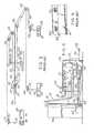
Figure 1 is a perspective view of a vehicle washing apparatus provided in accordance with the invention, a vehicle to be washed being illustrated in phantom lines;Figure 2 is a top view of a vehicle washing frame employed in patentUS-A-4,750,504 .Figure 3 is a diagrammatic view illustrating the operation of a piston and cylinder arrangement employed in the apparatus ofFigures 1 and2 ;Figure 4 is a side view of a control apparatus, partially broken away and partially in section, the control apparatus controlling the supply of water and a cleaning agent to the apparatus ofFigures 1 and2 ;Figure 5 is a fragmentary view of a portion of a frame employed inFigures 1 and2 to illustrate the mounting of nozzles, as in patentUS-A-4,750,504 , for the purpose of spraying vehicles to be washed;Figure 6 is a perspective view diagrammatically illustrating a system for operating overhead bars of the vehicle washing apparatus of the invention; andFigure 7 is a sectional view taken on lines 7-7 inFigure 1 .- Suspended from the ceiling is a
rectangular frame 34 includingend sections side sections Frame 34 rests upon thebight portions members - The apparatus includes a
carwashing frame 44. Both theframe 44 and theframe 34 are of corresponding rectangular configuration and both are maintained in at least substantially horizontal attitude. Theframe 44 includessides ends vehicle washing frame 44 is shown in raised position. Its lowered position is shown at 44' and an intermediate position is illustrated at 44". - In order to control the raising and lowering of
frame 44 with respect to vehicle V which is to be washed, there are connected to the frame 44 a plurality of lines orcables frame 44 and sufficiently flexible to be guided by a guiding system to be described hereinafter. Thelines rectangular frame 44 at spaced positions which are preferably located on theside sections frame 44 in stabilized position. - As will be described subsequently, the
frame 44 is provided at its interior with a plurality ofnozzles 64 which direct jets orplumes 66 of fluid and cleaning agent inwardly towards theinterior space 68 in which the vehicle V is located. These jets or plumes are directed against the vehicle and as theframe 44 is being raised and lowered, enable a cleaning of the vehicles by the force and action of the water and cleaning agent being directed thereagainst. - The
frame 44 is connected to a conduit or pair ofconduits 70 which are looped over thebight 32 as shown at 72. This conduit or pair of conduits is coupled to a control cabinet176, which is to be discussed in greater detail later. - Mounted from the
fixed frame 34 in a horizontal attitude are two transversely extendingoverhead bars overhead bars conduits 302 tocontrol cabinet 176. The overhead bars 300,301 are provided with downwardly facingnozzles 64 extending in spaced relation along the length of the overhead bars for discharging jets or plumes of a mixture of water and cleaning fluid downwardly onto the roof or top of vehicle V thereby to achieve cleaning thereof. Any excess of the mixture will flow along the sides of the vehicle and will mix with fluid ejected from the nozzles of theframe 44. - The
transverse bars respective plates 330 at their opposite ends which are guided for longitudinal movement inguides 331, in the form of slots, in theside sections fixed frame 34. Any other guide means will be suitable provided they act to guide the longitudinal movement of theplates 330 with respect to theside sections - The
plate 330 of thebars side sections drive system 350 to be described in greater detail later. - In
Figure 2 are illustrated acylinder 80, apiston 82 and apiston rod 84. These elements are all in horizontal attitude. Thepiston 82 is accommodated within thecylinder 80 and is displaced by compressed air supplied bylines 86 and 88 connected at opposite ends of thecylinder 80 by means offixtures 90 and 91. Compressed air is fed tolines 86 and 88 by an arrangement to be discussed hereinbelow. - Mounted in extension of the
cylinder 80 is a U-shaped channel 94 within which is accommodated ayoke 96. Theyoke 96 is connected to the free-end ofpiston rod 84. Wheels 98 and 100 are connected to opposite ends of theyoke 96 and are received in the U-shaped channel 94 to facilitate movement of the yoke therealong to a displaced position such as, for example, shown at 96'. - A plurality of lines are coupled to the
yoke 96. As will be shown hereinafter, these lines are all parts of a single main line. The lines have been referred to hereinabove aslines carwashing frame 44 whose raised or lowered position or positions are controlled by the playing out and retrieving of the various lines which in turn is controlled by the position of theyoke 96 under the control of the piston andcylinder arrangement - The lines are guided by a guiding system consisting of a plurality of pulleys or rollers preferably fabricated of Teflon or other suitable plastic adapted for constituting a relatively noise-free and effective guiding system. The system includes more particularly pulleys or
rollers carwashing frame 44. - It will be further seen in
Figure 2 that theframe 34 is provided withsupports side 42 and aninterior element 122 extending longitudinally along theframe 44.Supports cylinder 80 and firmly hold the same in position. Operation of compressed air in thecylinder 80 displacespiston 82, thereby controlling the playing out of the various lines and the retrieving of the same. The weight of theframe 44 is adequate to hold the various lines fully extended or taut so that no entanglement of these lines can occur. - Also appearing in
Figure 2 is the longitudinally disposedmember 128. Supported between this member and theside 40 offrame 34 is the sheet member 130. Similarly, asheet member 132 is supported betweenside 42 and a longitudinally disposedmember 122. It is in these sheet members that openings are provided for the lines passing around the various pulleys as next explained with reference toFigure 3 . - In
Figure 3 are illustrated the above-mentionedpulleys pulleys openings Fig. 2 ). - Also seen in
Figure 3 are the attachingmembers various lines carwashing frame 44. Figure 3 illustrates that, as aforesaid, thelines Figure 3 moreover illustrates that these lines can be part of a single main line, theline 54 being connected to line 56 by means ofbight 150 and theline 58 being connected to line 60 bybight 152. Thus, the lines are connected to theyoke 56 through which they extend in monolithic relationship with one another with thebights yoke 96, the movement of which is indicated by double-headedarrow 154, this being controlled by operation of the piston and cylinder arrangement through the intermediary ofpiston rod 84 as has been discussed hereinabove.- The cleaning system includes a tank 160 for storing and dispensing water and a
tank 162 for storing and dispensing a cleaning agent such as liquid soap or the like. Tank 160 is connected viaconduit 164 towater pump 166.Tank 162 is connected viaconduit 168 to a liquid soap pump 170. Avalve 172 with a control handle 174 is provided inconduit 164. - The bulk of the controls are contained in
control cabinet 176 from which extendlines 86 and 88, as aforesaid, to the cylinder 80 (seeFig. 2 ). Thesecompressed air lines 86 and 88 are attached to an air valve 177, in turn connected to aregulator 178, in turn coupled via aline 180 to a source of compressed air (not shown). Conduit 70 for supplying water and cleaning agent to theframe 44 are shown inFig. 4 as consisting ofrespective lines frame 44, whereat they are dispensed throughnozzles 64 in jets or plumes directed against the vehicle to be washed.- The apparatus further comprises a timer 190 housed within the control cabinet and connected via a
line 192 to thepump 166 to control operation of the same. Operation of thepump 166 simultaneously controls Operation of the soap pump 170. Power is supplied to the timer and the pumps by means ofelectrical lines plug 198 of conventional type. Figure 5 illustrates a section offrame 44 defining therein achannel 200 within which is accommodatednozzles 64. Thenozzles 64 are of such a length as to be accommodated within the depth of thechannel 200 to be protected thereby. Theframe 44 moreover defines ahousing 202 within which pass the lines coupling thelines nozzles 64 for the direction of water and cleaning agent against the vehicle V.- The relatively
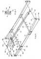
large horsepower pump 166 integrates with the soap pump 170 dispensing chemical cleaners automatically into the system. The frames which have been mentioned hereinabove are preferably formed of anodized aluminum material which is extra strong and will not rust. Thenozzles 64 mentioned hereinabove are brass nozzles of a design to provide increased water flow and stronger spray patterns then heretofore available. The Teflon rollers mentioned hereinabove are relatively noise-free and provide for lowering thecarwashing frame 44 quietly and smoothly. Figure 6 illustrates the details ofsystem 350 for moving theplates 330 at the ends of theoverhead bars system 350 is similar to that described for raising and loweringframe 44 in thatsystem 350 employs lines, pulleys and a piston-cylinder drive. Namely,system 350 includes aline 351 having oneend 352 fixed to the fixedframe 34 and anopposite end 353 fixed to aplate 330. Theline 351 extends from fixedend 352 around adrive pulley 354 with a horizontal axis, then around apulley 355 with a vertical axis, whereafter theline 351 extends around apulley 356 having a horizontal axis wherefrom the line extends downwardly around apulley 357 and then to itsend 353 secured to plate 330. Thesystem 350 further includes asecond line 360 having afixed end 361 from which theline 360 passes on asecond drive pulley 362 to travel in reverse to apulley 363 having a vertical axis of rotation. Theline 360 then passes on apulley 364 having a horizontal axis to apulley 365 having a horizontal axis perpendicular to the axis ofpulley 364 and wherefrom the line extends to afixed point 366 onplate 330 attached tooverhead bar 301.- The
system 350 further includes aline 370 having oneend 371 fixed to plate 330 of the otheroverhead bar 300. Theline 370 extends from fixedend 371 around apulley 372 having a horizontal axis to afixed point 373 onplate 330 connected tooverhead bar 301. - The
system 350 further includes aline 380 which has oneend 381 fixed to plate 330 onoverhead bar 300 and which passes around apulley 382 having a horizontal axis to apoint 383 onplate 330 ofoverhead bar 301. - The
system 350 also includes a piston-cylinder arrangement 390 similar to the piston-cylinder arrangement cylinder arrangement 390 is connected byflexible lines 391 toregulator 178 connected to the compressed air supply (not shown). The piston rod of the piston-cylinder arrangement is connected to agear device 392 of conventional design which converts linear movement of the piston rod into rotary movement of anoutput shaft 393. The drive pulleys 354 and 362 are fixed tooutput shaft 393 to undergo rotation when the piston rod is displaced. - The
pulleys frame 34 for travel longitudinally in opposite directions as indicated by the double headed arrow. - It is to be noted that
lines output shaft 393 theplates 330 will be respectively moved towards or away from one another. In particular, for a clockwise rotation of the drive pulleys,line 351 pullsplate 330 onbar 301 rearwards inFig. 6 whileline 360 is played out andline 370 is tensioned and pullsplate 330 onbar 300 forwardly inFig. 6 in synchronism with theplate 330 onbar 301 whileline 380 is played out. The platform P supporting the drive unit concurrently moves rearwards. For a counterclockwise rotation ofoutput shaft 393,line 360 is tensioned to pullplate 330 onbar 301 in a forwards direction whileline 380 pullsplate 330 onbar 300 rearwards towards theplate 330 onbar 301 in synchronism.Lines - The operation is as follows. When the piston rod is displaced so that the drive pulleys 354 and 362 rotate clockwise, forces are exerted on
plates 330 attached tooverhead bars plates 330 move towards one another. Asystem 400 of lines and pulleys corresponding tosystem 350 is provided for concurrently moving theplates 330 at the opposite ends of the overhead bars whereby the bars move in synchronism towards and away from one another while maintaining a parallel relation transversely of the vehicle. - The drive pulleys of
system 400 are mounted on platform P and are driven by the piston-cylinder arrangement 390 in concurrence with the drive pulleys 354, 362. - The
regulator 178 controls the supply of compressed air to the piston-cylinder arrangement of the overhead bars and to the piston-cylinder frame 44 so that the overhead bars are moved concurrently with the movement offrame 44. Thereby, the wash time of the vehicle is considerably shortened. A separate control means can be provided, if desired, to operate the movement of theframe 44 and theoverhead bars - In order to assure smooth travel of the
plates 330, the plates are slidably fitted at the top and bottom edges thereof inslots 410 provided in theside sections frame 34.Figure 7 is a section taken throughside section 42 and therein can be seenplate 330 whose top and bottom edges are slidably fitted inslots 410 in upper and lower flanges of theside section 42. In an alternate arrangement, theplates 330 are slidable at the backfaces of thesections overhead bars sections - As previously stated the drive pulleys 354 and 362 as well as the piston-
cylinder arrangement 390 are supported for tracking movement as a unit when the piston-cylinder arrangement is actuated, whereas the other pulleys, which change direction of the lines, rotate about stationary axes. In the corresponding arrangement in thesystem 400 the drive pulleys travel together with the drive pulleys ofsystem 350 while the line direction changing pulleys are stationary. - The supply of water and cleaning fluid to the overhead bars via
conduits 302 and 303 is controlled by valves (not shown) which supply the water and cleaning fluid fromtanks 160 and 162. These valves are located incontrol cabinet 176. - An automatic system may be provided in accordance with the invention so that as soon as they frame 44 reaches hub cap level with respect to the vehicle V, the chemical pump begins to operate to eject water from
frame 44 and theoverhead bars frame 44 rises and overhead bars traverse spraying water and preferably biodegradable chemical cleanser over the entire vehicle. - There will now be obvious to those skilled in the art, many modifications and variations of the apparatus set forth hereinabove. These modifications and variations will not depart from the scope of the invention as defined by the following claims.
Claims (6)
- A vehicle washing apparatus having fixed support means (34), a frame (44) adapted for encircling a vehicle, suspension means (54,56,58,60) for raising any lowering said frame with respect to said fixed support means and with respect to the vehicle encircled by said frame, and means for ejecting fluid (64) from the frame against the vehicle to clean the vehicle,characterized in that
transversely spaced fixed longitudinal members (331) are supported by said fixed support means,
a first overhead bar (300) and a second overhead bar (301), both having opposite ends and including support elements at said opposite ends mounted for displacement on and along said fixed longitudinal members, the two bars being moveable towards and away from each other;
a drive system (350) provided for producing said displacement of said overhead bars along said fixed longitudinal members, and
means provided for ejecting fluid downwardly (364) from said overhead bars for cleaning the vehicle from above. - The apparatus according to claim 1,characterized in that said bars (300, 301) extend transversely of the fixed longitudinal members and are displaceable longitudinally of the vehicle in a horizontal plane thereabove.
- The apparatus according to claim 1,characterized in that said drive system (350) for producing said displacement of said overhead bars (300,301) comprises lines (351,360) connected to said support elements to move said overhead bars conjointly.
- The apparatus according to claim 3, comprising pulleys (354,362) supporting said lines (351,360) and a piston-cylinder (390) connected to said pulleys to move said lines and thereby move said overhead bars.
- The apparatus according to claim 4,characterized in that said support elements each comprise a plate (330) which is slidable on a respective one of said fixed longitudinal members (331) and said lines (351,360) are connected to opposite sides of said plates.
- The apparatus according to claim 1,characterized in that said overhead bars (300,301) are hollow and have discharge nozzles (364) facing downwards toward said vehicle, fluid lines (302) being connected to said overhead bars so that said fluid is ejected from the nozzles in the bars.
Applications Claiming Priority (3)
| Application Number | Priority Date | Filing Date | Title |
|---|---|---|---|
| US10/121,245US6810889B2 (en) | 2001-04-16 | 2002-04-12 | Vehicle washing apparatus |
| US121245 | 2002-04-12 | ||
| PCT/US2003/010760WO2003086669A1 (en) | 2002-04-12 | 2003-04-09 | Vehicle washing apparatus |
Publications (3)
| Publication Number | Publication Date |
|---|---|
| EP1562713A1 EP1562713A1 (en) | 2005-08-17 |
| EP1562713A4 EP1562713A4 (en) | 2007-09-26 |
| EP1562713B1true EP1562713B1 (en) | 2010-11-17 |
Family
ID=29248295
Family Applications (1)
| Application Number | Title | Priority Date | Filing Date |
|---|---|---|---|
| EP03718266AExpired - LifetimeEP1562713B1 (en) | 2002-04-12 | 2003-04-09 | Vehicle washing apparatus |
Country Status (6)
| Country | Link |
|---|---|
| US (1) | US6810889B2 (en) |
| EP (1) | EP1562713B1 (en) |
| AT (1) | ATE488307T1 (en) |
| AU (1) | AU2003221688A1 (en) |
| DE (1) | DE60335021D1 (en) |
| WO (1) | WO2003086669A1 (en) |
Families Citing this family (5)
| Publication number | Priority date | Publication date | Assignee | Title |
|---|---|---|---|---|
| US20040035447A1 (en)* | 2002-03-08 | 2004-02-26 | Schleeter Keith M. | Method and apparatus for manipulating a spray bar |
| FR2851977B1 (en)* | 2003-03-07 | 2005-05-20 | Rondeau Freres | METHOD AND INSTALLATION FOR AT LEAST PARTIAL CLEANING OF A LOAD HANDLING MACHINE |
| DE102017213295B4 (en)* | 2016-08-02 | 2025-05-28 | Xerox Corporation | IMPROVED SYSTEM FOR CLEANING COMPONENTS USED TO CLEAN INKJET PRINTHEADS IN INKJET PRINTERS |
| US10046566B2 (en)* | 2016-08-02 | 2018-08-14 | Xerox Corporation | System for cleaning components used to clean inkjet printheads in inkjet printers |
| US11639156B2 (en)* | 2021-03-17 | 2023-05-02 | Jose Garcia | Portable vehicle washing assembly |
Family Cites Families (10)
| Publication number | Priority date | Publication date | Assignee | Title |
|---|---|---|---|---|
| US2689577A (en)* | 1951-06-12 | 1954-09-21 | Choldun Mfg Corp | Apparatus for washing vehicles |
| US3324868A (en)* | 1965-06-10 | 1967-06-13 | Choldun Mfg Corp | Car wash installation |
| US3545459A (en)* | 1966-01-27 | 1970-12-08 | Jet Cit Thru Inc | Vehicle washing apparatus |
| US3650281A (en)* | 1968-12-24 | 1972-03-21 | Malsbary Mfg Co | Automatic carwash apparatus |
| US3726293A (en)* | 1971-11-11 | 1973-04-10 | Detergent Eng Corp | Vehicle cleaning system |
| US4303087A (en)* | 1979-10-19 | 1981-12-01 | Michael Flaxman | Automobile washing and drying installation |
| US4750504A (en) | 1986-09-24 | 1988-06-14 | Hercules Car Wash International | Vehicle washing apparatus |
| US4809720A (en)* | 1987-12-07 | 1989-03-07 | Heraty Patrick T | Brushless vehicle washing apparatus |
| US6237614B1 (en)* | 1999-04-05 | 2001-05-29 | Dale Retter | Retractable vehicle wash system |
| US6372053B1 (en)* | 1999-10-01 | 2002-04-16 | Michael J. Belanger | Rollover pressure car wash apparatus and methods of operating same |
- 2002
- 2002-04-12USUS10/121,245patent/US6810889B2/ennot_activeExpired - Lifetime
- 2003
- 2003-04-09WOPCT/US2003/010760patent/WO2003086669A1/ennot_activeApplication Discontinuation
- 2003-04-09AUAU2003221688Apatent/AU2003221688A1/ennot_activeAbandoned
- 2003-04-09DEDE60335021Tpatent/DE60335021D1/ennot_activeExpired - Lifetime
- 2003-04-09EPEP03718266Apatent/EP1562713B1/ennot_activeExpired - Lifetime
- 2003-04-09ATAT03718266Tpatent/ATE488307T1/ennot_activeIP Right Cessation
Also Published As
| Publication number | Publication date |
|---|---|
| ATE488307T1 (en) | 2010-12-15 |
| US6810889B2 (en) | 2004-11-02 |
| EP1562713A4 (en) | 2007-09-26 |
| DE60335021D1 (en) | 2010-12-30 |
| US20020148490A1 (en) | 2002-10-17 |
| WO2003086669A1 (en) | 2003-10-23 |
| AU2003221688A1 (en) | 2003-10-27 |
| EP1562713A1 (en) | 2005-08-17 |
Similar Documents
| Publication | Publication Date | Title |
|---|---|---|
| US5178252A (en) | Telescopic chute for a mixer truck | |
| WO1991017032A1 (en) | Telescoping chute for a cement delivery truck | |
| EP1562713B1 (en) | Vehicle washing apparatus | |
| CN111927053A (en) | A high-efficient device of wipeing wall for interior decoration | |
| US20030145410A1 (en) | Automated washing apparatus for windowpanes | |
| US4750504A (en) | Vehicle washing apparatus | |
| US5452859A (en) | Vehicle washing apparatus | |
| EP1621428B1 (en) | Car wash installation and corresponding process | |
| CN218871756U (en) | Spraying device for wet desulphurization | |
| JP2002524175A (en) | Cleaning devices for sliding windows or door wings | |
| CN217601608U (en) | Spray gun assembly and closestool | |
| CN214219307U (en) | Road pavement maintenance device | |
| AU2003286058B2 (en) | Pipe scarifier | |
| CN2413807Y (en) | Outer curtain wall cleaner for high-rise building | |
| JP3426507B2 (en) | Mobile liquid supply device | |
| CN110076113A (en) | A kind of municipal works cable cleaning machine | |
| CN114011820B (en) | Cleaning device for chemical teaching instrument and using method thereof | |
| CN215758766U (en) | Can wash for watering lorry at road surface dead angle spout device in | |
| CN217473917U (en) | Reciprocating type powder spraying equipment | |
| CN86105240A (en) | tank flushing system | |
| KR100439605B1 (en) | Auto cleaner for domes of tunnels | |
| CN219214959U (en) | Main body frame of outdoor automatic car washer | |
| CN221580902U (en) | Spraying device for pier maintenance | |
| SU1419663A1 (en) | Arrangement for washing gable roof | |
| CN214976104U (en) | Adjustable solar panel belt cleaning device |
Legal Events
| Date | Code | Title | Description |
|---|---|---|---|
| PUAI | Public reference made under article 153(3) epc to a published international application that has entered the european phase | Free format text:ORIGINAL CODE: 0009012 | |
| 17P | Request for examination filed | Effective date:20050221 | |
| AK | Designated contracting states | Kind code of ref document:A1 Designated state(s):AT BE BG CH CY CZ DE DK EE ES FI FR GB GR HU IE IT LI LU MC NL PT RO SE SI SK TR | |
| A4 | Supplementary search report drawn up and despatched | Effective date:20070823 | |
| 17Q | First examination report despatched | Effective date:20080707 | |
| GRAP | Despatch of communication of intention to grant a patent | Free format text:ORIGINAL CODE: EPIDOSNIGR1 | |
| GRAS | Grant fee paid | Free format text:ORIGINAL CODE: EPIDOSNIGR3 | |
| GRAA | (expected) grant | Free format text:ORIGINAL CODE: 0009210 | |
| AK | Designated contracting states | Kind code of ref document:B1 Designated state(s):AT BE BG CH CY CZ DE DK EE ES FI FR GB GR HU IE IT LI LU MC NL PT RO SE SI SK TR | |
| REG | Reference to a national code | Ref country code:GB Ref legal event code:FG4D | |
| REG | Reference to a national code | Ref country code:CH Ref legal event code:EP | |
| REG | Reference to a national code | Ref country code:IE Ref legal event code:FG4D | |
| REF | Corresponds to: | Ref document number:60335021 Country of ref document:DE Date of ref document:20101230 Kind code of ref document:P | |
| REG | Reference to a national code | Ref country code:NL Ref legal event code:VDEP Effective date:20101117 | |
| PG25 | Lapsed in a contracting state [announced via postgrant information from national office to epo] | Ref country code:NL Free format text:LAPSE BECAUSE OF FAILURE TO SUBMIT A TRANSLATION OF THE DESCRIPTION OR TO PAY THE FEE WITHIN THE PRESCRIBED TIME-LIMIT Effective date:20101117 Ref country code:PT Free format text:LAPSE BECAUSE OF FAILURE TO SUBMIT A TRANSLATION OF THE DESCRIPTION OR TO PAY THE FEE WITHIN THE PRESCRIBED TIME-LIMIT Effective date:20110317 Ref country code:SI Free format text:LAPSE BECAUSE OF FAILURE TO SUBMIT A TRANSLATION OF THE DESCRIPTION OR TO PAY THE FEE WITHIN THE PRESCRIBED TIME-LIMIT Effective date:20101117 Ref country code:CY Free format text:LAPSE BECAUSE OF FAILURE TO SUBMIT A TRANSLATION OF THE DESCRIPTION OR TO PAY THE FEE WITHIN THE PRESCRIBED TIME-LIMIT Effective date:20101117 Ref country code:BG Free format text:LAPSE BECAUSE OF FAILURE TO SUBMIT A TRANSLATION OF THE DESCRIPTION OR TO PAY THE FEE WITHIN THE PRESCRIBED TIME-LIMIT Effective date:20110217 Ref country code:SE Free format text:LAPSE BECAUSE OF FAILURE TO SUBMIT A TRANSLATION OF THE DESCRIPTION OR TO PAY THE FEE WITHIN THE PRESCRIBED TIME-LIMIT Effective date:20101117 Ref country code:AT Free format text:LAPSE BECAUSE OF FAILURE TO SUBMIT A TRANSLATION OF THE DESCRIPTION OR TO PAY THE FEE WITHIN THE PRESCRIBED TIME-LIMIT Effective date:20101117 Ref country code:FI Free format text:LAPSE BECAUSE OF FAILURE TO SUBMIT A TRANSLATION OF THE DESCRIPTION OR TO PAY THE FEE WITHIN THE PRESCRIBED TIME-LIMIT Effective date:20101117 | |
| PG25 | Lapsed in a contracting state [announced via postgrant information from national office to epo] | Ref country code:GR Free format text:LAPSE BECAUSE OF FAILURE TO SUBMIT A TRANSLATION OF THE DESCRIPTION OR TO PAY THE FEE WITHIN THE PRESCRIBED TIME-LIMIT Effective date:20110218 | |
| PG25 | Lapsed in a contracting state [announced via postgrant information from national office to epo] | Ref country code:BE Free format text:LAPSE BECAUSE OF FAILURE TO SUBMIT A TRANSLATION OF THE DESCRIPTION OR TO PAY THE FEE WITHIN THE PRESCRIBED TIME-LIMIT Effective date:20101117 Ref country code:CZ Free format text:LAPSE BECAUSE OF FAILURE TO SUBMIT A TRANSLATION OF THE DESCRIPTION OR TO PAY THE FEE WITHIN THE PRESCRIBED TIME-LIMIT Effective date:20101117 Ref country code:ES Free format text:LAPSE BECAUSE OF FAILURE TO SUBMIT A TRANSLATION OF THE DESCRIPTION OR TO PAY THE FEE WITHIN THE PRESCRIBED TIME-LIMIT Effective date:20110228 Ref country code:EE Free format text:LAPSE BECAUSE OF FAILURE TO SUBMIT A TRANSLATION OF THE DESCRIPTION OR TO PAY THE FEE WITHIN THE PRESCRIBED TIME-LIMIT Effective date:20101117 | |
| PG25 | Lapsed in a contracting state [announced via postgrant information from national office to epo] | Ref country code:SK Free format text:LAPSE BECAUSE OF FAILURE TO SUBMIT A TRANSLATION OF THE DESCRIPTION OR TO PAY THE FEE WITHIN THE PRESCRIBED TIME-LIMIT Effective date:20101117 Ref country code:RO Free format text:LAPSE BECAUSE OF FAILURE TO SUBMIT A TRANSLATION OF THE DESCRIPTION OR TO PAY THE FEE WITHIN THE PRESCRIBED TIME-LIMIT Effective date:20101117 Ref country code:DK Free format text:LAPSE BECAUSE OF FAILURE TO SUBMIT A TRANSLATION OF THE DESCRIPTION OR TO PAY THE FEE WITHIN THE PRESCRIBED TIME-LIMIT Effective date:20101117 | |
| PLBE | No opposition filed within time limit | Free format text:ORIGINAL CODE: 0009261 | |
| STAA | Information on the status of an ep patent application or granted ep patent | Free format text:STATUS: NO OPPOSITION FILED WITHIN TIME LIMIT | |
| PGFP | Annual fee paid to national office [announced via postgrant information from national office to epo] | Ref country code:IT Payment date:20110330 Year of fee payment:9 | |
| 26N | No opposition filed | Effective date:20110818 | |
| PG25 | Lapsed in a contracting state [announced via postgrant information from national office to epo] | Ref country code:MC Free format text:LAPSE BECAUSE OF NON-PAYMENT OF DUE FEES Effective date:20110430 | |
| REG | Reference to a national code | Ref country code:CH Ref legal event code:PL | |
| REG | Reference to a national code | Ref country code:DE Ref legal event code:R097 Ref document number:60335021 Country of ref document:DE Effective date:20110818 | |
| PG25 | Lapsed in a contracting state [announced via postgrant information from national office to epo] | Ref country code:CH Free format text:LAPSE BECAUSE OF NON-PAYMENT OF DUE FEES Effective date:20110430 Ref country code:LI Free format text:LAPSE BECAUSE OF NON-PAYMENT OF DUE FEES Effective date:20110430 | |
| REG | Reference to a national code | Ref country code:IE Ref legal event code:MM4A | |
| PG25 | Lapsed in a contracting state [announced via postgrant information from national office to epo] | Ref country code:IE Free format text:LAPSE BECAUSE OF NON-PAYMENT OF DUE FEES Effective date:20110409 | |
| GBPC | Gb: european patent ceased through non-payment of renewal fee | Effective date:20120409 | |
| PG25 | Lapsed in a contracting state [announced via postgrant information from national office to epo] | Ref country code:IT Free format text:LAPSE BECAUSE OF NON-PAYMENT OF DUE FEES Effective date:20120409 | |
| PG25 | Lapsed in a contracting state [announced via postgrant information from national office to epo] | Ref country code:LU Free format text:LAPSE BECAUSE OF NON-PAYMENT OF DUE FEES Effective date:20110409 | |
| PG25 | Lapsed in a contracting state [announced via postgrant information from national office to epo] | Ref country code:TR Free format text:LAPSE BECAUSE OF FAILURE TO SUBMIT A TRANSLATION OF THE DESCRIPTION OR TO PAY THE FEE WITHIN THE PRESCRIBED TIME-LIMIT Effective date:20101117 | |
| PG25 | Lapsed in a contracting state [announced via postgrant information from national office to epo] | Ref country code:HU Free format text:LAPSE BECAUSE OF FAILURE TO SUBMIT A TRANSLATION OF THE DESCRIPTION OR TO PAY THE FEE WITHIN THE PRESCRIBED TIME-LIMIT Effective date:20101117 | |
| REG | Reference to a national code | Ref country code:GB Ref legal event code:S28 Free format text:APPLICATION FILED | |
| REG | Reference to a national code | Ref country code:GB Ref legal event code:S28 Free format text:RESTORATION ALLOWED Effective date:20140409 | |
| REG | Reference to a national code | Ref country code:FR Ref legal event code:PLFP Year of fee payment:14 | |
| PG25 | Lapsed in a contracting state [announced via postgrant information from national office to epo] | Ref country code:GB Free format text:THE PATENT HAS BEEN ANNULLED BY A DECISION OF A NATIONAL AUTHORITY Effective date:20120409 | |
| REG | Reference to a national code | Ref country code:FR Ref legal event code:PLFP Year of fee payment:15 | |
| REG | Reference to a national code | Ref country code:FR Ref legal event code:PLFP Year of fee payment:16 | |
| PGFP | Annual fee paid to national office [announced via postgrant information from national office to epo] | Ref country code:DE Payment date:20190326 Year of fee payment:17 | |
| REG | Reference to a national code | Ref country code:DE Ref legal event code:R119 Ref document number:60335021 Country of ref document:DE | |
| PG25 | Lapsed in a contracting state [announced via postgrant information from national office to epo] | Ref country code:DE Free format text:LAPSE BECAUSE OF NON-PAYMENT OF DUE FEES Effective date:20201103 | |
| PGFP | Annual fee paid to national office [announced via postgrant information from national office to epo] | Ref country code:FR Payment date:20210309 Year of fee payment:19 | |
| PGFP | Annual fee paid to national office [announced via postgrant information from national office to epo] | Ref country code:GB Payment date:20210317 Year of fee payment:19 | |
| GBPC | Gb: european patent ceased through non-payment of renewal fee | Effective date:20220409 | |
| PG25 | Lapsed in a contracting state [announced via postgrant information from national office to epo] | Ref country code:GB Free format text:THE PATENT HAS BEEN ANNULLED BY A DECISION OF A NATIONAL AUTHORITY Effective date:20220409 Ref country code:FR Free format text:LAPSE BECAUSE OF NON-PAYMENT OF DUE FEES Effective date:20220430 |