EP1561610B1 - Trailer hitch mechanism - Google Patents
Trailer hitch mechanismDownload PDFInfo
- Publication number
- EP1561610B1 EP1561610B1EP05002471AEP05002471AEP1561610B1EP 1561610 B1EP1561610 B1EP 1561610B1EP 05002471 AEP05002471 AEP 05002471AEP 05002471 AEP05002471 AEP 05002471AEP 1561610 B1EP1561610 B1EP 1561610B1
- Authority
- EP
- European Patent Office
- Prior art keywords
- fitting piece
- trailer hitch
- ball
- bearing head
- pivot axis
- Prior art date
- Legal status (The legal status is an assumption and is not a legal conclusion. Google has not performed a legal analysis and makes no representation as to the accuracy of the status listed.)
- Expired - Lifetime
Links
- 230000008878couplingEffects0.000claimsdescription12
- 238000010168coupling processMethods0.000claimsdescription12
- 238000005859coupling reactionMethods0.000claimsdescription12
- 241001125877Gobio gobioSpecies0.000claims1
- 210000003128headAnatomy0.000description15
- 238000006073displacement reactionMethods0.000description3
- 230000000295complement effectEffects0.000description1
- 239000002131composite materialSubstances0.000description1
- 238000010924continuous productionMethods0.000description1
Images


Classifications
- B—PERFORMING OPERATIONS; TRANSPORTING
- B60—VEHICLES IN GENERAL
- B60D—VEHICLE CONNECTIONS
- B60D1/00—Traction couplings; Hitches; Draw-gear; Towing devices
- B60D1/48—Traction couplings; Hitches; Draw-gear; Towing devices characterised by the mounting
- B60D1/54—Traction couplings; Hitches; Draw-gear; Towing devices characterised by the mounting collapsible or retractable when not in use, e.g. hide-away hitches
- B—PERFORMING OPERATIONS; TRANSPORTING
- B60—VEHICLES IN GENERAL
- B60D—VEHICLE CONNECTIONS
- B60D1/00—Traction couplings; Hitches; Draw-gear; Towing devices
- B60D1/24—Traction couplings; Hitches; Draw-gear; Towing devices characterised by arrangements for particular functions
- B60D1/246—Traction couplings; Hitches; Draw-gear; Towing devices characterised by arrangements for particular functions for actuating the hitch by powered means
Definitions
- the inventionrelates to a trailer hitch for motor vehicles with the features specified in the preamble of the independent claim.
- Thisis done in two movement sections with controlled by the geometric design of a guide slot of a backdrop-like guide device movements.
- the previously pivoted about a horizontal pivot axis ball rodcan be rotated.
- no fittingis pressed with positive connection in a recording, but there are stop elements and members provided, against which the ball bar is held under contact pressure.
- the ball baritself is part of a spindle of a spindle-nut drive and axially adjustable. It has a screwed adjusting spindle, which is rotated via a spur and planetary gear by an electric motor.
- the ball rodis arranged in a guide sleeve, which is formed with a positive guide and causes after a guided axial displacement, the ball rod is then rotated in its operating position upwardly pointing ball.
- the inventionhas for its object to provide a trailer hitch of the type mentioned above, a reliable, simple pivoting, by hand or preferably motor, the ball bar allows to pivot with the least possible movement space in the working position or vice versa.
- An embodiment of the inventionprovides that the pivot axes are aligned obliquely. By simply varying the angle of inclination of the hinge axes, the movement can be easily adapted to the respective premises at the rear of the vehicle.
- a common for the two pivot axes hinge eye support plateis arranged on a movably guided Bodengleitplatte the coupling housing.
- the pivoting movementsonce to the substantially vertical pivot axis for engagement or disengagement of the fitting piece and then the further pivoting of the bearing head with the ball rod and only then to the substantially horizontal pivot axis, wherein the hinge eye support plate to the substantially horizontal pivot axis is lifted obliquely upwards, can be forced in this way successively, however, perform in a continuous process.
- the movably guided bottom sliding platecreates with the axial displacement the space for the input or disengagement of the locking of the bearing head.
- a tension springacts on the floor sliding plate, this supports the defined movement sequences, since the hinge eye support plate then occupies a specifically determined end position in any case.
- the bearing headis sandwiched and has a coupling piece of the drive device between an upper and a lower fitting piece. While the lower fitting piece may be formed integrally with the ball rod from the outset, the upper fitting piece is first placed after the coupling piece having an eye-like mounting opening has been fitted.
- the hinge bearingby a in hinge eyes of the fittings and the enclosed by these Hinge eye of the support plate inserted pivot axis, namely a bolt, then produces the uniform composite of these parts.
- a preferred embodiment of the inventionprovides that the fitting piece and the fitting piece are formed with a ball lock.
- Thisconsists of either in the fitting piece or in the fitting piece receiving balls which engage in locking the working position of the ball bar in spherical caps of the respective complementary component and thus set the ball bar rotation.
- a ball lockcan be solved much easier than, for example, a wedge or tooth engagement in the rotational end position of the bearing head or the ball rod.
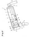
- FIGS. 1 to 10 illustrated trailer hitch 1 for motor vehicleshas a coupling housing 2 with a pivotally mounted therein, cranked, at its free end a coupling ball 3 supporting ball rod 4.
- a drive device 5is provided with a linear actuator, which has a threaded sleeve 6 and a standing with this engaging threaded spindle 7, which is driven by an electric drive motor 8.
- the ball rod 4is provided with a bearing head 9 which is formed here simultaneously with a fitting piece 10a (cf. FIG. 2 ), arranged in the clutch housing 2.
- a fitting piece 10a(cf. FIG. 2 ), arranged in the clutch housing 2.
- On a stud-like bearing head endare a coupling piece 11, via which the threaded sleeve 6 of the drive means 5 with the bearing head 9 and the ball rod 4 is connected, and an upper fitting piece 10 b attached.
- the fitting pieces 10a, 10bare provided with hinge eyes 12, which form a vertical pivot axis 15 with a hinge eye 13 of a support plate 14 by an inserted pin.
- hinge eye 16is attached to the support plate 14 below, which arranged with a movably guided bottom sliding plate 17 of the coupling housing 2 arranged hinge eyes 18 and a through the hinge eyes 16,17 bolts a second, here horizontal pivot axis 19 for the bearing head 9 and the ball rod 4 forms.
- the bearing head 9 adjacent end wall of the coupling housing 2is formed as a fitting receptacle 20 for the fitting pieces 10 a, 10 b, wherein a ball lock, consisting of arranged in the fitting piece receptacle 20 balls 21 (see. FIG. 7 ) and this in the fitting pieces 10 a, 10 b associated spherical caps 22 (see. FIG. 4 ) exists in the in FIGS. 1 and 2 shown working position of the ball bar 4 by the positive engagement this rotational end position of the ball bar 4 secures.
- a ball lockconsisting of arranged in the fitting piece receptacle 20 balls 21 (see. FIG. 7 ) and this in the fitting pieces 10 a, 10 b associated spherical caps 22 (see. FIG. 4 ) exists in the in FIGS. 1 and 2 shown working position of the ball bar 4 by the positive engagement this rotational end position of the ball bar 4 secures.
- the drive means 5For pivoting the ball rod 4 in its rest position, the drive means 5 is actuated and first the locking of the balls 21 in the spherical caps 22 is released (see Figures 3 and 4 ).
- the bottom sliding plate 17defines a linear adjustment path, and also the bearing head 9 with the fitting pieces 10a, 10b, due to the connection of the hinge eye support plate 14 via the hinge bearings 12,13 or 16,18 with the bearing head 9 on the one hand and the floor sliding plate on the other hand 17th
- FIG. 1schematically drawn tension spring 23.
- the bearing head 9pivots with its fitting pieces 10 a, 10 b about the pivot axis 15 of the hinge bearing 12,13; the drive device 5 or its threaded sleeve 6 and threaded spindle 7 are displaced in this case together with the coupling piece 11 and consequently the ball rod 4 slightly out of its central position to the rear (see. FIG. 5 ).
- the bearing head 9 with the ball rod 4is increasingly pivoted about the pivot axis 15 in the vehicle longitudinal direction end position until the fitting pieces 10 a, 10 b create the support plate 14, as the FIGS. 7 and 8th can be seen.
- the drive device 5causes a pivoting of the hinge-eye support plate 14 and thus of the bearing head 9 including ball bar 4 about the pivot axis 19 of the hinge bearing 16,18 of the bottom plate 17, whereby the laterally pivoted ball bar 4 in their in the Figures 9 and 10 shown raised end position or rest position reaches.
Landscapes
- Engineering & Computer Science (AREA)
- Transportation (AREA)
- Mechanical Engineering (AREA)
- Pivots And Pivotal Connections (AREA)
- Motor Or Generator Frames (AREA)
- Arrangement And Driving Of Transmission Devices (AREA)
- Glass Compositions (AREA)
- Insulation, Fastening Of Motor, Generator Windings (AREA)
Abstract
Description
Translated fromGermanDie Erfindung betrifft eine Anhängerkupplung für Kraftfahrzeuge mit den im Oberbegriff des unabhängigen Anspruchs angegebenen Merkmalen. Eine solche Anhängekupplung mit dort motorischem Antrieb zum Verschwenken der Kugelstange von einer Arbeitsstellung in eine Ruhestellung und umgekehrt ist durch die
Bei einer durch die
Aus der
Der Erfindung liegt die Aufgabe zugrunde, eine Anhängerkupplung der eingangs genannten Art zu schaffen, die ein betriebssicheres, einfaches Verschwenken, von Hand oder vorzugsweise motorisch, der Kugelstange ermöglicht, um diese mit geringstmöglichem Bewegungsraum in die Arbeitsstellung oder umgekehrt verschwenken zu können.The invention has for its object to provide a trailer hitch of the type mentioned above, a reliable, simple pivoting, by hand or preferably motor, the ball bar allows to pivot with the least possible movement space in the working position or vice versa.
Diese Aufgabe wird bei einer gattungsgemäßen Anhängerkupplung erfindungsgemäß dadurch gelöst, dass sich einem linearen axialen Verstellweg zum Ein- oder Ausrücken des Passstückes ein mit der Kugelstange gemeinsames Verschwenken um die vertikale und um die horizontale Schwenkachse anschließt. Es läßt sich hiermit eine exakte, klar definierte Zwangsführung des Bewegungsablaufs der Kugelstange erreichen. Das kann weiter begünstigt werden, wenn die Schwenkachsen vorzugsweise als Scharnierlagerungen ausgebildet sind, was am Ort des Geschehen festgelegte Drehpunkte ermöglicht.This object is achieved in a generic trailer hitch according to the invention that adjoins a linear axial displacement for engagement or disengagement of the fitting piece with the ball rod joint pivoting about the vertical and about the horizontal pivot axis. It can hereby achieve an exact, well-defined forced operation of the movement of the ball bar. This can further be favored if the pivot axes are preferably designed as hinge bearings, which allows fixed at the location of events pivot points.
Eine Ausgestaltung der Erfindung sieht vor, dass die Schwenkachsen schräg verlaufend ausgerichtet sind. Durch einfaches Variieren des Schrägwinkels der Scharnierachsen lässt sich der Bewegungsablauf ohne weiteres an die jeweiligen Räumlichkeiten am Fahrzeugheck anpassen.An embodiment of the invention provides that the pivot axes are aligned obliquely. By simply varying the angle of inclination of the hinge axes, the movement can be easily adapted to the respective premises at the rear of the vehicle.
Nach einem Vorschlag der Erfindung ist eine für die beiden Schwenkachsen gemeinsame Scharnieraugen-Trägerplatte auf einer beweglich geführten Bodengleitplatte des Kupplungsgehäuses angeordnet. Die Schwenkbewegungen, und zwar einmal um die im wesentlichen vertikale Schwenkachse zum Ein- oder Ausrücken des Passstückes sowie danach das weitere Verschwenken des Lagerkopfes mit der Kugelstange und erst dann um die im wesentlichen horizontale Schwenkachse, wobei die Scharnieraugen-Trägerplatte um die im wesentlichen horizontale Schwenkachse schräg nach oben angehoben wird, lassen sich auf diese Weise zwangsweise sukzessive, gleichwohl in einem kontinuierlichen Ablauf durchführen. Die beweglich geführte Bodengleitplatte schafft mit der axialen Verlagerung den Freiraum für die Ein- oder Ausrückbewegung der Verriegelung des Lagerkopfes.According to one proposal of the invention, a common for the two pivot axes hinge eye support plate is arranged on a movably guided Bodengleitplatte the coupling housing. The pivoting movements, once to the substantially vertical pivot axis for engagement or disengagement of the fitting piece and then the further pivoting of the bearing head with the ball rod and only then to the substantially horizontal pivot axis, wherein the hinge eye support plate to the substantially horizontal pivot axis is lifted obliquely upwards, can be forced in this way successively, however, perform in a continuous process. The movably guided bottom sliding plate creates with the axial displacement the space for the input or disengagement of the locking of the bearing head.
Wenn vorteilhaft an die Bodengleitplatte eine Zugfeder angreift, unterstützt das die definierten Bewegungsabläufe, da die Scharnieraugen-Trägerplatte dann auf jeden Fall eine gezielt bestimmte Endposition einnimmt.If advantageously a tension spring acts on the floor sliding plate, this supports the defined movement sequences, since the hinge eye support plate then occupies a specifically determined end position in any case.
Es wird erfindungsgemäß vorgeschlagen, dass der Lagerkopf sandwichartig aufgebaut ist und zwischen einem oberen und einem unteren Passstück ein Ankopplungsstück der Antriebseinrichtung aufweist. Während das untere Passstück von vornherein einstückig mit der Kugelstange ausgebildet sein kann, wird das obere Passstück erst aufgesetzt, nachdem das eine augenartige Montageöffnung aufweisende Ankopplungsstück aufgesteckt worden ist. Die Scharnierlagerung durch eine in Scharnieraugen der Passstücke und das von diesen eingeschlossene Scharnierauge der Trägerplatte gesteckte Schwenkachse, nämlich ein Bolzen, stellt dann den einheitlichen Verbund dieser Teile her.It is proposed according to the invention that the bearing head is sandwiched and has a coupling piece of the drive device between an upper and a lower fitting piece. While the lower fitting piece may be formed integrally with the ball rod from the outset, the upper fitting piece is first placed after the coupling piece having an eye-like mounting opening has been fitted. The hinge bearing by a in hinge eyes of the fittings and the enclosed by these Hinge eye of the support plate inserted pivot axis, namely a bolt, then produces the uniform composite of these parts.
Eine bevorzugte Ausführung der Erfindung sieht vor, dass die Passstückaufnahme und das Passstück mit einer Kugelverriegelung ausgebildet sind. Diese besteht aus entweder in dem Passstück oder in der Passstückaufnahme angeordneten Kugeln, die zur Verriegelung der Arbeitsstellung der Kugelstange in Kugelkalotten des jeweiligen komplementären Bauteiles eingreifen und damit die Kugelstange drehfest festlegen. Eine solche Kugelverriegelung lässt sich sehr viel leichter lösen als beispw. ein Keil oder Verzahnungseingriff in der Drehendstellung des Lagerkopfes bzw. der Kugelstange.A preferred embodiment of the invention provides that the fitting piece and the fitting piece are formed with a ball lock. This consists of either in the fitting piece or in the fitting piece receiving balls which engage in locking the working position of the ball bar in spherical caps of the respective complementary component and thus set the ball bar rotation. Such a ball lock can be solved much easier than, for example, a wedge or tooth engagement in the rotational end position of the bearing head or the ball rod.
Weitere Merkmale und Einzelheiten der Erfindung ergeben sich aus den Ansprüchen und der nachfolgenden Beschreibung eines in den Zeichnungen dargestellten Ausführungsbeispiels der Erfindung. Es zeigen:
Figuren - in perspektivischer Draufsicht (
Figur 1 ) bzw. Vorderansicht (Figur 2 ) eine Anhängerkupplung mit ihrer in der Arbeitsstellung drehfest verriegelten Kugelstange; Figuren - Ansichten der Anhängerkupplung wie zuvor mit demgegenüber zum Schwenken ausgerückter bzw. entriegelter Kugelstange;
Figuren - Ansichten der Anhängerkupplung wie zuvor in einer FolgeSchwenkposition der Kugelstange;
Figuren - Ansichten der Anhängerkupplung wie zuvor mit in ihre Endlage quer zur Fahrzeuglängsrichtung verschwenkter Kugelstange; und
Figuren 9,10- Ansichten der Anhängerkupplung wie zuvor mit aus der Endstellung nach den
Figuren 78 in eine hochstehende, unsichtbare Position ihrer Kupplungskugel in die Ruhestellung verschwenkter Kugelstange.
- Figures 1,2
- in perspective plan view (
FIG. 1 ) or front view (FIG. 2 ) a trailer hitch with its locked in the working position ball rod; - Figures 3,4
- Views of the trailer hitch as before with the opposite swinging or unlocked ball bar;
- Figures 5,6
- Views of the trailer hitch as before in a subsequent pivoting position of the ball bar;
- FIGS. 7,8
- Views of the trailer hitch as before with in its end position transverse to the vehicle longitudinal direction pivoted ball bar; and
- FIGS. 9, 10
- Views of the trailer hitch as before with from the end position to the
FIGS. 7 and8th in a high, invisible position of their coupling ball in the rest position pivoted ball bar.
Eine in den
Die Kugelstange 4 ist mit einem Lagerkopf 9, der hier gleichzeitig mit einem als Passstück 10a ausgebildet ist (vgl.
Die dem Lagerkopf 9 benachbarte Endwand des Kupplungsgehäuses 2 ist als Passstückaufnahme 20 für die Passstücke 10a, 10b ausgebildet, wobei eine Kugelverriegelung, bestehend aus in der Passstückaufnahme 20 angeordneten Kugeln 21 (vgl.
Zum Verschwenken der Kugelstange 4 in ihre Ruhestellung wird die Antriebseinrichtung 5 betätigt und zunächst die Verriegelung der Kugeln 21 in den Kugelkalotten 22 gelöst (vgl. die
Zur Unterstützung einer definierten Endlage der linear verstellten Bodengleitplatte 17 greift an diese eine in
In Folge der weiteren linearen Verstellung durch die Antriebseinrichtung 5 wird der Lagerkopf 9 mit der Kugelstange 4 zunehmend um die Schwenkachse 15 in die zur Fahrzeuglängsrichtung seitliche Endposition verschwenkt, bis sich die Passstücke 10a, 10b an die Trägerplatte 14 anlegen, wie den
Der Bewegungsablauf zum Verschwenken der Kugelstange 4 aus dieser Ruhestellung zurück in die Arbeitsstellung nach den
Claims (7)
- Trailer hitch for motor vehicles, comprising a ball bar (4) which is arranged such that it is fixed to the vehicle and which is mounted with a bearing head (9) in a guided manner in a hitch housing (2), bears a hitch ball (3) on its free end and can be pivoted from a working position to a rest position and vice versa by means of a drive device (5), in particular an electric drive motor, wherein the drive device (5) acts on the bearing head (9) and clamps a fitting piece (10a, 10b) of the bearing head (9) into a fitting piece socket (20) of the hitch housing (2) in a non-rotatable manner when in the working position or pulls it out of the fitting piece socket (20) in order to pivot into the rest position, and the bearing head (9) and the fitting piece (10a, 10b) are mounted in the hitch housing (2) with both an essentially vertical pivot axis (15) and an essentially horizontal pivot axis (19),
characterised in that
a linear, axial movement path for moving the fitting piece (10a, 10b) in or out is followed by a pivoting together with the ball bar about the vertical pivot axis (15) and about the horizontal pivot axis (19). - Trailer hitch according to Claim 1,
characterised in that
the pivot axes (15, 19) are configured as hinge bearings (12, 13; 16, 18). - Trailer hitch according to Claim 1 or 2,
characterised in that
the pivot axes (15, 19) are aligned in an obliquely running manner. - Trailer hitch according to one of Claims 1 to 3,
characterised in that
a gudgeon support plate (14) which is common for both pivot axes (15, 19) is arranged on a movably guided base sliding plate (17) of the hitch housing (2). - Trailer hitch according to Claim 4,
characterised in that
a tensile spring (23) acts on the base sliding plate (17). - Trailer hitch according to one of Claims 1 to 5,
characterised in that
the bearing head (9) has a sandwich-like structure and has a coupling piece (11) of the drive device (5) between a lower and an upper fitting piece (10a, 10b). - Trailer hitch according to one of Claims 1 to 6,
characterised in that
the fitting piece socket (20) and the fitting piece (10a, 10b) are configured with a ball lock (21, 22).
Applications Claiming Priority (2)
| Application Number | Priority Date | Filing Date | Title |
|---|---|---|---|
| DE102004006371.0ADE102004006371B4 (en) | 2004-02-09 | 2004-02-09 | Towbar for motor vehicles |
| DE102004006371 | 2004-02-09 |
Publications (2)
| Publication Number | Publication Date |
|---|---|
| EP1561610A1 EP1561610A1 (en) | 2005-08-10 |
| EP1561610B1true EP1561610B1 (en) | 2010-06-23 |
Family
ID=34673219
Family Applications (1)
| Application Number | Title | Priority Date | Filing Date |
|---|---|---|---|
| EP05002471AExpired - LifetimeEP1561610B1 (en) | 2004-02-09 | 2005-02-05 | Trailer hitch mechanism |
Country Status (3)
| Country | Link |
|---|---|
| EP (1) | EP1561610B1 (en) |
| AT (1) | ATE471827T1 (en) |
| DE (2) | DE102004006371B4 (en) |
Cited By (6)
| Publication number | Priority date | Publication date | Assignee | Title |
|---|---|---|---|---|
| US10670479B2 (en) | 2018-02-27 | 2020-06-02 | Methode Electronics, Inc. | Towing systems and methods using magnetic field sensing |
| US10696109B2 (en) | 2017-03-22 | 2020-06-30 | Methode Electronics Malta Ltd. | Magnetolastic based sensor assembly |
| US11084342B2 (en) | 2018-02-27 | 2021-08-10 | Methode Electronics, Inc. | Towing systems and methods using magnetic field sensing |
| US11135882B2 (en) | 2018-02-27 | 2021-10-05 | Methode Electronics, Inc. | Towing systems and methods using magnetic field sensing |
| US11221262B2 (en) | 2018-02-27 | 2022-01-11 | Methode Electronics, Inc. | Towing systems and methods using magnetic field sensing |
| US11491832B2 (en) | 2018-02-27 | 2022-11-08 | Methode Electronics, Inc. | Towing systems and methods using magnetic field sensing |
Families Citing this family (4)
| Publication number | Priority date | Publication date | Assignee | Title |
|---|---|---|---|---|
| DE102006037675B4 (en)* | 2006-08-11 | 2010-08-05 | Paragon Ag | Towbar for motor vehicles |
| DE102013018735A1 (en)* | 2013-11-08 | 2015-05-13 | Westfalia-Automotive Gmbh | Trailer coupling with a fixing device |
| DE102017118152B4 (en) | 2017-08-09 | 2020-09-24 | Fac Frank Abels Consulting & Technology Gesellschaft Mbh | Motorized swiveling trailer coupling |
| US12036831B2 (en)* | 2021-01-11 | 2024-07-16 | Ford Global Technologies, Llc | Pivoting vehicle trailer hitch |
Family Cites Families (5)
| Publication number | Priority date | Publication date | Assignee | Title |
|---|---|---|---|---|
| DE19654867C2 (en)* | 1995-09-13 | 1998-01-22 | Cartron Fahrzeugteile Gmbh | Swiveling trailer hitch for motor vehicles |
| DE19859961C2 (en)* | 1998-12-29 | 2003-07-03 | Westfalia Automotive Gmbh & Co | Towbar with a swiveling ball neck |
| DE10023640C2 (en)* | 2000-05-13 | 2003-05-08 | Fac Frank Abels Consult & Tech | trailer hitch |
| DE10231221A1 (en)* | 2002-07-11 | 2004-01-29 | Dr.Ing.H.C. F. Porsche Ag | towbar |
| DE202004006666U1 (en)* | 2003-12-13 | 2004-08-19 | Fac Frank Abels Consulting & Technology Gesellschaft Mbh | Motor vehicle trailer coupling has hitch arm with motorized retractable mounting and rotary bearing to support arm with respect to chassis |
- 2004
- 2004-02-09DEDE102004006371.0Apatent/DE102004006371B4/ennot_activeExpired - Lifetime
- 2005
- 2005-02-05ATAT05002471Tpatent/ATE471827T1/enactive
- 2005-02-05DEDE502005009775Tpatent/DE502005009775D1/ennot_activeExpired - Lifetime
- 2005-02-05EPEP05002471Apatent/EP1561610B1/ennot_activeExpired - Lifetime
Cited By (7)
| Publication number | Priority date | Publication date | Assignee | Title |
|---|---|---|---|---|
| US10696109B2 (en) | 2017-03-22 | 2020-06-30 | Methode Electronics Malta Ltd. | Magnetolastic based sensor assembly |
| US10940726B2 (en) | 2017-03-22 | 2021-03-09 | Methode Electronics Malta Ltd. | Magnetoelastic based sensor assembly |
| US10670479B2 (en) | 2018-02-27 | 2020-06-02 | Methode Electronics, Inc. | Towing systems and methods using magnetic field sensing |
| US11084342B2 (en) | 2018-02-27 | 2021-08-10 | Methode Electronics, Inc. | Towing systems and methods using magnetic field sensing |
| US11135882B2 (en) | 2018-02-27 | 2021-10-05 | Methode Electronics, Inc. | Towing systems and methods using magnetic field sensing |
| US11221262B2 (en) | 2018-02-27 | 2022-01-11 | Methode Electronics, Inc. | Towing systems and methods using magnetic field sensing |
| US11491832B2 (en) | 2018-02-27 | 2022-11-08 | Methode Electronics, Inc. | Towing systems and methods using magnetic field sensing |
Also Published As
| Publication number | Publication date |
|---|---|
| DE502005009775D1 (en) | 2010-08-05 |
| ATE471827T1 (en) | 2010-07-15 |
| DE102004006371B4 (en) | 2014-07-10 |
| EP1561610A1 (en) | 2005-08-10 |
| DE102004006371A1 (en) | 2005-09-08 |
Similar Documents
| Publication | Publication Date | Title |
|---|---|---|
| EP1533149B1 (en) | Trailer hitch for vehicles | |
| EP1475253A1 (en) | Trailer coupling for motor vehicles | |
| AT16381U1 (en) | Deputy arm drive | |
| EP0850147A1 (en) | Motor vehicle trailer coupling | |
| EP1428697B1 (en) | Trailer hitch assembly | |
| EP1561610B1 (en) | Trailer hitch mechanism | |
| EP1637364B1 (en) | Trailer coupling | |
| EP3915829B1 (en) | Vehicle seat fitting and vehicle seat | |
| DE3137780A1 (en) | DEVICE FOR MOTORALLY ADJUSTING AN ELEMENT, IN PARTICULAR ON THE STRUCTURE OF A MOTOR VEHICLE | |
| EP1280962A1 (en) | Device for changing the direction of means of transport | |
| DE19944961C1 (en) | Spindle drive for automobile seat adjustment mechanism has spindle nut cooperating with threaded spindle contained within housing and provided with coaxial pin cooperating with limit stop on one or both sides | |
| DE4315017C1 (en) | Holding device for drivers cabs of lorries, which cabs are mounted tiltably on the vehicle frame | |
| DE2853286A1 (en) | SUPPORT JOINT | |
| EP1541385B1 (en) | Trailer hitch | |
| DE29605182U1 (en) | Electromotive furniture drive | |
| EP3523160B1 (en) | Transmission arrangement for a spindle drive, spindle drive and vehicle seat | |
| EP0388363B1 (en) | Trailerhitch for vehicles | |
| DE202004006666U1 (en) | Motor vehicle trailer coupling has hitch arm with motorized retractable mounting and rotary bearing to support arm with respect to chassis | |
| EP0384005B1 (en) | Tilting device for lorry driver's cabs | |
| DE19724439A1 (en) | Electromechanical drive system for rotary column moving vehicle swivel door leaf | |
| DE10046752C1 (en) | Double drive for furniture adjustment has support face for actuator lower than pivot axis, to support pivot lever | |
| DE102004012483B4 (en) | Coupling device for connecting a towing vehicle with a trailer | |
| DE2907676B1 (en) | Support and holding device for loading platforms which can be tilted to different sides or the like. of vehicles | |
| DE3917828C1 (en) | Hydraulic socket spanner with revolving ring - has piston linked to piston rod connected to ratchet | |
| DE3039006C2 (en) | Single fuel injection device for internal combustion engines |
Legal Events
| Date | Code | Title | Description |
|---|---|---|---|
| PUAI | Public reference made under article 153(3) epc to a published international application that has entered the european phase | Free format text:ORIGINAL CODE: 0009012 | |
| AK | Designated contracting states | Kind code of ref document:A1 Designated state(s):AT BE BG CH CY CZ DE DK EE ES FI FR GB GR HU IE IS IT LI LT LU MC NL PL PT RO SE SI SK TR | |
| AX | Request for extension of the european patent | Extension state:AL BA HR LV MK YU | |
| 17P | Request for examination filed | Effective date:20060127 | |
| AKX | Designation fees paid | Designated state(s):AT BE BG CH CY CZ DE DK EE ES FI FR GB GR HU IE IS IT LI LT LU MC NL PL PT RO SE SI SK TR | |
| 17Q | First examination report despatched | Effective date:20060726 | |
| RAP1 | Party data changed (applicant data changed or rights of an application transferred) | Owner name:WESTFALIA - AUTOMOTIVE GMBH | |
| GRAP | Despatch of communication of intention to grant a patent | Free format text:ORIGINAL CODE: EPIDOSNIGR1 | |
| GRAS | Grant fee paid | Free format text:ORIGINAL CODE: EPIDOSNIGR3 | |
| GRAA | (expected) grant | Free format text:ORIGINAL CODE: 0009210 | |
| AK | Designated contracting states | Kind code of ref document:B1 Designated state(s):AT BE BG CH CY CZ DE DK EE ES FI FR GB GR HU IE IS IT LI LT LU MC NL PL PT RO SE SI SK TR | |
| REG | Reference to a national code | Ref country code:CH Ref legal event code:EP | |
| REG | Reference to a national code | Ref country code:IE Ref legal event code:FG4D Free format text:LANGUAGE OF EP DOCUMENT: GERMAN | |
| REF | Corresponds to: | Ref document number:502005009775 Country of ref document:DE Date of ref document:20100805 Kind code of ref document:P | |
| REG | Reference to a national code | Ref country code:NL Ref legal event code:VDEP Effective date:20100623 | |
| PG25 | Lapsed in a contracting state [announced via postgrant information from national office to epo] | Ref country code:LT Free format text:LAPSE BECAUSE OF FAILURE TO SUBMIT A TRANSLATION OF THE DESCRIPTION OR TO PAY THE FEE WITHIN THE PRESCRIBED TIME-LIMIT Effective date:20100623 Ref country code:SE Free format text:LAPSE BECAUSE OF FAILURE TO SUBMIT A TRANSLATION OF THE DESCRIPTION OR TO PAY THE FEE WITHIN THE PRESCRIBED TIME-LIMIT Effective date:20100623 | |
| LTIE | Lt: invalidation of european patent or patent extension | Effective date:20100623 | |
| PG25 | Lapsed in a contracting state [announced via postgrant information from national office to epo] | Ref country code:SI Free format text:LAPSE BECAUSE OF FAILURE TO SUBMIT A TRANSLATION OF THE DESCRIPTION OR TO PAY THE FEE WITHIN THE PRESCRIBED TIME-LIMIT Effective date:20100623 Ref country code:FI Free format text:LAPSE BECAUSE OF FAILURE TO SUBMIT A TRANSLATION OF THE DESCRIPTION OR TO PAY THE FEE WITHIN THE PRESCRIBED TIME-LIMIT Effective date:20100623 | |
| PG25 | Lapsed in a contracting state [announced via postgrant information from national office to epo] | Ref country code:GR Free format text:LAPSE BECAUSE OF FAILURE TO SUBMIT A TRANSLATION OF THE DESCRIPTION OR TO PAY THE FEE WITHIN THE PRESCRIBED TIME-LIMIT Effective date:20100924 Ref country code:PL Free format text:LAPSE BECAUSE OF FAILURE TO SUBMIT A TRANSLATION OF THE DESCRIPTION OR TO PAY THE FEE WITHIN THE PRESCRIBED TIME-LIMIT Effective date:20100623 | |
| PG25 | Lapsed in a contracting state [announced via postgrant information from national office to epo] | Ref country code:NL Free format text:LAPSE BECAUSE OF FAILURE TO SUBMIT A TRANSLATION OF THE DESCRIPTION OR TO PAY THE FEE WITHIN THE PRESCRIBED TIME-LIMIT Effective date:20100623 Ref country code:EE Free format text:LAPSE BECAUSE OF FAILURE TO SUBMIT A TRANSLATION OF THE DESCRIPTION OR TO PAY THE FEE WITHIN THE PRESCRIBED TIME-LIMIT Effective date:20100623 | |
| REG | Reference to a national code | Ref country code:IE Ref legal event code:FD4D | |
| PG25 | Lapsed in a contracting state [announced via postgrant information from national office to epo] | Ref country code:PT Free format text:LAPSE BECAUSE OF FAILURE TO SUBMIT A TRANSLATION OF THE DESCRIPTION OR TO PAY THE FEE WITHIN THE PRESCRIBED TIME-LIMIT Effective date:20101025 Ref country code:IS Free format text:LAPSE BECAUSE OF FAILURE TO SUBMIT A TRANSLATION OF THE DESCRIPTION OR TO PAY THE FEE WITHIN THE PRESCRIBED TIME-LIMIT Effective date:20101023 Ref country code:CZ Free format text:LAPSE BECAUSE OF FAILURE TO SUBMIT A TRANSLATION OF THE DESCRIPTION OR TO PAY THE FEE WITHIN THE PRESCRIBED TIME-LIMIT Effective date:20100623 Ref country code:CY Free format text:LAPSE BECAUSE OF FAILURE TO SUBMIT A TRANSLATION OF THE DESCRIPTION OR TO PAY THE FEE WITHIN THE PRESCRIBED TIME-LIMIT Effective date:20100623 Ref country code:SK Free format text:LAPSE BECAUSE OF FAILURE TO SUBMIT A TRANSLATION OF THE DESCRIPTION OR TO PAY THE FEE WITHIN THE PRESCRIBED TIME-LIMIT Effective date:20100623 Ref country code:RO Free format text:LAPSE BECAUSE OF FAILURE TO SUBMIT A TRANSLATION OF THE DESCRIPTION OR TO PAY THE FEE WITHIN THE PRESCRIBED TIME-LIMIT Effective date:20100623 | |
| PG25 | Lapsed in a contracting state [announced via postgrant information from national office to epo] | Ref country code:IT Free format text:LAPSE BECAUSE OF FAILURE TO SUBMIT A TRANSLATION OF THE DESCRIPTION OR TO PAY THE FEE WITHIN THE PRESCRIBED TIME-LIMIT Effective date:20100623 | |
| PG25 | Lapsed in a contracting state [announced via postgrant information from national office to epo] | Ref country code:DK Free format text:LAPSE BECAUSE OF FAILURE TO SUBMIT A TRANSLATION OF THE DESCRIPTION OR TO PAY THE FEE WITHIN THE PRESCRIBED TIME-LIMIT Effective date:20100623 Ref country code:IE Free format text:LAPSE BECAUSE OF FAILURE TO SUBMIT A TRANSLATION OF THE DESCRIPTION OR TO PAY THE FEE WITHIN THE PRESCRIBED TIME-LIMIT Effective date:20100623 | |
| PLBE | No opposition filed within time limit | Free format text:ORIGINAL CODE: 0009261 | |
| STAA | Information on the status of an ep patent application or granted ep patent | Free format text:STATUS: NO OPPOSITION FILED WITHIN TIME LIMIT | |
| 26N | No opposition filed | Effective date:20110324 | |
| REG | Reference to a national code | Ref country code:DE Ref legal event code:R097 Ref document number:502005009775 Country of ref document:DE Effective date:20110323 | |
| BERE | Be: lapsed | Owner name:WESTFALIA - AUTOMOTIVE G.M.B.H. Effective date:20110228 | |
| PG25 | Lapsed in a contracting state [announced via postgrant information from national office to epo] | Ref country code:MC Free format text:LAPSE BECAUSE OF NON-PAYMENT OF DUE FEES Effective date:20110228 | |
| REG | Reference to a national code | Ref country code:CH Ref legal event code:PL | |
| GBPC | Gb: european patent ceased through non-payment of renewal fee | Effective date:20110205 | |
| PG25 | Lapsed in a contracting state [announced via postgrant information from national office to epo] | Ref country code:LI Free format text:LAPSE BECAUSE OF NON-PAYMENT OF DUE FEES Effective date:20110228 Ref country code:CH Free format text:LAPSE BECAUSE OF NON-PAYMENT OF DUE FEES Effective date:20110228 | |
| PG25 | Lapsed in a contracting state [announced via postgrant information from national office to epo] | Ref country code:BE Free format text:LAPSE BECAUSE OF NON-PAYMENT OF DUE FEES Effective date:20110228 | |
| PG25 | Lapsed in a contracting state [announced via postgrant information from national office to epo] | Ref country code:GB Free format text:LAPSE BECAUSE OF NON-PAYMENT OF DUE FEES Effective date:20110205 | |
| REG | Reference to a national code | Ref country code:AT Ref legal event code:MM01 Ref document number:471827 Country of ref document:AT Kind code of ref document:T Effective date:20110205 | |
| PG25 | Lapsed in a contracting state [announced via postgrant information from national office to epo] | Ref country code:AT Free format text:LAPSE BECAUSE OF NON-PAYMENT OF DUE FEES Effective date:20110205 | |
| PG25 | Lapsed in a contracting state [announced via postgrant information from national office to epo] | Ref country code:LU Free format text:LAPSE BECAUSE OF NON-PAYMENT OF DUE FEES Effective date:20110205 | |
| PG25 | Lapsed in a contracting state [announced via postgrant information from national office to epo] | Ref country code:TR Free format text:LAPSE BECAUSE OF FAILURE TO SUBMIT A TRANSLATION OF THE DESCRIPTION OR TO PAY THE FEE WITHIN THE PRESCRIBED TIME-LIMIT Effective date:20100623 Ref country code:BG Free format text:LAPSE BECAUSE OF FAILURE TO SUBMIT A TRANSLATION OF THE DESCRIPTION OR TO PAY THE FEE WITHIN THE PRESCRIBED TIME-LIMIT Effective date:20100923 | |
| PG25 | Lapsed in a contracting state [announced via postgrant information from national office to epo] | Ref country code:ES Free format text:LAPSE BECAUSE OF FAILURE TO SUBMIT A TRANSLATION OF THE DESCRIPTION OR TO PAY THE FEE WITHIN THE PRESCRIBED TIME-LIMIT Effective date:20101004 Ref country code:HU Free format text:LAPSE BECAUSE OF FAILURE TO SUBMIT A TRANSLATION OF THE DESCRIPTION OR TO PAY THE FEE WITHIN THE PRESCRIBED TIME-LIMIT Effective date:20100623 | |
| REG | Reference to a national code | Ref country code:FR Ref legal event code:PLFP Year of fee payment:12 | |
| REG | Reference to a national code | Ref country code:FR Ref legal event code:PLFP Year of fee payment:13 | |
| REG | Reference to a national code | Ref country code:FR Ref legal event code:PLFP Year of fee payment:14 | |
| PGFP | Annual fee paid to national office [announced via postgrant information from national office to epo] | Ref country code:FR Payment date:20220221 Year of fee payment:18 | |
| PG25 | Lapsed in a contracting state [announced via postgrant information from national office to epo] | Ref country code:FR Free format text:LAPSE BECAUSE OF NON-PAYMENT OF DUE FEES Effective date:20230228 | |
| PGFP | Annual fee paid to national office [announced via postgrant information from national office to epo] | Ref country code:DE Payment date:20231220 Year of fee payment:20 | |
| REG | Reference to a national code | Ref country code:DE Ref legal event code:R071 Ref document number:502005009775 Country of ref document:DE |