EP1561483B1 - Infusion pump for syringes - Google Patents
Infusion pump for syringesDownload PDFInfo
- Publication number
- EP1561483B1 EP1561483B1EP05001849.8AEP05001849AEP1561483B1EP 1561483 B1EP1561483 B1EP 1561483B1EP 05001849 AEP05001849 AEP 05001849AEP 1561483 B1EP1561483 B1EP 1561483B1
- Authority
- EP
- European Patent Office
- Prior art keywords
- syringe
- pump according
- plunger
- shaft
- sensing
- Prior art date
- Legal status (The legal status is an assumption and is not a legal conclusion. Google has not performed a legal analysis and makes no representation as to the accuracy of the status listed.)
- Expired - Lifetime
Links
- 238000001802infusionMethods0.000titleclaimsdescription29
- 238000010168coupling processMethods0.000claimsdescription5
- 238000005859coupling reactionMethods0.000claimsdescription5
- 230000008878couplingEffects0.000claimsdescription4
- 230000001419dependent effectEffects0.000claimsdescription4
- 238000012544monitoring processMethods0.000claimsdescription4
- 239000002872contrast mediaSubstances0.000description15
- 239000012530fluidSubstances0.000description15
- 238000002156mixingMethods0.000description11
- 239000000243solutionSubstances0.000description7
- 229940039231contrast mediaDrugs0.000description4
- 230000036541healthEffects0.000description4
- 238000003384imaging methodMethods0.000description4
- 239000000463materialSubstances0.000description4
- 238000013019agitationMethods0.000description3
- 238000003745diagnosisMethods0.000description3
- 239000002699waste materialSubstances0.000description3
- 229940079593drugDrugs0.000description2
- 239000003814drugSubstances0.000description2
- 230000000670limiting effectEffects0.000description2
- 230000007246mechanismEffects0.000description2
- 238000000034methodMethods0.000description2
- 230000001225therapeutic effectEffects0.000description2
- 206010058990Venous occlusionDiseases0.000description1
- 230000002159abnormal effectEffects0.000description1
- 230000009471actionEffects0.000description1
- 230000003213activating effectEffects0.000description1
- 238000004026adhesive bondingMethods0.000description1
- 238000006243chemical reactionMethods0.000description1
- 238000002405diagnostic procedureMethods0.000description1
- 230000000694effectsEffects0.000description1
- 238000000265homogenisationMethods0.000description1
- 238000002347injectionMethods0.000description1
- 239000007924injectionSubstances0.000description1
- 238000003780insertionMethods0.000description1
- 230000037431insertionEffects0.000description1
- 238000012986modificationMethods0.000description1
- 230000004048modificationEffects0.000description1
- 238000012545processingMethods0.000description1
- 230000001681protective effectEffects0.000description1
- 239000000523sampleSubstances0.000description1
- 238000011282treatmentMethods0.000description1
- 238000002604ultrasonographyMethods0.000description1
Images


Classifications
- A—HUMAN NECESSITIES
- A61—MEDICAL OR VETERINARY SCIENCE; HYGIENE
- A61M—DEVICES FOR INTRODUCING MEDIA INTO, OR ONTO, THE BODY; DEVICES FOR TRANSDUCING BODY MEDIA OR FOR TAKING MEDIA FROM THE BODY; DEVICES FOR PRODUCING OR ENDING SLEEP OR STUPOR
- A61M5/00—Devices for bringing media into the body in a subcutaneous, intra-vascular or intramuscular way; Accessories therefor, e.g. filling or cleaning devices, arm-rests
- A61M5/14—Infusion devices, e.g. infusing by gravity; Blood infusion; Accessories therefor
- A61M5/142—Pressure infusion, e.g. using pumps
- A61M5/145—Pressure infusion, e.g. using pumps using pressurised reservoirs, e.g. pressurised by means of pistons
- A61M5/1452—Pressure infusion, e.g. using pumps using pressurised reservoirs, e.g. pressurised by means of pistons pressurised by means of pistons
- A61M5/1456—Pressure infusion, e.g. using pumps using pressurised reservoirs, e.g. pressurised by means of pistons pressurised by means of pistons with a replaceable reservoir comprising a piston rod to be moved into the reservoir, e.g. the piston rod is part of the removable reservoir
- B—PERFORMING OPERATIONS; TRANSPORTING
- B01—PHYSICAL OR CHEMICAL PROCESSES OR APPARATUS IN GENERAL
- B01F—MIXING, e.g. DISSOLVING, EMULSIFYING OR DISPERSING
- B01F31/00—Mixers with shaking, oscillating, or vibrating mechanisms
- B01F31/20—Mixing the contents of independent containers, e.g. test tubes
- B01F31/23—Mixing the contents of independent containers, e.g. test tubes by pivoting the containers about an axis
- B—PERFORMING OPERATIONS; TRANSPORTING
- B01—PHYSICAL OR CHEMICAL PROCESSES OR APPARATUS IN GENERAL
- B01F—MIXING, e.g. DISSOLVING, EMULSIFYING OR DISPERSING
- B01F31/00—Mixers with shaking, oscillating, or vibrating mechanisms
- B01F31/70—Drives therefor, e.g. crank mechanisms
- B—PERFORMING OPERATIONS; TRANSPORTING
- B01—PHYSICAL OR CHEMICAL PROCESSES OR APPARATUS IN GENERAL
- B01F—MIXING, e.g. DISSOLVING, EMULSIFYING OR DISPERSING
- B01F33/00—Other mixers; Mixing plants; Combinations of mixers
- B01F33/50—Movable or transportable mixing devices or plants
- B01F33/501—Movable mixing devices, i.e. readily shifted or displaced from one place to another, e.g. portable during use
- B01F33/5011—Movable mixing devices, i.e. readily shifted or displaced from one place to another, e.g. portable during use portable during use, e.g. hand-held
- B01F33/50112—Movable mixing devices, i.e. readily shifted or displaced from one place to another, e.g. portable during use portable during use, e.g. hand-held of the syringe or cartridge type
- A—HUMAN NECESSITIES
- A61—MEDICAL OR VETERINARY SCIENCE; HYGIENE
- A61M—DEVICES FOR INTRODUCING MEDIA INTO, OR ONTO, THE BODY; DEVICES FOR TRANSDUCING BODY MEDIA OR FOR TAKING MEDIA FROM THE BODY; DEVICES FOR PRODUCING OR ENDING SLEEP OR STUPOR
- A61M2205/00—General characteristics of the apparatus
- A61M2205/14—Detection of the presence or absence of a tube, a connector or a container in an apparatus
- A—HUMAN NECESSITIES
- A61—MEDICAL OR VETERINARY SCIENCE; HYGIENE
- A61M—DEVICES FOR INTRODUCING MEDIA INTO, OR ONTO, THE BODY; DEVICES FOR TRANSDUCING BODY MEDIA OR FOR TAKING MEDIA FROM THE BODY; DEVICES FOR PRODUCING OR ENDING SLEEP OR STUPOR
- A61M2205/00—General characteristics of the apparatus
- A61M2205/33—Controlling, regulating or measuring
- A61M2205/3331—Pressure; Flow
- A—HUMAN NECESSITIES
- A61—MEDICAL OR VETERINARY SCIENCE; HYGIENE
- A61M—DEVICES FOR INTRODUCING MEDIA INTO, OR ONTO, THE BODY; DEVICES FOR TRANSDUCING BODY MEDIA OR FOR TAKING MEDIA FROM THE BODY; DEVICES FOR PRODUCING OR ENDING SLEEP OR STUPOR
- A61M5/00—Devices for bringing media into the body in a subcutaneous, intra-vascular or intramuscular way; Accessories therefor, e.g. filling or cleaning devices, arm-rests
- A61M5/14—Infusion devices, e.g. infusing by gravity; Blood infusion; Accessories therefor
- A61M5/1407—Infusion of two or more substances
- B—PERFORMING OPERATIONS; TRANSPORTING
- B01—PHYSICAL OR CHEMICAL PROCESSES OR APPARATUS IN GENERAL
- B01F—MIXING, e.g. DISSOLVING, EMULSIFYING OR DISPERSING
- B01F33/00—Other mixers; Mixing plants; Combinations of mixers
- B01F33/50—Movable or transportable mixing devices or plants
- B01F33/501—Movable mixing devices, i.e. readily shifted or displaced from one place to another, e.g. portable during use
- B01F33/5011—Movable mixing devices, i.e. readily shifted or displaced from one place to another, e.g. portable during use portable during use, e.g. hand-held
Definitions
- the present inventionrelates to an infusion pump for syringes.
- Infusion pumps for syringesused in the therapeutic field for the controlled and automated infusion of drugs, are known.
- Known pumpsare substantially constituted by a supporting frame, with which means for locking the cylindrical body of a syringe and means of the linear automated type for actuating the sliding of the plunger of the syringe are associated.
- An electronic circuitcontrols and actuates the actuation means in order to dispense the drug contained in the syringe according to an infusion program (time, flow-rate, speed et cetera) that can be set from the outside by a health operator by means of a keypad and a display.
- an infusion programtime, flow-rate, speed et cetera
- echocontrast imagingdesignates a sonogram that uses contrast media and utilizes the reflection of ultrasound by microbubbles entrained together with the contrast medium.
- the contrast media of this typehave high intrinsic costs, and therefore their incorrect mixing and/or their incorrect infusion, such as to compromise for example the quality of the resulting sonogram and prevent correct diagnosis, entail a waste of material that is disadvantageously onerous.
- Infusion pump of known typeare disclosed by US 2003/0117888 and WO 00/53242 .
- the aim of the present inventionis to eliminate the above-mentioned drawbacks of known pumps, by providing an infusion pump for syringes that allows to mix the components of a fluid to be infused uniformly and constantly, to reduce labor use and costs, to contain the time required, and to limit the errors in performing mixing.
- Another object of the present inventionis to provide a pump that can be used easily to mix and infuse fluids that contain air or gas microbubbles uniformly, precisely and constantly and allows to reduce the waste of material.
- Another object of the present inventionis to provide an infusion pump that can be used particularly to infuse contrast media and optionally physiological solutions for echocontrast imaging.
- another object of the present inventionis to provide an infusion pump that is simple, relatively easy to provide in practice, safe in use, effective in operation, and has a relatively low cost.
- the reference numeral 1generally designates an infusion pump for syringes.
- the pump 1comprises a supporting structure 2, which is divided into a base 2a and a housing 2b, means 3 for supporting a syringe 4, of the type constituted by a cylindrical body 4a inside which a plunger 4b slides, which can be rigidly associated with the syringe 4 and can be detachably associated with the supporting structure 2 so as to rotate alternately about a first axis A that is substantially perpendicular to a second longitudinal axis B of the syringe 4.
- the syringe 4, rigidly coupled to the support means 3,is therefore alternately rotated about the axis A with a so-called oscillating or rocking motion.
- the pump 1comprises first actuation means 5 of the automated type, for actuating the alternating rotation of the support or supporting means 3 and therefore of the syringe 4 that is rigidly coupled thereto; said first actuation means cooperate functionally with second actuation means 6 of the automated type for actuating the sliding of the plunger 4b.
- the axis Alies on a substantially horizontal plane, while the alternated rotation angle has a breadth of less than 2 ⁇ rad.
- the pump 1comprises means 7 for locking an auxiliary syringe 8, of the type that is constituted by a cylindrical body 8a inside which a plunger 8b slides, said means being associated with the housing 2b, and third actuation means 9 of the automated type for actuating the sliding of the plunger 8b.
- the second actuation means 6 and the third actuation means 9are of the linear type.
- the first actuation means 5, the second actuation means 6 and the third actuation means 9can be, for example, of the mechanical, pneumatic, hydraulic (hydrodynamic), electric or electromechanical type.
- the pump 1is provided with ON/OFF control means CM for activating and deactivating its operation, which are schematically shown in the figures cited above, can be advantageously operated with the feet, and are constituted for example by a pedal, a pushbutton or the like, for transmitting start and stop signals over a cable, wirelessly or via infrared carrier.
- ON/OFF control means CMfor activating and deactivating its operation, which are schematically shown in the figures cited above, can be advantageously operated with the feet, and are constituted for example by a pedal, a pushbutton or the like, for transmitting start and stop signals over a cable, wirelessly or via infrared carrier.
- An electronic control and monitoring unit CUsuch as an electric controller, advantageously of the programmable type, is functionally associated with the first actuation means 5, with the second actuation means 6, and optionally with the first means 10 for sensing the syringe 4, with the first control means 12 for controlling the sliding of the plunger 4b, with the means 14 for sensing the pressure applied to the plunger 4b, and with the actuation means.
- the electronic unitis also associated with the third actuation means 9, with the second means 11 for sensing the auxiliary syringe 8, with the second control means 13 for controlling the sliding of the plunger 8b, and with the means 14 for sensing the pressure applied to the plunger 8b.
- the first actuation means 5,may for example comprise a shaft 15, which forms (extends along) the axis A and is supported, so that it can rotate, by first supports 16 formed in the base 2a of the supporting structure 2, first motor means 17, which are associated with the shaft 15, and means 18 for coupling the support means 3 to the shaft 15.
- the first motor means 17are of the step motor type and comprise an inverter.
- the support means 3comprise a tubular element 19, inside which it is possible to insert the cylindrical body 4a of the syringe 4; means for rigidly fixing the tubular element 19 to the cylindrical body 4a, for example of the interlocking, adhesive-bonding, or interference-coupling type, are provided.
- the fixing meansmay comprise a longitudinal cut, which interrupts the continuity of the tubular element 19, the inside diameter of which, in the configuration in which it is disengaged from the cylindrical body 4a, is substantially smaller than the outside diameter of said cylindrical body.
- the coupling means 18can be of the interlocking and/or contrast and/or friction type; they comprise for example a receptacle 20 for containing the support means 3, which is formed in the shaft 15 and is provided with cavities 21 in which it is possible to insert corresponding protrusions 22 formed in the support means 3.
- the containment receptacle 20has a profile that substantially duplicates the profile of the outer lateral surface of the support means 3.
- the support means 3comprise a contoured portion 23 that has a contoured profile P, which is suitable to mate with the likewise contoured head 24a of a stem 24 that is inserted so that it can slide axially, with the interposition of elastic means 25, in a guide 26 that is formed at the free end of the shaft 15 at the containment receptacle 20; the head 24a protrudes within the containment receptacle 20 in order to mate with the portion 23 and push, by way of the reaction of the elastic means 25, against the support means 3 so as to fix them to the shaft 15.
- the stem 24has an end 24b, arranged opposite the head 24a, which protrudes externally from the free end of the shaft 15, proximate to which the first sensing means 10 are arranged; said sensing means are supported by a plate 27, which is fixed to the corresponding first support 16.
- Insertion of the support means 3 in the containment receptacle 20produces the sliding of the stem 24 toward the outside of the shaft 15, so that the end 24b acts on the first sensing means 10, which being thus activated report the presence of the support means 3 and therefore of the syringe 4 rigidly coupled thereto.
- Each one of the second actuation means 6 and of the third actuation means 9comprises straight guiding means 28, along which a slider 30 is associated so that it can slide alternately by way of bushes 29; a screw 31, which is substantially parallel to the straight guiding means 28 and is supported so that it can rotate by second supports 32 formed in the base 2a of the supporting structure 2 and is coupled to a female thread 33 formed in the slider 30, and second motor means 34, which are associated with the screw 31.
- the slider 30rigidly supports the end of a bar 35; a pusher 36 is fixed to the opposite end of said bar and is suitable to make contact with the plunger 4b or 8b, respectively, of the syringe 4 and of the auxiliary syringe 8.
- the second motor means 34are of the step motor type and comprise an inverter.
- the pressure sensing means 14, constituted for example by a load cell,are fixed to the face of the pusher 36 that makes contact with the plunger 4b or 8b.
- the means 7 for locking the auxiliary syringe 8may be constituted for example by a receptacle, such as a slot 37 formed in a block 38 that is fixed to the housing 2b, inside which it is possible to insert the wings 39 formed at the inlet end of the cylindrical body 8a, and a clamp 40 for locking the cylindrical body 8a.
- the first control means 12 and the second control means 13comprise respective proximity sensors 41, switches or the like, which are suitable to detect the position of the corresponding slider 30 and/or sensors 42 for detecting the rotation of the corresponding screw 31.
- a keypad 43 and a display 44 anchored to the housing 2ballow to select/set and monitor the operating program of the pump 1.
- the operation of the inventionis as follows.
- the echocontrast sonogram techniqueprovides for the infusion in succession of a contrast medium that contains gas microbubbles and of a physiological solution, in quantities, with rates and with a time interval between the first infusion and the second infusion that can vary according to the type of diagnosis to be performed and according to the physical characteristics of the individual patient (weight, age, et cetera).
- the syringe 4, to which the support means 3 are already rigidly anchored, and which is filled with a preset quantity of contrast medium, and the auxiliary syringe 8, filled with a preset quantity of physiological solution,are drained manually, the term “draining” being understood to designate the action meant to eliminate any residues of air contained in said syringes.
- the two syringes 4 and 8are anchored to the pump 1; in particular, the support means 3 are rigidly coupled to the shaft 15, while the cylindrical body 8a of the syringe 8 is anchored to the housing 2b by way of the locking means 7.
- the first sensing means 10 and the second sensing means 11report the presence of the syringe 4 and of the auxiliary syringe 8, respectively, to the electronic control and monitoring unit.
- outlets of the two syringes 4 and 8are connected to the inlets of a conventional infusion line of the Y-shaped type, the output of which is suitable to be connected to a duct for feeding to a patient.
- the shaft 15is actuated by the first motor means 17 so as to rotate alternately about the axis A through a preset angle, as shown by the arrows F; the microbubbles of the contrast medium contained in the syringe 4 are thus mixed uniformly and distributed within it.
- the electronic unitstops the first motor means 17 and starts the second actuation means 6 and the third actuation means 9 to drain the infusion line, the outlet of which is not yet connected to the duct for feeding to the patient.
- the electronic unitautomatically restarts the first motor means 17 for another period of time during which the microbubbles of the contrast medium contained in the syringe 4, which is rotated alternately about the axis A with an oscillating motion, are mixed and distributed uniformly inside it, the pusher 36 of the second actuation means 6 being moved away beforehand from the plunger 4b.
- the medical personnel assigned to performing the sonogramat its own discretion and despite having both hands occupied in operating the sonogram probe and in managing the processing of the images that it transmits to a monitor, then activates, by acting with a foot on the pedal, the operation of the pump 1 to infuse the contrast medium and then automatically infuse the physiological solution without further interventions of any health personnel.
- the electronic unitstarts the second motor means 34 of the second actuation means 6 in order to infuse the contrast medium, as shown by the arrow G; end of the infusion is reported by the sensors 41, which report to the electronic unit that the stroke limit has been reached by the corresponding slider 30.
- the electronic unitstarts the second motor means 34 of the third actuation means 9 in order to infuse in succession the physiological solution, as shown by the arrow H; as before, the end of this second infusion is reported by the corresponding sensors 41, which report to the electronic unit that the stroke limit has been reached by the corresponding slider 30.
- the electronic unitreverses the rotation of the second motor means 34 and of the second and third actuation means 6 and 9 in order to return the corresponding pushers 36 to the beginning of their stroke, as shown by the arrows L.
- the initial position of the two plungers 4b and 8bwhich depends on the amounts of contrast medium and of physiological solution loaded in the corresponding syringes, is detected simultaneously by the pressure sensing means 14 and by the rotation sensors 42; the former report the contact pressure with the plungers 4b and 8b and the latter report the number of turns made by the respective second motor means 34 before reaching said plungers.
- the pressure sensing means 14further allow to detect, during infusion, any abnormal increase in pressure on the plungers 4b and 8b, which indicates for example a venous occlusion.
- This techniquecan be used for diagnosis for example in cardiology, neurology, gastroenterology, or for targeted therapeutic treatments.
- the operation of the pump 1 in possible different applicationscan be deduced easily by the person skilled in the art; it can be used whenever it is necessary to mix the components of a fluid to be infused.
- the pump according to the inventionin fact allows to automate not only the draining and infusion but also the mixing of the fluid to be infused, to mix said fluid homogeneously, precisely and in a short time without the intervention of auxiliary health personnel, and this accordingly entails a containment of labor costs and of wastes of material, and allows medical personnel to perform mixing and infusion automatically and autonomously.
- the alternated rotation of the syringe that contains the fluid to be mixed about an axis that is substantially perpendicular to the longitudinal axis of said syringecauses the shaking and entrainment of said fluid between the two ends of said syringe, and this ensures uniform mixing, which instead cannot be obtained if the rotation of the syringe occurs about the longitudinal axis thereof; due to the low viscosity of the fluids that are normally used, they in fact would not be entrained in rotation and therefore would not be stirred correctly.
Landscapes
- Health & Medical Sciences (AREA)
- Chemical Kinetics & Catalysis (AREA)
- Chemical & Material Sciences (AREA)
- Hematology (AREA)
- Biomedical Technology (AREA)
- Heart & Thoracic Surgery (AREA)
- Anesthesiology (AREA)
- Life Sciences & Earth Sciences (AREA)
- Animal Behavior & Ethology (AREA)
- General Health & Medical Sciences (AREA)
- Public Health (AREA)
- Veterinary Medicine (AREA)
- Engineering & Computer Science (AREA)
- Vascular Medicine (AREA)
- Infusion, Injection, And Reservoir Apparatuses (AREA)
Description
- The present invention relates to an infusion pump for syringes.
- Infusion pumps for syringes, used in the therapeutic field for the controlled and automated infusion of drugs, are known.
- Known pumps are substantially constituted by a supporting frame, with which means for locking the cylindrical body of a syringe and means of the linear automated type for actuating the sliding of the plunger of the syringe are associated.
- An electronic circuit controls and actuates the actuation means in order to dispense the drug contained in the syringe according to an infusion program (time, flow-rate, speed et cetera) that can be set from the outside by a health operator by means of a keypad and a display.
- These known types of pump are not free from drawbacks, including the fact that if the fluid to be infused is constituted by a plurality of components they do not allow to mix them adequately as required.
- Currently, mixing is performed manually by health operators, who shake the syringe in which the components of the fluid have been introduced, with consequent disadvantageous labor costs and long execution times and producing a homogenization that is imperfect and inconstant since it depends on the experience and dexterity of the operators.
- Another drawback of known pumps is that they practically cannot be used to infuse fluids that contain microbubbles of air or gas, such as for example the contrast media used in imaging diagnostic methods, such as in particular echocontrast imaging.
- The expression "echocontrast imaging" designates a sonogram that uses contrast media and utilizes the reflection of ultrasound by microbubbles entrained together with the contrast medium.
- The infusion of these fluids must in fact follow immediately their mixing in order to prevent the microbubbles from distributing unevenly
inside them, and therefore to prevent the fractions of fluid that are infused in succession from containing too many or too few microbubbles, compromising the quality of the sonograms. - For this reason, the operator assigned to mixing them manually also then injects them manually immediately thereafter into the line for infusion to a patient; the time required to prepare a known type of pump would in fact eliminate the effects of mixing.
- Currently, therefore, the mixing and infusion of these fluids that contain microbubbles of air or gas, as well as the immediate successive infusion of a physiological solution, are entirely manual, and this accordingly entails a further disadvantageous increase in labor costs and in execution times as well as inevitable and unpredictable inaccuracies and errors in execution due to the experience and dexterity of the operators.
- Moreover, it should be noted that the contrast media of this type have high intrinsic costs, and therefore their incorrect mixing and/or their incorrect infusion, such as to compromise for example the quality of the resulting sonogram and prevent correct diagnosis, entail a waste of material that is disadvantageously onerous.
- Infusion pump of known type are disclosed by
US 2003/0117888 andWO 00/53242 US 2003/0117888 describes an injector system that includes a powered injector and a syringe for injection of, for example, a contrast medium. The injector includes a housing and a drive member, seated inside the housing, that cooperates with the syringe plunger to inject a fluid from the interior of syringe into a patient. In a particular form of embodiment, represented onfigure 5 , the injector system also comprises a couple of hydraulic cylinders, of which a first hydraulic cylinder connected to the drive member and a second hydraulic cylinder operatively connected to the first hydraulic cylinder and suitable to act on the syringe plunger, and an agitation mechanism, suitable to rotate the syringe and one of the hydraulic cylinders for sliding the syringe plunger. The agitation mechanism is separated from the injector housing.WO 00/53242 figures 1A and 1B disclose an injector systems including a pressurizing device that comprises a mechanical assembly and a piston acting on the plunger of a syringe. The injector illustrated infigure 1B and4 comprises a casing in which the syringe is seated and that is movable in rotation on an axis perpendicular to the longitudinal axis of the syringe barrel Inside this casing are also seated the actuation means that, therefore, rotate together with the syringe around the axis perpendicular to the longitudinal axis of the syringe itself.- The aim of the present invention is to eliminate the above-mentioned drawbacks of known pumps, by providing an infusion pump for syringes that allows to mix the components of a fluid to be infused uniformly and constantly, to reduce labor use and costs, to contain the time required, and to limit the errors in performing mixing.
- Another object of the present invention is to provide a pump that can be used easily to mix and infuse fluids that contain air or gas microbubbles uniformly, precisely and constantly and allows to reduce the waste of material.
- Another object of the present invention is to provide an infusion pump that can be used particularly to infuse contrast media and optionally physiological solutions for echocontrast imaging.
- Within this aim, another object of the present invention is to provide an infusion pump that is simple, relatively easy to provide in practice, safe in use, effective in operation, and has a relatively low cost.
- This aim and these and other objects that will become better apparent hereinafter are achieved by the present infusion pump for syringes, as defined in
claim 1. Preferred embodiments are defined in the dependent claims. - Further characteristics and advantages of the present invention will become better apparent from the following detailed description of a preferred but not exclusive embodiment of an infusion pump for syringes, illustrated by way of non-limiting example in the accompanying drawings, wherein:
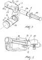
Figure 1 is a schematic axonometric view of an infusion pump for syringes according to the invention;Figure 2 is a schematic axonometric view of the pump ofFigure 1 without the covering and protective housing;Figure 3 is a schematic enlarged-scale axonometric view of a detail of the supporting means and of the first actuation means of the pump according to the invention;Figure 4 is a schematic top plan view of the detail ofFigure 4 ;Figure 5 is a schematic exploded view of the supporting means and of the first actuation means according to the invention;Figure 6 is a schematic axonometric enlarged-scale view of a detail of the means for locking the auxiliary syringe of the pump according to the invention.- With reference to the figures, the
reference numeral 1 generally designates an infusion pump for syringes. - The
pump 1 comprises a supportingstructure 2, which is divided into a base 2a and a housing 2b, means 3 for supporting asyringe 4, of the type constituted by acylindrical body 4a inside which aplunger 4b slides, which can be rigidly associated with thesyringe 4 and can be detachably associated with the supportingstructure 2 so as to rotate alternately about a first axis A that is substantially perpendicular to a second longitudinal axis B of thesyringe 4. - The
syringe 4, rigidly coupled to the support means 3, is therefore alternately rotated about the axis A with a so-called oscillating or rocking motion. - Further, the
pump 1 comprises first actuation means 5 of the automated type, for actuating the alternating rotation of the support or supportingmeans 3 and therefore of thesyringe 4 that is rigidly coupled thereto; said first actuation means cooperate functionally with second actuation means 6 of the automated type for actuating the sliding of theplunger 4b. - Conveniently, the axis A lies on a substantially horizontal plane, while the alternated rotation angle has a breadth of less than 2π rad.
- Further, the
pump 1 comprises means 7 for locking anauxiliary syringe 8, of the type that is constituted by acylindrical body 8a inside which aplunger 8b slides, said means being associated with the housing 2b, and third actuation means 9 of the automated type for actuating the sliding of theplunger 8b. - First sensing means 10 and second sensing means 11, such as for example on/off switches, detect the presence of the
syringe 4 and of theauxiliary syringe 8 respectively; first control means 12 and second control means 13 detect the sliding respectively of theplunger 4b and of theplunger 8b; and means 14 for sensing the pressure applied to theplungers - The second actuation means 6 and the third actuation means 9 are of the linear type.
- The first actuation means 5, the second actuation means 6 and the third actuation means 9 can be, for example, of the mechanical, pneumatic, hydraulic (hydrodynamic), electric or electromechanical type.
- The
pump 1 is provided with ON/OFF control means CM for activating and deactivating its operation, which are schematically shown in the figures cited above, can be advantageously operated with the feet, and are constituted for example by a pedal, a pushbutton or the like, for transmitting start and stop signals over a cable, wirelessly or via infrared carrier. - An electronic control and monitoring unit CU, such as an electric controller, advantageously of the programmable type, is functionally associated with the first actuation means 5, with the second actuation means 6, and optionally with the
first means 10 for sensing thesyringe 4, with the first control means 12 for controlling the sliding of theplunger 4b, with themeans 14 for sensing the pressure applied to theplunger 4b, and with the actuation means. - If the
auxiliary syringe 8 is also present, the electronic unit is also associated with the third actuation means 9, with thesecond means 11 for sensing theauxiliary syringe 8, with the second control means 13 for controlling the sliding of theplunger 8b, and with themeans 14 for sensing the pressure applied to theplunger 8b. - The first actuation means 5, may for example comprise a
shaft 15, which forms (extends along) the axis A and is supported, so that it can rotate, byfirst supports 16 formed in the base 2a of the supportingstructure 2, first motor means 17, which are associated with theshaft 15, and means 18 for coupling the support means 3 to theshaft 15. - Conveniently, the first motor means 17 are of the step motor type and comprise an inverter.
- The support means 3 comprise a
tubular element 19, inside which it is possible to insert thecylindrical body 4a of thesyringe 4; means for rigidly fixing thetubular element 19 to thecylindrical body 4a, for example of the interlocking, adhesive-bonding, or interference-coupling type, are provided. - In a particular embodiment, not shown, the fixing means may comprise a longitudinal cut, which interrupts the continuity of the
tubular element 19, the inside diameter of which, in the configuration in which it is disengaged from thecylindrical body 4a, is substantially smaller than the outside diameter of said cylindrical body. - The coupling means 18 can be of the interlocking and/or contrast and/or friction type; they comprise for example a
receptacle 20 for containing the support means 3, which is formed in theshaft 15 and is provided withcavities 21 in which it is possible to insertcorresponding protrusions 22 formed in the support means 3. - Advantageously, the
containment receptacle 20 has a profile that substantially duplicates the profile of the outer lateral surface of the support means 3. - Further, the support means 3 comprise a
contoured portion 23 that has a contoured profile P, which is suitable to mate with the likewise contoured head 24a of astem 24 that is inserted so that it can slide axially, with the interposition ofelastic means 25, in aguide 26 that is formed at the free end of theshaft 15 at thecontainment receptacle 20; the head 24a protrudes within thecontainment receptacle 20 in order to mate with theportion 23 and push, by way of the reaction of the elastic means 25, against the support means 3 so as to fix them to theshaft 15. - The
stem 24 has an end 24b, arranged opposite the head 24a, which protrudes externally from the free end of theshaft 15, proximate to which the first sensing means 10 are arranged; said sensing means are supported by aplate 27, which is fixed to the correspondingfirst support 16. - Insertion of the support means 3 in the
containment receptacle 20 produces the sliding of thestem 24 toward the outside of theshaft 15, so that the end 24b acts on the first sensing means 10, which being thus activated report the presence of the support means 3 and therefore of thesyringe 4 rigidly coupled thereto. - Each one of the second actuation means 6 and of the third actuation means 9 comprises straight guiding
means 28, along which aslider 30 is associated so that it can slide alternately by way ofbushes 29; ascrew 31, which is substantially parallel to the straight guidingmeans 28 and is supported so that it can rotate bysecond supports 32 formed in the base 2a of the supportingstructure 2 and is coupled to afemale thread 33 formed in theslider 30, and second motor means 34, which are associated with thescrew 31. - The
slider 30 rigidly supports the end of abar 35; apusher 36 is fixed to the opposite end of said bar and is suitable to make contact with theplunger syringe 4 and of theauxiliary syringe 8. - Conveniently, the second motor means 34 are of the step motor type and comprise an inverter.
- The pressure sensing means 14, constituted for example by a load cell, are fixed to the face of the
pusher 36 that makes contact with theplunger - The means 7 for locking the
auxiliary syringe 8 may be constituted for example by a receptacle, such as aslot 37 formed in ablock 38 that is fixed to the housing 2b, inside which it is possible to insert thewings 39 formed at the inlet end of thecylindrical body 8a, and aclamp 40 for locking thecylindrical body 8a. - The first control means 12 and the second control means 13 comprise
respective proximity sensors 41, switches or the like, which are suitable to detect the position of thecorresponding slider 30 and/orsensors 42 for detecting the rotation of thecorresponding screw 31. - A
keypad 43 and adisplay 44 anchored to the housing 2b allow to select/set and monitor the operating program of thepump 1. - With particular but not exclusive reference to the case in which the
pump 1, which comprises not only themeans 3 for supporting thesyringe 4 but also the means 7 for locking theauxiliary syringe 8, is used to perform sonograms with a contrast medium (echocontrast sonograms), the operation of the invention is as follows. - The echocontrast sonogram technique provides for the infusion in succession of a contrast medium that contains gas microbubbles and of a physiological solution, in quantities, with rates and with a time interval between the first infusion and the second infusion that can vary according to the type of diagnosis to be performed and according to the physical characteristics of the individual patient (weight, age, et cetera).
- The
syringe 4, to which the support means 3 are already rigidly anchored, and which is filled with a preset quantity of contrast medium, and theauxiliary syringe 8, filled with a preset quantity of physiological solution, are drained manually, the term "draining" being understood to designate the action meant to eliminate any residues of air contained in said syringes. - Once the operating program has been selected by means of the
keypad 43, the twosyringes pump 1; in particular, the support means 3 are rigidly coupled to theshaft 15, while thecylindrical body 8a of thesyringe 8 is anchored to the housing 2b by way of the locking means 7. - The first sensing means 10 and the second sensing means 11 report the presence of the
syringe 4 and of theauxiliary syringe 8, respectively, to the electronic control and monitoring unit. - The outlets of the two
syringes - By means of a command imparted from the
keypad 43, theshaft 15 is actuated by the first motor means 17 so as to rotate alternately about the axis A through a preset angle, as shown by the arrows F; the microbubbles of the contrast medium contained in thesyringe 4 are thus mixed uniformly and distributed within it. - After a time interval that can be preset, the electronic unit stops the first motor means 17 and starts the second actuation means 6 and the third actuation means 9 to drain the infusion line, the outlet of which is not yet connected to the duct for feeding to the patient.
- Once draining of the infusion line has ended and once its outlet has been connected to the duct for feeding to a patient, the electronic unit automatically restarts the first motor means 17 for another period of time during which the microbubbles of the contrast medium contained in the
syringe 4, which is rotated alternately about the axis A with an oscillating motion, are mixed and distributed uniformly inside it, thepusher 36 of the second actuation means 6 being moved away beforehand from theplunger 4b. - The medical personnel assigned to performing the sonogram, at its own discretion and despite having both hands occupied in operating the sonogram probe and in managing the processing of the images that it transmits to a monitor, then activates, by acting with a foot on the pedal, the operation of the
pump 1 to infuse the contrast medium and then automatically infuse the physiological solution without further interventions of any health personnel. - Once this time interval has elapsed, the electronic unit starts the second motor means 34 of the second actuation means 6 in order to infuse the contrast medium, as shown by the arrow G; end of the infusion is reported by the
sensors 41, which report to the electronic unit that the stroke limit has been reached by the correspondingslider 30. - Once the second motor means 34 of the second actuation means 6 have stopped, the electronic unit starts the second motor means 34 of the third actuation means 9 in order to infuse in succession the physiological solution, as shown by the arrow H; as before, the end of this second infusion is reported by the corresponding
sensors 41, which report to the electronic unit that the stroke limit has been reached by the correspondingslider 30. - Finally, the electronic unit reverses the rotation of the second motor means 34 and of the second and third actuation means 6 and 9 in order to return the
corresponding pushers 36 to the beginning of their stroke, as shown by the arrows L. - It should be noted that the initial position of the two
plungers rotation sensors 42; the former report the contact pressure with theplungers - The pressure sensing means 14 further allow to detect, during infusion, any abnormal increase in pressure on the
plungers - This technique can be used for diagnosis for example in cardiology, neurology, gastroenterology, or for targeted therapeutic treatments.
- The operation of the
pump 1 in possible different applications can be deduced easily by the person skilled in the art; it can be used whenever it is necessary to mix the components of a fluid to be infused. - In practice it has been found that the described invention achieves the intended aim and objects.
- The pump according to the invention in fact allows to automate not only the draining and infusion but also the mixing of the fluid to be infused, to mix said fluid homogeneously, precisely and in a short time without the intervention of auxiliary health personnel, and this accordingly entails a containment of labor costs and of wastes of material, and allows medical personnel to perform mixing and infusion automatically and autonomously.
- Finally, it should be noted that the alternated rotation of the syringe that contains the fluid to be mixed about an axis that is substantially perpendicular to the longitudinal axis of said syringe causes the shaking and entrainment of said fluid between the two ends of said syringe, and this ensures uniform mixing, which instead cannot be obtained if the rotation of the syringe occurs about the longitudinal axis thereof; due to the low viscosity of the fluids that are normally used, they in fact would not be entrained in rotation and therefore would not be stirred correctly.
- The invention thus conceived is susceptible of numerous modifications and variations, all of which are within the scope of the appended claims.
- In practice, the materials used, as well as the shapes and the dimensions, may be any according to requirements without thereby abandoning the scope of the protection of the appended claim.
- Where technical features mentioned in any claim are followed by reference signs, those reference signs have been included for the sole purpose of increasing the intelligibility of the claims and accordingly, such reference signs do not have any limiting effect on the interpretation of each element identified by way of example by such reference signs.
Claims (14)
- A infusion pump for syringes, comprising a supporting structure (2),
means (3) for supporting a syringe (4) that are rigidly associable with said syringe (4) and are associated with said supporting structure (2) so that they can rotate alternately about an axis (A) that is substantially perpendicular to the longitudinal axis (B) of said syringe, said supporting means (3) comprising a tubular element (19), inside which is insertable the cylindrical body (4a) of said syringe (4) and means for fixing said tubular element (19) that is rigidly coupled to said cylindrical body (4a) of the syringe (4),
first means (5) for actuating said alternating rotation and comprising a shaft (15), which forms said perpendicular axis (A) and is supported so that it can rotate by said supporting structure (2), first motor means (17) associated with said shaft (15) and means (18) for coupling said supporting means (3) to said shaft (15)
and second means (6) for actuating the sliding of the plunger (4b) of said syringe (4), which cooperate functionally with said first actuation means (5) and comprising a bar (35) and a pusher (36) fixed to one end of said bar (35) and suitable to contact the plunger (4b) of the syringe (4),
characterized in that it comprises an electronic control and monitoring unit (CU) which is functionally associated with said first and second actuating means (5, 6) to actuate said first motor means (17) so as to rotate alternately said shaft (15) about the axis (A) through a preset angle, and to actuate said second actuation means (6) to move the pusher (36) of said second actuation means (6) away beforehand from the plunger (4b), and to stop, after a time interval that can be preset, said first motor means (17) and start said second actuation means (6). - The pump according to claim 1,characterized in that said perpendicular axis (A) lies on a substantially horizontal plane.
- The pump according to claim 1 or 2,characterized in that the angle of said alternating rotation is less than 2πrad.
- The pump according to one or more of the preceding claims,characterized in that it comprises means (7) for locking an auxiliary syringe (8), which are associated with said supporting structure (2), and third means (9) for actuating the sliding of the plunger of said auxiliary syringe.
- The pump according to one or more of the preceding claims,characterized in that it comprises first means (10) for sensing said syringe (4) and/or second means (11) for sensing said auxiliary syringe (8).
- The pump according to one or more of the preceding claims,characterized in that it comprises first means (12) for controlling sliding of the plunger (4b) of said syringe (4).
- The pump according to one or more of the preceding claims from 4 to 6,characterized in that it comprises second means (13) for controlling sliding of the plunger (8b) of said auxiliary syringe (8).
- The pump according to one or more of the preceding claims,characterized in that at least one of said second and third actuation means (5, 6, 9) comprises means (14) for sensing the pressure applied to the plunger (4b, 8b) of said syringe (4) and of said auxiliary syringe (8), respectively.
- The pump according to one or more of the preceding claims,characterized in that the electronic control and monitoring unit (CU) is functionally associated with at least said first and second actuation means (5, 6, 9).
- The pump according to one or more of the preceding claims,characterized in that said supporting means (3) comprise a portion (23) that has a contoured profile (P) and is suitable to mate with the head (24a) of a stem (24) that is inserted so as to be axially slidable, with the interposition of elastic means (25), in a guide (26) formed in said shaft (15) at a containment receptacle (20) of said shaft (15) said head (24a) protruding into said containment receptacle (20), the coupling between said head (24a) and said contoured portion (23) being suitable to fix said supporting means (3) to said shaft (15).
- The pump according to one or more of claim 5 or claims 6 to 10 when dependent upon claim 5,
characterized in that said first sensing means (10) are associated with
said shaft (15). - The pump according to claim 10 as dependent upon claim 5 or claim 11 as dependent upon claim 10,characterized in that the end (24b) of said stem (24) that lies opposite said head (24a) protrudes externally from said shaft (15), said first sensing means (10) being arranged proximate thereto, said stem (24) being suitable to actuate said first sensing means (10).
- The pump according to one or more of the claims 4-13,characterized in that at least one of said second and third actuation means (6, 9) comprises straight guiding means (28), along which a slider (30) is associated so that it can slide alternately; a screw (31), which is substantially parallel to said straight guiding means (28) and is supported so that it can rotate by said supporting structure (2) and is coupled to a female thread (33) formed in said slider (30); second motor means (34), which are associated with said screw (31); and a pusher (36), which is rigidly associated with said slider (30) and is suitable to make contact with the plunger (4b, 8b) of said syringe (4) or of said auxiliary syringe (8), respectively.
- The pump according to one or more of the claims 4-13,characterized in that said locking means (7) comprise a receptacle (37, 38) for accommodating the wings (3a) formed at the inlet end of said cylindrical body (8a) of the auxiliary syringe (8) and a clamp (40) for locking said cylindrical body (8a).
Priority Applications (2)
| Application Number | Priority Date | Filing Date | Title |
|---|---|---|---|
| SI200532149ASI1561483T1 (en) | 2004-02-06 | 2005-01-28 | Infusion pump for syringes |
| PL05001849TPL1561483T3 (en) | 2004-02-06 | 2005-01-28 | Infusion pump for syringes |
Applications Claiming Priority (2)
| Application Number | Priority Date | Filing Date | Title |
|---|---|---|---|
| IT000028AITMO20040028A1 (en) | 2004-02-06 | 2004-02-06 | SYRINGE INFUSION PUMP |
| ITMO20040028 | 2004-02-06 |
Publications (2)
| Publication Number | Publication Date |
|---|---|
| EP1561483A1 EP1561483A1 (en) | 2005-08-10 |
| EP1561483B1true EP1561483B1 (en) | 2017-03-15 |
Family
ID=34674575
Family Applications (1)
| Application Number | Title | Priority Date | Filing Date |
|---|---|---|---|
| EP05001849.8AExpired - LifetimeEP1561483B1 (en) | 2004-02-06 | 2005-01-28 | Infusion pump for syringes |
Country Status (9)
| Country | Link |
|---|---|
| US (1) | US7347837B2 (en) |
| EP (1) | EP1561483B1 (en) |
| ES (1) | ES2625071T3 (en) |
| HU (1) | HUE032302T2 (en) |
| IT (1) | ITMO20040028A1 (en) |
| LT (1) | LT1561483T (en) |
| PL (1) | PL1561483T3 (en) |
| PT (1) | PT1561483T (en) |
| SI (1) | SI1561483T1 (en) |
Families Citing this family (25)
| Publication number | Priority date | Publication date | Assignee | Title |
|---|---|---|---|---|
| WO2004094823A2 (en) | 2003-04-23 | 2004-11-04 | Biovalve Technologies, Inc. | Hydraulically actuated pump for long duration medicament administration |
| DE102004031673B4 (en)* | 2004-06-30 | 2009-04-16 | Erbe Elektromedizin Gmbh | Medical pump |
| DE102004031674B3 (en)* | 2004-06-30 | 2005-08-04 | Erbe Elektromedizin Gmbh | Medical pump for a water jet in liver surgery comprises a drive unit for opening and closing holders and/or coupling units |
| US9089636B2 (en) | 2004-07-02 | 2015-07-28 | Valeritas, Inc. | Methods and devices for delivering GLP-1 and uses thereof |
| WO2007115039A2 (en) | 2006-03-30 | 2007-10-11 | Valeritas, Llc | Multi-cartridge fluid delivery device |
| WO2008153985A1 (en)* | 2007-06-11 | 2008-12-18 | Numia Medical Technology, Llc | Syringe infusion pump |
| WO2009076429A2 (en) | 2007-12-10 | 2009-06-18 | Medrad, Inc. | Continuous fluid delivery system and method |
| US8105269B2 (en) | 2008-10-24 | 2012-01-31 | Baxter International Inc. | In situ tubing measurements for infusion pumps |
| US8137083B2 (en) | 2009-03-11 | 2012-03-20 | Baxter International Inc. | Infusion pump actuators, system and method for controlling medical fluid flowrate |
| US8382447B2 (en) | 2009-12-31 | 2013-02-26 | Baxter International, Inc. | Shuttle pump with controlled geometry |
| CN102933241A (en)* | 2010-04-06 | 2013-02-13 | 株式会社根本杏林堂 | Medical liquid injection device |
| US8567235B2 (en) | 2010-06-29 | 2013-10-29 | Baxter International Inc. | Tube measurement technique using linear actuator and pressure sensor |
| TR201808306T4 (en)* | 2011-05-25 | 2018-07-23 | Sanofi Aventis Deutschland | A cartridge holder, a medical device comprising such a cartridge holder, and a method for inserting a medical drug reservoir. |
| DE102011081137B4 (en)* | 2011-08-17 | 2015-03-12 | Henkel Ag & Co. Kgaa | output system |
| WO2016089572A1 (en)* | 2014-12-02 | 2016-06-09 | Smiths Medical Asd, Inc. | Syringe infusion pump security |
| US10507319B2 (en) | 2015-01-09 | 2019-12-17 | Bayer Healthcare Llc | Multiple fluid delivery system with multi-use disposable set and features thereof |
| JP6406706B2 (en)* | 2015-02-05 | 2018-10-17 | 公立大学法人奈良県立医科大学 | Syringe rotating device |
| WO2017066262A1 (en)* | 2015-10-12 | 2017-04-20 | Swaminathan Jayaraman | System and method for delivery of a therapeutic agent through a catheter |
| US11235296B2 (en) | 2015-12-29 | 2022-02-01 | Bracco Suisse Sa | Method and device of making a suspension of microparticles homogeneously distributed in an aqueous liquid carrier |
| KR20170089053A (en)* | 2016-01-25 | 2017-08-03 | 삼성전자주식회사 | Resin coating apparatus and method of manufacturing light emitting device package using the same |
| CN109745906A (en)* | 2019-02-21 | 2019-05-14 | 深圳供电局有限公司 | Support for needle cylinder and mechanical oscillator |
| US12048830B2 (en) | 2019-03-07 | 2024-07-30 | Kpr U.S., Llc | Delivery of fluid from a syringe |
| CN110215572B (en)* | 2019-06-20 | 2021-07-23 | 纳智医疗设备(徐州)有限公司 | Syringe positioning mechanism for syringe pump |
| US12318528B2 (en) | 2020-10-30 | 2025-06-03 | Mozarc Medical Us Llc | Variable orifice fistula graft |
| CN113694313B (en)* | 2021-08-16 | 2023-08-08 | 南京智慧阳光科技有限公司 | Medical injection quantitative device for neurology operation |
Family Cites Families (10)
| Publication number | Priority date | Publication date | Assignee | Title |
|---|---|---|---|---|
| US3631847A (en)* | 1966-03-04 | 1972-01-04 | James C Hobbs | Method and apparatus for injecting fluid into the vascular system |
| US4585009A (en)* | 1983-02-28 | 1986-04-29 | E. R. Squibb & Sons, Inc. | Strontium-rubidium infusion pump with in-line dosimetry |
| US4838857A (en)* | 1985-05-29 | 1989-06-13 | Becton, Dickinson And Company | Medical infusion device |
| US5814015A (en)* | 1995-02-24 | 1998-09-29 | Harvard Clinical Technology, Inc. | Infusion pump for at least one syringe |
| US6221045B1 (en)* | 1995-04-20 | 2001-04-24 | Acist Medical Systems, Inc. | Angiographic injector system with automatic high/low pressure switching |
| JP2000513967A (en)* | 1996-07-01 | 2000-10-24 | フアーマシア・アンド・アツプジヨン・アー・ベー | Distributing apparatus and operating method thereof |
| US6575930B1 (en)* | 1999-03-12 | 2003-06-10 | Medrad, Inc. | Agitation devices and dispensing systems incorporating such agitation devices |
| WO2001008727A1 (en)* | 1999-07-30 | 2001-02-08 | Medrad, Inc. | Injector systems and syringe adapters for use therewith |
| AU2001271347A1 (en)* | 2000-06-22 | 2002-01-02 | The Research Foundation Of The State University Ofnew York At Buffalo | Micro-injection pump |
| US6821013B2 (en)* | 2001-12-20 | 2004-11-23 | Medrad, Inc. | Adapters, adapter systems and method for use in connection with powered injectors for agitation of multi-component fluids |
- 2004
- 2004-02-06ITIT000028Apatent/ITMO20040028A1/enunknown
- 2005
- 2005-01-28PTPT50018498Tpatent/PT1561483T/enunknown
- 2005-01-28EPEP05001849.8Apatent/EP1561483B1/ennot_activeExpired - Lifetime
- 2005-01-28HUHUE05001849Apatent/HUE032302T2/enunknown
- 2005-01-28SISI200532149Apatent/SI1561483T1/enunknown
- 2005-01-28ESES05001849.8Tpatent/ES2625071T3/ennot_activeExpired - Lifetime
- 2005-01-28LTLTEP05001849.8Tpatent/LT1561483T/enunknown
- 2005-01-28PLPL05001849Tpatent/PL1561483T3/enunknown
- 2005-02-07USUS11/050,836patent/US7347837B2/ennot_activeExpired - Lifetime
Non-Patent Citations (1)
| Title |
|---|
| None* |
Also Published As
| Publication number | Publication date |
|---|---|
| US20050177109A1 (en) | 2005-08-11 |
| HUE032302T2 (en) | 2017-09-28 |
| ITMO20040028A1 (en) | 2004-05-06 |
| SI1561483T1 (en) | 2017-07-31 |
| PT1561483T (en) | 2017-06-05 |
| LT1561483T (en) | 2017-06-26 |
| US7347837B2 (en) | 2008-03-25 |
| EP1561483A1 (en) | 2005-08-10 |
| PL1561483T3 (en) | 2017-08-31 |
| ES2625071T3 (en) | 2017-07-18 |
Similar Documents
| Publication | Publication Date | Title |
|---|---|---|
| EP1561483B1 (en) | Infusion pump for syringes | |
| EP2229199B1 (en) | Power injector having patency check with pressure monitoring | |
| EP2222357B1 (en) | Power injector with ram retraction | |
| EP2283884B1 (en) | Fluid delivery system with multi-dose fluid source | |
| CA2725252C (en) | Power injector with keep vein open functionality | |
| EP2316507A2 (en) | Power injector with status messaging | |
| JP5597138B2 (en) | Power injector with flow rate evaluation | |
| KR20190109475A (en) | Injector system and syringe adapter for use with it | |
| JP6817644B2 (en) | Injection device and control device for injection device | |
| EP2376146A2 (en) | Multi-dose injection system | |
| WO2007124275A2 (en) | Fluid delivery system with pump cassette | |
| JP5468456B2 (en) | Chemical injection device | |
| TR201807574T4 (en) | A system for medical treatment. | |
| JP2012501221A (en) | Electric injector with calibration pressure monitoring function | |
| EP2579917B1 (en) | A device for simultaneous infusion of drugs into multiple infusion sites | |
| RU2750676C1 (en) | Method and devices for injection of insulin | |
| EP1561488B1 (en) | Device for locking syringes to infusion pumps | |
| KR20250096767A (en) | Large-volume drug delivery device |
Legal Events
| Date | Code | Title | Description |
|---|---|---|---|
| PUAI | Public reference made under article 153(3) epc to a published international application that has entered the european phase | Free format text:ORIGINAL CODE: 0009012 | |
| AK | Designated contracting states | Kind code of ref document:A1 Designated state(s):AT BE BG CH CY CZ DE DK EE ES FI FR GB GR HU IE IS IT LI LT LU MC NL PL PT RO SE SI SK TR | |
| AX | Request for extension of the european patent | Extension state:AL BA HR LV MK YU | |
| 17P | Request for examination filed | Effective date:20060203 | |
| AKX | Designation fees paid | Designated state(s):AT BE BG CH CY CZ DE DK EE ES FI FR GB GR HU IE IS IT LI LT LU MC NL PL PT RO SE SI SK TR | |
| 17Q | First examination report despatched | Effective date:20100608 | |
| RAP1 | Party data changed (applicant data changed or rights of an application transferred) | Owner name:SIDAM S.R.L. | |
| GRAP | Despatch of communication of intention to grant a patent | Free format text:ORIGINAL CODE: EPIDOSNIGR1 | |
| RIC1 | Information provided on ipc code assigned before grant | Ipc:B01F 9/00 20060101ALI20160830BHEP Ipc:B01F 11/00 20060101ALI20160830BHEP Ipc:A61M 5/145 20060101AFI20160830BHEP | |
| INTG | Intention to grant announced | Effective date:20161006 | |
| STAA | Information on the status of an ep patent application or granted ep patent | Free format text:STATUS: GRANT OF PATENT IS INTENDED | |
| GRAS | Grant fee paid | Free format text:ORIGINAL CODE: EPIDOSNIGR3 | |
| GRAA | (expected) grant | Free format text:ORIGINAL CODE: 0009210 | |
| STAA | Information on the status of an ep patent application or granted ep patent | Free format text:STATUS: THE PATENT HAS BEEN GRANTED | |
| AK | Designated contracting states | Kind code of ref document:B1 Designated state(s):AT BE BG CH CY CZ DE DK EE ES FI FR GB GR HU IE IS IT LI LT LU MC NL PL PT RO SE SI SK TR | |
| REG | Reference to a national code | Ref country code:CH Ref legal event code:EP Ref country code:GB Ref legal event code:FG4D | |
| REG | Reference to a national code | Ref country code:IE Ref legal event code:FG4D | |
| REG | Reference to a national code | Ref country code:AT Ref legal event code:REF Ref document number:874913 Country of ref document:AT Kind code of ref document:T Effective date:20170415 | |
| REG | Reference to a national code | Ref country code:DE Ref legal event code:R096 Ref document number:602005051503 Country of ref document:DE | |
| REG | Reference to a national code | Ref country code:DK Ref legal event code:T3 Effective date:20170522 | |
| REG | Reference to a national code | Ref country code:PT Ref legal event code:SC4A Ref document number:1561483 Country of ref document:PT Date of ref document:20170605 Kind code of ref document:T Free format text:AVAILABILITY OF NATIONAL TRANSLATION Effective date:20170524 | |
| REG | Reference to a national code | Ref country code:RO Ref legal event code:EPE | |
| REG | Reference to a national code | Ref country code:CH Ref legal event code:NV Representative=s name:IPWAY DI FRANCESCO FABIO AND CO., CH | |
| REG | Reference to a national code | Ref country code:NL Ref legal event code:FP | |
| REG | Reference to a national code | Ref country code:SE Ref legal event code:TRGR | |
| REG | Reference to a national code | Ref country code:EE Ref legal event code:FG4A Ref document number:E013731 Country of ref document:EE Effective date:20170519 | |
| REG | Reference to a national code | Ref country code:ES Ref legal event code:FG2A Ref document number:2625071 Country of ref document:ES Kind code of ref document:T3 Effective date:20170718 | |
| REG | Reference to a national code | Ref country code:HU Ref legal event code:AG4A Ref document number:E032302 Country of ref document:HU | |
| REG | Reference to a national code | Ref country code:SK Ref legal event code:T3 Ref document number:E 24416 Country of ref document:SK | |
| REG | Reference to a national code | Ref country code:GR Ref legal event code:EP Ref document number:20170401629 Country of ref document:GR Effective date:20171122 | |
| PG25 | Lapsed in a contracting state [announced via postgrant information from national office to epo] | Ref country code:IS Free format text:LAPSE BECAUSE OF FAILURE TO SUBMIT A TRANSLATION OF THE DESCRIPTION OR TO PAY THE FEE WITHIN THE PRESCRIBED TIME-LIMIT Effective date:20170715 | |
| REG | Reference to a national code | Ref country code:DE Ref legal event code:R097 Ref document number:602005051503 Country of ref document:DE | |
| PLBE | No opposition filed within time limit | Free format text:ORIGINAL CODE: 0009261 | |
| STAA | Information on the status of an ep patent application or granted ep patent | Free format text:STATUS: NO OPPOSITION FILED WITHIN TIME LIMIT | |
| REG | Reference to a national code | Ref country code:FR Ref legal event code:PLFP Year of fee payment:14 | |
| 26N | No opposition filed | Effective date:20171218 | |
| REG | Reference to a national code | Ref country code:AT Ref legal event code:UEP Ref document number:874913 Country of ref document:AT Kind code of ref document:T Effective date:20170315 | |
| PG25 | Lapsed in a contracting state [announced via postgrant information from national office to epo] | Ref country code:CY Free format text:LAPSE BECAUSE OF FAILURE TO SUBMIT A TRANSLATION OF THE DESCRIPTION OR TO PAY THE FEE WITHIN THE PRESCRIBED TIME-LIMIT Effective date:20170315 | |
| P01 | Opt-out of the competence of the unified patent court (upc) registered | Effective date:20230527 | |
| PGFP | Annual fee paid to national office [announced via postgrant information from national office to epo] | Ref country code:NL Payment date:20240126 Year of fee payment:20 | |
| PGFP | Annual fee paid to national office [announced via postgrant information from national office to epo] | Ref country code:LU Payment date:20240129 Year of fee payment:20 | |
| PGFP | Annual fee paid to national office [announced via postgrant information from national office to epo] | Ref country code:GR Payment date:20240126 Year of fee payment:20 | |
| PGFP | Annual fee paid to national office [announced via postgrant information from national office to epo] | Ref country code:LT Payment date:20240103 Year of fee payment:20 | |
| PGFP | Annual fee paid to national office [announced via postgrant information from national office to epo] | Ref country code:ES Payment date:20240201 Year of fee payment:20 Ref country code:IE Payment date:20240129 Year of fee payment:20 | |
| PGFP | Annual fee paid to national office [announced via postgrant information from national office to epo] | Ref country code:AT Payment date:20240104 Year of fee payment:20 | |
| PGFP | Annual fee paid to national office [announced via postgrant information from national office to epo] | Ref country code:MC Payment date:20240105 Year of fee payment:20 | |
| PGFP | Annual fee paid to national office [announced via postgrant information from national office to epo] | Ref country code:RO Payment date:20240105 Year of fee payment:20 Ref country code:HU Payment date:20240111 Year of fee payment:20 Ref country code:FI Payment date:20240125 Year of fee payment:20 Ref country code:EE Payment date:20240104 Year of fee payment:20 Ref country code:DE Payment date:20240129 Year of fee payment:20 Ref country code:CZ Payment date:20240109 Year of fee payment:20 Ref country code:BG Payment date:20240129 Year of fee payment:20 Ref country code:CH Payment date:20240201 Year of fee payment:20 Ref country code:GB Payment date:20240129 Year of fee payment:20 Ref country code:PT Payment date:20240115 Year of fee payment:20 Ref country code:SK Payment date:20240103 Year of fee payment:20 | |
| PGFP | Annual fee paid to national office [announced via postgrant information from national office to epo] | Ref country code:SI Payment date:20240104 Year of fee payment:20 | |
| PGFP | Annual fee paid to national office [announced via postgrant information from national office to epo] | Ref country code:TR Payment date:20240122 Year of fee payment:20 Ref country code:SE Payment date:20240127 Year of fee payment:20 Ref country code:PL Payment date:20240102 Year of fee payment:20 Ref country code:IT Payment date:20240122 Year of fee payment:20 Ref country code:FR Payment date:20240125 Year of fee payment:20 Ref country code:DK Payment date:20240125 Year of fee payment:20 Ref country code:BE Payment date:20240129 Year of fee payment:20 | |
| REG | Reference to a national code | Ref country code:DE Ref legal event code:R071 Ref document number:602005051503 Country of ref document:DE | |
| REG | Reference to a national code | Ref country code:NL Ref legal event code:MK Effective date:20250127 | |
| REG | Reference to a national code | Ref country code:CH Ref legal event code:PL | |
| REG | Reference to a national code | Ref country code:DK Ref legal event code:EUP Expiry date:20250128 | |
| REG | Reference to a national code | Ref country code:ES Ref legal event code:FD2A Effective date:20250204 | |
| REG | Reference to a national code | Ref country code:LT Ref legal event code:MM9A Effective date:20250128 | |
| REG | Reference to a national code | Ref country code:SK Ref legal event code:MK4A Ref document number:E 24416 Country of ref document:SK Expiry date:20250128 | |
| REG | Reference to a national code | Ref country code:GB Ref legal event code:PE20 Expiry date:20250127 | |
| REG | Reference to a national code | Ref country code:IE Ref legal event code:MK9A | |
| REG | Reference to a national code | Ref country code:SE Ref legal event code:EUG | |
| REG | Reference to a national code | Ref country code:AT Ref legal event code:MK07 Ref document number:874913 Country of ref document:AT Kind code of ref document:T Effective date:20250128 | |
| REG | Reference to a national code | Ref country code:BE Ref legal event code:MK Effective date:20250128 | |
| PG25 | Lapsed in a contracting state [announced via postgrant information from national office to epo] | Ref country code:PT Free format text:LAPSE BECAUSE OF EXPIRATION OF PROTECTION Effective date:20250206 | |
| PG25 | Lapsed in a contracting state [announced via postgrant information from national office to epo] | Ref country code:ES Free format text:LAPSE BECAUSE OF EXPIRATION OF PROTECTION Effective date:20250129 | |
| PG25 | Lapsed in a contracting state [announced via postgrant information from national office to epo] | Ref country code:IE Free format text:LAPSE BECAUSE OF EXPIRATION OF PROTECTION Effective date:20250128 | |
| PG25 | Lapsed in a contracting state [announced via postgrant information from national office to epo] | Ref country code:CZ Free format text:LAPSE BECAUSE OF EXPIRATION OF PROTECTION Effective date:20250128 | |
| PG25 | Lapsed in a contracting state [announced via postgrant information from national office to epo] | Ref country code:GB Free format text:LAPSE BECAUSE OF EXPIRATION OF PROTECTION Effective date:20250127 Ref country code:SK Free format text:LAPSE BECAUSE OF EXPIRATION OF PROTECTION Effective date:20250128 |