EP1559170B1 - Reader or transmitter and/or receiver comprising a shrouded antenna - Google Patents
Reader or transmitter and/or receiver comprising a shrouded antennaDownload PDFInfo
- Publication number
- EP1559170B1 EP1559170B1EP02787538.4AEP02787538AEP1559170B1EP 1559170 B1EP1559170 B1EP 1559170B1EP 02787538 AEP02787538 AEP 02787538AEP 1559170 B1EP1559170 B1EP 1559170B1
- Authority
- EP
- European Patent Office
- Prior art keywords
- coils
- group
- turns
- antenna
- coil
- Prior art date
- Legal status (The legal status is an assumption and is not a legal conclusion. Google has not performed a legal analysis and makes no representation as to the accuracy of the status listed.)
- Expired - Lifetime
Links
- 230000010363phase shiftEffects0.000claimsdescription16
- 230000007423decreaseEffects0.000claimsdescription6
- 230000003247decreasing effectEffects0.000claimsdescription3
- 238000010586diagramMethods0.000description2
Images


Classifications
- H—ELECTRICITY
- H01—ELECTRIC ELEMENTS
- H01Q—ANTENNAS, i.e. RADIO AERIALS
- H01Q1/00—Details of, or arrangements associated with, antennas
- H01Q1/12—Supports; Mounting means
- H01Q1/22—Supports; Mounting means by structural association with other equipment or articles
- H—ELECTRICITY
- H01—ELECTRIC ELEMENTS
- H01Q—ANTENNAS, i.e. RADIO AERIALS
- H01Q1/00—Details of, or arrangements associated with, antennas
- H01Q1/12—Supports; Mounting means
- H01Q1/22—Supports; Mounting means by structural association with other equipment or articles
- H01Q1/2208—Supports; Mounting means by structural association with other equipment or articles associated with components used in interrogation type services, i.e. in systems for information exchange between an interrogator/reader and a tag/transponder, e.g. in Radio Frequency Identification [RFID] systems
- H01Q1/2216—Supports; Mounting means by structural association with other equipment or articles associated with components used in interrogation type services, i.e. in systems for information exchange between an interrogator/reader and a tag/transponder, e.g. in Radio Frequency Identification [RFID] systems used in interrogator/reader equipment
- H—ELECTRICITY
- H01—ELECTRIC ELEMENTS
- H01Q—ANTENNAS, i.e. RADIO AERIALS
- H01Q7/00—Loop antennas with a substantially uniform current distribution around the loop and having a directional radiation pattern in a plane perpendicular to the plane of the loop
- H01Q7/04—Screened antennas
Definitions
- the present inventionrelates to a reader or transmitter equipped with a shielded antenna.
- the inventionrelates to such a device provided for communicating with transponders placed inside a communication volume defined by the antenna, in particular by the geometric dimensions thereof.
- the communication volumeis provided inside a rectangular cylinder or parallelepiped around which the antenna is arranged.
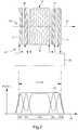
- a central coil 2defining inside its turns 4 a communication volume 6 and, on either side of this coil 2, two shielding coils 8 and 9.
- the coils 8 and 9are arranged at a certain distance from the coil 2.
- the coils 8 and 9are supplied with a phase shift of 180 ° relative to the central communication coil.
- a sharp decrease in the amplitude of the field of the shielded antennaoccurs between the three regions dominated by the respective fields of the three coils considered.
- regions 11 and 12 for decreasing the amplitude of the magnetic fieldthus result from the aforementioned 180 ° phase shift for feeding the shielding coils.
- the decrease in the magnetic fieldis relatively large, so that communication between the reader or transmitter transponders can be assured in these regions. Therefore, the active area ZA of the shielded antenna shown in FIG. figure 1 is limited within the geometrical dimensions of the coil 2. This represents a major disadvantage for such a device.
- the shielded antenna of the prior art according to the figure 1has a useful communication volume of a relatively small length ZA with respect to the total length L of the shielded antenna.
- An object of the present inventionis to overcome the major disadvantage mentioned above by providing a reader or transmitter with a shielded antenna whose useful area of communication substantially corresponds to the total length of the shielded antenna.
- the document WO9638877 A1discloses an article surveillance system comprising a plurality of coils.
- the inventionrelates to a reader or transmitter intended to communicate with transponders whose antenna is formed of several turns defining a central axis and a global interior volume, characterized in that this antenna comprises a first group of turns forming at least two first coils and a second group of turns forming two second coils, these first and second coils being supplied in phase quadrature and arranged to generate a communication field with an approximately constant amplitude on substantially the entire length of said antenna along its central axis and decreasing rapidly outside this antenna away from it.
- the shielded antenna of the prior art shown in FIG. figure 1by incorporating two compensation coils between the central coil and respectively the two end coils, these two compensation coils being supplied with a phase shift of 90 ° relative to the other three coils.
- These two compensation coilsare supplied with a phase shift of 180 ° between them, so as to quickly cancel their resulting field out of the antenna, and are arranged relative to the first three coils shown in FIG. figure 1 in order to compensate for the decrease of the magnetic field in the regions 11 and 12, ie between the central coil 2 and the end coils 8 and 9.
- FIG. 1a first embodiment of the invention.
- the coils 8 and 9are fed by the power supply and control means 20 of the reader 22 with a phase shift of 180 ° relative to the central coil 6.
- the coils 16 and 17are fed one relative to the other with a phase shift also of 180 ° and with a phase shift of 90 ° relative to the other coils 6, 8 and 9.
- the two coils 16 and 17are arranged so that their magnetic field along the central axis 24 of the antenna 14 is maximum respectively in the two regions 11 and 12 where the resulting magnetic field for the three coils 6, 8 and 9 decreases or vanishes, as shown in the graph of FIG. figure 2 which shows these amplitudes of the magnetic field H along the central axis 24 of the antenna.
- Power phase shiftsare described by a cosine (Sin) and sin (Sin) supply with one of the two +/- arithmetic signs placed in front.
- each coil along the central axis 24 and the characteristics of each coilare determined so as to obtain a relatively constant amplitude of the magnetic field 30 within the volume 32 defined by the antenna, that is, that is to say by the set of coils defining a total length L on the axis 24.
- the shielding of the main antennathat is to say of the central antenna 6, is arranged in such a way that the overall volume defined by the set of coils provided constitutes the Useful volume of communication with transponders.
- the shieldingis integrated into the antenna itself. Inside this antenna, no significant reduction or cancellation of the magnetic field takes place along the active zone ZA, so that the reader according to the invention can communicate with any transponder situated inside the volume 32 defined by the set of coils forming the antenna.
- the cancellation of the magnetic field due to the counter-antennas fed with a phase shift of 180 °is compensated by the arrangement of coils fed in quadrature phase.
- the vector sum of all the fields generated by the set of coilscorresponds to a quadratic sum between the resulting field of the first group of coils 6, 8 and 9 and the resulting field of the second group of coils 16 and 17.
- Each coilis formed at least 1 turn.
- the first group of coilsconstitutes a first group of turns while the second group of coils constitutes a second group of turns.
- the two coils 16 and 17are supplied with a phase shift of 180 ° so as to ensure mutual shielding out of the antenna.
- the electrical diagram of the power supply of the coilsis given to the figure 4 .
- FIG. 3To the figure 3 is shown a variant of the arrangement of an antenna according to the invention.
- the position of the five coils 6, 8, 9, 16 and 17is shown schematically in the upper drawing.
- the central spool 6has 28 turns and extends along the axis 24 between -13.5 cm and 13.5 cm.
- the coils 8 and 9are each formed of 18 turns and are respectively at -70 cm and + 70 cm.
- these three coils of the first groupare traversed by a current of 1A.
- the two coils 16 and 17 of the second groupeach have 15 turns and are placed respectively at -30 cm and + 30 cm.
- the power supply of this second groupis provided with 1.57 A.
- FIG. 5schematically shows a second embodiment of the invention.
- the antenna 42is formed by only four coils, namely a first group consisting of coils 44 and 46 and a second group consisting of coils 48 and 50.
- the amplitudes 52 and 54 generated respectively by the first and the second group of coilsare represented.
- the resulting total magnetic fieldis given by curve 56 which corresponds to the quadratic sum of curves 52 and 54.
- the coils of the second groupare energized in quadrature phase relative to the coils of the first group.
- the two coils of the same groupare supplied with a phase shift of 180 ° so as to generate mutual shielding.
- the resulting amplitude 56 within the volume defined by the antenna 42is substantially constant but has a slight variation.
- this second embodimentallows the economy of a coil but must be satisfied with a certain variation of field within the volume of the antenna, that is to say the active zone ZA of communication with transponders.
- such a relatively small variation with respect to the amplitude of the magnetic field Hcan be considered substantially constant.
- the antenna 42is arranged as follows: the coil 46 extends from -70 cm to -39 cm and the coil 48 extends from -22 cm to 9 cm.
- the spool 44extends from -9 cm to 22 cm and the spool 50 extends from 39 cm to 70 cm. All the coils are formed of 15 turns and are powered by an electric current of 1 A. The amplitude curves given on the graph correspond to this numerical example.
Landscapes
- Near-Field Transmission Systems (AREA)
Description
Translated fromFrenchLa présente invention concerne un lecteur ou un émetteur équipé d'une antenne blindée. En particulier, l'invention concerne un tel dispositif prévu pour communiquer avec des transpondeurs placés à l'intérieur d'un volume de communication défini par l'antenne, notamment par les dimensions géométriques de celle-ci. A titre d'exemple, le volume de communication est prévu à l'intérieur d'un cylindre ou d'un parallélépipède rectangle autour duquel est agencé l'antenne.The present invention relates to a reader or transmitter equipped with a shielded antenna. In particular, the invention relates to such a device provided for communicating with transponders placed inside a communication volume defined by the antenna, in particular by the geometric dimensions thereof. By way of example, the communication volume is provided inside a rectangular cylinder or parallelepiped around which the antenna is arranged.
Afin de blinder l'antenne, notamment pour que celle-ci ne perturbe pas son environnement, il est connu de l'homme du métier d'agencer, conformément à la
En effet, l'antenne blindée de l'art antérieur selon la
Un but de la présente invention est de pallier l'inconvénient majeur susmentionné en proposant un lecteur ou un émetteur avec une antenne blindée dont la zone utile de communication correspond sensiblement à la longueur totale de cette antenne blindée. Le document
Dans un mode de réalisation particulier, il est prévu de modifier l'antenne blindée de l'art antérieur représenté à la
La présente invention sera décrite plus en détail ci-après à l'aide du dessin annexé, donné à titre d'exemple nullement limitatif, dans lequel :
- la
figure 1 , déjà décrite, représente une antenne blindée selon l'art antérieur et l'amplitude résultante du champ magnétique le long de son axe central; - la
figure 2 représente schématiquement un premier mode de réalisation d'un lecteur ou émetteur selon l'invention avec un graphe donnant les amplitudes des champs magnétiques en présence et le champ magnétique résultant; - la
figure 3 montre une variante particulière du premier mode de réalisation; - la
figure 4 montre un schéma électrique de l'alimentation des bobines de l'antenne du premier mode de réalisation, et - la
figure 5 représente schématiquement un deuxième mode de réalisation d'un lecteur ou émetteur selon l'invention, avec un graphe donnant les amplitudes des champs magnétiques en présence et le champ magnétique résultant.
- the
figure 1 , already described, represents a shielded antenna according to the prior art and the resulting amplitude of the magnetic field along its central axis; - the
figure 2 schematically represents a first embodiment of a reader or transmitter according to the invention with a graph giving the amplitudes of the magnetic fields in the presence and the resulting magnetic field; - the
figure 3 shows a particular variant of the first embodiment; - the
figure 4 shows an electrical diagram of the supply of the coils of the antenna of the first embodiment, and - the
figure 5 schematically represents a second embodiment of a reader or transmitter according to the invention, with a graph giving the amplitudes of the magnetic fields in the presence and the resulting magnetic field.
A l'aide des
Grâce aux caractéristiques de l'invention, le blindage de l'antenne principale, c'est-à-dire de l'antenne centrale 6, est agencé de manière à ce que le volume global défini par l'ensemble des bobines prévues constitue le volume utile de communication avec des transpondeurs. En d'autres termes, le blindage est intégré dans l'antenne elle-même. A l'intérieur de cette antenne aucune diminution significative ou annulation du champ magnétique n'intervient le long de la zone active ZA, de sorte que le lecteur selon l'invention peut communiquer avec tout transpondeur situé à l'intérieur du volume 32 défini par l'ensemble de bobines formant l'antenne. L'annulation du champ magnétique dû aux contre-antennes alimentées avec un déphasage de 180° est compensée par l'agencement de bobines alimentées en quadrature de phase. La somme vectorielle de tous les champs générés par l'ensemble des bobines correspond à une somme quadratique entre le champ résultant du premier groupe de bobines 6, 8 et 9 et le champ résultant du deuxième groupe de bobines 16 et 17. Chaque bobine est formée d'au moins 1 spire. Ainsi, le premier groupe de bobines constitue un premier groupe de spires alors que le deuxième groupe de bobines constitue un deuxième groupe de spires.Thanks to the characteristics of the invention, the shielding of the main antenna, that is to say of the
On remarquera encore que les deux bobines 16 et 17 sont alimentées avec un déphasage de 180° de manière à assurer un blindage mutuel hors de l'antenne. Le schéma électrique de l'alimentation des bobines est donné à la
A la
Sur le graphe inférieur donnant les amplitudes du champ magnétique le long de l'axe central 24, on constate que le champ résultant total 36 est sensiblement constant à l'intérieur de l'antenne sur toute la distance entre les deux bobines d'extrémité 8 et 9. Sur ce graphe sont encore représentées d'une part l'amplitude du champ magnétique 38 engendré par le premier groupe de bobines, et d'autre part l'amplitude du champ magnétique 40 engendré par le deuxième groupe de bobines.In the lower graph giving the amplitudes of the magnetic field along the
A la
Comme dans le premier mode de réalisation, les bobines du deuxième groupe sont alimentées en quadrature de phase relativement aux bobines du premier groupe. De plus, les deux bobines d'un même groupe sont alimentées avec un déphasage de 180° de manière à engendrer un blindage mutuel. L'amplitude résultante 56 à l'intérieur du volume défini par l'antenne 42 est sensiblement constante mais présente une légère variation. Ainsi, ce deuxième mode de réalisation permet l'économie d'une bobine mais doit se satisfaire d'une certaine variation de champ à l'intérieur du volume de l'antenne, c'est-à-dire de la zone active ZA de communication avec les transpondeurs. Toutefois, dans le cadre de la présente invention, une telle variation relativement petite par rapport à l'amplitude du champ magnétique H peut être considérée comme sensiblement constante.As in the first embodiment, the coils of the second group are energized in quadrature phase relative to the coils of the first group. In addition, the two coils of the same group are supplied with a phase shift of 180 ° so as to generate mutual shielding. The
A titre d'exemple, l'antenne 42 est agencée de la manière suivante : la bobine 46 s'étend de -70 cm à -39 cm et la bobine 48 s'étend de -22 cm à 9 cm. La bobine 44 s'étend de -9 cm à 22 cm et la bobine 50 s'étend de 39 cm à 70 cm. Toutes les bobines sont formées de 15 spires et sont alimentées par un courant électrique de 1 A. Les courbes d'amplitude données sur le graphe correspondent à cet exemple numérique.By way of example, the
Bien évidemment l'homme du métier pourra optimiser l'agencement du lecteur selon l'invention, en particulier des bobines de son antenne pour obtenir au mieux le résultat recherché par la présente invention, à savoir un champ sensiblement constant à l'intérieur du volume géométrique de l'antenne de manière à permettre une communication efficace avec des transpondeurs placés à l'intérieur de celle-ci.Of course, those skilled in the art will be able to optimize the arrangement of the reader according to the invention, in particular the coils of its antenna, in order to obtain at best the result sought by the present invention, namely a substantially constant field inside the volume. geometry of the antenna so as to allow efficient communication with transponders placed therein.
Claims (5)
- A reader or transmitter (22; 42) for communication with transponders and including an antenna formed of a plurality of turns defining a central axis (24) and an overall inner volume, wherein said antenna includes a first group of turns forming at least two first coils (6, 8, 9; 44, 46) and a second group of turns forming two second coils (16, 17; 48, 50), said first and second groups of turns being powered in phase quadrature and arranged so as to generate a total magnetic field with an approximately constant amplitude over substantially the entire length (L) of said antenna along its central axis and decreasing rapidly outside said antenna as it moves away from the latter.
- The reader or transmitter according to claim 1, wherein said first group of turns is formed of three coils (6, 8, 9) of which one central coil (6) and two end coils (8, 9) respectively placed at the two ends of the antenna, said central coil being powered with a phase shift of 180° relative to the two end coils, wherein said second group of turns is formed of two compensation coils (16 and 17) arranged between said central coil and respectively the two end coils, so as to compensate for the decrease in, or cancelling out of the magnetic field between the central coil and the two end coils used for shielding said central coil, the two compensation coils being powered with a phase shift of 180°.
- The reader or transmitter according to claim 1, wherein said first group of turns is formed of two coils (44 and 46) powered with a phase shift of 180° and said second group of turns is formed of two coils (48 and 50) also powered with a phase shift of 180°, the two coils of the first group being placed at a certain distance from each other, the distance being substantially equal to that separating the two coils of said second group, said first and second groups being positioned relative to each other such that each of said groups compensates for the decrease in, or cancelling out of the magnetic field between the two coils of the other group.
- The reader or transmitter according to claim 2, wherein the first group of turns is powered with an electric current of a lower value than that of the current flowing in the second group of turns, the number of turns of each coil being provided such that said total magnetic field is substantially constant inside said overall inner volume of the antenna.
- The reader or transmitter according to claim 3, wherein one coil (44) of the first group of turns is partially superposed onto one coil (48) of the second group of turns.
Applications Claiming Priority (1)
| Application Number | Priority Date | Filing Date | Title |
|---|---|---|---|
| PCT/EP2002/012195WO2004040698A1 (en) | 2002-10-31 | 2002-10-31 | Reader or transmitter and/or receiver comprising a shrouded antenna |
Publications (2)
| Publication Number | Publication Date |
|---|---|
| EP1559170A1 EP1559170A1 (en) | 2005-08-03 |
| EP1559170B1true EP1559170B1 (en) | 2017-11-29 |
Family
ID=32241232
Family Applications (1)
| Application Number | Title | Priority Date | Filing Date |
|---|---|---|---|
| EP02787538.4AExpired - LifetimeEP1559170B1 (en) | 2002-10-31 | 2002-10-31 | Reader or transmitter and/or receiver comprising a shrouded antenna |
Country Status (4)
| Country | Link |
|---|---|
| US (1) | US7098866B2 (en) |
| EP (1) | EP1559170B1 (en) |
| AU (1) | AU2002351813A1 (en) |
| WO (1) | WO2004040698A1 (en) |
Families Citing this family (11)
| Publication number | Priority date | Publication date | Assignee | Title |
|---|---|---|---|---|
| WO2008106552A1 (en) | 2007-02-28 | 2008-09-04 | Rf Surgical Systems, Inc. | Method, apparatus and article for detection of transponder tagged objects, for example during surgery |
| US7696877B2 (en) | 2007-05-01 | 2010-04-13 | Rf Surgical Systems, Inc. | Method, apparatus and article for detection of transponder tagged objects, for example during surgery |
| WO2009154987A2 (en)* | 2008-05-28 | 2009-12-23 | Rf Surgical Systems, Inc. | Method, apparatus and article for detection of transponder tagged objects, for example during surgery |
| US8264342B2 (en) | 2008-10-28 | 2012-09-11 | RF Surgical Systems, Inc | Method and apparatus to detect transponder tagged objects, for example during medical procedures |
| US9226686B2 (en) | 2009-11-23 | 2016-01-05 | Rf Surgical Systems, Inc. | Method and apparatus to account for transponder tagged objects used during medical procedures |
| US9514341B2 (en) | 2014-03-31 | 2016-12-06 | Covidien Lp | Method, apparatus and article for detection of transponder tagged objects, for example during surgery |
| AU2014389461B2 (en) | 2014-03-31 | 2019-04-18 | Covidien Lp | Hand-held spherical antenna system to detect transponder tagged objects, for example during surgery |
| USD775331S1 (en) | 2015-03-02 | 2016-12-27 | Covidien Lp | Hand-held antenna system |
| US9690963B2 (en) | 2015-03-02 | 2017-06-27 | Covidien Lp | Hand-held dual spherical antenna system |
| US10193209B2 (en) | 2015-04-06 | 2019-01-29 | Covidien Lp | Mat based antenna and heater system, for use during medical procedures |
| US11620464B2 (en) | 2020-03-31 | 2023-04-04 | Covidien Lp | In-vivo introducible antenna for detection of RF tags |
Family Cites Families (5)
| Publication number | Priority date | Publication date | Assignee | Title |
|---|---|---|---|---|
| US5061941A (en)* | 1990-02-01 | 1991-10-29 | Checkpoint Systems, Inc. | Composite antenna for electronic article surveillance systems |
| CN1185865A (en) | 1995-05-30 | 1998-06-24 | 传感电子公司 | EAS system antenna structure for improving interrogation field distribution |
| JP3528367B2 (en)* | 1995-09-30 | 2004-05-17 | ソニーケミカル株式会社 | Antenna for reader / writer |
| US6307468B1 (en)* | 1999-07-20 | 2001-10-23 | Avid Identification Systems, Inc. | Impedance matching network and multidimensional electromagnetic field coil for a transponder interrogator |
| JP2001326526A (en)* | 2000-05-16 | 2001-11-22 | Mitsubishi Electric Corp | Shield antenna coil |
- 2002
- 2002-10-31EPEP02787538.4Apatent/EP1559170B1/ennot_activeExpired - Lifetime
- 2002-10-31USUS10/533,444patent/US7098866B2/ennot_activeExpired - Lifetime
- 2002-10-31WOPCT/EP2002/012195patent/WO2004040698A1/ennot_activeApplication Discontinuation
- 2002-10-31AUAU2002351813Apatent/AU2002351813A1/ennot_activeAbandoned
Also Published As
| Publication number | Publication date |
|---|---|
| US7098866B2 (en) | 2006-08-29 |
| AU2002351813A1 (en) | 2004-05-25 |
| WO2004040698A1 (en) | 2004-05-13 |
| EP1559170A1 (en) | 2005-08-03 |
| US20060044208A1 (en) | 2006-03-02 |
Similar Documents
| Publication | Publication Date | Title |
|---|---|---|
| EP1559170B1 (en) | Reader or transmitter and/or receiver comprising a shrouded antenna | |
| FR2981519A1 (en) | DEVICE FOR INDUCTIVELY LOADING A PORTABLE DEVICE INTEGRATING A NEAR FIELD COMMUNICATION ANTENNA | |
| EP0811396B1 (en) | Device for filtering the signals of a medical apparatus signal, in particular of an active implanted medical apparatus | |
| EP0457880B1 (en) | Airborne iff antenna with switchable multiple diagrams | |
| EP0805512A1 (en) | Compact printed antenna with little radiation in elevation | |
| FR2748360A1 (en) | DEVICE FOR RECEIVING AND / OR TRANSMITTING PORTABLE RADIO-DIFFUSED MESSAGES COMPRISING AN INDUCTIVE AND CAPACITIVE ANTENNA | |
| EP1145379A1 (en) | Antenna provided with an assembly of filtering materials | |
| EP0662666B1 (en) | Contactless object identification system, particularly metal objects | |
| WO2020038881A1 (en) | Device for detecting an item of electronic equipment and for communicating with two near-field communication antennae | |
| FR3075523A1 (en) | DOUBLE TECHNOLOGY DETECTOR COMPRISING AN INDUCTIVE SENSOR AND A RADAR | |
| EP0863407A1 (en) | Antenna for the transmission and/or reception of signals having linear polarisation | |
| CA2924630A1 (en) | Method of controlling magneto-couplers of an attitude control system of a space vehicle | |
| FR3103977A1 (en) | HIGH FREQUENCY NEAR-FIELD COMMUNICATION AND INDUCTION CHARGING DEVICE OF A PORTABLE ELECTRONIC DEVICE | |
| FR3082370A1 (en) | HIGH FREQUENCY NEAR FIELD COMMUNICATION AND INDUCTION RECHARGING DEVICE | |
| EP0860894B1 (en) | Miniature resonant antenna in the form of annular microstrips | |
| EP1071927B1 (en) | Device for incremental measurement of position | |
| EP3724679B1 (en) | Dual detector with transverse coils | |
| FR3024574A1 (en) | MAGNETIC COUPLING COMMUNICATION DEVICE | |
| CA2937510A1 (en) | Communication device for an aircraft cabin | |
| EP0860895A1 (en) | Resonant antenna for emitting or receiving polarized waves | |
| EP3376823B1 (en) | Communication device | |
| EP0689301A1 (en) | System of omnidirectional antennae having angular and polarisation diversity | |
| EP1422103B1 (en) | Device for controlling the adjusting means of at least three seat parts of an automotive vehicle seat. | |
| FR2794573A1 (en) | ANTENNA ARRANGEMENT FOR RECEIVING SIGNALS TRANSMITTED BY A GEOSTATIONARY SATELLITE | |
| EP0762534A1 (en) | Method for enlarging the radiation diagram of an antenna array with elements distributed in a volume |
Legal Events
| Date | Code | Title | Description |
|---|---|---|---|
| PUAI | Public reference made under article 153(3) epc to a published international application that has entered the european phase | Free format text:ORIGINAL CODE: 0009012 | |
| 17P | Request for examination filed | Effective date:20050531 | |
| AK | Designated contracting states | Kind code of ref document:A1 Designated state(s):AT BE BG CH CY CZ DE DK EE ES FI FR GB GR IE IT LI LU MC NL PT SE SK TR | |
| AX | Request for extension of the european patent | Extension state:AL LT LV MK RO SI | |
| DAX | Request for extension of the european patent (deleted) | ||
| RBV | Designated contracting states (corrected) | Designated state(s):CH DE FR GB IT LI | |
| REG | Reference to a national code | Ref country code:DE Ref legal event code:R079 Ref document number:60249195 Country of ref document:DE Free format text:PREVIOUS MAIN CLASS: H01Q0007040000 Ipc:H01Q0001220000 | |
| RIC1 | Information provided on ipc code assigned before grant | Ipc:H01Q 1/22 20060101AFI20170515BHEP Ipc:H01Q 7/04 20060101ALI20170515BHEP | |
| GRAP | Despatch of communication of intention to grant a patent | Free format text:ORIGINAL CODE: EPIDOSNIGR1 | |
| INTG | Intention to grant announced | Effective date:20170623 | |
| GRAS | Grant fee paid | Free format text:ORIGINAL CODE: EPIDOSNIGR3 | |
| GRAA | (expected) grant | Free format text:ORIGINAL CODE: 0009210 | |
| AK | Designated contracting states | Kind code of ref document:B1 Designated state(s):CH DE FR GB IT LI | |
| REG | Reference to a national code | Ref country code:GB Ref legal event code:FG4D Free format text:NOT ENGLISH | |
| REG | Reference to a national code | Ref country code:CH Ref legal event code:EP | |
| REG | Reference to a national code | Ref country code:DE Ref legal event code:R096 Ref document number:60249195 Country of ref document:DE | |
| REG | Reference to a national code | Ref country code:CH Ref legal event code:NV Representative=s name:ICB INGENIEURS CONSEILS EN BREVETS SA, CH | |
| REG | Reference to a national code | Ref country code:DE Ref legal event code:R097 Ref document number:60249195 Country of ref document:DE | |
| PG25 | Lapsed in a contracting state [announced via postgrant information from national office to epo] | Ref country code:IT Free format text:LAPSE BECAUSE OF FAILURE TO SUBMIT A TRANSLATION OF THE DESCRIPTION OR TO PAY THE FEE WITHIN THE PRESCRIBED TIME-LIMIT Effective date:20171129 | |
| REG | Reference to a national code | Ref country code:FR Ref legal event code:PLFP Year of fee payment:17 | |
| PLBE | No opposition filed within time limit | Free format text:ORIGINAL CODE: 0009261 | |
| STAA | Information on the status of an ep patent application or granted ep patent | Free format text:STATUS: NO OPPOSITION FILED WITHIN TIME LIMIT | |
| 26N | No opposition filed | Effective date:20180830 | |
| GBPC | Gb: european patent ceased through non-payment of renewal fee | Effective date:20181031 | |
| PG25 | Lapsed in a contracting state [announced via postgrant information from national office to epo] | Ref country code:GB Free format text:LAPSE BECAUSE OF NON-PAYMENT OF DUE FEES Effective date:20181031 | |
| PGFP | Annual fee paid to national office [announced via postgrant information from national office to epo] | Ref country code:FR Payment date:20200917 Year of fee payment:19 | |
| PGFP | Annual fee paid to national office [announced via postgrant information from national office to epo] | Ref country code:CH Payment date:20200917 Year of fee payment:19 | |
| PGFP | Annual fee paid to national office [announced via postgrant information from national office to epo] | Ref country code:DE Payment date:20200917 Year of fee payment:19 | |
| REG | Reference to a national code | Ref country code:DE Ref legal event code:R119 Ref document number:60249195 Country of ref document:DE | |
| REG | Reference to a national code | Ref country code:CH Ref legal event code:PL | |
| PG25 | Lapsed in a contracting state [announced via postgrant information from national office to epo] | Ref country code:DE Free format text:LAPSE BECAUSE OF NON-PAYMENT OF DUE FEES Effective date:20220503 | |
| PG25 | Lapsed in a contracting state [announced via postgrant information from national office to epo] | Ref country code:LI Free format text:LAPSE BECAUSE OF NON-PAYMENT OF DUE FEES Effective date:20211031 Ref country code:CH Free format text:LAPSE BECAUSE OF NON-PAYMENT OF DUE FEES Effective date:20211031 | |
| PG25 | Lapsed in a contracting state [announced via postgrant information from national office to epo] | Ref country code:FR Free format text:LAPSE BECAUSE OF NON-PAYMENT OF DUE FEES Effective date:20211031 |