EP1558114B1 - Seat bolster system apparatus and method - Google Patents
Seat bolster system apparatus and methodDownload PDFInfo
- Publication number
- EP1558114B1 EP1558114B1EP03776543.5AEP03776543AEP1558114B1EP 1558114 B1EP1558114 B1EP 1558114B1EP 03776543 AEP03776543 AEP 03776543AEP 1558114 B1EP1558114 B1EP 1558114B1
- Authority
- EP
- European Patent Office
- Prior art keywords
- lateral bolster
- further characterized
- adjustment apparatus
- set forth
- guide section
- Prior art date
- Legal status (The legal status is an assumption and is not a legal conclusion. Google has not performed a legal analysis and makes no representation as to the accuracy of the status listed.)
- Expired - Lifetime
Links
- 238000000034methodMethods0.000titledescription3
- 238000004891communicationMethods0.000claimsdescription3
- 230000007246mechanismEffects0.000description14
- 230000000712assemblyEffects0.000description5
- 238000000429assemblyMethods0.000description5
- 238000013461designMethods0.000description4
- 230000001133accelerationEffects0.000description2
- 238000012546transferMethods0.000description2
- 206010049565Muscle fatigueDiseases0.000description1
- 206010053156Musculoskeletal discomfortDiseases0.000description1
- 239000000853adhesiveSubstances0.000description1
- 230000001070adhesive effectEffects0.000description1
- 210000000038chestAnatomy0.000description1
- 230000001419dependent effectEffects0.000description1
- 230000009977dual effectEffects0.000description1
- 238000004519manufacturing processMethods0.000description1
- 238000011160researchMethods0.000description1
- 238000003860storageMethods0.000description1
- 238000003466weldingMethods0.000description1
Images


Classifications
- B—PERFORMING OPERATIONS; TRANSPORTING
- B60—VEHICLES IN GENERAL
- B60N—SEATS SPECIALLY ADAPTED FOR VEHICLES; VEHICLE PASSENGER ACCOMMODATION NOT OTHERWISE PROVIDED FOR
- B60N2/00—Seats specially adapted for vehicles; Arrangement or mounting of seats in vehicles
- B60N2/02—Seats specially adapted for vehicles; Arrangement or mounting of seats in vehicles the seat or part thereof being movable, e.g. adjustable
- B60N2/0224—Non-manual adjustments, e.g. with electrical operation
- B60N2/02246—Electric motors therefor
- B—PERFORMING OPERATIONS; TRANSPORTING
- B60—VEHICLES IN GENERAL
- B60N—SEATS SPECIALLY ADAPTED FOR VEHICLES; VEHICLE PASSENGER ACCOMMODATION NOT OTHERWISE PROVIDED FOR
- B60N2/00—Seats specially adapted for vehicles; Arrangement or mounting of seats in vehicles
- B60N2/02—Seats specially adapted for vehicles; Arrangement or mounting of seats in vehicles the seat or part thereof being movable, e.g. adjustable
- B60N2/0224—Non-manual adjustments, e.g. with electrical operation
- B60N2/0244—Non-manual adjustments, e.g. with electrical operation with logic circuits
- B60N2/0264—Non-manual adjustments, e.g. with electrical operation with logic circuits characterised by the type of electrical connection, e.g. wiring, plugs or USB
Definitions
- This inventionrelates generally to an apparatus for reducing muscle fatigue and discomfort of a seated occupant and, more particularly, to adjustable bolsters for seats, especially automobile seats.
- Bolstersare typically positioned vertically to engage the torso of the occupant near the bottom of the occupant's rib cage. Bolsters help maintain the occupant in a fixed position during vehicle maneuvers that might otherwise displace the occupant in a lateral direction.
- variable position bolstersallow the occupant to adjust the area between a seat's bolsters to better suit the occupant's build while maintaining the desired level of lateral movement control of the occupant.
- U.S. Patent No. 5,857,743illustrates one example of a variable bolster system.
- Existing bolster systemsgenerally utilize Bowden type traction cable assemblies as part of a means for adjusting the bolster positions.
- Bowden cablesare coaxial mechanical devices wherein a wire slides axially through a sleeve or conduit. While Bowden cable systems can be an efficient means for applying traction to moving parts in ergonomic devices, they require relative large amounts of space.
- the Bowden cable mechanisms utilized in these existing systemsresult in slower response time of the bolster adjustment mechanism to a control signal, making these existing systems unsuitable for dynamically adjustable bolster systems.
- Bowden cable assembliesare not modular and usually must be replaced as an entire unit.
- existing bolster systemsrequire distinct right and left bolster assemblies that are not interchangeable. These factors increase the costs of manufacture, storage and assembly associated with existing bolster adjustment mechanisms.
- the present inventionis directed to overcoming one or more of the problems set forth above.
- US 4,500,136 Adiscloses a lateral bolster adjustment apparatus according to the preamble of claim 1.
- US 5,975,637 A and US 5,669,666 Adisclose headrests which are axially or medially disposed on a respective seat in order to engage with a seat occupant's head.
- WO 02/01988 A2discloses a lumbar support device that can be axially moved on a track and comprises a flexible grid providing an adjustable curvature of the lumbar support device.
- the present inventionprovides a lateral bolster adjustement apparatus for a seat as defined in claim 1.
- the dependent claimsdefine preferred embodiments of the invention.
- An aspect of the present inventionis to provide an adjustable lateral bolster system having a more compact and modular package design and a faster adjustment response.
- Another aspect of the present inventionis to provide a dynamically adjustable bolster system with a largely self-contained design and a variable mounting capability.
- Another aspect of the present inventionis to provide an adjustable bolster system capable of independent adjustment of each individual bolster.
- Yet another aspect of the present inventionis to provide a bolster system that is compatible with a dynamic bolster adjustment system, which is capable of adapting to variable lateral forces exerted on a vehicle occupant during changing travel conditions.
- an active lateral bolster systemfor use in vehicle seats that includes a mounting plate connected with the vehicle seat frame, an adjustable bolster slider slideably connected with the mounting plate, and a drive unit in communication with the adjustable bolster slider, the drive unit having an actuator and a gear set.
- FIG. 1-4An active bolster system for a vehicle seat is illustrated in Figs. 1-4 .
- the active bolster system 10is associated with a seat bolster.
- a seat bolstermay have a separate unit 14 as depicted in figure 4 or an integral pressure surface 36 on an adjustable bolster slider 20 as depicted in Figures 1-3 .
- a bolster adjusting mechanism 16varies the position of the seat bolster 14, thereby changing the lateral support provided to an occupant of the seat.
- the bolster adjusting mechanism 16includes a mounting plate 18, an adjustable bolster slider 20, and a drive unit 22.
- the seat bolster 14is interposed between the seat occupant and the bolster adjustment mechanism 16.
- the bolster adjustment mechanism 16, and, in particular, the pressure surface 36acts directly on the occupant with no interposing bolster cushion.
- the active bolster system described hereinis suitable for operation in either of these embodiments.
- the mounting plate 18is fixed to a seat frame 12.
- the mounting plate 18is provided with a guide section 24 and a frame mounting section 26.
- the frame mounting section 26is provided with plural mounting holes 28 through which bolts, rivets, screws or other similar devices are inserted in order to secure the mounting plate 18 to the seat frame 12.
- Other mounting meansfor example welding or adhesive, may also be utilized to secure the mounting plate.
- the guide section 24serves the dual purpose of guiding the movement of the adjustable bolster slider 20, as will be explained in detail below, and providing a mounting surface for the drive unit 22.
- the guide section 24is formed by a pair of parallel walls 30, 32 that rise perpendicularly from the frame mounting section 26 and a top surface 34 which extends between the walls 30, 32 parallel to the frame mounting section 26.
- the top surface 34is provided with an access hole (not shown) that allows the drive unit 22 to communicate with the adjustable bolster slider 20.
- the access holemay be of any suitable shape and size to accommodate the gearing associated with the drive unit 22.
- the adjustable bolster slider 20includes a pressure surface 36 and an adjustment arm 38.
- the seat bolster 14is connected to the pressure surface 36.
- the adjustment arm 38is provided with a narrower, more elongated configuration than the pressure surface and is designed to interact with the guide section 24 of the mounting plate 18.
- the adjustment arm 38With width w, is inserted into the space defined by the walls 30, 32, the frame mounting section 26 and the top surface 34 of the mounting plate 18.
- this spacepartly defines the path that the adjustment arm 38, of the slider 20, travels through.
- the adjustment arm 38includes a strip of gear teeth 40, which engage gear teeth (not shown) in the drive unit 22.
- the adjustment arm 38has an angular or arcuate shape.
- the drive unit 22includes an actuator 42 and a gear set 44.
- the actuator 42is an electric motor.
- the actuator 42is directly connected to the gear set 44.
- the gear set 44 in the drive unit 22meshes with the strip of gear teeth 40 on the adjustment arm 38.
- the gear setincludes a series of gears (not shown) arranged to transfer the motive force of the actuator 42 to the adjustment arm 38.
- the actuator 42includes an output shaft extending from the actuator towards the gear set 44.
- a first bevel gearis affixed to the end of the output shaft and is turned with the output shaft by the actuator.
- a second bevel gearis oriented at a ninety degree angle to and engages with the first bevel gear.
- the second bevel gearis rotatably mounted on a post that is secured to the housing of the gear set 44.
- the second bevel gearextends downward from the gear set 44 to engage the gear teeth 40 of the adjustment arm 38.
- the second bevel gearmay be comprised of two separate but connected gears, one engaging with the first bevel gear and the second engaging the gear teeth 40 of the adjustment arm.
- gear sets utilizing three or more gearsare provided to transfer the rotation of the actuator 42 to the adjustment arm 38.
- the gear ratios of these alternate gear setsmay be varied to control the movement of the adjustment arm 38.
- Alternate gearing arrangementsare well-known in the art and may be substituted for the described embodiments.
- the drive unit 22is also provided with a mounting surface (not shown) to allow the drive unit 22 to be fixed to the top surface 34 of the guide section 24.
- the mounting surface of the drive unit 22 and the top surface 34 of the mounting plate 18are provided with a means for pivotably mounting the drive unit 22 to the top surface of the mounting plate 18.
- the means for pivotably mounting the drive unit 22allow the actuator to be rotated relative to the mounting plate 18, thereby providing a variety of mounting positions for the bolster adjustment mechanism relative to the seat frame and increasing the flexibility of the active bolster system.
- the means for pivotally mounting the drive unit 22is formed by a plurality of mounting holes (not shown) located in the top surface 34 of the mounting plate 18.
- the means for pivotally mounting the drive unit 22includes a mounting pin (not shown) that is rotatably connected with the drive unit 22 and the top surface 34 of the mounting plate 18.
- the mounting pinis preferably connected with a generally central point of the gear set 44 of the drive unit and a generally central point of the top surface 34 of the mounting plate 18.
- Other suitable pivoting mounting arrangementsare well-known in the art and, therefore, are not described in detail here.
- the direct drive system described aboveeliminates the use of Bowden cables to control the seat bolsters and results in a more compact bolster adjustment package.
- this arrangementprovides a modular design that enables the left and right bolster adjustment mechanisms to be removed and replaced independently of one another.
- the adjustable mounting feature of the drive unitallows a single design to serve both the right and left sides of the seat.
- the actuator 42As the actuator 42 rotates, it drives the gear set 44.
- the gear set 44drives the strip of gear teeth 40, and with it the slider 20, in a lateral direction.
- the amount and direction of rotation of the actuator 42 and gear set 44determines the amount and direction of travel of the slider 20.
- the resulting motion of the pressure surface 36is an arc.
- the active bolster systemis particularly well-suited for operation with a dynamic bolster adjustment system.
- the active bolster systemoperates in conjunction with a control unit and multiple vehicle performance sensors.
- the control unitmay be a microcomputer, a programmable controller, or any other suitable programmable unit known in the art.
- the control unitcommunicates with and controls the drive units of the left and right bolster assemblies independently.
- the vehicle performance sensorsinclude an acceleration sensor, a velocity sensor, and a steering angle sensor. Each of these sensors continuously communicates a signal that reflects the current acceleration, velocity or steering angle to the control unit during vehicle operation. From these signals, the control unit calculates the approximate current lateral forces being exerted on the vehicle occupants.
- the control unitdetermines the proper positioning for each of the left and right bolsters. The control unit then signals the amount and direction of rotation of each actuator required to achieve those positions. The control unit then transmits separate signals to the drive units of the left and right bolster assemblies directing the actuator of the each drive unit to rotate the desired amount in the proper direction. This results in the left and right seat bolsters being properly positioned to provide optimal lateral support for the seat occupant based on the current lateral forces being exerted on the occupant.
Landscapes
- Engineering & Computer Science (AREA)
- Aviation & Aerospace Engineering (AREA)
- Transportation (AREA)
- Mechanical Engineering (AREA)
- Seats For Vehicles (AREA)
- Chairs For Special Purposes, Such As Reclining Chairs (AREA)
- Chair Legs, Seat Parts, And Backrests (AREA)
Description
- None.
- None.
- This invention relates generally to an apparatus for reducing muscle fatigue and discomfort of a seated occupant and, more particularly, to adjustable bolsters for seats, especially automobile seats.
- Vehicle seats commonly utilize bolsters on the sides of the seat back to assist the occupant in remaining centered within the seat. Bolsters are typically positioned vertically to engage the torso of the occupant near the bottom of the occupant's rib cage. Bolsters help maintain the occupant in a fixed position during vehicle maneuvers that might otherwise displace the occupant in a lateral direction.
- Because occupants vary greatly in size, variable position bolsters have been developed. These variable bolsters allow the occupant to adjust the area between a seat's bolsters to better suit the occupant's build while maintaining the desired level of lateral movement control of the occupant.
U.S. Patent No. 5,857,743 illustrates one example of a variable bolster system. - Existing bolster systems generally utilize Bowden type traction cable assemblies as part of a means for adjusting the bolster positions. Bowden cables are coaxial mechanical devices wherein a wire slides axially through a sleeve or conduit. While Bowden cable systems can be an efficient means for applying traction to moving parts in ergonomic devices, they require relative large amounts of space. The Bowden cable mechanisms utilized in these existing systems result in slower response time of the bolster adjustment mechanism to a control signal, making these existing systems unsuitable for dynamically adjustable bolster systems. Furthermore, Bowden cable assemblies are not modular and usually must be replaced as an entire unit. In addition, existing bolster systems require distinct right and left bolster assemblies that are not interchangeable. These factors increase the costs of manufacture, storage and assembly associated with existing bolster adjustment mechanisms.
- The present invention is directed to overcoming one or more of the problems set forth above.
US 4,500,136 A discloses a lateral bolster adjustment apparatus according to the preamble of claim 1.US 5,975,637 A andUS 5,669,666 A disclose headrests which are axially or medially disposed on a respective seat in order to engage with a seat occupant's head.DE 36 24 396 A1 andFR 2 097 577 A5 WO 02/01988 A2 - The present invention provides a lateral bolster adjustement apparatus for a seat as defined in claim 1. The dependent claims define preferred embodiments of the invention. An aspect of the present invention is to provide an adjustable lateral bolster system having a more compact and modular package design and a faster adjustment response.
- Another aspect of the present invention is to provide a dynamically adjustable bolster system with a largely self-contained design and a variable mounting capability.
- Another aspect of the present invention is to provide an adjustable bolster system capable of independent adjustment of each individual bolster.
- Yet another aspect of the present invention is to provide a bolster system that is compatible with a dynamic bolster adjustment system, which is capable of adapting to variable lateral forces exerted on a vehicle occupant during changing travel conditions.
- In accordance with the above aspects of the invention, there is provided an active lateral bolster system for use in vehicle seats that includes a mounting plate connected with the vehicle seat frame, an adjustable bolster slider slideably connected with the mounting plate, and a drive unit in communication with the adjustable bolster slider, the drive unit having an actuator and a gear set.
- These aspects are merely illustrative of the innumerable aspects associated with the present invention and should not be deemed as limiting in any manner. These and other aspects, features and advantages of the present invention will become apparent from the following detailed description when taken in conjunction with the referenced drawings.
- Reference is now made more particularly to the drawings, which illustrate the best presently known mode of carrying out the invention and wherein similar reference characters indicate the same parts throughout the views.
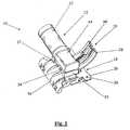
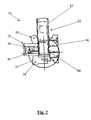
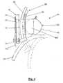
Fig. 1 is a perspective view of an active bolster mechanism according to an embodiment of the present invention.Fig. 2 is a side view of an active bolster mechanism according to an embodiment of the present invention having an actuator positioned in a first orientation.Fig. 3 is a side view of the active bolster mechanism ofFig. 2 showing the actuator in a second orientation.Fig. 4 is a schematic view of an active bolster system according to an embodiment of the present invention illustrating a portion of its range of motion as viewed from above.- In the following detailed description numerous specific details are set forth in order to provide a thorough understanding of the invention. However, it will be understood by those skilled in the art that the present invention may be practiced without these specific details. For example, the invention is not limited in scope to the particular type of industry application depicted in the figures. In other instances, well-known methods, procedures, and components have not been described in detail so as not to obscure the present invention.
- An active bolster system for a vehicle seat is illustrated in
Figs. 1-4 . Theactive bolster system 10 is associated with a seat bolster. A seat bolster may have aseparate unit 14 as depicted infigure 4 or anintegral pressure surface 36 on anadjustable bolster slider 20 as depicted inFigures 1-3 . Abolster adjusting mechanism 16 varies the position of theseat bolster 14, thereby changing the lateral support provided to an occupant of the seat. Thebolster adjusting mechanism 16 includes amounting plate 18, anadjustable bolster slider 20, and adrive unit 22. In this embodiment, theseat bolster 14 is interposed between the seat occupant and thebolster adjustment mechanism 16. In an alternate embodiment, thebolster adjustment mechanism 16, and, in particular, the pressure surface 36 (described below), acts directly on the occupant with no interposing bolster cushion. The active bolster system described herein is suitable for operation in either of these embodiments. - The
mounting plate 18 is fixed to aseat frame 12. Themounting plate 18 is provided with aguide section 24 and aframe mounting section 26. In the embodiments shown inFigs. 1-4 , theframe mounting section 26 is provided withplural mounting holes 28 through which bolts, rivets, screws or other similar devices are inserted in order to secure themounting plate 18 to theseat frame 12. Other mounting means, for example welding or adhesive, may also be utilized to secure the mounting plate. Theguide section 24 serves the dual purpose of guiding the movement of theadjustable bolster slider 20, as will be explained in detail below, and providing a mounting surface for thedrive unit 22. Theguide section 24 is formed by a pair ofparallel walls frame mounting section 26 and atop surface 34 which extends between thewalls frame mounting section 26. In the embodiment shown, thetop surface 34 is provided with an access hole (not shown) that allows thedrive unit 22 to communicate with theadjustable bolster slider 20. The access hole may be of any suitable shape and size to accommodate the gearing associated with thedrive unit 22. - The
adjustable bolster slider 20 includes apressure surface 36 and anadjustment arm 38. Theseat bolster 14 is connected to thepressure surface 36. Theadjustment arm 38 is provided with a narrower, more elongated configuration than the pressure surface and is designed to interact with theguide section 24 of themounting plate 18. During assembly of the adjustment mechanism, theadjustment arm 38, with width w, is inserted into the space defined by thewalls frame mounting section 26 and thetop surface 34 of the mountingplate 18. During operation of the mechanism, this space partly defines the path that theadjustment arm 38, of theslider 20, travels through. Theadjustment arm 38 includes a strip ofgear teeth 40, which engage gear teeth (not shown) in thedrive unit 22. In the depicted embodiment, theadjustment arm 38 has an angular or arcuate shape. - The
drive unit 22 includes anactuator 42 and a gear set 44. In the embodiment shown theactuator 42 is an electric motor. In a preferred arrangement, theactuator 42 is directly connected to the gear set 44. The gear set 44 in thedrive unit 22 meshes with the strip ofgear teeth 40 on theadjustment arm 38. The gear set includes a series of gears (not shown) arranged to transfer the motive force of theactuator 42 to theadjustment arm 38. - Gear sets of this type are well-known in the art, and, therefore, the following embodiments are not shown in detail in the accompanying drawings. In one embodiment, the
actuator 42 includes an output shaft extending from the actuator towards the gear set 44. A first bevel gear is affixed to the end of the output shaft and is turned with the output shaft by the actuator. A second bevel gear is oriented at a ninety degree angle to and engages with the first bevel gear. The second bevel gear is rotatably mounted on a post that is secured to the housing of the gear set 44. The second bevel gear extends downward from the gear set 44 to engage thegear teeth 40 of theadjustment arm 38. The second bevel gear may be comprised of two separate but connected gears, one engaging with the first bevel gear and the second engaging thegear teeth 40 of the adjustment arm. In alternate embodiments, gear sets utilizing three or more gears are provided to transfer the rotation of theactuator 42 to theadjustment arm 38. The gear ratios of these alternate gear sets may be varied to control the movement of theadjustment arm 38. Alternate gearing arrangements are well-known in the art and may be substituted for the described embodiments. - The
drive unit 22 is also provided with a mounting surface (not shown) to allow thedrive unit 22 to be fixed to thetop surface 34 of theguide section 24. The mounting surface of thedrive unit 22 and thetop surface 34 of the mountingplate 18 are provided with a means for pivotably mounting thedrive unit 22 to the top surface of the mountingplate 18. The means for pivotably mounting thedrive unit 22 allow the actuator to be rotated relative to the mountingplate 18, thereby providing a variety of mounting positions for the bolster adjustment mechanism relative to the seat frame and increasing the flexibility of the active bolster system. In one embodiment, the means for pivotally mounting thedrive unit 22 is formed by a plurality of mounting holes (not shown) located in thetop surface 34 of the mountingplate 18. In another embodiment, the means for pivotally mounting thedrive unit 22 includes a mounting pin (not shown) that is rotatably connected with thedrive unit 22 and thetop surface 34 of the mountingplate 18. The mounting pin is preferably connected with a generally central point of the gear set 44 of the drive unit and a generally central point of thetop surface 34 of the mountingplate 18. Other suitable pivoting mounting arrangements are well-known in the art and, therefore, are not described in detail here. - The direct drive system described above eliminates the use of Bowden cables to control the seat bolsters and results in a more compact bolster adjustment package. In addition, this arrangement provides a modular design that enables the left and right bolster adjustment mechanisms to be removed and replaced independently of one another. Furthermore, the adjustable mounting feature of the drive unit allows a single design to serve both the right and left sides of the seat.
- As the
actuator 42 rotates, it drives the gear set 44. The gear set 44, in turn, drives the strip ofgear teeth 40, and with it theslider 20, in a lateral direction. The amount and direction of rotation of theactuator 42 and gear set 44 determines the amount and direction of travel of theslider 20. In the preferred embodiment with an angular-shapedadjustment arm 38, the resulting motion of thepressure surface 36 is an arc. - The active bolster system is particularly well-suited for operation with a dynamic bolster adjustment system. In such a system, the active bolster system operates in conjunction with a control unit and multiple vehicle performance sensors. The control unit may be a microcomputer, a programmable controller, or any other suitable programmable unit known in the art. The control unit communicates with and controls the drive units of the left and right bolster assemblies independently. In a one embodiment, the vehicle performance sensors include an acceleration sensor, a velocity sensor, and a steering angle sensor. Each of these sensors continuously communicates a signal that reflects the current acceleration, velocity or steering angle to the control unit during vehicle operation. From these signals, the control unit calculates the approximate current lateral forces being exerted on the vehicle occupants. Based on the amount and direction of the current lateral forces being exerted, the control unit determines the proper positioning for each of the left and right bolsters. The control unit then signals the amount and direction of rotation of each actuator required to achieve those positions. The control unit then transmits separate signals to the drive units of the left and right bolster assemblies directing the actuator of the each drive unit to rotate the desired amount in the proper direction. This results in the left and right seat bolsters being properly positioned to provide optimal lateral support for the seat occupant based on the current lateral forces being exerted on the occupant.
Claims (17)
- A lateral bolster adjustment apparatus for a seat, comprising:a mounting plate (18) having a seat frame mounting section (26) and a guide section (24);a drive unit (22) comprising an actuator (42); andan adjustable lateral bolster slider (20) in sliding communication with the guide section of said mounting plate,characterized in thatsaid slider (20) has an integral lateral bolster pressure surface (36), an integral adjustment arm (38), and an integral gear tooth strip (40) associated with said adjustment arm, all being formed of a single piece of material; andwherein the drive unit (22) further comprises a gear set (44), wherein the gear set communicates directly with the integral gear tooth strip of said lateral bolster slider.
- The lateral bolster adjustment apparatus of claim 1, furthercharacterized in that the drive unit (22) is pivotably mounted on said mounting plate (18).
- The lateral bolster adjustment apparatus of claim 1, furthercharacterized in that said gear set (44) is pivotably mounted to said mounting plate (18).
- The lateral bolster adjustment apparatus as set forth in any of the preceding claims, furthercharacterized in that the actuator (42) communicates directly with said gear set (44).
- A lateral bolster adjustment apparatus as set forth in any of the preceding claims, furthercharacterized in that said actuator (42) is an electric motor.
- A lateral bolster adjustment apparatus as set forth in any of the preceding claims, furthercharacterized in that said integral adjustment arm (38) and integral gear tooth strip (40) are arcuate in shape such that the lateral bolster pressure surface (36) applies pressure at significantly different angles with respect to the mounting plate (18) as the adjustable lateral bolster slider (20) is slideably engaged by the gear set (44).
- A lateral bolster adjustment apparatus as set forth in any of the preceding claims, furthercharacterized in that said integral adjustment arm (38) and integral gear tooth strip (40) slide into said guide section (24) and said guide section (24) guides the slidable movement of the adjustable lateral bolster slider (20).
- A lateral bolster adjustment apparatus as set forth in any of the preceding claims, furthercharacterized in that said guide section (24) includes a top surface (34) and said drive unit (22) is mounted directly to the top surface (34) of said guide section (24).
- A lateral bolster adjustment apparatus as set forth in claim 8, furthercharacterized in that said top surface (34) of said guide section (24) includes a plurality of mounting holes (28) positioned such that said drive unit (22) is mountable to said guide section (24) in a plurality of orientations.
- A lateral bolster adjustment apparatus as set forth in any of the preceding claims, furthercharacterized in that said gear set (44) is positioned directly above the integral gear tooth strip (40).
- A lateral bolster adjustment apparatus as set forth in any of the preceding claims, furthercharacterized in that said drive unit (22) is pivotably mounted to said top surface (34) of said guide section (24).
- A lateral bolster adjustment apparatus as set forth in claim 11, furthercharacterized in that the pivotable mounting of the drive unit is by a mounting pin rotatably connecting said drive unit (22) with the top surface (34) of said guide section (24).
- A lateral bolster adjustment apparatus as set forth in claim 12, furthercharacterized in that the mounting pin is in a generally central position relative to said top surface (34) of said guide section (24).
- A lateral bolster adjustment apparatus as set forth in any of claims 11, 12 or 13, furthercharacterized in that said pivoting drive unit (22) is in direct communication with said adjustable lateral bolster slider (20).
- A lateral bolster adjustment apparatus as set forth in any of the preceding claims, furthercharacterized in that the outer dimensions of the gear set (44) are substantially within a perimeter of said mounting plate (18).
- A lateral bolster adjustment apparatus as set forth in any of the preceding claims, furthercharacterized in that the outer dimensions of the adjustable lateral bolster slider (20) are substantially within a perimeter of said mounting plate (18) in at least one dimension.
- A lateral bolster adjustment apparatus as set forth in any of claims 1 through 16, furthercharacterized in that said mounting plate (18) includes an integral lateral seat frame mounting section (26), a guide section (24), and a top surface (34) associated with said guide section (24) for direct mounting of said gear set (44).
Applications Claiming Priority (3)
| Application Number | Priority Date | Filing Date | Title |
|---|---|---|---|
| US10/280,446US7125077B2 (en) | 2002-10-25 | 2002-10-25 | Seat bolster adjustment apparatus and method |
| US280446 | 2002-10-25 | ||
| PCT/US2003/033893WO2004037045A1 (en) | 2002-10-25 | 2003-10-24 | Seat bolster system apparatus and method |
Publications (3)
| Publication Number | Publication Date |
|---|---|
| EP1558114A1 EP1558114A1 (en) | 2005-08-03 |
| EP1558114A4 EP1558114A4 (en) | 2010-04-28 |
| EP1558114B1true EP1558114B1 (en) | 2014-11-26 |
Family
ID=32106940
Family Applications (1)
| Application Number | Title | Priority Date | Filing Date |
|---|---|---|---|
| EP03776543.5AExpired - LifetimeEP1558114B1 (en) | 2002-10-25 | 2003-10-24 | Seat bolster system apparatus and method |
Country Status (8)
| Country | Link |
|---|---|
| US (1) | US7125077B2 (en) |
| EP (1) | EP1558114B1 (en) |
| JP (1) | JP4083106B2 (en) |
| KR (1) | KR100687021B1 (en) |
| CN (1) | CN100439147C (en) |
| AU (1) | AU2003284154A1 (en) |
| DE (1) | DE10349289A1 (en) |
| WO (1) | WO2004037045A1 (en) |
Families Citing this family (60)
| Publication number | Priority date | Publication date | Assignee | Title |
|---|---|---|---|---|
| DE202004013668U1 (en)* | 2004-08-30 | 2006-01-05 | Brose Fahrzeugteile Gmbh & Co. Kommanditgesellschaft, Coburg | Motor vehicle seat with adjustable side bolsters |
| EP1871198B1 (en)* | 2005-04-08 | 2009-08-26 | Schukra Gerätebau AG | Device and method for regulating a lateral part of a seat |
| US7232174B1 (en)* | 2005-04-11 | 2007-06-19 | Trott Gregory L A | Adjustable vehicle seat for providing lateral torso support |
| KR20090031413A (en)* | 2006-07-11 | 2009-03-25 | 인티어 오토모티브, 인크. | Adjustable bolster assembly |
| JP5125192B2 (en)* | 2007-04-10 | 2013-01-23 | トヨタ紡織株式会社 | Vehicle seat |
| US20090045662A1 (en)* | 2007-08-14 | 2009-02-19 | Schukra Of North America, Ltd. | Head Rest for Seat |
| US8246057B2 (en) | 2008-11-27 | 2012-08-21 | Bombardier Recreational Products Inc. | Side supports for straddle-type seat |
| DE202009000559U1 (en)* | 2009-01-09 | 2010-05-27 | Brose Fahrzeugteile Gmbh & Co. Kommanditgesellschaft, Coburg | Device for adjusting the hardness and geometry of seat elements of a motor vehicle seat |
| US8454090B2 (en)* | 2009-09-14 | 2013-06-04 | Leggett & Platt Canada Co. | Pelvic and lumbar support system |
| US9717340B2 (en) | 2010-09-13 | 2017-08-01 | Tropitone Furniture Co., Inc. | Adjustable seating and furniture |
| US8534758B2 (en) | 2010-09-13 | 2013-09-17 | Tropitone Furniture Co., Inc. | Reclinable seating apparatus and method |
| US8740303B2 (en)* | 2012-06-22 | 2014-06-03 | Michael V. Halliday | Customizable chair with multipoint adjustment |
| US9254042B2 (en) | 2012-06-22 | 2016-02-09 | Michael V. Halliday | Backrest member including an adjustable platform for use with a chair |
| US9409504B2 (en) | 2013-01-24 | 2016-08-09 | Ford Global Technologies, Llc | Flexible seatback system |
| US9399418B2 (en) | 2013-01-24 | 2016-07-26 | Ford Global Technologies, Llc | Independent cushion extension and thigh support |
| US9415713B2 (en) | 2013-01-24 | 2016-08-16 | Ford Global Technologies, Llc | Flexible seatback system |
| US9193284B2 (en) | 2013-06-11 | 2015-11-24 | Ford Global Technologies, Llc | Articulating cushion bolster for ingress/egress |
| US9045063B2 (en) | 2013-06-11 | 2015-06-02 | Ford Global Technologies, Llc | Articulating seat bolsters |
| KR101440149B1 (en) | 2013-10-17 | 2014-09-15 | 현대다이모스(주) | Apparatus for seat side bolster of vehicle |
| KR101470223B1 (en)* | 2013-10-22 | 2014-12-08 | 현대다이모스(주) | Apparatus for seat side bolster of vehicle |
| US9315131B2 (en) | 2014-01-23 | 2016-04-19 | Ford Global Technologies, Llc | Suspension seat back and cushion system having an inner suspension panel |
| US9421894B2 (en) | 2014-04-02 | 2016-08-23 | Ford Global Technologies, Llc | Vehicle seating assembly with manual independent thigh supports |
| US9789790B2 (en) | 2014-10-03 | 2017-10-17 | Ford Global Technologies, Llc | Tuned flexible support member and flexible suspension features for comfort carriers |
| US9505324B2 (en)* | 2015-01-27 | 2016-11-29 | Leggett & Platt Canada Co. | Adjustable bolster |
| US10046682B2 (en) | 2015-08-03 | 2018-08-14 | Ford Global Technologies, Llc | Back cushion module for a vehicle seating assembly |
| US9849817B2 (en) | 2016-03-16 | 2017-12-26 | Ford Global Technologies, Llc | Composite seat structure |
| US10286818B2 (en) | 2016-03-16 | 2019-05-14 | Ford Global Technologies, Llc | Dual suspension seating assembly |
| US10562412B1 (en) | 2016-03-24 | 2020-02-18 | Xsensor Technology Corporation | Intelligent seat systems |
| US9994135B2 (en) | 2016-03-30 | 2018-06-12 | Ford Global Technologies, Llc | Independent cushion thigh support |
| US10220737B2 (en) | 2016-04-01 | 2019-03-05 | Ford Global Technologies, Llc | Kinematic back panel |
| US9889773B2 (en) | 2016-04-04 | 2018-02-13 | Ford Global Technologies, Llc | Anthropomorphic upper seatback |
| US9802512B1 (en) | 2016-04-12 | 2017-10-31 | Ford Global Technologies, Llc | Torsion spring bushing |
| US9845029B1 (en) | 2016-06-06 | 2017-12-19 | Ford Global Technologies, Llc | Passive conformal seat with hybrid air/liquid cells |
| US9834166B1 (en) | 2016-06-07 | 2017-12-05 | Ford Global Technologies, Llc | Side airbag energy management system |
| US9849856B1 (en) | 2016-06-07 | 2017-12-26 | Ford Global Technologies, Llc | Side airbag energy management system |
| US10166895B2 (en) | 2016-06-09 | 2019-01-01 | Ford Global Technologies, Llc | Seatback comfort carrier |
| US10377279B2 (en) | 2016-06-09 | 2019-08-13 | Ford Global Technologies, Llc | Integrated decking arm support feature |
| US10286824B2 (en) | 2016-08-24 | 2019-05-14 | Ford Global Technologies, Llc | Spreader plate load distribution |
| US10279714B2 (en) | 2016-08-26 | 2019-05-07 | Ford Global Technologies, Llc | Seating assembly with climate control features |
| US10239431B2 (en) | 2016-09-02 | 2019-03-26 | Ford Global Technologies, Llc | Cross-tube attachment hook features for modular assembly and support |
| US10391910B2 (en) | 2016-09-02 | 2019-08-27 | Ford Global Technologies, Llc | Modular assembly cross-tube attachment tab designs and functions |
| US10286825B2 (en) | 2016-09-08 | 2019-05-14 | Ford Global Technologies, Llc | Support assembly for a vehicle seat |
| US9914378B1 (en) | 2016-12-16 | 2018-03-13 | Ford Global Technologies, Llc | Decorative and functional upper seatback closeout assembly |
| US10596936B2 (en) | 2017-05-04 | 2020-03-24 | Ford Global Technologies, Llc | Self-retaining elastic strap for vent blower attachment to a back carrier |
| US10464455B2 (en) | 2017-07-28 | 2019-11-05 | Ford Global Technologies, Llc | Active seat bolster adjustment based on occupant pressure map and method |
| US11192469B2 (en) | 2019-01-30 | 2021-12-07 | Toyota Motor Engineering & Manufacturing North America, Inc. | Vehicle seat with morphing bolsters |
| US11285844B2 (en) | 2019-01-31 | 2022-03-29 | Toyota Motor Engineering & Manufacturing North America, Inc. | Vehicle seat with morphing portions |
| US10960793B2 (en) | 2019-03-06 | 2021-03-30 | Toyota Motor Engineering & Manufacturing North America, Inc. | Active vehicle seat with morphing portions |
| US11370330B2 (en) | 2019-03-22 | 2022-06-28 | Toyota Motor Engineering & Manufacturing North America, Inc. | Vehicle seat with morphing portions |
| US11752901B2 (en) | 2019-03-28 | 2023-09-12 | Toyota Motor Engineering & Manufacturing North America, Inc. | Vehicle seat with tilting seat portion |
| KR102205602B1 (en) | 2019-04-12 | 2021-01-21 | (주)화소 | Positioning Pin for Serration Bar Jointed Seat Motor of Car |
| US11897379B2 (en) | 2021-10-20 | 2024-02-13 | Toyota Motor Engineering & Manufacturing North America, Inc. | Seat with shape memory material member actuation |
| US12383066B2 (en) | 2022-04-26 | 2025-08-12 | Toyota Motor Engineering & Manufacturing North America, Inc. | Chair with shape memory material-based movement synchronized with visual content |
| US11932142B2 (en) | 2022-08-18 | 2024-03-19 | Ford Global Technologies, Llc | Additive manufactured cushioned component |
| US11780355B1 (en) | 2022-08-18 | 2023-10-10 | Ford Global Technologies, Llc | Additive manufactured cushioned component |
| US12241458B2 (en) | 2023-02-16 | 2025-03-04 | Toyota Motor Engineering & Manufacturing North America, Inc. | Actuator with contracting member |
| US12270386B2 (en) | 2023-02-16 | 2025-04-08 | Toyota Motor Engineering & Manufacturing North America, Inc. | Shape memory material member-based actuator |
| US12163507B2 (en) | 2023-02-22 | 2024-12-10 | Toyota Motor Engineering & Manufacturing North America, Inc. | Contracting member-based actuator with clutch |
| US12152570B2 (en) | 2023-02-22 | 2024-11-26 | Toyota Motor Engineering & Manufacturing North America, Inc. | Shape memory material member-based actuator with electrostatic clutch preliminary class |
| US12234811B1 (en) | 2023-08-21 | 2025-02-25 | Toyota Motor Engineering & Manufacturing North America, Inc. | Monitoring a state of a shape memory material member |
Citations (2)
| Publication number | Priority date | Publication date | Assignee | Title |
|---|---|---|---|---|
| US4500136A (en)* | 1980-07-30 | 1985-02-19 | Lear Siegler, Inc. | Vehicle seat including improved adjustable side bolsters |
| WO2002001988A2 (en)* | 2000-06-30 | 2002-01-10 | L & P Property Management Company | Lumbar support device |
Family Cites Families (26)
| Publication number | Priority date | Publication date | Assignee | Title |
|---|---|---|---|---|
| FR2097577A5 (en) | 1970-07-10 | 1972-03-03 | Peugeot & Renault | |
| US4244623A (en)* | 1979-05-08 | 1981-01-13 | Uop Inc. | Multi-position armrest |
| MX154470A (en)* | 1981-12-23 | 1987-08-28 | Keiper Recaro Gmbh Co | CAR SEAT IMPROVEMENTS |
| DE3624396A1 (en) | 1986-07-18 | 1988-01-28 | Hammerstein Gmbh C Rob | Vehicle seat with an adjustable lordosis support, arranged in the backrest |
| IT1203852B (en)* | 1987-04-03 | 1989-02-23 | Claudio Zarotti | STRUCTURE OF ARMCHAIR, SOFA AND SIMILAR |
| JPH0667702B2 (en)* | 1988-03-23 | 1994-08-31 | 株式会社豊田自動織機製作所 | Seat with automatic side support |
| JP2719605B2 (en)* | 1988-07-19 | 1998-02-25 | アイシン精機株式会社 | Reclining adjuster |
| IT1223725B (en)* | 1988-07-25 | 1990-09-29 | Sicam Linea Srl | VEHICLE SEAT |
| JPH0321247U (en)* | 1989-07-13 | 1991-03-01 | ||
| JPH0644461U (en)* | 1992-11-25 | 1994-06-14 | 車体工業株式会社 | Seat for automatically restraining the occupant's center of gravity while the vehicle is turning |
| JPH08205955A (en)* | 1995-02-08 | 1996-08-13 | Aisin Seiki Co Ltd | Lumber support device |
| KR0131029B1 (en)* | 1995-04-06 | 1998-04-21 | 전성원 | Easy to adjust car headrest |
| US5662382A (en)* | 1996-07-15 | 1997-09-02 | Lear Corporation | Vehicle seat with integral child restraint seat and interlocking headrest assembly |
| US5803544A (en)* | 1996-08-16 | 1998-09-08 | H. O. Bostrom Company, Inc. | Seat construction with removable side cushions |
| US5829839A (en)* | 1996-10-17 | 1998-11-03 | Haworth, Inc. | Height-adjustable chair arm assembly having gear-type adjusting mechanism |
| US5857743A (en) | 1997-02-10 | 1999-01-12 | Mccord Winn Textron Inc. | Power adjustable side bolster |
| CA2201253C (en)* | 1997-03-27 | 2001-08-28 | William R. Breen | Chair control |
| US5795026A (en)* | 1997-06-06 | 1998-08-18 | Haworth, Inc. | Height adjustable chair arm |
| DE19756700C1 (en)* | 1997-12-19 | 1998-12-17 | Daimler Benz Ag | Adjustable vehicle seat |
| US5884975A (en)* | 1998-02-26 | 1999-03-23 | Su; Wen-Fa | Chair armrest |
| DE19915003A1 (en) | 1999-04-01 | 2000-10-05 | Michael Stips | Chair for work machines or training devices, or for use as vehicle seat; has movable seat underlay connected to support unit, and having support structure and movable seat part |
| DE19958677C1 (en)* | 1999-12-06 | 2001-05-03 | Faure Bertrand Sitztech Gmbh | Vehicle seat has center springs where the hardness can be adjusted together with the setting of the height of the upper edges of the seat side beads |
| US6802563B1 (en)* | 2000-03-06 | 2004-10-12 | Lear Corporation | Adjustable seat bolsters |
| DE10012973B4 (en)* | 2000-03-16 | 2004-02-26 | Daimlerchrysler Ag | Headrest for a vehicle seat |
| US6460932B1 (en)* | 2000-06-09 | 2002-10-08 | Krueger International, Inc. | Arm height adjustment mechanism for a chair |
| KR100408900B1 (en)* | 2001-06-20 | 2003-12-11 | 이종호 | Armrest device for computer working |
- 2002
- 2002-10-25USUS10/280,446patent/US7125077B2/ennot_activeExpired - Lifetime
- 2003
- 2003-10-23DEDE10349289Apatent/DE10349289A1/ennot_activeWithdrawn
- 2003-10-24AUAU2003284154Apatent/AU2003284154A1/ennot_activeAbandoned
- 2003-10-24CNCNB2003101043561Apatent/CN100439147C/ennot_activeExpired - Fee Related
- 2003-10-24EPEP03776543.5Apatent/EP1558114B1/ennot_activeExpired - Lifetime
- 2003-10-24KRKR1020057007102Apatent/KR100687021B1/ennot_activeExpired - Fee Related
- 2003-10-24WOPCT/US2003/033893patent/WO2004037045A1/ennot_activeApplication Discontinuation
- 2003-10-27JPJP2003365767Apatent/JP4083106B2/ennot_activeExpired - Fee Related
Patent Citations (2)
| Publication number | Priority date | Publication date | Assignee | Title |
|---|---|---|---|---|
| US4500136A (en)* | 1980-07-30 | 1985-02-19 | Lear Siegler, Inc. | Vehicle seat including improved adjustable side bolsters |
| WO2002001988A2 (en)* | 2000-06-30 | 2002-01-10 | L & P Property Management Company | Lumbar support device |
Also Published As
| Publication number | Publication date |
|---|---|
| EP1558114A1 (en) | 2005-08-03 |
| CN100439147C (en) | 2008-12-03 |
| CN1500670A (en) | 2004-06-02 |
| JP2004141664A (en) | 2004-05-20 |
| KR100687021B1 (en) | 2007-02-26 |
| KR20060011935A (en) | 2006-02-06 |
| US20040080198A1 (en) | 2004-04-29 |
| JP4083106B2 (en) | 2008-04-30 |
| DE10349289A1 (en) | 2004-05-13 |
| WO2004037045A1 (en) | 2004-05-06 |
| EP1558114A4 (en) | 2010-04-28 |
| AU2003284154A1 (en) | 2004-05-13 |
| US7125077B2 (en) | 2006-10-24 |
Similar Documents
| Publication | Publication Date | Title |
|---|---|---|
| EP1558114B1 (en) | Seat bolster system apparatus and method | |
| JP3593131B2 (en) | Adjustable waist support | |
| JP4620665B2 (en) | Car seat back structure for car seat | |
| JP4922166B2 (en) | Automotive seat with adjustable side cheeks | |
| US7131695B2 (en) | Vehicle seat section adjusting device | |
| EP1726476A2 (en) | Vehicle seat and method of supporting driver/passenger using the same | |
| GB2277021A (en) | A height adjustable automotive vehicle seat | |
| US20120025582A1 (en) | Seat assembly having an adjustable head restraint assembly | |
| IE914430A1 (en) | Mechanism supporting a thigh-rest cushion | |
| KR101470213B1 (en) | Apparatus for seat side bolster of vehicle | |
| GB2081086A (en) | Vehicle seat including adjustable side bolsters | |
| EP1571064B1 (en) | Adjustable pedal and steering mechanism | |
| KR101470223B1 (en) | Apparatus for seat side bolster of vehicle | |
| JPH0537860Y2 (en) | ||
| EP4311747A1 (en) | Vehicle with movable driver's station | |
| US20020023516A1 (en) | Adjustable foot-operated control mechanism | |
| EP1217492B1 (en) | Adjustable pedal for motor-vehicles | |
| EP1382480B1 (en) | Control system for a vehicle seat | |
| KR101956985B1 (en) | Tilting apparatus of front seat for vehicle | |
| KR100196175B1 (en) | Car seat | |
| KR100187146B1 (en) | Lumbar supportable apparatus for automobile seat | |
| KR0153655B1 (en) | Bolster control device of seat for a car | |
| KR0120863Y1 (en) | Front seat width adjustment | |
| KR100287330B1 (en) | Automotive power seat transmission | |
| KR20020055679A (en) | Repositioning device of seat cushion spring for automobile |
Legal Events
| Date | Code | Title | Description |
|---|---|---|---|
| PUAI | Public reference made under article 153(3) epc to a published international application that has entered the european phase | Free format text:ORIGINAL CODE: 0009012 | |
| 17P | Request for examination filed | Effective date:20050519 | |
| AK | Designated contracting states | Kind code of ref document:A1 Designated state(s):AT BE BG CH CY CZ DE DK EE ES FI FR GB GR HU IE IT LI LU MC NL PT RO SE SI SK TR | |
| AX | Request for extension of the european patent | Extension state:AL LT LV MK | |
| DAX | Request for extension of the european patent (deleted) | ||
| A4 | Supplementary search report drawn up and despatched | Effective date:20100325 | |
| 17Q | First examination report despatched | Effective date:20101007 | |
| GRAP | Despatch of communication of intention to grant a patent | Free format text:ORIGINAL CODE: EPIDOSNIGR1 | |
| INTG | Intention to grant announced | Effective date:20140521 | |
| GRAS | Grant fee paid | Free format text:ORIGINAL CODE: EPIDOSNIGR3 | |
| GRAA | (expected) grant | Free format text:ORIGINAL CODE: 0009210 | |
| AK | Designated contracting states | Kind code of ref document:B1 Designated state(s):AT BE BG CH CY CZ DE DK EE ES FI FR GB GR HU IE IT LI LU MC NL PT RO SE SI SK TR | |
| REG | Reference to a national code | Ref country code:GB Ref legal event code:FG4D | |
| REG | Reference to a national code | Ref country code:CH Ref legal event code:EP | |
| REG | Reference to a national code | Ref country code:AT Ref legal event code:REF Ref document number:697683 Country of ref document:AT Kind code of ref document:T Effective date:20141215 | |
| REG | Reference to a national code | Ref country code:IE Ref legal event code:FG4D | |
| REG | Reference to a national code | Ref country code:DE Ref legal event code:R096 Ref document number:60347041 Country of ref document:DE Effective date:20141231 | |
| REG | Reference to a national code | Ref country code:NL Ref legal event code:VDEP Effective date:20141126 | |
| REG | Reference to a national code | Ref country code:AT Ref legal event code:MK05 Ref document number:697683 Country of ref document:AT Kind code of ref document:T Effective date:20141126 | |
| PG25 | Lapsed in a contracting state [announced via postgrant information from national office to epo] | Ref country code:FI Free format text:LAPSE BECAUSE OF FAILURE TO SUBMIT A TRANSLATION OF THE DESCRIPTION OR TO PAY THE FEE WITHIN THE PRESCRIBED TIME-LIMIT Effective date:20141126 Ref country code:ES Free format text:LAPSE BECAUSE OF FAILURE TO SUBMIT A TRANSLATION OF THE DESCRIPTION OR TO PAY THE FEE WITHIN THE PRESCRIBED TIME-LIMIT Effective date:20141126 Ref country code:NL Free format text:LAPSE BECAUSE OF FAILURE TO SUBMIT A TRANSLATION OF THE DESCRIPTION OR TO PAY THE FEE WITHIN THE PRESCRIBED TIME-LIMIT Effective date:20141126 Ref country code:PT Free format text:LAPSE BECAUSE OF FAILURE TO SUBMIT A TRANSLATION OF THE DESCRIPTION OR TO PAY THE FEE WITHIN THE PRESCRIBED TIME-LIMIT Effective date:20150326 | |
| PG25 | Lapsed in a contracting state [announced via postgrant information from national office to epo] | Ref country code:AT Free format text:LAPSE BECAUSE OF FAILURE TO SUBMIT A TRANSLATION OF THE DESCRIPTION OR TO PAY THE FEE WITHIN THE PRESCRIBED TIME-LIMIT Effective date:20141126 Ref country code:GR Free format text:LAPSE BECAUSE OF FAILURE TO SUBMIT A TRANSLATION OF THE DESCRIPTION OR TO PAY THE FEE WITHIN THE PRESCRIBED TIME-LIMIT Effective date:20150227 Ref country code:CY Free format text:LAPSE BECAUSE OF FAILURE TO SUBMIT A TRANSLATION OF THE DESCRIPTION OR TO PAY THE FEE WITHIN THE PRESCRIBED TIME-LIMIT Effective date:20141126 Ref country code:SE Free format text:LAPSE BECAUSE OF FAILURE TO SUBMIT A TRANSLATION OF THE DESCRIPTION OR TO PAY THE FEE WITHIN THE PRESCRIBED TIME-LIMIT Effective date:20141126 | |
| PG25 | Lapsed in a contracting state [announced via postgrant information from national office to epo] | Ref country code:CZ Free format text:LAPSE BECAUSE OF FAILURE TO SUBMIT A TRANSLATION OF THE DESCRIPTION OR TO PAY THE FEE WITHIN THE PRESCRIBED TIME-LIMIT Effective date:20141126 Ref country code:EE Free format text:LAPSE BECAUSE OF FAILURE TO SUBMIT A TRANSLATION OF THE DESCRIPTION OR TO PAY THE FEE WITHIN THE PRESCRIBED TIME-LIMIT Effective date:20141126 Ref country code:RO Free format text:LAPSE BECAUSE OF FAILURE TO SUBMIT A TRANSLATION OF THE DESCRIPTION OR TO PAY THE FEE WITHIN THE PRESCRIBED TIME-LIMIT Effective date:20141126 Ref country code:DK Free format text:LAPSE BECAUSE OF FAILURE TO SUBMIT A TRANSLATION OF THE DESCRIPTION OR TO PAY THE FEE WITHIN THE PRESCRIBED TIME-LIMIT Effective date:20141126 Ref country code:SK Free format text:LAPSE BECAUSE OF FAILURE TO SUBMIT A TRANSLATION OF THE DESCRIPTION OR TO PAY THE FEE WITHIN THE PRESCRIBED TIME-LIMIT Effective date:20141126 | |
| REG | Reference to a national code | Ref country code:DE Ref legal event code:R097 Ref document number:60347041 Country of ref document:DE | |
| PLBE | No opposition filed within time limit | Free format text:ORIGINAL CODE: 0009261 | |
| STAA | Information on the status of an ep patent application or granted ep patent | Free format text:STATUS: NO OPPOSITION FILED WITHIN TIME LIMIT | |
| 26N | No opposition filed | Effective date:20150827 | |
| PG25 | Lapsed in a contracting state [announced via postgrant information from national office to epo] | Ref country code:IT Free format text:LAPSE BECAUSE OF FAILURE TO SUBMIT A TRANSLATION OF THE DESCRIPTION OR TO PAY THE FEE WITHIN THE PRESCRIBED TIME-LIMIT Effective date:20141126 | |
| PG25 | Lapsed in a contracting state [announced via postgrant information from national office to epo] | Ref country code:SI Free format text:LAPSE BECAUSE OF FAILURE TO SUBMIT A TRANSLATION OF THE DESCRIPTION OR TO PAY THE FEE WITHIN THE PRESCRIBED TIME-LIMIT Effective date:20141126 | |
| PG25 | Lapsed in a contracting state [announced via postgrant information from national office to epo] | Ref country code:LU Free format text:LAPSE BECAUSE OF FAILURE TO SUBMIT A TRANSLATION OF THE DESCRIPTION OR TO PAY THE FEE WITHIN THE PRESCRIBED TIME-LIMIT Effective date:20151024 | |
| REG | Reference to a national code | Ref country code:CH Ref legal event code:PL | |
| GBPC | Gb: european patent ceased through non-payment of renewal fee | Effective date:20151024 | |
| PG25 | Lapsed in a contracting state [announced via postgrant information from national office to epo] | Ref country code:MC Free format text:LAPSE BECAUSE OF FAILURE TO SUBMIT A TRANSLATION OF THE DESCRIPTION OR TO PAY THE FEE WITHIN THE PRESCRIBED TIME-LIMIT Effective date:20141126 | |
| REG | Reference to a national code | Ref country code:IE Ref legal event code:MM4A | |
| PG25 | Lapsed in a contracting state [announced via postgrant information from national office to epo] | Ref country code:GB Free format text:LAPSE BECAUSE OF NON-PAYMENT OF DUE FEES Effective date:20151024 Ref country code:CH Free format text:LAPSE BECAUSE OF NON-PAYMENT OF DUE FEES Effective date:20151031 Ref country code:LI Free format text:LAPSE BECAUSE OF NON-PAYMENT OF DUE FEES Effective date:20151031 | |
| REG | Reference to a national code | Ref country code:FR Ref legal event code:ST Effective date:20160630 | |
| PG25 | Lapsed in a contracting state [announced via postgrant information from national office to epo] | Ref country code:FR Free format text:LAPSE BECAUSE OF NON-PAYMENT OF DUE FEES Effective date:20151102 | |
| PG25 | Lapsed in a contracting state [announced via postgrant information from national office to epo] | Ref country code:IE Free format text:LAPSE BECAUSE OF NON-PAYMENT OF DUE FEES Effective date:20151024 | |
| PG25 | Lapsed in a contracting state [announced via postgrant information from national office to epo] | Ref country code:BG Free format text:LAPSE BECAUSE OF FAILURE TO SUBMIT A TRANSLATION OF THE DESCRIPTION OR TO PAY THE FEE WITHIN THE PRESCRIBED TIME-LIMIT Effective date:20141126 Ref country code:HU Free format text:LAPSE BECAUSE OF FAILURE TO SUBMIT A TRANSLATION OF THE DESCRIPTION OR TO PAY THE FEE WITHIN THE PRESCRIBED TIME-LIMIT; INVALID AB INITIO Effective date:20031024 | |
| PG25 | Lapsed in a contracting state [announced via postgrant information from national office to epo] | Ref country code:TR Free format text:LAPSE BECAUSE OF FAILURE TO SUBMIT A TRANSLATION OF THE DESCRIPTION OR TO PAY THE FEE WITHIN THE PRESCRIBED TIME-LIMIT Effective date:20141126 | |
| PG25 | Lapsed in a contracting state [announced via postgrant information from national office to epo] | Ref country code:BE Free format text:LAPSE BECAUSE OF FAILURE TO SUBMIT A TRANSLATION OF THE DESCRIPTION OR TO PAY THE FEE WITHIN THE PRESCRIBED TIME-LIMIT Effective date:20141126 | |
| PGFP | Annual fee paid to national office [announced via postgrant information from national office to epo] | Ref country code:DE Payment date:20201013 Year of fee payment:18 | |
| REG | Reference to a national code | Ref country code:DE Ref legal event code:R119 Ref document number:60347041 Country of ref document:DE | |
| PG25 | Lapsed in a contracting state [announced via postgrant information from national office to epo] | Ref country code:DE Free format text:LAPSE BECAUSE OF NON-PAYMENT OF DUE FEES Effective date:20220503 | |
| P01 | Opt-out of the competence of the unified patent court (upc) registered | Effective date:20230523 |