EP1557929B1 - Method and apparatus for reducing hot spot temperatures on stacked field windings - Google Patents
Method and apparatus for reducing hot spot temperatures on stacked field windingsDownload PDFInfo
- Publication number
- EP1557929B1 EP1557929B1EP05250185AEP05250185AEP1557929B1EP 1557929 B1EP1557929 B1EP 1557929B1EP 05250185 AEP05250185 AEP 05250185AEP 05250185 AEP05250185 AEP 05250185AEP 1557929 B1EP1557929 B1EP 1557929B1
- Authority
- EP
- European Patent Office
- Prior art keywords
- turn
- turns
- thickness
- rotor
- slot
- Prior art date
- Legal status (The legal status is an assumption and is not a legal conclusion. Google has not performed a legal analysis and makes no representation as to the accuracy of the status listed.)
- Ceased
Links
- 238000004804windingMethods0.000titleclaimsdescription50
- 238000000034methodMethods0.000titleclaimsdescription12
- RYGMFSIKBFXOCR-UHFFFAOYSA-NCopperChemical compound[Cu]RYGMFSIKBFXOCR-UHFFFAOYSA-N0.000claimsdescription36
- 229910052802copperInorganic materials0.000claimsdescription36
- 239000010949copperSubstances0.000claimsdescription36
- 230000020169heat generationEffects0.000claimsdescription12
- 230000002829reductive effectEffects0.000claimsdescription9
- 238000009413insulationMethods0.000claimsdescription7
- 230000004323axial lengthEffects0.000claimsdescription4
- UFHFLCQGNIYNRP-UHFFFAOYSA-NHydrogenChemical compound[H][H]UFHFLCQGNIYNRP-UHFFFAOYSA-N0.000description9
- 239000001257hydrogenSubstances0.000description8
- 229910052739hydrogenInorganic materials0.000description8
- 239000004020conductorSubstances0.000description5
- 230000008901benefitEffects0.000description3
- 238000001816coolingMethods0.000description3
- 230000008569processEffects0.000description3
- 230000009467reductionEffects0.000description3
- 238000009423ventilationMethods0.000description3
- 238000010276constructionMethods0.000description2
- 239000002826coolantSubstances0.000description2
- 230000008878couplingEffects0.000description2
- 238000010168coupling processMethods0.000description2
- 238000005859coupling reactionMethods0.000description2
- 238000010586diagramMethods0.000description2
- 125000006850spacer groupChemical group0.000description2
- 230000000903blocking effectEffects0.000description1
- 230000002860competitive effectEffects0.000description1
- 239000000112cooling gasSubstances0.000description1
- 230000007812deficiencyEffects0.000description1
- 230000006872improvementEffects0.000description1
- 239000012212insulatorSubstances0.000description1
- 230000000670limiting effectEffects0.000description1
- 239000007788liquidSubstances0.000description1
- 230000036961partial effectEffects0.000description1
- 238000005086pumpingMethods0.000description1
- 238000004080punchingMethods0.000description1
- 230000000717retained effectEffects0.000description1
- 238000002076thermal analysis methodMethods0.000description1
- 238000005382thermal cyclingMethods0.000description1
- XLYOFNOQVPJJNP-UHFFFAOYSA-NwaterSubstancesOXLYOFNOQVPJJNP-UHFFFAOYSA-N0.000description1
Images


Classifications
- H—ELECTRICITY
- H02—GENERATION; CONVERSION OR DISTRIBUTION OF ELECTRIC POWER
- H02K—DYNAMO-ELECTRIC MACHINES
- H02K3/00—Details of windings
- H02K3/04—Windings characterised by the conductor shape, form or construction, e.g. with bar conductors
- H02K3/12—Windings characterised by the conductor shape, form or construction, e.g. with bar conductors arranged in slots
- H—ELECTRICITY
- H02—GENERATION; CONVERSION OR DISTRIBUTION OF ELECTRIC POWER
- H02K—DYNAMO-ELECTRIC MACHINES
- H02K9/00—Arrangements for cooling or ventilating
- Y—GENERAL TAGGING OF NEW TECHNOLOGICAL DEVELOPMENTS; GENERAL TAGGING OF CROSS-SECTIONAL TECHNOLOGIES SPANNING OVER SEVERAL SECTIONS OF THE IPC; TECHNICAL SUBJECTS COVERED BY FORMER USPC CROSS-REFERENCE ART COLLECTIONS [XRACs] AND DIGESTS
- Y10—TECHNICAL SUBJECTS COVERED BY FORMER USPC
- Y10T—TECHNICAL SUBJECTS COVERED BY FORMER US CLASSIFICATION
- Y10T29/00—Metal working
- Y10T29/49—Method of mechanical manufacture
- Y10T29/49002—Electrical device making
- Y10T29/4902—Electromagnet, transformer or inductor
- Y10T29/49073—Electromagnet, transformer or inductor by assembling coil and core
Definitions
- This inventionrelates generally to generator field windings and, more specifically, to generator field windings configured and disposed on a generator rotor in a manner to reduce hot spot temperatures.
- Generator rotorsare provided with radial slots about the periphery thereof, for receiving field or rotor windings of coils made up of a number of turns in a radially stacked arrangement, each turn or winding separated by insulation.
- the windingsare retained in the slots by full-length wedges, with creepage blocks interposed between the wedges and the windings.
- Generators currently available from the assignee of the present applicationare placed in three major design classifications based on the cooling medium used: air cooled, hydrogen cooled and liquid cooled. All hydrogen and water cooled generators use direct conductor cooling of the rotor winding for heat removal. Smaller two-pole and all four-pole generators use a radial flow design where hydrogen enters the windings through full length sub-slots and is discharged along the length of the rotor body through radial slots, machined or punched in the copper windings. The hydrogen passes from the conductors through the creepage blocks and wedges to an "air gap" between the rotor and the stator, where it is directed through the stator core to the hydrogen coolers.
- a gap-pickup diagonal-flow cooling processis employed.
- cold hydrogenis scooped up in the air gap between the rotor and stator and driven diagonally inwardly through the rotor field turns to directly remove the heat.
- hydrogen gasis turned and passes diagonally outwardly through the field turns to the air gap in a discharge stator core section.
- the stator core ventilationis coordinated with the rotor cooling gas flow, thus creating an in and out flow of hydrogen through the stator core, through the rotor and returning to the hydrogen cooler through the core.
- the generator field windingsconsist of extruded copper that is drawn at a copper mill and then machined and fabricated into a usable coil. Within the last few years, these coils have been redesigned from square corner fabricated coils, to a "C" coil. The cross section of the copper to make these coils has essentially remained the same. The "C” coil has nevertheless been preferred because many benefits have been derived from that shape relating to cost, cycle time and quality. Nevertheless, in order to maintain a competitive stance in the marketplace, new copper designs are constantly being evaluated for increased performance. With the constant design changes, the cross sectional area of the copper has been increasing. When the thickness increases, radial air cooling ducts that are machined in by a punch operation become increasingly more difficult to produce. For example, conventional punch operations may produce an unacceptable bulge in a width dimension of the copper, and it is therefore necessary to create a ventilation scheme for the increasing cross sections of the copper windings without unacceptable bulges in the width dimension.
- a design requirement that must be met as part of the industry standards on electrical generatorsincludes meeting specific temperature rise requirements within the capability of certain classes of insulation.
- One such design requirementis that the maximum field winding temperature stay below a certain limit.
- the hot spot temperatureis the limiting factor in increasing power density.
- One method of reducing the hotspotincludes increasing the ventilation flow and directing it to regions of high temperature. The disadvantage of increasing flow is that it increases the pumping and windage losses which directly reduce generator efficiency.
- Another methodincludes reducing the amount of heat generation in regions of high temperature. For example, one method of reducing the heat generation includes increasing the cross-section area of the field winding copper thereby reducing the resistance and the local heat generation.
- the assigneepresently makes generator fields with a tapered slot to increase copper content thereby increasing the field thermal capability.
- recent generators that use the tapered slot fieldinclude tapered slots with either square corner field winding designs or c-coil field winding designs.
- the tapered slot designsrequire turns of variable width as a consequence of the slot geometry and may have in the past used thicker turns at the narrow portion of the taper.
- tapered slotsare more costly to machine than parallel slots and turns of variable width in a stack are more complex for manufacturers to make and assemble.
- JP 2002 078265discloses a rotary electric machine with a stator core which has a plurality of winding slots extended along the rotary axis of the rotor and armature windings which are embedded in the winding slots and constituted of a number of multi-layer strand conductors disposed in such a way that at both end parts of the rotor the strand conductor of which the thickness is larger is disposed nearer to the rotor in the radial direction from the rotary center of the rotor.
- JP 54026404discloses conductors with varying thickness.
- a generator coilcomprising: a plurality of stacked windings in a rotor where individual turns are stacked in parallel sided radial slots in the rotor, each successive turn having the same width, said width corresponding to a constant width of the parallel sided radial slots, wherein each turn comprises an axial length of copper having a generally rectangular cross-sectional shape, wherein a first turn has a first thickness and a second turn has a second thickness thicker than said first thickness, said second turn employed in regions of high temperature thereby reducing the temperature thereof in which a two turn thickness is employed in a corresponding parallel sided slot having eleven turns and wherein thicker turns are disposed in regions of higher temperature such that a hot spot temperature corresponding to said region of higher temperature is reduced by about 7 °C from that of using constant turn thickness.
- a method to reduce field winding temperatures for windings in a rotorcomprising; varying turn thickness of individual turns with at least two different thickness turns stacked in a parallel sided slot of the rotor, each successive turn having the same width, said width corresponding to a constant width of the parallel sided radial slots, wherein each turn comprises an axial length of copper having a generally rectangular cross-sectional shape; employing thicker individual turns in a region corresponding to a field hot spot to reduce resistance and local heat generation thereof employing a two turn thickness in a corresponding parallel sided slot having eleven turns and disposing thicker turns are disposed in regions of higher temperature such that a hot spot temperature corresponding to said region of higher temperature is reduced by about 7 °C from that of using constant turn thickness.
- the concept being proposedcapitalizes on the ability to reduce local hot spot temperature by reducing the local heat generation (i.e. by reducing the local resistance of the winding through increasing the copper cross-section area).
- the inventionrelates to an end turn arrangement for windings in a rotor where individual turns are stacked in parallel sided radial slots in the rotor, with successive turns having the same width in a radial inward direction, the end turns of the individual turns of each stack being aligned along both edges defining each slot, wherein the turn thickness is increased in regions of high temperature thereby reducing the temperature.
- An added benefit of having variable turn thicknessis that it results in more uniform field temperatures which results in less thermal cycling, less fatigue, and longer part life as a result of the reduced temperature gradients between the field winding components.
- FIG. 1illustrates a conventional rotor 10 for a generator (or motor).
- the rotorhas a shaft 12 with a power turbine (or mechanical mode) coupling 14 and supported by bearings (not shown).
- the rotor shaft 12also has a collector ring 16 that provides an electrical junction for the rotor field winding.
- the rotorhas a large diameter body 18 that holds the coil windings 20.
- the rotor bodyhas longitudinally oriented slots extending radially outwardly from the center of the rotor 10, and in which the individual turns of the windings 20 are mounted. These slots extend the length of the rotor body, and annular retaining rings 22 cap both ends of the rotor body 18.
- the retaining ringsare supported at one end by the rotor body (see FIG. 2 ). Adjacent the retaining rings 22 are fans 26 that cool the retaining rings and other rotor components.
- the retaining rings 22slide over the end of the rotor body 18 and are attached to the rotor body 18 by a conventional shrink fit process.
- the end turns 28are enclosed by the retaining rings 22, which thus prevent radially outward movement of the end turns 28 by centrifugal forces generated by the rotor 10.
- the end turns 28extend circumferentially about the rotor and are axially spaced from one another, while the turns between the ends lie parallel to the rotor axis and are circumferentially spaced from each other. In each case, the spacing between adjacent coils is maintained by a predetermined distance by means of blocks 30 as shown in FIG. 3 .
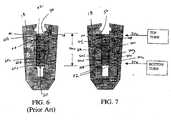
- the spacer blocks 30are shown at axially spaced locations between the end turns of the windings 28 of the coils. Note that the end turns are vertically aligned with parallel sides, typical of rotor configurations which employ parallel sided slots. The individual turns as they appear in the parallel sided slots of the rotor are shown in FIG. 6 . For rotors which have tapered slots, however, the end turns 29 typically appear as shown in FIG. 5 . Spacer blocks 32 are shown at axially spaced locations between end turns of the windings 29 of the coils.
- FIG. 6illustrates a conventional field winding copper construction wound on rotor body 18 having parallel sided slots 36, wherein the extruded copper has a substantially rectangular cross-sectional shape, including an upper side 42, a lower side 44 and opposite side edges 46 and 48.
- the slotcontains layers of copper turns separated by layers of turn insulation.
- the extruded copperis optionally subjected to a punching process in order to provide a plurality of axially spaced holes along the length of the copper generally indicated at 50.
- the corresponding aligned holes 50form a direct radial coolant passage which, in a typical generator configuration, extends from an inner axially extending sub-slot, to the air gap between the rotor and the stator.
- Individual windingsare separated by strips of insulation (not shown). As can be seen in FIG. 1 , many such radial ducts are provided along the length of the field winding copper and, for example, can be spaced as little as two inches apart.
- the rotor body 18is formed with parallel sided slots 36 with reference to FIG. 7 .
- the coil constructionis modified so that the eleven turns of windings 70a- 70k are of varying thickness of at least two different thicknesses, but all having substantially the same width corresponding to a constant width of the parallel sided slot 36 in which the turns are disposed.
- the slot width and the width of a field turnare not equal.
- an insulator, called slot armoris disposed in the slot insulating both sides of the field winding so that the field winding is aligned with, but not in contact with sidewalls or edges defining each slot.
- each opposing side edge 46, 48 of each turn 70a-70k having at least one of two different thickness as illustrated in FIG. 7is aligned along a corresponding common edge 72 defining a constant slot width (i.e. there is no taper) of each parallel sided slot 36 for purposes of reducing hot spot temperatures, which is a different design intent than that utilizing a tapered slot.
- Thicker turnsare disposed in regions of high temperature, for example, the top turns 70h-70k which generally exhibit higher temperatures in the class of electrical machines in which the variable turn thickness concept is contemplated (e.g., large steam-turbine generators).
- the increased cross sectional area afforded by the thicker copper turnsreduces the electrical resistance therethrough, and thus, local heat generation relative to using a thinner copper turn.
- a field winding design that utilizes more than one turn thickness to manage the heat generationreduces the localized maximum field temperature. Accordingly, replacing the layers of constant turn thickness turns (e.g., turns 60a-60k of FIG. 6 ) with layers of differing turn thickness, reduces local hot spot temperature by reducing the heat generation (i.e. by reducing the local resistance of the winding through increasing the copper cross-section area).
- increasing the copper cross-section area by replacement of the layers of constant turn thickness turns (e.g., turns 60a-60k of FIG. 6 ) with layers of differing turn thicknesscan be accomplished without increasing the number of turns and/or the net copper turn thickness (Net T ) of the copper turns as illustrated in FIG. 7 .
- FIGS. 8 and 9illustrate a three-dimensional detailed thermal analysis performed with respect generator rotor 18 being wound with a constant turn thickness as in FIG. 6 and with a multiple turn thickness as in FIG. 7 , representative of two concepts.
- the net copper thickness (Net T ), number of turns, slot geometry and turn insulation thicknessare identical in both cases.
- the only difference between the two conceptsis that one concept uses eleven turns of constant thickness and the second concept uses eleven turns of two different thickness.
- the hot spot temperature indicated by peak temperatures of the top turns or turns 9 and 11generally shown at 80 using a two turn thickness dropped by about 7 °C from that of using a constant turn thickness. More specifically, it will be noted that the peak temperatures 80 occur along a length of turn numbers 9 and 11, for example, at about 33 inches and at about 55 inches having a peak temperature of about 146 °C indicated with line 84 in FIG. 9 and about 153 °C indicated with line 86 in FIG. 8 .
- the slotcontained three or more turn thicknesses.
- a three copper turn thicknessis contemplated.
- Turns 8-11optionally having a copper thickness of 0.353 inches, turns 5-7 having a copper thickness of 0.323 inches, and turns 1-4 having a copper turn thickness of 0.293 inches, all turns having a width of about 1.514 inches, can be wound in a slot having a constant rotor duct width. As discussed above, it has been shown with reference to FIGS.
- a variable turn thicknessprovides less radial variation in temperature and reduced hot spot temperature along the coil side of the generator.
- variable width turns of variable thicknesstwo or more
- local heat generationis reduced in critical regions and is allowed to increase in less critical regions thereby obtaining an overall reduction in the hot spot temperature.
- This featureincreases the entitlement on ventilated field windings thereby enabling increased power density and possibly improved efficiency.
- local heat generationis reduced by reducing the local resistance of the winding through increasing the copper cross-section area by increasing only the thickness while maintaining a constant width of the copper turns.
Landscapes
- Engineering & Computer Science (AREA)
- Power Engineering (AREA)
- Windings For Motors And Generators (AREA)
- Manufacture Of Motors, Generators (AREA)
Description
- This invention relates generally to generator field windings and, more specifically, to generator field windings configured and disposed on a generator rotor in a manner to reduce hot spot temperatures.
- Generator rotors are provided with radial slots about the periphery thereof, for receiving field or rotor windings of coils made up of a number of turns in a radially stacked arrangement, each turn or winding separated by insulation. The windings are retained in the slots by full-length wedges, with creepage blocks interposed between the wedges and the windings.
- Generators currently available from the assignee of the present application are placed in three major design classifications based on the cooling medium used: air cooled, hydrogen cooled and liquid cooled. All hydrogen and water cooled generators use direct conductor cooling of the rotor winding for heat removal. Smaller two-pole and all four-pole generators use a radial flow design where hydrogen enters the windings through full length sub-slots and is discharged along the length of the rotor body through radial slots, machined or punched in the copper windings. The hydrogen passes from the conductors through the creepage blocks and wedges to an "air gap" between the rotor and the stator, where it is directed through the stator core to the hydrogen coolers.
- At higher generator ratings, and consequently longer rotor body lengths, a gap-pickup diagonal-flow cooling process is employed. In this scheme, cold hydrogen is scooped up in the air gap between the rotor and stator and driven diagonally inwardly through the rotor field turns to directly remove the heat. At the bottom of the slot, hydrogen gas is turned and passes diagonally outwardly through the field turns to the air gap in a discharge stator core section. The stator core ventilation is coordinated with the rotor cooling gas flow, thus creating an in and out flow of hydrogen through the stator core, through the rotor and returning to the hydrogen cooler through the core.
- The generator field windings consist of extruded copper that is drawn at a copper mill and then machined and fabricated into a usable coil. Within the last few years, these coils have been redesigned from square corner fabricated coils, to a "C" coil. The cross section of the copper to make these coils has essentially remained the same. The "C" coil has nevertheless been preferred because many benefits have been derived from that shape relating to cost, cycle time and quality. Nevertheless, in order to maintain a competitive stance in the marketplace, new copper designs are constantly being evaluated for increased performance. With the constant design changes, the cross sectional area of the copper has been increasing. When the thickness increases, radial air cooling ducts that are machined in by a punch operation become increasingly more difficult to produce. For example, conventional punch operations may produce an unacceptable bulge in a width dimension of the copper, and it is therefore necessary to create a ventilation scheme for the increasing cross sections of the copper windings without unacceptable bulges in the width dimension.
- Furthermore, a design requirement that must be met as part of the industry standards on electrical generators includes meeting specific temperature rise requirements within the capability of certain classes of insulation. One such design requirement is that the maximum field winding temperature stay below a certain limit. In many ventilated field windings, the hot spot temperature is the limiting factor in increasing power density. One method of reducing the hotspot includes increasing the ventilation flow and directing it to regions of high temperature. The disadvantage of increasing flow is that it increases the pumping and windage losses which directly reduce generator efficiency. Another method includes reducing the amount of heat generation in regions of high temperature. For example, one method of reducing the heat generation includes increasing the cross-section area of the field winding copper thereby reducing the resistance and the local heat generation.
- The assignee presently makes generator fields with a tapered slot to increase copper content thereby increasing the field thermal capability. In particular, recent generators that use the tapered slot field include tapered slots with either square corner field winding designs or c-coil field winding designs. The tapered slot designs require turns of variable width as a consequence of the slot geometry and may have in the past used thicker turns at the narrow portion of the taper. Furthermore, tapered slots are more costly to machine than parallel slots and turns of variable width in a stack are more complex for manufacturers to make and assemble.
JP 2002 078265 JP 54026404 - It is desired to reduce local hot spot temperatures on generator fields by reducing heat generation without utilizing variable width turns on a tapered slot design.
- The above discussed and other drawbacks and deficiencies are overcome or alleviated in accordance with the present invention by a method and apparatus for reducing field hot spot temperatures through varying the copper turn thickness.
- In a first embodiment there is a generator coil comprising: a plurality of stacked windings in a rotor where individual turns are stacked in parallel sided radial slots in the rotor, each successive turn having the same width, said width corresponding to a constant width of the parallel sided radial slots, wherein each turn comprises an axial length of copper having a generally rectangular cross-sectional shape, wherein a first turn has a first thickness and a second turn has a second thickness thicker than said first thickness, said second turn employed in regions of high temperature thereby reducing the temperature thereof in which a two turn thickness is employed in a corresponding parallel sided slot having eleven turns and wherein thicker turns are disposed in regions of higher temperature such that a hot spot temperature corresponding to said region of higher temperature is reduced by about 7 °C from that of using constant turn thickness.
- In a second embodiment there is a method to reduce field winding temperatures for windings in a rotor the method comprising; varying turn thickness of individual turns with at least two different thickness turns stacked in a parallel sided slot of the rotor, each successive turn having the same width, said width corresponding to a constant width of the parallel sided radial slots, wherein each turn comprises an axial length of copper having a generally rectangular cross-sectional shape; employing thicker individual turns in a region corresponding to a field hot spot to reduce resistance and local heat generation thereof employing a two turn thickness in a corresponding parallel sided slot having eleven turns and disposing thicker turns are disposed in regions of higher temperature such that a hot spot temperature corresponding to said region of higher temperature is reduced by about 7 °C from that of using constant turn thickness.
- More specifically, the concept being proposed capitalizes on the ability to reduce local hot spot temperature by reducing the local heat generation (i.e. by reducing the local resistance of the winding through increasing the copper cross-section area). Thus, in the broader aspects, the invention relates to an end turn arrangement for windings in a rotor where individual turns are stacked in parallel sided radial slots in the rotor, with successive turns having the same width in a radial inward direction, the end turns of the individual turns of each stack being aligned along both edges defining each slot, wherein the turn thickness is increased in regions of high temperature thereby reducing the temperature. An added benefit of having variable turn thickness is that it results in more uniform field temperatures which results in less thermal cycling, less fatigue, and longer part life as a result of the reduced temperature gradients between the field winding components.
- The above-discussed and other features and advantages of the present invention will be appreciated and understood by those skilled in the art from the following detailed description and the accompanying drawings, in which:
FIG. 1 is a side elevation view of a generator rotor having coil windings and retaining rings;FIG. 2 is a partial axial cross section of the rotor shown inFIG. 1 , illustrating a conventional coupling between a retaining ring and a rotor body taken along theline 2--2 ofFIG. 1 ;FIG. 3 is a schematic view of the end windings of a rotor, illustrating conventional blocking between adjacent end windings;FIG. 4 is a schematic axial section of the end windings of a rotor having parallel slots;FIG. 5 is a schematic view similar toFIG. 4 , but illustrating end windings for rotors with centered taper slots;FIG. 6 is a schematic diagram of eleven constant thickness turns in a parallel sided generator rotor slot;FIG. 7 is a schematic diagram similar toFIG. 6 but with eleven varying thickness turns in the parallel sided generator slot in accordance with an exemplary embodiment;FIG. 8 is a graph illustrating the temperature vs. the length of some of the eleven constant thickness turns ofFIG. 6 ; andFIG. 9 is a graph illustrating the temperature vs. the length of some of the eleven varying thickness turns ofFIG. 7 indicative of reduced temperatures associated with field hot spots in accordance with an exemplary embodiment.FIG. 1 illustrates aconventional rotor 10 for a generator (or motor). The rotor has ashaft 12 with a power turbine (or mechanical mode)coupling 14 and supported by bearings (not shown). Therotor shaft 12 also has acollector ring 16 that provides an electrical junction for the rotor field winding.- The rotor has a
large diameter body 18 that holds thecoil windings 20. The rotor body has longitudinally oriented slots extending radially outwardly from the center of therotor 10, and in which the individual turns of thewindings 20 are mounted. These slots extend the length of the rotor body, andannular retaining rings 22 cap both ends of therotor body 18. The retaining rings are supported at one end by the rotor body (seeFIG. 2 ). Adjacent theretaining rings 22 arefans 26 that cool the retaining rings and other rotor components. - As will be appreciated from
FIG. 2 , theretaining rings 22 slide over the end of therotor body 18 and are attached to therotor body 18 by a conventional shrink fit process. Theend turns 28 are enclosed by theretaining rings 22, which thus prevent radially outward movement of the end turns 28 by centrifugal forces generated by therotor 10. The end turns 28 extend circumferentially about the rotor and are axially spaced from one another, while the turns between the ends lie parallel to the rotor axis and are circumferentially spaced from each other. In each case, the spacing between adjacent coils is maintained by a predetermined distance by means ofblocks 30 as shown inFIG. 3 . - In
FIG. 4 , thespacer blocks 30 are shown at axially spaced locations between the end turns of thewindings 28 of the coils. Note that the end turns are vertically aligned with parallel sides, typical of rotor configurations which employ parallel sided slots. The individual turns as they appear in the parallel sided slots of the rotor are shown inFIG. 6 . For rotors which have tapered slots, however, the end turns 29 typically appear as shown inFIG. 5 . Spacer blocks 32 are shown at axially spaced locations between end turns of thewindings 29 of the coils. FIG. 6 illustrates a conventional field winding copper construction wound onrotor body 18 having parallelsided slots 36, wherein the extruded copper has a substantially rectangular cross-sectional shape, including anupper side 42, alower side 44 and opposite side edges 46 and 48. In conventional systems, the slot contains layers of copper turns separated by layers of turn insulation. The extruded copper is optionally subjected to a punching process in order to provide a plurality of axially spaced holes along the length of the copper generally indicated at 50. When a plurality of such field windings are stacked as shown inFIG. 6 at 60a, 60b, 60c, ....and 60k, the corresponding aligned holes 50 (e.g., 50a, 50b, 50c, ....and 50k, respectively), form a direct radial coolant passage which, in a typical generator configuration, extends from an inner axially extending sub-slot, to the air gap between the rotor and the stator. Individual windings are separated by strips of insulation (not shown). As can be seen inFIG. 1 , many such radial ducts are provided along the length of the field winding copper and, for example, can be spaced as little as two inches apart.- In accordance with an exemplary embodiment, the
rotor body 18 is formed with parallelsided slots 36 with reference toFIG. 7 . The coil construction is modified so that the eleven turns of windings 70a- 70k are of varying thickness of at least two different thicknesses, but all having substantially the same width corresponding to a constant width of the parallelsided slot 36 in which the turns are disposed. It will be recognized by one skilled in the pertinent art that the slot width and the width of a field turn are not equal. There is tolerance therebetween such that an insulator, called slot armor, is disposed in the slot insulating both sides of the field winding so that the field winding is aligned with, but not in contact with sidewalls or edges defining each slot. - In other words, each opposing
side edge FIG. 7 is aligned along a correspondingcommon edge 72 defining a constant slot width (i.e. there is no taper) of each parallelsided slot 36 for purposes of reducing hot spot temperatures, which is a different design intent than that utilizing a tapered slot. Thicker turns are disposed in regions of high temperature, for example, the top turns 70h-70k which generally exhibit higher temperatures in the class of electrical machines in which the variable turn thickness concept is contemplated (e.g., large steam-turbine generators). In this manner, the increased cross sectional area afforded by the thicker copper turns reduces the electrical resistance therethrough, and thus, local heat generation relative to using a thinner copper turn. A field winding design that utilizes more than one turn thickness to manage the heat generation reduces the localized maximum field temperature. Accordingly, replacing the layers of constant turn thickness turns (e.g., turns 60a-60k ofFIG. 6 ) with layers of differing turn thickness, reduces local hot spot temperature by reducing the heat generation (i.e. by reducing the local resistance of the winding through increasing the copper cross-section area). Moreover, it will be recognized that increasing the copper cross-section area by replacement of the layers of constant turn thickness turns (e.g., turns 60a-60k ofFIG. 6 ) with layers of differing turn thickness can be accomplished without increasing the number of turns and/or the net copper turn thickness (NetT) of the copper turns as illustrated inFIG. 7 . FIGS. 8 and 9 illustrate a three-dimensional detailed thermal analysis performed withrespect generator rotor 18 being wound with a constant turn thickness as inFIG. 6 and with a multiple turn thickness as inFIG. 7 , representative of two concepts. The net copper thickness (NetT), number of turns, slot geometry and turn insulation thickness are identical in both cases. The only difference between the two concepts is that one concept uses eleven turns of constant thickness and the second concept uses eleven turns of two different thickness.- Still referring to
FIGS. 6-9 , it will be recognized by one skilled in the pertinent art that the hot spot temperature indicated by peak temperatures of the top turns or turns 9 and 11 generally shown at 80 using a two turn thickness dropped by about 7 °C from that of using a constant turn thickness. More specifically, it will be noted that thepeak temperatures 80 occur along a length of turn numbers 9 and 11, for example, at about 33 inches and at about 55 inches having a peak temperature of about 146 °C indicated withline 84 inFIG. 9 and about 153 °C indicated withline 86 inFIG. 8 . - It is contemplated that a further reduction of hot spot temperature is possible if the slot contained three or more turn thicknesses. For example, in an alternative embodiment, a three copper turn thickness is contemplated. Turns 8-11 optionally having a copper thickness of 0.353 inches, turns 5-7 having a copper thickness of 0.323 inches, and turns 1-4 having a copper turn thickness of 0.293 inches, all turns having a width of about 1.514 inches, can be wound in a slot having a constant rotor duct width. As discussed above, it has been shown with reference to
FIGS. 8 and 9 that a minimum improvement of 7 °C is obtained using a two turn thickness instead of a constant turn thickness in a parallel sided slot, while more than a 7 °C reduction is contemplated when employing a three or more turn thickness. In turn, a variable turn thickness provides less radial variation in temperature and reduced hot spot temperature along the coil side of the generator. - By employing constant width turns of variable thickness (two or more) in a generator rotor, local heat generation is reduced in critical regions and is allowed to increase in less critical regions thereby obtaining an overall reduction in the hot spot temperature. This feature increases the entitlement on ventilated field windings thereby enabling increased power density and possibly improved efficiency. In particular, local heat generation is reduced by reducing the local resistance of the winding through increasing the copper cross-section area by increasing only the thickness while maintaining a constant width of the copper turns.
Claims (7)
- A generator coil comprising:a plurality of stacked windings in a rotor (10) where individual turns (70) are stacked in parallel sided radial slots (36) in the rotor (10), each successive turn (70) having the same width, said width corresponding to a constant width of the parallel sided radial slots (36), wherein each turn (70) comprises an axial length of copper having a generally rectangular cross-sectional shape, wherein a first turn (70) has a first thickness and a second turn (70) has a second thickness thicker than said first thickness, said second turn (70) employed in regions of high temperature thereby reducing the temperature thereof, whereina two turn thickness is employed in a corresponding parallel sided slot (36) having eleven turns (70) and wherein thicker turns are disposed in regions of higher temperature such that a hot spot temperature corresponding to said region of higher temperature is reduced by about 7 °C from that of using constant turn thickness.
- The generator coil of claim 1, wherein said second turn (70) is employed in at least one of a region of high temperature and top turns (70) (70h - k) of the rotor (10).
- The generator coil of claim 1, wherein said each slot (36) contains layers of said individual turns (70) comprising copper turns separated by layers of turn insulation.
- The generator coil of claim 3, wherein said layers of turn insulation disposed between said first and second turns (70) have substantially the same thickness.
- The generator coil of claim 1, wherein a net turn thickness and number of turns (70) are identical to that if a constant turn thickness was employed in said each slot (36) of identical geometry.
- The generator coil of claim 1, wherein at least two different turn thicknesses are employed.
- A method to reduce field winding temperatures for windings in a rotor (10) the method comprising:varying turn thickness of individual turns (70) with at least two different thickness turns (70) stacked in a parallel sided slot (36) of the rotor (10), each successive turn (70) having the same width, said width corresponding to a constant width of the parallel sided radial slots (36), wherein each turn (70) comprises an axial length of copper having a generally rectangular cross-sectional shape;employing thicker individual turns (70) in a region corresponding to a field hot spot to reduce resistance and local heat generation thereofcharacterised byemploying a two turn thickness in a corresponding parallel sided slot (36) having eleven turns (70) and disposing thicker turns in regions of higher temperature such that a hot spot temperature corresponding to said region of higher temperature is reduced by about 7 °C from that of using constant turn thickness.
Applications Claiming Priority (2)
| Application Number | Priority Date | Filing Date | Title |
|---|---|---|---|
| US707911 | 2004-01-23 | ||
| US10/707,911US6956313B2 (en) | 2004-01-23 | 2004-01-23 | Method and apparatus for reducing hot spot temperatures on stacked field windings |
Publications (3)
| Publication Number | Publication Date |
|---|---|
| EP1557929A2 EP1557929A2 (en) | 2005-07-27 |
| EP1557929A3 EP1557929A3 (en) | 2007-08-01 |
| EP1557929B1true EP1557929B1 (en) | 2011-08-10 |
Family
ID=34633170
Family Applications (1)
| Application Number | Title | Priority Date | Filing Date |
|---|---|---|---|
| EP05250185ACeasedEP1557929B1 (en) | 2004-01-23 | 2005-01-14 | Method and apparatus for reducing hot spot temperatures on stacked field windings |
Country Status (3)
| Country | Link |
|---|---|
| US (2) | US6956313B2 (en) |
| EP (1) | EP1557929B1 (en) |
| JP (1) | JP5038595B2 (en) |
Families Citing this family (30)
| Publication number | Priority date | Publication date | Assignee | Title |
|---|---|---|---|---|
| US7619512B2 (en)* | 2006-10-02 | 2009-11-17 | Alarm.Com | System and method for alarm signaling during alarm system destruction |
| DE102004058046B4 (en)* | 2004-12-01 | 2012-10-31 | Siemens Ag | High-pole permanent-magnet synchronous machine with toothed coils |
| FR2890798A1 (en)* | 2005-09-13 | 2007-03-16 | Valeo Equip Electr Moteur | STATOR FOR AN ALTERNATOR OR ALTERNO-STARTER TYPE POLYPHASE ELECTRICAL ROTATING MACHINE |
| US7928626B2 (en)* | 2006-04-28 | 2011-04-19 | Mitsubishi Cable Industries, Ltd. | Linear material and stator structure |
| US7521835B2 (en)* | 2006-06-27 | 2009-04-21 | General Electric Company | Permanent magnet machine with windings having strand transposition |
| JP2008131826A (en)* | 2006-11-24 | 2008-06-05 | Toyota Motor Corp | Motor stator and method for manufacturing motor stator |
| US7679507B2 (en) | 2007-05-16 | 2010-03-16 | Honeywell International Inc. | Video alarm verification |
| JP4486114B2 (en) | 2007-09-03 | 2010-06-23 | 株式会社日立製作所 | Rotating electric machine |
| US7755230B2 (en) | 2008-02-06 | 2010-07-13 | Hitachi, Ltd. | Rotary electric machine having cooling device and electric generating system including the machine |
| US7893576B2 (en)* | 2009-05-05 | 2011-02-22 | General Electric Company | Generator coil cooling baffles |
| US9680343B2 (en) | 2011-05-09 | 2017-06-13 | General Electric Company | Method and kit for upgrading a generator to enhance operation of the generator |
| US8729765B2 (en)* | 2011-07-26 | 2014-05-20 | GM Global Technology Operations LLC | Field coil for an electric machine |
| US20130093280A1 (en)* | 2011-10-17 | 2013-04-18 | GM Global Technology Operations LLC | Multi-filar bar conductors for electric machines |
| US8866361B2 (en)* | 2011-10-17 | 2014-10-21 | GM Global Technology Operations LLC | Bar conductor shapes for electric machines |
| JP5877035B2 (en)* | 2011-10-31 | 2016-03-02 | 株式会社ミツバ | Flat wire winding structure |
| EP2693607A1 (en)* | 2012-07-30 | 2014-02-05 | Siemens Aktiengesellschaft | Coil for an electric machine |
| US8978239B2 (en) | 2013-01-09 | 2015-03-17 | General Electric Company | Field coil winding assembly |
| CN104330663B (en)* | 2014-10-24 | 2015-12-02 | 南车株洲电力机车研究所有限公司 | A kind of on-line monitoring method of motor winding temperature rise and system |
| US11107602B2 (en) | 2016-11-08 | 2021-08-31 | Autonetworks Technologies, Ltd. | Electric wire conductor, covered electric wire, and wiring harness |
| DE102016123067A1 (en) | 2016-11-30 | 2018-05-30 | Dr. Ing. H.C. F. Porsche Aktiengesellschaft | Rod winding arrangement of a stator or a rotor of an electrical machine |
| JP7129612B2 (en)* | 2017-01-18 | 2022-09-02 | パナソニックIpマネジメント株式会社 | motor |
| EP3588744B1 (en)* | 2017-02-21 | 2022-09-07 | Panasonic Intellectual Property Management Co., Ltd. | Motor |
| US11196312B2 (en)* | 2017-02-21 | 2021-12-07 | Panasonic Intellectual Property Management Co., Ltd. | Motor |
| WO2020047663A1 (en) | 2018-09-05 | 2020-03-12 | Dpm Technologies Inc. | Systems and methods for intelligent energy storage and provisioning using an energy storage control system |
| CA3137550C (en) | 2019-04-23 | 2024-05-21 | Dpm Technologies Inc. | Fault tolerant rotating electric machine |
| EP4315556A1 (en) | 2021-05-04 | 2024-02-07 | Exro Technologies Inc. | Battery control systems and methods |
| JP2024518405A (en) | 2021-05-13 | 2024-05-01 | エクスロ テクノロジーズ インク. | Method and apparatus for driving coils of a polyphase electric machine - Patents.com |
| EP3961871B1 (en) | 2021-09-01 | 2024-05-29 | General Electric Technology GmbH | A system for supporting turns of generator rotor endwinding coils and a method for winding and rewinding of a power generator for a fossil or a nuclear power plant |
| CN120226235A (en)* | 2022-11-16 | 2025-06-27 | Lg麦格纳电子动力总成有限公司 | Stator and motor with same |
| DK181725B1 (en)* | 2023-04-27 | 2024-11-06 | Kk Wind Solutions As | Non-uniform electrical winding |
Citations (1)
| Publication number | Priority date | Publication date | Assignee | Title |
|---|---|---|---|---|
| DE3007853A1 (en)* | 1979-03-01 | 1980-09-11 | Elin Union Ag | AXIAL SECURING OF THE SHOCK ABSORBER IN TURBOG GENERATORS |
Family Cites Families (14)
| Publication number | Priority date | Publication date | Assignee | Title |
|---|---|---|---|---|
| FR630109A (en)* | 1926-04-16 | 1927-11-23 | Improvements to dynamo-electric machines and other electrical devices provided with grooves containing the conductors | |
| US2085099A (en)* | 1933-11-11 | 1937-06-29 | Westinghouse Electric & Mfg Co | Low loss armature coil |
| US2333575A (en)* | 1941-08-22 | 1943-11-02 | Westinghouse Electric & Mfg Co | Variable-speed induction-motor design and control |
| US3995180A (en)* | 1975-03-10 | 1976-11-30 | General Electric Company | Generator rotor outlets for increased ventilation |
| JPS5426404A (en)* | 1977-08-01 | 1979-02-28 | Toshiba Corp | Cylinder-shape rotor |
| US4473765A (en)* | 1982-09-30 | 1984-09-25 | General Electric Company | Electrostatic grading layer for the surface of an electrical insulation exposed to high electrical stress |
| US5065064A (en)* | 1990-05-31 | 1991-11-12 | General Electric Company | Rotor slot insulation in rotors with subslots |
| US5264750A (en)* | 1992-06-17 | 1993-11-23 | General Electric Company | Strain energy control plane for generator rotor field |
| US5421077A (en)* | 1994-05-18 | 1995-06-06 | General Electric Company | Method for the substitution of copper windings in generator rotor fields originally having aluminum windings |
| US5886434A (en) | 1997-03-20 | 1999-03-23 | General Electric Co. | Generator field turn copper |
| US5929550A (en)* | 1997-03-20 | 1999-07-27 | General Electric Co. | Ventilated creepage blocks |
| US5986380A (en) | 1998-08-26 | 1999-11-16 | General Electric Co. | Mechanical constraints for tapered end turns of a generator rotor |
| JP2000139050A (en)* | 1998-10-30 | 2000-05-16 | Hitachi Ltd | Rotating electric machine |
| JP2002078265A (en) | 2000-08-31 | 2002-03-15 | Hitachi Ltd | Rotating electric machine |
- 2004
- 2004-01-23USUS10/707,911patent/US6956313B2/ennot_activeExpired - Lifetime
- 2005
- 2005-01-14EPEP05250185Apatent/EP1557929B1/ennot_activeCeased
- 2005-01-21JPJP2005013595Apatent/JP5038595B2/ennot_activeExpired - Lifetime
- 2005-06-30USUS11/160,599patent/US20050275304A1/ennot_activeAbandoned
Patent Citations (1)
| Publication number | Priority date | Publication date | Assignee | Title |
|---|---|---|---|---|
| DE3007853A1 (en)* | 1979-03-01 | 1980-09-11 | Elin Union Ag | AXIAL SECURING OF THE SHOCK ABSORBER IN TURBOG GENERATORS |
Also Published As
| Publication number | Publication date |
|---|---|
| US20050275304A1 (en) | 2005-12-15 |
| EP1557929A3 (en) | 2007-08-01 |
| JP5038595B2 (en) | 2012-10-03 |
| JP2005210893A (en) | 2005-08-04 |
| US20050162032A1 (en) | 2005-07-28 |
| EP1557929A2 (en) | 2005-07-27 |
| US6956313B2 (en) | 2005-10-18 |
Similar Documents
| Publication | Publication Date | Title |
|---|---|---|
| EP1557929B1 (en) | Method and apparatus for reducing hot spot temperatures on stacked field windings | |
| US5329197A (en) | Generator rotor winding with two coils per slot | |
| US8115352B2 (en) | Dynamoelectric machine coil spacerblock having flow deflecting channel in coil facing surface thereof | |
| CA2399350C (en) | Flow-through spaceblocks with deflectors and method for increased electric generator endwinding cooling | |
| EP1346457B1 (en) | Spaceblock deflector for increased electric generator endwinding cooling | |
| EP1946427A1 (en) | Paddled rotor spaceblocks | |
| EP2244355B1 (en) | Dynamoelectric machine rotors having enhanced heat transfer and method therefor | |
| US7541714B2 (en) | Streamlined body wedge blocks and method for enhanced cooling of generator rotor | |
| US6495943B2 (en) | Spaceblock scoops for enhanced rotor cavity heat transfer | |
| US8525376B2 (en) | Dynamoelectric machine coil spaceblock having flow deflecting structure in coil facing surface thereof | |
| US20020079753A1 (en) | High thermal conductivity spaceblocks for increased electric generator rotor endwinding cooling | |
| EP2246963A2 (en) | Dynamoelectric Machine Coil Spaceblock Having Flow Deflecting Structure in Coil Facing Surface Thereof | |
| US11777373B2 (en) | Method of efficient thermal management of rotor in a high power generator |
Legal Events
| Date | Code | Title | Description |
|---|---|---|---|
| PUAI | Public reference made under article 153(3) epc to a published international application that has entered the european phase | Free format text:ORIGINAL CODE: 0009012 | |
| AK | Designated contracting states | Kind code of ref document:A2 Designated state(s):AT BE BG CH CY CZ DE DK EE ES FI FR GB GR HU IE IS IT LI LT LU MC NL PL PT RO SE SI SK TR | |
| AX | Request for extension of the european patent | Extension state:AL BA HR LV MK YU | |
| PUAL | Search report despatched | Free format text:ORIGINAL CODE: 0009013 | |
| AK | Designated contracting states | Kind code of ref document:A3 Designated state(s):AT BE BG CH CY CZ DE DK EE ES FI FR GB GR HU IE IS IT LI LT LU MC NL PL PT RO SE SI SK TR | |
| AX | Request for extension of the european patent | Extension state:AL BA HR LV MK YU | |
| 17P | Request for examination filed | Effective date:20080201 | |
| 17Q | First examination report despatched | Effective date:20080311 | |
| AKX | Designation fees paid | Designated state(s):CH DE GB LI | |
| GRAP | Despatch of communication of intention to grant a patent | Free format text:ORIGINAL CODE: EPIDOSNIGR1 | |
| GRAS | Grant fee paid | Free format text:ORIGINAL CODE: EPIDOSNIGR3 | |
| GRAA | (expected) grant | Free format text:ORIGINAL CODE: 0009210 | |
| AK | Designated contracting states | Kind code of ref document:B1 Designated state(s):CH DE GB LI | |
| REG | Reference to a national code | Ref country code:GB Ref legal event code:FG4D | |
| REG | Reference to a national code | Ref country code:CH Ref legal event code:NV Representative=s name:SERVOPATENT GMBH Ref country code:CH Ref legal event code:EP | |
| REG | Reference to a national code | Ref country code:DE Ref legal event code:R096 Ref document number:602005029397 Country of ref document:DE Effective date:20111006 | |
| PLBE | No opposition filed within time limit | Free format text:ORIGINAL CODE: 0009261 | |
| STAA | Information on the status of an ep patent application or granted ep patent | Free format text:STATUS: NO OPPOSITION FILED WITHIN TIME LIMIT | |
| 26N | No opposition filed | Effective date:20120511 | |
| REG | Reference to a national code | Ref country code:DE Ref legal event code:R097 Ref document number:602005029397 Country of ref document:DE Effective date:20120511 | |
| PGFP | Annual fee paid to national office [announced via postgrant information from national office to epo] | Ref country code:CH Payment date:20191224 Year of fee payment:16 | |
| PGFP | Annual fee paid to national office [announced via postgrant information from national office to epo] | Ref country code:DE Payment date:20191218 Year of fee payment:16 Ref country code:GB Payment date:20191223 Year of fee payment:16 | |
| REG | Reference to a national code | Ref country code:CH Ref legal event code:PCAR Free format text:NEW ADDRESS: WANNERSTRASSE 9/1, 8045 ZUERICH (CH) | |
| REG | Reference to a national code | Ref country code:DE Ref legal event code:R119 Ref document number:602005029397 Country of ref document:DE | |
| REG | Reference to a national code | Ref country code:CH Ref legal event code:PL | |
| GBPC | Gb: european patent ceased through non-payment of renewal fee | Effective date:20210114 | |
| PG25 | Lapsed in a contracting state [announced via postgrant information from national office to epo] | Ref country code:LI Free format text:LAPSE BECAUSE OF NON-PAYMENT OF DUE FEES Effective date:20210131 Ref country code:DE Free format text:LAPSE BECAUSE OF NON-PAYMENT OF DUE FEES Effective date:20210803 Ref country code:GB Free format text:LAPSE BECAUSE OF NON-PAYMENT OF DUE FEES Effective date:20210114 Ref country code:CH Free format text:LAPSE BECAUSE OF NON-PAYMENT OF DUE FEES Effective date:20210131 |