EP1556121B1 - Insufflation system with a multi-capacity tube - Google Patents
Insufflation system with a multi-capacity tubeDownload PDFInfo
- Publication number
- EP1556121B1 EP1556121B1EP03773150.2AEP03773150AEP1556121B1EP 1556121 B1EP1556121 B1EP 1556121B1EP 03773150 AEP03773150 AEP 03773150AEP 1556121 B1EP1556121 B1EP 1556121B1
- Authority
- EP
- European Patent Office
- Prior art keywords
- tubes
- tube
- capacity
- insufflation system
- insufflation
- Prior art date
- Legal status (The legal status is an assumption and is not a legal conclusion. Google has not performed a legal analysis and makes no representation as to the accuracy of the status listed.)
- Expired - Lifetime
Links
- 210000003200peritoneal cavityAnatomy0.000claimsdescription5
- 238000004891communicationMethods0.000claimsdescription2
- 239000012530fluidSubstances0.000claimsdescription2
- 239000007789gasSubstances0.000description41
- 238000002357laparoscopic surgeryMethods0.000description6
- 238000000034methodMethods0.000description6
- CURLTUGMZLYLDI-UHFFFAOYSA-NCarbon dioxideChemical compoundO=C=OCURLTUGMZLYLDI-UHFFFAOYSA-N0.000description4
- GQPLMRYTRLFLPF-UHFFFAOYSA-NNitrous OxideChemical compound[O-][N+]#NGQPLMRYTRLFLPF-UHFFFAOYSA-N0.000description4
- 208000005646PneumoperitoneumDiseases0.000description3
- 241001639412VerresSpecies0.000description3
- 210000000683abdominal cavityAnatomy0.000description3
- 238000005516engineering processMethods0.000description3
- 238000001802infusionMethods0.000description3
- 239000000463materialSubstances0.000description3
- XKRFYHLGVUSROY-UHFFFAOYSA-NArgonChemical compound[Ar]XKRFYHLGVUSROY-UHFFFAOYSA-N0.000description2
- 230000004888barrier functionEffects0.000description2
- 230000033228biological regulationEffects0.000description2
- 239000001569carbon dioxideSubstances0.000description2
- 229910002092carbon dioxideInorganic materials0.000description2
- 230000009977dual effectEffects0.000description2
- QSHDDOUJBYECFT-UHFFFAOYSA-NmercuryChemical compound[Hg]QSHDDOUJBYECFT-UHFFFAOYSA-N0.000description2
- 229910052753mercuryInorganic materials0.000description2
- 238000012544monitoring processMethods0.000description2
- 239000001272nitrous oxideSubstances0.000description2
- 230000000149penetrating effectEffects0.000description2
- 229920000915polyvinyl chloridePolymers0.000description2
- 239000004800polyvinyl chlorideSubstances0.000description2
- PYHRZPFZZDCOPH-QXGOIDDHSA-N(S)-amphetamine sulfateChemical compound[H+].[H+].[O-]S([O-])(=O)=O.C[C@H](N)CC1=CC=CC=C1.C[C@H](N)CC1=CC=CC=C1PYHRZPFZZDCOPH-QXGOIDDHSA-N0.000description1
- 208000029549Muscle injuryDiseases0.000description1
- 210000003815abdominal wallAnatomy0.000description1
- 238000013459approachMethods0.000description1
- 229910052786argonInorganic materials0.000description1
- 230000008859changeEffects0.000description1
- 230000008878couplingEffects0.000description1
- 238000010168coupling processMethods0.000description1
- 238000005859coupling reactionMethods0.000description1
- 230000007423decreaseEffects0.000description1
- 230000001419dependent effectEffects0.000description1
- 238000010586diagramMethods0.000description1
- 239000003814drugSubstances0.000description1
- 229940079593drugDrugs0.000description1
- 238000001914filtrationMethods0.000description1
- 239000003365glass fiberSubstances0.000description1
- 239000001307heliumSubstances0.000description1
- 229910052734heliumInorganic materials0.000description1
- SWQJXJOGLNCZEY-UHFFFAOYSA-Nhelium atomChemical compound[He]SWQJXJOGLNCZEY-UHFFFAOYSA-N0.000description1
- 230000002209hydrophobic effectEffects0.000description1
- 208000014674injuryDiseases0.000description1
- 238000003780insertionMethods0.000description1
- 230000037431insertionEffects0.000description1
- 239000012212insulatorSubstances0.000description1
- 238000012986modificationMethods0.000description1
- 230000004048modificationEffects0.000description1
- 210000000056organAnatomy0.000description1
- 229920001296polysiloxanePolymers0.000description1
- 230000002980postoperative effectEffects0.000description1
- 238000011084recoveryMethods0.000description1
- 238000000926separation methodMethods0.000description1
- 238000001356surgical procedureMethods0.000description1
- 210000001519tissueAnatomy0.000description1
- 208000037816tissue injuryDiseases0.000description1
- 230000008733traumaEffects0.000description1
- 238000012800visualizationMethods0.000description1
Images


Classifications
- A—HUMAN NECESSITIES
- A61—MEDICAL OR VETERINARY SCIENCE; HYGIENE
- A61M—DEVICES FOR INTRODUCING MEDIA INTO, OR ONTO, THE BODY; DEVICES FOR TRANSDUCING BODY MEDIA OR FOR TAKING MEDIA FROM THE BODY; DEVICES FOR PRODUCING OR ENDING SLEEP OR STUPOR
- A61M13/00—Insufflators for therapeutic or disinfectant purposes, i.e. devices for blowing a gas, powder or vapour into the body
- A61M13/003—Blowing gases other than for carrying powders, e.g. for inflating, dilating or rinsing
- A—HUMAN NECESSITIES
- A61—MEDICAL OR VETERINARY SCIENCE; HYGIENE
- A61M—DEVICES FOR INTRODUCING MEDIA INTO, OR ONTO, THE BODY; DEVICES FOR TRANSDUCING BODY MEDIA OR FOR TAKING MEDIA FROM THE BODY; DEVICES FOR PRODUCING OR ENDING SLEEP OR STUPOR
- A61M16/00—Devices for influencing the respiratory system of patients by gas treatment, e.g. ventilators; Tracheal tubes
- A61M16/20—Valves specially adapted to medical respiratory devices
- A61M16/201—Controlled valves
- A61M16/202—Controlled valves electrically actuated
- A—HUMAN NECESSITIES
- A61—MEDICAL OR VETERINARY SCIENCE; HYGIENE
- A61M—DEVICES FOR INTRODUCING MEDIA INTO, OR ONTO, THE BODY; DEVICES FOR TRANSDUCING BODY MEDIA OR FOR TAKING MEDIA FROM THE BODY; DEVICES FOR PRODUCING OR ENDING SLEEP OR STUPOR
- A61M16/00—Devices for influencing the respiratory system of patients by gas treatment, e.g. ventilators; Tracheal tubes
- A61M16/08—Bellows; Connecting tubes ; Water traps; Patient circuits
- A61M16/0816—Joints or connectors
- A61M16/0833—T- or Y-type connectors, e.g. Y-piece
- A—HUMAN NECESSITIES
- A61—MEDICAL OR VETERINARY SCIENCE; HYGIENE
- A61M—DEVICES FOR INTRODUCING MEDIA INTO, OR ONTO, THE BODY; DEVICES FOR TRANSDUCING BODY MEDIA OR FOR TAKING MEDIA FROM THE BODY; DEVICES FOR PRODUCING OR ENDING SLEEP OR STUPOR
- A61M16/00—Devices for influencing the respiratory system of patients by gas treatment, e.g. ventilators; Tracheal tubes
- A61M16/20—Valves specially adapted to medical respiratory devices
- A61M16/208—Non-controlled one-way valves, e.g. exhalation, check, pop-off non-rebreathing valves
- A61M16/209—Relief valves
- A—HUMAN NECESSITIES
- A61—MEDICAL OR VETERINARY SCIENCE; HYGIENE
- A61M—DEVICES FOR INTRODUCING MEDIA INTO, OR ONTO, THE BODY; DEVICES FOR TRANSDUCING BODY MEDIA OR FOR TAKING MEDIA FROM THE BODY; DEVICES FOR PRODUCING OR ENDING SLEEP OR STUPOR
- A61M2205/00—General characteristics of the apparatus
- A61M2205/75—General characteristics of the apparatus with filters
- A61M2205/7536—General characteristics of the apparatus with filters allowing gas passage, but preventing liquid passage, e.g. liquophobic, hydrophobic, water-repellent membranes
- A—HUMAN NECESSITIES
- A61—MEDICAL OR VETERINARY SCIENCE; HYGIENE
- A61M—DEVICES FOR INTRODUCING MEDIA INTO, OR ONTO, THE BODY; DEVICES FOR TRANSDUCING BODY MEDIA OR FOR TAKING MEDIA FROM THE BODY; DEVICES FOR PRODUCING OR ENDING SLEEP OR STUPOR
- A61M2205/00—General characteristics of the apparatus
- A61M2205/75—General characteristics of the apparatus with filters
- A61M2205/7545—General characteristics of the apparatus with filters for solid matter, e.g. microaggregates
Definitions
- the present inventionrelates to the field of surgical instruments, and in particular, relates to the technology and instrumentation used to achieve pneumoperitoneum during laparoscopy and laparoscopic surgery.
- laparoscopic surgeryto perform a variety of procedures.
- surgeonsBy manipulating laparoscopes and video telescopes, surgeons gain a visualization of the abdominal cavity while minimizing tissue and muscle injury that normally accompanies conventional invasive procedures.
- laparoscopyreduces patient trauma, decreases patient recovery time, and yields significant cost savings by reducing post-operative care.
- the abdominal wallis first raised from the organs enclosed in the abdominal cavity. Separation is conventionally attained by pressurizing the abdominal cavity with an insufflation gas. Typically, carbon dioxide or nitrous oxide is used.
- an insufflation gastypically, carbon dioxide or nitrous oxide is used.
- pneumoperitoneumThe presence of artificial gas in the peritoneal cavity to achieve exposure during laparoscopy is referred to as pneumoperitoneum.
- the equipment associated with laparoscopic proceduresincluding the use of standard single PVC tubing, sub-micron filters, and standard laparoscopic equipment such as fixed and rotating collar luers, verres needles, and trocars further restrict the infusion rate of the insufflation gas.
- One techniqueis to use an insufflator with two separate supply sources of insufflating gas, with each providing up to 20 liters or more of flow per minute.
- This type of insufflatorallows high flow rates to be provided so that pneumoperiteum may be maintained.
- This type of insufflatorrequires an insufflator capable of creating and controlling separate flow paths within the insufflator, and as a result increases the costs and complexity associated with the insufflator.
- US 3858572 Adiscloses an insufflations device having a gas reservoir and two body penetrating means with according connecting tubing.
- the turbinghas one tube connected to the gas reservoir, a Y-shaped connector and two tubes connecting therefrom to the penetrating means. All tubes are of equal dimension.
- DE 4219859 A1discloses an insufflator having a gas source, an insufflations needle or a trocar and a gas coupling therebetween.
- US 6299592 Adiscloses a laparoscopic insufflator with two gas delivery paths and a microprocessor controlled gas supply system.
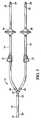
- FIGS. 1 and 2an embodiment of a dual-capacity tube 2 attached to an insufflator 4 is shown.
- the dual-capacity tube 2provides for the fluid communication of an insufflating gas between the insufflator 4 and laparoscopic equipment 3 that is inserted into a peritoneal cavity 5.
- the insufflator 4is a standard insufflator, such as the OMNIFLATOR Model 6620 available from Northgate Technologies, Inc, in Elgin, Illinois.
- the insufflator 4includes a pressurized source 6 of insufflation gas 8.
- insufflation gases 8include, but are not limited to, carbon dioxide, nitrous oxide, argon, or helium.
- the insufflation gas 8is reduced in pressure by the insufflator to approximately 45 through 55 millimeters of mercury (also known as a"push" pressure), although the pressure may be changed depending on the insufflator in use and any regulations that may be in force.
- the insufflation gas 8is delivered via a delivery assembly 10 to at least one output line 12 and passes from the insufflator 4 to the dual-capacity tube 2.
- the dual-capacity tube 2connects to a port 7 associated with the output line 12 of the insufflator 4.
- the delivery assembly 10is mainly comprised of electronics and pneumatics which, as noted above, are standard to the insufflator 4.
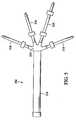
- the dual capacity tube 2includes a first tube 14 and a pair of tubes 16 attached to the first tube 14.
- a connector 18 on a first end 20 of the first tube 14is attached to the output line 12 of the insulator 4 via the port 7.
- Any suitable connector 18may be used, but the connector 18 should be of a type so the flow capacity of insufflation gas 8 from the output line 12 is not restricted. Examples of connectors include, but are not limited to, barb, spring- loaded, or quick-disconnect connectors.
- a second end 22 of the first tube 14is attached to a first end 24 of each of the pair of tubes 16 via an adapter 25.
- a connector 28is attached to a second end 30 of each of the pair of tubes 16. As with the connector 18 associated with the first end 20 of the first tube 14, the connector 28 should be of a type so the flow capacity of insufflation gas 8 from the output line 12 is not restricted.
- An example of a suitable connectoris a luer connector.
- the connectors 28 on the second end 30are for attachment with either laparoscopic equipment 3 or additional dual-capacity tubes 2. Examples of laparoscopic equipment 3 for attachment to the connector 28 on the second end 30 include verres needles, trocars, and canulas.
- the tubes 14, 16 of the dual-capacity tube 2should preferably be made from a flexible material.
- the tubes 14,16are disposable polyvinyl chloride tubes, although in other embodiments any suitable materials may be used.
- the tubingmay be made of a silicone material that is reusable.
- the first tube 14has an inner diameter approximately 9.5 mm (3/8 inches) and the pair of tubes 16 each normally has an inner diameter of approximately 6.35 mm (1/4 inches).
- the diameters of the tubes 14,16may be varied depending on flow rate requirements and any regulations that are in force.
- the inner diameter of each of the pair of tubes 16may be different from each other.
- the inner diameter of the first tube 14is larger than as the inner diameter of each of the pair of tubes 16.
- the pair of tubes 16should be sized so that they are each compatible with the laparoscopic equipment 3. For example, if each of the pair of tubes 16 has too large of an inner diameter, it will require a larger connector 28. If the connector 28 is too large, it will not be compatible with the laparoscopic equipment 3.
- a filter 26normally is located in each of the pair 16 of tubes to provide a particulate barrier. Alternatively, however, and as shown in FIG, 7 , one filter 26 may be located within the first tube.
- the filter 26is a glass-fiber hydrophobic filter that provides a particulate barrier of approximately 0.2 microns and operates at a ninety-nine percent rate of efficiency. In other embodiments any number of commonly used filters, with different filtering capabilities, may also be used.
- a valve 27is associated with at least one of the pair of tubes 16 and may restrict the flow of insufflation gas 8 in a closed or partially closed state, or may allow the free flow of gas in a fully open state. Although the present embodiment contemplates the valve 27 being located within one of the pair of tubes 16, in other embodiments the valve 27, such as the MEDEX Medical Valve, part no. B15061LG2, may be located within the connector 28 on the second end 30.
- the valveis operated electrically.
- the valvemay be a pressure relief valve.
- the valveopens and provides pressure relief.
- the valve 127may be operated by a signal generated by a controller 150 associated with the electronics of the insufflator 104.
- a controller 150associated with the electronics of the insufflator 104.
- An example of such a controlleris contained within the control circuitry of the Northgate OMNIFLATOR 6620 Insufflator, and an example of such a valve is a pinch valve.
- the signalis generated via feedback due to the monitoring of flow restriction or back pressure sensed by the controller 150.
- the monitoring of the pressure of the insufflation gasis accomplished via a pressure transducer (not shown) in the controller 150 that monitors the pressure in the dual-capacity tube 2.
- the dual-capacity tubeprovides for the flow of pressurized insufflation gas that exits from the insufflator.
- Each of the second ends 30has a connector 28 for the attachment of laparoscopic equipment 3 for insertion into a peritoneal cavity 5.
- the cavity 5is then inflated with the insufflation gas 8 flowing through the dual-capacity tube 2.
- insufflation gasinfused into the cavity at a higher rate, with 20 or more liters per minute being preferred.
- this gasis infused into the cavity using a standard single tube. Often, it is difficult to achieve this infusion rate using standard single tubes because of the limited push pressure provided by the insufflator.
- the tubeshould be of a size so that it is compatible with laparoscopic equipment.
- the laparoscopic equipmentcurrently available limits the flow rate of insufflation gas into a cavity to approximately 10- 15 liters per minute.
- the dual-capacity tubeprovides an inexpensive solution for facilitating a higher flow rate of insufflation gas.
- the larger first tube 14is of a size to allow insufflation gas 8 to flow at approximately 20 or more liters per minute.
- the presence of the pair of tubes 16, each sized to be compatible with laparoscopic equipment,will each normally allow approximately 10-15 liters per minute of insufflation gas to flow through the laparoscopic equipment and into the cavity.
- FIG. 5shows an additional embodiment of the dual-capacity tube.
- a multi-capacity tube 202is shown.
- the multi capacity tubehas a first tube 214 for attachment to an insufflator 104.
- This embodimentincludes a plurality of tubes 216 attached to the first tube 214 via an adapter 225.
- the inner diameter of the tubes 214,216should be similar to the sizes described above.
- Connectors, valves and other equipmentare also associated with the multi-capacity tube and are the similar to those described for the dual-capacity tube above.
- a higher flow rateis provided for with the multi-capacity tube in a manner similar to the example given above for the dual-capacity tube.
- additional dual- capacity tubes 2 or multi-capacity tubes 202may also be attached to the connector 28 on the second end 30 of at least one of the pair of tubes 16.
- additional dual-capacity tubes or multi-capacity tubesmay be attached to the multi-capacity tube associated with FIG. 5 .
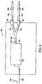
- FIG. 6shows an additional configuration of a dual capacity tube 302 and insufflator 304 to provide a higher infusion rate of gas into a cavity.
- the dual-capacity tubeis similar to the configuration associated with FIG. 3 , except that one of the pair of tubes 316 is a"stub"tube 317.
- the stub tube 317may be sized with respect to the other of the pair of tubes 316 and the first tube 314 as described above.
- a spike port 333is connected with a second end 331 of the stub tube 317.
- the other of the pair of tubes 316is configured as described above and may have a valve 327 associated with it.
- the first tube 314is attached to the port 307 of the insufflator 304.
- the spike port 333essentially seals the stub tube 317 and prevents the flow of insufflation gas from passing out of the stub tube 317.
- a spike 335may be used to pierce the spike port 333 of the stub tube 317.
- the spike 335has a spike tube 336 connected with it.
- the spike tube 336preferably has a connector 328 associated with it for the attachment of laparoscopic equipment.
- the spike 335has an internal through-path passing through it to allow the passage of insufflation gas from the stub tube 317 into the spike tube 336.
- a filter 326may be located within the first tube 314.
- a filtermay be located within the stub tube or the spike tube and the other of the pair of tubes.
- the stub tube 317, the spike tube 336, or the connector 328 associated with the spike tubemay also contain a valve 327 as described above.
- FIG. 6utilizes a dual- capacity tube
- other embodimentsmay use a multi-capacity tube that utilizes at least one stub tube.
- additional dual-capacity or multi-capacity tubesmay be attached to any dual-capacity or multi-capacity tubes that are being used with the insufflator in the manner described above.
- FIG. 8shows an additional configuration of a dual-capacity tube 402 and insufflator 404.
- the insufflator 404is the standard insufflator described above in connection with FIG. 2 , such as the OMNIFLATOR Model 6620 available from Northgate Technologies, Inc. in Elgin, Illinois, except that it has been slightly modified in as follows : a delivery port 420 has been added to the delivery assembly 410, and an additional output port 407 has been added so that there are now two output ports 407.
- the insufflator 404includes a pressurized source 406 of insufflation gas 408.
- the dual-capacity tube 402is connected within the insufflator 404 so that the first tube 414 is connected to the delivery port 420 associated with the delivery assembly 410 and the pair of tubes 416 is each connected to an output port 407.
- a pair of delivery tubes 422 each having a filter 426is attached to an output port 407.
- the insufflation gas 408is delivered via the delivery assembly 410 to the dual-capacity tube 402 to the delivery tubes 424.
- Laparoscopic equipment(not shown) may then be attached to each delivery tube in the manner described above.
- a single-output insufflatormay now provide two outputs for the delivery of insufflation gas.
- additional delivery ports and corresponding output portsmay be added to the insufflator so that additional dual-capacity tubes and delivery tubes may be attached.
- additional dual-capacity tubes and delivery tubesmay be attached to the delivery ports in the manner described above.
- FIG. 8The tubing and ports associated with FIG. 8 are the same as those described with the embodiments above. Additionally, filters may be attached to the dual-capacity tube in the ways described above either in lieu of or in addition to the filters associated with the delivery tubes.
Landscapes
- Health & Medical Sciences (AREA)
- Life Sciences & Earth Sciences (AREA)
- Public Health (AREA)
- Engineering & Computer Science (AREA)
- Anesthesiology (AREA)
- Biomedical Technology (AREA)
- Heart & Thoracic Surgery (AREA)
- Veterinary Medicine (AREA)
- Animal Behavior & Ethology (AREA)
- Hematology (AREA)
- General Health & Medical Sciences (AREA)
- Emergency Medicine (AREA)
- Pulmonology (AREA)
- Endoscopes (AREA)
- Surgical Instruments (AREA)
- External Artificial Organs (AREA)
Description
- The present invention relates to the field of surgical instruments, and in particular, relates to the technology and instrumentation used to achieve pneumoperitoneum during laparoscopy and laparoscopic surgery.
- Surgeons have used laparoscopic surgery to perform a variety of procedures. By manipulating laparoscopes and video telescopes, surgeons gain a visualization of the abdominal cavity while minimizing tissue and muscle injury that normally accompanies conventional invasive procedures. Compared to conventional surgery, laparoscopy reduces patient trauma, decreases patient recovery time, and yields significant cost savings by reducing post-operative care.
- The proper hardware and instrumentation are essential to the performance of laparoscopic procedures. To create a sufficient area for the introduction of a laparoscope and other instruments, the abdominal wall is first raised from the organs enclosed in the abdominal cavity. Separation is conventionally attained by pressurizing the abdominal cavity with an insufflation gas. Typically, carbon dioxide or nitrous oxide is used. The presence of artificial gas in the peritoneal cavity to achieve exposure during laparoscopy is referred to as pneumoperitoneum.
- When maintaining pneumoperitoneum, it is desirable on occasion to infuse the insufflation gas into the cavity at a rate typically above 20 liters per minute. Achieving this rate, however, often is difficult. One of the primary limitations in providing higher flows of insufflation gas are the constraints placed upon the insufflation equipment by both common industry practice, efficacy requirements, and guidance documents issued by the United States Food and Drug Administration concerning issues such as push pressures, pressure duration, overshoot, and pressure relief. Insufflators normally are limited to a push pressure of about 45 to 55 millimeters of mercury. This limitation makes it very difficult to infuse insufflation gas at the desired higher flow rates.
Furthermore, the equipment associated with laparoscopic procedures, including the use of standard single PVC tubing, sub-micron filters, and standard laparoscopic equipment such as fixed and rotating collar luers, verres needles, and trocars further restrict the infusion rate of the insufflation gas. - Several techniques have been used to attempt to overcome these limitations. One technique is to use an insufflator with two separate supply sources of insufflating gas, with each providing up to 20 liters or more of flow per minute. This type of insufflator allows high flow rates to be provided so that pneumoperiteum may be maintained. This type of insufflator, however, requires an insufflator capable of creating and controlling separate flow paths within the insufflator, and as a result increases the costs and complexity associated with the insufflator.
- Another approach has been to create very large, low restriction paths within an insufflator, large output lines on the front of the insufflators. This type of insufflator, however, requires the use of much larger, non-standard tubing. Also, non-standard, large-opening, expensive trocars and or verres needles are required. Presently, these are not readily available or are not disposable as are the instruments currently in use.
- Accordingly, it is desirable to have a device that overcomes the disadvantages and limitations described above.
US 3858572 A discloses an insufflations device having a gas reservoir and two body penetrating means with according connecting tubing. The turbing has one tube connected to the gas reservoir, a Y-shaped connector and two tubes connecting therefrom to the penetrating means. All tubes are of equal dimension.DE 4219859 A1 discloses an insufflator having a gas source, an insufflations needle or a trocar and a gas coupling therebetween.US 6299592 A discloses a laparoscopic insufflator with two gas delivery paths and a microprocessor controlled gas supply system. - In order to address the need for an improved apparatus to provide a higher flow rate of insufflation gas, a novel insufflation system is described below.
The insufflation system having the features as set out in claim 1 is provided.
Embodiments of the invention are further specified in the dependent claims. FIG. 1 is a view of a first embodiment of a dual-capacity tube and an insufflator;FIG. 2 is a view of the insufflator ofFIG. 1 ;FIG. 3 is a view of the dual-capacity tube ofFIG. 1 ;FIG. 4 is a diagram of a second embodiment of an insufflator and dual-capacity tube showing a feedback loop;FIG, 5 is a view of a multi-capacity tube;FIG. 6 is a view of an alternate configuration of the dual-capacity tube and the insufflator ofFIG. 1 ;FIG. 7 is a view of an alternate configuration of the dual-capacity tube ofFIG, 3 ; andFIG. 8 is a view of an additional embodiment of a dual-capacity tube and an insufflator.- Referring to
FIGS. 1 and2 , an embodiment of a dual-capacity tube 2 attached to aninsufflator 4 is shown. As will be discussed further below, the dual-capacity tube 2 provides for the fluid communication of an insufflating gas between theinsufflator 4 andlaparoscopic equipment 3 that is inserted into a peritoneal cavity 5. - The
insufflator 4 is a standard insufflator, such as the OMNIFLATOR Model 6620 available from Northgate Technologies, Inc, in Elgin, Illinois. Theinsufflator 4 includes a pressurized source 6 of insufflation gas 8. Examples of insufflation gases 8 include, but are not limited to, carbon dioxide, nitrous oxide, argon, or helium. The insufflation gas 8 is reduced in pressure by the insufflator to approximately 45 through 55 millimeters of mercury (also known as a"push" pressure), although the pressure may be changed depending on the insufflator in use and any regulations that may be in force. The insufflation gas 8 is delivered via adelivery assembly 10 to at least oneoutput line 12 and passes from theinsufflator 4 to the dual-capacity tube 2. The dual-capacity tube 2 connects to aport 7 associated with theoutput line 12 of theinsufflator 4. Thedelivery assembly 10 is mainly comprised of electronics and pneumatics which, as noted above, are standard to theinsufflator 4. - Referring to
FIG. 3 , thedual capacity tube 2 includes afirst tube 14 and a pair oftubes 16 attached to thefirst tube 14. Aconnector 18 on afirst end 20 of thefirst tube 14 is attached to theoutput line 12 of theinsulator 4 via theport 7. Anysuitable connector 18 may be used, but theconnector 18 should be of a type so the flow capacity of insufflation gas 8 from theoutput line 12 is not restricted. Examples of connectors include, but are not limited to, barb, spring- loaded, or quick-disconnect connectors. Asecond end 22 of thefirst tube 14 is attached to afirst end 24 of each of the pair oftubes 16 via anadapter 25. Although a stepped adapter, also referred to as a barbed adapter, is contemplated for use with the present embodiment, in other embodiments any suitable adapter may be used such as a tapered connector allowing for a "pressed"or bonded fit.
Aconnector 28 is attached to asecond end 30 of each of the pair oftubes 16. As with theconnector 18 associated with thefirst end 20 of thefirst tube 14, theconnector 28 should be of a type so the flow capacity of insufflation gas 8 from theoutput line 12 is not restricted. An example of a suitable connector is a luer connector. Theconnectors 28 on thesecond end 30 are for attachment with eitherlaparoscopic equipment 3 or additional dual-capacity tubes 2. Examples oflaparoscopic equipment 3 for attachment to theconnector 28 on thesecond end 30 include verres needles, trocars, and canulas. - The
tubes capacity tube 2 should preferably be made from a flexible material. In the present embodiment, thetubes first tube 14 has an inner diameter approximately 9.5 mm (3/8 inches) and the pair oftubes 16 each normally has an inner diameter of approximately 6.35 mm (1/4 inches). Of course, the diameters of thetubes tubes 16 may be different from each other. To achieve the greatest benefits of a higher flow rate, however, the inner diameter of thefirst tube 14 is larger than as the inner diameter of each of the pair oftubes 16. Moreover, the pair oftubes 16 should be sized so that they are each compatible with thelaparoscopic equipment 3. For example, if each of the pair oftubes 16 has too large of an inner diameter, it will require alarger connector 28. If theconnector 28 is too large, it will not be compatible with thelaparoscopic equipment 3.
Afilter 26 normally is located in each of thepair 16 of tubes to provide a particulate barrier. Alternatively, however, and as shown inFIG, 7 , onefilter 26 may be located within the first tube. In one embodiment, thefilter 26 is a glass-fiber hydrophobic filter that provides a particulate barrier of approximately 0.2 microns and operates at a ninety-nine percent rate of efficiency. In other embodiments any number of commonly used filters, with different filtering capabilities, may also be used.
Avalve 27 is associated with at least one of the pair oftubes 16 and may restrict the flow of insufflation gas 8 in a closed or partially closed state, or may allow the free flow of gas in a fully open state. Although the present embodiment contemplates thevalve 27 being located within one of the pair oftubes 16, in other embodiments thevalve 27, such as the MEDEX Medical Valve, part no. B15061LG2, may be located within theconnector 28 on thesecond end 30. - The valve is operated electrically. In other embodiments, the valve may be a pressure relief valve. When the pressure of the insufflation gas within the dual-capacity tube reaches a preset pressure, the valve opens and provides pressure relief. In additional embodiments as shown in
FIG. 4 , thevalve 127 may be operated by a signal generated by acontroller 150 associated with the electronics of theinsufflator 104. An example of such a controller is contained within the control circuitry of the Northgate OMNIFLATOR 6620 Insufflator, and an example of such a valve is a pinch valve. The signal is generated via feedback due to the monitoring of flow restriction or back pressure sensed by thecontroller 150. The monitoring of the pressure of the insufflation gas is accomplished via a pressure transducer (not shown) in thecontroller 150 that monitors the pressure in the dual-capacity tube 2. - As noted above, the dual-capacity tube provides for the flow of pressurized insufflation gas that exits from the insufflator. Each of the second ends 30 has a
connector 28 for the attachment oflaparoscopic equipment 3 for insertion into a peritoneal cavity 5. The cavity 5 is then inflated with the insufflation gas 8 flowing through the dual-capacity tube 2. When laparoscopic surgery is being performed, normally it is desirable to have insufflation gas infused into the cavity at a higher rate, with 20 or more liters per minute being preferred. Typically, this gas is infused into the cavity using a standard single tube. Often, it is difficult to achieve this infusion rate using standard single tubes because of the limited push pressure provided by the insufflator. Moreover, as noted above, the tube should be of a size so that it is compatible with laparoscopic equipment. Generally, the laparoscopic equipment currently available limits the flow rate of insufflation gas into a cavity to approximately 10- 15 liters per minute.
Because of its configuration, the dual-capacity tube provides an inexpensive solution for facilitating a higher flow rate of insufflation gas. For example, the largerfirst tube 14 is of a size to allow insufflation gas 8 to flow at approximately 20 or more liters per minute. The presence of the pair oftubes 16, each sized to be compatible with laparoscopic equipment, will each normally allow approximately 10-15 liters per minute of insufflation gas to flow through the laparoscopic equipment and into the cavity. The presence of a pair of tubes thus provides for a total flow rate of 20 or more liters of insufflation gas per minute. In other embodiments, where the tubes are of a different size or a different flow rate is desired, the dual-capacity tube provides for a higher rate of flow in a similar manner.FIG. 5 shows an additional embodiment of the dual-capacity tube. Amulti-capacity tube 202 is shown. As with the embodiment shown inFIG. 3 , the multi capacity tube has afirst tube 214 for attachment to aninsufflator 104. This embodiment, however, includes a plurality oftubes 216 attached to thefirst tube 214 via anadapter 225. The inner diameter of the tubes 214,216 should be similar to the sizes described above. Connectors, valves and other equipment are also associated with the multi-capacity tube and are the similar to those described for the dual-capacity tube above. A higher flow rate is provided for with the multi-capacity tube in a manner similar to the example given above for the dual-capacity tube. - In addition to attaching laparoscopic equipment, additional dual-
capacity tubes 2 ormulti-capacity tubes 202 may also be attached to theconnector 28 on thesecond end 30 of at least one of the pair oftubes 16. Thus, an additional embodiment is contemplated that provides for a multi-capacity tubing configuration. Moreover, additional dual-capacity tubes or multi-capacity tubes may be attached to the multi-capacity tube associated withFIG. 5 . FIG. 6 shows an additional configuration of adual capacity tube 302 andinsufflator 304 to provide a higher infusion rate of gas into a cavity. The dual-capacity tube is similar to the configuration associated withFIG. 3 , except that one of the pair oftubes 316 is a"stub"tube 317. Thestub tube 317 may be sized with respect to the other of the pair oftubes 316 and thefirst tube 314 as described above. Aspike port 333 is connected with asecond end 331 of thestub tube 317. The other of the pair oftubes 316 is configured as described above and may have avalve 327 associated with it. As in the embodiment inFIG. 3 , thefirst tube 314 is attached to theport 307 of theinsufflator 304. Thespike port 333 essentially seals thestub tube 317 and prevents the flow of insufflation gas from passing out of thestub tube 317. When a greater flow rate is desired, i. e., when it is desired to have insufflation gas passing through both of the pair oftubes 316, aspike 335 may be used to pierce thespike port 333 of thestub tube 317. Thespike 335 has aspike tube 336 connected with it. Thespike tube 336 preferably has aconnector 328 associated with it for the attachment of laparoscopic equipment. Thespike 335 has an internal through-path passing through it to allow the passage of insufflation gas from thestub tube 317 into thespike tube 336.- As with the embodiments described above, a
filter 326 may be located within thefirst tube 314. Alternatively, a filter may be located within the stub tube or the spike tube and the other of the pair of tubes. In addition, thestub tube 317, thespike tube 336, or theconnector 328 associated with the spike tube may also contain avalve 327 as described above. - Although the embodiment associated with
FIG. 6 utilizes a dual- capacity tube, other embodiments may use a multi-capacity tube that utilizes at least one stub tube. Furthermore, additional dual-capacity or multi-capacity tubes may be attached to any dual-capacity or multi-capacity tubes that are being used with the insufflator in the manner described above. FIG. 8 shows an additional configuration of a dual-capacity tube 402 andinsufflator 404. Theinsufflator 404 is the standard insufflator described above in connection withFIG. 2 , such as the OMNIFLATOR Model 6620 available from Northgate Technologies, Inc. in Elgin, Illinois, except that it has been slightly modified in as follows : adelivery port 420 has been added to thedelivery assembly 410, and anadditional output port 407 has been added so that there are now twooutput ports 407. As described above, theinsufflator 404 includes apressurized source 406 ofinsufflation gas 408. In this embodiment, the dual-capacity tube 402 is connected within theinsufflator 404 so that thefirst tube 414 is connected to thedelivery port 420 associated with thedelivery assembly 410 and the pair oftubes 416 is each connected to anoutput port 407.
A pair ofdelivery tubes 422 each having afilter 426 is attached to anoutput port 407. Theinsufflation gas 408 is delivered via thedelivery assembly 410 to the dual-capacity tube 402 to the delivery tubes 424. Laparoscopic equipment (not shown) may then be attached to each delivery tube in the manner described above. Thus, a single-output insufflator may now provide two outputs for the delivery of insufflation gas.- In alternate embodiments, additional delivery ports and corresponding output ports may be added to the insufflator so that additional dual-capacity tubes and delivery tubes may be attached. Moreover, although the embodiment associated with
FIG. 8 utilizes a dual-capacity tube, other embodiments may use a multi-capacity tube. Furthermore, additional dual- capacity or multi-capacity tubes may be attached to the delivery ports in the manner described above. - The tubing and ports associated with
FIG. 8 are the same as those described with the embodiments above. Additionally, filters may be attached to the dual-capacity tube in the ways described above either in lieu of or in addition to the filters associated with the delivery tubes. - While the above description constitutes the presently preferred embodiments of the invention, it will be appreciated that the invention is susceptible of modification, variation, and change without departing from the proper scope and fair meaning of the accompanying claims.
Claims (12)
- An insufflation system comprising:- an insufflator (4, 104, 304) having a delivery assembly for delivering insufflating gas from a pressurized source (6) of insufflation gas (8) to at least one gas delivery path;- at least one output line (12) coupled to the at least one gas delivery path;- at least one multi-capacity tube (202, 302) having:- - a first tube (214, 314) with a first end coupled to the at least one output line (12) and a second end connected to a first end of an adapter (225), and- - at least two second tubes (216, 316) each having a first end attached to a second end of the adapter (225) and a second end having a connector (328);- a laparoscopic component (3) attached to the connector (328) of at least one of the at least two second tubes (216, 316); and- at least one valve (127,327) attached to each of the at least two second tubes (216, 316) for controlling the flow of insufflating gas; wherein the at least one multi-capacity tube (202, 302) is configured to provide fluid communication of the insufflating gas between the insufflator and the laparoscopic component (3) that is insertable into a peritoneal cavity;characterised in that- the at least one valve (127,327) operates electrically; and- an inner diameter of the first tube (214, 314) is greater than an inner diameter of each of the second tubes (216, 316), and the second tubes (216, 316) are sized to provide a total flow rate of at least 20 litres per minute of insufflating gas to the peritoneal cavity.
- The insufflation system of claim 1, wherein the insufflator (4,104, 304) further comprises a controller (150) and wherein the at least one valve (127,327) operates via a signal from the controller (150).
- The insufflation system of claim 1, wherein the at least one valve (127,327) is a pressure relief valve that provides pressure relief when the insufflation gas reaches a predetermined pressure.
- The insufflation system of claim 1, wherein the at least one multi-capacity tube (202, 302) further comprises a filter (26) located within each of the more than two second tubes (216, 316).
- The insufflation system of claim 1, wherein the at least one multi-capacity tube (202, 302) further comprises a filter (206) located within the first tube (214, 314).
- The insufflation system of claim 1, wherein the at least one multi-capacity tube (202, 302) is disposable.
- The insufflation system of claim 1 wherein the at least one multi-capacity tube (202, 302) comprises more than two second tubes (216, 316) and the insufflation system further comprises a second multi-capacity tube (202, 302) having a first tube (214, 314) that includes a first end, wherein the first end of the second multi-capacity tube (202, 302) is attached to the connector (328) of one of the more than two second tubes (216, 316) of the at least one multi-capacity tube (202, 302).
- The insufflation system of claim 1, wherein the first tube (214, 314) of the at least one multi-capacity tube (202, 302) has an inner diameter of approximately 9.525mm (3/8 inches) and wherein the more than two second tubes each has an inner diameter of approximately 6.35mm (1/4 inches).
- The insufflation system of claim 8, wherein the inner diameter of each of the more than two second tubes (216, 316) is different from the others of the more than two second tubes (216, 316).
- The insufflation system of claim 1, wherein the first tube (214, 314) is attached to more than two second tubes (216, 316) and the adapter (225) is a stepped adapter (225).
- The insufflation system of claim 1 comprising more than two second tubes (216, 316) and further comprising at least one spike port (333) attached with the second end of one of the at least more than two second tubes (216, 316), wherein the spike port (333) is configured to prevent the flow of the insufflation gas through the attached one of the at least more than two second tubes (216, 316) until the at least one spike port (333) is opened.
- The insufflation system of claim 1, wherein the multi-capacity tube (202) has four second tubes (216).
Applications Claiming Priority (3)
| Application Number | Priority Date | Filing Date | Title |
|---|---|---|---|
| US42166202P | 2002-10-28 | 2002-10-28 | |
| US421662P | 2002-10-28 | ||
| PCT/US2003/031524WO2004039415A2 (en) | 2002-10-28 | 2003-10-28 | Dual-capacity insufflator tube |
Related Child Applications (1)
| Application Number | Title | Priority Date | Filing Date |
|---|---|---|---|
| EP13162341Division-Into | 2013-04-04 |
Publications (3)
| Publication Number | Publication Date |
|---|---|
| EP1556121A2 EP1556121A2 (en) | 2005-07-27 |
| EP1556121A4 EP1556121A4 (en) | 2010-04-14 |
| EP1556121B1true EP1556121B1 (en) | 2016-06-01 |
Family
ID=32230246
Family Applications (1)
| Application Number | Title | Priority Date | Filing Date |
|---|---|---|---|
| EP03773150.2AExpired - LifetimeEP1556121B1 (en) | 2002-10-28 | 2003-10-28 | Insufflation system with a multi-capacity tube |
Country Status (4)
| Country | Link |
|---|---|
| US (2) | US20040153027A1 (en) |
| EP (1) | EP1556121B1 (en) |
| AU (1) | AU2003279823A1 (en) |
| WO (1) | WO2004039415A2 (en) |
Families Citing this family (21)
| Publication number | Priority date | Publication date | Assignee | Title |
|---|---|---|---|---|
| EP1556121B1 (en) | 2002-10-28 | 2016-06-01 | Northgate Technologies Incorporated | Insufflation system with a multi-capacity tube |
| JP4573554B2 (en)* | 2004-03-30 | 2010-11-04 | オリンパス株式会社 | Endoscopic surgery system |
| JP2006061214A (en)* | 2004-08-24 | 2006-03-09 | Olympus Corp | Surgery system |
| DE102005052122A1 (en)* | 2005-10-28 | 2007-05-10 | W.O.M. World Of Medicine Ag | tubing |
| EP2056922B1 (en)* | 2006-08-04 | 2018-03-28 | Northgate Technologies, Inc. | In-dwelling port for access into a body |
| US20090241948A1 (en)* | 2007-03-28 | 2009-10-01 | Dermot Joseph Clancy | Humidification in breathing circuits |
| WO2008117264A1 (en)* | 2007-03-28 | 2008-10-02 | Stamford Devices Limited | Insufflation of body cavities |
| US20090093683A1 (en)* | 2007-10-05 | 2009-04-09 | Tyco Healthcare Group Lp | Surgical portal kit for use in single incision surgery |
| JP5733831B2 (en)* | 2008-10-10 | 2015-06-10 | サージクェスト,インコーポレーテッド | System and method for improved gas recirculation in a surgical trocar with a gas sealing mechanism |
| DE102009007393A1 (en)* | 2009-01-29 | 2010-08-05 | Mgb Endoskopische Geräte Gmbh Berlin | insufflator |
| US8939971B2 (en)* | 2011-03-11 | 2015-01-27 | Minerva Surgical, Inc. | System and method for endometrial ablation |
| DE102012009078A1 (en)* | 2012-05-09 | 2013-11-14 | Karl Storz Gmbh & Co. Kg | Insufflation device and method |
| US9017281B2 (en)* | 2012-09-07 | 2015-04-28 | Surgiquest, Inc. | System having multiple pneumatically sealed trocars |
| US9849263B2 (en)* | 2013-03-12 | 2017-12-26 | Touchfree O2 Llc | Method and device for supplying oxygen to a patient |
| US9572595B1 (en) | 2014-03-05 | 2017-02-21 | Northgate Technologies Inc. | In-dwelling port for access into a body |
| US10159809B2 (en)* | 2015-01-30 | 2018-12-25 | Surgiquest, Inc. | Multipath filter assembly with integrated gaseous seal for multimodal surgical gas delivery system |
| EP3656428B1 (en)* | 2015-09-30 | 2021-06-16 | Applied Medical Resources Corporation | Insufflation stabilization system |
| US11497565B2 (en)* | 2016-06-07 | 2022-11-15 | Corindus, Inc. | Device drive for catheter procedure system |
| WO2020188803A1 (en)* | 2019-03-20 | 2020-09-24 | オリンパス株式会社 | Gas feed system |
| US11541191B2 (en)* | 2019-05-09 | 2023-01-03 | Lexion Medical, Llc | Distributed flow path insufflation |
| WO2023056415A1 (en)* | 2021-09-30 | 2023-04-06 | Duke University | Multi-port, high-flow pneumoperitoneum and smoke evacuation distribution devices, systems, and methods |
Family Cites Families (62)
| Publication number | Priority date | Publication date | Assignee | Title |
|---|---|---|---|---|
| US3853105A (en) | 1971-12-16 | 1974-12-10 | P Kenagy | Insufflator gas flow device |
| US3858572A (en)* | 1972-10-27 | 1975-01-07 | Kendall & Co | Insufflation device |
| DE2451383C3 (en) | 1974-10-26 | 1979-05-03 | Hans-Joachim Dr.Med. 2000 Hamburg Lindemann | Regulator for an insufflation device |
| US4109656A (en) | 1977-02-07 | 1978-08-29 | Sybron Corporation | Apparatus for use with insufflators |
| US4464169A (en)* | 1981-10-15 | 1984-08-07 | Kurt Semm | Apparatus and method for insufflating fluid media into a cavity |
| DE3413631A1 (en) | 1984-04-11 | 1985-10-24 | Semm, Kurt, Prof. Dr.Med., 2300 Kiel | MONOFILE DEVICE FOR INSUFFLING GAS |
| US4715372A (en)* | 1985-06-12 | 1987-12-29 | Philippbar Jay E | Gas insufflation apparatus for use with an arthroscopic laser system |
| US4895562A (en)* | 1986-06-06 | 1990-01-23 | Icu Medical, Inc. | System for administering medication nasally to a patient |
| US4878894A (en) | 1987-02-26 | 1989-11-07 | Sutter Leroy V | Gas/saline valve with suction control |
| IT1222509B (en) | 1987-08-17 | 1990-09-05 | Miat Spa | INSUFFLATOR FOR THE ADMINISTRATION OF DRUGS IN THE FORM OF PRE-DOSED POWDER IN OPERATIONS |
| DE3739003A1 (en) | 1987-11-17 | 1989-05-24 | Wolf Gmbh Richard | INSUFFLATION DEVICE FOR ENDOSCOPIC INTERVENTIONS |
| DE3741149A1 (en) | 1987-12-04 | 1989-06-15 | Thomae Gmbh Dr K | PREPARATION FORMS FOR PREVENTING ADHAESIONS OF ORGANS AND ORGAN PARTS |
| US4911926A (en) | 1988-11-16 | 1990-03-27 | Mediventures Inc. | Method and composition for reducing postsurgical adhesions |
| DE4019239C2 (en) | 1990-06-15 | 1997-04-10 | Walz Elektronik Gmbh | Insufflation device |
| IT1248059B (en) | 1991-06-14 | 1995-01-05 | Miat Spa | MULTI-DOSE INSUFFLATOR FOR POWDER DRUGS |
| US5328458A (en) | 1991-12-03 | 1994-07-12 | Olympus Optical Co., Ltd. | Insufflation apparatus |
| US5814012A (en) | 1992-03-16 | 1998-09-29 | Birtcher Medical Systems, Inc. | Method and apparatus for relieving excess insufflation pressure |
| DE4211986A1 (en) | 1992-04-09 | 1993-10-14 | Wisap Gmbh | Heating device |
| US5292304A (en) | 1992-06-02 | 1994-03-08 | Northgate Technologies, Inc. | Insufflator digital gas flow system |
| DE4219859B4 (en)* | 1992-06-17 | 2005-12-29 | Erbe Elektromedizin Gmbh | insufflator |
| AU4543193A (en) | 1992-06-22 | 1994-01-24 | Henry E. Young | Scar inhibitory factor and use thereof |
| JPH07508443A (en) | 1992-07-07 | 1995-09-21 | 544456 ビー シー リミテッド | Venting methods and devices |
| US5246419A (en)* | 1992-09-04 | 1993-09-21 | Omnivision, Inc. | Intra-abdominal insufflation apparatus |
| US5363839A (en) | 1992-09-21 | 1994-11-15 | Jedmed Instrument Company | Video otoscope |
| US5399159A (en) | 1993-03-30 | 1995-03-21 | Origin Medsystems, Inc. | Apparatus and method for hand-held insufflation |
| US5515860A (en)* | 1993-04-16 | 1996-05-14 | The Trustees Of Columbia University In The City Of New York | Apparatus and method to objectively measure sensory discrimination thresholds in the upper aero digestive tract |
| US6036655A (en) | 1993-04-16 | 2000-03-14 | The Trustees Of Columbia University In The City Of New York | Apparatus and method to objectively measure sensory discrimination thresholds in the upper aero digestive tract |
| US5411474A (en) | 1993-07-14 | 1995-05-02 | Douglas E. Ott | Method and apparatus for conditioning insufflation gas for laparoscopic surgery |
| US5503320A (en) | 1993-08-19 | 1996-04-02 | United States Surgical Corporation | Surgical apparatus with indicator |
| US5439441A (en) | 1993-10-12 | 1995-08-08 | Snowden-Pencer, Inc. | Surgical insufflation system with improved determination of body cavity pressure |
| US5411988A (en) | 1993-10-27 | 1995-05-02 | Bockow; Barry I. | Compositions and methods for inhibiting inflammation and adhesion formation |
| DE4402467A1 (en) | 1994-01-28 | 1995-08-03 | Wolf Gmbh Richard | Insufflation device |
| US5800381A (en) | 1994-02-25 | 1998-09-01 | Ognier; Jean-François | Medical gas insufflator with automatic gas flow control |
| US5474533A (en) | 1994-04-11 | 1995-12-12 | The Ohio State University | Intrathoracic mechanical, electrical and temperature adjunct to cardiopulmonary cerebral resuscitation, shock, head injury, hypothermia and hyperthermia |
| US5464008A (en) | 1994-04-14 | 1995-11-07 | Kim; John H. | Laparoscope defogging |
| EP0712635B1 (en) | 1994-05-13 | 2003-05-02 | Kuraray Co., Ltd. | Medical polymer gel |
| US5478837A (en) | 1994-06-07 | 1995-12-26 | University Of Southern California | Use of quinacrine in preventing adhesion formation |
| US5676155A (en) | 1994-06-13 | 1997-10-14 | Storz Endoskop Gmbh | Apparatus for insufflating gases |
| US5514087A (en) | 1994-08-26 | 1996-05-07 | Karl Storz Gmbh & Co. | Self-regulating insufflator |
| US5558668A (en) | 1994-10-11 | 1996-09-24 | Plc Medical Systems, Inc. | Medical laser treatment system and method |
| DE4437207C1 (en) | 1994-10-18 | 1996-01-04 | Draegerwerk Ag | Gas-flow ratio regulation of anaesthetic gases |
| US5534261A (en) | 1995-01-17 | 1996-07-09 | University Of Southern California | Retinoid-based compositions and method for preventing adhesion formation using the same |
| DE19510707A1 (en) | 1995-03-15 | 1996-09-19 | Uwe Dipl Ing Dey | Maintaining cleanliness inside medical working instrument inserted in live body |
| EP0814774B1 (en) | 1995-03-24 | 2005-10-19 | Genzyme Corporation | Reduction of adhesions using controlled delivery of active oxygen inhibitors |
| US5586974A (en) | 1995-04-25 | 1996-12-24 | Olympus America, Inc. | Continuously adjustable high flow insufflator valve |
| US5857999A (en) | 1995-05-05 | 1999-01-12 | Imagyn Medical Technologies, Inc. | Small diameter introducer for laparoscopic instruments |
| EP0831796A1 (en) | 1995-06-07 | 1998-04-01 | University Of Southern California | Method for reducing or preventing post-surgical adhesion formation using 5-lipoxygenase inhibitors |
| ATE209922T1 (en) | 1995-10-20 | 2001-12-15 | Air Liquide | PHARMACEUTICAL COMPOSITION OF NITROGEN MONOXIDE |
| US5722962A (en) | 1995-12-29 | 1998-03-03 | Garcia; Joxel | Trocar port filter |
| SE9700104D0 (en)* | 1997-01-16 | 1997-01-16 | Astra Ab | insufflator |
| US5908402A (en) | 1997-02-03 | 1999-06-01 | Valleylab | Method and apparatus for detecting tube occlusion in argon electrosurgery system |
| US5972020A (en) | 1997-02-14 | 1999-10-26 | Cardiothoracic Systems, Inc. | Surgical instrument for cardiac valve repair on the beating heart |
| EP0887076A3 (en) | 1997-05-07 | 1999-03-31 | Saturnus A.G. | Adhesion prevention and an endoscopic insufflation system therefor |
| US6042573A (en) | 1997-12-11 | 2000-03-28 | Smith & Nephew, Inc. | Surgical valve |
| US6299592B1 (en)* | 1998-03-31 | 2001-10-09 | Northgate Technologies Inc. | Laparoscopic insufflator |
| US5873819A (en) | 1998-05-04 | 1999-02-23 | Koch; Craig S. | Pneumatic otoscope |
| US6068609A (en) | 1998-05-19 | 2000-05-30 | Douglas E. Ott | Method and apparatus for conditioning gas for medical procedures having humidity monitoring and recharge alert |
| CA2340381C (en) | 1998-08-14 | 2009-01-13 | Incept Llc | Methods and apparatus for in situ formation of hydrogels |
| US6152943A (en) | 1998-08-14 | 2000-11-28 | Incept Llc | Methods and apparatus for intraluminal deposition of hydrogels |
| US6575164B1 (en) | 1998-10-15 | 2003-06-10 | Ntc Technology, Inc. | Reliability-enhanced apparatus operation for re-breathing and methods of effecting same |
| US6905489B2 (en) | 2001-04-24 | 2005-06-14 | Northgate Technologies, Inc. | Laparoscopic insertion device |
| EP1556121B1 (en) | 2002-10-28 | 2016-06-01 | Northgate Technologies Incorporated | Insufflation system with a multi-capacity tube |
- 2003
- 2003-10-28EPEP03773150.2Apatent/EP1556121B1/ennot_activeExpired - Lifetime
- 2003-10-28USUS10/696,675patent/US20040153027A1/ennot_activeAbandoned
- 2003-10-28AUAU2003279823Apatent/AU2003279823A1/ennot_activeAbandoned
- 2003-10-28WOPCT/US2003/031524patent/WO2004039415A2/ennot_activeApplication Discontinuation
- 2008
- 2008-11-26USUS12/315,011patent/US8257297B2/ennot_activeExpired - Fee Related
Also Published As
| Publication number | Publication date |
|---|---|
| US20040153027A1 (en) | 2004-08-05 |
| AU2003279823A8 (en) | 2004-05-25 |
| EP1556121A4 (en) | 2010-04-14 |
| AU2003279823A1 (en) | 2004-05-25 |
| EP1556121A2 (en) | 2005-07-27 |
| WO2004039415A2 (en) | 2004-05-13 |
| US20090082718A1 (en) | 2009-03-26 |
| US8257297B2 (en) | 2012-09-04 |
| WO2004039415A3 (en) | 2004-12-02 |
Similar Documents
| Publication | Publication Date | Title |
|---|---|---|
| US8257297B2 (en) | Dual-capacity insufflator tube | |
| US10603449B2 (en) | High-flow luer lock connector for a luer lock connection | |
| US11033299B2 (en) | Multimodal surgical gas delivery system having continuous pressure monitoring of a continuous flow of gas to a body cavity | |
| US11147935B2 (en) | Smoke evacuation system for continuously removing gas from a body cavity | |
| US7938793B2 (en) | Mixed-gas insufflation system | |
| US6299592B1 (en) | Laparoscopic insufflator | |
| ES2946812T3 (en) | Multimodal surgical gas delivery system configured to maintain stable body cavity pressure when suction is used in the body cavity | |
| EP3250274B1 (en) | Filter cartridge with internal gaseous seal for multimodal surgical gas delivery system having a smoke evacuation mode | |
| JP6578052B2 (en) | Multi-pass filtration assembly with integrated hermetic seal for a multi-mode surgical gas delivery system | |
| KR102585201B1 (en) | Surgical gas delivery device having an internal gas seal module and a set of filtered tubes associated therewith | |
| KR102584093B1 (en) | Surgical gas delivery system with remote gas sealing module to maintain stable pressure in the surgical cavity |
Legal Events
| Date | Code | Title | Description |
|---|---|---|---|
| PUAI | Public reference made under article 153(3) epc to a published international application that has entered the european phase | Free format text:ORIGINAL CODE: 0009012 | |
| 17P | Request for examination filed | Effective date:20050421 | |
| AK | Designated contracting states | Kind code of ref document:A2 Designated state(s):AT BE BG CH CY CZ DE DK EE ES FI FR GB GR HU IE IT LI LU MC NL PT RO SE SI SK TR | |
| AX | Request for extension of the european patent | Extension state:AL LT LV MK | |
| DAX | Request for extension of the european patent (deleted) | ||
| RBV | Designated contracting states (corrected) | Designated state(s):DE ES FR GB IT | |
| A4 | Supplementary search report drawn up and despatched | Effective date:20100317 | |
| RIC1 | Information provided on ipc code assigned before grant | Ipc:A61M 13/00 20060101ALI20100311BHEP Ipc:A61M 37/00 20060101AFI20050531BHEP | |
| 17Q | First examination report despatched | Effective date:20110328 | |
| GRAP | Despatch of communication of intention to grant a patent | Free format text:ORIGINAL CODE: EPIDOSNIGR1 | |
| INTG | Intention to grant announced | Effective date:20160211 | |
| GRAS | Grant fee paid | Free format text:ORIGINAL CODE: EPIDOSNIGR3 | |
| GRAA | (expected) grant | Free format text:ORIGINAL CODE: 0009210 | |
| AK | Designated contracting states | Kind code of ref document:B1 Designated state(s):DE ES FR GB IT | |
| REG | Reference to a national code | Ref country code:GB Ref legal event code:FG4D | |
| REG | Reference to a national code | Ref country code:DE Ref legal event code:R096 Ref document number:60349009 Country of ref document:DE | |
| REG | Reference to a national code | Ref country code:FR Ref legal event code:PLFP Year of fee payment:14 | |
| PG25 | Lapsed in a contracting state [announced via postgrant information from national office to epo] | Ref country code:ES Free format text:LAPSE BECAUSE OF FAILURE TO SUBMIT A TRANSLATION OF THE DESCRIPTION OR TO PAY THE FEE WITHIN THE PRESCRIBED TIME-LIMIT Effective date:20160601 | |
| PG25 | Lapsed in a contracting state [announced via postgrant information from national office to epo] | Ref country code:IT Free format text:LAPSE BECAUSE OF FAILURE TO SUBMIT A TRANSLATION OF THE DESCRIPTION OR TO PAY THE FEE WITHIN THE PRESCRIBED TIME-LIMIT Effective date:20160601 | |
| REG | Reference to a national code | Ref country code:DE Ref legal event code:R097 Ref document number:60349009 Country of ref document:DE | |
| PLBE | No opposition filed within time limit | Free format text:ORIGINAL CODE: 0009261 | |
| STAA | Information on the status of an ep patent application or granted ep patent | Free format text:STATUS: NO OPPOSITION FILED WITHIN TIME LIMIT | |
| 26N | No opposition filed | Effective date:20170302 | |
| REG | Reference to a national code | Ref country code:FR Ref legal event code:PLFP Year of fee payment:15 | |
| REG | Reference to a national code | Ref country code:FR Ref legal event code:CA Effective date:20180605 | |
| REG | Reference to a national code | Ref country code:FR Ref legal event code:PLFP Year of fee payment:16 | |
| PGFP | Annual fee paid to national office [announced via postgrant information from national office to epo] | Ref country code:FR Payment date:20221019 Year of fee payment:20 | |
| PGFP | Annual fee paid to national office [announced via postgrant information from national office to epo] | Ref country code:GB Payment date:20221019 Year of fee payment:20 Ref country code:DE Payment date:20221027 Year of fee payment:20 | |
| REG | Reference to a national code | Ref country code:DE Ref legal event code:R071 Ref document number:60349009 Country of ref document:DE | |
| REG | Reference to a national code | Ref country code:GB Ref legal event code:PE20 Expiry date:20231027 | |
| PG25 | Lapsed in a contracting state [announced via postgrant information from national office to epo] | Ref country code:GB Free format text:LAPSE BECAUSE OF EXPIRATION OF PROTECTION Effective date:20231027 | |
| PG25 | Lapsed in a contracting state [announced via postgrant information from national office to epo] | Ref country code:GB Free format text:LAPSE BECAUSE OF EXPIRATION OF PROTECTION Effective date:20231027 |