EP1555975B1 - Rigid dressing - Google Patents
Rigid dressingDownload PDFInfo
- Publication number
- EP1555975B1 EP1555975B1EP03759265AEP03759265AEP1555975B1EP 1555975 B1EP1555975 B1EP 1555975B1EP 03759265 AEP03759265 AEP 03759265AEP 03759265 AEP03759265 AEP 03759265AEP 1555975 B1EP1555975 B1EP 1555975B1
- Authority
- EP
- European Patent Office
- Prior art keywords
- body member
- casing
- portions
- wound dressing
- longitudinal
- Prior art date
- Legal status (The legal status is an assumption and is not a legal conclusion. Google has not performed a legal analysis and makes no representation as to the accuracy of the status listed.)
- Expired - Lifetime
Links
- 239000000463materialSubstances0.000claimsabstractdescription23
- 239000000945fillerSubstances0.000claimsabstractdescription18
- 238000000034methodMethods0.000claimsdescription4
- 229920000642polymerPolymers0.000claimsdescription3
- 239000011324beadSubstances0.000claimsdescription2
- 239000000843powderSubstances0.000claimsdescription2
- 239000004576sandSubstances0.000claimsdescription2
- 206010052428WoundDiseases0.000description13
- 208000027418Wounds and injuryDiseases0.000description13
- 238000007689inspectionMethods0.000description8
- 238000002266amputationMethods0.000description4
- 239000011505plasterSubstances0.000description3
- 230000002980postoperative effectEffects0.000description3
- 230000006378damageEffects0.000description2
- 239000002245particleSubstances0.000description2
- 206010030113OedemaDiseases0.000description1
- 230000015572biosynthetic processEffects0.000description1
- 230000000694effectsEffects0.000description1
- 239000006260foamSubstances0.000description1
- 238000012986modificationMethods0.000description1
- 230000004048modificationEffects0.000description1
- 239000011368organic materialSubstances0.000description1
- 238000010111plaster castingMethods0.000description1
- 229920006254polymer filmPolymers0.000description1
- 239000007787solidSubstances0.000description1
- 239000004753textileSubstances0.000description1
- 229920001169thermoplasticPolymers0.000description1
- 229920001187thermosetting polymerPolymers0.000description1
- 239000004416thermosoftening plasticSubstances0.000description1
- 230000029663wound healingEffects0.000description1
Images

Classifications
- A—HUMAN NECESSITIES
- A61—MEDICAL OR VETERINARY SCIENCE; HYGIENE
- A61F—FILTERS IMPLANTABLE INTO BLOOD VESSELS; PROSTHESES; DEVICES PROVIDING PATENCY TO, OR PREVENTING COLLAPSING OF, TUBULAR STRUCTURES OF THE BODY, e.g. STENTS; ORTHOPAEDIC, NURSING OR CONTRACEPTIVE DEVICES; FOMENTATION; TREATMENT OR PROTECTION OF EYES OR EARS; BANDAGES, DRESSINGS OR ABSORBENT PADS; FIRST-AID KITS
- A61F5/00—Orthopaedic methods or devices for non-surgical treatment of bones or joints; Nursing devices ; Anti-rape devices
- A61F5/01—Orthopaedic devices, e.g. long-term immobilising or pressure directing devices for treating broken or deformed bones such as splints, casts or braces
- A61F5/04—Devices for stretching or reducing fractured limbs; Devices for distractions; Splints
- A61F5/05—Devices for stretching or reducing fractured limbs; Devices for distractions; Splints for immobilising
- A61F5/058—Splints
- A61F5/05833—Splints rigidified by vacuum evacuation
- A—HUMAN NECESSITIES
- A61—MEDICAL OR VETERINARY SCIENCE; HYGIENE
- A61F—FILTERS IMPLANTABLE INTO BLOOD VESSELS; PROSTHESES; DEVICES PROVIDING PATENCY TO, OR PREVENTING COLLAPSING OF, TUBULAR STRUCTURES OF THE BODY, e.g. STENTS; ORTHOPAEDIC, NURSING OR CONTRACEPTIVE DEVICES; FOMENTATION; TREATMENT OR PROTECTION OF EYES OR EARS; BANDAGES, DRESSINGS OR ABSORBENT PADS; FIRST-AID KITS
- A61F13/00—Bandages or dressings; Absorbent pads
- A61F13/04—Plaster of Paris bandages; Other stiffening bandages
Definitions
- the present inventionpertains to a wound dressing, and more particularly to a rigid dressing for a residual limb immediately after surgical amputation of a limb.
- a wound dressing according to the preamble of claim 1is known from DE-U-9 408 537 .
- Postoperative treatment of a residual limb after surgical amputationis conducted to ensure primary wound healing and pain control, reduce edema and assist in proper residual limb formation.
- Conventional postoperative treatmentinvolves soft dressings of sterile gauze and padding followed by a compressive bandage of elastic wrap. These dressings suffer from the disadvantages in that the elastic wrap can generate high pressure on the residual limb and the dressing is cumbersome to remove when inspection of the wound is required.
- An alternative techniqueis to provide a rigid dressing wherein a nonremovable rigid plaster dressing is applied to the residual limb immediately after limb removal.
- the plaster dressingimmobilizes the residual limb, it suffers from several significant disadvantages.
- Significant disadvantages to this postoperative dressinginclude the fact that it requires substantial time and skill to apply the plaster dressing.
- Another disadvantageis that inspection of the residual limb cannot be conducted without breaking and removing the plaster casting from the limb.
- the present inventionovercomes the disadvantages of the prior art by providing a rigid wound dressing which is easily configured to enclose a residual limb immediately after surgical amputation while firmly securing the residual limb and permitting easy inspection of the residual limb without destruction of the dressing.
- a sealed casingcontaining an compactable filler material disposed in the interior thereof, with the casing formed of a flexible, air impermeable material that is configured and dimensioned to accommodate a body member.
- the inventionincludes an appropriate arrangement permitting communication with the interior of the casing for evacuating air therefrom, whereupon the filler material interengages, in the aggregate, to form a rigid structure conforming to the body member.
- the sealed casingis divided into portions which are connected to one another but which can be flexed at predetermined points or areas relative to a central portion of the wound dressing after interengagement of the filler material.
- a padis connected to the central portion to accommodate a distal end of a body member.
- a wound dressingcapable of being formed into a rigid structure which enables for ease of application to and inspection of the body member.
- the flexible nature and inherent shape of the casingpermit portions of the rigid dressing to be flexed and therefore removed from the body member for inspection of the body member without destruction of the dressing.
- Another significant aspect and feature of the present inventionis a wound dressing which provides for rigid securement of a body member which is easily and quickly performed while providing comfort and safety to the body member.
- the present inventionis not intended to be limited to the securement of residual limbs. Instead, the present invention is directed to any application where securement and inspection of a body member is necessitated in a simple and quick fashion.
- FIG. 1illustrates a plan view of a sealed casing 10 made of a flexible, air impermeable sheet material such as a polymer coated textile or polymer film and defining an interior volume 11.
- the casing 10may be formed of two adjoining sheets 10a and 10b, for example, as shown in FIG. 1a , and is divided into opposing elongated longitudinal portions 24, 24', opposing central lateral portions 26, 26' and a central portion 28 positioned between the longitudinal portions 24, 24' and lateral portions 26, 26'.
- a valve 16is positioned along one of the longitudinal portions 24, 24' and arranged to communicate with the interior of the casing. Any device or arrangement suitable for providing sealable access to the interior of the casing could be used in place of the valve 16.
- the filler material 17Disposed in the interior of the casing 10 is a filler material 17 that interengages, in the aggregate, to form the casing 10 into a rigid structure conforming to a body member when air is evacuated from the sealed casing 10 via the valve 16.
- the filler material 17( FIG. 1 a) includes particles within a predetermined size range which is compressible or incompressible when compacted.
- the particlesmay include beads, grains, powder or organic material that can be arranged to interengage upon evacuation of air from the sealed vacuum.
- Specific types of filler material 17may include thermoplastic and thermoset materials, both foam and solid, and sand.
- FIG. 2illustrates the interior of the casing 10 without the filler material 17 and shows the division 12 of the longitudinal portions 24, 24' from the lateral portions 26, 26' and the central portion 28.
- the division 12may be a crease formed by the casing 10 or a webbing separating the portions of the casing 10.
- the division 12can consist of any arrangement that permits the casing 10 to be divided into portions which are connected to one another but can be flexed around a central portion 28 both before and after interengagement of the filler material 17.
- the casing 10includes a pad 14 positioned at the central portion 28 and is either secured onto or integrated into the casing 10.
- the pad 14is configured and dimensioned to accommodate the distal end of a body member.
- the pad 14can include hook and loop fasteners or other fastening elements (not shown) disposed on one side thereof that correspond to hook and loop fasteners or fastening elements (not shown) positioned on the central portion 28 of the casing 10 so that the pad 14 can be removed and replaced if necessary.
- FIG. 3is a perspective view of the casing 10 with straps 18 connected to longitudinal portion 24.
- the straps 18include connection elements (not shown) disposed at the ends thereof such as hook and loop patches, buckles or snap elements which connect to opposing ends of respective straps 18.
- the gist of the present inventionis a sealed casing containing a filler material 17 that is configured and dimensioned to easily enclose a body member.
- the casing 10may comprise of the shape of a circle or a rectangle that include foldable portions to enclose a body member.
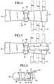
- FIGS. 4-6A method for applying the wound dressing to a body member is exemplified in FIGS. 4-6.
- FIG. 4shows a first step wherein the casing 10 is placed along a substantially flat surface in an extended configuration so that the filler material 17 is evenly distributed in the casing 10.
- FIG. 5shows the next step wherein a body member 60 is positioned onto longitudinal portion 24.
- FIG. 6shows the following step wherein the longitudinal portion 24' is folded to enclose the body member 60. Also shown is lateral portion 26 which is tucked under longitudinal portion 24' to also enclose the body member 60. Although not shown, it follows that lateral portion 26' is also tucked under the folded longitudinal portion 24'.
- the straps 18are wrapped around longitudinal portions 24, 24' to thereby secure the casing 10 to the body member 60.
- the next stepis also shown in FIG.6 which is to connect a vacuum device 20 to the valve 16 via a tube 22.
- Vacuum device 20is used to perform the step of evacuating air from the interior of the casing 10.
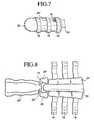
- FIG. 7shows a rigid casing 10 after air has been evacuated from the interior of the casing 10 and the filler material 17 has interengaged.
- the casing 10conforms to the shape fo the body member 60.
- FIG. 8shows the rigid casing 10 opened for inspection of the body member 60 whereby the straps 18 are unsecured and longitudinal portion 24' and lateral portions 26, 26' are folded away from the body member 60.
Landscapes
- Health & Medical Sciences (AREA)
- Animal Behavior & Ethology (AREA)
- Public Health (AREA)
- Engineering & Computer Science (AREA)
- Biomedical Technology (AREA)
- Heart & Thoracic Surgery (AREA)
- Vascular Medicine (AREA)
- Life Sciences & Earth Sciences (AREA)
- General Health & Medical Sciences (AREA)
- Veterinary Medicine (AREA)
- Orthopedic Medicine & Surgery (AREA)
- Nursing (AREA)
- Materials For Medical Uses (AREA)
- Orthopedics, Nursing, And Contraception (AREA)
- Surgical Instruments (AREA)
- Pharmaceuticals Containing Other Organic And Inorganic Compounds (AREA)
- Preparation Of Compounds By Using Micro-Organisms (AREA)
- Transition And Organic Metals Composition Catalysts For Addition Polymerization (AREA)
Abstract
Description
- The present invention pertains to a wound dressing, and more particularly to a rigid dressing for a residual limb immediately after surgical amputation of a limb.
- A wound dressing according to the preamble of claim 1 is known from
DE-U-9 408 537 . - Postoperative treatment of a residual limb after surgical amputation is conducted to ensure primary wound healing and pain control, reduce edema and assist in proper residual limb formation. Conventional postoperative treatment involves soft dressings of sterile gauze and padding followed by a compressive bandage of elastic wrap. These dressings suffer from the disadvantages in that the elastic wrap can generate high pressure on the residual limb and the dressing is cumbersome to remove when inspection of the wound is required.
- An alternative technique is to provide a rigid dressing wherein a nonremovable rigid plaster dressing is applied to the residual limb immediately after limb removal. Although the plaster dressing immobilizes the residual limb, it suffers from several significant disadvantages. Significant disadvantages to this postoperative dressing include the fact that it requires substantial time and skill to apply the plaster dressing. Another disadvantage is that inspection of the residual limb cannot be conducted without breaking and removing the plaster casting from the limb.
- The present invention overcomes the disadvantages of the prior art by providing a rigid wound dressing which is easily configured to enclose a residual limb immediately after surgical amputation while firmly securing the residual limb and permitting easy inspection of the residual limb without destruction of the dressing.
- According to one embodiment of the present invention, there is provided a sealed casing containing an compactable filler material disposed in the interior thereof, with the casing formed of a flexible, air impermeable material that is configured and dimensioned to accommodate a body member. The invention includes an appropriate arrangement permitting communication with the interior of the casing for evacuating air therefrom, whereupon the filler material interengages, in the aggregate, to form a rigid structure conforming to the body member. The sealed casing is divided into portions which are connected to one another but which can be flexed at predetermined points or areas relative to a central portion of the wound dressing after interengagement of the filler material. A pad is connected to the central portion to accommodate a distal end of a body member.
- Significant aspects and features of the present invention include a wound dressing capable of being formed into a rigid structure which enables for ease of application to and inspection of the body member. Particularly, the flexible nature and inherent shape of the casing permit portions of the rigid dressing to be flexed and therefore removed from the body member for inspection of the body member without destruction of the dressing.
- Another significant aspect and feature of the present invention is a wound dressing which provides for rigid securement of a body member which is easily and quickly performed while providing comfort and safety to the body member.
- Although described in the context of securing a residual limb immediately after surgical amputation of a limb, the present invention is not intended to be limited to the securement of residual limbs. Instead, the present invention is directed to any application where securement and inspection of a body member is necessitated in a simple and quick fashion.
FIG. 1 is a plan view of the sealed casing of the present invention.FIG. 1A is a cross-sectional view taken along line I-I inFIG. 1 .FIG. 2 is a plan view showing the interior of the sealed casing.FIG. 3 is a perspective view showing the sealed casing.FIG. 4 is a perspective view showing the wound dressing in an extended configuration.FIG. 5 is a perspective view showing a body member positioned along the wound dressing.FIG. 6 is a perspective view showing the wound dressing connected to a vacuum device and folded over portions of the body member prior to evacuation of air from the interior of the sealed casing.FIG. 7 is a perspective view showing the wound dressing after evacuation of air from the interior of the sealed casing.FIG. 8 is a perspective view showing the wound dressing opened for inspection of the body member.FIG. 1 illustrates a plan view of a sealedcasing 10 made of a flexible, air impermeable sheet material such as a polymer coated textile or polymer film and defining aninterior volume 11. Thecasing 10 may be formed of twoadjoining sheets FIG. 1a , and is divided into opposing elongatedlongitudinal portions lateral portions central portion 28 positioned between thelongitudinal portions lateral portions valve 16 is positioned along one of thelongitudinal portions valve 16.- Disposed in the interior of the
casing 10 is afiller material 17 that interengages, in the aggregate, to form thecasing 10 into a rigid structure conforming to a body member when air is evacuated from the sealedcasing 10 via thevalve 16. The filler material 17 (FIG. 1 a) includes particles within a predetermined size range which is compressible or incompressible when compacted. The particles may include beads, grains, powder or organic material that can be arranged to interengage upon evacuation of air from the sealed vacuum. Specific types offiller material 17 may include thermoplastic and thermoset materials, both foam and solid, and sand. FIG. 2 illustrates the interior of thecasing 10 without thefiller material 17 and shows thedivision 12 of thelongitudinal portions lateral portions central portion 28. Thedivision 12 may be a crease formed by thecasing 10 or a webbing separating the portions of thecasing 10. In effect, thedivision 12 can consist of any arrangement that permits thecasing 10 to be divided into portions which are connected to one another but can be flexed around acentral portion 28 both before and after interengagement of thefiller material 17.- The
casing 10 includes apad 14 positioned at thecentral portion 28 and is either secured onto or integrated into thecasing 10. Thepad 14 is configured and dimensioned to accommodate the distal end of a body member. Thepad 14 can include hook and loop fasteners or other fastening elements (not shown) disposed on one side thereof that correspond to hook and loop fasteners or fastening elements (not shown) positioned on thecentral portion 28 of thecasing 10 so that thepad 14 can be removed and replaced if necessary. FIG. 3 is a perspective view of thecasing 10 withstraps 18 connected tolongitudinal portion 24. Thestraps 18 include connection elements (not shown) disposed at the ends thereof such as hook and loop patches, buckles or snap elements which connect to opposing ends ofrespective straps 18.- While the illustrated shape of the
casing 10 is not to be construed as limiting of the present invention, the gist of the present invention is a sealed casing containing afiller material 17 that is configured and dimensioned to easily enclose a body member. For example, thecasing 10 may comprise of the shape of a circle or a rectangle that include foldable portions to enclose a body member. - A method for applying the wound dressing to a body member is exemplified in
FIGS. 4-6. FIG. 4 shows a first step wherein thecasing 10 is placed along a substantially flat surface in an extended configuration so that thefiller material 17 is evenly distributed in thecasing 10.FIG. 5 shows the next step wherein abody member 60 is positioned ontolongitudinal portion 24.FIG. 6 shows the following step wherein thelongitudinal portion 24' is folded to enclose thebody member 60. Also shown islateral portion 26 which is tucked underlongitudinal portion 24' to also enclose thebody member 60. Although not shown, it follows thatlateral portion 26' is also tucked under the foldedlongitudinal portion 24'. Thestraps 18 are wrapped aroundlongitudinal portions casing 10 to thebody member 60. - The next step is also shown in
FIG.6 which is to connect avacuum device 20 to thevalve 16 via atube 22.Vacuum device 20 is used to perform the step of evacuating air from the interior of thecasing 10. FIG. 7 shows arigid casing 10 after air has been evacuated from the interior of thecasing 10 and thefiller material 17 has interengaged. Thecasing 10 conforms to the shape fo thebody member 60.FIG. 8 shows therigid casing 10 opened for inspection of thebody member 60 whereby thestraps 18 are unsecured andlongitudinal portion 24' andlateral portions body member 60.- The specific embodiments of the invention described herein are intended to be illustrative only and various modifications thereto may be envisioned and implemented by a person skilled in the art without departing from the spirit and scope of the invention which is defined in the claims that follow.
Claims (7)
- A wound dressing for a body member, comprising:a sealed casing (10) formed of a flexible, air impermeable material configured and dimensioned to accommodate and enclose a body member;an compactable filler material (11) disposed in the interior of said casing; anda valve (16) communicating with the interior of the casing (10) for evacuating air therefrom, whereupon the filler material (11) interengages, in the aggregate, to form a rigid structure in combination with the casing conforming to a body member,wherein the casing (10) includes opposed first and second elongated longitudinal portions (24,24') each having first and second ends,characterised by opposed first and second central lateral portions (26,26') each having first and second ends, a central portion (28) located between said longitudinal portions and said lateral portions and a division (12) of the longitudinal portions (24,24') from the central lateral portions (26,26') and the central portion (28), the division permitting the casing (10) to be divided into portions connected to one another but being flexible around the central portion (28), no as to fold said longitudinal portions and lateral portions (24,24',26,26') near said central portion (28) and conform to a body member in the folded configuration.
- The wound dressing according to claim 1, further comprising a pad (14) connected to said central portion (28), and configured and dimensioned to accommodate a distal end of a body member.
- The wound dressing according to claim 1 or 2, further comprising at least one strap (18) connected to one of said longitudinal portions (24,24') and extending lateral relative thereto, said strap having connection elements positioned at the ends thereof configured to connect to one another.
- The wound dressing according to any of claims 1 to 3, wherein the filler material (11) is selected from the group consisting of polymer beads, polymer powder and sand.
- The wound dressing according to claim any of claims 1 to 4, wherein the longitudinal portions (24,24') are substantially greater in length than the lateral portions (26,26').
- A method for applying the wound dressing of any of claims 1 to 5 to a body member, comprising the steps of:placing the wound dressing along a substantially flat surface in an extended configuration wherein the longitudinal, lateral and central portions (24,24',26,26',28) extend along said flat surface to thereby evenly distribute the filler material (11) disposed in the casing (10);positioning the body member onto a first one of the longitudinal portions (24,24');folding the lateral portions (26,26') towards the body member and central portion (11);folding a second one of the longitudinal portions (24,24') over the first longitudinal portion;connecting a vacuum device to the valve (16); andevacuating air from the interior of the casing (10) while maintaining the body member in a predetermined position to cause the filler material (11) to interengage to form a rigid structure conforming to the body member.
- The method according to claim 6 along with claim 3, further comprising the steps of wrapping the at least one strap (18) around the longitudinal portions (24,24') and connecting the connection elements to one another to secure the wound dressing to the body member.
Applications Claiming Priority (3)
| Application Number | Priority Date | Filing Date | Title |
|---|---|---|---|
| US41755602P | 2002-10-11 | 2002-10-11 | |
| US417556P | 2002-10-11 | ||
| PCT/US2003/029121WO2004032977A2 (en) | 2002-10-11 | 2003-10-10 | Rigid dressing |
Publications (3)
| Publication Number | Publication Date |
|---|---|
| EP1555975A2 EP1555975A2 (en) | 2005-07-27 |
| EP1555975A4 EP1555975A4 (en) | 2007-04-04 |
| EP1555975B1true EP1555975B1 (en) | 2008-08-06 |
Family
ID=32094038
Family Applications (1)
| Application Number | Title | Priority Date | Filing Date |
|---|---|---|---|
| EP03759265AExpired - LifetimeEP1555975B1 (en) | 2002-10-11 | 2003-10-10 | Rigid dressing |
Country Status (9)
| Country | Link |
|---|---|
| US (1) | US7094212B2 (en) |
| EP (1) | EP1555975B1 (en) |
| JP (1) | JP2006501941A (en) |
| CN (1) | CN1319497C (en) |
| AT (1) | ATE403408T1 (en) |
| AU (1) | AU2003274996A1 (en) |
| CA (1) | CA2500622C (en) |
| DE (1) | DE60322731D1 (en) |
| WO (1) | WO2004032977A2 (en) |
Families Citing this family (68)
| Publication number | Priority date | Publication date | Assignee | Title |
|---|---|---|---|---|
| US20040064195A1 (en) | 2002-07-15 | 2004-04-01 | Hugh Herr | Variable-mechanical-impedance artificial legs |
| US7846141B2 (en) | 2002-09-03 | 2010-12-07 | Bluesky Medical Group Incorporated | Reduced pressure treatment system |
| GB0224986D0 (en) | 2002-10-28 | 2002-12-04 | Smith & Nephew | Apparatus |
| WO2004075779A2 (en)* | 2003-02-27 | 2004-09-10 | Hanger Orthopedic Group Inc. | Post-operative dressing for below knee amputees |
| US8075633B2 (en) | 2003-09-25 | 2011-12-13 | Massachusetts Institute Of Technology | Active ankle foot orthosis |
| GB0323881D0 (en)* | 2003-10-11 | 2003-11-12 | Graham Neil W | Novel occlusive dressing |
| US8062272B2 (en) | 2004-05-21 | 2011-11-22 | Bluesky Medical Group Incorporated | Flexible reduced pressure treatment appliance |
| US10058642B2 (en) | 2004-04-05 | 2018-08-28 | Bluesky Medical Group Incorporated | Reduced pressure treatment system |
| US7909805B2 (en) | 2004-04-05 | 2011-03-22 | Bluesky Medical Group Incorporated | Flexible reduced pressure treatment appliance |
| GB0409446D0 (en) | 2004-04-28 | 2004-06-02 | Smith & Nephew | Apparatus |
| US10307272B2 (en) | 2005-03-31 | 2019-06-04 | Massachusetts Institute Of Technology | Method for using a model-based controller for a robotic leg |
| US20070123997A1 (en) | 2005-03-31 | 2007-05-31 | Massachusetts Institute Of Technology | Exoskeletons for running and walking |
| US8864846B2 (en) | 2005-03-31 | 2014-10-21 | Massachusetts Institute Of Technology | Model-based neuromechanical controller for a robotic leg |
| US20070043449A1 (en) | 2005-03-31 | 2007-02-22 | Massachusetts Institute Of Technology | Artificial ankle-foot system with spring, variable-damping, and series-elastic actuator components |
| US8500823B2 (en) | 2005-03-31 | 2013-08-06 | Massachusetts Institute Of Technology | Powered artificial knee with agonist-antagonist actuation |
| US20060249315A1 (en) | 2005-03-31 | 2006-11-09 | Massachusetts Institute Of Technology | Artificial human limbs and joints employing actuators, springs, and variable-damper elements |
| US11278433B2 (en) | 2005-03-31 | 2022-03-22 | Massachusetts Institute Of Technology | Powered ankle-foot prosthesis |
| US20070162152A1 (en) | 2005-03-31 | 2007-07-12 | Massachusetts Institute Of Technology | Artificial joints using agonist-antagonist actuators |
| US10080672B2 (en) | 2005-03-31 | 2018-09-25 | Bionx Medical Technologies, Inc. | Hybrid terrain-adaptive lower-extremity systems |
| US8512415B2 (en) | 2005-03-31 | 2013-08-20 | Massachusetts Institute Of Technology | Powered ankle-foot prothesis |
| US7905852B2 (en)* | 2006-05-16 | 2011-03-15 | Barbara Jennings-Spring | Skin-contacting-adhesive free dressing |
| US7645252B2 (en)* | 2006-05-16 | 2010-01-12 | Barbara Brooke Jennings-Spring | Body or plant part dressing |
| US7878994B2 (en)* | 2007-01-29 | 2011-02-01 | Joseph Michael Swope | Cast for immobilizing and heating or cooling a body part |
| US10842653B2 (en) | 2007-09-19 | 2020-11-24 | Ability Dynamics, Llc | Vacuum system for a prosthetic foot |
| JP2009112380A (en)* | 2007-11-02 | 2009-05-28 | Japan Health Science Foundation | Shape-retaining bag, and prosthesis and body-molding tool using the same |
| WO2009067711A2 (en) | 2007-11-21 | 2009-05-28 | T.J. Smith & Nephew, Limited | Suction device and dressing |
| GB0722820D0 (en) | 2007-11-21 | 2008-01-02 | Smith & Nephew | Vacuum assisted wound dressing |
| ES2715605T3 (en) | 2007-11-21 | 2019-06-05 | Smith & Nephew | Wound dressing |
| US20130096518A1 (en) | 2007-12-06 | 2013-04-18 | Smith & Nephew Plc | Wound filling apparatuses and methods |
| US11253399B2 (en) | 2007-12-06 | 2022-02-22 | Smith & Nephew Plc | Wound filling apparatuses and methods |
| GB0723875D0 (en) | 2007-12-06 | 2008-01-16 | Smith & Nephew | Wound management |
| GB0803564D0 (en) | 2008-02-27 | 2008-04-02 | Smith & Nephew | Fluid collection |
| GB2461048C (en)* | 2008-06-18 | 2012-11-21 | Jake Timothy | Improved wound dressing |
| KR20110074520A (en) | 2008-09-04 | 2011-06-30 | 아이워크, 아이엔씨. | Hybrid Terrain-Adaptive Prosthetic Systems |
| US20110082566A1 (en) | 2008-09-04 | 2011-04-07 | Herr Hugh M | Implementing a stand-up sequence using a lower-extremity prosthesis or orthosis |
| US8540654B2 (en)* | 2009-03-30 | 2013-09-24 | Reginald J. Davis | Therapeutic massage sock |
| US8663132B2 (en)* | 2009-04-14 | 2014-03-04 | Kci Licensing, Inc. | Reduced-pressure treatment systems and methods employing a variable cover |
| CN102892388A (en) | 2010-04-05 | 2013-01-23 | Iwalk股份有限公司 | Controlling torque in a prosthesis or orthosis |
| US9061095B2 (en) | 2010-04-27 | 2015-06-23 | Smith & Nephew Plc | Wound dressing and method of use |
| GB201011173D0 (en) | 2010-07-02 | 2010-08-18 | Smith & Nephew | Provision of wound filler |
| JP4669575B1 (en)* | 2010-08-24 | 2011-04-13 | キヨタ株式会社 | Footrest cover |
| US8795385B2 (en) | 2010-10-22 | 2014-08-05 | Ossur Hf | Adjustable socket system |
| GB201020005D0 (en) | 2010-11-25 | 2011-01-12 | Smith & Nephew | Composition 1-1 |
| CA2819032C (en) | 2010-11-25 | 2020-06-23 | Smith & Nephew Plc | Composition i-ii and products and uses thereof |
| WO2012096956A1 (en) | 2011-01-10 | 2012-07-19 | Iwalk, Inc. | Powered joint orthosis |
| US20120259430A1 (en) | 2011-01-12 | 2012-10-11 | Zhixiu Han | Controlling powered human augmentation devices |
| US9687377B2 (en) | 2011-01-21 | 2017-06-27 | Bionx Medical Technologies, Inc. | Terrain adaptive powered joint orthosis |
| WO2012125562A1 (en) | 2011-03-11 | 2012-09-20 | Iwalk, Inc. | Biomimetic joint actuators |
| WO2013067407A1 (en) | 2011-11-02 | 2013-05-10 | Iwalk, Inc. | Biomimetic transfemoral prosthesis |
| US20150159066A1 (en) | 2011-11-25 | 2015-06-11 | Smith & Nephew Plc | Composition, apparatus, kit and method and uses thereof |
| US9032635B2 (en) | 2011-12-15 | 2015-05-19 | Massachusetts Institute Of Technology | Physiological measurement device or wearable device interface simulator and method of use |
| US9221177B2 (en) | 2012-04-18 | 2015-12-29 | Massachusetts Institute Of Technology | Neuromuscular model-based sensing and control paradigm for a robotic leg |
| WO2013188510A2 (en) | 2012-06-12 | 2013-12-19 | Iwalk, Inc. | Prosthetic, orthotic or exoskeleton device |
| WO2014005071A1 (en) | 2012-06-28 | 2014-01-03 | Ossur Hf | Adjustable prosthetic limb system |
| US20160120706A1 (en) | 2013-03-15 | 2016-05-05 | Smith & Nephew Plc | Wound dressing sealant and use thereof |
| EP2968647B1 (en) | 2013-03-15 | 2022-06-29 | Smith & Nephew plc | Wound dressing sealant and use thereof |
| CN104302254B (en)* | 2013-03-15 | 2018-01-23 | 泰克斯提亚创新方案有限公司 | Elements with variable stiffness controlled by negative pressure |
| US20170095365A1 (en)* | 2014-03-27 | 2017-04-06 | Koninklijke Philips N.V. | Vacuum splint with radio frequency coil for magnetic resonance imaging |
| WO2015179332A1 (en) | 2014-05-19 | 2015-11-26 | Ossur Hf | Adjustable prosthetic device |
| US9504598B2 (en)* | 2014-07-10 | 2016-11-29 | Advance Kites S.R.L. | Adaptable protective device |
| EP2965727B1 (en)* | 2014-07-10 | 2018-12-26 | Advance Kites S.r.l. | Adaptable protective device |
| EP3294230B1 (en) | 2015-05-13 | 2019-04-17 | Ossur Iceland EHF | Adjustable socket system |
| CA3021581A1 (en)* | 2016-04-19 | 2017-10-26 | Lifecell Corporation | Stress relieving device |
| US10940028B2 (en) | 2017-02-06 | 2021-03-09 | Ossur Iceland Ehf | Adjustable socket system |
| US11419740B2 (en) | 2017-02-06 | 2022-08-23 | Ossur Iceland Ehf | Adjustable socket system |
| EP3576682B1 (en) | 2017-02-06 | 2021-08-04 | Össur Iceland EHF | Adjustable socket system |
| CN106901906B (en)* | 2017-03-04 | 2020-08-14 | 鹤壁市人民医院 | Medical bone-knitting robot |
| EP4208130A1 (en) | 2020-09-04 | 2023-07-12 | Ossur Iceland Ehf | Interchangeable distal end for a prosthetic socket system |
Family Cites Families (9)
| Publication number | Priority date | Publication date | Assignee | Title |
|---|---|---|---|---|
| US3186405A (en)* | 1962-11-13 | 1965-06-01 | Robert E Bailey | Inflatable splint |
| US3212497A (en)* | 1963-04-09 | 1965-10-19 | Joseph A Kaplan & Sons Inc | Moldable temporary splint |
| GB1422966A (en)* | 1973-06-17 | 1976-01-28 | Schetrumpf J R | Mouldable means |
| US4157713A (en)* | 1977-05-11 | 1979-06-12 | Clarey Michael T | Air-pressure splint |
| US5108455A (en)* | 1988-10-21 | 1992-04-28 | Telikicherla Madan M | Lower limb prosthesis having removable rigid amputation stump dressing |
| US5190033A (en)* | 1991-06-10 | 1993-03-02 | Johnson Linda J | Ice peas cold/hot therapeutic pack |
| DE69314313T2 (en)* | 1992-08-10 | 1998-04-23 | Okanagan House Inc | THERMAL BANDAGE |
| DE9408537U1 (en)* | 1994-05-25 | 1994-09-01 | Habermeyer, Peter, Prof. Dr., 70184 Stuttgart | Evacuable pillow with fillers as an insert in a device for enclosing extremities |
| US5578022A (en)* | 1995-04-12 | 1996-11-26 | Scherson; Daniel A. | Oxygen producing bandage and method |
- 2003
- 2003-10-09USUS10/681,134patent/US7094212B2/ennot_activeExpired - Lifetime
- 2003-10-10EPEP03759265Apatent/EP1555975B1/ennot_activeExpired - Lifetime
- 2003-10-10DEDE60322731Tpatent/DE60322731D1/ennot_activeExpired - Lifetime
- 2003-10-10ATAT03759265Tpatent/ATE403408T1/ennot_activeIP Right Cessation
- 2003-10-10WOPCT/US2003/029121patent/WO2004032977A2/enactiveApplication Filing
- 2003-10-10CACA2500622Apatent/CA2500622C/ennot_activeExpired - Fee Related
- 2003-10-10CNCNB2003801011094Apatent/CN1319497C/ennot_activeExpired - Fee Related
- 2003-10-10AUAU2003274996Apatent/AU2003274996A1/ennot_activeAbandoned
- 2003-10-10JPJP2004543306Apatent/JP2006501941A/enactivePending
Also Published As
| Publication number | Publication date |
|---|---|
| AU2003274996A1 (en) | 2004-05-04 |
| CN1319497C (en) | 2007-06-06 |
| AU2003274996A8 (en) | 2004-05-04 |
| JP2006501941A (en) | 2006-01-19 |
| WO2004032977A3 (en) | 2004-08-05 |
| US7094212B2 (en) | 2006-08-22 |
| ATE403408T1 (en) | 2008-08-15 |
| EP1555975A4 (en) | 2007-04-04 |
| CA2500622A1 (en) | 2004-04-22 |
| CA2500622C (en) | 2011-02-08 |
| WO2004032977A2 (en) | 2004-04-22 |
| US20040073152A1 (en) | 2004-04-15 |
| DE60322731D1 (en) | 2008-09-18 |
| EP1555975A2 (en) | 2005-07-27 |
| CN1703180A (en) | 2005-11-30 |
Similar Documents
| Publication | Publication Date | Title |
|---|---|---|
| EP1555975B1 (en) | Rigid dressing | |
| EP1670400B1 (en) | Casting system | |
| EP1904001B1 (en) | Splint or support with quick location technique | |
| MX2012007772A (en) | Fitting element with controlled stiffness. | |
| US7677249B2 (en) | Device and method for providing a lateralization effect | |
| US3867930A (en) | Traction band with integral fasteners | |
| US8641731B2 (en) | Emergency snake bite treatment devices, medical kits and related methods | |
| GB2490709A (en) | Self-contained splint using frangible fluid pouch | |
| US20040147859A1 (en) | Orthopedic cast construction | |
| CN116392307B (en) | An emergency fixation device for pelvic injury | |
| US2834341A (en) | Splint | |
| EP1635748A1 (en) | Pad with aircell for an orthopedic brace | |
| CA3046724C (en) | Self-curing orthopedic splint and method for applying same | |
| US10463543B2 (en) | Self-curing orthopedic splint and method for applying same | |
| JPH0680420U (en) | Joint supporter | |
| WO2019144162A1 (en) | Self-curing orthopedic splint and method for applying same | |
| WO2002067832A1 (en) | Orthopedic cast construction | |
| KR20230110385A (en) | Emergency splint | |
| CN115969625A (en) | Compressible protective dressing assembly for thoracoabdominal open wounds | |
| JPH1085252A (en) | Skin protection coating | |
| JP2003010216A (en) | Emergency prosthesis and emergency prosthesis set | |
| GB2387543A (en) | Plaster cast band with elastic sections | |
| UA50532A (en) | Cover for cramers ladder splint |
Legal Events
| Date | Code | Title | Description |
|---|---|---|---|
| PUAI | Public reference made under article 153(3) epc to a published international application that has entered the european phase | Free format text:ORIGINAL CODE: 0009012 | |
| 17P | Request for examination filed | Effective date:20050329 | |
| AK | Designated contracting states | Kind code of ref document:A2 Designated state(s):AT BE BG CH CY CZ DE DK EE ES FI FR GB GR HU IE IT LI LU MC NL PT RO SE SI SK TR | |
| AX | Request for extension of the european patent | Extension state:AL LT LV MK | |
| DAX | Request for extension of the european patent (deleted) | ||
| A4 | Supplementary search report drawn up and despatched | Effective date:20070305 | |
| RIC1 | Information provided on ipc code assigned before grant | Ipc:A61F 13/04 20060101AFI20070227BHEP | |
| GRAP | Despatch of communication of intention to grant a patent | Free format text:ORIGINAL CODE: EPIDOSNIGR1 | |
| GRAS | Grant fee paid | Free format text:ORIGINAL CODE: EPIDOSNIGR3 | |
| GRAA | (expected) grant | Free format text:ORIGINAL CODE: 0009210 | |
| AK | Designated contracting states | Kind code of ref document:B1 Designated state(s):AT BE BG CH CY CZ DE DK EE ES FI FR GB GR HU IE IT LI LU MC NL PT RO SE SI SK TR | |
| REG | Reference to a national code | Ref country code:GB Ref legal event code:FG4D | |
| REG | Reference to a national code | Ref country code:CH Ref legal event code:EP | |
| REG | Reference to a national code | Ref country code:IE Ref legal event code:FG4D | |
| REF | Corresponds to: | Ref document number:60322731 Country of ref document:DE Date of ref document:20080918 Kind code of ref document:P | |
| REG | Reference to a national code | Ref country code:SE Ref legal event code:TRGR | |
| PG25 | Lapsed in a contracting state [announced via postgrant information from national office to epo] | Ref country code:ES Free format text:LAPSE BECAUSE OF FAILURE TO SUBMIT A TRANSLATION OF THE DESCRIPTION OR TO PAY THE FEE WITHIN THE PRESCRIBED TIME-LIMIT Effective date:20081117 Ref country code:NL Free format text:LAPSE BECAUSE OF FAILURE TO SUBMIT A TRANSLATION OF THE DESCRIPTION OR TO PAY THE FEE WITHIN THE PRESCRIBED TIME-LIMIT Effective date:20080806 | |
| PG25 | Lapsed in a contracting state [announced via postgrant information from national office to epo] | Ref country code:SI Free format text:LAPSE BECAUSE OF FAILURE TO SUBMIT A TRANSLATION OF THE DESCRIPTION OR TO PAY THE FEE WITHIN THE PRESCRIBED TIME-LIMIT Effective date:20080806 Ref country code:AT Free format text:LAPSE BECAUSE OF FAILURE TO SUBMIT A TRANSLATION OF THE DESCRIPTION OR TO PAY THE FEE WITHIN THE PRESCRIBED TIME-LIMIT Effective date:20080806 Ref country code:FI Free format text:LAPSE BECAUSE OF FAILURE TO SUBMIT A TRANSLATION OF THE DESCRIPTION OR TO PAY THE FEE WITHIN THE PRESCRIBED TIME-LIMIT Effective date:20080806 | |
| PG25 | Lapsed in a contracting state [announced via postgrant information from national office to epo] | Ref country code:BE Free format text:LAPSE BECAUSE OF FAILURE TO SUBMIT A TRANSLATION OF THE DESCRIPTION OR TO PAY THE FEE WITHIN THE PRESCRIBED TIME-LIMIT Effective date:20080806 | |
| PG25 | Lapsed in a contracting state [announced via postgrant information from national office to epo] | Ref country code:BG Free format text:LAPSE BECAUSE OF FAILURE TO SUBMIT A TRANSLATION OF THE DESCRIPTION OR TO PAY THE FEE WITHIN THE PRESCRIBED TIME-LIMIT Effective date:20081106 Ref country code:DK Free format text:LAPSE BECAUSE OF FAILURE TO SUBMIT A TRANSLATION OF THE DESCRIPTION OR TO PAY THE FEE WITHIN THE PRESCRIBED TIME-LIMIT Effective date:20080806 | |
| PG25 | Lapsed in a contracting state [announced via postgrant information from national office to epo] | Ref country code:SK Free format text:LAPSE BECAUSE OF FAILURE TO SUBMIT A TRANSLATION OF THE DESCRIPTION OR TO PAY THE FEE WITHIN THE PRESCRIBED TIME-LIMIT Effective date:20080806 Ref country code:PT Free format text:LAPSE BECAUSE OF FAILURE TO SUBMIT A TRANSLATION OF THE DESCRIPTION OR TO PAY THE FEE WITHIN THE PRESCRIBED TIME-LIMIT Effective date:20090106 Ref country code:RO Free format text:LAPSE BECAUSE OF FAILURE TO SUBMIT A TRANSLATION OF THE DESCRIPTION OR TO PAY THE FEE WITHIN THE PRESCRIBED TIME-LIMIT Effective date:20080806 Ref country code:MC Free format text:LAPSE BECAUSE OF NON-PAYMENT OF DUE FEES Effective date:20081031 Ref country code:CZ Free format text:LAPSE BECAUSE OF FAILURE TO SUBMIT A TRANSLATION OF THE DESCRIPTION OR TO PAY THE FEE WITHIN THE PRESCRIBED TIME-LIMIT Effective date:20080806 | |
| REG | Reference to a national code | Ref country code:CH Ref legal event code:PL | |
| PLBE | No opposition filed within time limit | Free format text:ORIGINAL CODE: 0009261 | |
| STAA | Information on the status of an ep patent application or granted ep patent | Free format text:STATUS: NO OPPOSITION FILED WITHIN TIME LIMIT | |
| 26N | No opposition filed | Effective date:20090507 | |
| PG25 | Lapsed in a contracting state [announced via postgrant information from national office to epo] | Ref country code:EE Free format text:LAPSE BECAUSE OF FAILURE TO SUBMIT A TRANSLATION OF THE DESCRIPTION OR TO PAY THE FEE WITHIN THE PRESCRIBED TIME-LIMIT Effective date:20080806 | |
| PG25 | Lapsed in a contracting state [announced via postgrant information from national office to epo] | Ref country code:IT Free format text:LAPSE BECAUSE OF FAILURE TO SUBMIT A TRANSLATION OF THE DESCRIPTION OR TO PAY THE FEE WITHIN THE PRESCRIBED TIME-LIMIT Effective date:20080806 | |
| PG25 | Lapsed in a contracting state [announced via postgrant information from national office to epo] | Ref country code:IE Free format text:LAPSE BECAUSE OF NON-PAYMENT OF DUE FEES Effective date:20081010 Ref country code:LI Free format text:LAPSE BECAUSE OF NON-PAYMENT OF DUE FEES Effective date:20081031 Ref country code:CH Free format text:LAPSE BECAUSE OF NON-PAYMENT OF DUE FEES Effective date:20081031 | |
| PG25 | Lapsed in a contracting state [announced via postgrant information from national office to epo] | Ref country code:CY Free format text:LAPSE BECAUSE OF FAILURE TO SUBMIT A TRANSLATION OF THE DESCRIPTION OR TO PAY THE FEE WITHIN THE PRESCRIBED TIME-LIMIT Effective date:20080806 Ref country code:HU Free format text:LAPSE BECAUSE OF FAILURE TO SUBMIT A TRANSLATION OF THE DESCRIPTION OR TO PAY THE FEE WITHIN THE PRESCRIBED TIME-LIMIT Effective date:20090207 Ref country code:LU Free format text:LAPSE BECAUSE OF NON-PAYMENT OF DUE FEES Effective date:20081010 | |
| PG25 | Lapsed in a contracting state [announced via postgrant information from national office to epo] | Ref country code:TR Free format text:LAPSE BECAUSE OF FAILURE TO SUBMIT A TRANSLATION OF THE DESCRIPTION OR TO PAY THE FEE WITHIN THE PRESCRIBED TIME-LIMIT Effective date:20080806 | |
| PG25 | Lapsed in a contracting state [announced via postgrant information from national office to epo] | Ref country code:GR Free format text:LAPSE BECAUSE OF FAILURE TO SUBMIT A TRANSLATION OF THE DESCRIPTION OR TO PAY THE FEE WITHIN THE PRESCRIBED TIME-LIMIT Effective date:20081107 | |
| REG | Reference to a national code | Ref country code:FR Ref legal event code:PLFP Year of fee payment:14 | |
| REG | Reference to a national code | Ref country code:DE Ref legal event code:R082 Ref document number:60322731 Country of ref document:DE Representative=s name:KLUNKER IP PATENTANWAELTE PARTG MBB, DE | |
| REG | Reference to a national code | Ref country code:FR Ref legal event code:PLFP Year of fee payment:15 | |
| PGFP | Annual fee paid to national office [announced via postgrant information from national office to epo] | Ref country code:FR Payment date:20170918 Year of fee payment:15 | |
| PGFP | Annual fee paid to national office [announced via postgrant information from national office to epo] | Ref country code:SE Payment date:20171011 Year of fee payment:15 Ref country code:GB Payment date:20171004 Year of fee payment:15 | |
| PGFP | Annual fee paid to national office [announced via postgrant information from national office to epo] | Ref country code:DE Payment date:20180925 Year of fee payment:16 | |
| REG | Reference to a national code | Ref country code:SE Ref legal event code:EUG | |
| GBPC | Gb: european patent ceased through non-payment of renewal fee | Effective date:20181010 | |
| PG25 | Lapsed in a contracting state [announced via postgrant information from national office to epo] | Ref country code:SE Free format text:LAPSE BECAUSE OF NON-PAYMENT OF DUE FEES Effective date:20181011 | |
| PG25 | Lapsed in a contracting state [announced via postgrant information from national office to epo] | Ref country code:FR Free format text:LAPSE BECAUSE OF NON-PAYMENT OF DUE FEES Effective date:20181031 | |
| PG25 | Lapsed in a contracting state [announced via postgrant information from national office to epo] | Ref country code:GB Free format text:LAPSE BECAUSE OF NON-PAYMENT OF DUE FEES Effective date:20181010 | |
| REG | Reference to a national code | Ref country code:DE Ref legal event code:R119 Ref document number:60322731 Country of ref document:DE | |
| PG25 | Lapsed in a contracting state [announced via postgrant information from national office to epo] | Ref country code:DE Free format text:LAPSE BECAUSE OF NON-PAYMENT OF DUE FEES Effective date:20200501 |