EP1554972A1 - Endoscope device - Google Patents
Endoscope deviceDownload PDFInfo
- Publication number
- EP1554972A1 EP1554972A1EP03758757AEP03758757AEP1554972A1EP 1554972 A1EP1554972 A1EP 1554972A1EP 03758757 AEP03758757 AEP 03758757AEP 03758757 AEP03758757 AEP 03758757AEP 1554972 A1EP1554972 A1EP 1554972A1
- Authority
- EP
- European Patent Office
- Prior art keywords
- endoscope
- outer diameter
- diameter portion
- section
- diameter
- Prior art date
- Legal status (The legal status is an assumption and is not a legal conclusion. Google has not performed a legal analysis and makes no representation as to the accuracy of the status listed.)
- Granted
Links
Images


Classifications
- A—HUMAN NECESSITIES
- A61—MEDICAL OR VETERINARY SCIENCE; HYGIENE
- A61B—DIAGNOSIS; SURGERY; IDENTIFICATION
- A61B1/00—Instruments for performing medical examinations of the interior of cavities or tubes of the body by visual or photographical inspection, e.g. endoscopes; Illuminating arrangements therefor
- A61B1/00064—Constructional details of the endoscope body
- A61B1/0011—Manufacturing of endoscope parts
- A—HUMAN NECESSITIES
- A61—MEDICAL OR VETERINARY SCIENCE; HYGIENE
- A61B—DIAGNOSIS; SURGERY; IDENTIFICATION
- A61B1/00—Instruments for performing medical examinations of the interior of cavities or tubes of the body by visual or photographical inspection, e.g. endoscopes; Illuminating arrangements therefor
- A61B1/00064—Constructional details of the endoscope body
- A61B1/00071—Insertion part of the endoscope body
- A61B1/00078—Insertion part of the endoscope body with stiffening means
- A—HUMAN NECESSITIES
- A61—MEDICAL OR VETERINARY SCIENCE; HYGIENE
- A61B—DIAGNOSIS; SURGERY; IDENTIFICATION
- A61B1/00—Instruments for performing medical examinations of the interior of cavities or tubes of the body by visual or photographical inspection, e.g. endoscopes; Illuminating arrangements therefor
- A61B1/005—Flexible endoscopes
- A61B1/0051—Flexible endoscopes with controlled bending of insertion part
- A61B1/0055—Constructional details of insertion parts, e.g. vertebral elements
- A—HUMAN NECESSITIES
- A61—MEDICAL OR VETERINARY SCIENCE; HYGIENE
- A61B—DIAGNOSIS; SURGERY; IDENTIFICATION
- A61B1/00—Instruments for performing medical examinations of the interior of cavities or tubes of the body by visual or photographical inspection, e.g. endoscopes; Illuminating arrangements therefor
- A61B1/31—Instruments for performing medical examinations of the interior of cavities or tubes of the body by visual or photographical inspection, e.g. endoscopes; Illuminating arrangements therefor for the rectum, e.g. proctoscopes, sigmoidoscopes, colonoscopes
- H—ELECTRICITY
- H04—ELECTRIC COMMUNICATION TECHNIQUE
- H04N—PICTORIAL COMMUNICATION, e.g. TELEVISION
- H04N7/00—Television systems
- H04N7/18—Closed-circuit television [CCTV] systems, i.e. systems in which the video signal is not broadcast
- H04N7/181—Closed-circuit television [CCTV] systems, i.e. systems in which the video signal is not broadcast for receiving images from a plurality of remote sources
- A—HUMAN NECESSITIES
- A61—MEDICAL OR VETERINARY SCIENCE; HYGIENE
- A61B—DIAGNOSIS; SURGERY; IDENTIFICATION
- A61B1/00—Instruments for performing medical examinations of the interior of cavities or tubes of the body by visual or photographical inspection, e.g. endoscopes; Illuminating arrangements therefor
- A61B1/005—Flexible endoscopes
- A61B1/0051—Flexible endoscopes with controlled bending of insertion part
- A61B1/0052—Constructional details of control elements, e.g. handles
- A—HUMAN NECESSITIES
- A61—MEDICAL OR VETERINARY SCIENCE; HYGIENE
- A61B—DIAGNOSIS; SURGERY; IDENTIFICATION
- A61B1/00—Instruments for performing medical examinations of the interior of cavities or tubes of the body by visual or photographical inspection, e.g. endoscopes; Illuminating arrangements therefor
- A61B1/012—Instruments for performing medical examinations of the interior of cavities or tubes of the body by visual or photographical inspection, e.g. endoscopes; Illuminating arrangements therefor characterised by internal passages or accessories therefor
- A61B1/018—Instruments for performing medical examinations of the interior of cavities or tubes of the body by visual or photographical inspection, e.g. endoscopes; Illuminating arrangements therefor characterised by internal passages or accessories therefor for receiving instruments
- A—HUMAN NECESSITIES
- A61—MEDICAL OR VETERINARY SCIENCE; HYGIENE
- A61B—DIAGNOSIS; SURGERY; IDENTIFICATION
- A61B1/00—Instruments for performing medical examinations of the interior of cavities or tubes of the body by visual or photographical inspection, e.g. endoscopes; Illuminating arrangements therefor
- A61B1/12—Instruments for performing medical examinations of the interior of cavities or tubes of the body by visual or photographical inspection, e.g. endoscopes; Illuminating arrangements therefor with cooling or rinsing arrangements
Definitions
- the present inventionrelates to an endoscope system in which the ease of insertion of an endoscope into the large intestine can be improved.
- the insertion unit of an endoscopeincludes a soft section having flexibility.
- a distal sectionis formed distally to the soft section with a bending section between them.
- An observation window, an illumination window, a treatment instrument passage channel opening, and othersare arranged in a predetermined manner on the distal plane of the distal section.
- the portion of the soft section on the distal side thereofis made more flexible so that it will be more soft and bendable.
- the portion of the soft section on the proximal side thereofis made little flexible so that the ease of insertion thereof will improve.
- Japanese Unexamined Patent Application Publication No. 2001-190494has disclosed the technology of ensuring the flexibility of the portion of a soft section on the distal side thereof and improving the ease of insertion thereof.
- the outer diameter of the soft sectionis gradually increased from the distal end thereof to the proximal end thereof so that the flexibility of the portion of the soft section on the proximal side thereof will be smaller than that of the distal-side portion thereof.
- An object of the present inventionis to provide an endoscope system that does not give a feeling of wrongness to an operator when the operator holds the large-diameter portions of the soft sections of a plurality of endoscopes included in the endoscope system.
- the present inventionprovides an endoscope system comprising: a first endoscope whose soft section includes a small-diameter portion that is a distal portion and a large-diameter portion which is formed proximally to the small-diameter portion and whose outer diameter is larger than that of the small-diameter portion; a second endoscope that shares the same light source unit or video processor with the first endoscope and whose soft section has substantially the same outer diameter over the whole length thereof; and a third endoscope whose soft section has substantially the same outer diameter over the whole length thereof and has an outer diameter substantially identical to or smaller than the outer diameter of the second endoscope.
- the outer diameter of at least the large-diameter portion of the first endoscopeis substantially identical to or smaller than the outer diameter of the soft section of the second endoscope, and is substantially identical to or larger than the outer diameter of the soft section of the third endoscope.
- Fig. 1 to Fig. 7Dshow a first embodiment of the present invention.
- an endoscope 1includes: an insertion unit 2 having a solid-state imaging device such as a CCD incorporated in the distal part thereof; an operating unit 3 coupled to the proximal end of the insertion unit 2 and held and handled by an observer; and a universal cord 4 extended from the operating unit 3.
- a solid-state imaging devicesuch as a CCD incorporated in the distal part thereof
- an operating unit 3coupled to the proximal end of the insertion unit 2 and held and handled by an observer
- a universal cord 4extended from the operating unit 3.
- a connector unit 5is formed at the end of the universal cord 4.
- the connector unit 5includes a light guide connector 6 and a camera connector 7.
- the light guide connector 6 and camera connector 7are coupled to peripheral equipment including a light source unit and a camera control unit.
- the insertion unit 2has, from the distal end thereof, a distal section 8, a bending section 9 that can be freely bent, and a soft section 10 having flexibility.
- the proximal end of the soft section 10is coupled to the operating unit 3.
- an observation window, an illumination window, a treatment instrument passage channel opening, and an aeration/perfusion nozzleare arranged in a predetermined manner on the distal plane of the distal section 8. These are not shown in the drawing.
- the operating unit 3includes an angulation lever 11 used to remotely control bending of the bending section 9, a treatment instrument insertion port 12 through which a treatment instrument such as forceps are inserted, and a plurality of switches 13 used to freeze or expose an image.
- the soft section 10has: a small-diameter portion 10a which is formed on the distal side of the soft section and whose outer diameter is substantially the same over the whole length thereof; a large-diameter portion 10b which is formed on the operator side of the soft section opposite to the small-diameter portion 10a and whose outer diameter is larger than the outer diameter of the small-diameter portion 10a; and a tapered portion 10c that smoothly links the small-diameter portion 10a and large-diameter portion 10b.
- the border between the small-diameter portion 10a and tapered portion 10cis indicated with arrow A
- the border between the tapered portion 10c and large-diameter portion 10bis indicated with arrow B.
- the length from the distal end of the distal section 8 that is the distal part of the insertion unit 2 to the rear end of the small-diameter portion 10a indicated with arrow Amay be 30 cm, 40 cm, or 50 cm, or in other words, varies depending on the purpose of use of the endoscope 1. Normally, an endoscope having the length of 70 cm does not exist. Consequently, the rear end of the small-diameter portion 10a indicated with arrow A is located forward a point that is separated from the distal end of the distal section 8 by 70 cm.
- Fig. 3schematically shows part of the internal structure of the soft section 10.
- a flexible tube 20 that is an armor of the soft section 10comprises, from the internal side thereof, spiral tubes 21a and 21b that wind in mutually opposite directions, a braided tube 22, and a sheathing resin 24.
- the spiral tubes 21a and 21b and braided tube 22have substantially constant inner and outer diameters over the whole lengths thereof.
- the thickness of the sheathing resin 24is varied in order to form the small-diameter portion 10a, large-diameter portion 10b, and tapered portion 10c linking the small-diameter and large-diameter portions.
- two layers of spiral tubesare included as the spiral tubes 21a and 21b.
- the number of layers of spiral tubesmay be one or three or more.
- a method of molding the flexible tube 20is, for example, such that the spiral tubes 21a and 21b and braided tube 22 which are assembled in a predetermined manner are used as a core die to perform extrusion molding so that the sheathing resin 24 will mold to the braided tube 22.
- the small-diameter portion 10a, tapered portion 10c, and large-diameter portion 10bare formed by changing the speed at which the core die is pulled out.
- the speed at which the core die is pulled outis raised in order to form the small-diameter portion 10a, and lowered in order to form the large-diameter portion 10b. While molding proceeds from the stage in which the small-diameter portion 10a is formed to the stage in which the large-diameter portion 10b is formed or vice versa, the pullout speed is changed continuously in order to form the tapered portion 10c.
- the above molding methodemploys dies having the same inner diameter. Therefore, it is hard to form the portions 10a to 10c having precise outer diameters.
- a plurality of tapered grinding stones 23is used to perform centerless grinding on a bar-like flexible tube material 20' manufactured to have a sole outer diameter. If the small-diameter portion 10a and tapered portion 10c are thus formed, the portions 10a to 10c will have precise outer diameters.
- the flexible tube material 20' having the same outer diameter as the large-diameter portion 10bis relatively approached to the axial core of the plurality of tapered grinding stones 23 arranged circumferentially around the flexible tube material 20'.
- the flexible tube material 20'is pressed against the plurality of tapered grinding stones 23.
- the flexible tube material 20'thus has the surface thereof ground in line with the shape defined with the plurality of tapered grinding stones 23. Consequently, the distal part of the flexible tube material 20' has the small-diameter portion 10a and tapered portion 10c formed as shown in Fig. 4C.
- the small-diameter portion 10a, tapered portion 10c, and large-diameter portion 10bcan be formed highly precisely.
- the small-diameter portion 10a, tapered portion 10c, and large-diameter portion 10bmay be formed highly precisely by performing extrusion molding as shown in Fig. 5A to Fig. 5D.
- a flexible tube material 20" having the same outer diameter as the small-diameter portion 10a over the whole length thereof and comprising the spiral tubes 21a and 21b, the braided tube 22, and a first sheathing resin 24ais manufactured by performing extrusion molding.
- the portion of the flexible tube material 20" corresponding to the small-diameter portion 10ais sheathed with a tube member 25 such as a heat contractile tube.
- a second sheathing resin 24bhaving the same outer diameter as the large-diameter portion 10b is formed around the periphery of the flexible tube material 20" successively to the tube member 25.
- the tube member 25is peeled off from the flexible tube material 20".
- the portion of the second sheathing resin 24b corresponding to the tapered portion 10cis, as indicated with a dashed line, ground using a grinder or the like. This results in the flexible tube 20 having the small-diameter portion 10a, tapered portion 10c, and large-diameter portion 10b as shown in Fig. 2 or Fig. 3.
- the flexible tube 20is heated in order to thermally weld the first sheathing resin 24a, second sheathing resin 24b, and braided tube 22.
- the respective membersare firmly bonded to one another.
- indices 26may be printed on the surface of the flexible tube 20, and a thin top coat 27 may be coated over the indices 26.
- a thin top coat 27may be coated over the indices 26.
- the tapered portion 10cis interposed between two of the indices 26 printed equidistantly over substantially the whole length of the soft section 10.
- the indices 26indicate, according to the present embodiment, distances from the distal end of the distal section 8 of the endoscope. "40” signifies that the point is separated 40 cm from the distal end, and "50” signifies that the point is separated 50 cm from the distal end.
- the tapered portion 10cis formed to extend from a point separated approximately 43 cm from the distal end to a point separated approximately 48 cm therefrom.
- the index 26need not be printed on the tapered portion 10c. Since it is labor-intensive to print an index on the tapered portion 10c, when it is unnecessary to print an index thereon, the cost of manufacture is reduced.
- the small-diameter portion 10ais long enough to bend 180° or more as indicated with a dashed line in Fig. 2 when the small-diameter portion 10a is bent to form an arc having a minimum radius.
- the small-diameter portion 10ais bent naturally to such an extent that the belt-like wire made into either of the spiral tubes 21a and 21b is folded, and that the small-diameter portion 10a cannot be bent further.
- Fig. 7A to Fig. 7Dshow states in which the insertion unit 2 of the endoscope 1 included in the present embodiment is inserted into the large intestine.
- the large intestinemainly comprises the anus 28, rectum 29, sigmoid colon 30, descending colon 31, splenic curvature 32, transverse colon 33, hepatic curvature 34, ascending colon 35, and appendix 36.
- Fig. 7Ashows the state in which the insertion unit 2 of the endoscope 1 is inserted into the sigmoid colon 30.
- the sigmoid colon 30is the most complexly tortuous among all the parts of the large intestine.
- the sigmoid colon 30is soft and movable. When the insertion unit 2 is inserted while moved in line with the shape of the sigmoid colon 30, the distal side of the soft section 10 should be bent a little as softly as possible.
- the insertion unit 2When the insertion unit 2 must be inserted into the sigmoid colon 30 or any other complexly tortuous region, if the soft section 10 has the small-diameter portion 10a as the distal side thereof like the one of the endoscope 1 included in the present embodiment, the insertion unit 2 can be smoothly introduced into the sigmoid colon 30 or any other complexly tortuous region.
- the distal section 8 of the insertion unit 2is advanced further deeply beyond the splenic curvature 32.
- the insertion unit 2entirely moves in the direction of advancement and the soft section 10 warps. Consequently, the sigmoid colon 30 that is shortened and straightened is restored to the original tortuous shape.
- the operator's handlingis hardly conveyed to the distal section 8.
- the ease of insertion of the insertion unit 2is degraded. Therefore, the portion of the soft section 10 inserted into the large intestine in the state shown in Fig. 7B should be relatively thick and hard because it hardly warps and is therefore easily handled.
- the operator's handling performed near the anus 28can be smoothly conveyed to the distal section 8 of the insertion unit 2.
- the operator side of the soft section 10is made thick so that it will hardly warp but can be twisted with less force and the operator's twisting will be easily conveyed to the distal section 8 of the endoscope.
- at least part of the tapered portion 10cmust lie forward an endoscope portion separated 70 cm from the distal section 8 of the endoscope. Otherwise, the tapered portion 10c and large-diameter portion 10b would hardly enter the large intestine of a patient. An expected advantage would not be provided.
- At least part of the tapered portion 10cis disposed forward an endoscope portion separated 70 cm from the distal end of the distal section 8 of the endoscope. Consequently, when the distal section 8 of the endoscope is inserted deeply into the large intestines of almost all patients, the tapered portion 10c and large-diameter portion 10b can be invaded into the shortened sigmoid colon 30. The soft section 10 will therefore hardly warp and can prevent the sigmoid colon 30 from being restored to the original shape. Moreover, the operator puts his/her hand on the tapered portion 10c or large-diameter portion 10b of the soft section 10. The operator can therefore easily twist the insertion unit, and the twisting will be effectively conveyed to the distal section 8 of the endoscope.
- the tapered portion 10c linking the small-diameter portion 10a that is formed on the distal side of the soft section 10 and the large-diameter portion 10 that is formed on the operator side thereofis disposed forward an endoscope portion separated by 45 cm or 70 cm from the distal end of the distal section 8 of the endoscope. Anyhow, the position of the tapered portion 10 is determined optimally. Thus, the maneuverability in inserting the endoscope can be improved.
- Fig. 7Dshows a state in which part of the sigmoid colon 30 is bent acutely. As seen from Fig. 7D, when the sigmoid colon is bent so acutely that the colonic wall will be folded (or conglutinated), the angle of the curvature is as large as approximately 180° at maximum.
- the bending section 9In order to pass the distal section 8 of the endoscope and succeeding bending section 9 through the region bent most acutely, the bending section 9 is requested to be bendable about 180°. Moreover, the small-diameter portion 10a that is the distal side of the soft section 10 adjoining the bending section 9 is requested to be naturally bendable on receipt of extraneous force up to 180°.
- the small-diameter portionis long enough to be bent 180° when it is bent to form an arc having the smallest radius. Therefore, the endoscope can be relatively easily passed through the most acute curvature of the large intestine.
- the tapered portion 10c and large-diameter portion 10bare harder than the small-diameter portion 10a, if the small-diameter portion 10a is too short, the soft section 10 cannot be bent up to 180°. It is hard to pass the soft section 10 through an acute curvature of the large intestine.
- the relationship among the small-diameter portion 10a, tapered portion 10c, and large-diameter portion 10b in terms of the length in an axial directionis determined appropriately. Consequently, the soft section 10 can be passed through even the most acute curvature. Eventually, the ease of insertion of the endoscope insertion unit 2 improves.
- an endoscope system 41 in accordance with the present embodimentcomprises a plurality of endoscopes 1A, 1B, and 1C that has different capabilities, and a light source unit 42, a video processor 43, and a monitor 44 which can be connected in common to the endoscopes 1A, 1B, and 1C.
- Each of the endoscopes 1A, 1B, and 1Chas a connector unit 5 formed at the tip of a universal cord 4 extending from an operating unit thereof.
- the connector unit 5is joined selectively to the light source unit 42 and video processor 43.
- three types of endoscopes 1A, 1B, and 1Care shown. Alternatively, four or more types of endoscopes may be included.
- the first endoscope 1Ahas the same capabilities as the endoscope 1 included in the first embodiment.
- the soft section 10 of the first endoscope 1Acomprises the small-diameter portion 10a, the large-diameter portion 10b, and the tapered portion 10c linking the small-diameter portion 10a and large-diameter portion 10b.
- Soft sections 45 and 46 of the second and third endoscopes 1B and 1Crespectively have substantially the same outer diameters over the whole lengths thereof.
- the soft section 45 of the second endoscope 1Bhas a relatively large outer diameter
- the soft section 46 of the third endoscope 1Chas a relatively small outer diameter.
- the outer diameter of at least the large-diameter portion 10b of the soft section 10 of the first endoscope 1Ais substantially equal to (with ⁇ 5% or less) or smaller than the outer diameter of the soft section 45 of the second endoscope 1B.
- the outer diameter of the large-diameter portion 10b of the first endoscope 1Ais substantially equal to (with ⁇ 5% or less) or larger than the outer diameter of the soft section 46 of the third endoscope 1C.
- the outer diameter of the large-diameter portion 10branges from the outer diameter of the soft section 45 of the second endoscope 1B to the outer diameter of the soft section 46 of the third endoscope 1C.
- the outer diameter of the small-diameter portion 10a of the soft section 10 of the first endoscope 1Amay be substantially equal to the outer diameter of the soft section 46 of the third endoscope 1C.
- the outer diameter of the large-diameter portion 10bmay be substantially equal to the outer diameter of the soft section 45 of the second endoscope 1B.
- Inserting the insertion unit 2 of the first endoscope 1A into the large intestineis identical to that performed in the first embodiment. The description will therefore be omitted.
- Whether the insertion unit 2 of the first endoscope 1A can be smoothly inserted into the large intestinedepends on the structure of the insertion unit 2 itself. Moreover, it is essential that an operator should be less fatigued with the insertion.
- the operatorwhen an operator handles a colonoscope (for example, the first endoscope 1A), the operator holds the insertion unit 2 with his/her right hand and the operating unit 3 with his/her left hand. By moving the right and left hands harmoniously, the operator performs insertion, observation, and treatment. The operator thrusts, pulls, or twists the insertion unit 2 with the right hand.
- the soft section 10when the soft section 10 has a large outer diameter, the soft section 10 can be twisted with less force. The operator will therefore be less fatigued.
- each operatoris accustomed to the outer diameter of the soft section 10. Even when it says that the larger outer diameter of the soft section 10 will less fatigue an operator, if the operator has to handle the very thick soft section 10 with which he/she is unaccustomed, the operator would feel that something is uncomfortable and be fatigued.
- the outer diameter of the large-diameter portion 10b of the first endoscope 1Aranges from the largest outer diameter of the soft sections 45 and 46 of the second and third endoscopes 1B and 1C to the smallest outer diameter thereof.
- the outer diameter of the large-diameter portion 10b of the first endoscope 1Ais made substantially equal to the outer diameter of the soft section 45 of the second endoscope 1B. In this case, an operator can handle the first endoscope 1A without a feeling that something is uncomfortable.
- the tapered portion 10c and large-diameter portion 10b of the soft section 10 of the first endoscope 1Aoccupies a half or more of the whole length of the insertion unit (effective length)
- an operatorusually grasps the tapered portion 10c or large-diameter portion 10b. Therefore, if the outer diameter of the small-diameter portion 10a is smaller than the outer diameter of the soft section 46 of the third endoscope 1C, as long as the outer diameter of at least the tapered portion 10c or large-diameter portion 10b ranges from the outer diameter of the soft section 45 of the second endoscope 1B to the outer diameter of the soft section 46 of the third endoscope 1C, the operator's feeling that something is uncomfortable will be alleviated.
- the outer diameter of the small-diameter portion 10aranges from the outer diameter of the soft section 45 of the second endoscope 1B to the inner diameter of the ascending colon 35 (see Fig. 7). Furthermore, when the outer diameter of the small-diameter portion 10a is made substantially equal to the outer diameter of the soft section 46 of the third endoscope 1C, the operator can handle the small-diameter portion 10a without a feeling that something is uncomfortable.
- the present embodimentprovides the same advantage as the first embodiment.
- the feeling that something is uncomfortable which an operator has while handling the insertion unit 2 of the first endoscope 1Acan be largely alleviated.
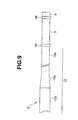
- Fig. 9shows a third embodiment of the present invention.
- the shape of an insertion unitis the same as that of the insertion unit 2 included in the first embodiment. The description of the insertion unit will therefore be omitted.
- At least one of connector sheathes 48 and 49 each linking portionsis mounted on the border between the distal section 8 of the insertion unit 2 and the bending section 9 thereof or between the bending section 9 and the small-diameter portion 10a that is the distal side of the soft section 10.
- both the connector sheathes 48 and 49are mounted.
- the connector sheathes 48 and 49are formed with any of various kinds of members, such as, hard tubular members, an adhesive, or soft heat contractile tubes.
- the endoscope included in the present embodimentis designed so that the outer diameter of the large-diameter portion 10b that is the operator side of the soft section 10 will be equal to (with ⁇ 5%) or slightly smaller than the outer diameter of the connector sheathes 48 and 49.
- the outer diameter of the connector sheathes 48 and 49is 12.8 mm
- the outer diameter of the large-diameter portion 10bis set to 12.8 mm
- the outer diameter of the small-diameter portion 10ais set to 11.5 mm.
- the outer diameter of the connector sheathes 48 and 49 of an endoscopeis generally larger than the outer diameter of the soft section 10. Therefore, when the endoscope is inserted into the large intestine, first, the lumen of the large intestine is observed using the distal section 8. If the distal section 8 and bending section 9 can be passed through a region in the large intestine, it will not be hard to pass the succeeding soft section 10 through the region.
- a sigmoid colon 30 shown in Fig. 7Awhen part of the sigmoid colon 30 shown in Fig. 7A is narrow, although the distal section 8 and bending section 9 can be passed through the part, it may be hard to pass the large-diameter section 10b through it. In this case, the insertion unit 2 cannot be smoothly advanced in the state shown in Fig. 7B. An operator may not find out the cause making it hard to advance the insertion unit 2 and may therefore not take proper measures.
- the outer diameter of the large-diameter portion 10bis substantially equal to or smaller than the outer diameter of the connector sheathes 48 and 49. Therefore, if the connector sheathes 48 and 49 can be passed through a region, the large-diameter portion 10b can be passed through it. Consequently, when the insertion unit 2 cannot be smoothly advanced any longer, since the cause does not lie in the thickness of the large-diameter portion 10b, the real cause may be inferred in the same manner as it is in the conventional endoscope insertion unit 2.
- At least one of the connector sheathes 48 and 49 each linking portionsis mounted on the border between the distal section 8 of the insertion unit 2 and the bending section 9 thereof or between the bending section 9 and the small-diameter portion 10a that is the distal side of the soft section 10.
- the outer diameter of the large-diameter portion 10b that is the operator side of the soft section 10is substantially equal to or slightly smaller than the outer diameter of the connector sheathes 48 and 49. Therefore, when the insertion unit 2 is inserted, the insertion will not be hindered because of the thickness of the large-diameter portion 10b. The great ease of insertion can be guaranteed.
- an operatorwill not have a feeling of wrongness when holding the large-diameter portions of the soft sections of a plurality of endoscopes included in one endoscope system.
- excellent insertion efficiencyis ensured.
Landscapes
- Health & Medical Sciences (AREA)
- Life Sciences & Earth Sciences (AREA)
- Surgery (AREA)
- Engineering & Computer Science (AREA)
- Biomedical Technology (AREA)
- Molecular Biology (AREA)
- Pathology (AREA)
- Radiology & Medical Imaging (AREA)
- Nuclear Medicine, Radiotherapy & Molecular Imaging (AREA)
- Biophysics (AREA)
- Physics & Mathematics (AREA)
- Heart & Thoracic Surgery (AREA)
- Medical Informatics (AREA)
- Optics & Photonics (AREA)
- Animal Behavior & Ethology (AREA)
- General Health & Medical Sciences (AREA)
- Public Health (AREA)
- Veterinary Medicine (AREA)
- Multimedia (AREA)
- Signal Processing (AREA)
- Manufacturing & Machinery (AREA)
- Endoscopes (AREA)
Abstract
Description
Claims (3)
- An endoscope system comprising: a first endoscopeincluding a soft section that has a small-diameter portionwhich is a distal portion and a large-diameter portion whichis formed proximally to the small-diameter portion and whoseouter diameter is larger than the outer diameter of thesmall-diameter portion; a second endoscope which shares thesame light source unit or video processor with the firstendoscope and whose soft section has substantially the sameouter diameter over the whole length thereof; and a thirdendoscope whose soft section has substantially the sameouter diameter over the whole length thereof and has theouter diameter substantially identical to or smaller thanthe outer diameter of the second endoscope, wherein:the outer diameter of at least the large-diameterportion of the first endoscope is substantially identical toor smaller than the outer diameter of the soft section ofthe second endoscope and is substantially identical to orlarger than the outer diameter of the soft section of thethird endoscope.
- An endoscope system according to Claim 1, wherein theouter diameter of the small-diameter portion of the firstendoscope is substantially identical to or larger than theouter diameter of the soft section of the third endoscope.
- An endoscope system according to Claim 1 or 2, whereinthe outer diameter of the small-diameter portion of thefirst endoscope is substantially identical to the outerdiameter of the soft section of the third endoscope, and theouter diameter of the large-diameter portion of the firstendoscope is substantially identical to the outer diameterof the soft-section of the second endoscope.
Applications Claiming Priority (3)
| Application Number | Priority Date | Filing Date | Title |
|---|---|---|---|
| JP2002311598 | 2002-10-25 | ||
| JP2002311598AJP4009519B2 (en) | 2002-10-25 | 2002-10-25 | Endoscope |
| PCT/JP2003/013463WO2004037075A1 (en) | 2002-10-25 | 2003-10-22 | Endoscope device |
Publications (3)
| Publication Number | Publication Date |
|---|---|
| EP1554972A1true EP1554972A1 (en) | 2005-07-20 |
| EP1554972A4 EP1554972A4 (en) | 2008-03-12 |
| EP1554972B1 EP1554972B1 (en) | 2018-04-11 |
Family
ID=32105317
Family Applications (2)
| Application Number | Title | Priority Date | Filing Date |
|---|---|---|---|
| EP03758757.3AExpired - LifetimeEP1554972B1 (en) | 2002-10-25 | 2003-10-22 | Endoscope device |
| EP03758759AWithdrawnEP1554973A4 (en) | 2002-10-25 | 2003-10-22 | Endoscope |
Family Applications After (1)
| Application Number | Title | Priority Date | Filing Date |
|---|---|---|---|
| EP03758759AWithdrawnEP1554973A4 (en) | 2002-10-25 | 2003-10-22 | Endoscope |
Country Status (7)
| Country | Link |
|---|---|
| US (2) | US20040106853A1 (en) |
| EP (2) | EP1554972B1 (en) |
| JP (1) | JP4009519B2 (en) |
| KR (2) | KR100685340B1 (en) |
| CN (2) | CN100502759C (en) |
| CA (2) | CA2501788C (en) |
| WO (2) | WO2004037075A1 (en) |
Families Citing this family (86)
| Publication number | Priority date | Publication date | Assignee | Title |
|---|---|---|---|---|
| JP2005081100A (en)* | 2003-09-11 | 2005-03-31 | Olympus Corp | Flexible tube of endoscope |
| JP2006014960A (en)* | 2004-07-01 | 2006-01-19 | Olympus Corp | Endoscope |
| US20060149127A1 (en)* | 2004-12-30 | 2006-07-06 | Seddiqui Fred R | Disposable multi-lumen catheter with reusable stylet |
| US8289381B2 (en) | 2005-01-05 | 2012-10-16 | Avantis Medical Systems, Inc. | Endoscope with an imaging catheter assembly and method of configuring an endoscope |
| US20080021274A1 (en)* | 2005-01-05 | 2008-01-24 | Avantis Medical Systems, Inc. | Endoscopic medical device with locking mechanism and method |
| US8797392B2 (en) | 2005-01-05 | 2014-08-05 | Avantis Medical Sytems, Inc. | Endoscope assembly with a polarizing filter |
| US8182422B2 (en) | 2005-12-13 | 2012-05-22 | Avantis Medical Systems, Inc. | Endoscope having detachable imaging device and method of using |
| US8872906B2 (en) | 2005-01-05 | 2014-10-28 | Avantis Medical Systems, Inc. | Endoscope assembly with a polarizing filter |
| US20070293720A1 (en)* | 2005-01-05 | 2007-12-20 | Avantis Medical Systems, Inc. | Endoscope assembly and method of viewing an area inside a cavity |
| WO2007087421A2 (en)* | 2006-01-23 | 2007-08-02 | Avantis Medical Systems, Inc. | Endoscope |
| US8287446B2 (en) | 2006-04-18 | 2012-10-16 | Avantis Medical Systems, Inc. | Vibratory device, endoscope having such a device, method for configuring an endoscope, and method of reducing looping of an endoscope |
| EP2023795A2 (en)* | 2006-05-19 | 2009-02-18 | Avantis Medical Systems, Inc. | Device and method for reducing effects of video artifacts |
| US7927272B2 (en)* | 2006-08-04 | 2011-04-19 | Avantis Medical Systems, Inc. | Surgical port with embedded imaging device |
| US9867530B2 (en) | 2006-08-14 | 2018-01-16 | Volcano Corporation | Telescopic side port catheter device with imaging system and method for accessing side branch occlusions |
| US20090231419A1 (en)* | 2007-02-06 | 2009-09-17 | Avantis Medical Systems, Inc. | Endoscope Assembly and Method of Performing a Medical Procedure |
| US8696551B2 (en)* | 2007-02-26 | 2014-04-15 | Machida Endoscope Co., Ltd. | Flexible endoscope suitable for MRI |
| US8064666B2 (en)* | 2007-04-10 | 2011-11-22 | Avantis Medical Systems, Inc. | Method and device for examining or imaging an interior surface of a cavity |
| EP2178442B1 (en)* | 2007-07-12 | 2017-09-06 | Volcano Corporation | Catheter for in vivo imaging |
| WO2009009802A1 (en) | 2007-07-12 | 2009-01-15 | Volcano Corporation | Oct-ivus catheter for concurrent luminal imaging |
| US9596993B2 (en) | 2007-07-12 | 2017-03-21 | Volcano Corporation | Automatic calibration systems and methods of use |
| FR2921499B1 (en)* | 2007-09-26 | 2009-11-13 | Snecma | CATHETER OR ENDOSCOPE-TYPE ORIENTABLE STRUCTURE |
| US20090213211A1 (en)* | 2007-10-11 | 2009-08-27 | Avantis Medical Systems, Inc. | Method and Device for Reducing the Fixed Pattern Noise of a Digital Image |
| JP2009226023A (en)* | 2008-03-24 | 2009-10-08 | Fujifilm Corp | Method for manufacturing flexible tube for endoscope |
| CN110074746B (en)* | 2008-10-20 | 2021-11-26 | 智能医疗系统有限公司 | Assembly for use in an endoscope and use thereof |
| JP5371822B2 (en)* | 2010-02-15 | 2013-12-18 | オリンパス株式会社 | Endoscope |
| US11141063B2 (en) | 2010-12-23 | 2021-10-12 | Philips Image Guided Therapy Corporation | Integrated system architectures and methods of use |
| US11040140B2 (en) | 2010-12-31 | 2021-06-22 | Philips Image Guided Therapy Corporation | Deep vein thrombosis therapeutic methods |
| JP5427824B2 (en)* | 2011-04-14 | 2014-02-26 | 富士フイルム株式会社 | Endoscope |
| US9360630B2 (en) | 2011-08-31 | 2016-06-07 | Volcano Corporation | Optical-electrical rotary joint and methods of use |
| JP5390048B1 (en)* | 2012-05-14 | 2014-01-15 | オリンパスメディカルシステムズ株式会社 | Endoscope system |
| JP5810037B2 (en)* | 2012-06-04 | 2015-11-11 | オリンパス株式会社 | Endoscope system |
| US9286673B2 (en) | 2012-10-05 | 2016-03-15 | Volcano Corporation | Systems for correcting distortions in a medical image and methods of use thereof |
| US10070827B2 (en) | 2012-10-05 | 2018-09-11 | Volcano Corporation | Automatic image playback |
| US9367965B2 (en) | 2012-10-05 | 2016-06-14 | Volcano Corporation | Systems and methods for generating images of tissue |
| US10568586B2 (en) | 2012-10-05 | 2020-02-25 | Volcano Corporation | Systems for indicating parameters in an imaging data set and methods of use |
| US9324141B2 (en) | 2012-10-05 | 2016-04-26 | Volcano Corporation | Removal of A-scan streaking artifact |
| US9292918B2 (en) | 2012-10-05 | 2016-03-22 | Volcano Corporation | Methods and systems for transforming luminal images |
| US11272845B2 (en) | 2012-10-05 | 2022-03-15 | Philips Image Guided Therapy Corporation | System and method for instant and automatic border detection |
| US9858668B2 (en) | 2012-10-05 | 2018-01-02 | Volcano Corporation | Guidewire artifact removal in images |
| US9307926B2 (en) | 2012-10-05 | 2016-04-12 | Volcano Corporation | Automatic stent detection |
| US20140100454A1 (en) | 2012-10-05 | 2014-04-10 | Volcano Corporation | Methods and systems for establishing parameters for three-dimensional imaging |
| CA2887421A1 (en) | 2012-10-05 | 2014-04-10 | David Welford | Systems and methods for amplifying light |
| US9840734B2 (en) | 2012-10-22 | 2017-12-12 | Raindance Technologies, Inc. | Methods for analyzing DNA |
| EP2931132B1 (en) | 2012-12-13 | 2023-07-05 | Philips Image Guided Therapy Corporation | System for targeted cannulation |
| WO2014113188A2 (en) | 2012-12-20 | 2014-07-24 | Jeremy Stigall | Locating intravascular images |
| EP2934310A4 (en) | 2012-12-20 | 2016-10-12 | Nathaniel J Kemp | Optical coherence tomography system that is reconfigurable between different imaging modes |
| US10939826B2 (en) | 2012-12-20 | 2021-03-09 | Philips Image Guided Therapy Corporation | Aspirating and removing biological material |
| EP2934311B1 (en) | 2012-12-20 | 2020-04-15 | Volcano Corporation | Smooth transition catheters |
| US10942022B2 (en) | 2012-12-20 | 2021-03-09 | Philips Image Guided Therapy Corporation | Manual calibration of imaging system |
| US11406498B2 (en) | 2012-12-20 | 2022-08-09 | Philips Image Guided Therapy Corporation | Implant delivery system and implants |
| CA2895769A1 (en) | 2012-12-21 | 2014-06-26 | Douglas Meyer | Rotational ultrasound imaging catheter with extended catheter body telescope |
| JP2016507892A (en) | 2012-12-21 | 2016-03-10 | デイビッド ウェルフォード, | System and method for narrowing the wavelength emission of light |
| US9612105B2 (en) | 2012-12-21 | 2017-04-04 | Volcano Corporation | Polarization sensitive optical coherence tomography system |
| US10413317B2 (en) | 2012-12-21 | 2019-09-17 | Volcano Corporation | System and method for catheter steering and operation |
| US10332228B2 (en) | 2012-12-21 | 2019-06-25 | Volcano Corporation | System and method for graphical processing of medical data |
| EP2936241B1 (en) | 2012-12-21 | 2020-10-21 | Nathaniel J. Kemp | Power-efficient optical buffering using a polarisation-maintaining active optical switch |
| US10058284B2 (en) | 2012-12-21 | 2018-08-28 | Volcano Corporation | Simultaneous imaging, monitoring, and therapy |
| US9486143B2 (en) | 2012-12-21 | 2016-11-08 | Volcano Corporation | Intravascular forward imaging device |
| JP2016501625A (en) | 2012-12-21 | 2016-01-21 | ジェローム マイ, | Ultrasound imaging with variable line density |
| EP2934323A4 (en) | 2012-12-21 | 2016-08-17 | Andrew Hancock | SYSTEM AND METHOD FOR MULTIPLE PROCESSING OF IMAGE SIGNALS |
| WO2014138555A1 (en) | 2013-03-07 | 2014-09-12 | Bernhard Sturm | Multimodal segmentation in intravascular images |
| US10226597B2 (en) | 2013-03-07 | 2019-03-12 | Volcano Corporation | Guidewire with centering mechanism |
| US20140276923A1 (en) | 2013-03-12 | 2014-09-18 | Volcano Corporation | Vibrating catheter and methods of use |
| EP2967391A4 (en) | 2013-03-12 | 2016-11-02 | Donna Collins | SYSTEMS AND METHODS FOR DIAGNOSING CORONARY MICROVASCULAR DISEASE |
| US11026591B2 (en) | 2013-03-13 | 2021-06-08 | Philips Image Guided Therapy Corporation | Intravascular pressure sensor calibration |
| WO2014159819A1 (en) | 2013-03-13 | 2014-10-02 | Jinhyoung Park | System and methods for producing an image from a rotational intravascular ultrasound device |
| US9301687B2 (en) | 2013-03-13 | 2016-04-05 | Volcano Corporation | System and method for OCT depth calibration |
| US10292677B2 (en) | 2013-03-14 | 2019-05-21 | Volcano Corporation | Endoluminal filter having enhanced echogenic properties |
| US10219887B2 (en) | 2013-03-14 | 2019-03-05 | Volcano Corporation | Filters with echogenic characteristics |
| US20160030151A1 (en) | 2013-03-14 | 2016-02-04 | Volcano Corporation | Filters with echogenic characteristics |
| US12343198B2 (en) | 2013-03-14 | 2025-07-01 | Philips Image Guided Therapy Corporation | Delivery catheter having imaging capabilities |
| WO2014192510A1 (en)* | 2013-05-28 | 2014-12-04 | オリンパスメディカルシステムズ株式会社 | Endoscope and endoscope manufacturing method |
| JP5968939B2 (en) | 2014-03-26 | 2016-08-10 | 富士フイルム株式会社 | Endoscopic flexible tube and manufacturing method thereof |
| US9433340B2 (en) | 2014-05-30 | 2016-09-06 | Endoscopic Innovations LLC | System and method for rapid shuttling of tools through endoscopes |
| JP6368256B2 (en)* | 2015-02-05 | 2018-08-01 | 富士フイルム株式会社 | Endoscope system |
| US11553832B2 (en)* | 2015-06-05 | 2023-01-17 | Fujifilm Corporation | Endoscope system |
| WO2017109988A1 (en) | 2015-12-25 | 2017-06-29 | オリンパス株式会社 | Flexible tube insertion device |
| US10779715B2 (en)* | 2017-02-23 | 2020-09-22 | Sony Olympus Medical Solutions Inc. | Endoscope apparatus |
| JP6950079B2 (en) | 2018-03-27 | 2021-10-13 | オリンパス株式会社 | How to operate the flexible tube insertion device, insertion control device, and flexible tube insertion device |
| JP7545892B2 (en) | 2018-07-06 | 2024-09-05 | Hoya株式会社 | Endoscopy |
| JP7382149B2 (en)* | 2019-03-19 | 2023-11-16 | 住友理工株式会社 | multilayer tube |
| EP3827731B1 (en)* | 2019-11-26 | 2025-03-26 | Karl Storz SE & Co. KG | Endoscope device for flexible endoscope and method of manufacture thereof |
| US20230225596A1 (en)* | 2019-12-09 | 2023-07-20 | Nitesh Ratnakar | Shape memory endoscope insertion tube sheath |
| CN112587068B (en)* | 2021-03-02 | 2021-06-29 | 岱川医疗(深圳)有限责任公司 | Endoscope insertion tube, method for processing outer skin layer thereof, and endoscope |
| CN112587071B (en)* | 2021-03-02 | 2021-06-08 | 岱川医疗(深圳)有限责任公司 | Insertion tube for endoscope and method for manufacturing insertion tube for endoscope |
| US20250261837A1 (en)* | 2024-02-20 | 2025-08-21 | Boston Scientific Scimed, Inc. | Shafts of medical devices and related devices, systems, and methods |
Family Cites Families (24)
| Publication number | Priority date | Publication date | Assignee | Title |
|---|---|---|---|---|
| US2269823A (en)* | 1939-11-24 | 1942-01-13 | Kreiselman Joseph | Insufflation apparatus |
| US4690175A (en)* | 1981-11-17 | 1987-09-01 | Kabushiki Kaisha Medos Kenkyusho | Flexible tube for endoscope |
| DE3504252A1 (en)* | 1985-02-08 | 1986-08-14 | Richard Wolf Gmbh, 7134 Knittlingen | URETERO RENOSCOPE |
| JPH0346721Y2 (en)* | 1987-07-09 | 1991-10-03 | ||
| US5083549A (en)* | 1989-02-06 | 1992-01-28 | Candela Laser Corporation | Endoscope with tapered shaft |
| US5084022A (en)* | 1989-10-04 | 1992-01-28 | Lake Region Manufacturing Company, Inc. | Graduated guidewire |
| JP2926189B2 (en)* | 1990-05-14 | 1999-07-28 | 旭光学工業株式会社 | Flexible tube for endoscope and method for manufacturing the same |
| FR2691069B1 (en)* | 1992-05-14 | 1999-08-20 | Vygon | SURGICAL INSTRUMENT FOR PERIDURAL ANESTHESIA OPERATION. |
| US5390661A (en)* | 1993-02-03 | 1995-02-21 | W. L. Gore & Associates, Inc. | Introducer for esophageal probes |
| JP3519823B2 (en)* | 1995-05-31 | 2004-04-19 | オリンパス株式会社 | Cover-type endoscope |
| JPH09276244A (en)* | 1996-04-16 | 1997-10-28 | Olympus Optical Co Ltd | In-celom probe for nuclear magnetic resonance diagnostic device |
| US5885208A (en)* | 1996-12-24 | 1999-03-23 | Olympus Optical Co., Ltd. | Endoscope system |
| JP3813706B2 (en)* | 1997-07-24 | 2006-08-23 | オリンパス株式会社 | Endoscope system |
| US6524299B1 (en)* | 1997-04-09 | 2003-02-25 | Target Therapeutics, Inc. | Flow-directed catheter |
| US6117128A (en)* | 1997-04-30 | 2000-09-12 | Kenton W. Gregory | Energy delivery catheter and method for the use thereof |
| US5916147A (en)* | 1997-09-22 | 1999-06-29 | Boury; Harb N. | Selectively manipulable catheter |
| JP2000137172A (en)* | 1998-10-29 | 2000-05-16 | Olympus Optical Co Ltd | Image pickup device |
| US6690410B1 (en)* | 1999-06-09 | 2004-02-10 | Olympus Optical Co., Ltd. | Image processing unit with expandable image signal processing capability and endoscopic imaging system |
| JP3396190B2 (en)* | 1998-11-26 | 2003-04-14 | オリンパス光学工業株式会社 | Image processing device |
| JP2001029313A (en)* | 1999-05-18 | 2001-02-06 | Olympus Optical Co Ltd | Endoscope device |
| EP1185200B1 (en)* | 1999-06-05 | 2008-01-09 | Wilson-Cook Medical Inc. | Indicia for an endoscopic medical device |
| JP4412785B2 (en)* | 2000-01-06 | 2010-02-10 | Hoya株式会社 | Endoscope flexible tube |
| JP4429495B2 (en)* | 2000-07-28 | 2010-03-10 | オリンパス株式会社 | Endoscope |
| JP3600194B2 (en)* | 2000-10-02 | 2004-12-08 | オリンパス株式会社 | Endoscope |
- 2002
- 2002-10-25JPJP2002311598Apatent/JP4009519B2/ennot_activeExpired - Fee Related
- 2003
- 2003-10-21USUS10/690,404patent/US20040106853A1/ennot_activeAbandoned
- 2003-10-21USUS10/690,403patent/US20040080613A1/ennot_activeAbandoned
- 2003-10-22EPEP03758757.3Apatent/EP1554972B1/ennot_activeExpired - Lifetime
- 2003-10-22CNCNB2003801020869Apatent/CN100502759C/ennot_activeExpired - Fee Related
- 2003-10-22KRKR1020057005425Apatent/KR100685340B1/ennot_activeExpired - Fee Related
- 2003-10-22EPEP03758759Apatent/EP1554973A4/ennot_activeWithdrawn
- 2003-10-22KRKR1020057005424Apatent/KR100690467B1/ennot_activeExpired - Fee Related
- 2003-10-22WOPCT/JP2003/013463patent/WO2004037075A1/enactiveApplication Filing
- 2003-10-22CNCNB2003801020905Apatent/CN100376199C/ennot_activeExpired - Fee Related
- 2003-10-22WOPCT/JP2003/013465patent/WO2004037076A1/enactiveApplication Filing
- 2003-10-22CACA2501788Apatent/CA2501788C/ennot_activeExpired - Fee Related
- 2003-10-22CACA002501662Apatent/CA2501662C/ennot_activeExpired - Fee Related
Also Published As
| Publication number | Publication date |
|---|---|
| CA2501788A1 (en) | 2004-05-06 |
| KR20050063773A (en) | 2005-06-28 |
| WO2004037076A1 (en) | 2004-05-06 |
| CN1708253A (en) | 2005-12-14 |
| EP1554973A1 (en) | 2005-07-20 |
| EP1554972A4 (en) | 2008-03-12 |
| CN100376199C (en) | 2008-03-26 |
| JP2004141492A (en) | 2004-05-20 |
| EP1554973A4 (en) | 2008-03-12 |
| WO2004037075A1 (en) | 2004-05-06 |
| US20040106853A1 (en) | 2004-06-03 |
| EP1554972B1 (en) | 2018-04-11 |
| JP4009519B2 (en) | 2007-11-14 |
| CN100502759C (en) | 2009-06-24 |
| CN1708252A (en) | 2005-12-14 |
| KR100685340B1 (en) | 2007-02-26 |
| KR20050063772A (en) | 2005-06-28 |
| CA2501662C (en) | 2008-04-29 |
| US20040080613A1 (en) | 2004-04-29 |
| CA2501662A1 (en) | 2004-05-06 |
| KR100690467B1 (en) | 2007-03-12 |
| CA2501788C (en) | 2011-12-13 |
Similar Documents
| Publication | Publication Date | Title |
|---|---|---|
| CA2501662C (en) | Endoscope system | |
| JP4477519B2 (en) | Endoscope | |
| CN101106932B (en) | endoscope | |
| EP2702925B1 (en) | Endoscope system | |
| CN1767869A (en) | Guidewire structure for insertion into the inner space | |
| JP5927103B2 (en) | Endoscope insertion part, endoscope, and bending stiffness profile correction tool | |
| JP3923701B2 (en) | Endoscope | |
| CN108348135B (en) | Endoscope system | |
| JP2002143084A (en) | Endoscope device | |
| JP3756874B2 (en) | Endoscope | |
| JP2025503395A (en) | Systems and methods for robotic endoscope shafts | |
| CN116407071A (en) | Endoscope insertion tube and endoscope | |
| JPH10314106A (en) | Endoscope | |
| JP4005080B2 (en) | Endoscope device | |
| JP2012213572A (en) | Supplementary observation device for endoscope | |
| JPH1099264A (en) | Endoscope | |
| JPH06277174A (en) | Endoscope apparatus | |
| JP3597416B2 (en) | Endoscope | |
| KR20140126974A (en) | Endoscope | |
| JP2003275167A (en) | Endoscope |
Legal Events
| Date | Code | Title | Description |
|---|---|---|---|
| PUAI | Public reference made under article 153(3) epc to a published international application that has entered the european phase | Free format text:ORIGINAL CODE: 0009012 | |
| 17P | Request for examination filed | Effective date:20050415 | |
| AK | Designated contracting states | Kind code of ref document:A1 Designated state(s):AT BE BG CH CY CZ DE DK EE ES FI FR GB GR HU IE IT LI LU MC NL PT RO SE SI SK TR | |
| A4 | Supplementary search report drawn up and despatched | Effective date:20080211 | |
| 17Q | First examination report despatched | Effective date:20090317 | |
| RAP1 | Party data changed (applicant data changed or rights of an application transferred) | Owner name:OLYMPUS CORPORATION | |
| RAP1 | Party data changed (applicant data changed or rights of an application transferred) | Owner name:OLYMPUS CORPORATION | |
| REG | Reference to a national code | Ref country code:DE Ref legal event code:R079 Ref document number:60351114 Country of ref document:DE Free format text:PREVIOUS MAIN CLASS: A61B0001000000 Ipc:A61B0001005000 | |
| RIC1 | Information provided on ipc code assigned before grant | Ipc:A61B 1/00 20060101ALI20170904BHEP Ipc:A61B 1/31 20060101ALI20170904BHEP Ipc:A61B 1/005 20060101AFI20170904BHEP | |
| GRAP | Despatch of communication of intention to grant a patent | Free format text:ORIGINAL CODE: EPIDOSNIGR1 | |
| INTG | Intention to grant announced | Effective date:20171017 | |
| GRAS | Grant fee paid | Free format text:ORIGINAL CODE: EPIDOSNIGR3 | |
| GRAA | (expected) grant | Free format text:ORIGINAL CODE: 0009210 | |
| STAA | Information on the status of an ep patent application or granted ep patent | Free format text:STATUS: THE PATENT HAS BEEN GRANTED | |
| AK | Designated contracting states | Kind code of ref document:B1 Designated state(s):AT BE BG CH CY CZ DE DK EE ES FI FR GB GR HU IE IT LI LU MC NL PT RO SE SI SK TR | |
| REG | Reference to a national code | Ref country code:GB Ref legal event code:FG4D | |
| REG | Reference to a national code | Ref country code:CH Ref legal event code:EP | |
| REG | Reference to a national code | Ref country code:AT Ref legal event code:REF Ref document number:987097 Country of ref document:AT Kind code of ref document:T Effective date:20180415 | |
| REG | Reference to a national code | Ref country code:IE Ref legal event code:FG4D | |
| REG | Reference to a national code | Ref country code:DE Ref legal event code:R096 Ref document number:60351114 Country of ref document:DE | |
| REG | Reference to a national code | Ref country code:NL Ref legal event code:MP Effective date:20180411 | |
| PG25 | Lapsed in a contracting state [announced via postgrant information from national office to epo] | Ref country code:NL Free format text:LAPSE BECAUSE OF FAILURE TO SUBMIT A TRANSLATION OF THE DESCRIPTION OR TO PAY THE FEE WITHIN THE PRESCRIBED TIME-LIMIT Effective date:20180411 | |
| PG25 | Lapsed in a contracting state [announced via postgrant information from national office to epo] | Ref country code:BG Free format text:LAPSE BECAUSE OF FAILURE TO SUBMIT A TRANSLATION OF THE DESCRIPTION OR TO PAY THE FEE WITHIN THE PRESCRIBED TIME-LIMIT Effective date:20180711 Ref country code:FI Free format text:LAPSE BECAUSE OF FAILURE TO SUBMIT A TRANSLATION OF THE DESCRIPTION OR TO PAY THE FEE WITHIN THE PRESCRIBED TIME-LIMIT Effective date:20180411 Ref country code:SE Free format text:LAPSE BECAUSE OF FAILURE TO SUBMIT A TRANSLATION OF THE DESCRIPTION OR TO PAY THE FEE WITHIN THE PRESCRIBED TIME-LIMIT Effective date:20180411 Ref country code:ES Free format text:LAPSE BECAUSE OF FAILURE TO SUBMIT A TRANSLATION OF THE DESCRIPTION OR TO PAY THE FEE WITHIN THE PRESCRIBED TIME-LIMIT Effective date:20180411 | |
| PG25 | Lapsed in a contracting state [announced via postgrant information from national office to epo] | Ref country code:GR Free format text:LAPSE BECAUSE OF FAILURE TO SUBMIT A TRANSLATION OF THE DESCRIPTION OR TO PAY THE FEE WITHIN THE PRESCRIBED TIME-LIMIT Effective date:20180712 | |
| REG | Reference to a national code | Ref country code:AT Ref legal event code:MK05 Ref document number:987097 Country of ref document:AT Kind code of ref document:T Effective date:20180411 | |
| PG25 | Lapsed in a contracting state [announced via postgrant information from national office to epo] | Ref country code:PT Free format text:LAPSE BECAUSE OF FAILURE TO SUBMIT A TRANSLATION OF THE DESCRIPTION OR TO PAY THE FEE WITHIN THE PRESCRIBED TIME-LIMIT Effective date:20180813 | |
| REG | Reference to a national code | Ref country code:DE Ref legal event code:R097 Ref document number:60351114 Country of ref document:DE | |
| PG25 | Lapsed in a contracting state [announced via postgrant information from national office to epo] | Ref country code:RO Free format text:LAPSE BECAUSE OF FAILURE TO SUBMIT A TRANSLATION OF THE DESCRIPTION OR TO PAY THE FEE WITHIN THE PRESCRIBED TIME-LIMIT Effective date:20180411 Ref country code:SK Free format text:LAPSE BECAUSE OF FAILURE TO SUBMIT A TRANSLATION OF THE DESCRIPTION OR TO PAY THE FEE WITHIN THE PRESCRIBED TIME-LIMIT Effective date:20180411 Ref country code:CZ Free format text:LAPSE BECAUSE OF FAILURE TO SUBMIT A TRANSLATION OF THE DESCRIPTION OR TO PAY THE FEE WITHIN THE PRESCRIBED TIME-LIMIT Effective date:20180411 Ref country code:DK Free format text:LAPSE BECAUSE OF FAILURE TO SUBMIT A TRANSLATION OF THE DESCRIPTION OR TO PAY THE FEE WITHIN THE PRESCRIBED TIME-LIMIT Effective date:20180411 Ref country code:AT Free format text:LAPSE BECAUSE OF FAILURE TO SUBMIT A TRANSLATION OF THE DESCRIPTION OR TO PAY THE FEE WITHIN THE PRESCRIBED TIME-LIMIT Effective date:20180411 Ref country code:EE Free format text:LAPSE BECAUSE OF FAILURE TO SUBMIT A TRANSLATION OF THE DESCRIPTION OR TO PAY THE FEE WITHIN THE PRESCRIBED TIME-LIMIT Effective date:20180411 | |
| PLBE | No opposition filed within time limit | Free format text:ORIGINAL CODE: 0009261 | |
| STAA | Information on the status of an ep patent application or granted ep patent | Free format text:STATUS: NO OPPOSITION FILED WITHIN TIME LIMIT | |
| PG25 | Lapsed in a contracting state [announced via postgrant information from national office to epo] | Ref country code:IT Free format text:LAPSE BECAUSE OF FAILURE TO SUBMIT A TRANSLATION OF THE DESCRIPTION OR TO PAY THE FEE WITHIN THE PRESCRIBED TIME-LIMIT Effective date:20180411 | |
| 26N | No opposition filed | Effective date:20190114 | |
| PG25 | Lapsed in a contracting state [announced via postgrant information from national office to epo] | Ref country code:SI Free format text:LAPSE BECAUSE OF FAILURE TO SUBMIT A TRANSLATION OF THE DESCRIPTION OR TO PAY THE FEE WITHIN THE PRESCRIBED TIME-LIMIT Effective date:20180411 | |
| REG | Reference to a national code | Ref country code:CH Ref legal event code:PL | |
| GBPC | Gb: european patent ceased through non-payment of renewal fee | Effective date:20181022 | |
| REG | Reference to a national code | Ref country code:BE Ref legal event code:MM Effective date:20181031 | |
| PG25 | Lapsed in a contracting state [announced via postgrant information from national office to epo] | Ref country code:LU Free format text:LAPSE BECAUSE OF NON-PAYMENT OF DUE FEES Effective date:20181022 Ref country code:MC Free format text:LAPSE BECAUSE OF FAILURE TO SUBMIT A TRANSLATION OF THE DESCRIPTION OR TO PAY THE FEE WITHIN THE PRESCRIBED TIME-LIMIT Effective date:20180411 | |
| REG | Reference to a national code | Ref country code:IE Ref legal event code:MM4A | |
| PG25 | Lapsed in a contracting state [announced via postgrant information from national office to epo] | Ref country code:BE Free format text:LAPSE BECAUSE OF NON-PAYMENT OF DUE FEES Effective date:20181031 Ref country code:LI Free format text:LAPSE BECAUSE OF NON-PAYMENT OF DUE FEES Effective date:20181031 Ref country code:CH Free format text:LAPSE BECAUSE OF NON-PAYMENT OF DUE FEES Effective date:20181031 Ref country code:FR Free format text:LAPSE BECAUSE OF NON-PAYMENT OF DUE FEES Effective date:20181031 | |
| PG25 | Lapsed in a contracting state [announced via postgrant information from national office to epo] | Ref country code:IE Free format text:LAPSE BECAUSE OF NON-PAYMENT OF DUE FEES Effective date:20181022 Ref country code:GB Free format text:LAPSE BECAUSE OF NON-PAYMENT OF DUE FEES Effective date:20181022 | |
| PG25 | Lapsed in a contracting state [announced via postgrant information from national office to epo] | Ref country code:TR Free format text:LAPSE BECAUSE OF FAILURE TO SUBMIT A TRANSLATION OF THE DESCRIPTION OR TO PAY THE FEE WITHIN THE PRESCRIBED TIME-LIMIT Effective date:20180411 | |
| PG25 | Lapsed in a contracting state [announced via postgrant information from national office to epo] | Ref country code:HU Free format text:LAPSE BECAUSE OF FAILURE TO SUBMIT A TRANSLATION OF THE DESCRIPTION OR TO PAY THE FEE WITHIN THE PRESCRIBED TIME-LIMIT; INVALID AB INITIO Effective date:20031022 Ref country code:CY Free format text:LAPSE BECAUSE OF FAILURE TO SUBMIT A TRANSLATION OF THE DESCRIPTION OR TO PAY THE FEE WITHIN THE PRESCRIBED TIME-LIMIT Effective date:20180411 | |
| PGFP | Annual fee paid to national office [announced via postgrant information from national office to epo] | Ref country code:DE Payment date:20211020 Year of fee payment:19 | |
| REG | Reference to a national code | Ref country code:DE Ref legal event code:R119 Ref document number:60351114 Country of ref document:DE | |
| PG25 | Lapsed in a contracting state [announced via postgrant information from national office to epo] | Ref country code:DE Free format text:LAPSE BECAUSE OF NON-PAYMENT OF DUE FEES Effective date:20230503 |