EP1551482B1 - Single use syringe having safety shield - Google Patents
Single use syringe having safety shieldDownload PDFInfo
- Publication number
- EP1551482B1 EP1551482B1EP03770615AEP03770615AEP1551482B1EP 1551482 B1EP1551482 B1EP 1551482B1EP 03770615 AEP03770615 AEP 03770615AEP 03770615 AEP03770615 AEP 03770615AEP 1551482 B1EP1551482 B1EP 1551482B1
- Authority
- EP
- European Patent Office
- Prior art keywords
- plunger
- barrel
- needle
- locking
- fluid
- Prior art date
- Legal status (The legal status is an assumption and is not a legal conclusion. Google has not performed a legal analysis and makes no representation as to the accuracy of the status listed.)
- Expired - Lifetime
Links
- 239000012530fluidSubstances0.000claimsabstractdescription35
- 238000004891communicationMethods0.000claimsabstractdescription13
- 230000003313weakening effectEffects0.000claimsdescription3
- 230000002829reductive effectEffects0.000claimsdescription2
- 238000002347injectionMethods0.000description18
- 239000007924injectionSubstances0.000description18
- 230000007246mechanismEffects0.000description9
- 201000010099diseaseDiseases0.000description4
- 208000037265diseases, disorders, signs and symptomsDiseases0.000description4
- 239000003814drugSubstances0.000description4
- 230000036961partial effectEffects0.000description4
- 230000004913activationEffects0.000description3
- 230000008901benefitEffects0.000description3
- 229940079593drugDrugs0.000description3
- 230000013011matingEffects0.000description3
- 238000000034methodMethods0.000description3
- 239000008223sterile waterSubstances0.000description3
- 210000003813thumbAnatomy0.000description3
- XLYOFNOQVPJJNP-UHFFFAOYSA-NwaterChemical compoundOXLYOFNOQVPJJNP-UHFFFAOYSA-N0.000description3
- 206010013654Drug abuseDiseases0.000description2
- 206010069803Injury associated with deviceDiseases0.000description2
- 230000006835compressionEffects0.000description2
- 238000007906compressionMethods0.000description2
- 238000001990intravenous administrationMethods0.000description2
- 239000000463materialSubstances0.000description2
- 208000011117substance-related diseaseDiseases0.000description2
- 208000030507AIDSDiseases0.000description1
- 230000009471actionEffects0.000description1
- 239000000853adhesiveSubstances0.000description1
- 230000001070adhesive effectEffects0.000description1
- 239000003708ampulSubstances0.000description1
- 230000000712assemblyEffects0.000description1
- 238000000429assemblyMethods0.000description1
- 239000008280bloodSubstances0.000description1
- 210000004369bloodAnatomy0.000description1
- 238000010276constructionMethods0.000description1
- 230000006378damageEffects0.000description1
- 230000007423decreaseEffects0.000description1
- 230000000994depressogenic effectEffects0.000description1
- 230000001066destructive effectEffects0.000description1
- 239000000428dustSubstances0.000description1
- 230000000694effectsEffects0.000description1
- 208000015181infectious diseaseDiseases0.000description1
- 230000003993interactionEffects0.000description1
- 239000007788liquidSubstances0.000description1
- 238000012986modificationMethods0.000description1
- 230000004048modificationEffects0.000description1
- 244000052769pathogenSpecies0.000description1
- 230000002028prematureEffects0.000description1
- 230000001681protective effectEffects0.000description1
- 238000009877renderingMethods0.000description1
- 230000002441reversible effectEffects0.000description1
- 238000007789sealingMethods0.000description1
- 238000003466weldingMethods0.000description1
Images


Classifications
- A—HUMAN NECESSITIES
- A61—MEDICAL OR VETERINARY SCIENCE; HYGIENE
- A61M—DEVICES FOR INTRODUCING MEDIA INTO, OR ONTO, THE BODY; DEVICES FOR TRANSDUCING BODY MEDIA OR FOR TAKING MEDIA FROM THE BODY; DEVICES FOR PRODUCING OR ENDING SLEEP OR STUPOR
- A61M5/00—Devices for bringing media into the body in a subcutaneous, intra-vascular or intramuscular way; Accessories therefor, e.g. filling or cleaning devices, arm-rests
- A61M5/178—Syringes
- A61M5/31—Details
- A61M5/32—Needles; Details of needles pertaining to their connection with syringe or hub; Accessories for bringing the needle into, or holding the needle on, the body; Devices for protection of needles
- A61M5/3205—Apparatus for removing or disposing of used needles or syringes, e.g. containers; Means for protection against accidental injuries from used needles
- A61M5/321—Means for protection against accidental injuries by used needles
- A61M5/3216—Caps placed transversally onto the needle, e.g. pivotally attached to the needle base
- A—HUMAN NECESSITIES
- A61—MEDICAL OR VETERINARY SCIENCE; HYGIENE
- A61M—DEVICES FOR INTRODUCING MEDIA INTO, OR ONTO, THE BODY; DEVICES FOR TRANSDUCING BODY MEDIA OR FOR TAKING MEDIA FROM THE BODY; DEVICES FOR PRODUCING OR ENDING SLEEP OR STUPOR
- A61M5/00—Devices for bringing media into the body in a subcutaneous, intra-vascular or intramuscular way; Accessories therefor, e.g. filling or cleaning devices, arm-rests
- A61M5/178—Syringes
- A61M5/31—Details
- A61M5/32—Needles; Details of needles pertaining to their connection with syringe or hub; Accessories for bringing the needle into, or holding the needle on, the body; Devices for protection of needles
- A—HUMAN NECESSITIES
- A61—MEDICAL OR VETERINARY SCIENCE; HYGIENE
- A61M—DEVICES FOR INTRODUCING MEDIA INTO, OR ONTO, THE BODY; DEVICES FOR TRANSDUCING BODY MEDIA OR FOR TAKING MEDIA FROM THE BODY; DEVICES FOR PRODUCING OR ENDING SLEEP OR STUPOR
- A61M5/00—Devices for bringing media into the body in a subcutaneous, intra-vascular or intramuscular way; Accessories therefor, e.g. filling or cleaning devices, arm-rests
- A61M5/50—Devices for bringing media into the body in a subcutaneous, intra-vascular or intramuscular way; Accessories therefor, e.g. filling or cleaning devices, arm-rests having means for preventing re-use, or for indicating if defective, used, tampered with or unsterile
- A61M5/5066—Means for preventing re-use by disconnection of piston and piston-rod
- A61M2005/5073—Means for preventing re-use by disconnection of piston and piston-rod by breaking or rupturing the connection parts
- A—HUMAN NECESSITIES
- A61—MEDICAL OR VETERINARY SCIENCE; HYGIENE
- A61M—DEVICES FOR INTRODUCING MEDIA INTO, OR ONTO, THE BODY; DEVICES FOR TRANSDUCING BODY MEDIA OR FOR TAKING MEDIA FROM THE BODY; DEVICES FOR PRODUCING OR ENDING SLEEP OR STUPOR
- A61M5/00—Devices for bringing media into the body in a subcutaneous, intra-vascular or intramuscular way; Accessories therefor, e.g. filling or cleaning devices, arm-rests
- A61M5/178—Syringes
- A61M5/31—Details
- A61M5/315—Pistons; Piston-rods; Guiding, blocking or restricting the movement of the rod or piston; Appliances on the rod for facilitating dosing ; Dosing mechanisms
- A61M5/31511—Piston or piston-rod constructions, e.g. connection of piston with piston-rod
- A61M5/31513—Piston constructions to improve sealing or sliding
- A—HUMAN NECESSITIES
- A61—MEDICAL OR VETERINARY SCIENCE; HYGIENE
- A61M—DEVICES FOR INTRODUCING MEDIA INTO, OR ONTO, THE BODY; DEVICES FOR TRANSDUCING BODY MEDIA OR FOR TAKING MEDIA FROM THE BODY; DEVICES FOR PRODUCING OR ENDING SLEEP OR STUPOR
- A61M5/00—Devices for bringing media into the body in a subcutaneous, intra-vascular or intramuscular way; Accessories therefor, e.g. filling or cleaning devices, arm-rests
- A61M5/178—Syringes
- A61M5/31—Details
- A61M5/32—Needles; Details of needles pertaining to their connection with syringe or hub; Accessories for bringing the needle into, or holding the needle on, the body; Devices for protection of needles
- A61M5/34—Constructions for connecting the needle, e.g. to syringe nozzle or needle hub
- A61M5/347—Constructions for connecting the needle, e.g. to syringe nozzle or needle hub rotatable, e.g. bayonet or screw
- A—HUMAN NECESSITIES
- A61—MEDICAL OR VETERINARY SCIENCE; HYGIENE
- A61M—DEVICES FOR INTRODUCING MEDIA INTO, OR ONTO, THE BODY; DEVICES FOR TRANSDUCING BODY MEDIA OR FOR TAKING MEDIA FROM THE BODY; DEVICES FOR PRODUCING OR ENDING SLEEP OR STUPOR
- A61M5/00—Devices for bringing media into the body in a subcutaneous, intra-vascular or intramuscular way; Accessories therefor, e.g. filling or cleaning devices, arm-rests
- A61M5/50—Devices for bringing media into the body in a subcutaneous, intra-vascular or intramuscular way; Accessories therefor, e.g. filling or cleaning devices, arm-rests having means for preventing re-use, or for indicating if defective, used, tampered with or unsterile
- A61M5/5013—Means for blocking the piston or the fluid passageway to prevent illegal refilling of a syringe
- A61M5/502—Means for blocking the piston or the fluid passageway to prevent illegal refilling of a syringe for blocking the piston
- A—HUMAN NECESSITIES
- A61—MEDICAL OR VETERINARY SCIENCE; HYGIENE
- A61M—DEVICES FOR INTRODUCING MEDIA INTO, OR ONTO, THE BODY; DEVICES FOR TRANSDUCING BODY MEDIA OR FOR TAKING MEDIA FROM THE BODY; DEVICES FOR PRODUCING OR ENDING SLEEP OR STUPOR
- A61M5/00—Devices for bringing media into the body in a subcutaneous, intra-vascular or intramuscular way; Accessories therefor, e.g. filling or cleaning devices, arm-rests
- A61M5/50—Devices for bringing media into the body in a subcutaneous, intra-vascular or intramuscular way; Accessories therefor, e.g. filling or cleaning devices, arm-rests having means for preventing re-use, or for indicating if defective, used, tampered with or unsterile
- A61M5/5066—Means for preventing re-use by disconnection of piston and piston-rod
Definitions
- the present inventionrelates generally to single use syringes having safety features and more specifically to a single use syringe having a plunger locking mechanism and safety shield.
- hypodermic syringe productsthat are intended for single use only, is instrumental in drug abuse and more particularly in the transfer of diseases.
- Intravenous drug users who routinely share and reuse syringesare a high-risk group with respect to the bloodbome pathogens including HIV and AIDS.
- the effects of multiple useare a major concern in underdeveloped countries where repeated use of syringe products may be responsible for the spread of many diseases.
- Reuse of single use hypodermic syringe assembliesis instrumental in the spread of drug abuse even in the absence of infection or disease.
- a syringe assemblytypically includes a sharp pointed needle for administering fluids to patients either directly or into intravenous apparatus, and in various blood drawing applications either with syringes or with specialized holders for filling evacuated tubes. Since needles are widely used for medical procedures, many people can be exposed to needles in the routine course of their work.
- Various meanshave been provided for locking a hinged needle shield in the closed (needle protecting) position. Needles are available in a number of gauges and lengths so that they can be used for different purposes. Where a needle shield having a deflectable locking member is used to entrap a needle, it is important that the needle displaces the locking member or members as it enters the needle shield cavity. It is also important that, since the needle is entrapped by the deflectable locking member or members, it cannot easily be displaced from the cavity. A relatively large diameter needle can more easily displace a deflectable locking member than a small diameter needle, both entering the needle shield cavity and exiting the cavity.
- the deflectable locking member or membersshould be designed such that it is sufficiently flexible to allow even a relatively small diameter needle to deflect it as it enters the needle shield cavity, but provides sufficient resistance to prevent the needle from being re-exposed through the opening of the cavity.
- the first part of claim 1refers to a single use syringe assembly of the type disclosed in US 5,269,760 A .
- This syringe assemblycomprises a barrel defining a chamber, a needle cannula, a plunger and means for locking the plunger in the barrel when applying an additional distally directed force to the plunger after fluid has been delivered from said chamber.
- the syringe barrelcontains a reversible pawl that captures a locking dust cap provided at the proximal end of the plunger rod.
- US 5,232,455 Adiscloses a syringe assembly comprising a barrel, a needle cannula and a plunger, wherein the barrel is connected with an elongate needle shield hingedly connected to the barrel.
- the needle shieldhas two side walls defining a longitudinal opening and a back wall.
- the needle shieldis capable of pivoting from an open position wherein the needle cannula is exposed, to a closed needle protecting position wherein the distal end of the needle cannula is within the longitudinal opening of the shield.
- US 5,222,945describes a safety syringe having a mechanism for locking the plunger within the barrel after use.
- a protective shieldis slidably mounted on the barrel and is movable between an extended position and a retracted position. A re-use of the syringe is prevented by a plunger locking mechanism, which is engaged when the plunger is fully depressed.
- the single use syringe assembly of the inventionis defined by Claim 1.
- the present inventionis directed to a single use syringe having multiple safety features.
- These safety featuresinclude a plunger locking mechanism, which when activated, locks the plunger in the barrel so that the syringe may not be reused.
- the plunger locking mechanismincludes a locking ring on the plunger and a locking projection near the proximal portion of the barrel.
- the plunger locking mechanismmay include a pair of locking rings or discs.
- the plunger locking mechanismfurther includes either a flexible portion on the plunger or a compressible stopper. When an additional axial load or force is applied to the proximal end of the plunger, the flexible portion of the plunger flexes allowing the locking ring to axial displace itself beyond the locking projection, thereby locking the plunger within the barrel.
- a compressible stopperwhen an additional axial force is applied to the proximal end of the plunger, the stopper compresses, allowing the locking ring to axially displace itself beyond the locking projection of the barrel, thereby locking the plunger in the barrel.
- the flexible plunger and the compressible stoppermay be used together.
- a syringe assemblymay include only one of the flexible plunger or the compressible stopper.
- Another safety featureis a breakable proximal portion of the plunger. After the plunger has been locked within the barrel, if an attempt is made to withdraw the plunger from the barrel, the proximal portion will detach or break off from the plunger to ensure that the syringe is not reused.
- Yet another safety feature of the present inventionis a hinged shield for shielding the needle cannula after an injection
- the present inventionis advantageous because each of the safety features may be activated using a single hand. Another advantage of the present invention, is that conventional procedures for performing an injection may be utilized.
- a single use syringe of the present inventioncomprises a barrel including a cylindrical side wall having an inside surface defining a chamber for retaining fluid.
- the barrelincludes an open proximal end and a distal end having a distal wall with an elongate tip extending distally therefrom having a passageway therethrough in fluid communication with the chamber.
- a needle cannulahaving a proximal end, a distal end and a lumen therethrough is connected to the elongate tip so that the lumen is in fluid communication with the passageway of the tip.
- the connection of the needle cannula to the tipcan be either directly or indirectly through a hub attached to the needle cannula.
- An elongate needle shieldis hingedly connected to the barrel.
- the needle shieldincludes two sidewalls defining a longitudinal opening and a back wall between the sidewalls defining a recess having an interior surface.
- the needle shieldis capable of pivoting from an open position wherein the needle cannula is exposed, to a closed needle protecting position wherein the distal end of the needle cannula is within the longitudinal opening of the shield.
- a plungerincluding an elongate body portion having a proximal portion and a distal portion and a stopper is slidably positioned in fluid-tight engagement with the inside surface of the barrel for drawing fluid into and driving fluid out of the chamber by movement of the stopper relative to the barrel.
- the elongate body portionextends outwardly from the open proximal end of the barrel.
- the syringe assemblyfurther includes means for locking the plunger in the barrel by applying an additional distally directed force to the plunger after fluid has been delivered from the chamber.
- the syringe assemblymay also include plunger weakening structure for allowing the plunger to break upon application of excessive force intended to move the plunger proximally after the plunger has been locked in the barrel.
- This structuremay take the form of a reduced cross-sectional thickness in the proximal portion of the elongate body portion of the plunger.
- Means for locking the plunger to the barrelmay include a contractible portion on the plunger, a discontinuity on the plunger and a discontinuity on the barrel.
- the plunger discontinuityis capable of engaging the barrel discontinuity when an additional distally directed force which is applied to the plunger shortens the contractible portion so that the plunger discontinuity moves distally to engage the barrel discontinuity to lock the plunger in the barrel.
- the barrel discontinuitymay be a recess or a projection and is preferably an inwardly directed projection in the shape of an annular ring.
- discontinuity on the plungermay be a recess or a projection.
- the discontinuityis preferably an outwardly directed projection in the shape of an annular ring.
- the contractible portion of the plungermay include one or more flexible elements traversing a gap in the elongate body portion.
- the one or more elementsare capable of withstanding the forces of fluid delivery and deflectable upon application of an additional force to the plunger.
- the contractible portionmay also include a cavity formed by the distal end of the plunger and the interior surface of the stopper wherein the plunger moves into the cavity upon application of the additional force to effectively shorten the length of the plunger.
- the syringe assemblymay further include structure for locking the needle shield in the closed needle protecting position when the needle shield is pivoted into the closed position.
- the needle shield locking structuremay include an arm projecting from the interior surface of the needle shield. The arm includes a free end positioned so that when the needle shield is pivoted to the closed position, the needle cannula moves past the free end and is trapped in the needle shield by the arm.
- the needle shield locking structuremay also include locking members on the proximal end of the needle shield capable of engaging a cooperating ledge at the distal end of the barrel when the needle shield is pivoted to the closed position.
- the syringe assemblymay further include a needle assembly comprising the needle cannula and a hub having an open proximal end containing a cavity and a distal end attached to the proximal end of the cannula so that the lumen is in fluid communication with the cavity of the hub.
- the needle assemblyis removably attached to the tip of the barrel by engagement of the tip in the cavity of the hub so that a lumen is in fluid communication with the chamber.
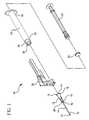
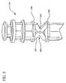
- FIG. 1is an exploded perspective view of the syringe assembly according to the present invention.
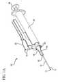
- FIG. 1Ais a perspective view of the syringe assembly according to the present invention.
- FIG. 2is a cross-sectional side elevation view of the syringe assembly of the present invention, with the plunger in position to perform an injection.
- FIG. 3is a cross-sectional side elevation view of the syringe assembly of FIG. 2 , with the plunger in position after an injection has been performed.
- FIG. 3Ais an enlarged cross-sectional side elevation view of the distal end of the syringe assembly of FIG. 3 .
- FIG. 4is a side elevation view of the plunger of FIG. 2 .
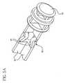
- FIG. 5is a perspective view of the plunger of FIG. 2 .
- FIG. 5Ais an enlarged perspective view of the contractible portion of the plunger of FIG. 5 .
- FIG. 6is a perspective view of a plunger according to another embodiment of the present invention.
- FIG. 6Ais an enlarged perspective view of the contractible portion of the plunger of FIG. 6 .
- FIG. 6Bis an enlarged perspective view of the distal portion of the plunger of FIG. 6 .
- FIG. 6Cis a partial cross-sectional side elevation view of the syringe assembly of FIG. 6 with the plunger in position to perform an injection.
- FIG. 7is a partial perspective view of the proximal portion of the plunger according to the present invention.
- FIG. 8is an enlarged perspective view of the distal end of a plunger according to still another embodiment of the invention.
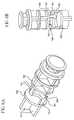
- FIG. 9is a cross sectional side elevation view of the safety shield of FIG. 1 .
- FIG. 9Ais a bottom plan view of the safety shield of FIG. 1
- FIG. 9Bis a side elevation view of the safety shield of FIG. 1 .
- FIG. 10is a bottom perspective view of the safety shield of FIG. 1 in its closed position.
- FIG. 11is a partial cross sectional view of the syringe assembly of FIG. 2 , after the plunger locking mechanism has been activated.
- FIG. 12is a perspective view of the syringe assembly according to the present invention, after the proximal portion of the plunger has been broken off.
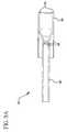
- FIG. 13is a partial cross sectional side elevation view of the syringe assembly of FIG. 6 , after the plunger locking mechanism has been activated.
- a syringe assembly 20generally comprises a barrel 22, a plunger 24, a needle assembly 26 and a safety shield assembly 28.
- Barrel 22includes a proximal end 30, a distal end 32, an inside surface 34, a fluid chamber 36 and an elongate tip 38 extending from distal end 32 having a passageway 40 therethrough in fluid communication with chamber 36.
- the barrelfurther includes a collar 42 around elongate tip 38 having a thread 43 on an inside surface 44 of the collar. This configuration is often referred to as a locking luer collar.
- the present inventioncontemplates the utilization of any type of syringe barrel and needle or needle assembly assembly, and not just a syringe having a locking luer collar.
- embodiments of the present inventionmay include an integral needle and syringe barrel, a luer slip tip with or without a collar, or any other needle/syringe configuration.
- a discontinuitysuch as locking projection 45 extends inwardly from the inside surface 34 of the barrel at its proximal end 30. As shown, the locking projection 45 is an annular ring. It is within the purview of the present invention for the discontinuity to have various shapes and configurations, including locking barbs, as long as the discontinuity locks the plunger in the barrel upon activation, as will be discussed below.
- Syringe assembly 20 of the present embodimentpreferably includes a needle assembly 26 having a cannula 11 having a proximal end 12, a distal end 13 and a lumen 14 therethrough.
- the needle assemblyfurther includes a hub 15 having an open proximal end 16 having a cavity 17 therein, and a distal end 18 joined to proximal end 12 of cannula 13 so that lumen 14 is in fluid communication with cavity 17.
- the hubincludes outwardly extending projections 19 and is placed on the distal end of barrel 22 by aligning the distal end of the barrel with the cavity in the hub so that the outward projections 19 of the hub engage thread 43 in the collar.
- Needle assembly 26is then rotated or screwed into the locking luer collar 42 so that the needle assembly is held tightly on the distal end 32 of the syringe barrel 22 through interaction of the locking luer collar thread 43 and the projections 19 on the needle hub and a frictional interference fit between elongate tip 38 on the barrel and cavity 17 in the hub.
- the lumen 14is in fluid communication with fluid chamber 36. It is within the purview of the present invention to include a needle assembly having one-piece construction wherein the cannula and the hub are formed of one piece and a cannula attached directly to the barrel without the use of a hub.
- Plunger 24includes an elongate body portion 46 having a proximal portion 48, a distal portion 50 and a stopper 52 disposed on the end of distal portion 50.
- Elongate body 46includes a plurality of outwardly projecting axial ribs 54.
- the plungerincludes four ribs, but may include fewer or more than four ribs.
- the plungerdefines contractible portion 56.
- the term contractible portion as used hereinshall include structure which is flexible, collapsible, breakable and/or deformable or the like.
- contractible portion 56is located along the distal portion of the plunger, but may be located anywhere along the plunger.
- the contractible portioncomprises flexing elements 57 disposed on each of the ribs.
- Each of the flexing elements in this embodimentcomprises a weakened portion of the rib that flexes or bends inwardly.
- Contractible portion 56 of the plungeris capable of withstanding the axial load of a typical injection. Application of an axial force greater than that required for a typical injection will result in the contractible portion of the plunger flexing deforming, breaking and/or collapsing, as will be discussed in greater detail below.
- the flexing elements 57 of this embodimentare strong enough to withstand the axial load of injection during normal use of a syringe.
- Plunger 24further includes a discontinuity such as annular locking ring 58 that is preferably located on proximal portion 48.
- the locking ringis preferably chamfered such that its diameter decreases in the distal direction.
- each ribOn the distal side of the locking ring 58, each rib preferably includes a slot 60.
- On the proximal side of the locking ring, each ribis configured to define a break point 62.
- the plungerincludes a thumb press 64.
- Stopper 52includes an inside surface 66 and an outside surface 68.
- the stopper 52fits over distal portion 50 of plunger 24 at an annular distal end 70 of the plunger.
- Inside surface 66 of the stopperincludes an annular groove 72 for receiving the annular distal end 70 of the plunger.
- Frictionmay also play a role in fitting the stopper onto the distal end of the plunger.
- the stopperfurther defines a cavity 74.
- the outside surface 68 of the stopperincludes at least one seal rib 76 for sealing engagement with inside surface 34 of barrel 22.
- the plungerfurther includes a distal shoulder 78 abutting the proximal end of stopper 52.
- FIG. 6 , 6A and 6Bshow an alternate embodiment of the invention where like parts are similarly numbered.
- a plunger 124includes a contractible portion 156 comprising a pair of platforms 159, each preferably having two pairs of flexing columns 157 extending therefrom and attaching to a flexing platform 161. The pairs of columns 157 are offset from each other preferably by 180 degrees.
- Flexing portion 156is capable of withstanding the axial load of a typical injection. Application of an axial force greater than that required for a typical injection will result in the contractible portion 156 of the plunger flexing, as will be discussed in greater detail below.
- FIG. 8shows yet another embodiment of a plunger 224 according to the present invention where like parts are similarly numbered.
- Plunger 224includes a contractible portion 256 comprising comprises two crossing flex members 257 connecting a pair of platforms 259.
- Contractible portion 256is capable of withstanding the axial load of a typical injection. Application of an axial force greater than that required for a typical injection will result in contractible portion 256 of the plunger flexing collapsing, breaking and/or deforming, as will be discussed in greater detail below. It is within the purview of the present invention to include plunger rods having different geometries, shapes and materials for the contractible portion.
- FIGS. 9 , 9A , 9B and 10show the safety shield 28.
- the safety shieldcomprises a hub 80 for engagement with collar 42 of barrel 22.
- Hub 80includes mating geometry on its inside surface that cooperates with an annular ring 82 on collar 42 of the barrel.
- the mating geometrymay be, for example an annular ring or a pair of projections extending from the inside surface of hub 80.
- the shieldattaches onto the collar via the hub in a snap fit arrangement. It is within the purview of this invention to provide for mating of the hub and collar other than a snap fit, such as an interference fit, threads, adhesive, welding, deformation and the like.
- the hubfurther includes edge 83 extending from its proximal end.
- Shield 28further comprises a hinge that preferably includes a living hinge such as hinge 84.
- Hinge 84connects the hub 80 to a shield member 86.
- Shield member 86includes proximal portion 88 and distal portion 90.
- the proximal portion 88includes locking members 92. Locking members 92 cooperate and latch onto ledge 83 when the safety shield is activated by moving it to the needle protecting position.
- Proximal portion 88is wide enough to receive needle hub 15, when the safety shield is activated.
- Distal portion 90 of the shield memberreceives and retains the needle cannula 11 when the safety shield is activated, that is, pivoted to its needle protecting position.
- Needle cannula 11is secured within the distal portion 90 of the shield member 86 by retaining members or arms 94 having free ends 95, preferably located on the interior surface of shield member 86.
- Retaining members 94allow for the needle cannula to pass therebetween while the shield member is rotated into activation, and are angled so that the needle is locked behind the retaining members once shield member 86 is fully activated and locked by locking members 92.
- the syringe assemblyincludes several features that can be used separately or in combination to ensure that syringe is used only a single time. Referring now to all of the figures, especially FIGS. 3 and 11 , the operation of the syringe assembly is described.
- the syringecan be filled from a vial, ampoule or other suitable container using known safe procedures.
- the syringeis filled by inserting the needle cannula into a vial and withdrawing the plunger 24. This will cause the liquid to be drawn through the lumen of the needle cannula and into fluid chamber 36.
- An important advantage of the present inventionis that the plunger can be moved back and forth along the barrel as many times as necessary to properly fill the fluid chamber.
- the syringe barrelmay be filled with sterile water and the sterile water can be injected into a vial contain lyophilized medication which is then drawn back into the syringe barrel.
- Contractible portion 56 of the plungeris strong enough to withstand the axial forces necessary for filling the syringe.
- Many single use syringes in the prior artonly allow one proximal motion of the plunger with respect to the barrel. With these prior art single use syringes, once the plunger is moved in a distal direction with respect to the barrel, it can no longer be withdrawn. Therefore, mixing sterile water and a lyophilized medication as described above is not possible.
- Fluid 37 in fluid chamber 36can now be injected into a patient or delivered in another suitable manner such as through the pierceable septum of a catheter connector. This occurs by applying an axial force to the thumb press 64 to cause plunger 24 to advance within barrel 22, thereby expelling the fluid through the lumen of needle cannula 11. The position of the plunger at the end of the injection is shown in FIG. 3 .
- FIG. 11shows the plunger in the locked position after the additional axial force C has been applied to the plunger.
- the additional axial forcecauses the flexing portions 57 to flex inwardly.
- the additional axial forcefurther causes locking ring 58 on the plunger to advance distally in the barrel past locking projection 45, in the barrel, as shown in FIG. 11 .
- the plungeris locked in the barrel and the syringe is disabled and unusable.
- the additional axial forcecan cause the stopper 52 to compress to allow for distal axial movement of the locking ring 58 into the locked position.
- the compression of the stopper 52allows the distal end 70 of the plunger to axially advance within the chamber 74 of the stopper 52. This, in turn, allows for axial travel of locking ring 58 in barrel 22 to a position beyond locking projection 45.
- the plunger 24, therefore,is locked in the barrel via the locking ring being advance beyond locking projection 45 of the barrel.
- the syringeis disabled and rendered unusable.
- An alternate embodiment of the inventionmay include a support pin on the distal end 70 of the plunger.
- the support pinwould support the stopper during an injection.
- the support pinmay pierce or puncture the stopper, if the compression of the stopper does not provide enough axial travel for the locking ring to lock.
- the present inventioncontemplates the use of contractible portion 56 of the plunger and the compressible stopper 52 either in combination or separately to achieve the axial travel required to lock the locking ring 58 in position beyond the locking projection 45.
- a plunger having a contractible portion 56 according to the present inventionmay be used in a two-piece syringe assembly, where there is no stopper and the plunger and the stopper are integrally formed, usually of the same material.
- the chamfer on locking ring 58provides the locking ring with a one directional stiffness feature.
- the chamferprovides more flexibility to the plunger locking ring while the plunger is axially advanced within the barrel 22, but less flexibility of the locking ring while the plunger is axially withdrawn from the barrel.
- Slots 60 located on the distal side of locking ring 58assist in achieving the one directional flexibility of the locking ring by acting as a flex point during axial advancement into the barrel. Since the slots have a minimal gap, the slots 60 only allow a minimal deflection when the plunger is being withdrawn from the barrel.
- the same one directional stiffnessmay be achieved through the presence of two thinner annular rings in place of the singe locking ring 58 and slots 60.
- the contractible portionhas enough stiffness to resist premature collapse during injection, but provide enough compliance of the plunger rod during activation to achieve the axial movement required to reach the final locked position.
- the axial force required for an injectionvaries based on the gauge and size of the needle and viscosity of fluid being injected.
- FIG. 13shows the plunger of the other embodiment of the invention illustrated in FIG. 6 , 6A and 6B in the locked configuration.
- application of an additional axial force C to the proximal end of the plungercauses flexing platform 161 to flex allowing for distal axial movement of locking ring 58 into barrel 22 of the syringe.
- Locking ring 58is locked in position via locking projection 45 on the barrel 22.
- plunger 124is locked into the barrel and the syringe is rendered disabled and unusable.
- application of an axial force in the proximal directionwill cause the proximal end of the plunger to break away, completely disabling the syringe, as shown in FIG. 12 .
- the additional force applied to the proximal end of the plungerwill result in the flexing cross members 257 compressing together so that platforms 259 move toward each other to allow for axial movement of the locking ring 58, thereby locking the plunger within the barrel and rendering the syringe unusable.
- the safety shield 26may be activated to shield the needle cannula and protect against accidental needle sticks.
- the safety shieldis activated by application a force in the direction of arrow D in FIG. 12 to the proximal portion 88 of the shield. This will activate the living hinge, causing the shield member 86 to rotate to the position shown in FIGS. 11 and 13 . Needle cannula 11 of the needle assembly is received between retaining members 94, and locking members 92 cooperate with the edge 83 to lock the shield in position.
- One advantage of the present inventionis the disabling features and safety shield may be activated with a single hand, further protecting the user.
- the present inventioncontemplates the use of several safety features, either alone or in combination.
- the safety featuresinclude a flexing plunger with a locking ring to lock the plunger within the barrel, a compressible stopper with a locking ring to lock the plunger within the barrel, a plunger having a proximal portion which breaks off, and a needle safety shield.
Landscapes
- Health & Medical Sciences (AREA)
- Engineering & Computer Science (AREA)
- Hematology (AREA)
- Anesthesiology (AREA)
- Biomedical Technology (AREA)
- Heart & Thoracic Surgery (AREA)
- Vascular Medicine (AREA)
- Life Sciences & Earth Sciences (AREA)
- Animal Behavior & Ethology (AREA)
- General Health & Medical Sciences (AREA)
- Public Health (AREA)
- Veterinary Medicine (AREA)
- Environmental & Geological Engineering (AREA)
- Infusion, Injection, And Reservoir Apparatuses (AREA)
Abstract
Description
- The present invention relates generally to single use syringes having safety features and more specifically to a single use syringe having a plunger locking mechanism and safety shield.
- In the United States and throughout the world, the multiple use of hypodermic syringe products that are intended for single use only, is instrumental in drug abuse and more particularly in the transfer of diseases. Intravenous drug users who routinely share and reuse syringes are a high-risk group with respect to the bloodbome pathogens including HIV and AIDS. Also the effects of multiple use are a major concern in underdeveloped countries where repeated use of syringe products may be responsible for the spread of many diseases. Reuse of single use hypodermic syringe assemblies is instrumental in the spread of drug abuse even in the absence of infection or disease.
- Many attempts have been made to remedy this problem. Some of these attempts have required a specific act to destroy the syringe after use either by using a destructive device or providing a syringe assembly with frangible zones so that the syringe could be rendered inoperable by application of force. Other attempts have involved the inclusion of structure which would allow the destruction or defeating of the syringe function through a conscious act by the syringe user. Although many of these devices work quite well, they do require the specific intent of the user followed by the actual act to destroy or render the syringe inoperable.
- Furthermore, in the medical arts, a syringe assembly typically includes a sharp pointed needle for administering fluids to patients either directly or into intravenous apparatus, and in various blood drawing applications either with syringes or with specialized holders for filling evacuated tubes. Since needles are widely used for medical procedures, many people can be exposed to needles in the routine course of their work.
- Accidental needle sticks from used hypodermic needles can transmit disease. Accordingly, various types of needle shields such as hinged needle shields, have been designed to reduce the possibility of accidental sticks.
- Various means have been provided for locking a hinged needle shield in the closed (needle protecting) position. Needles are available in a number of gauges and lengths so that they can be used for different purposes. Where a needle shield having a deflectable locking member is used to entrap a needle, it is important that the needle displaces the locking member or members as it enters the needle shield cavity. It is also important that, since the needle is entrapped by the deflectable locking member or members, it cannot easily be displaced from the cavity. A relatively large diameter needle can more easily displace a deflectable locking member than a small diameter needle, both entering the needle shield cavity and exiting the cavity. As a needle shield should preferably be usable to protect needles of various sizes, the deflectable locking member or members should be designed such that it is sufficiently flexible to allow even a relatively small diameter needle to deflect it as it enters the needle shield cavity, but provides sufficient resistance to prevent the needle from being re-exposed through the opening of the cavity.
- The first part of claim 1 refers to a single use syringe assembly of the type disclosed in
US 5,269,760 A . This syringe assembly comprises a barrel defining a chamber, a needle cannula, a plunger and means for locking the plunger in the barrel when applying an additional distally directed force to the plunger after fluid has been delivered from said chamber. The syringe barrel contains a reversible pawl that captures a locking dust cap provided at the proximal end of the plunger rod. Once the medicine is dispensed, the entire assembly locks completely shut, making retraction of the plunging assembly impossible. US 5,232,455 A discloses a syringe assembly comprising a barrel, a needle cannula and a plunger, wherein the barrel is connected with an elongate needle shield hingedly connected to the barrel. The needle shield has two side walls defining a longitudinal opening and a back wall. The needle shield is capable of pivoting from an open position wherein the needle cannula is exposed, to a closed needle protecting position wherein the distal end of the needle cannula is within the longitudinal opening of the shield.US 5,222,945 describes a safety syringe having a mechanism for locking the plunger within the barrel after use. A protective shield is slidably mounted on the barrel and is movable between an extended position and a retracted position. A re-use of the syringe is prevented by a plunger locking mechanism, which is engaged when the plunger is fully depressed.- It is an object of the invention to provide a single use syringe assembly having a re-use preventing function and is capable of protecting needles of various sizes.
- The single use syringe assembly of the invention is defined by Claim 1.
- The present invention is directed to a single use syringe having multiple safety features. These safety features include a plunger locking mechanism, which when activated, locks the plunger in the barrel so that the syringe may not be reused. The plunger locking mechanism includes a locking ring on the plunger and a locking projection near the proximal portion of the barrel. Alternatively, the plunger locking mechanism may include a pair of locking rings or discs. The plunger locking mechanism further includes either a flexible portion on the plunger or a compressible stopper. When an additional axial load or force is applied to the proximal end of the plunger, the flexible portion of the plunger flexes allowing the locking ring to axial displace itself beyond the locking projection, thereby locking the plunger within the barrel. Alternatively, if a compressible stopper is used, when an additional axial force is applied to the proximal end of the plunger, the stopper compresses, allowing the locking ring to axially displace itself beyond the locking projection of the barrel, thereby locking the plunger in the barrel. The flexible plunger and the compressible stopper may be used together. Alternatively, a syringe assembly may include only one of the flexible plunger or the compressible stopper.
- Another safety feature is a breakable proximal portion of the plunger. After the plunger has been locked within the barrel, if an attempt is made to withdraw the plunger from the barrel, the proximal portion will detach or break off from the plunger to ensure that the syringe is not reused.
- Yet another safety feature of the present invention is a hinged shield for shielding the needle cannula after an injection
- The present invention is advantageous because each of the safety features may be activated using a single hand. Another advantage of the present invention, is that conventional procedures for performing an injection may be utilized.
- A single use syringe of the present invention comprises a barrel including a cylindrical side wall having an inside surface defining a chamber for retaining fluid. The barrel includes an open proximal end and a distal end having a distal wall with an elongate tip extending distally therefrom having a passageway therethrough in fluid communication with the chamber. A needle cannula having a proximal end, a distal end and a lumen therethrough is connected to the elongate tip so that the lumen is in fluid communication with the passageway of the tip. The connection of the needle cannula to the tip can be either directly or indirectly through a hub attached to the needle cannula. An elongate needle shield is hingedly connected to the barrel. The needle shield includes two sidewalls defining a longitudinal opening and a back wall between the sidewalls defining a recess having an interior surface. The needle shield is capable of pivoting from an open position wherein the needle cannula is exposed, to a closed needle protecting position wherein the distal end of the needle cannula is within the longitudinal opening of the shield. A plunger including an elongate body portion having a proximal portion and a distal portion and a stopper is slidably positioned in fluid-tight engagement with the inside surface of the barrel for drawing fluid into and driving fluid out of the chamber by movement of the stopper relative to the barrel. The elongate body portion extends outwardly from the open proximal end of the barrel. The syringe assembly further includes means for locking the plunger in the barrel by applying an additional distally directed force to the plunger after fluid has been delivered from the chamber.
- The syringe assembly may also include plunger weakening structure for allowing the plunger to break upon application of excessive force intended to move the plunger proximally after the plunger has been locked in the barrel. This structure may take the form of a reduced cross-sectional thickness in the proximal portion of the elongate body portion of the plunger.
- Means for locking the plunger to the barrel may include a contractible portion on the plunger, a discontinuity on the plunger and a discontinuity on the barrel. The plunger discontinuity is capable of engaging the barrel discontinuity when an additional distally directed force which is applied to the plunger shortens the contractible portion so that the plunger discontinuity moves distally to engage the barrel discontinuity to lock the plunger in the barrel. The barrel discontinuity may be a recess or a projection and is preferably an inwardly directed projection in the shape of an annular ring. Likewise, discontinuity on the plunger may be a recess or a projection. The discontinuity is preferably an outwardly directed projection in the shape of an annular ring.
- The contractible portion of the plunger may include one or more flexible elements traversing a gap in the elongate body portion. The one or more elements are capable of withstanding the forces of fluid delivery and deflectable upon application of an additional force to the plunger. The contractible portion may also include a cavity formed by the distal end of the plunger and the interior surface of the stopper wherein the plunger moves into the cavity upon application of the additional force to effectively shorten the length of the plunger.
- The syringe assembly may further include structure for locking the needle shield in the closed needle protecting position when the needle shield is pivoted into the closed position. The needle shield locking structure may include an arm projecting from the interior surface of the needle shield. The arm includes a free end positioned so that when the needle shield is pivoted to the closed position, the needle cannula moves past the free end and is trapped in the needle shield by the arm. The needle shield locking structure may also include locking members on the proximal end of the needle shield capable of engaging a cooperating ledge at the distal end of the barrel when the needle shield is pivoted to the closed position.
- The syringe assembly may further include a needle assembly comprising the needle cannula and a hub having an open proximal end containing a cavity and a distal end attached to the proximal end of the cannula so that the lumen is in fluid communication with the cavity of the hub. The needle assembly is removably attached to the tip of the barrel by engagement of the tip in the cavity of the hub so that a lumen is in fluid communication with the chamber.
FIG. 1 is an exploded perspective view of the syringe assembly according to the present invention.FIG. 1A is a perspective view of the syringe assembly according to the present invention.FIG. 2 is a cross-sectional side elevation view of the syringe assembly of the present invention, with the plunger in position to perform an injection.FIG. 3 is a cross-sectional side elevation view of the syringe assembly ofFIG. 2 , with the plunger in position after an injection has been performed.FIG. 3A is an enlarged cross-sectional side elevation view of the distal end of the syringe assembly ofFIG. 3 .FIG. 4 is a side elevation view of the plunger ofFIG. 2 .FIG. 5 is a perspective view of the plunger ofFIG. 2 .FIG. 5A is an enlarged perspective view of the contractible portion of the plunger ofFIG. 5 .FIG. 6 is a perspective view of a plunger according to another embodiment of the present invention.FIG. 6A is an enlarged perspective view of the contractible portion of the plunger ofFIG. 6 .FIG. 6B is an enlarged perspective view of the distal portion of the plunger ofFIG. 6 .FIG. 6C is a partial cross-sectional side elevation view of the syringe assembly ofFIG. 6 with the plunger in position to perform an injection.FIG. 7 is a partial perspective view of the proximal portion of the plunger according to the present invention.FIG. 8 is an enlarged perspective view of the distal end of a plunger according to still another embodiment of the invention.FIG. 9 is a cross sectional side elevation view of the safety shield ofFIG. 1 .FIG. 9A is a bottom plan view of the safety shield ofFIG. 1 FIG. 9B is a side elevation view of the safety shield ofFIG. 1 .FIG. 10 is a bottom perspective view of the safety shield ofFIG. 1 in its closed position.FIG. 11 is a partial cross sectional view of the syringe assembly ofFIG. 2 , after the plunger locking mechanism has been activated.FIG. 12 is a perspective view of the syringe assembly according to the present invention, after the proximal portion of the plunger has been broken off.FIG. 13 is a partial cross sectional side elevation view of the syringe assembly ofFIG. 6 , after the plunger locking mechanism has been activated.- Referring to
FIGS. 1-5A , asyringe assembly 20 according to the present invention, generally comprises abarrel 22, aplunger 24, aneedle assembly 26 and asafety shield assembly 28. Barrel 22 includes aproximal end 30, adistal end 32, aninside surface 34, afluid chamber 36 and anelongate tip 38 extending fromdistal end 32 having apassageway 40 therethrough in fluid communication withchamber 36. The barrel further includes acollar 42 aroundelongate tip 38 having athread 43 on aninside surface 44 of the collar. This configuration is often referred to as a locking luer collar. The present invention contemplates the utilization of any type of syringe barrel and needle or needle assembly assembly, and not just a syringe having a locking luer collar. Thus, embodiments of the present invention may include an integral needle and syringe barrel, a luer slip tip with or without a collar, or any other needle/syringe configuration. A discontinuity such as lockingprojection 45 extends inwardly from theinside surface 34 of the barrel at itsproximal end 30. As shown, the lockingprojection 45 is an annular ring. It is within the purview of the present invention for the discontinuity to have various shapes and configurations, including locking barbs, as long as the discontinuity locks the plunger in the barrel upon activation, as will be discussed below.Syringe assembly 20 of the present embodiment preferably includes aneedle assembly 26 having acannula 11 having aproximal end 12, adistal end 13 and alumen 14 therethrough. The needle assembly further includes ahub 15 having an openproximal end 16 having a cavity 17 therein, and adistal end 18 joined toproximal end 12 ofcannula 13 so thatlumen 14 is in fluid communication with cavity 17. The hub includes outwardly extendingprojections 19 and is placed on the distal end ofbarrel 22 by aligning the distal end of the barrel with the cavity in the hub so that theoutward projections 19 of the hub engagethread 43 in the collar.Needle assembly 26 is then rotated or screwed into the lockingluer collar 42 so that the needle assembly is held tightly on thedistal end 32 of thesyringe barrel 22 through interaction of the lockingluer collar thread 43 and theprojections 19 on the needle hub and a frictional interference fit betweenelongate tip 38 on the barrel and cavity 17 in the hub. Thus, thelumen 14 is in fluid communication withfluid chamber 36. It is within the purview of the present invention to include a needle assembly having one-piece construction wherein the cannula and the hub are formed of one piece and a cannula attached directly to the barrel without the use of a hub.Plunger 24 includes anelongate body portion 46 having aproximal portion 48, adistal portion 50 and astopper 52 disposed on the end ofdistal portion 50.Elongate body 46 includes a plurality of outwardly projectingaxial ribs 54. Preferably, the plunger includes four ribs, but may include fewer or more than four ribs. According to the present invention, the plunger definescontractible portion 56. The term contractible portion as used herein shall include structure which is flexible, collapsible, breakable and/or deformable or the like. Preferablycontractible portion 56 is located along the distal portion of the plunger, but may be located anywhere along the plunger. In this embodiment, the contractible portion comprises flexingelements 57 disposed on each of the ribs. Each of the flexing elements in this embodiment, comprises a weakened portion of the rib that flexes or bends inwardly.Contractible portion 56 of the plunger is capable of withstanding the axial load of a typical injection. Application of an axial force greater than that required for a typical injection will result in the contractible portion of the plunger flexing deforming, breaking and/or collapsing, as will be discussed in greater detail below. Thus, the flexingelements 57 of this embodiment are strong enough to withstand the axial load of injection during normal use of a syringe.Plunger 24 further includes a discontinuity such asannular locking ring 58 that is preferably located onproximal portion 48. In this embodiment, the locking ring is preferably chamfered such that its diameter decreases in the distal direction. On the distal side of the lockingring 58, each rib preferably includes aslot 60. On the proximal side of the locking ring, each rib is configured to define abreak point 62. At its proximal end, the plunger includes athumb press 64.Stopper 52 includes aninside surface 66 and an outside surface 68. Thestopper 52 fits overdistal portion 50 ofplunger 24 at an annulardistal end 70 of the plunger. Insidesurface 66 of the stopper includes an annular groove 72 for receiving the annulardistal end 70 of the plunger. Thus, the stopper fits onto the plunger in a snap fit arrangement. Friction may also play a role in fitting the stopper onto the distal end of the plunger. The stopper further defines acavity 74. The outside surface 68 of the stopper includes at least oneseal rib 76 for sealing engagement withinside surface 34 ofbarrel 22. The plunger further includes adistal shoulder 78 abutting the proximal end ofstopper 52.FIG. 6 ,6A and 6B show an alternate embodiment of the invention where like parts are similarly numbered. Aplunger 124 includes acontractible portion 156 comprising a pair ofplatforms 159, each preferably having two pairs of flexingcolumns 157 extending therefrom and attaching to aflexing platform 161. The pairs ofcolumns 157 are offset from each other preferably by 180 degrees. Flexingportion 156 is capable of withstanding the axial load of a typical injection. Application of an axial force greater than that required for a typical injection will result in thecontractible portion 156 of the plunger flexing, as will be discussed in greater detail below.FIG. 8 shows yet another embodiment of aplunger 224 according to the present invention where like parts are similarly numbered.Plunger 224 includes acontractible portion 256 comprising comprises two crossingflex members 257 connecting a pair ofplatforms 259.Contractible portion 256 is capable of withstanding the axial load of a typical injection. Application of an axial force greater than that required for a typical injection will result incontractible portion 256 of the plunger flexing collapsing, breaking and/or deforming, as will be discussed in greater detail below. It is within the purview of the present invention to include plunger rods having different geometries, shapes and materials for the contractible portion.FIGS. 9 ,9A ,9B and10 show thesafety shield 28. The safety shield comprises ahub 80 for engagement withcollar 42 ofbarrel 22.Hub 80 includes mating geometry on its inside surface that cooperates with anannular ring 82 oncollar 42 of the barrel. The mating geometry may be, for example an annular ring or a pair of projections extending from the inside surface ofhub 80. Thus, the shield attaches onto the collar via the hub in a snap fit arrangement. It is within the purview of this invention to provide for mating of the hub and collar other than a snap fit, such as an interference fit, threads, adhesive, welding, deformation and the like.- The hub further includes
edge 83 extending from its proximal end.Shield 28 further comprises a hinge that preferably includes a living hinge such ashinge 84.Hinge 84 connects thehub 80 to ashield member 86.Shield member 86 includesproximal portion 88 and distal portion 90. Theproximal portion 88 includes lockingmembers 92. Lockingmembers 92 cooperate and latch ontoledge 83 when the safety shield is activated by moving it to the needle protecting position.Proximal portion 88 is wide enough to receiveneedle hub 15, when the safety shield is activated. - Distal portion 90 of the shield member receives and retains the
needle cannula 11 when the safety shield is activated, that is, pivoted to its needle protecting position.Needle cannula 11 is secured within the distal portion 90 of theshield member 86 by retaining members orarms 94 having free ends 95, preferably located on the interior surface ofshield member 86. Retainingmembers 94 allow for the needle cannula to pass therebetween while the shield member is rotated into activation, and are angled so that the needle is locked behind the retaining members onceshield member 86 is fully activated and locked by lockingmembers 92. - According to the present invention, the syringe assembly includes several features that can be used separately or in combination to ensure that syringe is used only a single time. Referring now to all of the figures, especially
FIGS. 3 and11 , the operation of the syringe assembly is described. In operation, the syringe can be filled from a vial, ampoule or other suitable container using known safe procedures. The syringe is filled by inserting the needle cannula into a vial and withdrawing theplunger 24. This will cause the liquid to be drawn through the lumen of the needle cannula and intofluid chamber 36. An important advantage of the present invention is that the plunger can be moved back and forth along the barrel as many times as necessary to properly fill the fluid chamber. For example, the syringe barrel may be filled with sterile water and the sterile water can be injected into a vial contain lyophilized medication which is then drawn back into the syringe barrel.Contractible portion 56 of the plunger is strong enough to withstand the axial forces necessary for filling the syringe. Many single use syringes in the prior art only allow one proximal motion of the plunger with respect to the barrel. With these prior art single use syringes, once the plunger is moved in a distal direction with respect to the barrel, it can no longer be withdrawn. Therefore, mixing sterile water and a lyophilized medication as described above is not possible. Fluid 37 influid chamber 36 can now be injected into a patient or delivered in another suitable manner such as through the pierceable septum of a catheter connector. This occurs by applying an axial force to thethumb press 64 to causeplunger 24 to advance withinbarrel 22, thereby expelling the fluid through the lumen ofneedle cannula 11. The position of the plunger at the end of the injection is shown inFIG. 3 .- Upon completion of the injection, an additional axial force indicated as C in
FIG. 3 is applied to the proximal portion of the plunger, preferably onthumb press 64.FIG. 11 shows the plunger in the locked position after the additional axial force C has been applied to the plunger. The additional axial force causes the flexingportions 57 to flex inwardly. As the flexing portions flex, the additional axial force further causes lockingring 58 on the plunger to advance distally in the barrel past lockingprojection 45, in the barrel, as shown inFIG. 11 . Thus, the plunger is locked in the barrel and the syringe is disabled and unusable. - In addition to or as an alternative to the action of the flexing portions, the additional axial force can cause the
stopper 52 to compress to allow for distal axial movement of the lockingring 58 into the locked position. The compression of thestopper 52 allows thedistal end 70 of the plunger to axially advance within thechamber 74 of thestopper 52. This, in turn, allows for axial travel of lockingring 58 inbarrel 22 to a position beyond lockingprojection 45. Theplunger 24, therefore, is locked in the barrel via the locking ring being advance beyond lockingprojection 45 of the barrel. Thus, the syringe is disabled and rendered unusable. - An alternate embodiment of the invention may include a support pin on the
distal end 70 of the plunger. The support pin would support the stopper during an injection. In addition, at the end of the injection, the support pin may pierce or puncture the stopper, if the compression of the stopper does not provide enough axial travel for the locking ring to lock. - The present invention contemplates the use of
contractible portion 56 of the plunger and thecompressible stopper 52 either in combination or separately to achieve the axial travel required to lock thelocking ring 58 in position beyond the lockingprojection 45. Thus, a plunger having acontractible portion 56 according to the present invention may be used in a two-piece syringe assembly, where there is no stopper and the plunger and the stopper are integrally formed, usually of the same material. - After locking
ring 58 is locked within the barrel viaannular locking projection 45, the plunger can no longer be withdrawn from the barrel. Any attempt to withdraw the plunger from the barrel will result in the proximal portion of the plunger breaking off. Application of an axial force to the plunger in the proximal direction will cause the proximal portion of the plunger to break off at breakingpoints 62, since the plunger is locked within the barrel, as shown inFIG. 12 . - The chamfer on locking
ring 58 provides the locking ring with a one directional stiffness feature. The chamfer provides more flexibility to the plunger locking ring while the plunger is axially advanced within thebarrel 22, but less flexibility of the locking ring while the plunger is axially withdrawn from the barrel.Slots 60 located on the distal side of lockingring 58 assist in achieving the one directional flexibility of the locking ring by acting as a flex point during axial advancement into the barrel. Since the slots have a minimal gap, theslots 60 only allow a minimal deflection when the plunger is being withdrawn from the barrel. In addition, the same one directional stiffness may be achieved through the presence of two thinner annular rings in place of thesinge locking ring 58 andslots 60. - As discussed, the contractible portion has enough stiffness to resist premature collapse during injection, but provide enough compliance of the plunger rod during activation to achieve the axial movement required to reach the final locked position. Of course, the axial force required for an injection varies based on the gauge and size of the needle and viscosity of fluid being injected.
FIG. 13 shows the plunger of the other embodiment of the invention illustrated inFIG. 6 ,6A and 6B in the locked configuration. In this embodiment, application of an additional axial force C to the proximal end of the plunger causes flexingplatform 161 to flex allowing for distal axial movement of lockingring 58 intobarrel 22 of the syringe. Lockingring 58 is locked in position via lockingprojection 45 on thebarrel 22. Thus,plunger 124 is locked into the barrel and the syringe is rendered disabled and unusable. After the plunger is locked, application of an axial force in the proximal direction will cause the proximal end of the plunger to break away, completely disabling the syringe, as shown inFIG. 12 .- According to the embodiment of the invention shown in
FIG. 8 , the additional force applied to the proximal end of the plunger will result in the flexingcross members 257 compressing together so thatplatforms 259 move toward each other to allow for axial movement of the lockingring 58, thereby locking the plunger within the barrel and rendering the syringe unusable. - After the syringe has been disabled, the
safety shield 26 may be activated to shield the needle cannula and protect against accidental needle sticks. The safety shield is activated by application a force in the direction of arrow D inFIG. 12 to theproximal portion 88 of the shield. This will activate the living hinge, causing theshield member 86 to rotate to the position shown inFIGS. 11 and13 .Needle cannula 11 of the needle assembly is received between retainingmembers 94, and lockingmembers 92 cooperate with theedge 83 to lock the shield in position. - One advantage of the present invention is the disabling features and safety shield may be activated with a single hand, further protecting the user.
- The present invention contemplates the use of several safety features, either alone or in combination. The safety features include a flexing plunger with a locking ring to lock the plunger within the barrel, a compressible stopper with a locking ring to lock the plunger within the barrel, a plunger having a proximal portion which breaks off, and a needle safety shield.
- Although the invention herein has been described with reference to particular embodiments, it is to be understood that these embodiments are merely illustrative of the principles and applications of the present invention. It is therefore to be understood that numerous modifications may be made to the illustrative embodiments and that other arrangements may be devised without departing from the scope of the present invention.
Claims (9)
- A single use syringe assembly comprising:a barrel (22) including a cylindrical side wall having an inside surface (34) defining a chamber (36) for retaining fluid, an open proximal end (30) and a distal end (32) including a distal wall with an elongate tip (38) extending distally therefrom having a passageway (40) therethrough in fluid communication with said chamber;a needle cannula (11) having a proximal end (12), a distal end (13) and a lumen (14) therethrough, said proximal end of said cannula being connected to said elongate tip (38) so that said lumen is in fluid communication with said passageway;a plunger (24; 124; 224) including an elongate body portion (46) having a proximal portion (48), a distal portion (50) and a stopper (52) slidably positioned in fluid-tight engagement with said inside surface (34) of said barrel for drawing fluid into and driving fluid out of said chamber (36) by movement of said stopper relative to said barrel, said elongate body portion (46) extending outwardly from said open proximal end of said barrel; andmeans for locking said plunger (24) in said barrel (22) when applying an additional distally directed force to said plunger after fluid has been delivered from said chamber,characterized by further comprising
an elongate needle shield (28) hingedly connected to said barrel (22), said needle shield having two side walls defining a longitudinal opening and a back wall between said side walls defining a recess having an interior surface, said needle shield capable of pivoting from an open position wherein said needle cannula is exposed, to a closed needle protecting position wherein said distal end of said needle cannula is within said longitudinal opening of said shield;
wherein said means for locking includes a contractible portion (56; 156; 256) on said plunger, a discontinuity (58) on said plunger, a discontinuity (45) on said barrel (22), said plunger discontinuity (58) capable of engaging said barrel discontinuity (45) when an additional distally directed force is applied to said plunger shortens said contractible portion (56) so that said plunger discontinuity moves distally to engage said barrel discontinuity to lock said plunger in said barrel. - The syringe assembly of claim 1 further including plunger weakening means (62) for allowing said plunger to break upon application of excessive force intended to move said plunger proximally after said plunger has been locked to said barrel.
- The syringe assembly of claim 1 wherein said contractible portion (56) of said plunger comprises one or more flexible elements (57) traversing a gap in said elongate body portion (46), said one or more elements capable of withstanding the forces of fluid delivery and deflectable upon application of said additional force.
- The syringe assembly of claim 1 wherein said contractible portion (56) on said plunger (24) includes a cavity (74) formed by a distal end (70) of said plunger and an interior surface of said stopper, said plunger moving into said cavity upon application of said additional force.
- The syringe assembly of claim 1 further including means (94) for locking said needle shield (28) in said closed needle protecting position when said needle shield is pivoted into said closed position.
- The syringe assembly of claim 5 wherein said locking means includes an arm (94) projecting from said interior surface of said needle shield, said arm having a free end positioned so that when said needle shield is pivoted to said closed position, said needle cannula moves past said free end and is trapped in said needle shield (28) by said arm.
- The syringe assembly of claim 6 wherein said locking means includes locking members (92) on a proximal end of said needle shield engaging cooperating ledge (83) at said distal end of said barrel when said needle shield is pivoted to said closed position.
- The syringe assembly of claim 2 wherein said weakening means (62) includes an area of reduced cross-sectional thickness in said proximal portion (48) of said elongate body portion (46) of said plunger.
- The syringe assembly of claim 1 further comprising a needle assembly (26) including said cannula (11) and a hub (15) having an open proximal end (12) containing a cavity (17) and a distal end (13) attached to said proximal end of said cannula so that said lumen (14) is in fluid communication with said cavity (17), said needle assembly being removably attached to said tip (38) of said barrel through engagement of said tip to said cavity so that said lumen (14) is in fluid communication with said chamber (36).
Priority Applications (1)
| Application Number | Priority Date | Filing Date | Title |
|---|---|---|---|
| SI200332118TSI1551482T1 (en) | 2002-10-11 | 2003-10-02 | Single use syringe having safety shield |
Applications Claiming Priority (3)
| Application Number | Priority Date | Filing Date | Title |
|---|---|---|---|
| US41805102P | 2002-10-11 | 2002-10-11 | |
| US418051P | 2002-10-11 | ||
| PCT/US2003/031249WO2004033008A1 (en) | 2002-10-11 | 2003-10-02 | Single use syringe having safety shield |
Publications (2)
| Publication Number | Publication Date |
|---|---|
| EP1551482A1 EP1551482A1 (en) | 2005-07-13 |
| EP1551482B1true EP1551482B1 (en) | 2011-12-14 |
Family
ID=32094140
Family Applications (1)
| Application Number | Title | Priority Date | Filing Date |
|---|---|---|---|
| EP03770615AExpired - LifetimeEP1551482B1 (en) | 2002-10-11 | 2003-10-02 | Single use syringe having safety shield |
Country Status (14)
| Country | Link |
|---|---|
| US (1) | US7387615B2 (en) |
| EP (1) | EP1551482B1 (en) |
| KR (1) | KR101075454B1 (en) |
| CN (1) | CN100430103C (en) |
| AT (1) | ATE536901T1 (en) |
| AU (2) | AU2003279104B2 (en) |
| BR (1) | BRPI0315217B8 (en) |
| DK (1) | DK1551482T3 (en) |
| ES (1) | ES2379254T3 (en) |
| MX (1) | MXPA05003837A (en) |
| RU (1) | RU2330687C2 (en) |
| SI (1) | SI1551482T1 (en) |
| WO (1) | WO2004033008A1 (en) |
| ZA (1) | ZA200503496B (en) |
Families Citing this family (49)
| Publication number | Priority date | Publication date | Assignee | Title |
|---|---|---|---|---|
| US8226617B2 (en) | 1999-11-04 | 2012-07-24 | Tyco Healthcare Group Lp | Safety shield apparatus and mounting structure for use with medical needle devices |
| US20050228479A1 (en)* | 2001-11-29 | 2005-10-13 | Cook Incorporated | Medical device delivery system |
| US7250038B2 (en)* | 2003-09-09 | 2007-07-31 | Smiths Medical Asd, Inc. | Fixed needle syringe with protective needle housing |
| WO2007032352A1 (en)* | 2005-09-13 | 2007-03-22 | Nipro Corporation | Safety syringe |
| US8038654B2 (en)* | 2007-02-26 | 2011-10-18 | Becton, Dickinson And Company | Syringe having a hinged needle shield |
| AU2007352135B2 (en)* | 2007-04-24 | 2011-09-29 | Morgan Meditech Inc | Single use syringe |
| DE102007026972A1 (en)* | 2007-06-04 | 2008-12-11 | Cet Consulting Engineering Trading Monika Eccard | Disposable syringe with reuse protection |
| US7972302B2 (en) | 2007-06-12 | 2011-07-05 | Becton, Dickinson And Company | Syringe with disabling mechanism |
| CN101808686B (en)* | 2007-06-12 | 2012-11-28 | 贝克顿·迪金森公司 | Syringe with disabling mechanism |
| US8361018B2 (en)* | 2007-06-12 | 2013-01-29 | Becton, Dickinson And Company | Syringe with disabling mechanism |
| JP2010533020A (en) | 2007-07-12 | 2010-10-21 | スター・シリンジ・リミテッド | Needle stick prevention device |
| USD617454S1 (en)* | 2008-02-13 | 2010-06-08 | Retractable Technologies, Inc. | Syringe barrel with divided petaloid tip |
| CN102159267B (en)* | 2008-09-18 | 2013-08-07 | 贝克顿·迪金森公司 | Container for injection device with injection needle |
| KR101702674B1 (en)* | 2008-11-26 | 2017-02-06 | 백톤 디킨슨 앤드 컴퍼니 | Single-use auto-disable syringe |
| USD617453S1 (en)* | 2008-12-15 | 2010-06-08 | Retractable Technologies, Inc. | Syringe barrel with divided petaloid tip |
| US8066668B2 (en)* | 2009-06-26 | 2011-11-29 | Becton, Dickinson And Company | Passive reuse prevention syringe that uses a flange lock |
| AU2013211572B2 (en)* | 2009-06-26 | 2015-06-11 | Becton, Dickinson And Company | Passive reuse prevention syringe that uses a flange lock |
| USD638538S1 (en)* | 2009-07-10 | 2011-05-24 | Becton, Dickinson And Company | Syringe plunger rod |
| EP2482872B2 (en)* | 2009-09-30 | 2019-12-11 | Sanofi-Aventis Deutschland GmbH | Method for assembling a drug delivery device, assembly for a drug delivery device and piston rod for a drug delivery device |
| EP2521582A1 (en)* | 2010-01-08 | 2012-11-14 | Amylin Pharmaceuticals, Inc. | Hypodermic needle assembly having a transition hub for enhancing fluid dynamics and microsphere injectability |
| JP2013517081A (en)* | 2010-01-19 | 2013-05-16 | ケンブリッジ・エンタープライズ・リミテッド | Apparatus and method |
| USD638539S1 (en) | 2010-02-22 | 2011-05-24 | Becton, Dickinson And Company | Needle hub |
| EP2585145B1 (en) | 2010-08-19 | 2014-03-05 | West Pharmaceutical Services, Inc. | Rigid needle shield |
| RU2584388C2 (en) | 2010-11-22 | 2016-05-20 | Б. Браун Мельзунген Аг | Hinged panel device and related methods |
| USD667107S1 (en)* | 2011-11-04 | 2012-09-11 | Becton, Dickinson And Company | Syringe plunger rod |
| USD667108S1 (en)* | 2011-11-04 | 2012-09-11 | Becton, Dickinson And Company | Syringe plunger rod |
| USD673268S1 (en)* | 2011-11-04 | 2012-12-25 | Becton, Dickinson And Company | Syringe plunger rod |
| USD673675S1 (en)* | 2011-11-04 | 2013-01-01 | Becton, Dickinson And Company | Syringe plunger rod |
| USD667109S1 (en)* | 2011-11-04 | 2012-09-11 | Becton, Dickinson And Company | Syringe plunger rod |
| US20130116628A1 (en)* | 2011-11-04 | 2013-05-09 | Becton, Dickinson And Company | Recycled Resin Compositions And Disposable Medical Devices Made Therefrom |
| US9278179B2 (en)* | 2012-06-20 | 2016-03-08 | Safety Syringes, Inc. | Contact trigger release needle guard with elastic spring |
| US8808239B2 (en)* | 2012-06-25 | 2014-08-19 | Kuo-Chi Hsu | Syringe |
| US8784376B2 (en) | 2012-12-04 | 2014-07-22 | Becton, Dickinson And Company | Thumb press frangible feature for re-use prevention |
| EP2752211A1 (en)* | 2013-01-07 | 2014-07-09 | F. Hoffmann-La Roche Ltd. | Safety device for an injection syringue |
| USD1010108S1 (en)* | 2013-03-15 | 2024-01-02 | Medtronic, Inc. | Plunger |
| US11311312B2 (en) | 2013-03-15 | 2022-04-26 | Medtronic, Inc. | Subcutaneous delivery tool |
| FR3004114B1 (en)* | 2013-04-03 | 2015-09-18 | Jacques Frette | SYRINGE AND NEEDLE AUTOBLOQUING SECURITY, DISPOSABLE. |
| USD1032834S1 (en) | 2014-03-11 | 2024-06-25 | Medtronic, Inc. | Plunger |
| US9867951B2 (en) | 2014-04-08 | 2018-01-16 | B. Braun Melsungen Ag | Hinged cap needle assemblies and related methods |
| US10029049B2 (en) | 2015-03-19 | 2018-07-24 | B. Braun Melsungen Ag | Hinged shield assemblies and related methods |
| KR101685689B1 (en) | 2015-06-11 | 2016-12-13 | (주)가이버 | Safety cap for disposable syringe |
| GB201616398D0 (en)* | 2016-09-27 | 2016-11-09 | Owen Mumford Ltd | Syringe plunger rod |
| CN110312541B (en)* | 2017-02-17 | 2022-05-31 | 贝克顿·迪金森公司 | Syringe and plunger rod with stopper guide |
| KR102089718B1 (en)* | 2017-10-11 | 2020-03-17 | 주식회사 밴드골드 | Safety sylinge |
| US11083847B2 (en) | 2018-01-26 | 2021-08-10 | Becton, Dickinson And Company | Flush syringe with flip cap |
| CN116212164A (en)* | 2018-03-20 | 2023-06-06 | 贝克顿·迪金森公司 | a plug |
| US20200282146A1 (en)* | 2019-03-09 | 2020-09-10 | Neo Mechanics Limited | Single-use syringe |
| CN111744077A (en)* | 2020-06-05 | 2020-10-09 | 王素荣 | Angina pectoris alleviating and treating device for cardiovascular internal medicine |
| JP2023023102A (en)* | 2021-08-04 | 2023-02-16 | ニプロ株式会社 | Injection needle protection member |
Family Cites Families (14)
| Publication number | Priority date | Publication date | Assignee | Title |
|---|---|---|---|---|
| US4775364A (en)* | 1987-07-10 | 1988-10-04 | Anthony Alles | Non re-useable disposable hypodermic syringe |
| US5019044A (en)* | 1989-08-14 | 1991-05-28 | Tsao Chien Hua | Safety hypodermic syringe |
| US5085640A (en)* | 1990-04-06 | 1992-02-04 | Gibbs Andrew H | Non-reusable medical needle apparatus |
| US5232455A (en)* | 1991-01-07 | 1993-08-03 | Smiths Industries Medical Systems, Inc. | Syringe with protective housing |
| US5106372A (en)* | 1991-05-03 | 1992-04-21 | Sherwood Medical Company | Single use syringe |
| US5269760A (en)* | 1991-11-14 | 1993-12-14 | Bina Dale C | Non-reusable hypodermic syringe |
| US5222945A (en)* | 1992-10-13 | 1993-06-29 | Basnight Robert W | Hypodermic syringe with protective shield |
| CN2216838Y (en)* | 1995-02-25 | 1996-01-10 | 陈士轩 | Safety cover for needle of infusion |
| US5769822A (en)* | 1996-09-13 | 1998-06-23 | Mcgary; R. Kern | Non-reusable retractable safety syringe |
| DE19705892C1 (en)* | 1997-02-15 | 1998-11-12 | Siekmann Gmbh | Universal safety syringe |
| US6217550B1 (en)* | 1998-07-29 | 2001-04-17 | Becton, Dickinson And Company | Single-use syringe |
| US6298541B1 (en)* | 1998-08-28 | 2001-10-09 | Becton, Dickinson And Company | Method for making a safety shield assembly and related combinations thereof |
| KR200166124Y1 (en)* | 1999-07-27 | 2000-02-15 | 방영철 | Safety syringe |
| US20020091361A1 (en)* | 1999-09-09 | 2002-07-11 | Rosoff Jack P. | Multiple-dose syringe |
- 2003
- 2003-10-02AUAU2003279104Apatent/AU2003279104B2/ennot_activeExpired
- 2003-10-02ESES03770615Tpatent/ES2379254T3/ennot_activeExpired - Lifetime
- 2003-10-02KRKR1020057006242Apatent/KR101075454B1/ennot_activeExpired - Lifetime
- 2003-10-02RURU2005114488/14Apatent/RU2330687C2/enactive
- 2003-10-02EPEP03770615Apatent/EP1551482B1/ennot_activeExpired - Lifetime
- 2003-10-02USUS10/530,847patent/US7387615B2/ennot_activeExpired - Lifetime
- 2003-10-02BRBRPI0315217Apatent/BRPI0315217B8/ennot_activeIP Right Cessation
- 2003-10-02SISI200332118Tpatent/SI1551482T1/enunknown
- 2003-10-02MXMXPA05003837Apatent/MXPA05003837A/enactiveIP Right Grant
- 2003-10-02CNCNB2003801039954Apatent/CN100430103C/ennot_activeExpired - Lifetime
- 2003-10-02ATAT03770615Tpatent/ATE536901T1/enactive
- 2003-10-02WOPCT/US2003/031249patent/WO2004033008A1/ennot_activeApplication Discontinuation
- 2003-10-02DKDK03770615.7Tpatent/DK1551482T3/enactive
- 2005
- 2005-05-03ZAZA200503496Apatent/ZA200503496B/enunknown
- 2010
- 2010-05-28AUAU2010202200Apatent/AU2010202200B2/ennot_activeExpired
Also Published As
| Publication number | Publication date |
|---|---|
| ES2379254T3 (en) | 2012-04-24 |
| AU2003279104A1 (en) | 2004-05-04 |
| BR0315217A (en) | 2005-08-16 |
| RU2005114488A (en) | 2006-02-27 |
| CN100430103C (en) | 2008-11-05 |
| AU2010202200B2 (en) | 2013-03-14 |
| CN1713932A (en) | 2005-12-28 |
| BRPI0315217B1 (en) | 2015-10-20 |
| WO2004033008A1 (en) | 2004-04-22 |
| SI1551482T1 (en) | 2012-04-30 |
| US20060052748A1 (en) | 2006-03-09 |
| KR20050048681A (en) | 2005-05-24 |
| ZA200503496B (en) | 2008-01-30 |
| US7387615B2 (en) | 2008-06-17 |
| AU2003279104B2 (en) | 2010-03-11 |
| ATE536901T1 (en) | 2011-12-15 |
| EP1551482A1 (en) | 2005-07-13 |
| KR101075454B1 (en) | 2011-10-24 |
| RU2330687C2 (en) | 2008-08-10 |
| BRPI0315217B8 (en) | 2021-06-22 |
| DK1551482T3 (en) | 2012-04-10 |
| AU2010202200A1 (en) | 2010-06-24 |
| MXPA05003837A (en) | 2005-06-22 |
Similar Documents
| Publication | Publication Date | Title |
|---|---|---|
| EP1551482B1 (en) | Single use syringe having safety shield | |
| US20230201483A1 (en) | Safety needle device | |
| EP0704225B1 (en) | Retractable needle syringe | |
| US5273543A (en) | Safety needle syringe | |
| CA2093386C (en) | Safety needle syringe | |
| RU2095090C1 (en) | Syringe for hypodermic injections | |
| EP0327061B1 (en) | Disposable retractable syringe | |
| US6626863B1 (en) | Safety syringe | |
| US20040030294A1 (en) | Retractable needle single use safety syringe | |
| EP1092443A2 (en) | Retracting needle syringe | |
| US20040097884A1 (en) | Single-use syringe | |
| WO1993006879A1 (en) | Retractable hypodermic syringe | |
| US20080154212A1 (en) | Syringe with retractable needle support | |
| US6562003B2 (en) | Safely disposable hypodermic syringe | |
| CN119136867A (en) | Safety device for syringes |
Legal Events
| Date | Code | Title | Description |
|---|---|---|---|
| PUAI | Public reference made under article 153(3) epc to a published international application that has entered the european phase | Free format text:ORIGINAL CODE: 0009012 | |
| 17P | Request for examination filed | Effective date:20050419 | |
| AK | Designated contracting states | Kind code of ref document:A1 Designated state(s):AT BE BG CH CY CZ DE DK EE ES FI FR GB GR HU IE IT LI LU MC NL PT RO SE SI SK TR | |
| AX | Request for extension of the european patent | Extension state:AL LT LV MK | |
| DAX | Request for extension of the european patent (deleted) | ||
| 17Q | First examination report despatched | Effective date:20100903 | |
| GRAP | Despatch of communication of intention to grant a patent | Free format text:ORIGINAL CODE: EPIDOSNIGR1 | |
| GRAS | Grant fee paid | Free format text:ORIGINAL CODE: EPIDOSNIGR3 | |
| GRAA | (expected) grant | Free format text:ORIGINAL CODE: 0009210 | |
| AK | Designated contracting states | Kind code of ref document:B1 Designated state(s):AT BE BG CH CY CZ DE DK EE ES FI FR GB GR HU IE IT LI LU MC NL PT RO SE SI SK TR | |
| REG | Reference to a national code | Ref country code:GB Ref legal event code:FG4D | |
| REG | Reference to a national code | Ref country code:CH Ref legal event code:EP | |
| REG | Reference to a national code | Ref country code:IE Ref legal event code:FG4D | |
| REG | Reference to a national code | Ref country code:CH Ref legal event code:NV Representative=s name:ISLER & PEDRAZZINI AG | |
| REG | Reference to a national code | Ref country code:DE Ref legal event code:R096 Ref document number:60339417 Country of ref document:DE Effective date:20120308 | |
| REG | Reference to a national code | Ref country code:SE Ref legal event code:TRGR | |
| REG | Reference to a national code | Ref country code:NL Ref legal event code:VDEP Effective date:20111214 | |
| REG | Reference to a national code | Ref country code:DK Ref legal event code:T3 | |
| REG | Reference to a national code | Ref country code:ES Ref legal event code:FG2A Ref document number:2379254 Country of ref document:ES Kind code of ref document:T3 Effective date:20120424 | |
| PG25 | Lapsed in a contracting state [announced via postgrant information from national office to epo] | Ref country code:NL Free format text:LAPSE BECAUSE OF FAILURE TO SUBMIT A TRANSLATION OF THE DESCRIPTION OR TO PAY THE FEE WITHIN THE PRESCRIBED TIME-LIMIT Effective date:20111214 Ref country code:GR Free format text:LAPSE BECAUSE OF FAILURE TO SUBMIT A TRANSLATION OF THE DESCRIPTION OR TO PAY THE FEE WITHIN THE PRESCRIBED TIME-LIMIT Effective date:20120315 | |
| PG25 | Lapsed in a contracting state [announced via postgrant information from national office to epo] | Ref country code:CY Free format text:LAPSE BECAUSE OF FAILURE TO SUBMIT A TRANSLATION OF THE DESCRIPTION OR TO PAY THE FEE WITHIN THE PRESCRIBED TIME-LIMIT Effective date:20111214 | |
| PG25 | Lapsed in a contracting state [announced via postgrant information from national office to epo] | Ref country code:SK Free format text:LAPSE BECAUSE OF FAILURE TO SUBMIT A TRANSLATION OF THE DESCRIPTION OR TO PAY THE FEE WITHIN THE PRESCRIBED TIME-LIMIT Effective date:20111214 Ref country code:CZ Free format text:LAPSE BECAUSE OF FAILURE TO SUBMIT A TRANSLATION OF THE DESCRIPTION OR TO PAY THE FEE WITHIN THE PRESCRIBED TIME-LIMIT Effective date:20111214 Ref country code:EE Free format text:LAPSE BECAUSE OF FAILURE TO SUBMIT A TRANSLATION OF THE DESCRIPTION OR TO PAY THE FEE WITHIN THE PRESCRIBED TIME-LIMIT Effective date:20111214 Ref country code:BG Free format text:LAPSE BECAUSE OF FAILURE TO SUBMIT A TRANSLATION OF THE DESCRIPTION OR TO PAY THE FEE WITHIN THE PRESCRIBED TIME-LIMIT Effective date:20120314 | |
| PG25 | Lapsed in a contracting state [announced via postgrant information from national office to epo] | Ref country code:RO Free format text:LAPSE BECAUSE OF FAILURE TO SUBMIT A TRANSLATION OF THE DESCRIPTION OR TO PAY THE FEE WITHIN THE PRESCRIBED TIME-LIMIT Effective date:20111214 Ref country code:PT Free format text:LAPSE BECAUSE OF FAILURE TO SUBMIT A TRANSLATION OF THE DESCRIPTION OR TO PAY THE FEE WITHIN THE PRESCRIBED TIME-LIMIT Effective date:20120416 | |
| PLBE | No opposition filed within time limit | Free format text:ORIGINAL CODE: 0009261 | |
| STAA | Information on the status of an ep patent application or granted ep patent | Free format text:STATUS: NO OPPOSITION FILED WITHIN TIME LIMIT | |
| 26N | No opposition filed | Effective date:20120917 | |
| REG | Reference to a national code | Ref country code:DE Ref legal event code:R097 Ref document number:60339417 Country of ref document:DE Effective date:20120917 | |
| PG25 | Lapsed in a contracting state [announced via postgrant information from national office to epo] | Ref country code:MC Free format text:LAPSE BECAUSE OF NON-PAYMENT OF DUE FEES Effective date:20121031 | |
| PG25 | Lapsed in a contracting state [announced via postgrant information from national office to epo] | Ref country code:FI Free format text:LAPSE BECAUSE OF FAILURE TO SUBMIT A TRANSLATION OF THE DESCRIPTION OR TO PAY THE FEE WITHIN THE PRESCRIBED TIME-LIMIT Effective date:20111214 | |
| PG25 | Lapsed in a contracting state [announced via postgrant information from national office to epo] | Ref country code:TR Free format text:LAPSE BECAUSE OF FAILURE TO SUBMIT A TRANSLATION OF THE DESCRIPTION OR TO PAY THE FEE WITHIN THE PRESCRIBED TIME-LIMIT Effective date:20111214 | |
| PG25 | Lapsed in a contracting state [announced via postgrant information from national office to epo] | Ref country code:LU Free format text:LAPSE BECAUSE OF NON-PAYMENT OF DUE FEES Effective date:20121002 | |
| PG25 | Lapsed in a contracting state [announced via postgrant information from national office to epo] | Ref country code:HU Free format text:LAPSE BECAUSE OF FAILURE TO SUBMIT A TRANSLATION OF THE DESCRIPTION OR TO PAY THE FEE WITHIN THE PRESCRIBED TIME-LIMIT Effective date:20031002 | |
| REG | Reference to a national code | Ref country code:FR Ref legal event code:PLFP Year of fee payment:14 | |
| REG | Reference to a national code | Ref country code:FR Ref legal event code:PLFP Year of fee payment:15 | |
| REG | Reference to a national code | Ref country code:FR Ref legal event code:PLFP Year of fee payment:16 | |
| PGFP | Annual fee paid to national office [announced via postgrant information from national office to epo] | Ref country code:SE Payment date:20220920 Year of fee payment:20 Ref country code:IE Payment date:20220921 Year of fee payment:20 Ref country code:GB Payment date:20220922 Year of fee payment:20 Ref country code:DK Payment date:20220920 Year of fee payment:20 | |
| PGFP | Annual fee paid to national office [announced via postgrant information from national office to epo] | Ref country code:FR Payment date:20220921 Year of fee payment:20 Ref country code:BE Payment date:20220920 Year of fee payment:20 | |
| PGFP | Annual fee paid to national office [announced via postgrant information from national office to epo] | Ref country code:IT Payment date:20220920 Year of fee payment:20 Ref country code:ES Payment date:20221102 Year of fee payment:20 Ref country code:DE Payment date:20220616 Year of fee payment:20 Ref country code:AT Payment date:20220921 Year of fee payment:20 | |
| PGFP | Annual fee paid to national office [announced via postgrant information from national office to epo] | Ref country code:SI Payment date:20220928 Year of fee payment:20 Ref country code:CH Payment date:20221101 Year of fee payment:20 | |
| REG | Reference to a national code | Ref country code:DE Ref legal event code:R071 Ref document number:60339417 Country of ref document:DE | |
| REG | Reference to a national code | Ref country code:DK Ref legal event code:EUP Expiry date:20231002 | |
| REG | Reference to a national code | Ref country code:CH Ref legal event code:PL | |
| REG | Reference to a national code | Ref country code:BE Ref legal event code:MK Effective date:20231002 | |
| REG | Reference to a national code | Ref country code:GB Ref legal event code:PE20 Expiry date:20231001 | |
| REG | Reference to a national code | Ref country code:ES Ref legal event code:FD2A Effective date:20231027 | |
| PG25 | Lapsed in a contracting state [announced via postgrant information from national office to epo] | Ref country code:GB Free format text:LAPSE BECAUSE OF EXPIRATION OF PROTECTION Effective date:20231001 | |
| REG | Reference to a national code | Ref country code:AT Ref legal event code:MK07 Ref document number:536901 Country of ref document:AT Kind code of ref document:T Effective date:20231002 | |
| REG | Reference to a national code | Ref country code:SE Ref legal event code:EUG | |
| PG25 | Lapsed in a contracting state [announced via postgrant information from national office to epo] | Ref country code:SI Free format text:LAPSE BECAUSE OF EXPIRATION OF PROTECTION Effective date:20231003 | |
| REG | Reference to a national code | Ref country code:IE Ref legal event code:MK9A | |
| PG25 | Lapsed in a contracting state [announced via postgrant information from national office to epo] | Ref country code:ES Free format text:LAPSE BECAUSE OF EXPIRATION OF PROTECTION Effective date:20231003 | |
| PG25 | Lapsed in a contracting state [announced via postgrant information from national office to epo] | Ref country code:IE Free format text:LAPSE BECAUSE OF EXPIRATION OF PROTECTION Effective date:20231002 Ref country code:ES Free format text:LAPSE BECAUSE OF EXPIRATION OF PROTECTION Effective date:20231003 |