EP1551308B1 - Introduction system for minimally invasive surgical instruments - Google Patents
Introduction system for minimally invasive surgical instrumentsDownload PDFInfo
- Publication number
- EP1551308B1 EP1551308B1EP03808072AEP03808072AEP1551308B1EP 1551308 B1EP1551308 B1EP 1551308B1EP 03808072 AEP03808072 AEP 03808072AEP 03808072 AEP03808072 AEP 03808072AEP 1551308 B1EP1551308 B1EP 1551308B1
- Authority
- EP
- European Patent Office
- Prior art keywords
- confirmation device
- target confirmation
- introducer
- target
- cannula
- Prior art date
- Legal status (The legal status is an assumption and is not a legal conclusion. Google has not performed a legal analysis and makes no representation as to the accuracy of the status listed.)
- Expired - Lifetime
Links
- 238000012790confirmationMethods0.000claimsabstractdescription40
- 238000003780insertionMethods0.000claimsabstractdescription10
- 230000037431insertionEffects0.000claimsabstractdescription10
- 238000001574biopsyMethods0.000claimsdescription42
- 239000012530fluidSubstances0.000claimsdescription22
- 238000002595magnetic resonance imagingMethods0.000claimsdescription20
- 239000000463materialSubstances0.000claimsdescription19
- 230000008685targetingEffects0.000claimsdescription10
- 229940030225antihemorrhagicsDrugs0.000claimsdescription5
- 206010002091AnaesthesiaDiseases0.000claimsdescription3
- 230000037005anaesthesiaEffects0.000claimsdescription3
- 230000000025haemostatic effectEffects0.000claimsdescription3
- 238000003384imaging methodMethods0.000claimsdescription3
- 239000003550markerSubstances0.000claimsdescription3
- 238000004891communicationMethods0.000claimsdescription2
- 239000002874hemostatic agentSubstances0.000claims1
- 238000000034methodMethods0.000abstractdescription8
- 239000008280bloodSubstances0.000description5
- 210000004369bloodAnatomy0.000description5
- FAPWRFPIFSIZLT-UHFFFAOYSA-MSodium chlorideChemical compound[Na+].[Cl-]FAPWRFPIFSIZLT-UHFFFAOYSA-M0.000description4
- 230000037361pathwayEffects0.000description4
- 238000011282treatmentMethods0.000description4
- 238000002059diagnostic imagingMethods0.000description3
- 239000011347resinSubstances0.000description3
- 229920005989resinPolymers0.000description3
- 239000011780sodium chlorideSubstances0.000description3
- 229940035674anestheticsDrugs0.000description2
- 238000013461designMethods0.000description2
- 239000003193general anesthetic agentSubstances0.000description2
- 229910001119inconels 625Inorganic materials0.000description2
- 230000003902lesionEffects0.000description2
- 238000012800visualizationMethods0.000description2
- 229910000619316 stainless steelInorganic materials0.000description1
- 241001631457CannulaSpecies0.000description1
- 102000008186CollagenHuman genes0.000description1
- 108010035532CollagenProteins0.000description1
- 206010028980NeoplasmDiseases0.000description1
- RTAQQCXQSZGOHL-UHFFFAOYSA-NTitaniumChemical compound[Ti]RTAQQCXQSZGOHL-UHFFFAOYSA-N0.000description1
- 238000013459approachMethods0.000description1
- 230000000740bleeding effectEffects0.000description1
- 229920001436collagenPolymers0.000description1
- 238000002405diagnostic procedureMethods0.000description1
- 230000001747exhibiting effectEffects0.000description1
- 239000011521glassSubstances0.000description1
- 238000002324minimally invasive surgeryMethods0.000description1
- 230000035515penetrationEffects0.000description1
- 229910052719titaniumInorganic materials0.000description1
- 239000010936titaniumSubstances0.000description1
Images


Classifications
- A—HUMAN NECESSITIES
- A61—MEDICAL OR VETERINARY SCIENCE; HYGIENE
- A61B—DIAGNOSIS; SURGERY; IDENTIFICATION
- A61B10/00—Instruments for taking body samples for diagnostic purposes; Other methods or instruments for diagnosis, e.g. for vaccination diagnosis, sex determination or ovulation-period determination; Throat striking implements
- A61B10/02—Instruments for taking cell samples or for biopsy
- A61B10/0233—Pointed or sharp biopsy instruments
- A61B10/0266—Pointed or sharp biopsy instruments means for severing sample
- A61B10/0275—Pointed or sharp biopsy instruments means for severing sample with sample notch, e.g. on the side of inner stylet
- A—HUMAN NECESSITIES
- A61—MEDICAL OR VETERINARY SCIENCE; HYGIENE
- A61B—DIAGNOSIS; SURGERY; IDENTIFICATION
- A61B17/00—Surgical instruments, devices or methods
- A61B17/34—Trocars; Puncturing needles
- A61B17/3403—Needle locating or guiding means
- A—HUMAN NECESSITIES
- A61—MEDICAL OR VETERINARY SCIENCE; HYGIENE
- A61B—DIAGNOSIS; SURGERY; IDENTIFICATION
- A61B10/00—Instruments for taking body samples for diagnostic purposes; Other methods or instruments for diagnosis, e.g. for vaccination diagnosis, sex determination or ovulation-period determination; Throat striking implements
- A61B10/02—Instruments for taking cell samples or for biopsy
- A61B10/0233—Pointed or sharp biopsy instruments
- A61B10/0283—Pointed or sharp biopsy instruments with vacuum aspiration, e.g. caused by retractable plunger or by connected syringe
- A—HUMAN NECESSITIES
- A61—MEDICAL OR VETERINARY SCIENCE; HYGIENE
- A61B—DIAGNOSIS; SURGERY; IDENTIFICATION
- A61B90/00—Instruments, implements or accessories specially adapted for surgery or diagnosis and not covered by any of the groups A61B1/00 - A61B50/00, e.g. for luxation treatment or for protecting wound edges
- A61B90/39—Markers, e.g. radio-opaque or breast lesions markers
- A61B2090/3904—Markers, e.g. radio-opaque or breast lesions markers specially adapted for marking specified tissue
- A61B2090/3908—Soft tissue, e.g. breast tissue
- A—HUMAN NECESSITIES
- A61—MEDICAL OR VETERINARY SCIENCE; HYGIENE
- A61B—DIAGNOSIS; SURGERY; IDENTIFICATION
- A61B90/00—Instruments, implements or accessories specially adapted for surgery or diagnosis and not covered by any of the groups A61B1/00 - A61B50/00, e.g. for luxation treatment or for protecting wound edges
- A61B90/39—Markers, e.g. radio-opaque or breast lesions markers
- A61B2090/3954—Markers, e.g. radio-opaque or breast lesions markers magnetic, e.g. NMR or MRI
- A—HUMAN NECESSITIES
- A61—MEDICAL OR VETERINARY SCIENCE; HYGIENE
- A61M—DEVICES FOR INTRODUCING MEDIA INTO, OR ONTO, THE BODY; DEVICES FOR TRANSDUCING BODY MEDIA OR FOR TAKING MEDIA FROM THE BODY; DEVICES FOR PRODUCING OR ENDING SLEEP OR STUPOR
- A61M1/00—Suction or pumping devices for medical purposes; Devices for carrying-off, for treatment of, or for carrying-over, body-liquids; Drainage systems
- A61M1/71—Suction drainage systems
- A61M1/77—Suction-irrigation systems
- A61M1/774—Handpieces specially adapted for providing suction as well as irrigation, either simultaneously or independently
Definitions
- the present inventionrelates to the field of medical devices and more particularly to a medical system for introducing, among other things, minimally invasive surgical instruments and other medical treatments into a patient's body.
- tissue biopsy devicesIn the field of tissue biopsy, minimally invasive biopsy devices have been developed that require only a single insertion point into a patient's body to remove one or more tissue samples.
- One such biopsy deviceincorporates a "tube-within-a-tube" design that includes an outer piercing needle having a sharpened distal end and a lateral opening that defines a tissue receiving port.
- An inner cutting memberis slidingly received within the outer piercing needle, which serves to excise tissue that has prolapsed into the tissue receiving port.
- a vacuumis used to draw the excised tissue into the tissue receiving port and aspirates the excised tissue from the biopsy site once severed.
- Exemplary "tube-within-a-tube” biopsy devicesare disclosed in pending U.S. Patent Applications, Serial Nos. 09/707,022 published as US 6,758,824 and 09/864,031 published as US 2002-0082519 A1 , which are owned by the assignee of the present invention.
- the exemplary biopsy devicescan be used in conjunction with Magnetic Resonance Imaging (MRI). This compatibility is due to the fact that many of the components of the biopsy devices are made of materials that do not interfere with operation of MRI apparatus or are otherwise compatible therewith. It is desirable to perform biopsies in conjunction with MRI because it is currently the only non-invasive visualization modality capable of defining the margins of a tumor.
- MRIMagnetic Resonance Imaging
- an MRI compatible medical introduction systemis desirable for use with minimally invasive biopsy devices, such as those employing a "tube-within-a-tube" design.
- FIG. 1is a side view of an introducer stylet according to an embodiment of the present invention
- FIG. 2is side view of an outer cannula and fluid conduit according to an embodiment of the present invention
- FIG. 3is a side view of a target confirmation device according to an embodiment of the present invention.
- FIGS. 3A and 3Bare side views of a target confirmation device according to alternate embodiments of the present invention.
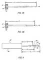
- FIG. 4is a side view of an exemplary biopsy device for use with the introduction system of the present invention.
- FIG. 5is a detailed cross-sectional view of a cutting element of the biopsy device of FIG. 4 ;
- FIG. 6is a side view of an aspiration wand suitable for insertion into the outer cannula.
- FIGS. 7-11are elevational views illustrating a medical procedure using the medical system of the present invention.
- a medical system 20that includes an introducer stylet 22, an outer cannula 24 and a target confirmation device 26.
- system 20is particularly, but not necessarily, suited for use in biopsy procedures that identify the target biopsy site using Magnetic Resonance Imaging (MRI) or comparable medical imaging modality.
- MRIMagnetic Resonance Imaging
- introducer stylet 22includes a handle 28 and a stylet 30 having a distal end 32 and a proximal end 34 connected to handle 28.
- Handle 28may be made of a medical grade resin or other MRI compatible material.
- Stylet 30may also be made of an MRI compatible, medical grade material, such as 316 stainless steel or inconel 625.
- a distal end 32 of stylet 30includes a tissue piercing tip, such as a trocar tip, to facilitate penetration of stylet 30 into a patient's tissue.
- tissue piercing tipsuch as a trocar tip
- stylet 30may include other devices for of piercing the patient's tissue, including without limitation, devices that use a laser or radio frequencies (RF) to pierce the tissue.
- RFradio frequencies
- outer cannula 24extends from an open proximal end 36 to an open distal end 38, which is separated from proximal end 36 by a distance "B."
- outer cannula 24may be made from a medical grade resin or other MRI compatible material.
- proximal end 36may include a luer-style fitting or other suitable configuration for interfacing, but not necessarily connecting, outer cannula 24 with target confirmation device 26.
- a depth limiting member 39such as a rubber o-ring, may be moveably disposed on outer cannula 24 to limit the insertion depth of outer cannula 24 into the patient's body.
- outer cannula 24also includes an inner lumen 40 therethrough, which is open to communication with a fluid conduit 42 for supplying fluids, such as saline and anesthetics, or removing fluids, such as blood, from the patient's body.
- Fluid conduit 42communicates with inner lumen 40 via a port in outer cannula 24.
- outer cannula 24may include a haemostatic valve, depicted generally as element 41, or a manually operable valve 41' that can be selectively closed to prevent the escape of fluid from proximal end 36.
- Fluid conduit 42may also include a directional valve 43 to selectively control the supply and removal of fluid to and from inner lumen 40, respectively.
- target confirmation device 26is an elongated member that is sized to fit within inner lumen 40 of outer cannula 24.
- Target confirmation device 26which may be made of a medical grade resin or other MRI compatible material, extends from a connecting end 44 to a distal end 46.
- Connecting end 44may be configured with a cap 47 that abuts outer cannula 24.
- cap 47may include a luer-style fitting or other suitable feature for interfacing, but not necessarily connecting, target confirmation device 26 with outer cannula 24.
- Distal end 46 of target confirmation device 26is generally rounded to facilitate entry into the patient's body.
- a portion of target confirmation device 26is configured with a magnetic resonance imaging (MRI) identifiable material, such as inconel 625, titanium or other material with similar magnetic characteristics.
- MRImagnetic resonance imaging
- a targeting band 48is provided a distance "C" from connecting end 44, as shown in FIG. 3 ; the distance C being measured from the approximate center of targeting band 48 to connecting end 44 (or the inside of cap 47), for example.
- Targeting band 48provides a reference point in an MR image relative to the target biopsy tissue.
- the tip of target confirmation deviceitself may be used to provide the reference point in the MR image, provided the target confirmation device material exhibits a relatively low artifact during MR imaging.
- artifactdescribes a material's tendency to distort an MR image A material exhibiting a relatively high artifact will render the body tissue surrounding the material unreadable in an MR image. Conversely, a material with a relatively low artifact will allow the material to be readily identified in the MR image and will not significantly distort the MR image of the surrounding tissue.
- the distal end 46 of target confirmation device 26may include a particular shape to help identify the location of target confirmation device 26 relative to the surrounding tissue.
- portion of target confirmation device 26 adj acent the distal end 46has a smaller diameter relative to the remaining length.
- a portion of target confirmation device 26is tapered to provide an hour glass like image when viewed under MR. It will be appreciated that the embodiments represented in FIGS. 3A and 3B are not limited to the configurations shown, and that other configurations are with in the scope of the present invention.
- introducer stylet 30may function as a target confirmation device.
- introducer stylet 30, and more particularly stylet 30,may be made of an MRI compatible material that preferably, but not necessarily, exhibits a relatively low artifact.
- FIG. 4An exemplary biopsy apparatus 50, which is suitable for use with medical system 20 of the present invention, is generally shown in FIG. 4 and in more detail in FIG 5 .
- Apparatus 50includes a cutting element 52 sized for introduction into the patient's body and a hand piece 54.
- the exemplary biopsy apparatus 50is configured as a "tube-within-a-tube" cutting device. More particularly, cutting element 52 includes an outer cannula 56 having an outer lumen 57 and an inner cannula 58 sized to fit concentrically within the outer lumen.
- a motor or other motion generating deviceis provided within hand piece 54 to rotate and/or translate inner cannula 58 within outer cannula 56.
- Biopsy apparatus similar to apparatus 50can be seen by way of example in the documents already cited on the first page.
- outer cannula 56defines a tissue-receiving opening 60, which communicates with outer lumen 57.
- the working end of cutting element 52further includes a cutting board 64 that is disposed within outer lumen 57 at the distal end of outer cannula 56.
- Inner cannula 58defines an inner lumen 65 that is hollow along its entire length to provide for aspiration of the biopsy sample (tissue).
- Inner cannula 58terminates in a cutting edge 66 that may be formed by an inwardly beveled surface having a razor-sharp edge.
- an aspirating wand 68is shown that can be inserted into outer cannula 24.
- aspirating wand 68extends from a connecting end 70 to an insertion end 72 and includes an inner lumen 74 that extends from connecting end 70 to insertion end 72.
- Connecting end 70may include a luer interface or other suitable fitting for connecting aspirating wand 68 to a vacuum source (not shown).
- Aspirating wand 68may also include a cap 76 that can be placed onto connecting end 70 to inhibit fluid leakage when aspirating wand 68 is inserted into the patient.
- the haemostatic valve 41 in outer cannula 24seals against aspirating wand 68, as it does against target confirmation device 26 and biopsy device 50, when inserted into outer cannula 24. Additionally, the outside diameter of aspirating wand 68 is less than the inside diameter of inner lumen 40 to allow saline or other fluids introduced through fluid conduit 40 to pass into the patient's body. When cap 76 is removed and aspirating wand 68 is connected to a vacuum source, fluids, such as blood and saline, can be aspirated from the biopsy site.
- system 20is employed to conduct a biopsy of a lesion within a patient's body.
- the target tissue or lesion to be biopsied and/or removed from the patient's body(denoted generally by mass 80 in FIG. 7 ) is located using a medical imaging system, such as MRI or other suitable imaging modality.
- a reference structure 82may be positioned adjacent the patient to assist in locating the target tissue. The location of the target tissue 80 relative to reference structure 82 may be determined along one or more axis.
- the target tissue location relative to reference structure 82is determined along the X and Y axes; however, the target tissue location may also be determined along all three of the X, Y and Z axes. While the described method employs a reference structure 82 to locate the target tissue, the reference structure is not necessarily required and a more "free-hand" approach may be utilized.
- reference structure 82includes a support grid having a number of holes therethrough. Each hole is sized to allow passage of outer cannula 24. The hole through which outer cannula 24 is ultimately inserted is determined by the location of target tissue 80 relative to reference structure 82 along the X and Y axes. The patient and reference structure 82 are viewed using a medical imaging system, such as MRI, to determine the location of the target tissue relative to reference structure 82.
- MRImagnetic resonance imaging system
- introducer stylet 22 and a portion of outer cannula 24are inserted through the support grid and into the patient's body, creating a pathway 84 to the target tissue 80 (see, e.g., FIG. 7 ).
- Introducer stylet 22is then removed from the patient's body leaving behind outer cannula 24 (see, e.g., FIG. 8 ).
- Fluidsmay be inserted into or removed from the patient's body through inner lumen 40 via fluid conduit 42. These fluids may include, for example, additional anesthetics and/or saline solution to cleanse pathway 84 and remove blood. Accumulated blood and other fluids within pathway 84 may be aspirated through fluid conduit 42 or by inserting aspirating wand 68 prior to insertion of target confirmation device 26.
- target confirmation device 26may be inserted into the patient's body through the port created by outer cannula 24 (see, e.g., FIGS. 8 and 9 ). With target confirmation device 26 properly inserted into outer cannula 24, an image of the target site is again taken to determine the location of targeting band 48 in relation to the target tissue and reference structure 82. If targeting band 48 is in the desired position adjacent target tissue 80 along the Z-axis, targeting device 26 is removed from outer cannula 24. However, if targeting band 48 is not in the desired position, then the position of target confirmation device 26 and outer cannula 24 is modified along the Z-axis until the desired position is achieved.
- depth limiting member 39is moved against reference structure 82 to inhibit movement of outer cannula 24 further into the patient.
- depth limiting membermay be moved directly against the patient's skin.
- Target confirmation device 26is then removed from outer cannula 24 and biopsy device 50 is inserted into outer cannula 24 until handpiece 54 abuts proximal end 36 of outer cannula 24.
- one or more samples of target tissue 80are removed from the patient through tissue-receiving opening 60.
- the correct position of tissue-receiving opening 60is ensured because the distance "C" between proximal end 44 of target confirmation device 26 and targeting band 48 (see, e.g., FIGS. 3 and 9 ), or the distance between proximal end 44 and the predetermined location on target confirmation device 26 ( FIGS. 3A and 3B ), is approximately equal to the distance between the center of tissue receiving opening 60 and handpiece 54 of biopsy device 50.
- the biopsy sitecan be aspirated using aspirating wand 68 (see, e.g., FIG. 11 ). During or after aspiration, a final image of the biopsy site can be taken to confirm removal of the target tissue. Finally, an MRI identifiable marker, such as a collagen plug, or other medical treatment can be inserted into the biopsy site through outer cannula 24.
- the medical system of the present inventionlocalizes the target biopsy site in a manner that allows confirmation of the target biopsy site under MRI or other visualization modality, and allows positioning of a biopsy device to ensure the cutting element of the biopsy device can be accurately placed at the target biopsy site.
- the medical system of the present inventionalso facilitates the introduction and removal of fluids from the target site, including without limitation, anesthesia and blood, but minimizes the exposure of the fluids to the adjacent equipment and medical staff.
- the medical systemprovides access to the target site to introduce a medical treatment, such as a site marker, tamponade or other haemostatic agent, after removal of the tissue.
Landscapes
- Health & Medical Sciences (AREA)
- Life Sciences & Earth Sciences (AREA)
- Surgery (AREA)
- General Health & Medical Sciences (AREA)
- Veterinary Medicine (AREA)
- Heart & Thoracic Surgery (AREA)
- Medical Informatics (AREA)
- Molecular Biology (AREA)
- Engineering & Computer Science (AREA)
- Animal Behavior & Ethology (AREA)
- Pathology (AREA)
- Public Health (AREA)
- Biomedical Technology (AREA)
- Nuclear Medicine, Radiotherapy & Molecular Imaging (AREA)
- Magnetic Resonance Imaging Apparatus (AREA)
- Surgical Instruments (AREA)
- Fluid-Driven Valves (AREA)
- Sampling And Sample Adjustment (AREA)
- Farming Of Fish And Shellfish (AREA)
- Endoscopes (AREA)
Abstract
Description
- The present invention relates to the field of medical devices and more particularly to a medical system for introducing, among other things, minimally invasive surgical instruments and other medical treatments into a patient's body.
- Medical procedures have advanced to stages where less invasive or minimally invasive surgeries, diagnostic procedures and exploratory procedures have become desired and demanded by patients, physicians, and various medical industry administrators. To meet these demands, improved medical devices and instrumentation have been developed, such as cannulas or micro-cannulas, medical introducers, vacuum assisted biopsy apparatus, and other endoscopic related devices.
- In the field of tissue biopsy, minimally invasive biopsy devices have been developed that require only a single insertion point into a patient's body to remove one or more tissue samples. One such biopsy device incorporates a "tube-within-a-tube" design that includes an outer piercing needle having a sharpened distal end and a lateral opening that defines a tissue receiving port. An inner cutting member is slidingly received within the outer piercing needle, which serves to excise tissue that has prolapsed into the tissue receiving port. A vacuum is used to draw the excised tissue into the tissue receiving port and aspirates the excised tissue from the biopsy site once severed.
- Exemplary "tube-within-a-tube" biopsy devices are disclosed in pending
U.S. Patent Applications, Serial Nos. 09/707,022 published asUS 6,758,824 and09/864,031 US 2002-0082519 A1 , which are owned by the assignee of the present invention. Among other features, the exemplary biopsy devices can be used in conjunction with Magnetic Resonance Imaging (MRI). This compatibility is due to the fact that many of the components of the biopsy devices are made of materials that do not interfere with operation of MRI apparatus or are otherwise compatible therewith. It is desirable to perform biopsies in conjunction with MRI because it is currently the only non-invasive visualization modality capable of defining the margins of a tumor. - While the exemplary MRI compatible biopsy devices have proven effective in operation, in some procedures it is desirable to create a pathway to the biopsy site for precise introduction of the biopsy device and other medical treatments into the patient. For these and other reasons, an MRI compatible medical introduction system is desirable for use with minimally invasive biopsy devices, such as those employing a "tube-within-a-tube" design.
- Document
WO 98/22022 A1 - Embodiments of the invention will now be described, by way of example, with reference to the accompanying drawings, wherein:
FIG. 1 is a side view of an introducer stylet according to an embodiment of the present invention;FIG. 2 is side view of an outer cannula and fluid conduit according to an embodiment of the present invention;FIG. 3 is a side view of a target confirmation device according to an embodiment of the present invention;FIGS. 3A and 3B are side views of a target confirmation device according to alternate embodiments of the present invention;FIG. 4 is a side view of an exemplary biopsy device for use with the introduction system of the present invention;FIG. 5 is a detailed cross-sectional view of a cutting element of the biopsy device ofFIG. 4 ;FIG. 6 is a side view of an aspiration wand suitable for insertion into the outer cannula; andFIGS. 7-11 are elevational views illustrating a medical procedure using the medical system of the present invention.- Referring now to the drawings, the preferred illustrative embodiments of the present invention are shown in detail. Although the drawings represent some preferred embodiments of the present invention, the drawings are not necessarily to scale and certain features may be exaggerated to better illustrate and explain the present invention. Further, the embodiments set forth herein are not intended to be exhaustive or otherwise limit or restrict the invention to the precise forms and configurations shown in the drawings and disclosed in the following detailed description.
- Referring to
FIGS. 1-3 , amedical system 20 is shown that includes anintroducer stylet 22, anouter cannula 24 and atarget confirmation device 26. As will be described in detail,system 20 is particularly, but not necessarily, suited for use in biopsy procedures that identify the target biopsy site using Magnetic Resonance Imaging (MRI) or comparable medical imaging modality. - In an embodiment, introducer
stylet 22 includes ahandle 28 and astylet 30 having adistal end 32 and aproximal end 34 connected to handle 28.Handle 28 may be made of a medical grade resin or other MRI compatible material.Stylet 30 may also be made of an MRI compatible, medical grade material, such as 316 stainless steel or inconel 625. - In a particular configuration, a
distal end 32 ofstylet 30 includes a tissue piercing tip, such as a trocar tip, to facilitate penetration ofstylet 30 into a patient's tissue. In addition to a trocar tip, it will be appreciated thatstylet 30 may include other devices for of piercing the patient's tissue, including without limitation, devices that use a laser or radio frequencies (RF) to pierce the tissue. The length ofstylet 30 is generally denoted by the reference character "A" inFIG. 1 . - Referring to the embodiment shown in
FIG. 2 ,outer cannula 24 extends from an openproximal end 36 to an opendistal end 38, which is separated fromproximal end 36 by a distance "B." Like introducerstylet 30,outer cannula 24 may be made from a medical grade resin or other MRI compatible material. In some configurations,proximal end 36 may include a luer-style fitting or other suitable configuration for interfacing, but not necessarily connecting,outer cannula 24 withtarget confirmation device 26. Adepth limiting member 39, such as a rubber o-ring, may be moveably disposed onouter cannula 24 to limit the insertion depth ofouter cannula 24 into the patient's body. - In an embodiment,
outer cannula 24 also includes aninner lumen 40 therethrough, which is open to communication with afluid conduit 42 for supplying fluids, such as saline and anesthetics, or removing fluids, such as blood, from the patient's body.Fluid conduit 42 communicates withinner lumen 40 via a port inouter cannula 24. In some configurations,outer cannula 24 may include a haemostatic valve, depicted generally aselement 41, or a manually operable valve 41' that can be selectively closed to prevent the escape of fluid fromproximal end 36.Fluid conduit 42 may also include adirectional valve 43 to selectively control the supply and removal of fluid to and frominner lumen 40, respectively. - In the embodiment shown in
FIG. 3 ,target confirmation device 26 is an elongated member that is sized to fit withininner lumen 40 ofouter cannula 24.Target confirmation device 26, which may be made of a medical grade resin or other MRI compatible material, extends from a connectingend 44 to adistal end 46. Connectingend 44 may be configured with acap 47 that abutsouter cannula 24. In some configurations,cap 47 may include a luer-style fitting or other suitable feature for interfacing, but not necessarily connecting,target confirmation device 26 withouter cannula 24. Distal end 46 oftarget confirmation device 26 is generally rounded to facilitate entry into the patient's body. In an embodiment, a portion oftarget confirmation device 26 is configured with a magnetic resonance imaging (MRI) identifiable material, such as inconel 625, titanium or other material with similar magnetic characteristics. In one particular configuration, atargeting band 48 is provided a distance "C" from connectingend 44, as shown inFIG. 3 ; the distance C being measured from the approximate center of targetingband 48 to connecting end 44 (or the inside of cap 47), for example.Targeting band 48 provides a reference point in an MR image relative to the target biopsy tissue.- In another embodiment of the present invention, the tip of target confirmation device itself may be used to provide the reference point in the MR image, provided the target confirmation device material exhibits a relatively low artifact during MR imaging. As used herein, the term "artifact" describes a material's tendency to distort an MR image A material exhibiting a relatively high artifact will render the body tissue surrounding the material unreadable in an MR image. Conversely, a material with a relatively low artifact will allow the material to be readily identified in the MR image and will not significantly distort the MR image of the surrounding tissue.
- As shown in the embodiments of
FIGS. 3A and 3B , thedistal end 46 oftarget confirmation device 26 may include a particular shape to help identify the location oftarget confirmation device 26 relative to the surrounding tissue. In the embodiment ofFIG. 3A , portion oftarget confirmation device 26 adj acent thedistal end 46 has a smaller diameter relative to the remaining length. In the embodiment ofFIG. 3B , a portion oftarget confirmation device 26 is tapered to provide an hour glass like image when viewed under MR. It will be appreciated that the embodiments represented inFIGS. 3A and 3B are not limited to the configurations shown, and that other configurations are with in the scope of the present invention. - In still another embodiment,
introducer stylet 30 may function as a target confirmation device. In this embodiment,introducer stylet 30, and more particularlystylet 30, may be made of an MRI compatible material that preferably, but not necessarily, exhibits a relatively low artifact. - An
exemplary biopsy apparatus 50, which is suitable for use withmedical system 20 of the present invention, is generally shown inFIG. 4 and in more detail inFIG 5 .Apparatus 50 includes a cuttingelement 52 sized for introduction into the patient's body and ahand piece 54. Theexemplary biopsy apparatus 50 is configured as a "tube-within-a-tube" cutting device. More particularly, cuttingelement 52 includes anouter cannula 56 having anouter lumen 57 and aninner cannula 58 sized to fit concentrically within the outer lumen. A motor or other motion generating device is provided withinhand piece 54 to rotate and/or translateinner cannula 58 withinouter cannula 56. Biopsy apparatus similar toapparatus 50 can be seen by way of example in the documents already cited on the first page. - A particular embodiment of the working end of cutting
element 52 is depicted inFIG. 5 . In the illustrated embodiment,outer cannula 56 defines a tissue-receivingopening 60, which communicates withouter lumen 57. The working end of cuttingelement 52 further includes a cuttingboard 64 that is disposed withinouter lumen 57 at the distal end ofouter cannula 56.Inner cannula 58 defines aninner lumen 65 that is hollow along its entire length to provide for aspiration of the biopsy sample (tissue).Inner cannula 58 terminates in acutting edge 66 that may be formed by an inwardly beveled surface having a razor-sharp edge. - Referring to
FIG. 6 , an aspiratingwand 68 is shown that can be inserted intoouter cannula 24. In an embodiment, aspiratingwand 68 extends from a connectingend 70 to aninsertion end 72 and includes aninner lumen 74 that extends from connectingend 70 toinsertion end 72. Connectingend 70 may include a luer interface or other suitable fitting for connecting aspiratingwand 68 to a vacuum source (not shown). Aspiratingwand 68 may also include acap 76 that can be placed onto connectingend 70 to inhibit fluid leakage when aspiratingwand 68 is inserted into the patient. Thehaemostatic valve 41 inouter cannula 24 seals against aspiratingwand 68, as it does againsttarget confirmation device 26 andbiopsy device 50, when inserted intoouter cannula 24. Additionally, the outside diameter of aspiratingwand 68 is less than the inside diameter ofinner lumen 40 to allow saline or other fluids introduced throughfluid conduit 40 to pass into the patient's body. Whencap 76 is removed and aspiratingwand 68 is connected to a vacuum source, fluids, such as blood and saline, can be aspirated from the biopsy site. - Referring to
FIGS. 7-11 , a medicalprocedure using system 20 of the present invention will be described. In an embodiment,system 20 is employed to conduct a biopsy of a lesion within a patient's body. The target tissue or lesion to be biopsied and/or removed from the patient's body (denoted generally bymass 80 inFIG. 7 ) is located using a medical imaging system, such as MRI or other suitable imaging modality. Areference structure 82 may be positioned adjacent the patient to assist in locating the target tissue. The location of thetarget tissue 80 relative to referencestructure 82 may be determined along one or more axis. In the illustrated embodiment, the target tissue location relative to referencestructure 82 is determined along the X and Y axes; however, the target tissue location may also be determined along all three of the X, Y and Z axes. While the described method employs areference structure 82 to locate the target tissue, the reference structure is not necessarily required and a more "free-hand" approach may be utilized. - In an embodiment,
reference structure 82 includes a support grid having a number of holes therethrough. Each hole is sized to allow passage ofouter cannula 24. The hole through whichouter cannula 24 is ultimately inserted is determined by the location oftarget tissue 80 relative to referencestructure 82 along the X and Y axes. The patient andreference structure 82 are viewed using a medical imaging system, such as MRI, to determine the location of the target tissue relative to referencestructure 82. - After application of anesthesia, the stylet portion of
introducer stylet 22 and a portion ofouter cannula 24 are inserted through the support grid and into the patient's body, creating apathway 84 to the target tissue 80 (see, e.g.,FIG. 7 ).Introducer stylet 22 is then removed from the patient's body leaving behind outer cannula 24 (see, e.g.,FIG. 8 ). - Fluids may be inserted into or removed from the patient's body through
inner lumen 40 viafluid conduit 42. These fluids may include, for example, additional anesthetics and/or saline solution to cleansepathway 84 and remove blood. Accumulated blood and other fluids withinpathway 84 may be aspirated throughfluid conduit 42 or by inserting aspiratingwand 68 prior to insertion oftarget confirmation device 26. - Once
introducer stylet 22 is removed fromouter cannula 24,target confirmation device 26 may be inserted into the patient's body through the port created by outer cannula 24 (see, e.g.,FIGS. 8 and9 ). Withtarget confirmation device 26 properly inserted intoouter cannula 24, an image of the target site is again taken to determine the location of targetingband 48 in relation to the target tissue andreference structure 82. If targetingband 48 is in the desired positionadjacent target tissue 80 along the Z-axis, targetingdevice 26 is removed fromouter cannula 24. However, if targetingband 48 is not in the desired position, then the position oftarget confirmation device 26 andouter cannula 24 is modified along the Z-axis until the desired position is achieved. - Once the desired position is achieved,
depth limiting member 39 is moved againstreference structure 82 to inhibit movement ofouter cannula 24 further into the patient. When noreference structure 82 is used, depth limiting member may be moved directly against the patient's skin.Target confirmation device 26 is then removed fromouter cannula 24 andbiopsy device 50 is inserted intoouter cannula 24 untilhandpiece 54 abutsproximal end 36 ofouter cannula 24. In the embodiment illustrated inFIG. 10 , one or more samples oftarget tissue 80 are removed from the patient through tissue-receivingopening 60. The correct position of tissue-receivingopening 60 is ensured because the distance "C" betweenproximal end 44 oftarget confirmation device 26 and targeting band 48 (see, e.g.,FIGS. 3 and9 ), or the distance betweenproximal end 44 and the predetermined location on target confirmation device 26 (FIGS. 3A and 3B ), is approximately equal to the distance between the center oftissue receiving opening 60 andhandpiece 54 ofbiopsy device 50. - After completion of the biopsy, the biopsy site can be aspirated using aspirating wand 68 (see, e.g.,
FIG. 11 ). During or after aspiration, a final image of the biopsy site can be taken to confirm removal of the target tissue. Finally, an MRI identifiable marker, such as a collagen plug, or other medical treatment can be inserted into the biopsy site throughouter cannula 24. - Among other features, the medical system of the present invention localizes the target biopsy site in a manner that allows confirmation of the target biopsy site under MRI or other visualization modality, and allows positioning of a biopsy device to ensure the cutting element of the biopsy device can be accurately placed at the target biopsy site. The medical system of the present invention also facilitates the introduction and removal of fluids from the target site, including without limitation, anesthesia and blood, but minimizes the exposure of the fluids to the adjacent equipment and medical staff. In addition to allowing the medical staff to identify the presence of significant bleeding and to introduce a biopsy device into the patient, the medical system provides access to the target site to introduce a medical treatment, such as a site marker, tamponade or other haemostatic agent, after removal of the tissue.
- The present invention has been particularly shown and described with reference to the foregoing embodiments, which are merely illustrative of the best modes for carrying out the invention. It should be understood by those skilled in the art that various alternatives to the embodiments of the invention described herein may be employed in practicing the invention without departing from the scope of the invention as defined in the following claims. It is intended that the following claims define the scope of the invention and that the apparatus within the scope of these claims and their equivalents be covered thereby. This description of the invention should be understood to include all novel and non-obvious combinations of elements described herein, and claims may be presented in this or a later application to any novel and non-obvious combination of these elements. Moreover, the foregoing embodiments are illustrative.
Claims (19)
- A medical system, comprising:an introducer cannula (24);an introducer stylet (22) removably disposed within the introducer cannula (24) and configured for insertion into a patient's body proximate a target site (80);a target confirmation device (26) removably insertable within the introducer cannula (24), the target confirmation device (26) having an imaging means identifiable material for confirming the position of the introducer cannula (24) relative to the target site (80);characterized in thatthe system further comprises a biopsy device (50) insertable within the introducer cannula (24),the biopsy device (50) includes an outer cannula (56) having an outer lumen, and an inner cannula (5) which fits substantially concentrically within the outer lumen (57).
- The system of claim 1, wherein the introducer cannula (24) is configured to introduce at least one of a site marker, an anesthesia, a fluid, a tamponade, and a hemostatic agent.
- The system of claim 1, wherein the introducer stylet (22) is the target confirmation device (26).
- The system of claim 1, wherein the target confirmation device (26) includes a magnetic resonance imaging (MRI) identifiable material (48).
- The system of claim 4, wherein the magnetic resonance imaging (MRI) identifiable material (48) is a band (48) disposed proximate a distal end (46) of the target confirmation device (26).
- The system of claim 1, wherein the system (20) is magnetic resonance imaging (MRI) compatible.
- The system of claim 1, wherein the magnetic resonance imaging (MRI) identifiable material (48) is shaped to distinguish the target confirmation device (26) from the patient's tissue (80).
- The system of claim 1, wherein a distal end of the introducer stylet (22) includes a tissue piercing member (32).
- The system of claim 1, wherein the introducer cannula (24) includes an inner lumen (40) and a fluid conduit (42) provided in communication with the inner lumen (40).
- The system of claim 1, wherein the fluid conduit (42) includes a directional valve (43).
- The system of claim 1, wherein the target confirmation device (26) includes a proximal end (44) having a first fitting interface (47) that engages a second fitting interface (36) on the introducer cannula (24) upon insertion of the target confirmation device (26) into the introducer cannula (24).
- The system of claim 1, wherein the introducer cannula (24) includes a haemostatic valve (41).
- The system of claim 1, wherein the target confirmation device (26) includes a relatively low artifact generating material.
- The system of claim 1, wherein the biopsy device (50) includes a handpiece (54) and a cutting element (52), the cutting element (52) defining a tissue-receiving opening (60) for removing tissue from the target site (80).
- The system of claim 1, wherein the distance between a proximal end (44) and a distal end (46) of the target confirmation device (26) is approximately equal to the distance between the center of the tissue receiving opening (60) and the handpiece (54) of the biopsy device (50).
- The system of claim 1, wherein the target confirmation device (26) includes a targeting band (48).
- The system of claim 16, wherein the distance between a proximal end (44) of the target confirmation device (26) and the targeting band (48) is approximately equal to the distance between the center of the tissue receiving opening (60) and the handpiece (54) of the biopsy device (50).
- The system of claim 14, wherein the length of the cutting element (52) is approximately equal to the length of the introducer stylet (22).
- The system of claim 14, wherein the length of the target confirmation device (26) is approximately equal to the length of the introducer stylet (22).
Applications Claiming Priority (5)
| Application Number | Priority Date | Filing Date | Title |
|---|---|---|---|
| US41675502P | 2002-10-07 | 2002-10-07 | |
| US416755P | 2002-10-07 | ||
| US10/649,068US7347829B2 (en) | 2002-10-07 | 2003-08-27 | Introduction system for minimally invasive surgical instruments |
| US649068 | 2003-08-27 | ||
| PCT/US2003/026958WO2004032749A1 (en) | 2002-10-07 | 2003-08-28 | Introduction system for minimally invasive surgical instruments |
Publications (2)
| Publication Number | Publication Date |
|---|---|
| EP1551308A1 EP1551308A1 (en) | 2005-07-13 |
| EP1551308B1true EP1551308B1 (en) | 2010-10-27 |
Family
ID=32096161
Family Applications (1)
| Application Number | Title | Priority Date | Filing Date |
|---|---|---|---|
| EP03808072AExpired - LifetimeEP1551308B1 (en) | 2002-10-07 | 2003-08-28 | Introduction system for minimally invasive surgical instruments |
Country Status (7)
| Country | Link |
|---|---|
| US (1) | US7347829B2 (en) |
| EP (1) | EP1551308B1 (en) |
| JP (1) | JP4460531B2 (en) |
| AT (1) | ATE485773T1 (en) |
| AU (1) | AU2003260121A1 (en) |
| DE (1) | DE60334716D1 (en) |
| WO (1) | WO2004032749A1 (en) |
Families Citing this family (103)
| Publication number | Priority date | Publication date | Assignee | Title |
|---|---|---|---|---|
| EP1524940B1 (en) | 2002-03-19 | 2011-08-24 | Bard Dublin ITC Limited | Biopsy device and biopsy needle module that can be inserted into the biopsy device |
| US8109885B2 (en) | 2002-03-19 | 2012-02-07 | C. R. Bard, Inc. | Biopsy device for removing tissue specimens using a vacuum |
| US20070260267A1 (en)* | 2002-10-07 | 2007-11-08 | Nicoson Zachary R | Localizing obturator |
| US8123698B2 (en)* | 2002-10-07 | 2012-02-28 | Suros Surgical Systems, Inc. | System and method for minimally invasive disease therapy |
| US20080161720A1 (en)* | 2002-10-07 | 2008-07-03 | Nicoson Zachary R | Registration system |
| DE20305093U1 (en) | 2003-03-29 | 2003-09-11 | Heske, Norbert F., 82288 Kottgeisering | Coaxial cannula with sealing element |
| DE10314240B4 (en)* | 2003-03-29 | 2025-05-28 | Bard Dublin Itc Ltd. | Pressure generation unit |
| US8172770B2 (en)* | 2005-09-28 | 2012-05-08 | Suros Surgical Systems, Inc. | System and method for minimally invasive disease therapy |
| US20120289859A9 (en)* | 2003-08-27 | 2012-11-15 | Nicoson Zachary R | System and method for minimally invasive disease therapy |
| US9345456B2 (en)* | 2004-03-24 | 2016-05-24 | Devicor Medical Products, Inc. | Biopsy device |
| US8932233B2 (en)* | 2004-05-21 | 2015-01-13 | Devicor Medical Products, Inc. | MRI biopsy device |
| ATE444712T1 (en)* | 2004-05-21 | 2009-10-15 | Ethicon Endo Surgery Inc | MRI BIOPSY DEVICE WITH A DISPLAYABLE PENETRATION PART |
| US9638770B2 (en)* | 2004-05-21 | 2017-05-02 | Devicor Medical Products, Inc. | MRI biopsy apparatus incorporating an imageable penetrating portion |
| US7708751B2 (en) | 2004-05-21 | 2010-05-04 | Ethicon Endo-Surgery, Inc. | MRI biopsy device |
| JP4814229B2 (en) | 2004-07-09 | 2011-11-16 | バード ペリフェラル ヴァスキュラー インコーポレイテッド | Transport device for biopsy device |
| US8795195B2 (en)* | 2004-11-29 | 2014-08-05 | Senorx, Inc. | Graphical user interface for tissue biopsy system |
| US7517321B2 (en) | 2005-01-31 | 2009-04-14 | C. R. Bard, Inc. | Quick cycle biopsy system |
| US20060241385A1 (en)* | 2005-04-12 | 2006-10-26 | Ethicon Endo-Surgery, Inc. | Guided disposable fiducial for breast biopsy localization fixture |
| US7828720B2 (en) | 2005-04-20 | 2010-11-09 | Nico Corporation | Surgical adapter |
| EP1921998B8 (en) | 2005-08-10 | 2021-07-07 | C.R.Bard, Inc. | Single-insertion, multiple sampling biopsy device with linear drive |
| JP4991723B2 (en) | 2005-08-10 | 2012-08-01 | シー・アール・バード・インコーポレーテッド | Single insertion multiple sampling biopsy device with integrated marker |
| ES2539578T3 (en) | 2005-08-10 | 2015-07-02 | C.R. Bard, Inc. | Multi-sample biopsy device and single insert with various transport systems |
| US20080200834A1 (en)* | 2005-09-28 | 2008-08-21 | Mark Joseph L | Introducer device for improved imaging |
| US8688198B2 (en)* | 2005-11-22 | 2014-04-01 | Suros Surgical Sytems, Inc. | Surgical site marker delivery system |
| WO2007095330A2 (en) | 2006-02-15 | 2007-08-23 | Hologic Inc | Breast biopsy and needle localization using tomosynthesis systems |
| WO2007103057A2 (en) | 2006-02-24 | 2007-09-13 | U.S. Endoscopy Group, Inc. | Endoscopic suction device |
| EP3417792B1 (en) | 2006-08-21 | 2022-03-02 | C. R. Bard, Inc. | Self-contained handheld biopsy needle |
| SI2086418T1 (en) | 2006-10-06 | 2011-05-31 | Bard Peripheral Vascular Inc | Tissue handling system with reduced operator exposure |
| US8262586B2 (en) | 2006-10-24 | 2012-09-11 | C. R. Bard, Inc. | Large sample low aspect ratio biopsy needle |
| US20080139925A1 (en)* | 2006-11-24 | 2008-06-12 | Senorx, Inc. | MRI detectable obturator |
| US8326401B2 (en)* | 2006-11-24 | 2012-12-04 | Senorx, Inc. | MRI detectable obturator |
| US8137320B2 (en) | 2007-05-01 | 2012-03-20 | Suros Surgical Systems, Inc. | Securement for a surgical site marker and deployment device for same |
| US8808200B2 (en) | 2007-10-01 | 2014-08-19 | Suros Surgical Systems, Inc. | Surgical device and method of using same |
| US8202229B2 (en)* | 2007-10-01 | 2012-06-19 | Suros Surgical Systems, Inc. | Surgical device |
| US8080073B2 (en)* | 2007-12-20 | 2011-12-20 | 3M Innovative Properties Company | Abrasive article having a plurality of precisely-shaped abrasive composites |
| US8241225B2 (en) | 2007-12-20 | 2012-08-14 | C. R. Bard, Inc. | Biopsy device |
| US7854706B2 (en) | 2007-12-27 | 2010-12-21 | Devicor Medical Products, Inc. | Clutch and valving system for tetherless biopsy device |
| US20090247901A1 (en)* | 2008-03-25 | 2009-10-01 | Brian Zimmer | Latching side removal spacer |
| US20090247900A1 (en)* | 2008-03-25 | 2009-10-01 | Brian Zimmer | Push button adjustable spacer |
| US8043316B2 (en)* | 2008-05-02 | 2011-10-25 | Suros Surgical Systems, Inc. | Adjustable spacer |
| US7896845B2 (en)* | 2008-06-26 | 2011-03-01 | Tyco Healthcare Group Lp | Surgical portal assembly |
| US8206315B2 (en)* | 2008-09-30 | 2012-06-26 | Suros Surgical Systems, Inc. | Real-time pathology |
| US20100280409A1 (en)* | 2008-09-30 | 2010-11-04 | Mark Joseph L | Real-time pathology |
| US9655639B2 (en) | 2008-12-16 | 2017-05-23 | Nico Corporation | Tissue removal device for use with imaging devices in neurosurgical and spinal surgery applications |
| US10080578B2 (en)* | 2008-12-16 | 2018-09-25 | Nico Corporation | Tissue removal device with adjustable delivery sleeve for neurosurgical and spinal surgery applications |
| US9216031B2 (en) | 2008-12-16 | 2015-12-22 | Nico Corporation | Tissue removal device with adjustable fluid supply sleeve for neurosurgical and spinal surgery applications |
| WO2010107424A1 (en) | 2009-03-16 | 2010-09-23 | C.R. Bard, Inc. | Biopsy device having rotational cutting |
| AU2009344276B2 (en) | 2009-04-15 | 2014-06-05 | C.R. Bard, Inc. | Biopsy apparatus having integrated fluid management |
| WO2010144402A2 (en) | 2009-06-08 | 2010-12-16 | Surgivision, Inc. | Mri-guided surgical systems with preset scan planes |
| US8206316B2 (en) | 2009-06-12 | 2012-06-26 | Devicor Medical Products, Inc. | Tetherless biopsy device with reusable portion |
| CN102625670B (en) | 2009-06-16 | 2015-07-15 | 核磁共振成像介入技术有限公司 | MRI-guided devices and MRI-guided interventional systems that can track and generate dynamic visualizations of the devices in near real time |
| AT508428B1 (en)* | 2009-06-25 | 2011-04-15 | Hans-Peter Dr Steiner | PUNCTURE DEVICE |
| US9173641B2 (en) | 2009-08-12 | 2015-11-03 | C. R. Bard, Inc. | Biopsy apparatus having integrated thumbwheel mechanism for manual rotation of biopsy cannula |
| US8430824B2 (en) | 2009-10-29 | 2013-04-30 | Bard Peripheral Vascular, Inc. | Biopsy driver assembly having a control circuit for conserving battery power |
| US8283890B2 (en) | 2009-09-25 | 2012-10-09 | Bard Peripheral Vascular, Inc. | Charging station for battery powered biopsy apparatus |
| US8485989B2 (en) | 2009-09-01 | 2013-07-16 | Bard Peripheral Vascular, Inc. | Biopsy apparatus having a tissue sample retrieval mechanism |
| US20110077587A1 (en)* | 2009-09-01 | 2011-03-31 | James Flom | Method and apparatus for managing joint irrigation during hip arthroscopy |
| US9072506B1 (en) | 2009-09-02 | 2015-07-07 | C. R. Bard, Inc. | Biopsy apparatus including a biopsy device having a sample receiving notch with a tissue anchor |
| ES2862525T3 (en) | 2009-10-08 | 2021-10-07 | Hologic Inc | Needle Breast Biopsy System and Method of Use |
| US8597206B2 (en) | 2009-10-12 | 2013-12-03 | Bard Peripheral Vascular, Inc. | Biopsy probe assembly having a mechanism to prevent misalignment of components prior to installation |
| KR101148187B1 (en)* | 2009-12-03 | 2012-05-23 | 주식회사 엠아이텍 | Biopsy needle device |
| US8298157B2 (en)* | 2009-12-15 | 2012-10-30 | C. R. Bard, Inc. | Introducer cannula having a tissue anchor for use with a medical instrument |
| US8480592B2 (en) | 2009-12-23 | 2013-07-09 | C. R. Bard, Inc. | Biopsy probe mechanism having multiple echogenic features |
| US20120133600A1 (en) | 2010-11-26 | 2012-05-31 | Hologic, Inc. | User interface for medical image review workstation |
| US9282948B2 (en)* | 2011-02-22 | 2016-03-15 | Cook Medical Technologies Llc | Total core biopsy device and method of use |
| JP6057922B2 (en) | 2011-03-08 | 2017-01-11 | ホロジック, インコーポレイテッドHologic, Inc. | System and method for dual energy and / or contrast enhanced breast imaging for screening, diagnosis and biopsy |
| JP6363501B2 (en)* | 2011-04-06 | 2018-07-25 | メドロボティクス コーポレイション | Articulated surgical tool |
| EP2782505B1 (en) | 2011-11-27 | 2020-04-22 | Hologic, Inc. | System and method for generating a 2d image using mammography and/or tomosynthesis image data |
| JP6240097B2 (en) | 2012-02-13 | 2017-11-29 | ホロジック インコーポレイティッド | How to navigate a tomosynthesis stack using composite image data |
| US9307961B2 (en)* | 2012-06-29 | 2016-04-12 | Carefusion 2200, Inc. | Fine needle aspiration biopsy device |
| ES2924635T3 (en) | 2012-11-21 | 2022-10-10 | Bard Inc C R | Core needle biopsy device |
| KR101451003B1 (en)* | 2013-02-25 | 2014-10-14 | 동국대학교 산학협력단 | Biopsy device |
| US10092358B2 (en) | 2013-03-15 | 2018-10-09 | Hologic, Inc. | Tomosynthesis-guided biopsy apparatus and method |
| CN105451657A (en) | 2013-03-15 | 2016-03-30 | 霍罗吉克公司 | System and method for navigating tomosynthesis stack including automatic focusing |
| CA2902221A1 (en) | 2013-03-20 | 2014-09-25 | Bard Peripheral Vascular, Inc. | Biopsy device |
| EP3060132B1 (en) | 2013-10-24 | 2019-12-04 | Hologic, Inc. | System and method for navigating x-ray guided breast biopsy |
| ES2726985T3 (en) | 2013-11-05 | 2019-10-11 | Bard Inc C R | Biopsy device that has integrated vacuum |
| JP6506769B2 (en) | 2014-02-28 | 2019-04-24 | ホロジック, インコーポレイテッドHologic, Inc. | System and method for generating and displaying tomosynthesis image slabs |
| US10456061B2 (en)* | 2014-11-12 | 2019-10-29 | Nico Corporation | Holding arrangement for a surgical access system |
| JP6689850B2 (en) | 2014-11-26 | 2020-04-28 | デビコー・メディカル・プロダクツ・インコーポレイテッドDevicor Medical Products, Inc. | Graphic user interface of biopsy device |
| WO2016178656A1 (en) | 2015-05-01 | 2016-11-10 | C. R. Bard, Inc. | Biopsy device |
| EP3600047A1 (en) | 2017-03-30 | 2020-02-05 | Hologic, Inc. | System and method for hierarchical multi-level feature image synthesis and representation |
| EP3600052A1 (en) | 2017-03-30 | 2020-02-05 | Hologic, Inc. | System and method for targeted object enhancement to generate synthetic breast tissue images |
| CN110621233B (en) | 2017-03-30 | 2023-12-12 | 豪洛捷公司 | Method for processing breast tissue image data |
| US11844500B2 (en) | 2017-05-19 | 2023-12-19 | Merit Medical Systems, Inc. | Semi-automatic biopsy needle device and methods of use |
| US11116483B2 (en) | 2017-05-19 | 2021-09-14 | Merit Medical Systems, Inc. | Rotating biopsy needle |
| US11793498B2 (en) | 2017-05-19 | 2023-10-24 | Merit Medical Systems, Inc. | Biopsy needle devices and methods of use |
| WO2018236565A1 (en) | 2017-06-20 | 2018-12-27 | Hologic, Inc. | METHOD AND SYSTEM FOR MEDICAL IMAGING WITH DYNAMIC SELF-LEARNING |
| CN108095809B (en)* | 2018-02-05 | 2019-12-03 | 郑雪松 | A kind of puncture needle and drainage device for paracentesis pericardii |
| WO2019203820A1 (en) | 2018-04-18 | 2019-10-24 | C.R. Bard, Inc. | Dual lumen coaxial introducer having integrated tissue marker delivery |
| US12121304B2 (en) | 2018-05-04 | 2024-10-22 | Hologic, Inc. | Introducer and localization wire visualization |
| EP3787520B1 (en) | 2018-05-04 | 2024-09-25 | Hologic, Inc. | Biopsy needle visualization |
| US11129600B2 (en)* | 2018-05-28 | 2021-09-28 | Transmed7 Llc | Devices and methods for soft tissue biopsy and tissue sample collection |
| JP7341747B2 (en)* | 2018-06-28 | 2023-09-11 | クック・メディカル・テクノロジーズ・リミテッド・ライアビリティ・カンパニー | Medical devices and related methods for magnetic resonance imaging |
| WO2020068851A1 (en) | 2018-09-24 | 2020-04-02 | Hologic, Inc. | Breast mapping and abnormality localization |
| WO2020095389A1 (en)* | 2018-11-07 | 2020-05-14 | オリンパス株式会社 | Medical device, residual-heat determination method, and residual-heat determination program |
| US11883206B2 (en) | 2019-07-29 | 2024-01-30 | Hologic, Inc. | Personalized breast imaging system |
| US12295556B2 (en) | 2019-09-27 | 2025-05-13 | Merit Medical Systems, Inc. | Rotation biopsy system and handle |
| EP4439580A3 (en) | 2019-09-27 | 2024-12-25 | Hologic, Inc. | Ai system for predicting reading time and reading complexity for reviewing 2d/3d breast images |
| US12150627B2 (en) | 2019-12-11 | 2024-11-26 | Merit Medical Systems, Inc. | Bone biopsy device and related methods |
| US11481038B2 (en) | 2020-03-27 | 2022-10-25 | Hologic, Inc. | Gesture recognition in controlling medical hardware or software |
| US12254586B2 (en) | 2021-10-25 | 2025-03-18 | Hologic, Inc. | Auto-focus tool for multimodality image review |
| WO2023097279A1 (en) | 2021-11-29 | 2023-06-01 | Hologic, Inc. | Systems and methods for correlating objects of interest |
Family Cites Families (32)
| Publication number | Priority date | Publication date | Assignee | Title |
|---|---|---|---|---|
| US5289831A (en)* | 1989-03-09 | 1994-03-01 | Vance Products Incorporated | Surface-treated stent, catheter, cannula, and the like |
| US5281197A (en)* | 1992-07-27 | 1994-01-25 | Symbiosis Corporation | Endoscopic hemostatic agent delivery system |
| US6277107B1 (en)* | 1993-08-13 | 2001-08-21 | Daig Corporation | Guiding introducer for introducing medical devices into the coronary sinus and process for using same |
| US5649547A (en)* | 1994-03-24 | 1997-07-22 | Biopsys Medical, Inc. | Methods and devices for automated biopsy and collection of soft tissue |
| US5647374A (en)* | 1994-12-30 | 1997-07-15 | North American Scientific | Needle for imaging and sampling |
| US5782764A (en) | 1995-11-07 | 1998-07-21 | Iti Medical Technologies, Inc. | Fiber composite invasive medical instruments and methods for use in interventional imaging procedures |
| US6276661B1 (en)* | 1996-11-06 | 2001-08-21 | Medtronic, Inc. | Pressure actuated introducer valve |
| NL1006254C2 (en)* | 1997-06-06 | 1998-12-08 | Cordis Europ | MRI-compatible guidewire. |
| US6251418B1 (en)* | 1997-12-18 | 2001-06-26 | C.R. Bard, Inc. | Systems and methods for local delivery of an agent |
| US6213988B1 (en)* | 1998-02-10 | 2001-04-10 | Medtronic, Inc. | Introducer with external hemostasis clip |
| JPH11267133A (en)* | 1998-03-25 | 1999-10-05 | Olympus Optical Co Ltd | Therapeutic apparatus |
| US6347241B2 (en)* | 1999-02-02 | 2002-02-12 | Senorx, Inc. | Ultrasonic and x-ray detectable biopsy site marker and apparatus for applying it |
| US6161034A (en)* | 1999-02-02 | 2000-12-12 | Senorx, Inc. | Methods and chemical preparations for time-limited marking of biopsy sites |
| US6440147B1 (en)* | 1998-09-03 | 2002-08-27 | Rubicor Medical, Inc. | Excisional biopsy devices and methods |
| US6280399B1 (en)* | 1998-10-06 | 2001-08-28 | Allegiance Corporation | Substance delivery device for use with a procedure performing instrument |
| US20010047183A1 (en)* | 2000-04-05 | 2001-11-29 | Salvatore Privitera | Surgical device for the collection of soft tissue |
| US6725083B1 (en)* | 1999-02-02 | 2004-04-20 | Senorx, Inc. | Tissue site markers for in VIVO imaging |
| US6632200B2 (en) | 2000-01-25 | 2003-10-14 | St. Jude Medical, Daig Division | Hemostasis valve |
| JP2001252261A (en)* | 2000-02-29 | 2001-09-18 | Ge Medical Systems Global Technology Co Llc | Immersion piece and magnetic resonance imaging instrument |
| JP4723156B2 (en)* | 2000-03-31 | 2011-07-13 | アンジオ ダイナミクス インコーポレイテッド | Tissue biopsy and treatment equipment |
| US6494844B1 (en)* | 2000-06-21 | 2002-12-17 | Sanarus Medical, Inc. | Device for biopsy and treatment of breast tumors |
| US6758824B1 (en)* | 2000-11-06 | 2004-07-06 | Suros Surgical Systems, Inc. | Biopsy apparatus |
| US6626649B2 (en)* | 2001-07-18 | 2003-09-30 | Advanced Thermal Sciences Corp. | Pump system employing liquid filled rotor |
| US6626849B2 (en)* | 2001-11-01 | 2003-09-30 | Ethicon Endo-Surgery, Inc. | MRI compatible surgical biopsy device |
| US7192404B2 (en)* | 2001-12-12 | 2007-03-20 | Ethicon Endo-Surgery, Inc. | MRI compatible surgical biopsy device having a tip which leaves an artifact |
| US7826883B2 (en)* | 2002-04-23 | 2010-11-02 | Devicor Medical Products, Inc. | Localization mechanism for an MRI compatible biopsy device |
| US20030199753A1 (en)* | 2002-04-23 | 2003-10-23 | Ethicon Endo-Surgery | MRI compatible biopsy device with detachable probe |
| US7769426B2 (en)* | 2002-04-23 | 2010-08-03 | Ethicon Endo-Surgery, Inc. | Method for using an MRI compatible biopsy device with detachable probe |
| US7438692B2 (en)* | 2002-10-18 | 2008-10-21 | Mark Tsonton | Localization mechanism for an MRI compatible biopsy device |
| US9345456B2 (en)* | 2004-03-24 | 2016-05-24 | Devicor Medical Products, Inc. | Biopsy device |
| US7445739B2 (en)* | 2004-03-24 | 2008-11-04 | Ethicon Endo-Surgery, Inc. | Method of forming a biopsy device |
| US7708751B2 (en)* | 2004-05-21 | 2010-05-04 | Ethicon Endo-Surgery, Inc. | MRI biopsy device |
- 2003
- 2003-08-27USUS10/649,068patent/US7347829B2/ennot_activeExpired - Lifetime
- 2003-08-28WOPCT/US2003/026958patent/WO2004032749A1/enactiveApplication Filing
- 2003-08-28DEDE60334716Tpatent/DE60334716D1/ennot_activeExpired - Lifetime
- 2003-08-28AUAU2003260121Apatent/AU2003260121A1/ennot_activeAbandoned
- 2003-08-28EPEP03808072Apatent/EP1551308B1/ennot_activeExpired - Lifetime
- 2003-08-28JPJP2005501053Apatent/JP4460531B2/ennot_activeExpired - Fee Related
- 2003-08-28ATAT03808072Tpatent/ATE485773T1/ennot_activeIP Right Cessation
Also Published As
| Publication number | Publication date |
|---|---|
| JP2006501974A (en) | 2006-01-19 |
| DE60334716D1 (en) | 2010-12-09 |
| US20040077938A1 (en) | 2004-04-22 |
| JP4460531B2 (en) | 2010-05-12 |
| WO2004032749A1 (en) | 2004-04-22 |
| ATE485773T1 (en) | 2010-11-15 |
| US7347829B2 (en) | 2008-03-25 |
| AU2003260121A1 (en) | 2004-05-04 |
| EP1551308A1 (en) | 2005-07-13 |
Similar Documents
| Publication | Publication Date | Title |
|---|---|---|
| EP1551308B1 (en) | Introduction system for minimally invasive surgical instruments | |
| US10813716B2 (en) | Self-contained, self-piercing, side-expelling marking apparatus | |
| US20080200834A1 (en) | Introducer device for improved imaging | |
| US8554309B2 (en) | Localizing obturator with site marking capability | |
| EP1897507B1 (en) | Localizing obturator | |
| US8043316B2 (en) | Adjustable spacer | |
| US20120078087A1 (en) | Tissue Localization Device and Method | |
| US20080161720A1 (en) | Registration system | |
| US20040220588A1 (en) | Guide assembly | |
| US20090247901A1 (en) | Latching side removal spacer | |
| JP2000070273A (en) | Biopsy device for surgery | |
| US20120157967A1 (en) | System and method for minimally invasive disease therapy | |
| US11202621B2 (en) | Adjustable targeting set for MRI guided biopsy procedure | |
| JP2008068065A5 (en) | ||
| US20090163870A1 (en) | Targeting obturator |
Legal Events
| Date | Code | Title | Description |
|---|---|---|---|
| PUAI | Public reference made under article 153(3) epc to a published international application that has entered the european phase | Free format text:ORIGINAL CODE: 0009012 | |
| 17P | Request for examination filed | Effective date:20050504 | |
| AK | Designated contracting states | Kind code of ref document:A1 Designated state(s):AT BE BG CH CY CZ DE DK EE ES FI FR GB GR HU IE IT LI LU MC NL PT RO SE SI SK TR | |
| AX | Request for extension of the european patent | Extension state:AL LT LV MK | |
| RIN1 | Information on inventor provided before grant (corrected) | Inventor name:MARK, JOSEPH, L. Inventor name:MILLER, MICHAEL, E. Inventor name:GOEDDE, TIMOTHY, A. | |
| 17Q | First examination report despatched | Effective date:20080929 | |
| GRAP | Despatch of communication of intention to grant a patent | Free format text:ORIGINAL CODE: EPIDOSNIGR1 | |
| GRAS | Grant fee paid | Free format text:ORIGINAL CODE: EPIDOSNIGR3 | |
| GRAA | (expected) grant | Free format text:ORIGINAL CODE: 0009210 | |
| AK | Designated contracting states | Kind code of ref document:B1 Designated state(s):AT BE BG CH CY CZ DE DK EE ES FI FR GB GR HU IE IT LI LU MC NL PT RO SE SI SK TR | |
| AX | Request for extension of the european patent | Extension state:AL LT LV MK | |
| REG | Reference to a national code | Ref country code:GB Ref legal event code:FG4D | |
| REG | Reference to a national code | Ref country code:CH Ref legal event code:EP | |
| REG | Reference to a national code | Ref country code:IE Ref legal event code:FG4D | |
| REF | Corresponds to: | Ref document number:60334716 Country of ref document:DE Date of ref document:20101209 Kind code of ref document:P | |
| REG | Reference to a national code | Ref country code:NL Ref legal event code:VDEP Effective date:20101027 | |
| LTIE | Lt: invalidation of european patent or patent extension | Effective date:20101027 | |
| PG25 | Lapsed in a contracting state [announced via postgrant information from national office to epo] | Ref country code:SE Free format text:LAPSE BECAUSE OF FAILURE TO SUBMIT A TRANSLATION OF THE DESCRIPTION OR TO PAY THE FEE WITHIN THE PRESCRIBED TIME-LIMIT Effective date:20101027 Ref country code:SI Free format text:LAPSE BECAUSE OF FAILURE TO SUBMIT A TRANSLATION OF THE DESCRIPTION OR TO PAY THE FEE WITHIN THE PRESCRIBED TIME-LIMIT Effective date:20101027 Ref country code:NL Free format text:LAPSE BECAUSE OF FAILURE TO SUBMIT A TRANSLATION OF THE DESCRIPTION OR TO PAY THE FEE WITHIN THE PRESCRIBED TIME-LIMIT Effective date:20101027 Ref country code:AT Free format text:LAPSE BECAUSE OF FAILURE TO SUBMIT A TRANSLATION OF THE DESCRIPTION OR TO PAY THE FEE WITHIN THE PRESCRIBED TIME-LIMIT Effective date:20101027 Ref country code:FI Free format text:LAPSE BECAUSE OF FAILURE TO SUBMIT A TRANSLATION OF THE DESCRIPTION OR TO PAY THE FEE WITHIN THE PRESCRIBED TIME-LIMIT Effective date:20101027 Ref country code:BG Free format text:LAPSE BECAUSE OF FAILURE TO SUBMIT A TRANSLATION OF THE DESCRIPTION OR TO PAY THE FEE WITHIN THE PRESCRIBED TIME-LIMIT Effective date:20110127 Ref country code:PT Free format text:LAPSE BECAUSE OF FAILURE TO SUBMIT A TRANSLATION OF THE DESCRIPTION OR TO PAY THE FEE WITHIN THE PRESCRIBED TIME-LIMIT Effective date:20110228 | |
| PG25 | Lapsed in a contracting state [announced via postgrant information from national office to epo] | Ref country code:BE Free format text:LAPSE BECAUSE OF FAILURE TO SUBMIT A TRANSLATION OF THE DESCRIPTION OR TO PAY THE FEE WITHIN THE PRESCRIBED TIME-LIMIT Effective date:20101027 Ref country code:GR Free format text:LAPSE BECAUSE OF FAILURE TO SUBMIT A TRANSLATION OF THE DESCRIPTION OR TO PAY THE FEE WITHIN THE PRESCRIBED TIME-LIMIT Effective date:20110128 | |
| PG25 | Lapsed in a contracting state [announced via postgrant information from national office to epo] | Ref country code:CZ Free format text:LAPSE BECAUSE OF FAILURE TO SUBMIT A TRANSLATION OF THE DESCRIPTION OR TO PAY THE FEE WITHIN THE PRESCRIBED TIME-LIMIT Effective date:20101027 Ref country code:EE Free format text:LAPSE BECAUSE OF FAILURE TO SUBMIT A TRANSLATION OF THE DESCRIPTION OR TO PAY THE FEE WITHIN THE PRESCRIBED TIME-LIMIT Effective date:20101027 Ref country code:ES Free format text:LAPSE BECAUSE OF FAILURE TO SUBMIT A TRANSLATION OF THE DESCRIPTION OR TO PAY THE FEE WITHIN THE PRESCRIBED TIME-LIMIT Effective date:20110207 | |
| PG25 | Lapsed in a contracting state [announced via postgrant information from national office to epo] | Ref country code:DK Free format text:LAPSE BECAUSE OF FAILURE TO SUBMIT A TRANSLATION OF THE DESCRIPTION OR TO PAY THE FEE WITHIN THE PRESCRIBED TIME-LIMIT Effective date:20101027 Ref country code:SK Free format text:LAPSE BECAUSE OF FAILURE TO SUBMIT A TRANSLATION OF THE DESCRIPTION OR TO PAY THE FEE WITHIN THE PRESCRIBED TIME-LIMIT Effective date:20101027 Ref country code:RO Free format text:LAPSE BECAUSE OF FAILURE TO SUBMIT A TRANSLATION OF THE DESCRIPTION OR TO PAY THE FEE WITHIN THE PRESCRIBED TIME-LIMIT Effective date:20101027 | |
| PLBE | No opposition filed within time limit | Free format text:ORIGINAL CODE: 0009261 | |
| STAA | Information on the status of an ep patent application or granted ep patent | Free format text:STATUS: NO OPPOSITION FILED WITHIN TIME LIMIT | |
| 26N | No opposition filed | Effective date:20110728 | |
| REG | Reference to a national code | Ref country code:DE Ref legal event code:R097 Ref document number:60334716 Country of ref document:DE Effective date:20110728 | |
| PG25 | Lapsed in a contracting state [announced via postgrant information from national office to epo] | Ref country code:IT Free format text:LAPSE BECAUSE OF FAILURE TO SUBMIT A TRANSLATION OF THE DESCRIPTION OR TO PAY THE FEE WITHIN THE PRESCRIBED TIME-LIMIT Effective date:20101027 | |
| PG25 | Lapsed in a contracting state [announced via postgrant information from national office to epo] | Ref country code:MC Free format text:LAPSE BECAUSE OF NON-PAYMENT OF DUE FEES Effective date:20110831 | |
| REG | Reference to a national code | Ref country code:CH Ref legal event code:PL | |
| PG25 | Lapsed in a contracting state [announced via postgrant information from national office to epo] | Ref country code:LI Free format text:LAPSE BECAUSE OF NON-PAYMENT OF DUE FEES Effective date:20110831 Ref country code:CH Free format text:LAPSE BECAUSE OF NON-PAYMENT OF DUE FEES Effective date:20110831 | |
| REG | Reference to a national code | Ref country code:IE Ref legal event code:MM4A | |
| PG25 | Lapsed in a contracting state [announced via postgrant information from national office to epo] | Ref country code:IE Free format text:LAPSE BECAUSE OF NON-PAYMENT OF DUE FEES Effective date:20110828 | |
| PG25 | Lapsed in a contracting state [announced via postgrant information from national office to epo] | Ref country code:LU Free format text:LAPSE BECAUSE OF NON-PAYMENT OF DUE FEES Effective date:20110828 Ref country code:CY Free format text:LAPSE BECAUSE OF EXPIRATION OF PROTECTION Effective date:20101027 | |
| PG25 | Lapsed in a contracting state [announced via postgrant information from national office to epo] | Ref country code:TR Free format text:LAPSE BECAUSE OF FAILURE TO SUBMIT A TRANSLATION OF THE DESCRIPTION OR TO PAY THE FEE WITHIN THE PRESCRIBED TIME-LIMIT Effective date:20101027 | |
| PG25 | Lapsed in a contracting state [announced via postgrant information from national office to epo] | Ref country code:HU Free format text:LAPSE BECAUSE OF FAILURE TO SUBMIT A TRANSLATION OF THE DESCRIPTION OR TO PAY THE FEE WITHIN THE PRESCRIBED TIME-LIMIT Effective date:20101027 | |
| REG | Reference to a national code | Ref country code:FR Ref legal event code:PLFP Year of fee payment:14 | |
| PGFP | Annual fee paid to national office [announced via postgrant information from national office to epo] | Ref country code:GB Payment date:20160830 Year of fee payment:14 | |
| PGFP | Annual fee paid to national office [announced via postgrant information from national office to epo] | Ref country code:FR Payment date:20160825 Year of fee payment:14 | |
| GBPC | Gb: european patent ceased through non-payment of renewal fee | Effective date:20170828 | |
| REG | Reference to a national code | Ref country code:FR Ref legal event code:ST Effective date:20180430 | |
| PG25 | Lapsed in a contracting state [announced via postgrant information from national office to epo] | Ref country code:GB Free format text:LAPSE BECAUSE OF NON-PAYMENT OF DUE FEES Effective date:20170828 | |
| PG25 | Lapsed in a contracting state [announced via postgrant information from national office to epo] | Ref country code:FR Free format text:LAPSE BECAUSE OF NON-PAYMENT OF DUE FEES Effective date:20170831 | |
| REG | Reference to a national code | Ref country code:DE Ref legal event code:R082 Ref document number:60334716 Country of ref document:DE Representative=s name:HL KEMPNER PATENTANWALT, RECHTSANWALT, SOLICIT, DE | |
| PGFP | Annual fee paid to national office [announced via postgrant information from national office to epo] | Ref country code:DE Payment date:20220829 Year of fee payment:20 | |
| P01 | Opt-out of the competence of the unified patent court (upc) registered | Effective date:20230526 | |
| REG | Reference to a national code | Ref country code:DE Ref legal event code:R071 Ref document number:60334716 Country of ref document:DE |