EP1551255B1 - Seating unit having motion control - Google Patents
Seating unit having motion controlDownload PDFInfo
- Publication number
- EP1551255B1 EP1551255B1EP03752052.5AEP03752052AEP1551255B1EP 1551255 B1EP1551255 B1EP 1551255B1EP 03752052 AEP03752052 AEP 03752052AEP 1551255 B1EP1551255 B1EP 1551255B1
- Authority
- EP
- European Patent Office
- Prior art keywords
- flexible supports
- set forth
- seating unit
- seat
- flexible
- Prior art date
- Legal status (The legal status is an assumption and is not a legal conclusion. Google has not performed a legal analysis and makes no representation as to the accuracy of the status listed.)
- Expired - Lifetime
Links
- 230000033001locomotionEffects0.000titleclaimsdescription44
- 230000001360synchronised effectEffects0.000claimsdescription7
- 230000001154acute effectEffects0.000claims1
- 230000007246mechanismEffects0.000description24
- 206010052904Musculoskeletal stiffnessDiseases0.000description6
- 238000005452bendingMethods0.000description4
- 239000000463materialSubstances0.000description4
- 239000002184metalSubstances0.000description4
- 238000000465mouldingMethods0.000description4
- 229910000639Spring steelInorganic materials0.000description3
- 229910000831SteelInorganic materials0.000description3
- 230000008859changeEffects0.000description3
- 230000005484gravityEffects0.000description3
- 239000010959steelSubstances0.000description3
- 238000010276constructionMethods0.000description2
- 239000004744fabricSubstances0.000description2
- 230000013011matingEffects0.000description2
- 125000006850spacer groupChemical group0.000description2
- 238000010521absorption reactionMethods0.000description1
- 230000009471actionEffects0.000description1
- 230000000712assemblyEffects0.000description1
- 238000000429assemblyMethods0.000description1
- 239000002131composite materialSubstances0.000description1
- 230000008878couplingEffects0.000description1
- 238000010168coupling processMethods0.000description1
- 238000005859coupling reactionMethods0.000description1
- 239000011521glassSubstances0.000description1
- 230000003993interactionEffects0.000description1
- 238000004519manufacturing processMethods0.000description1
- 238000000034methodMethods0.000description1
- 238000003825pressingMethods0.000description1
- 239000000047productSubstances0.000description1
- 230000002787reinforcementEffects0.000description1
- 239000011435rockSubstances0.000description1
- 239000013589supplementSubstances0.000description1
- 239000000725suspensionSubstances0.000description1
Images


Classifications
- A—HUMAN NECESSITIES
- A47—FURNITURE; DOMESTIC ARTICLES OR APPLIANCES; COFFEE MILLS; SPICE MILLS; SUCTION CLEANERS IN GENERAL
- A47C—CHAIRS; SOFAS; BEDS
- A47C1/00—Chairs adapted for special purposes
- A47C1/02—Reclining or easy chairs
- A47C1/031—Reclining or easy chairs having coupled concurrently adjustable supporting parts
- A47C1/032—Reclining or easy chairs having coupled concurrently adjustable supporting parts the parts being movably-coupled seat and back-rest
- A—HUMAN NECESSITIES
- A47—FURNITURE; DOMESTIC ARTICLES OR APPLIANCES; COFFEE MILLS; SPICE MILLS; SUCTION CLEANERS IN GENERAL
- A47C—CHAIRS; SOFAS; BEDS
- A47C7/00—Parts, details, or accessories of chairs or stools
- A47C7/02—Seat parts
- A47C7/14—Seat parts of adjustable shape; elastically mounted ; adaptable to a user contour or ergonomic seating positions
- A—HUMAN NECESSITIES
- A47—FURNITURE; DOMESTIC ARTICLES OR APPLIANCES; COFFEE MILLS; SPICE MILLS; SUCTION CLEANERS IN GENERAL
- A47C—CHAIRS; SOFAS; BEDS
- A47C1/00—Chairs adapted for special purposes
- A47C1/02—Reclining or easy chairs
- A—HUMAN NECESSITIES
- A47—FURNITURE; DOMESTIC ARTICLES OR APPLIANCES; COFFEE MILLS; SPICE MILLS; SUCTION CLEANERS IN GENERAL
- A47C—CHAIRS; SOFAS; BEDS
- A47C1/00—Chairs adapted for special purposes
- A47C1/02—Reclining or easy chairs
- A47C1/022—Reclining or easy chairs having independently-adjustable supporting parts
- A47C1/024—Reclining or easy chairs having independently-adjustable supporting parts the parts, being the back-rest, or the back-rest and seat unit, having adjustable and lockable inclination
- A—HUMAN NECESSITIES
- A47—FURNITURE; DOMESTIC ARTICLES OR APPLIANCES; COFFEE MILLS; SPICE MILLS; SUCTION CLEANERS IN GENERAL
- A47C—CHAIRS; SOFAS; BEDS
- A47C1/00—Chairs adapted for special purposes
- A47C1/02—Reclining or easy chairs
- A47C1/031—Reclining or easy chairs having coupled concurrently adjustable supporting parts
- A47C1/032—Reclining or easy chairs having coupled concurrently adjustable supporting parts the parts being movably-coupled seat and back-rest
- A47C1/03255—Reclining or easy chairs having coupled concurrently adjustable supporting parts the parts being movably-coupled seat and back-rest with a central column, e.g. rocking office chairs
- A—HUMAN NECESSITIES
- A47—FURNITURE; DOMESTIC ARTICLES OR APPLIANCES; COFFEE MILLS; SPICE MILLS; SUCTION CLEANERS IN GENERAL
- A47C—CHAIRS; SOFAS; BEDS
- A47C1/00—Chairs adapted for special purposes
- A47C1/02—Reclining or easy chairs
- A47C1/031—Reclining or easy chairs having coupled concurrently adjustable supporting parts
- A47C1/032—Reclining or easy chairs having coupled concurrently adjustable supporting parts the parts being movably-coupled seat and back-rest
- A47C1/03261—Reclining or easy chairs having coupled concurrently adjustable supporting parts the parts being movably-coupled seat and back-rest characterised by elastic means
- A47C1/03277—Reclining or easy chairs having coupled concurrently adjustable supporting parts the parts being movably-coupled seat and back-rest characterised by elastic means with bar or leaf springs
- A—HUMAN NECESSITIES
- A47—FURNITURE; DOMESTIC ARTICLES OR APPLIANCES; COFFEE MILLS; SPICE MILLS; SUCTION CLEANERS IN GENERAL
- A47C—CHAIRS; SOFAS; BEDS
- A47C1/00—Chairs adapted for special purposes
- A47C1/02—Reclining or easy chairs
- A47C1/031—Reclining or easy chairs having coupled concurrently adjustable supporting parts
- A47C1/032—Reclining or easy chairs having coupled concurrently adjustable supporting parts the parts being movably-coupled seat and back-rest
- A47C1/03294—Reclining or easy chairs having coupled concurrently adjustable supporting parts the parts being movably-coupled seat and back-rest slidingly movable in the base frame, e.g. by rollers
- A—HUMAN NECESSITIES
- A47—FURNITURE; DOMESTIC ARTICLES OR APPLIANCES; COFFEE MILLS; SPICE MILLS; SUCTION CLEANERS IN GENERAL
- A47C—CHAIRS; SOFAS; BEDS
- A47C3/00—Chairs characterised by structural features; Chairs or stools with rotatable or vertically-adjustable seats
- A47C3/02—Rocking chairs
- A47C3/025—Rocking chairs with seat, or seat and back-rest unit elastically or pivotally mounted in a rigid base frame
- A47C3/0252—Rocking chairs with seat, or seat and back-rest unit elastically or pivotally mounted in a rigid base frame connected only by an elastic member positioned between seat and base frame
- A—HUMAN NECESSITIES
- A47—FURNITURE; DOMESTIC ARTICLES OR APPLIANCES; COFFEE MILLS; SPICE MILLS; SUCTION CLEANERS IN GENERAL
- A47C—CHAIRS; SOFAS; BEDS
- A47C3/00—Chairs characterised by structural features; Chairs or stools with rotatable or vertically-adjustable seats
- A47C3/02—Rocking chairs
- A47C3/025—Rocking chairs with seat, or seat and back-rest unit elastically or pivotally mounted in a rigid base frame
- A47C3/026—Rocking chairs with seat, or seat and back-rest unit elastically or pivotally mounted in a rigid base frame with central column, e.g. rocking office chairs; Tilting chairs
- A—HUMAN NECESSITIES
- A47—FURNITURE; DOMESTIC ARTICLES OR APPLIANCES; COFFEE MILLS; SPICE MILLS; SUCTION CLEANERS IN GENERAL
- A47C—CHAIRS; SOFAS; BEDS
- A47C7/00—Parts, details, or accessories of chairs or stools
- A47C7/36—Supports for the head or the back
- A47C7/40—Supports for the head or the back for the back
- A47C7/44—Supports for the head or the back for the back with elastically-mounted back-rest or backrest-seat unit in the base frame
- A47C7/445—Supports for the head or the back for the back with elastically-mounted back-rest or backrest-seat unit in the base frame with bar or leaf springs
Definitions
- the present inventionrelates to seating units having motion controls, and more particularly relates to a seating unit having mechanically non-complex motion control elements, but which are efficient and effective.
- US 4 575 150 A1dicloses a suspension arrangement for a tilting chair.
- More sophisticated chairsinclude motion control mechanisms to provide sliding and pivoting motions that move in a particular way relative to the seated user so as to provide an optionally comfortable and adjustable chair motion.
- these mechanismstend to be sophisticated with rigid pivot end slide elements which can result in complex control mechanisms that have many pieces and are difficult to assemble.
- the chairbecomes expensive.
- the mechanismstake up space and can become structurally large in size. which is unacceptable for chairs requiring a thin profile or otherwise requiring a clean unobstructed area under their seat.
- design of these mechanismsis a complex task, with substantial time required to understand and work out competing functional requirements and physical relationships.
- a seating unit with motion control mechanismhaving the aforementioned advantages and solving the aforementioned problems, including having a relatively small, compact mechanism that is flexible and adaptable for different circumstances, and yet that provides a comfortable motion. Also, a motion control mechanism is desired that is easier to incorporate into chair designs without substantial design time, prototyping, and testing.
- Another objectis to provide a simple mechanism that can be adjusted to change the path of movement of a seat or back.
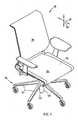
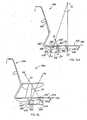
- a seating unit or chair 30( Fig. 1 ) includes a base 31, and includes a motion control mechanism (sometimes shortened and referred to as "motion control" herein) comprising a plurality of flexible supports 32 mounted to the base 31 for movably supporting a seat 34 and a back 35 on the base 31 for synchronous movement during recline.
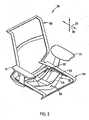
- the flexible supports 32are stiff in a generally vertical direction 37, but flexible in a generally fore-to-aft direction 36, and further, the flexible supports 32 have end sections 33 ( Fig. 2 ) projecting generally outward from the central support 44 positioned in a relatively central area of the motion control. The end sections 33 move relative to the central support 44 during operation.
- the illustrated support 44includes three mounting areas 45-47.
- a bottom of the central support 44, near middle mounting area 46 ( Fig. 8 )includes a tapered bottom recess for mateably engaging a top of the pneumatic spring 43.
- the mounting areas 45-47each include an angled surface or slot 45'- 47' for receiving the supports 32.
- the illustrated front two angled surfaces 45' and 46'( Fig. 5 ) face forwardly and are angled rearwardly with respect to vertical about 40° to 50°. More preferably, the front angled surface 45' extends at about 46° and the middle angled surface 46' extends at about 42°.
- the angle of the supports 32can be changed by using replaceable wedge-shaped spacers, such spacer 145 ( Figs. 5-7 ).
- spacer 145spacer 145
- the illustrated arms 51( Figs. 9-10 ) have a larger vertical dimension near the center section 49 and a smaller vertical dimension near their ends, but it is contemplated that the arms can have a variety of shapes.
- the illustrated flexible supports 32have a constant thickness, but it is also contemplated that the thickness may be varied along their length to provide a particular force versus deflection curve upon recline.
- the illustrated flexible supports 32are made of spring-steel, but they could be made of reinforced (or nonreinforced) polymeric materials, composite materials, and other materials as well. Accordingly, flexible supports 32 can be manufactured individually out of flat sheet stock (or molded or otherwise individually formed into more complex shapes) or can be molded into a single structure with central support 44.
- flexible supports 32are stiff, yet resilient and store energy upon flexure in the fore-aft direction in the preferred embodiment. Where pretension is applied to the support 32 to assist in holding the chair in a raised position, the support 32 preferably is made of a material that will not creep, such as spring-steel.
- the illustrated seat 34( Fig. 8 ) includes a seat carrier or frame 53 with side sections having front and rear cylindrical recesses 54 for receiving the bearings 52 of the front and middle flexible supports 32.
- the illustrated frame 53is U-shaped, and includes side sections 53' defining a perimeter of the seat area.
- a seat subassembly 55is attached atop the frame 53, and includes a generally planar, cushioned semi-resilient support 56 extended between the sides of its subframe. It is contemplated that this support can be replaced with a fabric or replaced with a more contoured cushion (whether thick or thin). Thicker or thinner cushions can also be placed on the frame 53. It is also contemplated that other traditional and non-traditional seats can be used on the present invention.
- the back frame 60includes lower legs 65 pivoted to a rear of the seat frame 53 at back pivot 66. Forward and rearward back stops (not shown) are used at back pivot 66 to control the amount of back recline, which preferably is approximately 22° of back recline motion in an office chair product. Other types of seating units may have different preferred ranges of back recline. It is contemplated that the flexible supports 32 can be given a pretension during assembly of the flexible supports 32 to the chair, so that the back 35 provides an initial level of support force to a seated user. This initial level must be overcome before the back 35 will permit recline.
- a center of the flexible support 32is fixed to the mating angled surface on one of the blocks of the central support 44 by screws 50.
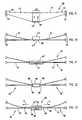
- the central supportis modified to be a box-shaped structure 44' or concave structure that permits a center section 77 of the flexible support 32 to resiliently bend and flex when the arms 51 flex. As can be seen, this causes an effective length of the arms 51 to be "longer", due to flexure of the center area 77 of the flexible support 32. It is noted that the arms 51 themselves may be strong enough to stay straight (see Fig. 11 ) or may themselves resiliently bend (see Fig. 10 ).
- Fig. 12illustrates a motion control mechanism utilizing modified flexible supports 32'.
- the arm sections 51are relatively stiff and not resilient, but the arms 51 are pivotally mounted to sides of the central support box 78 at pivot locations 80 such that they are flexible. Further, torsion springs 81 could be attached at pivot locations 80 to bias the arms 51 toward their upright positions. (The solid lines illustrate the upright positions, and the dashed lines represent the fully reclined positions.)
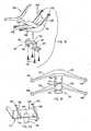
- Figs. 18-20illustrate a motion control mechanism where the front two flexible supports 32E are integrally molded of plastic as arms extending from sides of a hollow box-shaped housing 170, and where the central support 44E comprises a cast metal member 171 attached with screws 172 into a bottom recess of the hollow housing 170.
- the rear support 32Eis made of spring-steel and is attached by screws to a rear angled mounting surface 47E' formed by an end of the housing 170.
- the housing 170( Fig. 19 ) includes sidewalls 173, bosses 174 on the sidewalls for receiving the screws 172, transverse ribs 175 for reinforcement, and interlock tabs 176.
Landscapes
- Health & Medical Sciences (AREA)
- Dentistry (AREA)
- General Health & Medical Sciences (AREA)
- Chairs Characterized By Structure (AREA)
- Chairs For Special Purposes, Such As Reclining Chairs (AREA)
- Chair Legs, Seat Parts, And Backrests (AREA)
- Seats For Vehicles (AREA)
Description
- The present invention relates to seating units having motion controls, and more particularly relates to a seating unit having mechanically non-complex motion control elements, but which are efficient and effective.
- Modern chairs often have backs and seats that move upon recline of a person seated in the chairs.
US 4 575 150 A1 dicloses a suspension arrangement for a tilting chair. More sophisticated chairs include motion control mechanisms to provide sliding and pivoting motions that move in a particular way relative to the seated user so as to provide an optionally comfortable and adjustable chair motion. However, these mechanisms tend to be sophisticated with rigid pivot end slide elements which can result in complex control mechanisms that have many pieces and are difficult to assemble. In turn, the chair becomes expensive. Further, the mechanisms take up space and can become structurally large in size. which is unacceptable for chairs requiring a thin profile or otherwise requiring a clean unobstructed area under their seat. Also, design of these mechanisms is a complex task, with substantial time required to understand and work out competing functional requirements and physical relationships. - Accordingly, a seating unit with motion control mechanism is desired having the aforementioned advantages and solving the aforementioned problems, including having a relatively small, compact mechanism that is flexible and adaptable for different circumstances, and yet that provides a comfortable motion. Also, a motion control mechanism is desired that is easier to incorporate into chair designs without substantial design time, prototyping, and testing.
- According to the present invention there is provided a seating unit as claimed in claim 1.
- An object of the present invention is to provide a simple mechanism for movably supporting a seat and/or a back, and which is durable and low-cost, and which is easy to design and assemble.
- Another object is to provide a simple mechanism that can be adjusted to change the path of movement of a seat or back.
- These and other features, objects, and advantages of the present invention will become apparent to a person of ordinary skill upon reading the following description and claims together with reference to the accompanying drawings.
Fig. 1 is a front perspective view of a chair embodying the present invention;Fig. 2 is a front perspective view ofFig. 1 , the seat, back, and base/legs being removed to better show the underlying components;Figs. 3-5 are front, top, and side views ofFig. 1 ;Fig. 5A is a fragmentary side view of a modified version of the back pivot area, similar toFig. 5 , but with an integral back stop feature;Fig. 6 is a side view similar toFig. 5 , but showing the chair in a reclined position;Fig. 7 is a schematic side view of the motion control mechanism shown inFig. 5 ;Fig. 8 is an exploded side view ofFig. 5 Fig. 9 is a front view of the flexible supports of the underseat motion control mechanism shown inFig. 5 ;Fig. 10 is a top view ofFig. 9 , the solid lines showing an at-rest position and the dashed lines showing flexure of the flexible support ofFig. 9 ;Figs. 10A-10B are enlarged cross-sectional and end views of the outer end of the flexible support ofFig. 5 , showing coupling of the outer end to the stationary base frame;Figs. 10C-10D are enlarged cross-sectional and end views similar toFigs. 10A-10B , but showing an alternative embodiment;Fig. 11 is a top view of an alternative motion control mechanism, where the support block is a box-shaped shell and the illustrated flexible support has a resilient bendable center section;Fig. 12 is a top view of an alternative motion control mechanism, where the flexible support is rigid and pivoted to the support block at an inner end, the flexible support being spring-biased toward a home position;Fig. 13 is a top view of a motion control mechanism similar toFig. 10 , and including an adjustable device for changing an effective length of the flexible section of the flexible supports;Fig. 14 is a side view of a modified chair which is an illustrative example and is not part of the invention, the modified chair including a pair of flexible supports and a one-piece bucket forming a back and seat that, upon recline, rotate about an axis aligned near the center of gravity of the seated user;Fig. 14A is a side view of another modified chair similar toFig. 5 , but having a synchronized seat and back motion where the seat moves forward upon recline of the back;Fig. 15 is a perspective view of another modified chair which is an illustrative example and is not part of the invention, the chair including stationary upright side panels, two flexible supports with ends supported by the side panels, and a seat/back bucket mounted to a center of the flexible supports for reclining movement;Figs. 16-17 are top views of a modified motion control mechanism similar toFig. 2 , but where the flexible supports are molded along with the center support block and the seat frame as a one-piece integral molding,Fig. 16 showing the molding in an unstressed condition andFig. 17 showing the molding in a stressed condition with the seat frame section moved rearward relative to the center support, such as will occur during recline;Fig. 18 is an exploded perspective view of a modified motion control mechanism, where the flexible supports are integrally molded with a hollow central support, and where a cast metal member mounts to bottom of the central support for engaging a base pneumatic post; andFigs. 19 and 20 are top and side views of the molded member shown inFig. 18 .- A seating unit or chair 30 (
Fig. 1 ) includes abase 31, and includes a motion control mechanism (sometimes shortened and referred to as "motion control" herein) comprising a plurality offlexible supports 32 mounted to thebase 31 for movably supporting aseat 34 and aback 35 on thebase 31 for synchronous movement during recline. Theflexible supports 32 are stiff in a generallyvertical direction 37, but flexible in a generally fore-to-aft direction 36, and further, theflexible supports 32 have end sections 33 (Fig. 2 ) projecting generally outward from thecentral support 44 positioned in a relatively central area of the motion control. Theend sections 33 move relative to thecentral support 44 during operation. Theseat 34 and theback 35 are operably supported on and coupled to theend sections 33 of theflexible supports 32, so that when the flexible supports 32 flex in the generally fore-to-aft direction 36, they provide for synchronous movement of theseat 34 and/or theback 35, as described below. The illustratedflexible supports 32 comprise leaf-spring-like members forming a "flexible beam". The illustrated flexible supports have a vertical dimension for supporting considerable weight, yet have a relatively thin thickness dimension permitting their ends to flex and bend in a fore-aft direction and to absorb energy during their flexure. Further, theflexible supports 32 are slightly angled from a vertical orientation to provide a predetermined path of movement of theseat 34 andback 35, as discussed below. It is noted that the term "flexible" is used herein to mean that thesupports 32 can move, such as by pivoting (seeFig. 12 ) or by resiliently bending (seeFig. 10 ). - The base 31 (
Fig. 1 ) includes ahub 40 and radially-extendingcastored legs 41. Acenter tube 42 extends vertically from thehub 40, and a vertically-extendable pneumatic spring 43 (Fig. 8 ) is positioned in thetube 42 for providing a pneumatically-assisted chair height adjustment. The illustratedbase 31 includes a base plate orcentral support 44 with multiple mounting locations or mounting sections 45-47 thereon. Other types of bases, such as beams, posts, and attachment plates (whether movable or immovable) are contemplated. - The illustrated
support 44 includes three mounting areas 45-47. A bottom of thecentral support 44, near middle mounting area 46 (Fig. 8 ) includes a tapered bottom recess for mateably engaging a top of thepneumatic spring 43. The mounting areas 45-47 each include an angled surface or slot 45'- 47' for receiving thesupports 32. The illustrated front two angled surfaces 45' and 46' (Fig. 5 ) face forwardly and are angled rearwardly with respect to vertical about 40° to 50°. More preferably, the front angled surface 45' extends at about 46° and the middle angled surface 46' extends at about 42°. The angled surfaces 45' and 46' are nearly parallel, but the middle angled surface 46' has a slightly smaller angle, such that during recline, theend sections 33 of the middleflexible support 32 move upwardly at a slower rate than theend sections 33 of the frontflexible support 32. This causes theseat 34 to move translationally and angularly along a predeterminedpreferred path 48 upon recline, as discussed below. The angled surface 47' faces rearwardly and is tipped forwardly such that it is at a reverse angle to the front angled surfaces 45' and 46', with the surface 47' being at an angle of about 15 ° to 25° from vertical (with a 20° angle being preferred). It is noted that the angle of thesupports 32 can be changed by using replaceable wedge-shaped spacers, such spacer 145 (Figs. 5-7 ). However, it is desirable to keep the pivot locations (i.e. bearings 52) at the same locations so that the seat and back paths do not unacceptably change away from the intended design upon recline, and so that thesupports 32 do not move and flex in a dramatically different way. - The illustrated flexible supports 32 (
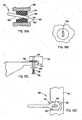
Fig. 9 ) (also called "flexible beams") are planar leaf-spring-like members. The term "flexible" is used herein to define any fore-aft movement, including bending or pivoting, while the term "resilient" is used herein to mean bending along with energy absorption during flexure. Eachsupport 32 includes anenlarged center section 49 attached to the angled surfaces 45'- 47' byfasteners 50, and further includes resilientlyflexible arms 51 that taper in height toward theend sections 33 and that are supported onbearings 52. The bearings 52 (Fig. 9 ) operably receive the outer ends of thearms 51, such that the outer ends can both slip linearly and also rotate as thearms 51 flex and move. It is contemplated that various connecting arrangements can be made for connecting the ends of thearms 51 to the frames of theseat 34 or back 35. For example, a bearing arrangement 100 (Figs. 10A ) includes a polymeric stationary support bearing 101 positioned in abore 102 in the illustratedseat frame section 103. Thebearing 101 includes a vertically elongated slit 104 with tapered front andrear ends end 107 of thearm 51. The ends 105 and 106 form an "hour-glass" shaped slot arrangement that allows theend 107 of thearm 51 to rock back and forth and telescopingly slip as thesupport 32 is flexed. This helps distribute stress on theend 106 as thearm 51 of theflexible supports 32 are flexed, and eliminates "point" stress that may be damaging to or wearing on thearm 51. Also, the mating/abutting shape of the front andrear ends end 107 of thearms 51 to act as a stop that limits the reclining motion. - It is contemplated that other steps to limit the reclining motion can be added. The modified arrangement shown in
Fig. 5A includes anarcuate slot 53A' in theseat frame 53A that extends partially around the back pivot 66A. A pin 55D' in an end ofleg 65D slides along theslot 53A' and engages ends of theslot 53A' to stop the back 35 in the upright and reclined positions. There are other ways that a back stop mechanism can be provided. For example, a fixed radially extending protrusion can be connected to the pivot pin atback pivot 66, with the protrusion engaging a bottom of the seat frame upon reaching a maximum recline position. This back stop mechanism could be modified to become adjustable, by using a rotatable stepped wheel on the pin atback pivot 66 instead of a fixed protrusion on the pin, with steps on the wheel selectively engaging a lip on the seat frame to set different maximum recline positions. - A modified bearing arrangement 110 (
Figs. 10C-10D ) includes a modifiedend 111 to theflexible support 32. The modifiedend 111 includes a flattenedsection 112 with alongitudinal slot 113 therein (Fig. 10D ). A threaded fastener 114 (Fig. 10C ) is extended through abushing 115 up through theslot 113 and awasher 116 threadably into ahole 117 in theside section 118 of a seat frame. The threadedfastener 114 includes ashaft 119 that slides back and forth in theslot 113 as the flexible support is flexed during recline. Theshaft 119 engages the ends of theslot 113 to limit the seat (or back) in the upright and recline positions. - It is also contemplated that the
bearings 52 can be cylindrically or spherically shaped and attached to ends of thesupports 32, and operably positioned in a bore in the seat frame for simultaneous rotation and telescoping movement. - The illustrated arms 51 (
Figs. 9-10 ) have a larger vertical dimension near thecenter section 49 and a smaller vertical dimension near their ends, but it is contemplated that the arms can have a variety of shapes. The illustratedflexible supports 32 have a constant thickness, but it is also contemplated that the thickness may be varied along their length to provide a particular force versus deflection curve upon recline. The illustratedflexible supports 32 are made of spring-steel, but they could be made of reinforced (or nonreinforced) polymeric materials, composite materials, and other materials as well. Accordingly,flexible supports 32 can be manufactured individually out of flat sheet stock (or molded or otherwise individually formed into more complex shapes) or can be molded into a single structure withcentral support 44. It should also be noted thatflexible supports 32 are stiff, yet resilient and store energy upon flexure in the fore-aft direction in the preferred embodiment. Where pretension is applied to thesupport 32 to assist in holding the chair in a raised position, thesupport 32 preferably is made of a material that will not creep, such as spring-steel. - Because of the angle of surfaces 45'- 47' and because of the interaction of
back frame 60 andseat frame 53 withsupports 32, theseat 34 is actually lifted during recline. (CompareFig. 5 which is the upright position, withFig. 6 , which shows the recline position.) This seat-lifting action helps provide the additional energy necessary when the heavier person reclines. In other words, the energy stored during recline (i.e. due to the seat being lifted) provides some of the energy to assist the seated person when moving from the reclined position toward the upright position. Because theback frame 60 experiences the greatest change in load, it is contemplated that the rearmostflexible support 32 resists flexure the strongest (or, said another way, stores the most energy on recline) while the forwardmostflexible support 32 need not necessarily be as strongly resistant to flexure in the fore-to-aft direction. - The illustrated seat 34 (
Fig. 8 ) includes a seat carrier orframe 53 with side sections having front and rearcylindrical recesses 54 for receiving thebearings 52 of the front and middle flexible supports 32. The illustratedframe 53 is U-shaped, and includes side sections 53' defining a perimeter of the seat area. Aseat subassembly 55 is attached atop theframe 53, and includes a generally planar, cushionedsemi-resilient support 56 extended between the sides of its subframe. It is contemplated that this support can be replaced with a fabric or replaced with a more contoured cushion (whether thick or thin). Thicker or thinner cushions can also be placed on theframe 53. It is also contemplated that other traditional and non-traditional seats can be used on the present invention. - The back 35 (
Fig. 8 ) includes a back carrier orframe 60 with side sections having front and rearcylindrical recesses 61 for receiving thebearings 52 of the rearflexible support 32. The illustratedframe 60 has an inverted U-shape that defines a perimeter of the back. A generally resilient cushionedsupport panel 64 is extended between the sides of theframe 60. It is contemplated that the cushionedpanel support 64 can be replaced with a fabric or replaced with a cushioned or contoured panel. A cushion can also be placed on theframe 60. It is also contemplated that other traditional and non-traditional backs can be used on the present invention. - The
back frame 60 includeslower legs 65 pivoted to a rear of theseat frame 53 atback pivot 66. Forward and rearward back stops (not shown) are used atback pivot 66 to control the amount of back recline, which preferably is approximately 22° of back recline motion in an office chair product. Other types of seating units may have different preferred ranges of back recline. It is contemplated that theflexible supports 32 can be given a pretension during assembly of theflexible supports 32 to the chair, so that the back 35 provides an initial level of support force to a seated user. This initial level must be overcome before the back 35 will permit recline. This pretension can result solely from the strength of theflexible supports 32, and/or can be from separate springs used to supplement the strength offlexible supports 32 to provide an initial level of support before the back will recline. For example, torsion springs can be operably attached at thepivot 66 to provide a bias on the back 35 to an upright position. Also, a coil spring could be operably connected between the seat andcenter support 44. Also, a variety of different arrangements are possible for controlling the location of the upright and recline positions, as will be apparent to artisans skilled in this art. In the illustrated arrangement, therearmost support 32 is made of steel, and carries a bulk of any pretension, while the front twosupports 32 carry less pretension and hence can be made of polymeric materials (which would creep over time if pretensioned). - Armrest assemblies 71 (
Fig. 8 ) include anupright support 72 attached to the side sections of theseat frame 53, and further include anarmrest body 73 comprising an L-shapedstructural support 74 and acushion 75. It is contemplated that a variety of different armrests can be used on the present invention. - In
Figs. 9-10 , a center of theflexible support 32 is fixed to the mating angled surface on one of the blocks of thecentral support 44 byscrews 50. InFig. 11 , the central support is modified to be a box-shaped structure 44' or concave structure that permits acenter section 77 of theflexible support 32 to resiliently bend and flex when thearms 51 flex. As can be seen, this causes an effective length of thearms 51 to be "longer", due to flexure of thecenter area 77 of theflexible support 32. It is noted that thearms 51 themselves may be strong enough to stay straight (seeFig. 11 ) or may themselves resiliently bend (seeFig. 10 ). Where resilient leaf-spring-like supports 32 are used, the vertical dimension is large enough relative to its width dimension (i.e. its thickness), so that the vertical beam stiffness is at least about 50 times its lateral bending stiffness. The reason for this 50:1 ratio is so that thesupports 32 can carry considerable weight, while allowing fore-aft movement with less force. As this ratio declines, there is less control of the seat and back movement, and a stiffer fore-aft movement, which results in a less controlled feel to a seated user. Fig. 12 illustrates a motion control mechanism utilizing modified flexible supports 32'. Thearm sections 51 are relatively stiff and not resilient, but thearms 51 are pivotally mounted to sides of thecentral support box 78 atpivot locations 80 such that they are flexible. Further, torsion springs 81 could be attached atpivot locations 80 to bias thearms 51 toward their upright positions. (The solid lines illustrate the upright positions, and the dashed lines represent the fully reclined positions.)Fig. 13 illustrates an adjustableback stiffness mechanism 85 attached to the motion control ofFig. 11 instead of to thepivots 66. In theback stiffness mechanism 85, arotatable gear 86 is attached within thebox 78 and is connected to a lever or handle in a convenient location for manipulation by a seated user. A pair ofslides box 78, with theirouter end sections 90 extending outward in sliding engagement with thearms 51. Theslides gear 86. As thegear 86 is rotated, theouter end sections 90 are driven outward in direction X. This results in a shorter effective length of thearms 51. This, in turn, dramatically increases the stiffness during recline, since the shortened length ofarms 51 must be bent to a much greater extent to reach a fully reclined position. This increased stiffness would support a heavier user during recline.- In the description of chairs and motion control components below, components that are similar to or identical to the components of
chair 30 are described using the same identification numbers, but with the addition of the letters "A", "B", "C", "D", and "E", respectively. This is done to reduce redundant discussion. - A modified
chair 30A (Fig. 14 ) is shown that is not unlike thechair 30. However, thechair 30A includes a one-piece unitary seat and back 34A (i.e. a "bucket" type chair), and further includes only twoflexible supports 32A. Specifically, thebase tube 43A supports abase plate 44A having two mountingblocks middle mount block 46A includes a tapered bottom recess for mateably engaging a top of itspneumatic spring 43A. The frontangled surface 45A' is angled rearwardly about 35° to 55°, or more preferably about 45°. The rearwardangled surface 46A' is angled forwardly a small amount, such as about 5° to 15°, or more preferably about 10°. During recline, this causes a rear of theseat section 34A to drop and the front of theseat section 34A to rise whileseat section 34A moves forward about a virtual pivot located about at a seated user's center of gravity. Also, a top edge of the back section 35A pivots downwardly as well as rearwardly during recline. (See arrows inFig. 14 .) The net result is that the seat and back pivot about a pivot axis A1 that is located above the seat, such as at a location about equal to a seated user's center of gravity. Notably, the axis of rotation is easily and predictably changeable. For example, axis A1 is located at the intersection of lines extending from thesurfaces 45A' and 46A'. Ifrear surface 46A' is changed to be oriented vertically, the axis of rotation upon recline becomes A2. Ifsurface 46A' is changed to be oriented at about 5° rearwardly, the axis of rotation upon recline becomes axis A3. Similarly, if the angle ofrear surface 46A' isnot changed, but instead, the angular orientation ofsurface 45A' is changed to vertical, the axis of rotation upon recline becomes A4. It is specifically contemplated that the axis of rotation of either the back or seat can be controlled by this method. (CompareFig. 14 to Figs. 5 and6 .) The chair 30D (Fig. 14A ) illustrates this concept. The chair 30D has a seat forward motion upon back recline that is similar to the motion of the synchrotilt chair disclosed inU.S. Patent No. 5,975,634 (issued November 2, 1999 , entitled "Chair Including Novel Back Construction", to Knoblock et al.), where a front of the seat moves forward and up during recline and where a rear of the seat moves forward and down during recline. To obtain this result, the frontflexible support 32 is mounted at an angle of about 4°, while the middleflexible support 32 is mounted at an angle of about +20°, and the rearflexible support 32 is mounted at an angle of about -20°. Also, theback frame leg 65D is pivoted to an end of themiddle support 32D atpivot 66D, while theseat frame 53D is pivoted to theback frame leg 65D atpivot 53D'. When flexed, thepivot 66D moves forward and up, while therear pivot 66D' moves forward and down. As a result, theback 60D rotates about axis D1 while theseat 34D rotates forward about axis D2 upon recline. - It is contemplated that a chair can also be constructed to include only a single flexible support at a rear of the seat. In such case, the front of the seat is supported by a sliding bearing arrangement, such as a linear bearing on the seat that slides on a track on the base plate. It is noted that the track can be made linear, curvilinear, or arcuate, as desired. Also, biasing springs can be operably attached to the bearing and/or the seat to assist in biasing the seat (and back) to an upright position.
- Notably, the
flexible supports 32 can be "reversed", with their ends being supported by a stationary member, and theircentral support 44 being movable upon recline.Chair 30B (Fig. 15 ) illustrates one such arrangement. It is contemplated that thischair 30B would potentially be useful in a stadium or auditorium or mass transit seating arrangement.Chair 30B includes a pair of spaced-apartstationary side panels 150 secured stably together, such as by connectingrods 151. The flexible supports 32B are positioned with the outer ends of their arms 51B slidably/telescopingly engaging apertures 152 in thepanels 150. Acentral support 44B is attached to a center section of theflexible supports 32B. Aseat 34B and back 35B are fixedly attached to thecentral support 44B. Notably, the back 35B can include a back frame or support panel having some flexibility and compliance for increased comfort. Also, theseat 34B can have a similar flexibility. Side edges of theseat 34B move along a path between and proximate theside panels 150. This helps keep the seat "square" and stable during recline. - In another variation, a unitary control construction 160 (
Figs. 16-17 ) is provided where theflexible supports 32C are integrally molded to both theseat frame 161 and thecentral support 44C. As illustrated, theflexible supports 32C havearms 51C with an S-shaped configuration when viewed from above. As thecentral support 44C is moved rearwardly upon recline, thearms 51C flex and resiliently bend, temporarily pressing theside sections 162 of theseat frame 161 outwardly slightly. Thus, both the flexing of theflexible supports 32C and also the flexing of theside sections 162 provide stored energy for assisting a seated user to move from a recline position to the upright position. Further, since the illustrated assembly is a one-piece molding, manufacturing costs are lowered and assembly costs are virtually eliminated in regard to the illustrated components. Notably, thecentral support 44C includes an angledrear mounting surface 47C' where a steel leaf-spring-like member can be mounted, so as to provide a steel support that can be pretensioned without fear of creeping. Figs. 18-20 illustrate a motion control mechanism where the front twoflexible supports 32E are integrally molded of plastic as arms extending from sides of a hollow box-shapedhousing 170, and where thecentral support 44E comprises acast metal member 171 attached withscrews 172 into a bottom recess of thehollow housing 170. Therear support 32E is made of spring-steel and is attached by screws to a rear angled mountingsurface 47E' formed by an end of thehousing 170. The housing 170 (Fig. 19 ) includessidewalls 173,bosses 174 on the sidewalls for receiving thescrews 172,transverse ribs 175 for reinforcement, and interlocktabs 176. Thecast metal member 171 includes aplate 177 shaped to engage thesidewalls 173 and cover the bottom of thehousing 170. An inverted cup-shapedstructure 178 forms a tapered socket for receiving a toptapered section 179 of the pneumatic height-adjustable post 180 onbase 31E.Ribs end plate 183 stabilize thestructure 178 on thebase plate 177, and further interfit between thebosses 174 and interlocktabs 176 to form a secure nested assembly of thecast metal member 171 to thehousing 170. Notably, thearms 51E are angled and the end sections are raised above thehousing 170, such that even though the illustratedarms 51E are generally planar, they have the appearance shown inFigs. 19-20 when viewed from above and from a side view.
Claims (21)
- A seating unit having a base (31), comprising:a motion control adapted for mounting to the base (31) and having a central area and a plurality of flexible support (32), said flexible supports being flexible in a generally fore-to-aft direction but stiff in a generally vertical direction, the flexible supports (32) further having end sections (33) projecting generally outward from said central area;a seat (34) supported on said end sections (33) at least one of said flexible supports (32);a back (35) pivotally connected to said seat (34) at a first pivot connection (66) and pivotally connected to said end sections (33) of at least one other of said flexible supports (32), andwherein said flexible supports (32) flex in said generally fore-to-aft direction to provide synchronous movement of said back (35) and seat (34).
- The seat unit as set forth in Claim 1 wherein said flexible supports (32) have a resilient section and a rigid section.
- The seating unit as set forth in Claim 1 wherein at least one of said flexible supports (32) is resilient.
- The seating unit as set forth in Claim 1 therein said flexible supports (32) are mounted in spaced relation to each other and generally transverse to said seat (34), at least one of said flexible supports (32) being positioned at a selected angle relative to vertical, said flexible supports (32) being sufficiently rigid to support said seat (34) while being sufficiently flexible in at least one direction to allow for controlled mouvement of said seat (34) and back (35).
- The seating unit as set forth in Claim 1, wherein the seat (34) is pivoted to at least one of the flexible supports by a pivot bushing.
- The seating unit as set forth in Claim 1, wherein the seat (34) is slidably connected to one of the base (31) and flexible supports (32) by a sliding member.
- The seating unit as set forth in Claim 1, therein at least one of the flexible supports (32) comprises an energy component having a first stiffness property in a vertical direction and a second stiffness property in a fore-aft horizontal direction, a ratio of the first stiffness property to the second stiffness property being at least 50:1.
- The seating unit as set forth in Claim 1 wherein at least one of said flexible supports (32) is a leaf spring.
- The seating unit as set forth in Claim 1 wherein at least one of said flexible supports (32) is positioned at a selected angle relative to vertical.
- The seating unit as set forth in Claim 9 wherein one of said flexible supports (32) is positioned at an acute angle to another of said flexible supports.
- The seating unit as set forth in Claim 1 wherein each of said flexible supports (32) have a front surface facing in a generally forwardly angled direction.
- The seating unit as set forth in Claim 1 wherein said flexible supports (32) have end section (33) and a center section (49).
- The seating unit as set forth in Claim 12 wherein said end sections (33) are flexible and movable, and said center section (49) is rigid.
- The seating unit as set forth in Claim 1 wherein an energy component separate from said flexible supports (32) provides at least a section of the force to support the synchronous movement of said back (35) and seat (34).
- The seating unit as set forth in Claim 1, wherein said synchronous movement includes said seat (34) moving forward as said back (35) is reclined.
- The seating unit as set forth in Claim 1 wherein said synchronous movement includes said seat (34) moving forwardly and upwardly upon recline of said back (35).
- The seating unit as set forth in Claim 1 wherein said flexible supports (32) are separate elements.
- The seating unit as set forth in Claim 1 wherein at least one of said flexible supports (32) is resilient and comprises an energy component.
- The seating unit as set forth in Claim 1 wherein said flexible supports (32) and central area are integrally molded as a one-piece structure.
- The seating unit as set forth in Claim 1 wherein said flexible supports (32) have a cross section in the fore-to-aft direction that is smaller than a vertical height of said flexible supports (32).
- The seating unit as set forth in Claim 1 wherein said seating unit is an office chair
Applications Claiming Priority (3)
| Application Number | Priority Date | Filing Date | Title |
|---|---|---|---|
| US10/241,955US6869142B2 (en) | 2002-09-12 | 2002-09-12 | Seating unit having motion control |
| US241955 | 2002-09-12 | ||
| PCT/US2003/027923WO2004023935A2 (en) | 2002-09-12 | 2003-09-08 | Seating unit having motion control |
Publications (3)
| Publication Number | Publication Date |
|---|---|
| EP1551255A2 EP1551255A2 (en) | 2005-07-13 |
| EP1551255A4 EP1551255A4 (en) | 2006-06-14 |
| EP1551255B1true EP1551255B1 (en) | 2013-11-06 |
Family
ID=31991293
Family Applications (1)
| Application Number | Title | Priority Date | Filing Date |
|---|---|---|---|
| EP03752052.5AExpired - LifetimeEP1551255B1 (en) | 2002-09-12 | 2003-09-08 | Seating unit having motion control |
Country Status (12)
| Country | Link |
|---|---|
| US (3) | US6869142B2 (en) |
| EP (1) | EP1551255B1 (en) |
| JP (1) | JP4584712B2 (en) |
| KR (1) | KR20050036999A (en) |
| CN (2) | CN1787766B (en) |
| AU (1) | AU2003270364B2 (en) |
| BR (1) | BR0314232B1 (en) |
| CA (1) | CA2498704C (en) |
| HK (1) | HK1079974A1 (en) |
| MX (2) | MXPA05002604A (en) |
| TW (1) | TWI272080B (en) |
| WO (1) | WO2004023935A2 (en) |
Cited By (1)
| Publication number | Priority date | Publication date | Assignee | Title |
|---|---|---|---|---|
| EP4616763A1 (en) | 2024-03-15 | 2025-09-17 | Cerantola S.P.A. | Chair for user sitting |
Families Citing this family (83)
| Publication number | Priority date | Publication date | Assignee | Title |
|---|---|---|---|---|
| US6880886B2 (en) | 2002-09-12 | 2005-04-19 | Steelcase Development Corporation | Combined tension and back stop function for seating unit |
| US7048335B2 (en)* | 2003-06-05 | 2006-05-23 | Steelcase Development Corporation | Seating unit with crossbar seat support |
| USD509969S1 (en)* | 2003-09-05 | 2005-09-27 | Steelcase Development Corporation | Seating unit |
| NZ529154A (en)* | 2003-10-24 | 2006-07-28 | Furnware Ltd | Recline mechanism for seating furniture |
| USD536890S1 (en)* | 2004-03-03 | 2007-02-20 | Steelcase Development Corporation | Seating unit |
| USD552368S1 (en)* | 2004-06-07 | 2007-10-09 | Steelcase Development Corporation | Chair |
| US6979059B1 (en)* | 2004-09-16 | 2005-12-27 | Hc Holdings, Llc | Rocking chair construction |
| US7669922B2 (en)* | 2004-11-05 | 2010-03-02 | Ultra-Mek, Inc. | Reclining seating unit with backrest support frame |
| US20060238004A1 (en)* | 2005-04-12 | 2006-10-26 | Conner John P | Modular seating system |
| US7222868B2 (en)* | 2005-06-01 | 2007-05-29 | Steelcase Development Corporation | Seating unit with wheelchair base |
| CA2665176C (en) | 2006-10-04 | 2016-01-19 | Formway Furniture Limited | A back portion for a chair with a moveable upper section |
| US7695067B2 (en)* | 2007-03-02 | 2010-04-13 | Goetz Mark W | Ergonomic adjustable chair |
| ITMI20070718A1 (en)* | 2007-04-06 | 2008-10-07 | L & P Property Management Co | ADJUSTMENT DEVICE FOR ADJUSTABLE AND SIMILAR CHAIRS. |
| USD604535S1 (en) | 2008-04-09 | 2009-11-24 | Formway Furniture Limited | Chair |
| USD600051S1 (en) | 2008-04-09 | 2009-09-15 | Formway Furniture Limited | Chair back |
| AU2009258164A1 (en)* | 2008-05-26 | 2009-12-17 | Steelcase Inc. | Conforming back for a seating unit |
| US8172324B2 (en)* | 2008-06-06 | 2012-05-08 | Knoll, Inc. | Preference control mechanism |
| US8216416B2 (en) | 2008-06-06 | 2012-07-10 | Knoll, Inc. | Chair and method for assembling the chair |
| US8167373B2 (en)* | 2008-06-06 | 2012-05-01 | Knoll, Inc. | Height adjustment mechanism for a chair |
| TWD133366S1 (en)* | 2008-10-24 | 2010-02-21 | 岡村製作所股份有限公司 | Chair |
| TWD133365S1 (en)* | 2008-10-24 | 2010-02-21 | 岡村製作所股份有限公司 | Chair |
| USD615783S1 (en)* | 2008-10-24 | 2010-05-18 | Okamura Corporation | Chair |
| CN102202546A (en)* | 2008-10-29 | 2011-09-28 | 株式会社冈村制作所 | Chair backrest |
| CA131020S (en) | 2008-12-12 | 2010-02-03 | Formway Furniture Ltd | Chair |
| NZ613957A (en) | 2008-12-12 | 2015-03-27 | Formway Furniture Ltd | A chair, a support, and components |
| USD601827S1 (en) | 2008-12-18 | 2009-10-13 | Formway Furniture Limited | Furniture base |
| US8002351B2 (en)* | 2009-01-26 | 2011-08-23 | Knoll, Inc. | Support member |
| US8157329B2 (en)* | 2009-02-25 | 2012-04-17 | Knoll, Inc. | Furniture and method of furniture component attachment |
| TWD135261S1 (en)* | 2009-03-31 | 2010-06-11 | 岡村製作所股份有限公司 | Chair |
| USD616654S1 (en)* | 2009-03-31 | 2010-06-01 | Okamura Corporation | Chair |
| US8944507B2 (en)* | 2009-10-13 | 2015-02-03 | Herman Miller, Inc. | Ergonomic adjustable chair mechanisms |
| NO331212B1 (en)* | 2009-10-19 | 2011-11-07 | Ekornes Asa | Fast Sofa |
| US8696056B2 (en)* | 2010-02-01 | 2014-04-15 | Steelcase Inc. | Seating unit |
| US20110277943A1 (en) | 2010-05-14 | 2011-11-17 | Whole Space Industries Ltd | Window Covering |
| US8616640B2 (en) | 2010-05-20 | 2013-12-31 | Knoll, Inc. | Chair |
| US20130169017A1 (en)* | 2010-06-11 | 2013-07-04 | Okamura Corporation | Chair |
| US8439441B2 (en) | 2010-09-29 | 2013-05-14 | Lear Corporation | Adjustable lumbar assembly for vehicle seats |
| US10543764B2 (en)* | 2010-10-01 | 2020-01-28 | Nissan Motor Co., Ltd. | Vehicle seat and stiffness setting method for vehicle seat |
| DE102011001811A1 (en)* | 2011-04-05 | 2012-10-11 | Wilkhahn Wilkening + Hahne Gmbh + Co. Kg | chair |
| US8567864B2 (en) | 2011-08-12 | 2013-10-29 | Hni Corporation | Flexible back support member with integrated recline stop notches |
| DE112012004365T5 (en)* | 2011-10-21 | 2014-07-03 | Jae Hyun Lee | Corrective chair with lubricant |
| US9107504B2 (en) | 2012-05-14 | 2015-08-18 | Peter J. Haas | Reclining loop frame stacking / swivel chair |
| USD707995S1 (en) | 2012-05-23 | 2014-07-01 | Hni Technologies Inc. | Chair |
| US9198514B2 (en) | 2012-05-23 | 2015-12-01 | Hni Technologies Inc. | Chair with pivot function and method of making |
| US9161630B2 (en)* | 2012-05-25 | 2015-10-20 | Faurecia Automotive Seating, Llc | Deformable seat shell with motion control |
| USD707477S1 (en) | 2012-08-29 | 2014-06-24 | Hni Technologies, Inc. | Chair |
| US8820835B2 (en) | 2012-08-29 | 2014-09-02 | Hni Technologies Inc. | Resilient chair incorporating multiple flex zones |
| USD707976S1 (en)* | 2013-06-07 | 2014-07-01 | Steelcase Inc. | Chair |
| USD706547S1 (en)* | 2013-06-07 | 2014-06-10 | Steelcase Inc. | Chair |
| USD703987S1 (en)* | 2013-06-07 | 2014-05-06 | Steelcase Inc. | Chair |
| USD743712S1 (en) | 2013-03-15 | 2015-11-24 | Herman Miller, Inc. | Chair |
| USD704487S1 (en)* | 2013-06-07 | 2014-05-13 | Steelcase Inc. | Chair |
| US10159350B2 (en)* | 2013-06-07 | 2018-12-25 | Okamura Corporation | Chair |
| USD711127S1 (en)* | 2013-09-20 | 2014-08-19 | Formway Furniture Limited | Chair |
| DE102013017312A1 (en)* | 2013-10-18 | 2015-04-23 | Km-System | Chair for long-term sitting |
| US9380879B2 (en) | 2014-02-24 | 2016-07-05 | Knoll, Inc. | Chair back swivel mechanism |
| JP6549371B2 (en) | 2014-04-03 | 2019-07-24 | 愛知株式会社 | chair |
| GB201412733D0 (en)* | 2014-07-17 | 2014-09-03 | Boss Design Ltd | Chair |
| US10194750B2 (en) | 2015-04-13 | 2019-02-05 | Steelcase Inc. | Seating arrangement |
| US10966527B2 (en) | 2017-06-09 | 2021-04-06 | Steelcase Inc. | Seating arrangement and method of construction |
| EP3282899B1 (en) | 2015-04-13 | 2021-11-03 | Steelcase Inc. | Seating arrangement |
| US11259637B2 (en)* | 2015-04-13 | 2022-03-01 | Steelcase Inc. | Seating arrangement |
| US9585485B2 (en) | 2015-05-15 | 2017-03-07 | Knoll, Inc. | Seating device having a tilt mechanism |
| US9883748B2 (en) | 2015-05-15 | 2018-02-06 | Knoll, Inc. | Training device for a seating device and method of using the same |
| US10143308B2 (en) | 2015-07-23 | 2018-12-04 | Herman Miller, Inc. | Seating device |
| EP3708032A1 (en)* | 2016-02-23 | 2020-09-16 | Kokuyo Co., Ltd. | Chair and seat support mechanism |
| US10463153B2 (en)* | 2016-06-09 | 2019-11-05 | Steelcase Inc. | Seating arrangement |
| CA3072085A1 (en) | 2017-08-10 | 2019-02-14 | Hni Corporation | Chairs including flexible frames |
| US10820703B2 (en)* | 2018-09-17 | 2020-11-03 | Sedus Stoll Ag | Chair, particularly conference or office chair, and method for manufacturing a chair |
| CH715343A1 (en) | 2018-09-18 | 2020-03-31 | Krob Andreas | Swivel chair. |
| DE102018219885B4 (en)* | 2018-11-20 | 2022-02-03 | Comfordy Co., Ltd. | Synchronous mechanism for a piece of seating furniture and seating furniture |
| CN113507865A (en) | 2019-02-21 | 2021-10-15 | 斯特尔凯斯公司 | Body support assembly and methods for use and assembly thereof |
| CN114007465A (en) | 2019-04-16 | 2022-02-01 | 赫尔曼米勒有限公司 | Active engagement chair for user |
| DE102019113240A1 (en)* | 2019-05-20 | 2020-11-26 | Bock 1 Gmbh & Co. Kg | Support component for a seat device |
| CN110432815B (en)* | 2019-08-13 | 2021-11-26 | 广东工业大学 | Auxiliary sitting up device for toilet |
| US11357329B2 (en) | 2019-12-13 | 2022-06-14 | Steelcase Inc. | Body support assembly and methods for the use and assembly thereof |
| US11617444B2 (en) | 2020-03-02 | 2023-04-04 | Steelcase Inc. | Body support assembly and methods for the use and assembly thereof |
| WO2022072543A1 (en)* | 2020-09-29 | 2022-04-07 | Rocking Inc. | Portable rebounding device with force adjustment assembly |
| US11812870B2 (en) | 2021-02-10 | 2023-11-14 | Steelcase Inc. | Body support structure |
| WO2022178129A1 (en)* | 2021-02-17 | 2022-08-25 | Hni Technologies Inc. | Chair with dynamic motion features |
| DE102021131277A1 (en)* | 2021-11-29 | 2023-06-01 | Bock 1 Gmbh & Co. Kg | Seat support kit for a chair |
| USD1063474S1 (en) | 2022-09-07 | 2025-02-25 | Steelcase Inc. | Chair |
| USD1079309S1 (en)* | 2025-01-23 | 2025-06-17 | Maozhong Yang | Dining chair |
Family Cites Families (80)
| Publication number | Priority date | Publication date | Assignee | Title |
|---|---|---|---|---|
| US312775A (en) | 1885-02-24 | Spring-seat | ||
| USRE24964E (en) | 1961-04-11 | Furniture frame construction | ||
| US144349A (en) | 1873-11-04 | Improvement in chairs | ||
| US389292A (en) | 1888-09-11 | flohr | ||
| US1513726A (en) | 1923-11-13 | 1924-10-28 | Lamplugh Henry Arthur | Seat |
| US2316628A (en) | 1942-05-16 | 1943-04-13 | Kroehler Mfg Co | Laminated flexwood spring for chair seats |
| US2731076A (en) | 1952-02-25 | 1956-01-17 | David L Rowland | Furniture seating |
| US2711211A (en)* | 1952-04-16 | 1955-06-21 | Tan Sad Chair Co 1931 Ltd | Resiliently mounted back rest |
| US2803293A (en) | 1953-10-12 | 1957-08-20 | David L Rowland | Spring assembly |
| US2818911A (en) | 1954-11-05 | 1958-01-07 | Trumbull Dev Corp | Tiltable office chair |
| US3271076A (en) | 1965-03-26 | 1966-09-06 | Heywood Wakefield Co | Seating construction |
| US3332719A (en) | 1965-04-26 | 1967-07-25 | Hyland C Flint | Spring seat |
| JPS4741208Y1 (en)* | 1969-10-14 | 1972-12-13 | ||
| US3720668A (en)* | 1970-08-12 | 1973-03-13 | Squibb & Sons Inc | Nitrofuryl-oxadiazole amides |
| US3720568A (en) | 1971-03-22 | 1973-03-13 | D Rowland | Seating and sub-assembly for seats and backs |
| US3934932A (en) | 1971-10-28 | 1976-01-27 | J.E. Ekornes Fabrikker A/S | Adjustable chair |
| US3888473A (en) | 1973-01-26 | 1975-06-10 | Hoover Ball & Bearing Co | Seat spring assembly |
| US4062590A (en) | 1976-05-24 | 1977-12-13 | Fixtures Manufacturing Corporation | Chair structure |
| US4247089A (en) | 1978-10-06 | 1981-01-27 | Morley Furniture Spring Construction | Spring construction |
| US4318556A (en) | 1979-06-11 | 1982-03-09 | Rowland David L | Chair and seat-back unit therefor |
| JPS6041157Y2 (en)* | 1979-11-06 | 1985-12-13 | 日本発条株式会社 | swing chair air |
| US4361357A (en)* | 1980-04-21 | 1982-11-30 | Pollock Charles R | Chair |
| AU544651B2 (en)* | 1980-11-17 | 1985-06-06 | Tor Arild | Universal mechanical linkage |
| US4586700A (en) | 1981-01-26 | 1986-05-06 | Morley Furniture Spring Corporation | Modular seat spring assembly |
| US4478454A (en) | 1981-06-08 | 1984-10-23 | Steelcase Inc. | Weight-actuated chair control |
| US4415147A (en) | 1981-10-09 | 1983-11-15 | Simmons Universal Corporation | Seating spring assembly and method |
| US4815717A (en) | 1982-12-30 | 1989-03-28 | Morley Furniture Spring Corporation | Spring assembly for upholstered furniture |
| US4653603A (en) | 1983-08-25 | 1987-03-31 | Gordon Rosenmeier | Rotary fluid devices |
| US4545614A (en) | 1984-02-09 | 1985-10-08 | General Motors Corporation | Thin elastomeric seat |
| CA1184108A (en)* | 1984-04-09 | 1985-03-19 | David W. Smith | Suspension arrangement for a tilting chair |
| DE3537203A1 (en)* | 1984-10-24 | 1986-04-24 | Klöber GmbH & Co, 7770 Überlingen | Work chair with inclination mechanism for seat and back |
| US4858992A (en) | 1985-10-07 | 1989-08-22 | Lasota Larry | Conformable seat |
| AT385406B (en) | 1986-02-28 | 1988-03-25 | Riedl Georg | Slatted base |
| US4715587A (en) | 1986-04-07 | 1987-12-29 | Morley Furniture Spring Corporation | Sinuous band and seat spring assembly |
| NO160896C (en) | 1986-05-09 | 1989-06-14 | Jurek Buchacz | ADJUSTABLE SEATING DEVICE. |
| US4818021A (en) | 1987-01-16 | 1989-04-04 | Martin Roysher | User variable chair |
| NO168985C (en) | 1987-10-19 | 1992-04-29 | Ekornes Fabrikker As J E | DEVICE AT CHAIR. |
| WO1989003649A1 (en)* | 1987-10-24 | 1989-05-05 | Kokuyo Co., Ltd. | Reclining chair |
| US4935977A (en) | 1988-01-27 | 1990-06-26 | Yamada Co., Ltd. | Leaf spring |
| IT1219016B (en) | 1988-02-12 | 1990-04-24 | Tis Tecnologia Innovazione Sti | SPRING AND LATERAL CONTAINMENT ELEMENT FOR A SEAT AND OR BACK OF A SEAT AND SEAT IN CORPORATE SUCH ELEMENT |
| US4911501A (en) | 1989-06-09 | 1990-03-27 | Harter Corporation | Suspension mechanism for connecting chair backs and seats to a pedestal |
| JPH03222907A (en) | 1989-11-30 | 1991-10-01 | Itoki Kosakusho Co Ltd | Elastic force regulator of desk |
| DK0461228T3 (en) | 1989-12-29 | 1994-12-19 | Wilkhahn Wilkening & Hahne | Synchronous setting device for office chairs and the like |
| DE9003589U1 (en) | 1990-03-28 | 1991-07-25 | Fritz Hansens Eft. A/S, Alleroed | Seat mechanism |
| FR2663829A1 (en) | 1990-06-27 | 1992-01-03 | De Gelis Alain | BEDDING SUMMER. |
| NO176384C (en) | 1990-10-12 | 1995-03-29 | Ekornes Fabrikker As J E | Device by a chair, especially a chair with adjustable back and headrest |
| US5269497A (en) | 1990-12-17 | 1993-12-14 | Flexsteel Industries, Inc. | Seat spring structure |
| DE9104854U1 (en)* | 1991-04-20 | 1991-06-06 | Bürositzmöbelfabrik Friedrich-W. Dauphin GmbH & Co, 8561 Offenhausen | Chair, especially office chair |
| US5267777A (en) | 1992-01-15 | 1993-12-07 | Lavaco Industries, Inc. | Resilient chair support |
| US6354577B1 (en) | 1995-06-07 | 2002-03-12 | Sealy Technology Llc | Composite material spring modules with integrally formed attachment fittings |
| FI90196C (en)* | 1992-05-15 | 1994-01-10 | Samuel Sakarias Aittomaeki | Mattress |
| KR100334315B1 (en) | 1992-06-15 | 2002-10-11 | 헤르만밀러인코퍼레이티드 | Slope control device for office |
| JP2627240B2 (en)* | 1993-02-24 | 1997-07-02 | 池田物産株式会社 | Vehicle seat |
| US5316371A (en) | 1993-03-25 | 1994-05-31 | Mccord Winn Textron | Adjustable vehicle seat |
| AU7244294A (en) | 1993-06-02 | 1994-12-20 | Sava Cvek | Articulated support chair |
| JP2583188Y2 (en)* | 1993-08-29 | 1998-10-15 | 共栄工業株式会社 | Chair and backrest tilting device |
| DE9316299U1 (en) | 1993-10-26 | 1993-12-16 | Eisen- Und Drahtwerk Erlau Ag, 73431 Aalen | Seating |
| US5486035A (en) | 1994-08-01 | 1996-01-23 | Koepke; Marcus C. | Occupant weight operated chair |
| US5782536A (en) | 1995-02-17 | 1998-07-21 | Steelcase Inc. | Modular chair construction and method of assembly |
| US5658049A (en) | 1995-10-19 | 1997-08-19 | Flexsteel Industries, Inc. | Separable recliner chair assembly |
| DE19542132C2 (en) | 1995-11-11 | 1997-11-27 | Stoll Gmbh Martin | chair |
| US6149236A (en) | 1996-10-14 | 2000-11-21 | Vitra Patents Ag | Chair frame, control mechanism and upholstery |
| DE19702328A1 (en)* | 1997-01-23 | 1998-07-30 | Comforto Gmbh | Chair with synchronous mechanism |
| JPH10272031A (en) | 1997-03-31 | 1998-10-13 | Aiko Kk | Chair seat inclining method and chair provided with freely inclining seat |
| US5934758A (en) | 1997-04-30 | 1999-08-10 | Haworth, Inc. | Membrane chair |
| US6030039A (en)* | 1997-09-26 | 2000-02-29 | Essler; Kirk Gregory | Rim chair |
| US5909923A (en) | 1997-10-24 | 1999-06-08 | Steelcase Inc. | Chair with novel pivot mounts and method of assembly |
| GB2340746B (en)* | 1998-07-27 | 2002-02-13 | Ashfield Eng Co Wexford Ltd | A chair |
| CN2370750Y (en)* | 1998-10-07 | 2000-03-29 | 林西东 | multifunctional sofa chair |
| EP1039815B1 (en) | 1998-10-21 | 2003-09-17 | Vitra Patente AG | Chair with adjustment mechanism |
| US6116694A (en) | 1999-02-03 | 2000-09-12 | L&P Property Management Company | Seating product with sinuous spring assemblies |
| US6170915B1 (en) | 1999-02-18 | 2001-01-09 | L&P Property Management Company | Seat assembly |
| US6056367A (en) | 1999-04-26 | 2000-05-02 | Hsiao; Yun-Chien | Chair structure |
| US6074013A (en) | 1999-04-27 | 2000-06-13 | Hsiao; Yun-Chien | Cross member of the seat and the backrest of a chair |
| US6109694A (en) | 1999-06-01 | 2000-08-29 | Hon Technololgy, Inc. | Chair with four-bar linkage for self-adjusting back tension |
| CA2371901A1 (en) | 1999-06-17 | 2000-12-28 | Steelcase Inc. | Chair construction |
| US6264179B1 (en) | 1999-07-06 | 2001-07-24 | L&P Property Management Company | Seat assembly utilizing modular springs |
| USD423261S (en) | 1999-08-31 | 2000-04-25 | Haworth, Inc. | Chair |
| DE60108092D1 (en) | 2000-04-05 | 2005-02-03 | Brian Aaby Hansen | CHAIR |
| EP1157640A2 (en) | 2000-05-26 | 2001-11-28 | GKD GEBR. KUFFERATH GMBH & CO. KG | Furniture |
- 2002
- 2002-09-12USUS10/241,955patent/US6869142B2/ennot_activeExpired - Lifetime
- 2003
- 2003-08-26TWTW092123405Apatent/TWI272080B/ennot_activeIP Right Cessation
- 2003-09-08EPEP03752052.5Apatent/EP1551255B1/ennot_activeExpired - Lifetime
- 2003-09-08CNCN038244640Apatent/CN1787766B/ennot_activeExpired - Lifetime
- 2003-09-08KRKR1020057004182Apatent/KR20050036999A/ennot_activeAbandoned
- 2003-09-08WOPCT/US2003/027923patent/WO2004023935A2/enactiveSearch and Examination
- 2003-09-08MXMXPA05002604Apatent/MXPA05002604A/ennot_activeApplication Discontinuation
- 2003-09-08JPJP2004536123Apatent/JP4584712B2/ennot_activeExpired - Fee Related
- 2003-09-08BRBRPI0314232-9Apatent/BR0314232B1/enactiveIP Right Grant
- 2003-09-08CACA2498704Apatent/CA2498704C/ennot_activeExpired - Lifetime
- 2003-09-08HKHK06100026.2Apatent/HK1079974A1/enunknown
- 2003-09-08MXMX2015015903Apatent/MX349695B/enunknown
- 2003-09-08AUAU2003270364Apatent/AU2003270364B2/ennot_activeExpired
- 2003-09-08CNCN038244659Apatent/CN101068488B/ennot_activeExpired - Lifetime
- 2004
- 2004-09-13USUS10/939,638patent/US6957863B2/ennot_activeExpired - Lifetime
- 2005
- 2005-09-23USUS11/233,848patent/US7234774B2/ennot_activeExpired - Lifetime
Cited By (1)
| Publication number | Priority date | Publication date | Assignee | Title |
|---|---|---|---|---|
| EP4616763A1 (en) | 2024-03-15 | 2025-09-17 | Cerantola S.P.A. | Chair for user sitting |
Also Published As
| Publication number | Publication date |
|---|---|
| CA2498704A1 (en) | 2004-03-25 |
| AU2003270364A1 (en) | 2004-04-30 |
| US20050029848A1 (en) | 2005-02-10 |
| CN101068488B (en) | 2012-01-04 |
| EP1551255A2 (en) | 2005-07-13 |
| US7234774B2 (en) | 2007-06-26 |
| HK1079974A1 (en) | 2006-04-21 |
| CN1787766A (en) | 2006-06-14 |
| KR20050036999A (en) | 2005-04-20 |
| EP1551255A4 (en) | 2006-06-14 |
| AU2003270364B2 (en) | 2009-05-21 |
| CN101068488A (en) | 2007-11-07 |
| BR0314232B1 (en) | 2014-09-23 |
| US20060055220A1 (en) | 2006-03-16 |
| BR0314232A (en) | 2005-07-26 |
| WO2004023935A2 (en) | 2004-03-25 |
| TWI272080B (en) | 2007-02-01 |
| US6869142B2 (en) | 2005-03-22 |
| JP2006507040A (en) | 2006-03-02 |
| CA2498704C (en) | 2010-11-09 |
| JP4584712B2 (en) | 2010-11-24 |
| CN1787766B (en) | 2010-12-08 |
| WO2004023935A3 (en) | 2005-04-21 |
| MXPA05002604A (en) | 2005-06-08 |
| TW200412884A (en) | 2004-08-01 |
| US20040051362A1 (en) | 2004-03-18 |
| MX349695B (en) | 2017-08-09 |
| US6957863B2 (en) | 2005-10-25 |
Similar Documents
| Publication | Publication Date | Title |
|---|---|---|
| EP1551255B1 (en) | Seating unit having motion control | |
| CA2645964C (en) | Seating arrangement | |
| EP1998649B1 (en) | Ergonomic seat | |
| CA2550165C (en) | Chair with backward and forward passive tilt capabilities | |
| EP0819396B1 (en) | Seat bolster adjustment assembly | |
| EP2725943B1 (en) | Tilt mechanism for a chair and chair | |
| US20050001461A1 (en) | Seating structure having flexible support surface | |
| US20100301652A1 (en) | Back Rest for a Stool or a Chair, and Stool or Chair Provided with such a Back Rest | |
| AU2007234516A1 (en) | Tilt chair having a flexible back, adjustable armrests and adjustable seat depth, and methods for the use thereof | |
| US5876094A (en) | Adjustable mechanism for rocker-recliner | |
| US11992125B2 (en) | Reclining seating unit with reciprocating capability | |
| WO2015106847A1 (en) | Tilt mechanism for a seating furniture and seating furniture including the same | |
| CN116157043A (en) | Chair | |
| US20080012412A1 (en) | Chair with seat and backrest with synchronised movement | |
| EP3697262B1 (en) | A seat module | |
| EP1579787A1 (en) | Chair having automatic back inclination adjustment |
Legal Events
| Date | Code | Title | Description |
|---|---|---|---|
| PUAI | Public reference made under article 153(3) epc to a published international application that has entered the european phase | Free format text:ORIGINAL CODE: 0009012 | |
| 17P | Request for examination filed | Effective date:20050407 | |
| AK | Designated contracting states | Kind code of ref document:A2 Designated state(s):AT BE BG CH CY CZ DE DK EE ES FI FR GB GR HU IE IT LI LU MC NL PT RO SE SI SK TR | |
| AX | Request for extension of the european patent | Extension state:AL LT LV MK | |
| DAX | Request for extension of the european patent (deleted) | ||
| REG | Reference to a national code | Ref country code:HK Ref legal event code:DE Ref document number:1079974 Country of ref document:HK | |
| A4 | Supplementary search report drawn up and despatched | Effective date:20060512 | |
| RIC1 | Information provided on ipc code assigned before grant | Ipc:A47C 3/025 20060101ALI20060509BHEP Ipc:A47C 1/032 20060101AFI20060509BHEP | |
| RAP1 | Party data changed (applicant data changed or rights of an application transferred) | Owner name:STEELCASE INC. | |
| 17Q | First examination report despatched | Effective date:20110128 | |
| REG | Reference to a national code | Ref country code:DE Ref legal event code:R079 Ref document number:60345233 Country of ref document:DE Free format text:PREVIOUS MAIN CLASS: A47C0001024000 Ipc:A47C0003026000 | |
| GRAP | Despatch of communication of intention to grant a patent | Free format text:ORIGINAL CODE: EPIDOSNIGR1 | |
| RIC1 | Information provided on ipc code assigned before grant | Ipc:A47C 1/032 20060101ALI20130222BHEP Ipc:A47C 7/40 20060101ALI20130222BHEP Ipc:A47C 7/44 20060101ALI20130222BHEP Ipc:A47C 7/14 20060101ALI20130222BHEP Ipc:A47C 3/026 20060101AFI20130222BHEP Ipc:A47C 3/025 20060101ALI20130222BHEP | |
| INTG | Intention to grant announced | Effective date:20130328 | |
| GRAP | Despatch of communication of intention to grant a patent | Free format text:ORIGINAL CODE: EPIDOSNIGR1 | |
| INTG | Intention to grant announced | Effective date:20130619 | |
| GRAS | Grant fee paid | Free format text:ORIGINAL CODE: EPIDOSNIGR3 | |
| GRAA | (expected) grant | Free format text:ORIGINAL CODE: 0009210 | |
| AK | Designated contracting states | Kind code of ref document:B1 Designated state(s):AT BE BG CH CY CZ DE DK EE ES FI FR GB GR HU IE IT LI LU MC NL PT RO SE SI SK TR | |
| REG | Reference to a national code | Ref country code:GB Ref legal event code:FG4D | |
| REG | Reference to a national code | Ref country code:CH Ref legal event code:EP | |
| REG | Reference to a national code | Ref country code:AT Ref legal event code:REF Ref document number:638832 Country of ref document:AT Kind code of ref document:T Effective date:20131215 | |
| REG | Reference to a national code | Ref country code:IE Ref legal event code:FG4D | |
| REG | Reference to a national code | Ref country code:DE Ref legal event code:R096 Ref document number:60345233 Country of ref document:DE Effective date:20140102 | |
| REG | Reference to a national code | Ref country code:NL Ref legal event code:VDEP Effective date:20131106 | |
| REG | Reference to a national code | Ref country code:AT Ref legal event code:MK05 Ref document number:638832 Country of ref document:AT Kind code of ref document:T Effective date:20131106 | |
| PG25 | Lapsed in a contracting state [announced via postgrant information from national office to epo] | Ref country code:NL Free format text:LAPSE BECAUSE OF FAILURE TO SUBMIT A TRANSLATION OF THE DESCRIPTION OR TO PAY THE FEE WITHIN THE PRESCRIBED TIME-LIMIT Effective date:20131106 Ref country code:SE Free format text:LAPSE BECAUSE OF FAILURE TO SUBMIT A TRANSLATION OF THE DESCRIPTION OR TO PAY THE FEE WITHIN THE PRESCRIBED TIME-LIMIT Effective date:20131106 Ref country code:FI Free format text:LAPSE BECAUSE OF FAILURE TO SUBMIT A TRANSLATION OF THE DESCRIPTION OR TO PAY THE FEE WITHIN THE PRESCRIBED TIME-LIMIT Effective date:20131106 | |
| PG25 | Lapsed in a contracting state [announced via postgrant information from national office to epo] | Ref country code:BE Free format text:LAPSE BECAUSE OF FAILURE TO SUBMIT A TRANSLATION OF THE DESCRIPTION OR TO PAY THE FEE WITHIN THE PRESCRIBED TIME-LIMIT Effective date:20131106 Ref country code:AT Free format text:LAPSE BECAUSE OF FAILURE TO SUBMIT A TRANSLATION OF THE DESCRIPTION OR TO PAY THE FEE WITHIN THE PRESCRIBED TIME-LIMIT Effective date:20131106 Ref country code:ES Free format text:LAPSE BECAUSE OF FAILURE TO SUBMIT A TRANSLATION OF THE DESCRIPTION OR TO PAY THE FEE WITHIN THE PRESCRIBED TIME-LIMIT Effective date:20131106 | |
| PG25 | Lapsed in a contracting state [announced via postgrant information from national office to epo] | Ref country code:PT Free format text:LAPSE BECAUSE OF FAILURE TO SUBMIT A TRANSLATION OF THE DESCRIPTION OR TO PAY THE FEE WITHIN THE PRESCRIBED TIME-LIMIT Effective date:20140306 | |
| PG25 | Lapsed in a contracting state [announced via postgrant information from national office to epo] | Ref country code:EE Free format text:LAPSE BECAUSE OF FAILURE TO SUBMIT A TRANSLATION OF THE DESCRIPTION OR TO PAY THE FEE WITHIN THE PRESCRIBED TIME-LIMIT Effective date:20131106 | |
| REG | Reference to a national code | Ref country code:DE Ref legal event code:R097 Ref document number:60345233 Country of ref document:DE | |
| PG25 | Lapsed in a contracting state [announced via postgrant information from national office to epo] | Ref country code:CZ Free format text:LAPSE BECAUSE OF FAILURE TO SUBMIT A TRANSLATION OF THE DESCRIPTION OR TO PAY THE FEE WITHIN THE PRESCRIBED TIME-LIMIT Effective date:20131106 Ref country code:RO Free format text:LAPSE BECAUSE OF FAILURE TO SUBMIT A TRANSLATION OF THE DESCRIPTION OR TO PAY THE FEE WITHIN THE PRESCRIBED TIME-LIMIT Effective date:20131106 Ref country code:SK Free format text:LAPSE BECAUSE OF FAILURE TO SUBMIT A TRANSLATION OF THE DESCRIPTION OR TO PAY THE FEE WITHIN THE PRESCRIBED TIME-LIMIT Effective date:20131106 Ref country code:IT Free format text:LAPSE BECAUSE OF FAILURE TO SUBMIT A TRANSLATION OF THE DESCRIPTION OR TO PAY THE FEE WITHIN THE PRESCRIBED TIME-LIMIT Effective date:20131106 | |
| PLBE | No opposition filed within time limit | Free format text:ORIGINAL CODE: 0009261 | |
| STAA | Information on the status of an ep patent application or granted ep patent | Free format text:STATUS: NO OPPOSITION FILED WITHIN TIME LIMIT | |
| PG25 | Lapsed in a contracting state [announced via postgrant information from national office to epo] | Ref country code:DK Free format text:LAPSE BECAUSE OF FAILURE TO SUBMIT A TRANSLATION OF THE DESCRIPTION OR TO PAY THE FEE WITHIN THE PRESCRIBED TIME-LIMIT Effective date:20131106 | |
| 26N | No opposition filed | Effective date:20140807 | |
| REG | Reference to a national code | Ref country code:DE Ref legal event code:R097 Ref document number:60345233 Country of ref document:DE Effective date:20140807 | |
| PG25 | Lapsed in a contracting state [announced via postgrant information from national office to epo] | Ref country code:SI Free format text:LAPSE BECAUSE OF FAILURE TO SUBMIT A TRANSLATION OF THE DESCRIPTION OR TO PAY THE FEE WITHIN THE PRESCRIBED TIME-LIMIT Effective date:20131106 | |
| REG | Reference to a national code | Ref country code:HK Ref legal event code:WD Ref document number:1079974 Country of ref document:HK | |
| PG25 | Lapsed in a contracting state [announced via postgrant information from national office to epo] | Ref country code:LU Free format text:LAPSE BECAUSE OF FAILURE TO SUBMIT A TRANSLATION OF THE DESCRIPTION OR TO PAY THE FEE WITHIN THE PRESCRIBED TIME-LIMIT Effective date:20140908 Ref country code:MC Free format text:LAPSE BECAUSE OF FAILURE TO SUBMIT A TRANSLATION OF THE DESCRIPTION OR TO PAY THE FEE WITHIN THE PRESCRIBED TIME-LIMIT Effective date:20131106 | |
| REG | Reference to a national code | Ref country code:CH Ref legal event code:PL | |
| REG | Reference to a national code | Ref country code:IE Ref legal event code:MM4A | |
| PG25 | Lapsed in a contracting state [announced via postgrant information from national office to epo] | Ref country code:LI Free format text:LAPSE BECAUSE OF NON-PAYMENT OF DUE FEES Effective date:20140930 Ref country code:CH Free format text:LAPSE BECAUSE OF NON-PAYMENT OF DUE FEES Effective date:20140930 | |
| PG25 | Lapsed in a contracting state [announced via postgrant information from national office to epo] | Ref country code:IE Free format text:LAPSE BECAUSE OF NON-PAYMENT OF DUE FEES Effective date:20140908 | |
| PG25 | Lapsed in a contracting state [announced via postgrant information from national office to epo] | Ref country code:BG Free format text:LAPSE BECAUSE OF FAILURE TO SUBMIT A TRANSLATION OF THE DESCRIPTION OR TO PAY THE FEE WITHIN THE PRESCRIBED TIME-LIMIT Effective date:20131106 | |
| PG25 | Lapsed in a contracting state [announced via postgrant information from national office to epo] | Ref country code:GR Free format text:LAPSE BECAUSE OF FAILURE TO SUBMIT A TRANSLATION OF THE DESCRIPTION OR TO PAY THE FEE WITHIN THE PRESCRIBED TIME-LIMIT Effective date:20140207 Ref country code:CY Free format text:LAPSE BECAUSE OF FAILURE TO SUBMIT A TRANSLATION OF THE DESCRIPTION OR TO PAY THE FEE WITHIN THE PRESCRIBED TIME-LIMIT Effective date:20131106 | |
| PG25 | Lapsed in a contracting state [announced via postgrant information from national office to epo] | Ref country code:TR Free format text:LAPSE BECAUSE OF FAILURE TO SUBMIT A TRANSLATION OF THE DESCRIPTION OR TO PAY THE FEE WITHIN THE PRESCRIBED TIME-LIMIT Effective date:20131106 Ref country code:HU Free format text:LAPSE BECAUSE OF FAILURE TO SUBMIT A TRANSLATION OF THE DESCRIPTION OR TO PAY THE FEE WITHIN THE PRESCRIBED TIME-LIMIT; INVALID AB INITIO Effective date:20030908 | |
| REG | Reference to a national code | Ref country code:FR Ref legal event code:PLFP Year of fee payment:14 | |
| REG | Reference to a national code | Ref country code:FR Ref legal event code:PLFP Year of fee payment:15 | |
| REG | Reference to a national code | Ref country code:FR Ref legal event code:PLFP Year of fee payment:16 | |
| PGFP | Annual fee paid to national office [announced via postgrant information from national office to epo] | Ref country code:GB Payment date:20220927 Year of fee payment:20 Ref country code:DE Payment date:20220928 Year of fee payment:20 | |
| PGFP | Annual fee paid to national office [announced via postgrant information from national office to epo] | Ref country code:FR Payment date:20220926 Year of fee payment:20 | |
| REG | Reference to a national code | Ref country code:DE Ref legal event code:R071 Ref document number:60345233 Country of ref document:DE | |
| REG | Reference to a national code | Ref country code:GB Ref legal event code:PE20 Expiry date:20230907 | |
| PG25 | Lapsed in a contracting state [announced via postgrant information from national office to epo] | Ref country code:GB Free format text:LAPSE BECAUSE OF EXPIRATION OF PROTECTION Effective date:20230907 |