EP1549239B1 - Articulated clamping member - Google Patents
Articulated clamping memberDownload PDFInfo
- Publication number
- EP1549239B1 EP1549239B1EP03756874AEP03756874AEP1549239B1EP 1549239 B1EP1549239 B1EP 1549239B1EP 03756874 AEP03756874 AEP 03756874AEP 03756874 AEP03756874 AEP 03756874AEP 1549239 B1EP1549239 B1EP 1549239B1
- Authority
- EP
- European Patent Office
- Prior art keywords
- jaw
- spring
- jaws
- cable
- shaft
- Prior art date
- Legal status (The legal status is an assumption and is not a legal conclusion. Google has not performed a legal analysis and makes no representation as to the accuracy of the status listed.)
- Expired - Lifetime
Links
- 210000001519tissueAnatomy0.000description54
- 230000007246mechanismEffects0.000description26
- 230000006835compressionEffects0.000description15
- 238000007906compressionMethods0.000description15
- 238000000034methodMethods0.000description7
- 210000005003heart tissueAnatomy0.000description5
- 230000003902lesionEffects0.000description5
- 238000002679ablationMethods0.000description4
- 230000001105regulatory effectEffects0.000description4
- 239000004020conductorSubstances0.000description3
- 230000000694effectsEffects0.000description3
- 206010003658Atrial FibrillationDiseases0.000description2
- 230000004044responseEffects0.000description2
- 230000001594aberrant effectEffects0.000description1
- 230000003213activating effectEffects0.000description1
- 230000000712assemblyEffects0.000description1
- 238000000429assemblyMethods0.000description1
- 230000008859changeEffects0.000description1
- 230000001276controlling effectEffects0.000description1
- 230000008878couplingEffects0.000description1
- 238000010168coupling processMethods0.000description1
- 238000005859coupling reactionMethods0.000description1
- 230000001419dependent effectEffects0.000description1
- 210000002837heart atriumAnatomy0.000description1
- 239000000463materialSubstances0.000description1
- 239000002184metalSubstances0.000description1
- 238000012978minimally invasive surgical procedureMethods0.000description1
- 238000002355open surgical procedureMethods0.000description1
- 230000037361pathwayEffects0.000description1
- 239000004033plasticSubstances0.000description1
- 210000003492pulmonary veinAnatomy0.000description1
- 238000001356surgical procedureMethods0.000description1
- 230000000007visual effectEffects0.000description1
Images


Classifications
- A—HUMAN NECESSITIES
- A61—MEDICAL OR VETERINARY SCIENCE; HYGIENE
- A61B—DIAGNOSIS; SURGERY; IDENTIFICATION
- A61B17/00—Surgical instruments, devices or methods
- A61B17/28—Surgical forceps
- A61B17/29—Forceps for use in minimally invasive surgery
- A—HUMAN NECESSITIES
- A61—MEDICAL OR VETERINARY SCIENCE; HYGIENE
- A61B—DIAGNOSIS; SURGERY; IDENTIFICATION
- A61B18/00—Surgical instruments, devices or methods for transferring non-mechanical forms of energy to or from the body
- A61B18/04—Surgical instruments, devices or methods for transferring non-mechanical forms of energy to or from the body by heating
- A61B18/12—Surgical instruments, devices or methods for transferring non-mechanical forms of energy to or from the body by heating by passing a current through the tissue to be heated, e.g. high-frequency current
- A61B18/14—Probes or electrodes therefor
- A61B18/1442—Probes having pivoting end effectors, e.g. forceps
- A—HUMAN NECESSITIES
- A61—MEDICAL OR VETERINARY SCIENCE; HYGIENE
- A61B—DIAGNOSIS; SURGERY; IDENTIFICATION
- A61B17/00—Surgical instruments, devices or methods
- A61B17/28—Surgical forceps
- A61B17/29—Forceps for use in minimally invasive surgery
- A61B2017/2901—Details of shaft
- A61B2017/2905—Details of shaft flexible
- A—HUMAN NECESSITIES
- A61—MEDICAL OR VETERINARY SCIENCE; HYGIENE
- A61B—DIAGNOSIS; SURGERY; IDENTIFICATION
- A61B17/00—Surgical instruments, devices or methods
- A61B17/28—Surgical forceps
- A61B17/29—Forceps for use in minimally invasive surgery
- A61B2017/2926—Details of heads or jaws
- A61B2017/2932—Transmission of forces to jaw members
- A61B2017/2944—Translation of jaw members
- A—HUMAN NECESSITIES
- A61—MEDICAL OR VETERINARY SCIENCE; HYGIENE
- A61B—DIAGNOSIS; SURGERY; IDENTIFICATION
- A61B17/00—Surgical instruments, devices or methods
- A61B17/28—Surgical forceps
- A61B17/29—Forceps for use in minimally invasive surgery
- A61B2017/2926—Details of heads or jaws
- A61B2017/2945—Curved jaws
- A—HUMAN NECESSITIES
- A61—MEDICAL OR VETERINARY SCIENCE; HYGIENE
- A61B—DIAGNOSIS; SURGERY; IDENTIFICATION
- A61B18/00—Surgical instruments, devices or methods for transferring non-mechanical forms of energy to or from the body
- A61B2018/00571—Surgical instruments, devices or methods for transferring non-mechanical forms of energy to or from the body for achieving a particular surgical effect
- A61B2018/00595—Cauterization
- A—HUMAN NECESSITIES
- A61—MEDICAL OR VETERINARY SCIENCE; HYGIENE
- A61B—DIAGNOSIS; SURGERY; IDENTIFICATION
- A61B18/00—Surgical instruments, devices or methods for transferring non-mechanical forms of energy to or from the body
- A61B2018/00636—Sensing and controlling the application of energy
- A61B2018/00666—Sensing and controlling the application of energy using a threshold value
- A—HUMAN NECESSITIES
- A61—MEDICAL OR VETERINARY SCIENCE; HYGIENE
- A61B—DIAGNOSIS; SURGERY; IDENTIFICATION
- A61B18/00—Surgical instruments, devices or methods for transferring non-mechanical forms of energy to or from the body
- A61B18/04—Surgical instruments, devices or methods for transferring non-mechanical forms of energy to or from the body by heating
- A61B18/12—Surgical instruments, devices or methods for transferring non-mechanical forms of energy to or from the body by heating by passing a current through the tissue to be heated, e.g. high-frequency current
- A61B18/14—Probes or electrodes therefor
- A61B2018/1405—Electrodes having a specific shape
- A61B2018/1425—Needle
- A61B2018/1432—Needle curved
- A—HUMAN NECESSITIES
- A61—MEDICAL OR VETERINARY SCIENCE; HYGIENE
- A61B—DIAGNOSIS; SURGERY; IDENTIFICATION
- A61B90/00—Instruments, implements or accessories specially adapted for surgery or diagnosis and not covered by any of the groups A61B1/00 - A61B50/00, e.g. for luxation treatment or for protecting wound edges
- A61B90/03—Automatic limiting or abutting means, e.g. for safety
- A61B2090/033—Abutting means, stops, e.g. abutting on tissue or skin
- A61B2090/034—Abutting means, stops, e.g. abutting on tissue or skin abutting on parts of the device itself
- A—HUMAN NECESSITIES
- A61—MEDICAL OR VETERINARY SCIENCE; HYGIENE
- A61B—DIAGNOSIS; SURGERY; IDENTIFICATION
- A61B90/00—Instruments, implements or accessories specially adapted for surgery or diagnosis and not covered by any of the groups A61B1/00 - A61B50/00, e.g. for luxation treatment or for protecting wound edges
- A61B90/03—Automatic limiting or abutting means, e.g. for safety
Definitions
- One complication in providing for articulating jaws on a grasperis providing an actuation mechanism to move the jaws between the open and closed positions.
- Such an actuation mechanismmust function reliably without undue interference with the articulation joint, and it is preferred that the actuation mechanism not require enlargement of the cross-sectional area of the grasper shaft.
- the jawsit is also desirable in various procedures for the jaws to provide a constant, predetermined clamping pressure that is not dependent upon the force the surgeon applies to the grasper handle. This is of particular significance where the jaws of the grasper include RF energy electrodes for ablating or cauterizing tissue. In such devices a uniform, consistent clamping pressure results in a more predictable and even application of electrosurgical current to the clamped tissue.
- tissue graspers or clamping devicewhose jaws are pivotable with respect to their supporting shaft so that the surgeon may more easily grasp the desired tissue.
- the present inventionis generally embodied in a clamp or grasper having a handle with an elongated shaft secured thereto.
- First and second jaw members with opposed clamping surfacesare secured to the shaft, with one of the jaw members being movable with respect to the other jaw member.
- the jaw membersare movable between an open position, in which the clamping surfaces are spaced apart, and a closed position, in which the clamping surfaces are spaced apart an amount less than that in the open position.
- the jawsmay be activated by an actuating member(s), such as a rod or cable, that extends from the handle, through the elongated shaft and operable directly or indirectly on at least one of the jaw members for moving the jaw members between the open and closed positions.
- An actuatorsuch as a knob, lever, trigger, or other device may be secured to the handle and connected directly or indirectly to the actuating member for actuating the member.
- a resilient or biasing means or elementsuch as an elastic segment or a spring, may be associated with at least one of the first or second jaw members or the activating member to regulate or control the force exerted on tissue held between the clamping surfaces of the jaws when the jaws are in the closed position.
- the jawsare preferably, but not necessarily, pivotably mounted to the elongated shaft for articulation, and are pivotable with respect thereto by remote actuation.
- a fixed jawis mounted and pivotal with respect to an elongated shaft and has a sleeve member associated therewith.
- a movable jawis slidably secured by the sleeve.
- An actuating memberwhich optionally may be in the form of a cable, extends from the handle through the elongated shaft and is secured to the movable jaw, with an acutator trigger pivotably secured to the handle and also connected to the cable.
- a resilient or biasing membersuch as a spring or elastic member, is interposed between the cable and the movable jaw so that manipulation of the trigger actuates the cable to move the movable jaw between an open and closed position with respect to the fixed jaw, the spring regulating the amount of force exerted on tissue held between the jaws when the movable jaw is in the closed position.
- an additional spring or similar resilient meanmay be disposed between the jaws.
- the springsmay have different spring constraints so that, for example, when the jaws are closing, the spring located between the jaws compresses or expands before the other spring compresses or expands.
- the movable jawis slidably carried by the fixed jaw, and an actuating member in the form of cable extends in a loop between the handle and the fixed jaw, around a first pulley associated with the handle and a second pulley associated with the fixed jaw.
- the cableis secured to both an actuator, such as a trigger, and the movable jaw so that pivoting the trigger or otherwise moving the actuator moves the cable and, therefore, the movable jaw between open and closed positions with respect to the fixed jaw.
- a springmay be interposed along the loop of cable in order to regulate the amount of force exerted on tissue held between the jaws when the movable jaw is in the closed position.
- a jaw mountis carried by the elongated shaft. Both first and second jaws are movably situated on the mount.
- An actuatorsuch as a trigger, is carried by the handle and an actuating member controls jaw movement.
- the membermay comprise a cable forming a loop that extends between handle and the mount, and that is trained about a first pulley associated with the handle and a second pulley associated with the mount. The cable is secured to both the actuator and the second jaw so that movement of the actuator, e.g., pivoting the trigger, moves the second jaw between an open and closed position with respect to the first jaw.
- a spring or other resilient membermay be interposed between the first jaw and the mount to regulate the amount force exerted on tissue held between the jaws when the second jaw is moved to the closed position.
- a jaw mountis carried by the shaft with both first and second jaw members slidably carried by the mount.
- An actuatore.g., a trigger is movably mounted to the handle and an actuating member, such as a cable, connects the actuator to the second jaw for moving the second jaw from an open to a closed position with respect to the first jaw.
- a first springis interposed between the second jaw and the mount, which biases the second jaw toward the open position.
- a second springis interposed between the first jaw and the mount for biasing the first jaw toward the second jaw and for regulating the amount of force exerted on tissue held between the jaws when the second jaw is moved to the closed position.
- the fixed jawis pivotally secured to the shaft, with a sleeve slidably secured to the fixed jaw.
- a movable jawis slidably received in the sleeve and an actuating member, preferably in the form of a length of cable, forms a loop that extends between the handle and the fixed jaw.
- the cableis trained about a first pulley associated with the handle and a second pulley associated with the fixed jaw.
- the cableis secured to both an actuator, e.g., a trigger, and the sleeve so that moving the actuator (pivoting the trigger) moves the sleeve and the movable jaw carried thereby, between open and closed positions respect to the fixed jaw.
- a biasing membersuch as a spring is interposed between the sleeve and the movable jaw for biasing the movable jaw toward the fixed jaw and for regulating the amount of force exerted on tissue held between the jaws when the movable jaw is moved to the closed position.
- the fixed jawhas a sleeve slidably associated therewith and is pivotally secured to the elongated shaft.
- the movable jawis carried by the sleeve, and a cable or other actuating member connects an actuator to the movable jaw for moving the movable jaw between a closed position and an open position.
- a spring or other biasing memberis interposed between the fixed jaw and the movable jaw to bias the movable jaw toward the closed position and to regulate the amount of force exerted on tissue held between the jaws when the second jaw is in the closed position.
- the grasperin another embodiment, includes a fixed jaw with a sleeve slidably associated therewith secured to the shaft.
- a movable jawis slidably received by the sleeve, and a length of cable is secured to a trigger and forms a loop extending between the handle and the fixed jaw.
- the cableis trained about a first pulley associated with the handle and a second pulley associated with the fixed jaw.
- An actuator associated with the fixed jaw and secured to the cableis movable between first and second positions with respect to the fixed jaw by pivoting the trigger member.
- a springis interposed between the actuator and the movable jaw so that the actuator is moved between the first and second positions, with the movable jaw being moved between open and closed positions. The spring regulates the force exerted on tissue held between the jaws when the jaw is moved to the closed position.
- the present inventionhas particular but not exclusive utility in connection with grasping or clamping devices for use in open or minimally invasive surgical procedures.
- the present inventionhas added benefits in grasping or clamping devices that include bipolar RF energy electrodes on the opposed jaw clamping surfaces, such as shown and described in U.S. Patent Application Serial No. 10/032,378, filed October 26, 2001 .
- the device disclosed in the referenced applicationis intended for use as a grasper which can create transmural ablation lesions in cardiac tissue for treatment, for example, of atrial fibrillation.
- ablation lesion linesmay be formed in a pre-arranged pattern in the tissue of the heart to block aberrant electrical signals.
- the creation of this particular patternis generally referred to as the Maze procedure.
- the Maze procedurerequires a series of transmural ablations or lesions to be formed on the atrium in the vicinity of the pulmonary veins.
- the present inventionis generally embodied in a grasping or clamping device 10 ( Figure 1 ) that is particularly useful for creating the various transmural lesions in cardiac tissue required by the Maze and other procedures, whether a minimally invasive or open chest procedure is used for the treatment of atrial fibrillation.
- the clamping or grasping devicewill be referred to as a "grasper" for convenience only, and that term is intended to include devices for clamping, pinching, grasping tissue.
- the grasper 10includes a cord 12 for housing conductors (not shown) and for plugging into an electrosurgical RF generator 14 to provide current to the grasper 10.
- the generator 14typically includes a display 16 to provide a visual indication of the degree of conductance of the tissue being ablated.
- the grasper 10includes a handle 18 that has an elongated shaft 20 attached thereto.
- the shaft 20is preferably malleable so that it can be bent by the surgeon into a configuration that more easily permits grasping of the desired tissue, although a rigid shaft may be more preferred for other procedures.
- Opposed parallel jaws or jaw assemblies 22 and 24may be pivotably secured, directly or indirectly, to the distal end of the shaft 20.
- the jaws 22 and 24are relatively movable between a spaced-apart open position and a closed position, where they are closer, preferably although not necessarily contacting each other.
- the jawsmay be moved between open and closed positions by means of an actuator and/or actuator member such as a lever or trigger 26 pivotably mounted to the handle 18 and operatively connected to at least one of the jaws.
- the spacing between the jaws 22 and 24is preferably substantially uniform or constant, and the facing jaw surfaces parallel, particularly when in the closed position.
- Each jaw assembly 22 and 24has a facing surface to clamp or compress tissue between the jaws, and an elongated electrode 28 located along the facing surface to contact the clamped tissue and provide an electrical pathway contacting the tissue to be ablated.
- the electrodeis located on the "inside” of its jaw assembly (the “inside” being defined as the side that contacts the tissue to be ablated).
- Each of the electrodes 28is attached to an electrically conductive means, such as a wire that runs the length of the shaft 20 and through the conductor cord 12 or coupling to the RF generator 14.
- the tissueis placed between the open instrument jaws 22 and 24.
- the userthen moves the actuator, e.g. actuation trigger or lever 26, to close the jaws on the tissue.
- the operatorthen activates the RF generator 14 and RF energy passes through the tissue grasped between the electrodes 28, ablating the tissue between the electrodes and forming an elongated transmural lesion in the tissue.
- the operatorreleases the actuator, allowing the jaws to part and releasing the clamping of the tissue.
- the jaw members 22 and 24return to their open position, as does the actuator or actuation lever.
- the jawsare articulated relative to the shaft 20.
- the deviceincludes means for limiting or controlling the clamping pressure exerted by the jaws.
- These aspects of the present inventionmay be used together or separately.
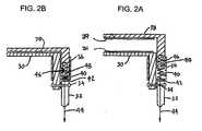
- Figures 2A and 2Bthere is seen a first embodiment of the articulated grasper jaws in accordance with one or more aspects of the present invention.
- an inner, fixed jaw member 30is pivotally secured to the grasper shaft 32 by a pin or rivet 34, although other means for pivotal mounting may be used without departing from the present invention. If articulation is not needed, the jaw member 30 can be fixed to the grasper shaft.
- a separate tubular sleeve member 36is secured to the fixed jaw 30.
- the sleeve member 36has an interior region that slidably receives the outer, movable jaw member 38.
- the fixed and movable jaw members 30 and 38have facing surfaces each of which carries a continuous elongated bipolar electrodes 31 and 39, respectively, as described above and which, for clarity, are shown in diagrammatic form.
- a compression spring 40is captured within the sleeve 36 between an extending arm 42 on the fixed jaw 30 and the movable jaw member 38. The spring 40 biases the movable jaw member 38 away from the fixed jaw member 30 to the open position shown in Figure 2A .
- a mechanismis preferably provided for remotely moving the movable jaw member 38 to the closed position shown in Figure 2B .
- an actuating memberwhich may be in the form of a length of cable 44, extends from the handle through the shaft 32.
- the cable 44can be of any flexible material, metal or plastic, single or multiple strand, and preferably has a low coefficient of friction.
- the cable 44is attached on one end to the actuator, illustrated as actuating lever 26, and on the other end to the movable jaw member 38.
- a resilient membersuch as a tension spring 46, is interposed between the cable 44 and the movable jaw 38. It may also be located at other positions along the length of the cable, as described later.
- Tension spring 46is such that it limits the pulling force that can be exerted by the actuating lever on the movable jaw to between about 2 lbs. and 20 lbs., and preferably to about a force of 7 lbs. This translates to pressure against the cardiac tissue held between the jaws of about 7 psi to 70 psi and preferably about 25 psi. As illustrated, the tension spring 46 is received in a recess 48 in the movable jaw member 38. Thus, as tension is applied to the cable 44 by actuation of the lever, the movable jaw member 38 is pulled toward the fixed jaw member 30 against the force of the compression spring 40 and to the position shown in Figure 2B .
- the tension spring 46is simultaneously stretched, thus regulating the amount of force exerted on tissue captured between the jaw members 30 and 38, and also allowing various amounts of jaw closure, depending on the thickness of the tissue being clamped. For example, with thicker tissue the tension spring allows the jaws to be spaced farther apart than when clamping thinner tissue.
- the pulling force applied by the cable to the movable jawis the product of the spring constant and the distance D, that the spring is stretched.
- pulling force exerted by the cable on the lower jawis opposed by the force exerted by the compression spring 40, which is the product of the spring constant for the compression spring K c and the distance it is compressed D c .
- the net force exerted on the heart tissue by the movable jawis the difference between these forces or the quantity (K t D t - K c D c ).
- the spring constant K c of the compression springis preferably lower than the spring constant K t of the tension spring.
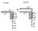
- FIG. 3A and 3BA second embodiment of the actuation mechanism for a grasper in accordance with one or more aspects of the present invention is shown in Figures 3A and 3B .
- the embodiment of Figures 3A and 3Bis similar in certain respects to structure and operation to that of Figures 2A and 2B , and the same reference numerals are used with respect to both embodiments.
- the tension spring 46is not received in the recess 48 in the movable jaw member 38. Instead, the tension spring 46 is located along the cable 44, and may be located within the shaft 32, with a first length of cable 44a connecting the tension spring 46 to the actuator lever, and a second length of cable 44b connecting the tension spring 46 to the movable jaw member 38.
- FIG. 4A and 4BA third embodiment of an actuation mechanism for a grasper embodying one or more aspects of the present invention is seen in Figures 4A and 4B , and identical reference numerals to those used in connection with Figures 2-3 are used to designate corresponding elements.
- the jawsmay be generally L-shaped with a tissue clamping portion (which mounts electrodes 31 and 39) and a right angle portion that serves to mount the jaws in their proper relationship to the shaft and/or the other jaw.
- a fixed jaw member 30is pivotally secured to the grasper shaft 32 by a pin or rivet 34 or similar device preferably formed integrally with the fixed jaw 30.
- a movable jaw member 38is slidably secured to the fixed jaw member 30 by means of a sleeve member 36 formed integrally with the movable jaw.
- a length of cable 44 in the form an endless loopextends between the handle, where it is trained or looped about a first pulley, pin or the like 50, and the fixed jaw member 30, where it is trained or looped about a second pulley or pin 52 fixed to the jaw 30.
- the cable 44is secured to an arm 54 on the movable jaw and to the actuator lever or trigger 56 at a distance D displaced from the pivot 58 for the trigger 56. Accordingly, as the trigger 56 rotates about the pivot 58, it pulls the cable 44 so that it moves about the pulleys 50 and 52 to move the movable jaw to the fixed jaw.
- a tension spring 46is interposed in the endless loop of cable 44. With a fixed maximum movement of the trigger, the tension spring serves to regulate or limit the maximum force that can exerted on tissue held between the closed jaws. As illustrated, the tension spring 46 is located within the handle. However, it could be located anywhere along the portion of the cable 44 that acts to close the jaw members. A further spring 60 is interposed between the lever 56 and the handle to bias the lever in a direction so that tension is placed on the cable 44 to return the movable jaw member 38 and lever to the open position shown in Figure 4A .
- the grasper in Figures 4A and 4Bincludes a pivoting assembly.
- a second loop of cable 62is secured on one end to the pivot pin 34 that secures the fixed jaw to the grasper shaft 32 and on its other end to a second actuator device such as trigger 64 pivotally mounted to the handle. Pivoting of the second trigger 64 with respect to the handle rotates the cable 62, and thus the pivot pin 34, to remotely change the angle of the grasper jaws 30 and 38 with respect to the shaft 32.
- the cable 62may engage the pin by friction, by meshing gears between the cable and pin, by direct attachment or other mechanical designs so that movement of the cable causes pivoting of the pin and attached jaws. While this mechanism for remotely pivoting the jaw members of the grasper is shown in connection with only selected embodiments of the invention, it is equally adaptable for use with all disclosed articulated embodiments.
- FIG. 5A and 5BA fourth embodiment of an actuation mechanism for a grasper according the present invention is shown in Figures 5A and 5B .
- the embodiment of Figures 5A and 5Bis similar to that of Figures 4A and 4B , and similar reference numerals are used for designating corresponding elements.
- the device of Figures 5A and 5Bdiffers from that of Figures 4A and 4B in that the inner jaw member comprises the fixed jaw member 30 that is pivotally secured to the grasper shaft 32, while the outer jaw member comprises the movable jaw member 38 slidably mounted to the fixed jaw member 30. Additionally, the embodiment of Figures 5A and 5B does not include the mechanism for remotely pivoting the jaw members 30 and 38 with respect to the grasper shaft 32. Otherwise, the structure, function and operation of the device of Figures 5A and 5B is substantially identical to that of Figures 4A and 4B .
- FIG. 6A and 6Bthere seen a fifth embodiment of graspers embodying one or more aspects of the present invention.
- This embodimentis similar in many respects to that shown in Figures 4A and 4B , and like reference numerals are used to designate corresponding structure.
- a mounting structurepreferably but not necessarily in the form of an elongated post or rod 66, is pivotally secured to the grasper shaft 32 by a pin 34 formed integrally with the post 66.
- the post 66has a smaller diameter or relieved terminal portion defining a shoulder 68.
- the "fixed" jaw member 70has a recessed area or bore 72 in the jaw member for slidably receiving the distal portion of the post.
- a movable jaw member 38is slidably secured to the post 66 by means of a sleeve member 36 preferably formed integrally with the movable jaw.
- a length of cable 44 in the form of an endless loopextends between pulley 50 in the handle and pulley 52 fixed to the post 66.
- the cable 44is secured to an arm 54 on the movable jaw 38 and to a trigger or lever 56 secured by pivot 58 to the handle. Accordingly, as the trigger 56 is pivoted to move the cable about the pulleys 50 and 52, and the arm 54, and consequently the movable jaw 38, are moved therewith.
- a tension spring 74is interposed between the distal end of post 66 and the fixed jaw member 70. As illustrated, the tension spring 74 resides in the hollow recess or bore 72 formed in the fixed jaw member 70. As the movable jaw member 38 is moved from the open position shown in Figure 6A and tissue is grasped between the jaws 38 and 70, the fixed jaw 70 is allowed to slide along the distal end of post 66 against the force of spring 74. When the jaws 38 and 70 are opened, the spring 74 returns the fixed jaw 70 to its original position shown in Figure 6A , with the fixed jaw 70 seated on the shoulder 68 on the relieved area of the post 66.
- jaw 70is movable to the extent permitted by biasing spring 74 which serves to limit the compressive force on the tissue.
- biasing spring 74serves to limit the compressive force on the tissue.
- "fixed jaw"is not intended to preclude any movement and is intended to include possible movement such as may occur in the embodiment of Figures 6A and 6B .
- the main movable jaw 38is the jaw directly moved by the operator via trigger 56 and cable 44.
- the fixed jaw 70moves as a result of force exerted on the tissue by movable jaw 38 and as permitted by spring 74.
- Figures 6A and 6Balso includes an actuation mechanism for pivoting the jaw members 38 and 70 with respect to the shaft 32. This mechanism is identical to that shown in Figures 4A and 4B , and, consequently, is not discussed in detail.
- the grasperincludes a shaft 32 to which a jaw mounting assembly 66 is pivotally secured, such as by a pin or rivet 34.
- the mounting assembly 66includes an integral sleeve member 36 that slidably receives both jaw members 76 and 78.
- the sleeve 36includes an elongated slot 80 that receives a tab 82 that extends from the jaw member 76. The slot 80 and tab 82 help to ensure that the jaw member 76 slides smoothly with respect to the sleeve 36 and that proper orientation of the jaw member 76 is maintained during such sliding movement.
- the mounting assemblyalso includes a post or rod 67 with a relieved or reduced diameter end portion that defines a shoulder 68 and on which the jaw member 78 is slidably seated.
- a compression spring 84is interposed between the post 66 and the jaw 78 to bias the jaw 78 away from the jaw member 76 to the open position shown in Figure 7A .
- a length of cable 44extends from the handle through the shaft 32 and is attached on one end to the actuating lever 56 and the other end to the jaw member 78.
- a compression spring 86is interposed between jaw member 76 and a bottom wall 88 on the sleeve 36.
- the compression spring 86biases the jaw member 76 toward the jaw member 78.
- the degree to which spring 86 is compressedcontrols the force exerted on tissue captured between the jaws.
- jaw 78may be referred to as the movable jaw member, as that is the jaw member directly moved by the operator via cable 44, and jaw member 76 may be referred to as the fixed jaw member, although it is movable in response to clamping to limit the force exerted on the tissue captured between the jaws as permitted by spring 86.
- FIG. 8A and 8Bthere is seen a seventh embodiment of an actuation mechanism for a graspers according to the present invention. To the extent that similar structure to that previously described is utilized in the embodiment of Figures 8A and 8B , corresponding reference numerals are used.
- a fixed jaw member 30is pivotally attached to the grasper shaft 32, such as by a pin or rivet 34.
- a movable jaw member 38is slidably secured to the fixed jaw member 30 by means of sleeve member 36.
- a length of cable 44 in the form of an endless loopextends between the handle and the fixed jaw member 30, where it is trained about pulley 52.
- the cable 44is secured to a proximal end wall 88 on the sleeve 36 and to the trigger or lever 56. Accordingly, as the trigger 56 rotates about its pivot, the cable 44 moves the sleeve 36, and consequently the movable jaw member 38, between the open and closed position shown in Figures 8A and 8B .
- a compression spring 86interposed between the movable jaw member 38 and the bottom wall 88 on the sleeve 36.
- the compression spring 86biases the movable jaw member 38 toward the fixed jaw member 30.
- the sleeve 36includes an elongated slot 80 that receives a tab 82 that extends from the movable jaw member 38. The degree to which the spring 86 is compressed controls the force exerted on tissue captured between the jaw members 30 and 38.
- FIG. 9A and 9Bwhere is seen an eighth embodiment of an actuation mechanism for a graspers according to the present invention. Again, to the extent that the structure of this embodiment is similar to the previously-described embodiments, identical reference numerals are used.
- the grasper of Figures 9A and 9Bincludes an outer, fixed jaw member 30 pivotally secured to the grasper shaft 32, such by a pin or rivet 34 or similar hinge.
- a separate slidable sleeve member 36is carried by the fixed jaw member 30, with the movable jaw member 38 being mounted to the interior of sleeve 36 so that the movable jaw member 38 and the sleeve 36 move in unison with respect to the fixed jaw 30.
- a compression spring 40is seated in a recess or bore 48 in the movable jaw member 38 and captured between the movable jaw member 38 and an arm or stop member 42 extending from the fixed jaw member 30. The spring 40 biases the assembly of the movable jaw member 38/sleeve member 36 toward the fixed jaw member 30.
- the movable jaw member 38/sleeve member 36 assemblyis maintained in the open position by an actuating device, such as cable 44, that extends from the lever 56 to the movable jaw member 38.
- an actuating devicesuch as cable 44
- tensionis released on the cable 44 that maintains the jaw members 30 and 38 in their open position against the force of the compressed spring.
- the spring 40then moves the movable jaw member 38 to the closed position.
- the force exerted on tissue held between the closed jaw members 30 and 38depends on the thickness of the tissue and the spring constant for the spring 40.
- FIG. 10A and 10Bthere is seen a ninth embodiment for an actuation mechanism for a graspers according to the present invention. Again, to the extent that the embodiment of Figures 10A and 10B employ structure previously described, the same reference numerals are used.
- a fixed jaw 30is pivotally secured to the grasper shaft 32 by such as a pin or rivet 34.
- a movable jaw member 38is slidably secured to the fixed jaw member 30 by means of slidable sleeve 36.
- An actuating devicesuch as a length of cable 44 in the form of an endless loop extends between the handle, where it is secured to the lever 56, and the fixed jaw member 38, where it is trained about pulley 52.
- the cable 44has a traveler or actuator 90 secured thereto within the fixed jaw.
- the traveler 90includes an integral arm 92 that extends outwardly from the fixed jaw member 30 into the interior of the sleeve member 36.
- a compression spring 86is interposed between the arm 92 of the traveler 90 and the movable jaw member 38.
- the spring 86biases the movable jaw member 38 toward the fixed jaw member 30. Accordingly, as the cable 44 moves about the pulley 52 in response to actuation of the lever 56, the traveler 90 moves in unison therewith to move the movable jaw member 38/sleeve 36 assembly between the open and closed positions with respect to the fixed jaw member 30.
- the sleeve 36also includes an end wall or stop member 88 that is adapted to engage the arm 92 on the traveler 90, thus limiting relative movement between the sleeve 36 and the traveler 90, and to allow opening of the jaws.
- the compression spring 86regulates the force exerted on tissue between the closed jaw members 30 and 38.
- Relative movement between the movable jaw member 38 and the sleeve 36is also accommodated.
- the sleeve 36includes an elongated slot 80 that receives a tab 82 on the movable jaw member 38. The slot 80/tab 82 limit the range of relative movement between the movable jaw member 38 and sleeve 36, as well as ensuring smooth and accurate sliding motion.
Landscapes
- Health & Medical Sciences (AREA)
- Surgery (AREA)
- Life Sciences & Earth Sciences (AREA)
- Engineering & Computer Science (AREA)
- Biomedical Technology (AREA)
- Public Health (AREA)
- Nuclear Medicine, Radiotherapy & Molecular Imaging (AREA)
- Veterinary Medicine (AREA)
- General Health & Medical Sciences (AREA)
- Heart & Thoracic Surgery (AREA)
- Medical Informatics (AREA)
- Molecular Biology (AREA)
- Animal Behavior & Ethology (AREA)
- Physics & Mathematics (AREA)
- Otolaryngology (AREA)
- Plasma & Fusion (AREA)
- Ophthalmology & Optometry (AREA)
- Surgical Instruments (AREA)
Abstract
Description
- Devices for grasping and/or clamping tissue between a pair of opposed jaw members are widely used in a variety of surgical procedures. Depending upon the procedure to be performed, it may be difficult to both gain access to and properly clamp the desired tissue due to the angle of the jaws with respect to the shaft to which they are attached. Consequently, surgical graspers have been developed in which the jaws are pivotally secured to the shaft so that the jaw assembly may be articulated with regard to the shaft. See, for example,
U.S. Patent No. 5,507,773 . DocumentUS-A-5 190 541 discloses a device as described in the preamble of claim 1. - One complication in providing for articulating jaws on a grasper is providing an actuation mechanism to move the jaws between the open and closed positions. Such an actuation mechanism must function reliably without undue interference with the articulation joint, and it is preferred that the actuation mechanism not require enlargement of the cross-sectional area of the grasper shaft.
- It is also desirable in various procedures for the jaws to provide a constant, predetermined clamping pressure that is not dependent upon the force the surgeon applies to the grasper handle. This is of particular significance where the jaws of the grasper include RF energy electrodes for ablating or cauterizing tissue. In such devices a uniform, consistent clamping pressure results in a more predictable and even application of electrosurgical current to the clamped tissue.
- Accordingly, it is one object of the present invention to provide a tissue graspers or clamping device whose jaws are pivotable with respect to their supporting shaft so that the surgeon may more easily grasp the desired tissue.
- It is also an object of another aspect of the present invention to provide a tissue grasper or clamping device with articulatable jaws that allows control of the maximum pressure that is applied to the tissue held between the jaws.
- It is a further object to provide a tissue grasper with articulatable jaws wherein the actuation mechanism for the jaws is sufficiently small that the grasper shaft can accommodate electrical conductors, sensors, and the like in addition to the actuation mechanism without necessitating undue enlargement of the cross-section of the grasper shaft.
- These objects are by way of example and not limitation of the invention claimed. As claimed, the invention may address one or more of the above objects or may address other concerns or achieve other benefits not set forth above.
- The invention is as defined in the appended set of claims.
- The present invention is generally embodied in a clamp or grasper having a handle with an elongated shaft secured thereto. First and second jaw members with opposed clamping surfaces are secured to the shaft, with one of the jaw members being movable with respect to the other jaw member. The jaw members are movable between an open position, in which the clamping surfaces are spaced apart, and a closed position, in which the clamping surfaces are spaced apart an amount less than that in the open position.
- The jaws may be activated by an actuating member(s), such as a rod or cable, that extends from the handle, through the elongated shaft and operable directly or indirectly on at least one of the jaw members for moving the jaw members between the open and closed positions. An actuator, such as a knob, lever, trigger, or other device may be secured to the handle and connected directly or indirectly to the actuating member for actuating the member. A resilient or biasing means or element, such as an elastic segment or a spring, may be associated with at least one of the first or second jaw members or the activating member to regulate or control the force exerted on tissue held between the clamping surfaces of the jaws when the jaws are in the closed position. The jaws are preferably, but not necessarily, pivotably mounted to the elongated shaft for articulation, and are pivotable with respect thereto by remote actuation.
- In one embodiment, a fixed jaw is mounted and pivotal with respect to an elongated shaft and has a sleeve member associated therewith. A movable jaw is slidably secured by the sleeve. An actuating member, which optionally may be in the form of a cable, extends from the handle through the elongated shaft and is secured to the movable jaw, with an acutator trigger pivotably secured to the handle and also connected to the cable. A resilient or biasing member, such as a spring or elastic member, is interposed between the cable and the movable jaw so that manipulation of the trigger actuates the cable to move the movable jaw between an open and closed position with respect to the fixed jaw, the spring regulating the amount of force exerted on tissue held between the jaws when the movable jaw is in the closed position. Further, an additional spring or similar resilient mean may be disposed between the jaws. The springs may have different spring constraints so that, for example, when the jaws are closing, the spring located between the jaws compresses or expands before the other spring compresses or expands.
- In a further embodiment, the movable jaw is slidably carried by the fixed jaw, and an actuating member in the form of cable extends in a loop between the handle and the fixed jaw, around a first pulley associated with the handle and a second pulley associated with the fixed jaw. The cable is secured to both an actuator, such as a trigger, and the movable jaw so that pivoting the trigger or otherwise moving the actuator moves the cable and, therefore, the movable jaw between open and closed positions with respect to the fixed jaw. A spring may be interposed along the loop of cable in order to regulate the amount of force exerted on tissue held between the jaws when the movable jaw is in the closed position.
- In a still further embodiment, a jaw mount is carried by the elongated shaft. Both first and second jaws are movably situated on the mount. An actuator, such as a trigger, is carried by the handle and an actuating member controls jaw movement. The member may comprise a cable forming a loop that extends between handle and the mount, and that is trained about a first pulley associated with the handle and a second pulley associated with the mount. The cable is secured to both the actuator and the second jaw so that movement of the actuator, e.g., pivoting the trigger, moves the second jaw between an open and closed position with respect to the first jaw. A spring or other resilient member may be interposed between the first jaw and the mount to regulate the amount force exerted on tissue held between the jaws when the second jaw is moved to the closed position.
- In another embodiment, a jaw mount is carried by the shaft with both first and second jaw members slidably carried by the mount. An actuator, e.g., a trigger is movably mounted to the handle and an actuating member, such as a cable, connects the actuator to the second jaw for moving the second jaw from an open to a closed position with respect to the first jaw. A first spring is interposed between the second jaw and the mount, which biases the second jaw toward the open position. A second spring is interposed between the first jaw and the mount for biasing the first jaw toward the second jaw and for regulating the amount of force exerted on tissue held between the jaws when the second jaw is moved to the closed position.
- In another embodiment, the fixed jaw is pivotally secured to the shaft, with a sleeve slidably secured to the fixed jaw. A movable jaw is slidably received in the sleeve and an actuating member, preferably in the form of a length of cable, forms a loop that extends between the handle and the fixed jaw. The cable is trained about a first pulley associated with the handle and a second pulley associated with the fixed jaw. The cable is secured to both an actuator, e.g., a trigger, and the sleeve so that moving the actuator (pivoting the trigger) moves the sleeve and the movable jaw carried thereby, between open and closed positions respect to the fixed jaw. A biasing member such as a spring is interposed between the sleeve and the movable jaw for biasing the movable jaw toward the fixed jaw and for regulating the amount of force exerted on tissue held between the jaws when the movable jaw is moved to the closed position.
- In a further embodiment, the fixed jaw has a sleeve slidably associated therewith and is pivotally secured to the elongated shaft. The movable jaw is carried by the sleeve, and a cable or other actuating member connects an actuator to the movable jaw for moving the movable jaw between a closed position and an open position. A spring or other biasing member is interposed between the fixed jaw and the movable jaw to bias the movable jaw toward the closed position and to regulate the amount of force exerted on tissue held between the jaws when the second jaw is in the closed position.
- In another embodiment, the grasper includes a fixed jaw with a sleeve slidably associated therewith secured to the shaft. A movable jaw is slidably received by the sleeve, and a length of cable is secured to a trigger and forms a loop extending between the handle and the fixed jaw. The cable is trained about a first pulley associated with the handle and a second pulley associated with the fixed jaw. An actuator associated with the fixed jaw and secured to the cable is movable between first and second positions with respect to the fixed jaw by pivoting the trigger member. A spring is interposed between the actuator and the movable jaw so that the actuator is moved between the first and second positions, with the movable jaw being moved between open and closed positions. The spring regulates the force exerted on tissue held between the jaws when the jaw is moved to the closed position.
- The above summaries are for introductory purposes only and are not intended to be exhaustive or exclusive of all embodiments of the present invention, or to identify any required features or aspects of the present invention.
Figure 1 is a perspective view of a tissue grasper with articulatable jaw members of the type that may incorporate the present invention.Figures 2A and 2B are fragmentary, cross-sectional views of a first embodiment of an actuation mechanism according to the present invention showing the jaws in the open and closed positions, respectively.Figures 3A and 3B are fragmentary, cross-sectional views of a second embodiment of actuation mechanism according to the present invention showing the jaws in the open and closed positions, respectively.Figures 4A and 4B are fragmentary, cross-sectional views of a third embodiment of an actuation mechanism according to the present invention showing the jaws in the open and closed positions, respectively.Figures 5A and 5B are fragmentary, cross-sectional views of a fourth embodiment of an actuation mechanism according to the present invention showing the jaws in the open and closed positions, respectively.Figures 6A and 6B are fragmentary, cross-sectional views of a fifth embodiment of an actuation mechanism according to the present invention showing the jaws in the open and closed positions, respectively.Figures 7A and 7B are fragmentary, cross-sectional views of a sixth embodiment of an actuation mechanism according to the present invention showing the jaws in the open and closed positions, respectively.Figures 8A and 8B are fragmentary, cross-sectional views of a seventh embodiment of an actuation mechanism according to the present invention showing the jaws in the open and closed positions, respectively.Figures 9A and 9B are fragmentary, cross-sectional views of an eighth embodiment of an actuation mechanism according to the present invention showing the jaws in the open and closed positions, respectively.Figures 10A and 10B are fragmentary, cross-sectional views of a ninth embodiment of an actuation mechanism according to the present invention showing the jaws in the open and closed positions, respectively.- The present invention has particular but not exclusive utility in connection with grasping or clamping devices for use in open or minimally invasive surgical procedures. The present invention has added benefits in grasping or clamping devices that include bipolar RF energy electrodes on the opposed jaw clamping surfaces, such as shown and described in
U.S. Patent Application Serial No. 10/032,378, filed October 26, 2001 . - The device disclosed in the referenced application is intended for use as a grasper which can create transmural ablation lesions in cardiac tissue for treatment, for example, of atrial fibrillation. In such treatment, ablation lesion lines may be formed in a pre-arranged pattern in the tissue of the heart to block aberrant electrical signals. The creation of this particular pattern is generally referred to as the Maze procedure. Among other things, the Maze procedure requires a series of transmural ablations or lesions to be formed on the atrium in the vicinity of the pulmonary veins.
- The present invention is generally embodied in a grasping or clamping device 10 (
Figure 1 ) that is particularly useful for creating the various transmural lesions in cardiac tissue required by the Maze and other procedures, whether a minimally invasive or open chest procedure is used for the treatment of atrial fibrillation. The clamping or grasping device will be referred to as a "grasper" for convenience only, and that term is intended to include devices for clamping, pinching, grasping tissue. Thegrasper 10 includes acord 12 for housing conductors (not shown) and for plugging into anelectrosurgical RF generator 14 to provide current to thegrasper 10. Thegenerator 14 typically includes adisplay 16 to provide a visual indication of the degree of conductance of the tissue being ablated. - The
grasper 10 includes ahandle 18 that has an elongated shaft 20 attached thereto. The shaft 20 is preferably malleable so that it can be bent by the surgeon into a configuration that more easily permits grasping of the desired tissue, although a rigid shaft may be more preferred for other procedures. Opposed parallel jaws orjaw assemblies jaws handle 18 and operatively connected to at least one of the jaws. The spacing between thejaws - Each
jaw assembly elongated electrode 28 located along the facing surface to contact the clamped tissue and provide an electrical pathway contacting the tissue to be ablated. In other words, the electrode is located on the "inside" of its jaw assembly (the "inside" being defined as the side that contacts the tissue to be ablated). - Each of the
electrodes 28 is attached to an electrically conductive means, such as a wire that runs the length of the shaft 20 and through theconductor cord 12 or coupling to theRF generator 14. - In order to ablate a narrow, long region of biological tissue with the
instrument 10, the tissue is placed between theopen instrument jaws lever 26, to close the jaws on the tissue. The operator then activates theRF generator 14 and RF energy passes through the tissue grasped between theelectrodes 28, ablating the tissue between the electrodes and forming an elongated transmural lesion in the tissue. After the completion of ablation, the operator releases the actuator, allowing the jaws to part and releasing the clamping of the tissue. Thejaw members - In accordance with one aspect of the present invention, the jaws are articulated relative to the shaft 20. In accordance with another aspect of the invention, the device includes means for limiting or controlling the clamping pressure exerted by the jaws. These aspects of the present invention may be used together or separately. With reference to
Figures 2A and 2B , there is seen a first embodiment of the articulated grasper jaws in accordance with one or more aspects of the present invention. As illustrated, an inner, fixedjaw member 30 is pivotally secured to thegrasper shaft 32 by a pin or rivet 34, although other means for pivotal mounting may be used without departing from the present invention. If articulation is not needed, thejaw member 30 can be fixed to the grasper shaft. - A separate
tubular sleeve member 36 is secured to the fixedjaw 30. Thesleeve member 36 has an interior region that slidably receives the outer,movable jaw member 38. The fixed andmovable jaw members bipolar electrodes compression spring 40 is captured within thesleeve 36 between an extendingarm 42 on the fixedjaw 30 and themovable jaw member 38. Thespring 40 biases themovable jaw member 38 away from the fixedjaw member 30 to the open position shown inFigure 2A . - A mechanism is preferably provided for remotely moving the
movable jaw member 38 to the closed position shown inFigure 2B . To this end, an actuating member, which may be in the form of a length ofcable 44, extends from the handle through theshaft 32. Thecable 44 can be of any flexible material, metal or plastic, single or multiple strand, and preferably has a low coefficient of friction. Thecable 44 is attached on one end to the actuator, illustrated as actuatinglever 26, and on the other end to themovable jaw member 38. - In order to control the force exerted on tissue captured between the
closed jaws tension spring 46, is interposed between thecable 44 and themovable jaw 38. It may also be located at other positions along the length of the cable, as described later. Tension spring 46 is such that it limits the pulling force that can be exerted by the actuating lever on the movable jaw to between about 2 lbs. and 20 lbs., and preferably to about a force of 7 lbs. This translates to pressure against the cardiac tissue held between the jaws of about 7 psi to 70 psi and preferably about 25 psi. As illustrated, thetension spring 46 is received in arecess 48 in themovable jaw member 38. Thus, as tension is applied to thecable 44 by actuation of the lever, themovable jaw member 38 is pulled toward the fixedjaw member 30 against the force of thecompression spring 40 and to the position shown inFigure 2B . Thetension spring 46 is simultaneously stretched, thus regulating the amount of force exerted on tissue captured between thejaw members cable 44 is released, thecompression spring 40 returns themovable jaw member 38 to the open position shown inFigure 2A .- For a
tension spring 46 with a spring constant of Kt, the pulling force applied by the cable to the movable jaw is the product of the spring constant and the distance D, that the spring is stretched. It should be noted that pulling force exerted by the cable on the lower jaw is opposed by the force exerted by thecompression spring 40, which is the product of the spring constant for the compression spring Kc and the distance it is compressed Dc. Thus, the net force exerted on the heart tissue by the movable jaw is the difference between these forces or the quantity (KtDt - KcDc). By selecting the spring constants and the amount of stretch or compression permitted, the force exerted on the cardiac tissue may be controlled or limited as desired. In this embodiment, the spring constant Kc of the compression spring is preferably lower than the spring constant Kt of the tension spring. - A second embodiment of the actuation mechanism for a grasper in accordance with one or more aspects of the present invention is shown in
Figures 3A and 3B . The embodiment ofFigures 3A and 3B is similar in certain respects to structure and operation to that ofFigures 2A and 2B , and the same reference numerals are used with respect to both embodiments. InFigures 3A and 3B , thetension spring 46 is not received in therecess 48 in themovable jaw member 38. Instead, thetension spring 46 is located along thecable 44, and may be located within theshaft 32, with a first length of cable 44a connecting thetension spring 46 to the actuator lever, and a second length ofcable 44b connecting thetension spring 46 to themovable jaw member 38. - A third embodiment of an actuation mechanism for a grasper embodying one or more aspects of the present invention is seen in
Figures 4A and 4B , and identical reference numerals to those used in connection withFigures 2-3 are used to designate corresponding elements. As in the above embodiments, the jaws may be generally L-shaped with a tissue clamping portion (which mountselectrodes 31 and 39) and a right angle portion that serves to mount the jaws in their proper relationship to the shaft and/or the other jaw. - A fixed
jaw member 30 is pivotally secured to thegrasper shaft 32 by a pin or rivet 34 or similar device preferably formed integrally with the fixedjaw 30. Amovable jaw member 38 is slidably secured to the fixedjaw member 30 by means of asleeve member 36 formed integrally with the movable jaw. - To effect movement of the
movable jaw member 38 between the open and closed positions, a length ofcable 44 in the form an endless loop extends between the handle, where it is trained or looped about a first pulley, pin or the like 50, and the fixedjaw member 30, where it is trained or looped about a second pulley or pin 52 fixed to thejaw 30. Thecable 44 is secured to anarm 54 on the movable jaw and to the actuator lever or trigger 56 at a distance D displaced from thepivot 58 for thetrigger 56. Accordingly, as thetrigger 56 rotates about thepivot 58, it pulls thecable 44 so that it moves about thepulleys - In keeping with another aspect of the invention, a
tension spring 46 is interposed in the endless loop ofcable 44. With a fixed maximum movement of the trigger, the tension spring serves to regulate or limit the maximum force that can exerted on tissue held between the closed jaws. As illustrated, thetension spring 46 is located within the handle. However, it could be located anywhere along the portion of thecable 44 that acts to close the jaw members. Afurther spring 60 is interposed between thelever 56 and the handle to bias the lever in a direction so that tension is placed on thecable 44 to return themovable jaw member 38 and lever to the open position shown inFigure 4A . - For remotely pivoting the
jaw members grasper shaft 32, the grasper inFigures 4A and 4B includes a pivoting assembly. To this end, a second loop ofcable 62 is secured on one end to thepivot pin 34 that secures the fixed jaw to thegrasper shaft 32 and on its other end to a second actuator device such astrigger 64 pivotally mounted to the handle. Pivoting of thesecond trigger 64 with respect to the handle rotates thecable 62, and thus thepivot pin 34, to remotely change the angle of thegrasper jaws shaft 32. Thecable 62 may engage the pin by friction, by meshing gears between the cable and pin, by direct attachment or other mechanical designs so that movement of the cable causes pivoting of the pin and attached jaws. While this mechanism for remotely pivoting the jaw members of the grasper is shown in connection with only selected embodiments of the invention, it is equally adaptable for use with all disclosed articulated embodiments. - A fourth embodiment of an actuation mechanism for a grasper according the present invention is shown in
Figures 5A and 5B . The embodiment ofFigures 5A and 5B is similar to that ofFigures 4A and 4B , and similar reference numerals are used for designating corresponding elements. The device ofFigures 5A and 5B differs from that ofFigures 4A and 4B in that the inner jaw member comprises the fixedjaw member 30 that is pivotally secured to thegrasper shaft 32, while the outer jaw member comprises themovable jaw member 38 slidably mounted to the fixedjaw member 30. Additionally, the embodiment ofFigures 5A and 5B does not include the mechanism for remotely pivoting thejaw members grasper shaft 32. Otherwise, the structure, function and operation of the device ofFigures 5A and 5B is substantially identical to that ofFigures 4A and 4B . - Turning to
Figures 6A and 6B , there seen a fifth embodiment of graspers embodying one or more aspects of the present invention. This embodiment is similar in many respects to that shown inFigures 4A and 4B , and like reference numerals are used to designate corresponding structure. A mounting structure, preferably but not necessarily in the form of an elongated post orrod 66, is pivotally secured to thegrasper shaft 32 by apin 34 formed integrally with thepost 66. Thepost 66 has a smaller diameter or relieved terminal portion defining ashoulder 68. The "fixed"jaw member 70 has a recessed area or bore 72 in the jaw member for slidably receiving the distal portion of the post. Amovable jaw member 38 is slidably secured to thepost 66 by means of asleeve member 36 preferably formed integrally with the movable jaw. - To effect movement of the
movable jaw member 38 between the open and closed positions, a length ofcable 44 in the form of an endless loop extends betweenpulley 50 in the handle andpulley 52 fixed to thepost 66. Thecable 44 is secured to anarm 54 on themovable jaw 38 and to a trigger orlever 56 secured bypivot 58 to the handle. Accordingly, as thetrigger 56 is pivoted to move the cable about thepulleys arm 54, and consequently themovable jaw 38, are moved therewith. - In order to regulate or limit the maximum force that can be exerted on tissue held between the closed jaws, a
tension spring 74 is interposed between the distal end ofpost 66 and the fixedjaw member 70. As illustrated, thetension spring 74 resides in the hollow recess or bore 72 formed in the fixedjaw member 70. As themovable jaw member 38 is moved from the open position shown inFigure 6A and tissue is grasped between thejaws jaw 70 is allowed to slide along the distal end ofpost 66 against the force ofspring 74. When thejaws spring 74 returns the fixedjaw 70 to its original position shown inFigure 6A , with the fixedjaw 70 seated on theshoulder 68 on the relieved area of thepost 66. Thus, although referred to as the fixed jaw,jaw 70 is movable to the extent permitted by biasingspring 74 which serves to limit the compressive force on the tissue. As used herein and in the claims, "fixed jaw" is not intended to preclude any movement and is intended to include possible movement such as may occur in the embodiment ofFigures 6A and 6B . As can be seen inFigures 6A and 6B , the mainmovable jaw 38 is the jaw directly moved by the operator viatrigger 56 andcable 44. The fixedjaw 70 moves as a result of force exerted on the tissue bymovable jaw 38 and as permitted byspring 74. - The embodiment of
Figures 6A and 6B also includes an actuation mechanism for pivoting thejaw members shaft 32. This mechanism is identical to that shown inFigures 4A and 4B , and, consequently, is not discussed in detail. - Turning to
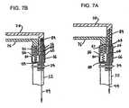
Figures 7A and 7B , there has seen a sixth embodiment of an actuation mechanism for a graspers according to the present invention. To the extent that the embodiment ofFigures 7A and 7B is similar to those embodiments previously described, like reference numerals are used to designate corresponding structure. The grasper includes ashaft 32 to which ajaw mounting assembly 66 is pivotally secured, such as by a pin orrivet 34. The mountingassembly 66 includes anintegral sleeve member 36 that slidably receives bothjaw members sleeve 36 includes anelongated slot 80 that receives atab 82 that extends from thejaw member 76. Theslot 80 andtab 82 help to ensure that thejaw member 76 slides smoothly with respect to thesleeve 36 and that proper orientation of thejaw member 76 is maintained during such sliding movement. - The mounting assembly also includes a post or
rod 67 with a relieved or reduced diameter end portion that defines ashoulder 68 and on which thejaw member 78 is slidably seated. Acompression spring 84 is interposed between thepost 66 and thejaw 78 to bias thejaw 78 away from thejaw member 76 to the open position shown inFigure 7A . To movejaw member 78 from its open to its closed position, a length ofcable 44 extends from the handle through theshaft 32 and is attached on one end to theactuating lever 56 and the other end to thejaw member 78. Thus, when thelever 56 is actuated to move thejaw member 78 to the closed position, tension is applied to thecable 44 to pull thejaw member 78 down onto the relieve portion of the post against the force of thespring 84. When tension on thecable 44 is released, thespring 84 returns thejaw member 78 back to the position shown inFigure 7A . - In order to control the force exerted on tissue captured between the
closed jaws compression spring 86 is interposed betweenjaw member 76 and abottom wall 88 on thesleeve 36. Thecompression spring 86 biases thejaw member 76 toward thejaw member 78. As thejaws spring 86 is compressed controls the force exerted on tissue captured between the jaws. Using the terminology used throughout this description, and as described above,jaw 78 may be referred to as the movable jaw member, as that is the jaw member directly moved by the operator viacable 44, andjaw member 76 may be referred to as the fixed jaw member, although it is movable in response to clamping to limit the force exerted on the tissue captured between the jaws as permitted byspring 86. - Turning to
Figures 8A and 8B , there is seen a seventh embodiment of an actuation mechanism for a graspers according to the present invention. To the extent that similar structure to that previously described is utilized in the embodiment ofFigures 8A and 8B , corresponding reference numerals are used. - In
Figures 8A and 8B , a fixedjaw member 30 is pivotally attached to thegrasper shaft 32, such as by a pin orrivet 34. Amovable jaw member 38 is slidably secured to the fixedjaw member 30 by means ofsleeve member 36. To effect movement of themovable jaw member 38 between the open and closed positions, a length ofcable 44 in the form of an endless loop extends between the handle and the fixedjaw member 30, where it is trained aboutpulley 52. Thecable 44 is secured to aproximal end wall 88 on thesleeve 36 and to the trigger orlever 56. Accordingly, as thetrigger 56 rotates about its pivot, thecable 44 moves thesleeve 36, and consequently themovable jaw member 38, between the open and closed position shown inFigures 8A and 8B . - In order to control the force exerted on tissue captured between the
closed jaw members compression spring 86 interposed between themovable jaw member 38 and thebottom wall 88 on thesleeve 36. Thecompression spring 86 biases themovable jaw member 38 toward the fixedjaw member 30. As thejaw members sleeve 36 against the force of thespring 86. To ensure a smooth and accurate sliding motion, thesleeve 36 includes anelongated slot 80 that receives atab 82 that extends from themovable jaw member 38. The degree to which thespring 86 is compressed controls the force exerted on tissue captured between thejaw members - Turning to
Figures 9A and 9B , where is seen an eighth embodiment of an actuation mechanism for a graspers according to the present invention. Again, to the extent that the structure of this embodiment is similar to the previously-described embodiments, identical reference numerals are used. - The grasper of
Figures 9A and 9B includes an outer, fixedjaw member 30 pivotally secured to thegrasper shaft 32, such by a pin or rivet 34 or similar hinge. A separateslidable sleeve member 36 is carried by the fixedjaw member 30, with themovable jaw member 38 being mounted to the interior ofsleeve 36 so that themovable jaw member 38 and thesleeve 36 move in unison with respect to the fixedjaw 30. Acompression spring 40 is seated in a recess or bore 48 in themovable jaw member 38 and captured between themovable jaw member 38 and an arm or stopmember 42 extending from the fixedjaw member 30. Thespring 40 biases the assembly of themovable jaw member 38/sleeve member 36 toward the fixedjaw member 30. Themovable jaw member 38/sleeve member 36 assembly is maintained in the open position by an actuating device, such ascable 44, that extends from thelever 56 to themovable jaw member 38. When the lever is actuated, tension is released on thecable 44 that maintains thejaw members spring 40 then moves themovable jaw member 38 to the closed position. The force exerted on tissue held between theclosed jaw members spring 40. - Turning to
Figures 10A and 10B , there is seen a ninth embodiment for an actuation mechanism for a graspers according to the present invention. Again, to the extent that the embodiment ofFigures 10A and 10B employ structure previously described, the same reference numerals are used. - A fixed
jaw 30 is pivotally secured to thegrasper shaft 32 by such as a pin orrivet 34. Amovable jaw member 38 is slidably secured to the fixedjaw member 30 by means ofslidable sleeve 36. An actuating device such as a length ofcable 44 in the form of an endless loop extends between the handle, where it is secured to thelever 56, and the fixedjaw member 38, where it is trained aboutpulley 52. Thecable 44 has a traveler oractuator 90 secured thereto within the fixed jaw. Thetraveler 90 includes anintegral arm 92 that extends outwardly from the fixedjaw member 30 into the interior of thesleeve member 36. - A
compression spring 86 is interposed between thearm 92 of thetraveler 90 and themovable jaw member 38. Thespring 86 biases themovable jaw member 38 toward the fixedjaw member 30. Accordingly, as thecable 44 moves about thepulley 52 in response to actuation of thelever 56, thetraveler 90 moves in unison therewith to move themovable jaw member 38/sleeve 36 assembly between the open and closed positions with respect to the fixedjaw member 30. - The
sleeve 36 also includes an end wall or stopmember 88 that is adapted to engage thearm 92 on thetraveler 90, thus limiting relative movement between thesleeve 36 and thetraveler 90, and to allow opening of the jaws. When in the closed position, thecompression spring 86 regulates the force exerted on tissue between theclosed jaw members movable jaw member 38 and thesleeve 36 is also accommodated. To this end, thesleeve 36 includes anelongated slot 80 that receives atab 82 on themovable jaw member 38. Theslot 80/tab 82 limit the range of relative movement between themovable jaw member 38 andsleeve 36, as well as ensuring smooth and accurate sliding motion. - While the invention has been described in terms of certain preferred embodiments, there is no intention to limit the invention to the same. Instead, the invention is defined by the scope of the following claims.
Claims (11)
- A device for clamping tissue comprising:a handle (18),an elongated shaft (20) having proximal and distal ends and being secured to the handle at the proximal end;first (30) and second (38) jaw members carried at the distal end of the shaft and having opposed clamping surfaces;the first jaw member being a fixed jaw member mounted to the shaft and having a sleeve (36) associated therewith;the second jaw member being slidably secured to the first jaw member by the sleeve, so the jaw members can be moved between an open position in which the clamping surfaces are spaced apart and a closed position in which the clamping surfaces are spaced apart an amount less than that in the open position;an actuating member (32) secured to the handle for exerting a force and a cable (44) extending from the actuating member through the elongated shaft to the second, movable jaw member for moving the jaw members between the open and closed positions; andcharacterized in that the device comprisesa first resilient member (46) comprising a spring interposed between the cable and the movable jaw member for limiting the amount of force exerted on tissue held between the clamping surfaces of the jaws when the jaws are in the closed position.
- The device of Claim 1, wherein the first jaw member is pivotally secured to the elongated shaft.
- The device of Claim 1, further comprising a second resilient member operable to bias the second jaw member to the open position.
- The device of Claim 1, wherein the shaft is malleable so that it may be formed by a user into a desired shape.
- The device of Claim 1, wherein the clamping surface of each of the first and second jaw members includes an elongated electrode.
- The device of claim 2, wherein the clamping surface of each of the first and second jaw members includes an elongated electrode.
- The device of claim 2, wherein the first jaw is pivotable with respect to the elongated shaft by remote actuation.
- The device of claim 1, wherein the fixed jaw is pivotally mounted to the shaft.
- The device of claim 1, further comprising a second spring interposed between the fixed jaw and the moveable jaw to bias the moveable jaw toward its open position.
- The device of Claim 1, wherein the actuating member comprises a trigger pivotally fixed to the handle and a first length of the cable connects the trigger to the first spring and the first spring is connected directly to the moveable jaw.
- The device of Claim 1, wherein the actuating member comprises a trigger pivotally fixed to the handle and a first length of the cable connects the trigger to the first spring and a second length of the cable connects the spring to the moveable jaw, the first spring being located within the elongated shaft or handle.
Applications Claiming Priority (3)
| Application Number | Priority Date | Filing Date | Title |
|---|---|---|---|
| US263386 | 2002-10-02 | ||
| US10/263,386US7291161B2 (en) | 2002-10-02 | 2002-10-02 | Articulated clamping member |
| PCT/US2003/030442WO2004030553A1 (en) | 2002-10-02 | 2003-09-26 | Articulated clamping member |
Publications (3)
| Publication Number | Publication Date |
|---|---|
| EP1549239A1 EP1549239A1 (en) | 2005-07-06 |
| EP1549239A4 EP1549239A4 (en) | 2006-03-22 |
| EP1549239B1true EP1549239B1 (en) | 2011-09-14 |
Family
ID=32041981
Family Applications (1)
| Application Number | Title | Priority Date | Filing Date |
|---|---|---|---|
| EP03756874AExpired - LifetimeEP1549239B1 (en) | 2002-10-02 | 2003-09-26 | Articulated clamping member |
Country Status (4)
| Country | Link |
|---|---|
| US (1) | US7291161B2 (en) |
| EP (1) | EP1549239B1 (en) |
| AU (1) | AU2003299197A1 (en) |
| WO (1) | WO2004030553A1 (en) |
Families Citing this family (81)
| Publication number | Priority date | Publication date | Assignee | Title |
|---|---|---|---|---|
| US7364577B2 (en) | 2002-02-11 | 2008-04-29 | Sherwood Services Ag | Vessel sealing system |
| US7226446B1 (en) | 1999-05-04 | 2007-06-05 | Dinesh Mody | Surgical microwave ablation assembly |
| US7033352B1 (en) | 2000-01-18 | 2006-04-25 | Afx, Inc. | Flexible ablation instrument |
| ES2262639T3 (en) | 2001-04-06 | 2006-12-01 | Sherwood Services Ag | SHUTTER AND DIVIDER OF GLASSES WITH BUMPER MEMBERS N OCONDUCTIVES. |
| US9072522B2 (en)* | 2001-12-04 | 2015-07-07 | Atricure, Inc. | Adjustable clamp systems and methods |
| US7192427B2 (en)* | 2002-02-19 | 2007-03-20 | Afx, Inc. | Apparatus and method for assessing transmurality of a tissue ablation |
| US7931649B2 (en) | 2002-10-04 | 2011-04-26 | Tyco Healthcare Group Lp | Vessel sealing instrument with electrical cutting mechanism |
| US7819860B2 (en)* | 2003-06-10 | 2010-10-26 | Medtronic Cryocath Lp | Surgical clamp having trasmurality assessment capabilities |
| US8398632B1 (en)* | 2003-06-10 | 2013-03-19 | Medtronic Cryocath Lp | Surgical clamp having treatment elements |
| US7044946B2 (en) | 2003-06-10 | 2006-05-16 | Cryocath Technologies Inc. | Surgical clamp having treatment elements |
| EP2474272B1 (en)* | 2003-06-17 | 2020-11-04 | Covidien LP | Surgical stapling device |
| US7367976B2 (en) | 2003-11-17 | 2008-05-06 | Sherwood Services Ag | Bipolar forceps having monopolar extension |
| DE102004013530B4 (en)* | 2004-03-19 | 2011-02-17 | Sutter Medizintechnik Gmbh | Bipolar coagulation forceps |
| JP4481052B2 (en)* | 2004-03-26 | 2010-06-16 | オリンパス株式会社 | Surgical grasper |
| DE102004032450B4 (en)* | 2004-06-29 | 2008-01-17 | Otten, Gert, Prof. Dr.med. | Surgical device for clamping organic tissue, in particular blood vessels |
| US8876820B2 (en)* | 2004-10-20 | 2014-11-04 | Atricure, Inc. | Surgical clamp |
| US7582086B2 (en) | 2004-10-20 | 2009-09-01 | Atricure, Inc. | Surgical clamp |
| US7909823B2 (en) | 2005-01-14 | 2011-03-22 | Covidien Ag | Open vessel sealing instrument |
| DE202005004773U1 (en)* | 2005-03-24 | 2005-06-02 | Sutter Medizintechnik Gmbh | Coagulation forceps with a tubular shaft |
| US7918848B2 (en)* | 2005-03-25 | 2011-04-05 | Maquet Cardiovascular, Llc | Tissue welding and cutting apparatus and method |
| US7491202B2 (en)* | 2005-03-31 | 2009-02-17 | Covidien Ag | Electrosurgical forceps with slow closure sealing plates and method of sealing tissue |
| US8728072B2 (en) | 2005-05-12 | 2014-05-20 | Aesculap Ag | Electrocautery method and apparatus |
| US9339323B2 (en) | 2005-05-12 | 2016-05-17 | Aesculap Ag | Electrocautery method and apparatus |
| US7803156B2 (en)* | 2006-03-08 | 2010-09-28 | Aragon Surgical, Inc. | Method and apparatus for surgical electrocautery |
| US20060259035A1 (en)* | 2005-05-12 | 2006-11-16 | Camran Nezhat | Method and Apparatus for Performing a Surgical Procedure |
| US7942874B2 (en) | 2005-05-12 | 2011-05-17 | Aragon Surgical, Inc. | Apparatus for tissue cauterization |
| US8696662B2 (en)* | 2005-05-12 | 2014-04-15 | Aesculap Ag | Electrocautery method and apparatus |
| US7922953B2 (en) | 2005-09-30 | 2011-04-12 | Covidien Ag | Method for manufacturing an end effector assembly |
| CA2561034C (en)* | 2005-09-30 | 2014-12-09 | Sherwood Services Ag | Flexible endoscopic catheter with an end effector for coagulating and transfecting tissue |
| EP1986559B1 (en) | 2006-02-24 | 2012-03-28 | Terumo Kabushiki Kaisha | Pfo closing device |
| US8574229B2 (en)* | 2006-05-02 | 2013-11-05 | Aesculap Ag | Surgical tool |
| US9924998B2 (en)* | 2007-01-12 | 2018-03-27 | Atricure, Inc. | Ablation system, clamp and method of use |
| US8028882B2 (en) | 2007-05-01 | 2011-10-04 | Tyco Healthcare Group | Anvil position detector for a surgical stapler |
| US20090077156A1 (en)* | 2007-09-14 | 2009-03-19 | Srinivas Raghav Kashyap | Efficient constraint monitoring using adaptive thresholds |
| US8641710B2 (en) | 2007-11-12 | 2014-02-04 | Intermountain Invention Management, Llc | Magnetically coupling devices for mapping and/or ablating |
| US8100899B2 (en) | 2007-11-12 | 2012-01-24 | Ihc Intellectual Asset Management, Llc | Combined endocardial and epicardial magnetically coupled ablation device |
| US8870867B2 (en) | 2008-02-06 | 2014-10-28 | Aesculap Ag | Articulable electrosurgical instrument with a stabilizable articulation actuator |
| ES2442241T3 (en) | 2008-03-31 | 2014-02-10 | Applied Medical Resources Corporation | Electrosurgical system with a switching mechanism |
| US9402680B2 (en) | 2008-05-27 | 2016-08-02 | Maquet Cardiovasular, Llc | Surgical instrument and method |
| US8142473B2 (en) | 2008-10-03 | 2012-03-27 | Tyco Healthcare Group Lp | Method of transferring rotational motion in an articulating surgical instrument |
| US8016827B2 (en) | 2008-10-09 | 2011-09-13 | Tyco Healthcare Group Lp | Apparatus, system, and method for performing an electrosurgical procedure |
| US8114122B2 (en) | 2009-01-13 | 2012-02-14 | Tyco Healthcare Group Lp | Apparatus, system, and method for performing an electrosurgical procedure |
| US7984665B1 (en)* | 2009-03-25 | 2011-07-26 | Robertson Kenny D | Hot stick switch head |
| US8444642B2 (en)* | 2009-04-03 | 2013-05-21 | Device Evolutions, Llc | Laparoscopic nephrectomy device |
| US8187273B2 (en) | 2009-05-07 | 2012-05-29 | Tyco Healthcare Group Lp | Apparatus, system, and method for performing an electrosurgical procedure |
| US8246618B2 (en) | 2009-07-08 | 2012-08-21 | Tyco Healthcare Group Lp | Electrosurgical jaws with offset knife |
| US8343150B2 (en)* | 2009-07-15 | 2013-01-01 | Covidien Lp | Mechanical cycling of seal pressure coupled with energy for tissue fusion |
| US8133254B2 (en) | 2009-09-18 | 2012-03-13 | Tyco Healthcare Group Lp | In vivo attachable and detachable end effector assembly and laparoscopic surgical instrument and methods therefor |
| US8112871B2 (en) | 2009-09-28 | 2012-02-14 | Tyco Healthcare Group Lp | Method for manufacturing electrosurgical seal plates |
| US11229479B2 (en)* | 2009-12-18 | 2022-01-25 | Atricure, Inc. | Adjustable clamp systems and methods |
| ES2662543T3 (en) | 2010-01-26 | 2018-04-06 | Artack Medical (2013) Ltd. | Articulated medical instrument |
| US8556929B2 (en)* | 2010-01-29 | 2013-10-15 | Covidien Lp | Surgical forceps capable of adjusting seal plate width based on vessel size |
| ES2436516T3 (en) | 2010-02-04 | 2014-01-02 | Aesculap Ag | Laparoscopic radiofrequency surgical device |
| US8419727B2 (en) | 2010-03-26 | 2013-04-16 | Aesculap Ag | Impedance mediated power delivery for electrosurgery |
| US8827992B2 (en) | 2010-03-26 | 2014-09-09 | Aesculap Ag | Impedance mediated control of power delivery for electrosurgery |
| US11278345B2 (en)* | 2010-05-25 | 2022-03-22 | Covidien Lp | Accurate jaw closure force in a catheter based instrument |
| US9173698B2 (en) | 2010-09-17 | 2015-11-03 | Aesculap Ag | Electrosurgical tissue sealing augmented with a seal-enhancing composition |
| AU2011308509B8 (en) | 2010-10-01 | 2015-04-02 | Applied Medical Resources Corporation | Electrosurgical instrument |
| WO2012068004A1 (en) | 2010-11-15 | 2012-05-24 | Ethicon Endo-Surgery, Inc. | Laparoscopic suturing instrument with perpendicular eccentric needle motion |
| US9113940B2 (en) | 2011-01-14 | 2015-08-25 | Covidien Lp | Trigger lockout and kickback mechanism for surgical instruments |
| US9339327B2 (en) | 2011-06-28 | 2016-05-17 | Aesculap Ag | Electrosurgical tissue dissecting device |
| USD680220S1 (en) | 2012-01-12 | 2013-04-16 | Coviden IP | Slider handle for laparoscopic device |
| JP6336451B2 (en) | 2012-09-26 | 2018-06-06 | アエスキュラップ アーゲー | Tissue cutting and sealing device |
| USD713959S1 (en)* | 2013-02-01 | 2014-09-23 | Cardiomedical Gmbh | Surgical clamp |
| USD713526S1 (en)* | 2013-07-26 | 2014-09-16 | Cardiomedical Gmbh | Surgical clamp |
| US9700312B2 (en)* | 2014-01-28 | 2017-07-11 | Covidien Lp | Surgical apparatus |
| WO2015176074A2 (en) | 2014-05-16 | 2015-11-19 | Applied Medical Resources Corporation | Electrosurgical system |
| JP6735272B2 (en) | 2014-05-30 | 2020-08-05 | アプライド メディカル リソーシーズ コーポレイション | Electrosurgical sealing and incision system |
| KR102545505B1 (en) | 2014-12-23 | 2023-06-20 | 어플라이드 메디컬 리소시스 코포레이션 | Bipolar Electrosurgical Sealers and Dividers |
| USD748259S1 (en) | 2014-12-29 | 2016-01-26 | Applied Medical Resources Corporation | Electrosurgical instrument |
| US10987159B2 (en) | 2015-08-26 | 2021-04-27 | Covidien Lp | Electrosurgical end effector assemblies and electrosurgical forceps configured to reduce thermal spread |
| WO2017062516A1 (en) | 2015-10-05 | 2017-04-13 | Flexdex, Inc. | Medical devices having smoothly articulating multi-cluster joints |
| US11896255B2 (en)* | 2015-10-05 | 2024-02-13 | Flexdex, Inc. | End-effector jaw closure transmission systems for remote access tools |
| US10213250B2 (en) | 2015-11-05 | 2019-02-26 | Covidien Lp | Deployment and safety mechanisms for surgical instruments |
| WO2017147607A1 (en) | 2016-02-25 | 2017-08-31 | Flexdex, Inc. | Parallel kinematic apparatuses |
| EP3520727B1 (en)* | 2016-09-29 | 2022-03-30 | National University Corporation Shiga University OF Medical Science | Tissue joiner |
| US11564733B2 (en)* | 2018-01-17 | 2023-01-31 | Covidien Lp | Surgical instruments incorporating ultrasonic and electrosurgical functionality |
| JP7610777B2 (en) | 2018-09-05 | 2025-01-09 | アプライド メディカル リソーシーズ コーポレイション | Electrosurgical Generator Control System |
| CA3120184A1 (en) | 2018-11-15 | 2020-05-22 | Applied Medical Resources Corporation | Laparoscopic grasper with force-limiting grasping mechanism |
| US11696796B2 (en) | 2018-11-16 | 2023-07-11 | Applied Medical Resources Corporation | Electrosurgical system |
| JP2022525823A (en) | 2019-01-10 | 2022-05-20 | アトリキュア, インコーポレイテッド | Surgical forceps |
Family Cites Families (284)
| Publication number | Priority date | Publication date | Assignee | Title |
|---|---|---|---|---|
| US1127948A (en) | 1914-12-31 | 1915-02-09 | Reinhold H Wappler | Cystoscope. |
| US2004559A (en) | 1932-11-22 | 1935-06-11 | Wappler Frederick Charles | Method and instrument for electrosurgical treatment of tissue |
| US3470875A (en) | 1966-10-06 | 1969-10-07 | Alfred A Johnson | Surgical clamping and suturing instrument |
| US3636943A (en)* | 1967-10-27 | 1972-01-25 | Ultrasonic Systems | Ultrasonic cauterization |
| US3630207A (en) | 1969-08-08 | 1971-12-28 | Cutter Lab | Pericardial catheter |
| US4058126A (en)* | 1973-08-02 | 1977-11-15 | Leveen Harry H | Device for the fracture of the blood vessel lining |
| US3868957A (en)* | 1973-10-03 | 1975-03-04 | Regents State Of Florida Board | Vascular clamp |
| US3901242A (en) | 1974-05-30 | 1975-08-26 | Storz Endoskop Gmbh | Electric surgical instrument |
| US4043342A (en) | 1974-08-28 | 1977-08-23 | Valleylab, Inc. | Electrosurgical devices having sesquipolar electrode structures incorporated therein |
| US4106508A (en)* | 1976-08-31 | 1978-08-15 | Richard Barnard Berlin | Clamp device |
| US4312337A (en) | 1980-09-08 | 1982-01-26 | Donohue Brian T | Cannula and drill guide apparatus |
| US4353371A (en) | 1980-09-24 | 1982-10-12 | Cosman Eric R | Longitudinally, side-biting, bipolar coagulating, surgical instrument |
| US5116332A (en) | 1981-03-11 | 1992-05-26 | Lottick Edward A | Electrocautery hemostat |
| US4492231A (en) | 1982-09-17 | 1985-01-08 | Auth David C | Non-sticking electrocautery system and forceps |
| US5085657A (en) | 1983-03-14 | 1992-02-04 | Ben Simhon Haim | Electrosurgical instrument |
| US5451223B1 (en) | 1983-03-14 | 1998-11-03 | Ben Simhon Haim | Electrosurgical instrument |
| US4590934A (en) | 1983-05-18 | 1986-05-27 | Jerry L. Malis | Bipolar cutter/coagulator |
| DE3423356C2 (en) | 1984-06-25 | 1986-06-26 | Berchtold Medizin-Elektronik GmbH & Co, 7200 Tuttlingen | Electrosurgical high frequency cutting instrument |
| DE3501863C2 (en) | 1985-01-22 | 1987-02-19 | Hermann 7803 Gundelfingen Sutter | Bipolar coagulation instrument |
| US4940064A (en) | 1986-11-14 | 1990-07-10 | Desai Jawahar M | Catheter for mapping and ablation and method therefor |
| US5231995A (en) | 1986-11-14 | 1993-08-03 | Desai Jawahar M | Method for catheter mapping and ablation |
| US4848338A (en) | 1987-01-20 | 1989-07-18 | Minnesota Mining And Manufacturing Company | Hydraulically operated surgical instrument |
| US4802475A (en) | 1987-06-22 | 1989-02-07 | Weshahy Ahmed H A G | Methods and apparatus of applying intra-lesional cryotherapy |
| US5033477A (en) | 1987-11-13 | 1991-07-23 | Thomas J. Fogarty | Method and apparatus for providing intrapericardial access and inserting intrapericardial electrodes |
| US5147355A (en) | 1988-09-23 | 1992-09-15 | Brigham And Womens Hospital | Cryoablation catheter and method of performing cryoablation |
| US4976721A (en) | 1988-12-14 | 1990-12-11 | The Research Foundation Of State University Of New York | Surgical clamping device |
| US5125928A (en) | 1989-04-13 | 1992-06-30 | Everest Medical Corporation | Ablation catheter with selectively deployable electrodes |
| US5451227A (en) | 1989-04-24 | 1995-09-19 | Michaelson; Gary K. | Thin foot plate multi bite rongeur |
| US5009661A (en) | 1989-04-24 | 1991-04-23 | Michelson Gary K | Protective mechanism for surgical rongeurs |
| US5071428A (en) | 1989-09-08 | 1991-12-10 | Ventritex, Inc. | Method and apparatus for providing intrapericardial access and inserting intrapericardial electrodes |
| US5893863A (en) | 1989-12-05 | 1999-04-13 | Yoon; Inbae | Surgical instrument with jaws and movable internal hook member for use thereof |
| US5013312A (en) | 1990-03-19 | 1991-05-07 | Everest Medical Corporation | Bipolar scalpel for harvesting internal mammary artery |
| DE4010775A1 (en) | 1990-04-04 | 1991-10-17 | Wolf Gmbh Richard | MEDICAL PLIERS |
| US5087243A (en) | 1990-06-18 | 1992-02-11 | Boaz Avitall | Myocardial iontophoresis |
| US5044947A (en) | 1990-06-29 | 1991-09-03 | Ormco Corporation | Orthodontic archwire and method of moving teeth |
| US5083565A (en) | 1990-08-03 | 1992-01-28 | Everest Medical Corporation | Electrosurgical instrument for ablating endocardial tissue |
| ATE197906T1 (en) | 1990-10-09 | 2000-12-15 | Medtronic Inc | DEVICE FOR MANIPULATING MATTER |
| DE4032471C2 (en) | 1990-10-12 | 1997-02-06 | Delma Elektro Med App | Electrosurgical device |
| US5190541A (en)* | 1990-10-17 | 1993-03-02 | Boston Scientific Corporation | Surgical instrument and method |
| JP3073519B2 (en) | 1990-11-17 | 2000-08-07 | 任天堂株式会社 | Display range control device and external memory device |
| US5217460A (en) | 1991-03-22 | 1993-06-08 | Knoepfler Dennis J | Multiple purpose forceps |
| US5571215A (en) | 1993-02-22 | 1996-11-05 | Heartport, Inc. | Devices and methods for intracardiac procedures |
| US5452733A (en) | 1993-02-22 | 1995-09-26 | Stanford Surgical Technologies, Inc. | Methods for performing thoracoscopic coronary artery bypass |
| US5242458A (en) | 1991-10-15 | 1993-09-07 | Ethicon, Inc. | Suture needle holder for endoscopic use |
| US5250047A (en) | 1991-10-21 | 1993-10-05 | Everest Medical Corporation | Bipolar laparoscopic instrument with replaceable electrode tip assembly |
| US5269326A (en) | 1991-10-24 | 1993-12-14 | Georgetown University | Method for transvenously accessing the pericardial space via the right auricle for medical procedures |
| US5531744A (en) | 1991-11-01 | 1996-07-02 | Medical Scientific, Inc. | Alternative current pathways for bipolar surgical cutting tool |
| US5207691A (en) | 1991-11-01 | 1993-05-04 | Medical Scientific, Inc. | Electrosurgical clip applicator |
| US5222501A (en) | 1992-01-31 | 1993-06-29 | Duke University | Methods for the diagnosis and ablation treatment of ventricular tachycardia |
| US5327905A (en) | 1992-02-14 | 1994-07-12 | Boaz Avitall | Biplanar deflectable catheter for arrhythmogenic tissue ablation |
| US5354297A (en) | 1992-02-14 | 1994-10-11 | Boaz Avitall | Biplanar deflectable catheter for arrhythmogenic tissue ablation |
| US5263493A (en) | 1992-02-24 | 1993-11-23 | Boaz Avitall | Deflectable loop electrode array mapping and ablation catheter for cardiac chambers |
| US5242441A (en) | 1992-02-24 | 1993-09-07 | Boaz Avitall | Deflectable catheter with rotatable tip electrode |
| US5555883A (en) | 1992-02-24 | 1996-09-17 | Avitall; Boaz | Loop electrode array mapping and ablation catheter for cardiac chambers |
| US5281216A (en) | 1992-03-31 | 1994-01-25 | Valleylab, Inc. | Electrosurgical bipolar treating apparatus |
| US5254130A (en) | 1992-04-13 | 1993-10-19 | Raychem Corporation | Surgical device |
| US5620459A (en) | 1992-04-15 | 1997-04-15 | Microsurge, Inc. | Surgical instrument |
| US5318589A (en) | 1992-04-15 | 1994-06-07 | Microsurge, Inc. | Surgical instrument for endoscopic surgery |
| US5281215A (en) | 1992-04-16 | 1994-01-25 | Implemed, Inc. | Cryogenic catheter |
| US5423807A (en) | 1992-04-16 | 1995-06-13 | Implemed, Inc. | Cryogenic mapping and ablation catheter |
| US5443463A (en) | 1992-05-01 | 1995-08-22 | Vesta Medical, Inc. | Coagulating forceps |
| US5389072A (en) | 1992-06-05 | 1995-02-14 | Mircor Biomedical, Inc. | Mechanism for manipulating a tool and flexible elongate device using the same |
| WO1994002077A2 (en) | 1992-07-15 | 1994-02-03 | Angelase, Inc. | Ablation catheter system |
| CA2104345A1 (en) | 1992-09-02 | 1994-03-03 | David T. Green | Surgical clamp apparatus |
| US5250075A (en) | 1992-09-02 | 1993-10-05 | Behnam Badie | Bayonet sucker forceps |
| US5293869A (en) | 1992-09-25 | 1994-03-15 | Ep Technologies, Inc. | Cardiac probe with dynamic support for maintaining constant surface contact during heart systole and diastole |
| US5687737A (en) | 1992-10-09 | 1997-11-18 | Washington University | Computerized three-dimensional cardiac mapping with interactive visual displays |
| US6068653A (en) | 1992-11-13 | 2000-05-30 | Scimed Life Systems, Inc. | Electrophysiology catheter device |
| US5357956A (en) | 1992-11-13 | 1994-10-25 | American Cardiac Ablation Co., Inc. | Apparatus and method for monitoring endocardial signal during ablation |
| US5441483A (en) | 1992-11-16 | 1995-08-15 | Avitall; Boaz | Catheter deflection control |
| US5403312A (en) | 1993-07-22 | 1995-04-04 | Ethicon, Inc. | Electrosurgical hemostatic device |
| US5807393A (en) | 1992-12-22 | 1998-09-15 | Ethicon Endo-Surgery, Inc. | Surgical tissue treating device with locking mechanism |
| US6010531A (en) | 1993-02-22 | 2000-01-04 | Heartport, Inc. | Less-invasive devices and methods for cardiac valve surgery |
| US5797960A (en) | 1993-02-22 | 1998-08-25 | Stevens; John H. | Method and apparatus for thoracoscopic intracardiac procedures |
| US6161543A (en) | 1993-02-22 | 2000-12-19 | Epicor, Inc. | Methods of epicardial ablation for creating a lesion around the pulmonary veins |
| JPH06261043A (en) | 1993-03-05 | 1994-09-16 | Hitachi Ltd | Wireless LAN system and control method thereof |
| US5445638B1 (en) | 1993-03-08 | 1998-05-05 | Everest Medical Corp | Bipolar coagulation and cutting forceps |
| US5306234A (en) | 1993-03-23 | 1994-04-26 | Johnson W Dudley | Method for closing an atrial appendage |
| US5702359A (en) | 1995-06-06 | 1997-12-30 | Genetronics, Inc. | Needle electrodes for mediated delivery of drugs and genes |
| DE4313903C1 (en) | 1993-04-28 | 1994-09-15 | Winter & Ibe Olympus | Surgical instrument with jaws |
| GB9314391D0 (en) | 1993-07-12 | 1993-08-25 | Gyrus Medical Ltd | A radio frequency oscillator and an electrosurgical generator incorporating such an oscillator |
| US5709680A (en) | 1993-07-22 | 1998-01-20 | Ethicon Endo-Surgery, Inc. | Electrosurgical hemostatic device |
| US5810811A (en) | 1993-07-22 | 1998-09-22 | Ethicon Endo-Surgery, Inc. | Electrosurgical hemostatic device |
| US5688270A (en) | 1993-07-22 | 1997-11-18 | Ethicon Endo-Surgery,Inc. | Electrosurgical hemostatic device with recessed and/or offset electrodes |
| US5693051A (en) | 1993-07-22 | 1997-12-02 | Ethicon Endo-Surgery, Inc. | Electrosurgical hemostatic device with adaptive electrodes |
| US5980516A (en) | 1993-08-27 | 1999-11-09 | Medtronic, Inc. | Method and apparatus for R-F ablation |
| US5807395A (en) | 1993-08-27 | 1998-09-15 | Medtronic, Inc. | Method and apparatus for RF ablation and hyperthermia |
| US5431649A (en) | 1993-08-27 | 1995-07-11 | Medtronic, Inc. | Method and apparatus for R-F ablation |
| US5718703A (en) | 1993-09-17 | 1998-02-17 | Origin Medsystems, Inc. | Method and apparatus for small needle electrocautery |
| US5496312A (en) | 1993-10-07 | 1996-03-05 | Valleylab Inc. | Impedance and temperature generator control |
| US5429636A (en) | 1993-10-08 | 1995-07-04 | United States Surgical Corporation | Conductive body tissue penetrating device |
| US5582609A (en) | 1993-10-14 | 1996-12-10 | Ep Technologies, Inc. | Systems and methods for forming large lesions in body tissue using curvilinear electrode elements |
| US5656028A (en) | 1993-11-03 | 1997-08-12 | Daig Corporation | Process for the nonsurgical mapping and/or treatment of ectopic atrial tachycardia using a guiding introducer |
| US5564440A (en) | 1993-11-03 | 1996-10-15 | Daig Corporation | Method for mopping and/or ablation of anomalous conduction pathways |
| US5575766A (en) | 1993-11-03 | 1996-11-19 | Daig Corporation | Process for the nonsurgical mapping and treatment of atrial arrhythmia using catheters guided by shaped guiding introducers |
| US5536267A (en) | 1993-11-08 | 1996-07-16 | Zomed International | Multiple electrode ablation apparatus |
| US5472441A (en) | 1993-11-08 | 1995-12-05 | Zomed International | Device for treating cancer and non-malignant tumors and methods |
| US5683384A (en) | 1993-11-08 | 1997-11-04 | Zomed | Multiple antenna ablation apparatus |
| US5928229A (en) | 1993-11-08 | 1999-07-27 | Rita Medical Systems, Inc. | Tumor ablation apparatus |
| US5728143A (en) | 1995-08-15 | 1998-03-17 | Rita Medical Systems, Inc. | Multiple antenna ablation apparatus and method |
| US5465716A (en) | 1993-11-22 | 1995-11-14 | Avitall; Boaz | Catheter control handle |
| US5449355A (en) | 1993-11-24 | 1995-09-12 | Valleylab Inc. | Retrograde tissue splitter and method |
| US5487385A (en) | 1993-12-03 | 1996-01-30 | Avitall; Boaz | Atrial mapping and ablation catheter system |
| US5454370A (en) | 1993-12-03 | 1995-10-03 | Avitall; Boaz | Mapping and ablation electrode configuration |
| US5921924A (en) | 1993-12-03 | 1999-07-13 | Avitall; Boaz | Mapping and ablation catheter system utilizing multiple control elements |
| US5730127A (en) | 1993-12-03 | 1998-03-24 | Avitall; Boaz | Mapping and ablation catheter system |
| US5782397A (en) | 1994-01-04 | 1998-07-21 | Alpha Surgical Technologies, Inc. | Stapling device |
| US5447529A (en) | 1994-01-28 | 1995-09-05 | Philadelphia Heart Institute | Method of using endocardial impedance for determining electrode-tissue contact, appropriate sites for arrhythmia ablation and tissue heating during ablation |
| US5507773A (en) | 1994-02-18 | 1996-04-16 | Ethicon Endo-Surgery | Cable-actuated jaw assembly for surgical instruments |
| US5429131A (en) | 1994-02-25 | 1995-07-04 | The Regents Of The University Of California | Magnetized electrode tip catheter |
| DE4411099C2 (en) | 1994-03-30 | 1998-07-30 | Wolf Gmbh Richard | Surgical instrument |
| US5782749A (en) | 1994-05-10 | 1998-07-21 | Riza; Erol D. | Laparoscopic surgical instrument with adjustable grip |
| US5480409A (en) | 1994-05-10 | 1996-01-02 | Riza; Erol D. | Laparoscopic surgical instrument |
| GB9409625D0 (en) | 1994-05-13 | 1994-07-06 | Univ London | Surgical cutting tool |
| US5478309A (en) | 1994-05-27 | 1995-12-26 | William P. Sweezer, Jr. | Catheter system and method for providing cardiopulmonary bypass pump support during heart surgery |
| US5680860A (en) | 1994-07-07 | 1997-10-28 | Cardiac Pathways Corporation | Mapping and/or ablation catheter with coilable distal extremity and method for using same |
| US5690611A (en) | 1994-07-08 | 1997-11-25 | Daig Corporation | Process for the treatment of atrial arrhythima using a catheter guided by shaped giding introducers |
| US5967976A (en) | 1994-08-19 | 1999-10-19 | Novoste Corporation | Apparatus and methods for procedures related to the electrophysiology of the heart |
| US5876398A (en) | 1994-09-08 | 1999-03-02 | Medtronic, Inc. | Method and apparatus for R-F ablation |
| US5549636A (en) | 1994-10-05 | 1996-08-27 | Li Medical Technologies Inc. | Surgical grasper with articulated fingers |
| US6464700B1 (en) | 1994-10-07 | 2002-10-15 | Scimed Life Systems, Inc. | Loop structures for positioning a diagnostic or therapeutic element on the epicardium or other organ surface |
| US5575805A (en) | 1994-10-07 | 1996-11-19 | Li Medical Technologies, Inc. | Variable tip-pressure surgical grasper |
| US6142994A (en) | 1994-10-07 | 2000-11-07 | Ep Technologies, Inc. | Surgical method and apparatus for positioning a diagnostic a therapeutic element within the body |
| US5740808A (en) | 1996-10-28 | 1998-04-21 | Ep Technologies, Inc | Systems and methods for guilding diagnostic or therapeutic devices in interior tissue regions |
| US5941251A (en) | 1994-10-11 | 1999-08-24 | Ep Technologies, Inc. | Systems for locating and guiding operative elements within interior body regions |
| GB9425781D0 (en) | 1994-12-21 | 1995-02-22 | Gyrus Medical Ltd | Electrosurgical instrument |
| US5595183A (en) | 1995-02-17 | 1997-01-21 | Ep Technologies, Inc. | Systems and methods for examining heart tissue employing multiple electrode structures and roving electrodes |
| WO1996026675A1 (en) | 1995-02-28 | 1996-09-06 | Boston Scientific Corporation | Deflectable catheter for ablating cardiac tissue |
| US5599350A (en) | 1995-04-03 | 1997-02-04 | Ethicon Endo-Surgery, Inc. | Electrosurgical clamping device with coagulation feedback |
| US5626607A (en) | 1995-04-03 | 1997-05-06 | Heartport, Inc. | Clamp assembly and method of use |
| US6575969B1 (en) | 1995-05-04 | 2003-06-10 | Sherwood Services Ag | Cool-tip radiofrequency thermosurgery electrode system for tumor ablation |
| DE69635423T2 (en) | 1995-05-04 | 2006-06-08 | Sherwood Services Ag | THERMAL SURGERY SYSTEM WITH COLD ELECTRIC TIP |
| US5954665A (en) | 1995-06-07 | 1999-09-21 | Biosense, Inc. | Cardiac ablation catheter using correlation measure |
| US5702438A (en) | 1995-06-08 | 1997-12-30 | Avitall; Boaz | Expandable recording and ablation catheter system |
| US5868737A (en) | 1995-06-09 | 1999-02-09 | Engineering Research & Associates, Inc. | Apparatus and method for determining ablation |
| US5697925A (en) | 1995-06-09 | 1997-12-16 | Engineering & Research Associates, Inc. | Apparatus and method for thermal ablation |
| US5849011A (en) | 1995-06-19 | 1998-12-15 | Vidamed, Inc. | Medical device with trigger actuation assembly |
| WO1997004702A1 (en) | 1995-07-28 | 1997-02-13 | Ep Technologies, Inc. | Systems and methods for conducting electrophysiological testing using high-voltage energy pulses to stun heart tissue |
| US6023638A (en) | 1995-07-28 | 2000-02-08 | Scimed Life Systems, Inc. | System and method for conducting electrophysiological testing using high-voltage energy pulses to stun tissue |
| US5925042A (en) | 1995-08-15 | 1999-07-20 | Rita Medical Systems, Inc. | Multiple antenna ablation apparatus and method |
| US5735847A (en) | 1995-08-15 | 1998-04-07 | Zomed International, Inc. | Multiple antenna ablation apparatus and method with cooling element |
| US5800484A (en) | 1995-08-15 | 1998-09-01 | Rita Medical Systems, Inc. | Multiple antenna ablation apparatus with expanded electrodes |
| US5980517A (en) | 1995-08-15 | 1999-11-09 | Rita Medical Systems, Inc. | Cell necrosis apparatus |
| US5782827A (en) | 1995-08-15 | 1998-07-21 | Rita Medical Systems, Inc. | Multiple antenna ablation apparatus and method with multiple sensor feedback |
| US5913855A (en) | 1995-08-15 | 1999-06-22 | Rita Medical Systems, Inc. | Multiple antenna ablation apparatus and method |
| US5672174A (en) | 1995-08-15 | 1997-09-30 | Rita Medical Systems, Inc. | Multiple antenna ablation apparatus and method |
| US5951547A (en) | 1995-08-15 | 1999-09-14 | Rita Medical Systems, Inc. | Multiple antenna ablation apparatus and method |
| US5810804A (en) | 1995-08-15 | 1998-09-22 | Rita Medical Systems | Multiple antenna ablation apparatus and method with cooling element |
| US5863290A (en) | 1995-08-15 | 1999-01-26 | Rita Medical Systems | Multiple antenna ablation apparatus and method |
| US5984281A (en) | 1995-08-30 | 1999-11-16 | Walbro Corporation | Carburetor needle valve and limiter cap installation and adjustment apparatus |
| US5776130A (en) | 1995-09-19 | 1998-07-07 | Valleylab, Inc. | Vascular tissue sealing pressure control |
| USH1745H (en) | 1995-09-29 | 1998-08-04 | Paraschac; Joseph F. | Electrosurgical clamping device with insulation limited bipolar electrode |
| US5674220A (en) | 1995-09-29 | 1997-10-07 | Ethicon Endo-Surgery, Inc. | Bipolar electrosurgical clamping device |
| US5733280A (en) | 1995-11-15 | 1998-03-31 | Avitall; Boaz | Cryogenic epicardial mapping and ablation |
| US5823955A (en) | 1995-11-20 | 1998-10-20 | Medtronic Cardiorhythm | Atrioventricular valve tissue ablation catheter and method |
| DE29519651U1 (en) | 1995-12-14 | 1996-02-01 | Muntermann, Axel, 35583 Wetzlar | Device for linear radio frequency catheter ablation of endomyocardial tissue |
| US5827281A (en) | 1996-01-05 | 1998-10-27 | Levin; John M. | Insulated surgical scissors |
| US5755717A (en) | 1996-01-16 | 1998-05-26 | Ethicon Endo-Surgery, Inc. | Electrosurgical clamping device with improved coagulation feedback |
| US5871483A (en) | 1996-01-19 | 1999-02-16 | Ep Technologies, Inc. | Folding electrode structures |
| US5925038A (en) | 1996-01-19 | 1999-07-20 | Ep Technologies, Inc. | Expandable-collapsible electrode structures for capacitive coupling to tissue |
| US5853411A (en) | 1996-01-19 | 1998-12-29 | Ep Technologies, Inc. | Enhanced electrical connections for electrode structures |
| US5891135A (en) | 1996-01-19 | 1999-04-06 | Ep Technologies, Inc. | Stem elements for securing tubing and electrical wires to expandable-collapsible electrode structures |
| US5846238A (en) | 1996-01-19 | 1998-12-08 | Ep Technologies, Inc. | Expandable-collapsible electrode structures with distal end steering or manipulation |
| US5891136A (en) | 1996-01-19 | 1999-04-06 | Ep Technologies, Inc. | Expandable-collapsible mesh electrode structures |
| US5810805A (en) | 1996-02-09 | 1998-09-22 | Conmed Corporation | Bipolar surgical devices and surgical methods |
| AU709081B2 (en) | 1996-02-15 | 1999-08-19 | Biosense, Inc. | Medical procedures and apparatus using intrabody probes |
| US5800482A (en) | 1996-03-06 | 1998-09-01 | Cardiac Pathways Corporation | Apparatus and method for linear lesion ablation |
| US5755760A (en) | 1996-03-11 | 1998-05-26 | Medtronic, Inc. | Deflectable catheter |
| US5702390A (en) | 1996-03-12 | 1997-12-30 | Ethicon Endo-Surgery, Inc. | Bioplar cutting and coagulation instrument |
| US5766177A (en) | 1996-04-02 | 1998-06-16 | Oceaneering International, Inc. | Rongeur |
| US5863291A (en) | 1996-04-08 | 1999-01-26 | Cardima, Inc. | Linear ablation assembly |
| US5755664A (en) | 1996-07-11 | 1998-05-26 | Arch Development Corporation | Wavefront direction mapping catheter system |
| US5931836A (en) | 1996-07-29 | 1999-08-03 | Olympus Optical Co., Ltd. | Electrosurgery apparatus and medical apparatus combined with the same |
| US5697928A (en) | 1996-09-23 | 1997-12-16 | Uab Research Foundation | Cardic electrode catheter |
| US6237605B1 (en) | 1996-10-22 | 2001-05-29 | Epicor, Inc. | Methods of epicardial ablation |
| US6311692B1 (en) | 1996-10-22 | 2001-11-06 | Epicor, Inc. | Apparatus and method for diagnosis and therapy of electrophysiological disease |
| US5722403A (en) | 1996-10-28 | 1998-03-03 | Ep Technologies, Inc. | Systems and methods using a porous electrode for ablating and visualizing interior tissue regions |
| US5908445A (en) | 1996-10-28 | 1999-06-01 | Ep Technologies, Inc. | Systems for visualizing interior tissue regions including an actuator to move imaging element |
| US5735849A (en) | 1996-11-07 | 1998-04-07 | Everest Medical Corporation | Endoscopic forceps with thumb-slide lock release mechanism |
| US5785706A (en) | 1996-11-18 | 1998-07-28 | Daig Corporation | Nonsurgical mapping and treatment of cardiac arrhythmia using a catheter contained within a guiding introducer containing openings |
| US5782828A (en) | 1996-12-11 | 1998-07-21 | Irvine Biomedical, Inc. | Ablation catheter with multiple flexible curves |
| US6110098A (en) | 1996-12-18 | 2000-08-29 | Medtronic, Inc. | System and method of mechanical treatment of cardiac fibrillation |
| US5910129A (en) | 1996-12-19 | 1999-06-08 | Ep Technologies, Inc. | Catheter distal assembly with pull wires |
| US6048329A (en) | 1996-12-19 | 2000-04-11 | Ep Technologies, Inc. | Catheter distal assembly with pull wires |
| DE19700605B4 (en)* | 1997-01-10 | 2007-03-29 | Günter Bissinger Medizintechnik GmbH | Instrument, in particular for endoscopic surgery |
| US5876400A (en) | 1997-01-13 | 1999-03-02 | Pioneer Laboratories, Inc. | Electrocautery method and apparatus |
| US5779727A (en)* | 1997-02-18 | 1998-07-14 | Orejola; Wilmo C. | Hydraulically operated surgical scissors |
| WO2000032126A1 (en) | 1997-02-27 | 2000-06-08 | Cryocath Technologies Inc. | Cryosurgical catheter |
| US5899898A (en) | 1997-02-27 | 1999-05-04 | Cryocath Technologies Inc. | Cryosurgical linear ablation |
| US6602247B2 (en) | 1997-02-27 | 2003-08-05 | Cryocath Technologies Inc. | Apparatus and method for performing a treatment on a selected tissue region |
| US5897554A (en) | 1997-03-01 | 1999-04-27 | Irvine Biomedical, Inc. | Steerable catheter having a loop electrode |
| US5972026A (en) | 1997-04-07 | 1999-10-26 | Broncus Technologies, Inc. | Bronchial stenter having diametrically adjustable electrodes |
| US6017358A (en) | 1997-05-01 | 2000-01-25 | Inbae Yoon | Surgical instrument with multiple rotatably mounted offset end effectors |
| US6024740A (en) | 1997-07-08 | 2000-02-15 | The Regents Of The University Of California | Circumferential ablation device assembly |
| US5971983A (en) | 1997-05-09 | 1999-10-26 | The Regents Of The University Of California | Tissue ablation device and method of use |
| US6012457A (en) | 1997-07-08 | 2000-01-11 | The Regents Of The University Of California | Device and method for forming a circumferential conduction block in a pulmonary vein |
| US5921983A (en)* | 1997-05-13 | 1999-07-13 | Shannon, Jr.; Malcolm L. | Electrosurgical device for uvulopalatoplasty |
| US5961514A (en) | 1997-05-14 | 1999-10-05 | Ethicon Endo-Surger, Inc. | Cordless electrosurgical instrument |
| US5984921A (en) | 1997-05-14 | 1999-11-16 | Ethicon-Endo-Surgery, Inc. | Method and apparatus for applying electrical energy to medical instruments |
| US5941845A (en) | 1997-08-05 | 1999-08-24 | Irvine Biomedical, Inc. | Catheter having multiple-needle electrode and methods thereof |
| US5817091A (en) | 1997-05-20 | 1998-10-06 | Medical Scientific, Inc. | Electrosurgical device having a visible indicator |
| US5873896A (en) | 1997-05-27 | 1999-02-23 | Uab Research Foundation | Cardiac device for reducing arrhythmia |
| US6296637B1 (en) | 1997-05-29 | 2001-10-02 | Link Technology, Inc. | Electrosurgical electrode and methods for its use |
| US5938660A (en) | 1997-06-27 | 1999-08-17 | Daig Corporation | Process and device for the treatment of atrial arrhythmia |
| US6251109B1 (en) | 1997-06-27 | 2001-06-26 | Daig Corporation | Process and device for the treatment of atrial arrhythmia |
| US5951552A (en) | 1997-06-30 | 1999-09-14 | Ethicon Endo-Surgery, Inc. | Capacitively coupled cordless electrosurgical instrument |
| US5849020A (en) | 1997-06-30 | 1998-12-15 | Ethicon Endo-Surgery, Inc. | Inductively coupled electrosurgical instrument |
| US6652515B1 (en) | 1997-07-08 | 2003-11-25 | Atrionix, Inc. | Tissue ablation device assembly and method for electrically isolating a pulmonary vein ostium from an atrial wall |
| US6117101A (en) | 1997-07-08 | 2000-09-12 | The Regents Of The University Of California | Circumferential ablation device assembly |
| ATE433306T1 (en) | 1997-07-08 | 2009-06-15 | Univ California | DEVICE FOR CIRCUMFERENTIAL ABLATION |
| US6096037A (en) | 1997-07-29 | 2000-08-01 | Medtronic, Inc. | Tissue sealing electrosurgery device and methods of sealing tissue |
| AUPO820897A0 (en) | 1997-07-24 | 1997-08-14 | Cardiac Crc Nominees Pty Limited | An intraoperative endocardial and epicardial ablation probe |
| US6039748A (en) | 1997-08-05 | 2000-03-21 | Femrx, Inc. | Disposable laparoscopic morcellator |
| US5891138A (en) | 1997-08-11 | 1999-04-06 | Irvine Biomedical, Inc. | Catheter system having parallel electrodes |
| US20030178032A1 (en) | 1997-08-13 | 2003-09-25 | Surx, Inc. | Noninvasive devices, methods, and systems for shrinking of tissues |
| US5925050A (en) | 1997-08-15 | 1999-07-20 | The University Of Iowa Research Foundation | Self-clearing bone biting instrument |
| US6102909A (en) | 1997-08-26 | 2000-08-15 | Ethicon, Inc. | Scissorlike electrosurgical cutting instrument |
| US6267761B1 (en) | 1997-09-09 | 2001-07-31 | Sherwood Services Ag | Apparatus and method for sealing and cutting tissue |
| WO1999012488A1 (en) | 1997-09-10 | 1999-03-18 | Sherwood Services Ag | Bipolar instrument for vessel fusion |
| US6610055B1 (en) | 1997-10-10 | 2003-08-26 | Scimed Life Systems, Inc. | Surgical method for positioning a diagnostic or therapeutic element on the epicardium or other organ surface |
| US6071281A (en) | 1998-05-05 | 2000-06-06 | Ep Technologies, Inc. | Surgical method and apparatus for positioning a diagnostic or therapeutic element within the body and remote power control unit for use with same |
| US6050996A (en) | 1997-11-12 | 2000-04-18 | Sherwood Services Ag | Bipolar electrosurgical instrument with replaceable electrodes |
| US6120500A (en) | 1997-11-12 | 2000-09-19 | Daig Corporation | Rail catheter ablation and mapping system |
| US6187003B1 (en) | 1997-11-12 | 2001-02-13 | Sherwood Services Ag | Bipolar electrosurgical instrument for sealing vessels |
| DE19757720A1 (en) | 1997-12-23 | 1999-06-24 | Sulzer Osypka Gmbh | Method for operating a high-frequency ablation device and device for high-frequency tissue ablation |
| US6036670A (en) | 1997-12-23 | 2000-03-14 | Cordis Corporation | Coiled transition balloon catheter, assembly and procedure |
| US6273887B1 (en) | 1998-01-23 | 2001-08-14 | Olympus Optical Co., Ltd. | High-frequency treatment tool |
| US5997533A (en) | 1998-01-30 | 1999-12-07 | Ethicon Endo-Surgery, Inc. | RF pressure activated instrument |
| US6296640B1 (en) | 1998-02-06 | 2001-10-02 | Ethicon Endo-Surgery, Inc. | RF bipolar end effector for use in electrosurgical instruments |
| AU2769399A (en) | 1998-02-17 | 1999-08-30 | James A. Baker Jr. | Radiofrequency medical instrument for vessel welding |
| US6126658A (en) | 1998-02-19 | 2000-10-03 | Baker; James A. | Radiofrequency medical instrument and methods for vessel welding |
| CA2321671C (en) | 1998-03-02 | 2009-07-14 | Atrionix, Inc. | Tissue ablation system and method for forming long linear lesion |
| US6010516A (en) | 1998-03-20 | 2000-01-04 | Hulka; Jaroslav F. | Bipolar coaptation clamps |
| US6064902A (en) | 1998-04-16 | 2000-05-16 | C.R. Bard, Inc. | Pulmonary vein ablation catheter |
| US6030384A (en) | 1998-05-01 | 2000-02-29 | Nezhat; Camran | Bipolar surgical instruments having focused electrical fields |
| US6050994A (en) | 1998-05-05 | 2000-04-18 | Cardiac Pacemakers, Inc. | RF ablation apparatus and method using controllable duty cycle with alternate phasing |
| US6059778A (en) | 1998-05-05 | 2000-05-09 | Cardiac Pacemakers, Inc. | RF ablation apparatus and method using unipolar and bipolar techniques |
| US6522930B1 (en) | 1998-05-06 | 2003-02-18 | Atrionix, Inc. | Irrigated ablation device assembly |
| US6527767B2 (en) | 1998-05-20 | 2003-03-04 | New England Medical Center | Cardiac ablation system and method for treatment of cardiac arrhythmias and transmyocardial revascularization |
| US6679882B1 (en) | 1998-06-22 | 2004-01-20 | Lina Medical Aps | Electrosurgical device for coagulating and for making incisions, a method of severing blood vessels and a method of coagulating and for making incisions in or severing tissue |
| US20020019629A1 (en) | 1998-07-10 | 2002-02-14 | Medtronic, Inc. | Devices, systems and methods for transluminally and controllably forming intramyocardial channels in cardiac tissue |
| US6123703A (en) | 1998-09-19 | 2000-09-26 | Tu; Lily Chen | Ablation catheter and methods for treating tissues |
| US6033402A (en) | 1998-09-28 | 2000-03-07 | Irvine Biomedical, Inc. | Ablation device for lead extraction and methods thereof |
| US6277117B1 (en) | 1998-10-23 | 2001-08-21 | Sherwood Services Ag | Open vessel sealing forceps with disposable electrodes |
| US7844319B2 (en) | 1998-11-04 | 2010-11-30 | Susil Robert C | Systems and methods for magnetic-resonance-guided interventional procedures |
| US6475222B1 (en) | 1998-11-06 | 2002-11-05 | St. Jude Medical Atg, Inc. | Minimally invasive revascularization apparatus and methods |
| US6152937A (en) | 1998-11-06 | 2000-11-28 | St. Jude Medical Cardiovascular Group, Inc. | Medical graft connector and methods of making and installing same |
| US6113612A (en) | 1998-11-06 | 2000-09-05 | St. Jude Medical Cardiovascular Group, Inc. | Medical anastomosis apparatus |
| EP1126795A2 (en) | 1998-11-06 | 2001-08-29 | St. Jude Medical Cardiovascular Group, Inc. | Medical graft connector component and methods of making and installing same |
| DE19858512C1 (en) | 1998-12-18 | 2000-05-25 | Storz Karl Gmbh & Co Kg | Bipolar medical instrument for minimally invasive surgery for endoscopic operations; has mutually insulated leads passing through tubular shaft to conductor elements on linked jaw parts |
| US6468268B1 (en) | 1999-01-25 | 2002-10-22 | Cryocath Technologies Inc. | Cryogenic catheter system |
| US6083150A (en) | 1999-03-12 | 2000-07-04 | C. R. Bard, Inc. | Endoscopic multiple sample biopsy forceps |
| US6292678B1 (en) | 1999-05-13 | 2001-09-18 | Stereotaxis, Inc. | Method of magnetically navigating medical devices with magnetic fields and gradients, and medical devices adapted therefor |
| US6264087B1 (en) | 1999-07-12 | 2001-07-24 | Powermed, Inc. | Expanding parallel jaw device for use with an electromechanical driver device |
| US6391024B1 (en) | 1999-06-17 | 2002-05-21 | Cardiac Pacemakers, Inc. | RF ablation apparatus and method having electrode/tissue contact assessment scheme and electrocardiogram filtering |
| US20030093104A1 (en) | 1999-10-29 | 2003-05-15 | Bonner Matthew D. | Methods and apparatus for providing intra-pericardial access |
| US6558385B1 (en)* | 2000-09-22 | 2003-05-06 | Tissuelink Medical, Inc. | Fluid-assisted medical device |
| US6692491B1 (en) | 2000-03-24 | 2004-02-17 | Scimed Life Systems, Inc. | Surgical methods and apparatus for positioning a diagnostic or therapeutic element around one or more pulmonary veins or other body structures |
| US6652517B1 (en) | 2000-04-25 | 2003-11-25 | Uab Research Foundation | Ablation catheter, system, and method of use thereof |
| US6488680B1 (en) | 2000-04-27 | 2002-12-03 | Medtronic, Inc. | Variable length electrodes for delivery of irrigated ablation |
| US6905498B2 (en) | 2000-04-27 | 2005-06-14 | Atricure Inc. | Transmural ablation device with EKG sensor and pacing electrode |
| US6546935B2 (en) | 2000-04-27 | 2003-04-15 | Atricure, Inc. | Method for transmural ablation |
| US6932811B2 (en) | 2000-04-27 | 2005-08-23 | Atricure, Inc. | Transmural ablation device with integral EKG sensor |
| DE60111517T2 (en) | 2000-04-27 | 2006-05-11 | Medtronic, Inc., Minneapolis | VIBRATION-SENSITIVE ABLATION DEVICE |
| US20020107514A1 (en) | 2000-04-27 | 2002-08-08 | Hooven Michael D. | Transmural ablation device with parallel jaws |
| US20030009094A1 (en) | 2000-11-15 | 2003-01-09 | Segner Garland L. | Electrophysiology catheter |
| AU2002248196A1 (en) | 2000-12-15 | 2002-08-12 | Tony R. Brown | Atrial fibrillation rf treatment device and method |
| US6752804B2 (en) | 2000-12-28 | 2004-06-22 | Cardiac Pacemakers, Inc. | Ablation system and method having multiple-sensor electrodes to assist in assessment of electrode and sensor position and adjustment of energy levels |
| US6443970B1 (en) | 2001-01-24 | 2002-09-03 | Ethicon, Inc. | Surgical instrument with a dissecting tip |
| US6672312B2 (en) | 2001-01-31 | 2004-01-06 | Transurgical, Inc. | Pulmonary vein ablation with myocardial tissue locating |
| US6699240B2 (en) | 2001-04-26 | 2004-03-02 | Medtronic, Inc. | Method and apparatus for tissue ablation |
| US6807968B2 (en) | 2001-04-26 | 2004-10-26 | Medtronic, Inc. | Method and system for treatment of atrial tachyarrhythmias |
| US6648883B2 (en) | 2001-04-26 | 2003-11-18 | Medtronic, Inc. | Ablation system and method of use |
| US6989010B2 (en) | 2001-04-26 | 2006-01-24 | Medtronic, Inc. | Ablation system and method of use |
| US6740080B2 (en) | 2001-08-31 | 2004-05-25 | Cardiac Pacemakers, Inc. | Ablation system with selectable current path means |
| US6652518B2 (en) | 2001-09-28 | 2003-11-25 | Ethicon, Inc. | Transmural ablation tool and method |
| US6547785B1 (en) | 2001-10-23 | 2003-04-15 | Biosense Webster, Inc. | Cryoablation catheter for long lesion ablations |
| US6692492B2 (en) | 2001-11-28 | 2004-02-17 | Cardiac Pacemaker, Inc. | Dielectric-coated ablation electrode having a non-coated window with thermal sensors |
| CN100508910C (en) | 2001-11-29 | 2009-07-08 | 麦迪威公司 | Radio frequency based catheter system with improved deflection and steering mechanism |
| US6849075B2 (en) | 2001-12-04 | 2005-02-01 | Estech, Inc. | Cardiac ablation devices and methods |
| US6817999B2 (en) | 2002-01-03 | 2004-11-16 | Afx, Inc. | Flexible device for ablation of biological tissue |
| US7493156B2 (en) | 2002-01-07 | 2009-02-17 | Cardiac Pacemakers, Inc. | Steerable guide catheter with pre-shaped rotatable shaft |
| US7717899B2 (en) | 2002-01-28 | 2010-05-18 | Cardiac Pacemakers, Inc. | Inner and outer telescoping catheter delivery system |
| US20030158548A1 (en) | 2002-02-19 | 2003-08-21 | Phan Huy D. | Surgical system including clamp and apparatus for securing an energy transmission device to the clamp and method of converting a clamp into an electrophysiology device |
- 2002
- 2002-10-02USUS10/263,386patent/US7291161B2/ennot_activeExpired - Fee Related
- 2003
- 2003-09-26EPEP03756874Apatent/EP1549239B1/ennot_activeExpired - Lifetime
- 2003-09-26AUAU2003299197Apatent/AU2003299197A1/ennot_activeAbandoned
- 2003-09-26WOPCT/US2003/030442patent/WO2004030553A1/ennot_activeApplication Discontinuation
Also Published As
| Publication number | Publication date |
|---|---|
| AU2003299197A1 (en) | 2004-04-23 |
| WO2004030553A1 (en) | 2004-04-15 |
| EP1549239A1 (en) | 2005-07-06 |
| EP1549239A4 (en) | 2006-03-22 |
| WO2004030553A9 (en) | 2004-06-10 |
| US7291161B2 (en) | 2007-11-06 |
| US20040068274A1 (en) | 2004-04-08 |
Similar Documents
| Publication | Publication Date | Title |
|---|---|---|
| EP1549239B1 (en) | Articulated clamping member | |
| US12167886B2 (en) | Accurate jaw closure force in a catheter based instrument | |
| CN113226209B (en) | Distal closure mechanism for surgical instrument | |
| US5417203A (en) | Articulating endoscopic surgical apparatus | |
| US7951147B2 (en) | Surgical clamp | |
| US9504513B2 (en) | Apparatus for performing electrosurgical procedures having a spring mechanism associated with the jaw members | |
| EP3122265B1 (en) | Electrosurgical devices | |
| US5607450A (en) | Articulating endoscopic surgical apparatus | |
| EP2412325B1 (en) | End effector | |
| US5735849A (en) | Endoscopic forceps with thumb-slide lock release mechanism | |
| US7963963B2 (en) | Electrosurgical hemostat | |
| US20060271042A1 (en) | Cutting and coagulating electrosurgical forceps having cam controlled jaw closure | |
| US10595927B2 (en) | Combination medical device | |
| US20050090817A1 (en) | Bendable endoscopic bipolar device | |
| US20200129198A1 (en) | Surgical instruments with a retention feature that retains a cutting element | |
| US20210361287A1 (en) | Trigger mechanisms for surgical instruments and surgical instruments including the same | |
| WO2025149929A1 (en) | Cam slot configurations for surgical instruments |
Legal Events
| Date | Code | Title | Description |
|---|---|---|---|
| PUAI | Public reference made under article 153(3) epc to a published international application that has entered the european phase | Free format text:ORIGINAL CODE: 0009012 | |
| 17P | Request for examination filed | Effective date:20050425 | |
| AK | Designated contracting states | Kind code of ref document:A1 Designated state(s):AT BE BG CH CY CZ DE DK EE ES FI FR GB GR HU IE IT LI LU MC NL PT RO SE SI SK TR | |
| AX | Request for extension of the european patent | Extension state:AL LT LV MK | |
| DAX | Request for extension of the european patent (deleted) | ||
| RBV | Designated contracting states (corrected) | Designated state(s):DE GB | |
| A4 | Supplementary search report drawn up and despatched | Effective date:20060207 | |
| RIC1 | Information provided on ipc code assigned before grant | Ipc:A61B 18/18 20060101AFI20040416BHEP Ipc:A61B 18/14 20060101ALI20060201BHEP | |
| 17Q | First examination report despatched | Effective date:20090316 | |
| GRAP | Despatch of communication of intention to grant a patent | Free format text:ORIGINAL CODE: EPIDOSNIGR1 | |
| GRAS | Grant fee paid | Free format text:ORIGINAL CODE: EPIDOSNIGR3 | |
| GRAA | (expected) grant | Free format text:ORIGINAL CODE: 0009210 | |
| AK | Designated contracting states | Kind code of ref document:B1 Designated state(s):DE GB | |
| REG | Reference to a national code | Ref country code:GB Ref legal event code:FG4D | |
| REG | Reference to a national code | Ref country code:DE Ref legal event code:R096 Ref document number:60338381 Country of ref document:DE Effective date:20111110 | |
| PLBE | No opposition filed within time limit | Free format text:ORIGINAL CODE: 0009261 | |
| STAA | Information on the status of an ep patent application or granted ep patent | Free format text:STATUS: NO OPPOSITION FILED WITHIN TIME LIMIT | |
| 26N | No opposition filed | Effective date:20120615 | |
| REG | Reference to a national code | Ref country code:DE Ref legal event code:R097 Ref document number:60338381 Country of ref document:DE Effective date:20120615 | |
| PGFP | Annual fee paid to national office [announced via postgrant information from national office to epo] | Ref country code:GB Payment date:20220704 Year of fee payment:20 Ref country code:DE Payment date:20220630 Year of fee payment:20 | |
| REG | Reference to a national code | Ref country code:DE Ref legal event code:R071 Ref document number:60338381 Country of ref document:DE | |
| REG | Reference to a national code | Ref country code:GB Ref legal event code:PE20 Expiry date:20230925 | |
| PG25 | Lapsed in a contracting state [announced via postgrant information from national office to epo] | Ref country code:GB Free format text:LAPSE BECAUSE OF EXPIRATION OF PROTECTION Effective date:20230925 |