EP1549216B1 - Sensor for determining the effect of anaesthetic treatment by cooling the skin with the sensor - Google Patents
Sensor for determining the effect of anaesthetic treatment by cooling the skin with the sensorDownload PDFInfo
- Publication number
- EP1549216B1 EP1549216B1EP03795524AEP03795524AEP1549216B1EP 1549216 B1EP1549216 B1EP 1549216B1EP 03795524 AEP03795524 AEP 03795524AEP 03795524 AEP03795524 AEP 03795524AEP 1549216 B1EP1549216 B1EP 1549216B1
- Authority
- EP
- European Patent Office
- Prior art keywords
- housing
- layer
- holder
- sensor
- heat
- Prior art date
- Legal status (The legal status is an assumption and is not a legal conclusion. Google has not performed a legal analysis and makes no representation as to the accuracy of the status listed.)
- Expired - Lifetime
Links
- 230000003444anaesthetic effectEffects0.000titleclaimsabstractdescription6
- 230000000694effectsEffects0.000titleabstractdescription8
- 238000001816coolingMethods0.000titledescription6
- 239000000463materialSubstances0.000claimsabstractdescription15
- 238000012360testing methodMethods0.000claimsdescription5
- 238000001356surgical procedureMethods0.000claimsdescription3
- 239000003193general anesthetic agentSubstances0.000description5
- 229940035674anestheticsDrugs0.000description4
- 206010002091AnaesthesiaDiseases0.000description3
- 230000037005anaesthesiaEffects0.000description3
- 238000000034methodMethods0.000description3
- 230000008878couplingEffects0.000description2
- 238000010168coupling processMethods0.000description2
- 238000005859coupling reactionMethods0.000description2
- 238000005265energy consumptionMethods0.000description2
- 210000005036nerveAnatomy0.000description2
- 239000004033plasticSubstances0.000description2
- 229920003023plasticPolymers0.000description2
- 239000007787solidSubstances0.000description2
- 230000001225therapeutic effectEffects0.000description2
- LFQSCWFLJHTTHZ-UHFFFAOYSA-NEthanolChemical compoundCCOLFQSCWFLJHTTHZ-UHFFFAOYSA-N0.000description1
- 230000004075alterationEffects0.000description1
- XAGFODPZIPBFFR-UHFFFAOYSA-NaluminiumChemical compound[Al]XAGFODPZIPBFFR-UHFFFAOYSA-N0.000description1
- 229910052782aluminiumInorganic materials0.000description1
- 239000012080ambient airSubstances0.000description1
- 238000006243chemical reactionMethods0.000description1
- 238000004140cleaningMethods0.000description1
- 239000002131composite materialSubstances0.000description1
- 239000000110cooling liquidSubstances0.000description1
- 239000000498cooling waterSubstances0.000description1
- 230000007797corrosionEffects0.000description1
- 238000005260corrosionMethods0.000description1
- 239000003365glass fiberSubstances0.000description1
- 239000000155meltSubstances0.000description1
- 238000002844meltingMethods0.000description1
- 230000008018meltingEffects0.000description1
- 239000000203mixtureSubstances0.000description1
- 230000001681protective effectEffects0.000description1
- 230000011514reflexEffects0.000description1
- 239000007921spraySubstances0.000description1
- 238000010561standard procedureMethods0.000description1
- 239000000126substanceSubstances0.000description1
- 238000006467substitution reactionMethods0.000description1
Images
Classifications
- A—HUMAN NECESSITIES
- A61—MEDICAL OR VETERINARY SCIENCE; HYGIENE
- A61B—DIAGNOSIS; SURGERY; IDENTIFICATION
- A61B5/00—Measuring for diagnostic purposes; Identification of persons
- A61B5/48—Other medical applications
- A61B5/4821—Determining level or depth of anaesthesia
- A—HUMAN NECESSITIES
- A61—MEDICAL OR VETERINARY SCIENCE; HYGIENE
- A61B—DIAGNOSIS; SURGERY; IDENTIFICATION
- A61B5/00—Measuring for diagnostic purposes; Identification of persons
- A61B5/103—Measuring devices for testing the shape, pattern, colour, size or movement of the body or parts thereof, for diagnostic purposes
- A61B5/11—Measuring movement of the entire body or parts thereof, e.g. head or hand tremor or mobility of a limb
- A61B5/1104—Measuring movement of the entire body or parts thereof, e.g. head or hand tremor or mobility of a limb induced by stimuli or drugs
- A61B5/1106—Measuring movement of the entire body or parts thereof, e.g. head or hand tremor or mobility of a limb induced by stimuli or drugs to assess neuromuscular blockade, e.g. to estimate depth of anaesthesia
- A—HUMAN NECESSITIES
- A61—MEDICAL OR VETERINARY SCIENCE; HYGIENE
- A61B—DIAGNOSIS; SURGERY; IDENTIFICATION
- A61B2505/00—Evaluating, monitoring or diagnosing in the context of a particular type of medical care
- A61B2505/05—Surgical care
- A—HUMAN NECESSITIES
- A61—MEDICAL OR VETERINARY SCIENCE; HYGIENE
- A61F—FILTERS IMPLANTABLE INTO BLOOD VESSELS; PROSTHESES; DEVICES PROVIDING PATENCY TO, OR PREVENTING COLLAPSING OF, TUBULAR STRUCTURES OF THE BODY, e.g. STENTS; ORTHOPAEDIC, NURSING OR CONTRACEPTIVE DEVICES; FOMENTATION; TREATMENT OR PROTECTION OF EYES OR EARS; BANDAGES, DRESSINGS OR ABSORBENT PADS; FIRST-AID KITS
- A61F7/00—Heating or cooling appliances for medical or therapeutic treatment of the human body
- A61F7/007—Heating or cooling appliances for medical or therapeutic treatment of the human body characterised by electric heating
- A61F2007/0075—Heating or cooling appliances for medical or therapeutic treatment of the human body characterised by electric heating using a Peltier element, e.g. near the spot to be heated or cooled
- A61F2007/0076—Heating or cooling appliances for medical or therapeutic treatment of the human body characterised by electric heating using a Peltier element, e.g. near the spot to be heated or cooled remote from the spot to be heated or cooled
- H—ELECTRICITY
- H01—ELECTRIC ELEMENTS
- H01L—SEMICONDUCTOR DEVICES NOT COVERED BY CLASS H10
- H01L2924/00—Indexing scheme for arrangements or methods for connecting or disconnecting semiconductor or solid-state bodies as covered by H01L24/00
- H01L2924/0001—Technical content checked by a classifier
- H01L2924/0002—Not covered by any one of groups H01L24/00, H01L24/00 and H01L2224/00
Definitions
- a sensor device for the application of a cold surface to a skin area of a patientcomprises a peltier element arranged in a housing.
- the peltier elementhas, when connected to a power source, a cooled surface to be used for therapeutic purposes and a heated inner surface, directed oppositely of the cooled surface.
- the housingalso has a cavity that contains a material for storing heat from the inner heated surface.
- the present inventionsolves the above-outlined problems. Firstly, the present invention has an even low surface temperature device that holds the temperature constant by a constant power supply. Secondly, the surface temperature can be held, for example, at about -5 down to -20 C depending on the power used. This is more effective than melting ice at about 0 C. Thus, the present invention is a more effective and reliable sensor which is suitable in a standard method for testing.
- the sensor device of the present inventionhas a housing with a flanged section that has a threaded outer section.
- the flanged sectionis made of a material that has a high heat conductivity index.
- the segment 24is hollow and contain a volume of a material or substance 27, e.g. cooling liquid or water that has a higher thermal capacity than the material in segment 24.
- a material or substance 27e.g. cooling liquid or water that has a higher thermal capacity than the material in segment 24.
- One important function of the solid segment 24is to lead away the heat generated in the bottom layer 43 because an upper surface 45 of the end 26 of the segment 24 is, preferably, in direct contact with the layer 43.
Landscapes
- Health & Medical Sciences (AREA)
- Life Sciences & Earth Sciences (AREA)
- Engineering & Computer Science (AREA)
- Surgery (AREA)
- Animal Behavior & Ethology (AREA)
- Veterinary Medicine (AREA)
- Public Health (AREA)
- General Health & Medical Sciences (AREA)
- Anesthesiology (AREA)
- Molecular Biology (AREA)
- Physics & Mathematics (AREA)
- Medical Informatics (AREA)
- Biophysics (AREA)
- Pathology (AREA)
- Biomedical Technology (AREA)
- Heart & Thoracic Surgery (AREA)
- Neurology (AREA)
- Oral & Maxillofacial Surgery (AREA)
- Dentistry (AREA)
- Chemical & Material Sciences (AREA)
- Physiology (AREA)
- Medicinal Chemistry (AREA)
- Bioinformatics & Cheminformatics (AREA)
- Thermotherapy And Cooling Therapy Devices (AREA)
- Measuring And Recording Apparatus For Diagnosis (AREA)
- Radiation-Therapy Devices (AREA)
Abstract
Description
- The present invention relates to a sensor device to determine whether an area of a patients body, subject to anaesthetic treatment, for instance before conducting a surgery thereto, is affected or not by said treatment by determining whether or not the patient can feel an application of a cold surface applied to his/her skin or not.
- Physicians/surgeons and other medical professionals often need to administer anesthetics before conducting surgery and other operations. However, it is sometimes difficult to know how effective the anesthetic drugs are and the size of the area affected. For example, when administering anesthetics to the spine it is often important to determine how high up on the spine the anesthetics have traveled. Some medical professionals test this by applying ice cubes or cold rubber alcohol to skin along the spine and the patient is asked whether the ice can be felt or not. This method is messy and unreliable.
- It is also necessary for the medical professional to repeatedly go between a freezer and the patient since the ice melts at room temperature. Other professionals pinch the patient with a tool or use needles. These methods are sometimes not comfortable for the patient and not so reliable as they influence other nerve centers also. Cold gas spray device have also been used but they are uneconomic, smell bad and are not good for the environment. There is a need for a more reliable and efficient method of determining how much of the area anaesthetized is affected by the anesthetics.
- From
DE 1 975 2282 A1 a sensor device for the application of a cold surface to a skin area of a patient is previously known. Said device comprise a peltier element arranged in a housing. The peltier element has, when connected to a power source, a cooled surface to be used for therapeutic purposes and a heated inner surface, directed oppositely of the cooled surface. The housing also has a cavity that contains a material for storing heat from the inner heated surface. The use of the sensor device described in said German reference is, however, according the description thereof limited to Diagnostic and Therapeutic purposes affect acupunctural and reflex sites on the human body both through the application of lower and higher temperatures than that of the human body to positively achieve certain local effect to the surrounding tissues. Nothing is, however, mentioned in this reference regarding a use of a similar apparatus to establish to what extent a part of a human body is affected by an anaesthetic treatment. - The present invention solves the above-outlined problems. Firstly, the present invention has an even low surface temperature device that holds the temperature constant by a constant power supply. Secondly, the surface temperature can be held, for example, at about -5 down to -20 C depending on the power used. This is more effective than melting ice at about 0 C. Thus, the present invention is a more effective and reliable sensor which is suitable in a standard method for testing.
- More particularly, the sensor device of the present invention has a housing with a flanged section that has a threaded outer section. The flanged section is made of a material that has a high heat conductivity index.
- A holder or nut is attached to the outer section and made of a material with a low heat conductivity index that is substantially lower than the first high heat conductivity index. The holder holds a peltier element is held to the outer section. The peltier element is connected to a power source so that the element has a cooled outer layer and a heated inner layer. The inner layer is in contact with the section and the outer layer may be applied on to the skin of the patient to determine the scope and effect of anesthetic treatment.
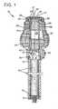
Fig. 1 is a cross-sectional side view of an embodiment of the sensor device of the present invention;- With reference to
Fig. 1 , an embodiment of theelongate sensor device 10 is shown that may be used for sensing nerve reactions of a patient by using a cold element, as explained below. The cooling element may hold a constant temperature of about - 5 to -15 C or any other suitable temperature range. Only a small cooling power is required and it is often sufficient to use one peltier element. However, even lower temperatures can be accomplished by applying two peltier elements on top of each other. - The
device 10 is useful for determining the area affected by, for example, anesthesia on the body of the patient. Thedevice 10 has anelongate housing 12 that may contain apower source 14, such as batteries, held in place by aremovable lid 16. Acoupling 17 is arranged in thelid 16 and thecoupling 17 is suitable for connecting a battery charger to the battery. A mid-portion 18 of thehousing 12 has aswitch 20 for turning on and off thedevice 10. Thehousing 12 may also have alight emission diode 22 that indicates whether thedevice 10 is turned on or not. Thedevice 10 also has an enlargedcooling segment 24 that terminates at a threadedouter end 26. Thesegment 24 may contain flanges or segments to maximize asurface area 28 of thesegment 24. Thesegment 24 may be made of an extruded aluminum or any other suitable material with a high heat-conductivity index. - The
segment 24 is hollow and contain a volume of a material orsubstance 27, e.g. cooling liquid or water that has a higher thermal capacity than the material insegment 24. In this way, more heat can be absorbed during a limited time with very limited temperature increase insegment 24, especially when the ambient temperature is high and the cooling effect in theflanges 28 is lower. This is an advantage when thedevice 10 is used intermittently and the ambient air temperature is high that may result in a lower cooling effect from theflanges 28. - A plastic nut or
holder 30 may be removably attached to a threadedend 26 of thesegment 24. Theholder 30 may be made of any material with a low heat-conductivity such as glass-fiber composites or plastics. Thenut 30 may have a slantedinner diameter 34 to hold acover plate 36 and apeltier element 38 against the threadedend 32. Theplate 36 may be used to protect theelement 38 from damage such as scratches, corrosion and wear during use and cleaning of thedevice 10. - The
peltier element 38 is electrically connected, viawires 39, to anelectrical circuit 40 that is turn is powered by thepower source 14. Theelement 38 may have a plurality of layers and when theelement 38 is electrically connected theelement 38 makes atop layer 41 substantially cooler than abottom layer 43. For example, thelayer 41 may have a temperature range of -5 to -15 C while theopposite bottom layer 43 may have a temperature of +30 to +50 C depending on the power applied to thepeltier element 38. In a way, theelement 38 is opposite to that of a conventional thermo-element. - One important function of the
solid segment 24 is to lead away the heat generated in thebottom layer 43 because anupper surface 45 of theend 26 of thesegment 24 is, preferably, in direct contact with thelayer 43. - Because the
segment 24 has alarge surface area 28 and is made of a material with high heat conductivity, thesegment 24 may efficiently lead away the heat generated by theelement 38 so as to increase the efficiency of theelement 38. By maintaining the temperature of thelayer 43 at about +35 C, it is possible to operate theelement 38 at half the full effect so that the temperature difference between the cool side and the warm side is about 35-45 degrees. When operated at a full power, the temperature difference between the cooledlayer 41 and theheated layer 43 may be as high as 78 C or higher. The use of thesegment 24 thus saves on the energy consumption of thedevice 10. - In operation, the user may turn on the
device 10 by switching on theswitch 20. The current runs through theelement 38 so that a substantial temperature difference is created between thelayer 41 and thelayer 43 and so that thelayer 41 becomes very cold. Since theelement 36 has a relatively high conductivity, anupper surface 47 of theelement 36 also becomes cold. Thesurface 47 is applied to the patient who has been treated with anesthesia to determine if the patient can feel thecold surface 47 that is applied directly on the skin of the patient. When the effect of the anesthesia has been determined, the medical professional may turn off thedevice 10 by switching theswitch 20 to the off mode. An automatic switch-off after a suitable time can be arranged in theswitch function 20 in order to save the batteries. - As indicated above, because the
segment 24 is solid and has alarge surface area 28 it may be used to cool off theheated layer 43 of theelement 38. The heat from thelayer 43 is led into thesegment 24 via thesurface 45. In this way, thesurface 41 may be maintained at a low temperature while keeping the temperature difference between thelayers device 10, the same. It is important that theholder 30 is made of a material with low heat conductivity so that no heat is transferred from thelayer 43 to the cooledlayer 41 and theprotective sheet 36. - While the present invention has been described in accordance with preferred compositions and embodiments, it is to be understood that certain substitutions and alterations may be made thereto without departing from the scope of the following claims.
Claims (4)
- Sensor device to determine whether an area of a patient's body, subject to anaesthetic treatment, for instance before conducting a surgery thereto, is affected or not by said treatment by determining whether or not the patient can feel an application of a cold surface applied to his/her skin or not, comprising a peltier element (38) held by a holder (30) threadedly attached to an outer end (26) of a housing (24), the peltier element, when connected to a power source, having a cooled testing surface (41) and a heated inner surface (43), the heated inner surface (43) being directed oppositely of the cooled testing surface (41), the holder (30) being made from a material with a low heat conductivity, lower than that of the housing (24), to avoid heat transfer between the cooled testing surface (41) and the heated inner surface (43); the housing having a cavity (25) defined therein, containing a material (27) having a thermal capacity higher than that of the housing (24) for storing heat from the inner heated surface (43).
- Sensor according to claim 1,characterised in that, it comprises a cover plate (36) held by the holder (30), thereby fixing the cover plate (36) against the peltier element (38).
- Sensor according to claim 1 or 2,characterised in that, the housing (24), is manufactured from a material having a high heat conductivity and comprises an area of flanges (28), in order to increase transfer of heat to another medium in contact therewith.
- Sensor according to anyone of the preceding claims,characterised in that the housing (24) is arranged to be in operative thermal contact with the cavity (25) and the material (27) therein, whereby during a limited time, heat can be absorbed therein, limiting the temperature increase in the housing (24) and/or its flanges (28).
Applications Claiming Priority (3)
| Application Number | Priority Date | Filing Date | Title |
|---|---|---|---|
| US31955002P | 2002-09-15 | 2002-09-15 | |
| US319550P | 2002-09-15 | ||
| PCT/SE2003/001403WO2004024000A1 (en) | 2002-09-15 | 2003-09-08 | Sensor for determining the effect of anaesthetic treatment by cooling the skin with the sensor |
Publications (2)
| Publication Number | Publication Date |
|---|---|
| EP1549216A1 EP1549216A1 (en) | 2005-07-06 |
| EP1549216B1true EP1549216B1 (en) | 2010-01-06 |
Family
ID=31993699
Family Applications (1)
| Application Number | Title | Priority Date | Filing Date |
|---|---|---|---|
| EP03795524AExpired - LifetimeEP1549216B1 (en) | 2002-09-15 | 2003-09-08 | Sensor for determining the effect of anaesthetic treatment by cooling the skin with the sensor |
Country Status (6)
| Country | Link |
|---|---|
| US (1) | US7798975B2 (en) |
| EP (1) | EP1549216B1 (en) |
| AT (1) | ATE454091T1 (en) |
| AU (1) | AU2003261045A1 (en) |
| DE (1) | DE60330879D1 (en) |
| WO (1) | WO2004024000A1 (en) |
Families Citing this family (6)
| Publication number | Priority date | Publication date | Assignee | Title |
|---|---|---|---|---|
| US10136977B2 (en) | 2008-11-03 | 2018-11-27 | Thomas L. Jones | Dental testing device for heat sensitivity |
| EP2269527A1 (en) | 2009-07-03 | 2011-01-05 | Levi Emmerik A. Dewaegenaere | System and method for controlling the operation of a therapeutic pad |
| EP2269544A1 (en)* | 2009-07-03 | 2011-01-05 | Levi Emmerik A. Dewaegenaere | Thermal treatment system and apparatus with biofeedback-driven protocol |
| CN104665773B (en)* | 2015-02-12 | 2017-07-14 | 南京大学医学院附属鼓楼医院 | Local anaesthesia scope analyzer |
| EP4450102A3 (en)* | 2015-03-26 | 2025-02-26 | The Regents Of The University Of Michigan | Applicator for cryoanesthesia and analgesia |
| CN110811631B (en)* | 2019-11-07 | 2022-07-12 | 重庆市江津区中心医院 | Pain measuring instrument device for anesthesia department |
Citations (1)
| Publication number | Priority date | Publication date | Assignee | Title |
|---|---|---|---|---|
| DE19752282A1 (en)* | 1997-11-26 | 1999-06-02 | Bembenek Peter Dr Med Dent | Diagnostics and therapy device |
Family Cites Families (14)
| Publication number | Priority date | Publication date | Assignee | Title |
|---|---|---|---|---|
| US4308013A (en)* | 1980-06-19 | 1981-12-29 | Emery Major | Thermoelectric diagnostic instrument |
| DE3821219C1 (en)* | 1988-06-23 | 1989-08-24 | Phywe Systeme Gmbh, 3400 Goettingen, De | |
| US5097828A (en)* | 1990-09-25 | 1992-03-24 | Richard Deutsch | Thermoelectric therapy device |
| GB9022623D0 (en)* | 1990-10-18 | 1990-11-28 | Univ Manchester | Depth of anaesthesia monitoring |
| US5191896A (en)* | 1991-06-28 | 1993-03-09 | Medoc Ltd. | Apparatus for measuring threshold sensitivity to a stimulus |
| RU2055329C1 (en)* | 1991-10-17 | 1996-02-27 | Московский научно-исследовательский институт педиатрии и детской хирургии | Method of evaluation of narcosis adequacy |
| US5830208A (en)* | 1997-01-31 | 1998-11-03 | Laserlite, Llc | Peltier cooled apparatus and methods for dermatological treatment |
| US6023932A (en)* | 1997-08-25 | 2000-02-15 | Johnston; Robert | Topical cooling device |
| US6196839B1 (en)* | 1999-01-29 | 2001-03-06 | Robert Gregg Ross | Continuous use orthodontic cooling appliance |
| US6356775B1 (en)* | 1999-04-20 | 2002-03-12 | Kyoho Machine Works. Ltd. | Biological data observation system |
| WO2001032114A1 (en)* | 1999-11-02 | 2001-05-10 | Wizcare Ltd. | Skin-gripper |
| JP2001190586A (en)* | 2000-01-11 | 2001-07-17 | Ohiro Seisakusho:Kk | Facial treatment implement |
| US6801803B2 (en)* | 2000-10-16 | 2004-10-05 | Instrumentarium Corp. | Method and apparatus for determining the cerebral state of a patient with fast response |
| US7037326B2 (en)* | 2003-03-14 | 2006-05-02 | Hee-Young Lee | Skin cooling device using thermoelectric element |
- 2003
- 2003-09-08EPEP03795524Apatent/EP1549216B1/ennot_activeExpired - Lifetime
- 2003-09-08DEDE60330879Tpatent/DE60330879D1/ennot_activeExpired - Lifetime
- 2003-09-08USUS10/527,080patent/US7798975B2/ennot_activeExpired - Fee Related
- 2003-09-08ATAT03795524Tpatent/ATE454091T1/ennot_activeIP Right Cessation
- 2003-09-08AUAU2003261045Apatent/AU2003261045A1/ennot_activeAbandoned
- 2003-09-08WOPCT/SE2003/001403patent/WO2004024000A1/ennot_activeApplication Discontinuation
Patent Citations (1)
| Publication number | Priority date | Publication date | Assignee | Title |
|---|---|---|---|---|
| DE19752282A1 (en)* | 1997-11-26 | 1999-06-02 | Bembenek Peter Dr Med Dent | Diagnostics and therapy device |
Also Published As
| Publication number | Publication date |
|---|---|
| US7798975B2 (en) | 2010-09-21 |
| WO2004024000A1 (en) | 2004-03-25 |
| EP1549216A1 (en) | 2005-07-06 |
| AU2003261045A1 (en) | 2004-04-30 |
| ATE454091T1 (en) | 2010-01-15 |
| US20060074339A1 (en) | 2006-04-06 |
| DE60330879D1 (en) | 2010-02-25 |
Similar Documents
| Publication | Publication Date | Title |
|---|---|---|
| ES2764776T3 (en) | Cooling devices with flexible sensors | |
| US20070193278A1 (en) | Cooling device and method | |
| EP3531990A1 (en) | Cooling device | |
| US20120065713A1 (en) | Thermo-electric device | |
| CN110013378A (en) | With multiple controllable cooling elements to provide the cooling device of predetermined cooling profile | |
| WO2019046129A1 (en) | Handheld thermal therapy device | |
| EP1549216B1 (en) | Sensor for determining the effect of anaesthetic treatment by cooling the skin with the sensor | |
| CN217548356U (en) | Temperature control cold and hot compress integrated compress device | |
| CN105640692A (en) | Intelligent temperature-control semiconductor cold-compress instrument | |
| JP4956758B2 (en) | Puncture pain relief device | |
| CN208339656U (en) | A kind of neck health care device | |
| CN111643261A (en) | Wiping type constant-temperature physical cooler | |
| US20240065882A1 (en) | Smart thermoelectric brain hypothermia thermohipotherm and brain thermography device | |
| WO1994009714A1 (en) | Electrically operated heating tool | |
| CN213822400U (en) | Cold and hot skin scraping beauty instrument | |
| WO1993016667A9 (en) | Cryogenic probe | |
| KR20140041105A (en) | Medical equipment with cool and warm sensing function | |
| WO1993016667A1 (en) | Cryogenic probe | |
| WO2017193616A1 (en) | Wearable physical cooling device for head | |
| CN217744763U (en) | Carbon dioxide laser post-cold compress treatment device | |
| CN221556275U (en) | Medical ice cap | |
| KR101477347B1 (en) | Medical equipment system with cool and warm sensing function | |
| RU4472U1 (en) | DEVICE FOR EXPOSING COLD TO A BIOLOGICALLY ACTIVE POINT | |
| US10045808B2 (en) | Device for effecting change in tissue at a treatment site | |
| KR101375134B1 (en) | Poultice eye patch |
Legal Events
| Date | Code | Title | Description |
|---|---|---|---|
| PUAI | Public reference made under article 153(3) epc to a published international application that has entered the european phase | Free format text:ORIGINAL CODE: 0009012 | |
| 17P | Request for examination filed | Effective date:20050415 | |
| AK | Designated contracting states | Kind code of ref document:A1 Designated state(s):AT BE BG CH CY CZ DE DK EE ES FI FR GB GR HU IE IT LI LU MC NL PT RO SE SI SK TR | |
| AX | Request for extension of the european patent | Extension state:AL LT LV MK | |
| DAX | Request for extension of the european patent (deleted) | ||
| RIC1 | Information provided on ipc code assigned before grant | Ipc:H01L 35/28 20060101ALI20070206BHEP Ipc:H01L 23/38 20060101ALI20070206BHEP Ipc:A61B 5/11 20060101ALI20070206BHEP Ipc:A61B 5/16 20060101AFI20070206BHEP | |
| 17Q | First examination report despatched | Effective date:20070807 | |
| GRAP | Despatch of communication of intention to grant a patent | Free format text:ORIGINAL CODE: EPIDOSNIGR1 | |
| RAP1 | Party data changed (applicant data changed or rights of an application transferred) | Owner name:ADOLFSSON, RUNE | |
| RIN1 | Information on inventor provided before grant (corrected) | Inventor name:ADOLFSSON, RUNE | |
| GRAS | Grant fee paid | Free format text:ORIGINAL CODE: EPIDOSNIGR3 | |
| GRAA | (expected) grant | Free format text:ORIGINAL CODE: 0009210 | |
| RIN1 | Information on inventor provided before grant (corrected) | Inventor name:ELIASSON, LENNART Inventor name:ADOLFSON, RUNE | |
| AK | Designated contracting states | Kind code of ref document:B1 Designated state(s):AT BE BG CH CY CZ DE DK EE ES FI FR GB GR HU IE IT LI LU MC NL PT RO SE SI SK TR | |
| REG | Reference to a national code | Ref country code:GB Ref legal event code:FG4D | |
| REG | Reference to a national code | Ref country code:CH Ref legal event code:EP | |
| REG | Reference to a national code | Ref country code:IE Ref legal event code:FG4D | |
| REF | Corresponds to: | Ref document number:60330879 Country of ref document:DE Date of ref document:20100225 Kind code of ref document:P | |
| REG | Reference to a national code | Ref country code:NL Ref legal event code:VDEP Effective date:20100106 | |
| PG25 | Lapsed in a contracting state [announced via postgrant information from national office to epo] | Ref country code:SI Free format text:LAPSE BECAUSE OF FAILURE TO SUBMIT A TRANSLATION OF THE DESCRIPTION OR TO PAY THE FEE WITHIN THE PRESCRIBED TIME-LIMIT Effective date:20100106 | |
| PG25 | Lapsed in a contracting state [announced via postgrant information from national office to epo] | Ref country code:AT Free format text:LAPSE BECAUSE OF FAILURE TO SUBMIT A TRANSLATION OF THE DESCRIPTION OR TO PAY THE FEE WITHIN THE PRESCRIBED TIME-LIMIT Effective date:20100106 | |
| PG25 | Lapsed in a contracting state [announced via postgrant information from national office to epo] | Ref country code:ES Free format text:LAPSE BECAUSE OF FAILURE TO SUBMIT A TRANSLATION OF THE DESCRIPTION OR TO PAY THE FEE WITHIN THE PRESCRIBED TIME-LIMIT Effective date:20100417 Ref country code:NL Free format text:LAPSE BECAUSE OF FAILURE TO SUBMIT A TRANSLATION OF THE DESCRIPTION OR TO PAY THE FEE WITHIN THE PRESCRIBED TIME-LIMIT Effective date:20100106 Ref country code:PT Free format text:LAPSE BECAUSE OF FAILURE TO SUBMIT A TRANSLATION OF THE DESCRIPTION OR TO PAY THE FEE WITHIN THE PRESCRIBED TIME-LIMIT Effective date:20100506 | |
| PG25 | Lapsed in a contracting state [announced via postgrant information from national office to epo] | Ref country code:FI Free format text:LAPSE BECAUSE OF FAILURE TO SUBMIT A TRANSLATION OF THE DESCRIPTION OR TO PAY THE FEE WITHIN THE PRESCRIBED TIME-LIMIT Effective date:20100106 | |
| PG25 | Lapsed in a contracting state [announced via postgrant information from national office to epo] | Ref country code:GR Free format text:LAPSE BECAUSE OF FAILURE TO SUBMIT A TRANSLATION OF THE DESCRIPTION OR TO PAY THE FEE WITHIN THE PRESCRIBED TIME-LIMIT Effective date:20100407 Ref country code:EE Free format text:LAPSE BECAUSE OF FAILURE TO SUBMIT A TRANSLATION OF THE DESCRIPTION OR TO PAY THE FEE WITHIN THE PRESCRIBED TIME-LIMIT Effective date:20100106 Ref country code:CY Free format text:LAPSE BECAUSE OF FAILURE TO SUBMIT A TRANSLATION OF THE DESCRIPTION OR TO PAY THE FEE WITHIN THE PRESCRIBED TIME-LIMIT Effective date:20100106 Ref country code:BE Free format text:LAPSE BECAUSE OF FAILURE TO SUBMIT A TRANSLATION OF THE DESCRIPTION OR TO PAY THE FEE WITHIN THE PRESCRIBED TIME-LIMIT Effective date:20100106 Ref country code:SE Free format text:LAPSE BECAUSE OF FAILURE TO SUBMIT A TRANSLATION OF THE DESCRIPTION OR TO PAY THE FEE WITHIN THE PRESCRIBED TIME-LIMIT Effective date:20100106 Ref country code:RO Free format text:LAPSE BECAUSE OF FAILURE TO SUBMIT A TRANSLATION OF THE DESCRIPTION OR TO PAY THE FEE WITHIN THE PRESCRIBED TIME-LIMIT Effective date:20100106 | |
| PLBE | No opposition filed within time limit | Free format text:ORIGINAL CODE: 0009261 | |
| STAA | Information on the status of an ep patent application or granted ep patent | Free format text:STATUS: NO OPPOSITION FILED WITHIN TIME LIMIT | |
| PG25 | Lapsed in a contracting state [announced via postgrant information from national office to epo] | Ref country code:SK Free format text:LAPSE BECAUSE OF FAILURE TO SUBMIT A TRANSLATION OF THE DESCRIPTION OR TO PAY THE FEE WITHIN THE PRESCRIBED TIME-LIMIT Effective date:20100106 Ref country code:CZ Free format text:LAPSE BECAUSE OF FAILURE TO SUBMIT A TRANSLATION OF THE DESCRIPTION OR TO PAY THE FEE WITHIN THE PRESCRIBED TIME-LIMIT Effective date:20100106 Ref country code:BG Free format text:LAPSE BECAUSE OF FAILURE TO SUBMIT A TRANSLATION OF THE DESCRIPTION OR TO PAY THE FEE WITHIN THE PRESCRIBED TIME-LIMIT Effective date:20100406 | |
| 26N | No opposition filed | Effective date:20101007 | |
| PG25 | Lapsed in a contracting state [announced via postgrant information from national office to epo] | Ref country code:DK Free format text:LAPSE BECAUSE OF FAILURE TO SUBMIT A TRANSLATION OF THE DESCRIPTION OR TO PAY THE FEE WITHIN THE PRESCRIBED TIME-LIMIT Effective date:20100106 | |
| PG25 | Lapsed in a contracting state [announced via postgrant information from national office to epo] | Ref country code:IT Free format text:LAPSE BECAUSE OF FAILURE TO SUBMIT A TRANSLATION OF THE DESCRIPTION OR TO PAY THE FEE WITHIN THE PRESCRIBED TIME-LIMIT Effective date:20100106 | |
| PG25 | Lapsed in a contracting state [announced via postgrant information from national office to epo] | Ref country code:MC Free format text:LAPSE BECAUSE OF NON-PAYMENT OF DUE FEES Effective date:20100930 | |
| REG | Reference to a national code | Ref country code:CH Ref legal event code:PL | |
| PG25 | Lapsed in a contracting state [announced via postgrant information from national office to epo] | Ref country code:IE Free format text:LAPSE BECAUSE OF NON-PAYMENT OF DUE FEES Effective date:20100908 Ref country code:LI Free format text:LAPSE BECAUSE OF NON-PAYMENT OF DUE FEES Effective date:20100930 Ref country code:CH Free format text:LAPSE BECAUSE OF NON-PAYMENT OF DUE FEES Effective date:20100930 | |
| PG25 | Lapsed in a contracting state [announced via postgrant information from national office to epo] | Ref country code:HU Free format text:LAPSE BECAUSE OF FAILURE TO SUBMIT A TRANSLATION OF THE DESCRIPTION OR TO PAY THE FEE WITHIN THE PRESCRIBED TIME-LIMIT Effective date:20100707 Ref country code:LU Free format text:LAPSE BECAUSE OF NON-PAYMENT OF DUE FEES Effective date:20100908 | |
| PG25 | Lapsed in a contracting state [announced via postgrant information from national office to epo] | Ref country code:TR Free format text:LAPSE BECAUSE OF FAILURE TO SUBMIT A TRANSLATION OF THE DESCRIPTION OR TO PAY THE FEE WITHIN THE PRESCRIBED TIME-LIMIT Effective date:20100106 | |
| REG | Reference to a national code | Ref country code:FR Ref legal event code:PLFP Year of fee payment:13 | |
| PGFP | Annual fee paid to national office [announced via postgrant information from national office to epo] | Ref country code:GB Payment date:20150917 Year of fee payment:13 Ref country code:DE Payment date:20150922 Year of fee payment:13 | |
| PGFP | Annual fee paid to national office [announced via postgrant information from national office to epo] | Ref country code:FR Payment date:20150922 Year of fee payment:13 | |
| REG | Reference to a national code | Ref country code:DE Ref legal event code:R119 Ref document number:60330879 Country of ref document:DE | |
| GBPC | Gb: european patent ceased through non-payment of renewal fee | Effective date:20160908 | |
| REG | Reference to a national code | Ref country code:FR Ref legal event code:ST Effective date:20170531 | |
| PG25 | Lapsed in a contracting state [announced via postgrant information from national office to epo] | Ref country code:DE Free format text:LAPSE BECAUSE OF NON-PAYMENT OF DUE FEES Effective date:20170401 Ref country code:GB Free format text:LAPSE BECAUSE OF NON-PAYMENT OF DUE FEES Effective date:20160908 Ref country code:FR Free format text:LAPSE BECAUSE OF NON-PAYMENT OF DUE FEES Effective date:20160930 |