EP1547533A2 - Minimally invasive revascularization apparatus. - Google Patents
Minimally invasive revascularization apparatus.Download PDFInfo
- Publication number
- EP1547533A2 EP1547533A2EP05002803AEP05002803AEP1547533A2EP 1547533 A2EP1547533 A2EP 1547533A2EP 05002803 AEP05002803 AEP 05002803AEP 05002803 AEP05002803 AEP 05002803AEP 1547533 A2EP1547533 A2EP 1547533A2
- Authority
- EP
- European Patent Office
- Prior art keywords
- conduit
- apparatus defined
- connector
- longitudinal
- lumen
- Prior art date
- Legal status (The legal status is an assumption and is not a legal conclusion. Google has not performed a legal analysis and makes no representation as to the accuracy of the status listed.)
- Withdrawn
Links
Images


Classifications
- A—HUMAN NECESSITIES
- A61—MEDICAL OR VETERINARY SCIENCE; HYGIENE
- A61F—FILTERS IMPLANTABLE INTO BLOOD VESSELS; PROSTHESES; DEVICES PROVIDING PATENCY TO, OR PREVENTING COLLAPSING OF, TUBULAR STRUCTURES OF THE BODY, e.g. STENTS; ORTHOPAEDIC, NURSING OR CONTRACEPTIVE DEVICES; FOMENTATION; TREATMENT OR PROTECTION OF EYES OR EARS; BANDAGES, DRESSINGS OR ABSORBENT PADS; FIRST-AID KITS
- A61F2/00—Filters implantable into blood vessels; Prostheses, i.e. artificial substitutes or replacements for parts of the body; Appliances for connecting them with the body; Devices providing patency to, or preventing collapsing of, tubular structures of the body, e.g. stents
- A61F2/02—Prostheses implantable into the body
- A61F2/04—Hollow or tubular parts of organs, e.g. bladders, tracheae, bronchi or bile ducts
- A61F2/06—Blood vessels
- A61F2/064—Blood vessels with special features to facilitate anastomotic coupling
- A—HUMAN NECESSITIES
- A61—MEDICAL OR VETERINARY SCIENCE; HYGIENE
- A61B—DIAGNOSIS; SURGERY; IDENTIFICATION
- A61B17/00—Surgical instruments, devices or methods
- A61B17/064—Surgical staples, i.e. penetrating the tissue
- A61B17/0644—Surgical staples, i.e. penetrating the tissue penetrating the tissue, deformable to closed position
- A—HUMAN NECESSITIES
- A61—MEDICAL OR VETERINARY SCIENCE; HYGIENE
- A61B—DIAGNOSIS; SURGERY; IDENTIFICATION
- A61B17/00—Surgical instruments, devices or methods
- A61B17/11—Surgical instruments, devices or methods for performing anastomosis; Buttons for anastomosis
- A—HUMAN NECESSITIES
- A61—MEDICAL OR VETERINARY SCIENCE; HYGIENE
- A61B—DIAGNOSIS; SURGERY; IDENTIFICATION
- A61B17/00—Surgical instruments, devices or methods
- A61B17/32—Surgical cutting instruments
- A61B17/3205—Excision instruments
- A61B17/3207—Atherectomy devices working by cutting or abrading; Similar devices specially adapted for non-vascular obstructions
- A—HUMAN NECESSITIES
- A61—MEDICAL OR VETERINARY SCIENCE; HYGIENE
- A61M—DEVICES FOR INTRODUCING MEDIA INTO, OR ONTO, THE BODY; DEVICES FOR TRANSDUCING BODY MEDIA OR FOR TAKING MEDIA FROM THE BODY; DEVICES FOR PRODUCING OR ENDING SLEEP OR STUPOR
- A61M25/00—Catheters; Hollow probes
- A61M25/0067—Catheters; Hollow probes characterised by the distal end, e.g. tips
- A61M25/0074—Dynamic characteristics of the catheter tip, e.g. openable, closable, expandable or deformable
- A—HUMAN NECESSITIES
- A61—MEDICAL OR VETERINARY SCIENCE; HYGIENE
- A61M—DEVICES FOR INTRODUCING MEDIA INTO, OR ONTO, THE BODY; DEVICES FOR TRANSDUCING BODY MEDIA OR FOR TAKING MEDIA FROM THE BODY; DEVICES FOR PRODUCING OR ENDING SLEEP OR STUPOR
- A61M25/00—Catheters; Hollow probes
- A61M25/10—Balloon catheters
- A—HUMAN NECESSITIES
- A61—MEDICAL OR VETERINARY SCIENCE; HYGIENE
- A61B—DIAGNOSIS; SURGERY; IDENTIFICATION
- A61B17/00—Surgical instruments, devices or methods
- A61B17/12—Surgical instruments, devices or methods for ligaturing or otherwise compressing tubular parts of the body, e.g. blood vessels or umbilical cord
- A61B17/122—Clamps or clips, e.g. for the umbilical cord
- A—HUMAN NECESSITIES
- A61—MEDICAL OR VETERINARY SCIENCE; HYGIENE
- A61B—DIAGNOSIS; SURGERY; IDENTIFICATION
- A61B17/00—Surgical instruments, devices or methods
- A61B17/22—Implements for squeezing-off ulcers or the like on inner organs of the body; Implements for scraping-out cavities of body organs, e.g. bones; for invasive removal or destruction of calculus using mechanical vibrations; for removing obstructions in blood vessels, not otherwise provided for
- A61B17/221—Gripping devices in the form of loops or baskets for gripping calculi or similar types of obstructions
- A—HUMAN NECESSITIES
- A61—MEDICAL OR VETERINARY SCIENCE; HYGIENE
- A61B—DIAGNOSIS; SURGERY; IDENTIFICATION
- A61B17/00—Surgical instruments, devices or methods
- A61B17/32—Surgical cutting instruments
- A61B17/3205—Excision instruments
- A61B17/32053—Punch like cutting instruments, e.g. using a cylindrical or oval knife
- A—HUMAN NECESSITIES
- A61—MEDICAL OR VETERINARY SCIENCE; HYGIENE
- A61B—DIAGNOSIS; SURGERY; IDENTIFICATION
- A61B17/00—Surgical instruments, devices or methods
- A61B17/34—Trocars; Puncturing needles
- A61B17/3478—Endoscopic needles, e.g. for infusion
- A—HUMAN NECESSITIES
- A61—MEDICAL OR VETERINARY SCIENCE; HYGIENE
- A61B—DIAGNOSIS; SURGERY; IDENTIFICATION
- A61B17/00—Surgical instruments, devices or methods
- A61B17/00234—Surgical instruments, devices or methods for minimally invasive surgery
- A61B2017/00238—Type of minimally invasive operation
- A61B2017/00243—Type of minimally invasive operation cardiac
- A61B2017/00247—Making holes in the wall of the heart, e.g. laser Myocardial revascularization
- A61B2017/00252—Making holes in the wall of the heart, e.g. laser Myocardial revascularization for by-pass connections, i.e. connections from heart chamber to blood vessel or from blood vessel to blood vessel
- A—HUMAN NECESSITIES
- A61—MEDICAL OR VETERINARY SCIENCE; HYGIENE
- A61B—DIAGNOSIS; SURGERY; IDENTIFICATION
- A61B17/00—Surgical instruments, devices or methods
- A61B17/11—Surgical instruments, devices or methods for performing anastomosis; Buttons for anastomosis
- A61B2017/1107—Surgical instruments, devices or methods for performing anastomosis; Buttons for anastomosis for blood vessels
- A—HUMAN NECESSITIES
- A61—MEDICAL OR VETERINARY SCIENCE; HYGIENE
- A61B—DIAGNOSIS; SURGERY; IDENTIFICATION
- A61B17/00—Surgical instruments, devices or methods
- A61B17/11—Surgical instruments, devices or methods for performing anastomosis; Buttons for anastomosis
- A61B2017/1135—End-to-side connections, e.g. T- or Y-connections
- A—HUMAN NECESSITIES
- A61—MEDICAL OR VETERINARY SCIENCE; HYGIENE
- A61B—DIAGNOSIS; SURGERY; IDENTIFICATION
- A61B17/00—Surgical instruments, devices or methods
- A61B17/22—Implements for squeezing-off ulcers or the like on inner organs of the body; Implements for scraping-out cavities of body organs, e.g. bones; for invasive removal or destruction of calculus using mechanical vibrations; for removing obstructions in blood vessels, not otherwise provided for
- A61B2017/22038—Implements for squeezing-off ulcers or the like on inner organs of the body; Implements for scraping-out cavities of body organs, e.g. bones; for invasive removal or destruction of calculus using mechanical vibrations; for removing obstructions in blood vessels, not otherwise provided for with a guide wire
- A—HUMAN NECESSITIES
- A61—MEDICAL OR VETERINARY SCIENCE; HYGIENE
- A61B—DIAGNOSIS; SURGERY; IDENTIFICATION
- A61B17/00—Surgical instruments, devices or methods
- A61B17/22—Implements for squeezing-off ulcers or the like on inner organs of the body; Implements for scraping-out cavities of body organs, e.g. bones; for invasive removal or destruction of calculus using mechanical vibrations; for removing obstructions in blood vessels, not otherwise provided for
- A61B2017/22072—Implements for squeezing-off ulcers or the like on inner organs of the body; Implements for scraping-out cavities of body organs, e.g. bones; for invasive removal or destruction of calculus using mechanical vibrations; for removing obstructions in blood vessels, not otherwise provided for with an instrument channel, e.g. for replacing one instrument by the other
- A61B2017/22074—Implements for squeezing-off ulcers or the like on inner organs of the body; Implements for scraping-out cavities of body organs, e.g. bones; for invasive removal or destruction of calculus using mechanical vibrations; for removing obstructions in blood vessels, not otherwise provided for with an instrument channel, e.g. for replacing one instrument by the other the instrument being only slidable in a channel, e.g. advancing optical fibre through a channel
- A61B2017/22077—Implements for squeezing-off ulcers or the like on inner organs of the body; Implements for scraping-out cavities of body organs, e.g. bones; for invasive removal or destruction of calculus using mechanical vibrations; for removing obstructions in blood vessels, not otherwise provided for with an instrument channel, e.g. for replacing one instrument by the other the instrument being only slidable in a channel, e.g. advancing optical fibre through a channel with a part piercing the tissue
- A—HUMAN NECESSITIES
- A61—MEDICAL OR VETERINARY SCIENCE; HYGIENE
- A61B—DIAGNOSIS; SURGERY; IDENTIFICATION
- A61B17/00—Surgical instruments, devices or methods
- A61B17/22—Implements for squeezing-off ulcers or the like on inner organs of the body; Implements for scraping-out cavities of body organs, e.g. bones; for invasive removal or destruction of calculus using mechanical vibrations; for removing obstructions in blood vessels, not otherwise provided for
- A61B17/221—Gripping devices in the form of loops or baskets for gripping calculi or similar types of obstructions
- A61B2017/2212—Gripping devices in the form of loops or baskets for gripping calculi or similar types of obstructions having a closed distal end, e.g. a loop
- A—HUMAN NECESSITIES
- A61—MEDICAL OR VETERINARY SCIENCE; HYGIENE
- A61B—DIAGNOSIS; SURGERY; IDENTIFICATION
- A61B17/00—Surgical instruments, devices or methods
- A61B17/22—Implements for squeezing-off ulcers or the like on inner organs of the body; Implements for scraping-out cavities of body organs, e.g. bones; for invasive removal or destruction of calculus using mechanical vibrations; for removing obstructions in blood vessels, not otherwise provided for
- A61B17/221—Gripping devices in the form of loops or baskets for gripping calculi or similar types of obstructions
- A61B2017/2217—Gripping devices in the form of loops or baskets for gripping calculi or similar types of obstructions single wire changing shape to a gripping configuration
- A—HUMAN NECESSITIES
- A61—MEDICAL OR VETERINARY SCIENCE; HYGIENE
- A61B—DIAGNOSIS; SURGERY; IDENTIFICATION
- A61B90/00—Instruments, implements or accessories specially adapted for surgery or diagnosis and not covered by any of the groups A61B1/00 - A61B50/00, e.g. for luxation treatment or for protecting wound edges
- A61B90/39—Markers, e.g. radio-opaque or breast lesions markers
- A—HUMAN NECESSITIES
- A61—MEDICAL OR VETERINARY SCIENCE; HYGIENE
- A61M—DEVICES FOR INTRODUCING MEDIA INTO, OR ONTO, THE BODY; DEVICES FOR TRANSDUCING BODY MEDIA OR FOR TAKING MEDIA FROM THE BODY; DEVICES FOR PRODUCING OR ENDING SLEEP OR STUPOR
- A61M25/00—Catheters; Hollow probes
- A61M25/0067—Catheters; Hollow probes characterised by the distal end, e.g. tips
- A61M25/008—Strength or flexibility characteristics of the catheter tip
- A61M2025/0081—Soft tip
- A—HUMAN NECESSITIES
- A61—MEDICAL OR VETERINARY SCIENCE; HYGIENE
- A61M—DEVICES FOR INTRODUCING MEDIA INTO, OR ONTO, THE BODY; DEVICES FOR TRANSDUCING BODY MEDIA OR FOR TAKING MEDIA FROM THE BODY; DEVICES FOR PRODUCING OR ENDING SLEEP OR STUPOR
- A61M25/00—Catheters; Hollow probes
- A61M25/10—Balloon catheters
- A61M2025/1043—Balloon catheters with special features or adapted for special applications
- A61M2025/1079—Balloon catheters with special features or adapted for special applications having radio-opaque markers in the region of the balloon
- A—HUMAN NECESSITIES
- A61—MEDICAL OR VETERINARY SCIENCE; HYGIENE
- A61M—DEVICES FOR INTRODUCING MEDIA INTO, OR ONTO, THE BODY; DEVICES FOR TRANSDUCING BODY MEDIA OR FOR TAKING MEDIA FROM THE BODY; DEVICES FOR PRODUCING OR ENDING SLEEP OR STUPOR
- A61M25/00—Catheters; Hollow probes
- A61M25/0067—Catheters; Hollow probes characterised by the distal end, e.g. tips
- A61M25/0068—Static characteristics of the catheter tip, e.g. shape, atraumatic tip, curved tip or tip structure
- A—HUMAN NECESSITIES
- A61—MEDICAL OR VETERINARY SCIENCE; HYGIENE
- A61M—DEVICES FOR INTRODUCING MEDIA INTO, OR ONTO, THE BODY; DEVICES FOR TRANSDUCING BODY MEDIA OR FOR TAKING MEDIA FROM THE BODY; DEVICES FOR PRODUCING OR ENDING SLEEP OR STUPOR
- A61M25/00—Catheters; Hollow probes
- A61M25/0067—Catheters; Hollow probes characterised by the distal end, e.g. tips
- A61M25/0082—Catheter tip comprising a tool
- A—HUMAN NECESSITIES
- A61—MEDICAL OR VETERINARY SCIENCE; HYGIENE
- A61M—DEVICES FOR INTRODUCING MEDIA INTO, OR ONTO, THE BODY; DEVICES FOR TRANSDUCING BODY MEDIA OR FOR TAKING MEDIA FROM THE BODY; DEVICES FOR PRODUCING OR ENDING SLEEP OR STUPOR
- A61M25/00—Catheters; Hollow probes
- A61M25/01—Introducing, guiding, advancing, emplacing or holding catheters
- A61M25/0105—Steering means as part of the catheter or advancing means; Markers for positioning
- A61M25/0108—Steering means as part of the catheter or advancing means; Markers for positioning using radio-opaque or ultrasound markers
Definitions
- This inventionrelates to medical apparatus and methods, and more particularly to apparatus and methods for installing a tubular graft in a patient for such purposes as bypassing an occlusion in the patient's tubular body conduit structure.
- Goldsteen et al.U.S. patent 5,976,178, which is hereby incorporated by reference herein in its entirety, shows, among other things, apparatus and methods for installing a graft conduit in a patient, with most or all of the work being done intraluminally through the patient's existing body conduit structure. Testing and further development work have suggested that it would be advantageous to improve and/or augment some aspects of apparatus and/or methods of the kind shown in the above-mentioned Goldsteen et al. reference.
- a guide structurein a patient between two locations along the patient's circulatory system that are to be connected by a bypass graft.
- the guide structureextends between those two locations outside the circulatory system (albeit within the patient) and is used to guide the bypass graft into place between those two locations.
- the guide structureis preferably installed in the patient intraluminally (i.e., via lumens of the patient's circulatory system), although there is a portion of the guide structure which ultimately extends outside the circulatory system as mentioned above.
- a portion of the guide structuremay be re-routable in the circulatory system to improve the alignment of the guide structure for purposes of optimal guidance of the bypass graft into place.
- the guide structuremay be re-routed so that, whereas both ends of the guide structure initially extend out of the patient, only one end of the re-routed guide structure extends out of the patient, while the other end of the guide structure dead-ends in the patient.
- the new routing of the guide structuremay improve its ability to guide the bypass graft into a desired alignment in the patient.
- the graft delivery structuremay include a very gradually tapered distal nose portion to facilitate entry of the apparatus into the patient's circulatory system at one end of the graft installation site.
- Improved connectors for attaching one or both ends of the graft conduit to the patient's circulatory systemmay also be used.
- an early stage in an illustrative coronary artery bypass procedure in accordance with the inventionincludes introducing a longitudinal guide member 100 (typically a guide wire, and therefore sometimes referred to as such herein) into the patient's circulatory system across the coronary artery occlusion 22 to be bypassed.
- guide wire 100may be introduced into the patient via a femoral (leg) artery (not shown). From the femoral artery, guide wire 100 may be pushed intraluminally into the patient's aorta 30, and from the aorta into the coronary artery 20 that has occlusion 22. Advancement of guide wire 100 may be stopped at any desired point after the distal portion of the guide wire has passed through occlusion 22.
- a catheter or catheter-like structure 200is introduced into the patient along guide wire 100 as shown in FIG. 2.
- FIG. 3A more detailed view of a distal portion of catheter 200 is shown in FIG. 3, wherein it can be seen that the catheter has an axially extending lumen 210 for containing guide wire 100 as the catheter is advanced along the guide wire.
- Guide wire 100facilitates passage of the distal portion of catheter 200 through occlusion 22 as shown in FIG. 2.
- guide wire 100is pulled proximally out of the catheter and out of the patient.
- a medial portion 220 of catheter 200is preferably constructed to form a laterally extending arch as shown in FIGS. 4 and 5 when guide wire 100 is withdrawn from the catheter.
- catheter 200may be made so that it resiliently tends to form an arch of a predetermined lateral extent when it is freed from the straightening effect of guide wire 100.
- the arch height Hmay be specifically designed to complement various artery sizes (e.g., 3.0 mm, 3.5 mm, 4.0 mm, etc., diameter vessels).
- the arch heightmay be selected to be approximately the same as or slightly greater than the inside diameter of the artery 20 into which the catheter will be inserted.
- the lumen 210 in catheter 200has a side branch 210a which exits from the side wall of the catheter at or near the apex of the above-described arch in the catheter.
- Catheter portion 220which forms the above-described arch, is preferably loaded with conventional radio-opaque filler (e.g., as indicated by the small plus signs in FIG. 17) to help the physician using the apparatus to radiologically locate and properly orient catheter portion 220 in the patient's artery.
- Portions of catheter 200 which are distal and proximal of portion 220may be less radio-opaque to help highlight portion 220.
- the objectiveis to position lumen branch 210a at the approximate location along artery 20 at which it is desired to connect one end of a bypass graft to the artery.
- Radiologic observationmay be further aided by providing a radiologically viewable (e.g., radio-opaque) marker band around the exit from lumen branch 210a (e.g., as shown at 224 in FIG. 17).
- a radiologically viewable marker bandaround the exit from lumen branch 210a (e.g., as shown at 224 in FIG. 17).
- radiologically viewablee.g., radio-opaque
- catheter 200preferably has an inner liner 230 of polytetrafluoroethylene to minimize internal friction.
- a reinforcing layersuch as a braid of wires 250 may be included to enable the catheter to transmit torque and to provide kink resistance.
- Polymer layer 240e.g., Pebax or nylon
- Internal lumen 210preferably extends along the entire length of the catheter and is used to allow the catheter to track over guide wire 100 as described above, and to subsequently guide a longitudinal piercing structure to the point on the wall of artery 20 where it is desired to connect one end of a bypass graft.
- the distal tip portion of catheter 200may be made especially soft and/or the external surface of the catheter may be coated with polytetrafluoroethylene to enhance the ability of the catheter to pass through an occlusion like occlusion 22.
- a soft tipalso helps make catheter 200 atraumatic.
- the distal tip portion of the cathetermay be tapered in the distal direction for similar reasons.
- the transverse dimensions of catheter 200are preferably made small (e.g., less than 3 French or 1.0 mm) to facilitate introduction of the catheter into the patient, especially a relatively small coronary artery and the even smaller passageway through the occlusion 22 in that artery.
- Arched section 220is made stiff enough to provide backup support for piercing the coronary artery wall as described below, as well as stability of the catheter in the coronary artery.
- Proximal sections of catheter 200are constructed to provide appropriate pushability and trackability of the catheter along guide wire 100. For example, catheter 200 may have differing flexibility at different locations along its length.
- a distal portion 220' of the cathetermay be configured to deflect or curve to the side when guide wire 100 is withdrawn as shown in FIG. 5a.
- Catheter 200 in FIG. 5ais positioned in coronary artery 20 so that after portion 220' curves to the side, the distal end of lumen 210 points to a location on the inside of the side wall of the artery similar to the location of the apex of the arch 220 in FIG.
- lumen 210does not need a separate, additional side exit 210a for the piercing structure because the distal end of lumen 210 can be used as the exit for the piercing structure.
- embodiments of the type shown in FIG. 5acan be constructed and operated similarly to embodiments of the type shown in FIG. 5 and described above.
- portion 220'is preferably such that after deflection one side of catheter 200 bears on the inside of one side of the coronary artery side wall at location 20d in order to maintain the distal end of the catheter close to or in contact with the other side of the coronary artery side wall at axially spaced location 20e. Further depiction and explanation of the invention will be made with reference to embodiments of the FIG. 5 type, but it will be understood that embodiments of the FIG. 5a type can be used instead if desired.
- a further step in accordance with the inventionrelates to accessing the aortic end of the desired bypass around occlusion 22.
- Another catheter or catheter-like structure 300is introduced intraluminally into the aorta as shown in FIG. 7.
- catheter 300is preferably introduced into the patient at a location remote from the coronary area.
- catheter 300may be introduced into the patient via a femoral artery.
- the distal portions of catheter 300are preferably remotely controlled from proximal portions of the apparatus which remain outside the patient at all times.
- catheter 300preferably includes pilot wire 310 disposed substantially concentrically inside hollow tubular needle catheter 320.
- Needle catheter 320is disposed substantially concentrically inside hollow tubular cutter catheter 330, which in turn is disposed substantially concentrically inside hollow tubular aortic access catheter 340.
- Catheter 300is pushed into the patient until its distal portion is adjacent the inside surface of the wall of the aorta where it is desired to connect the aortic end of the bypass graft around occlusion 22 (see FIGS. 7 and 8).
- Needle catheter 320is then pushed distally so that its sharpened distal end portion passes through the wall of aorta 30 as shown in FIG. 9.
- needle catheter 320preferably does not reach the pericardial membrane 40.
- the distal portion of needle catheter 320may be barbed as shown at 322 in FIG. 9a to help prevent the needle catheter from being inadvertently pulled back through the wall of aorta 30 and for other purposes that will be mentioned below.
- the next stepis to push the distal portion of pilot wire 310 out of the distal end of needle catheter 320 and into the space between aorta 30 and pericardial membrane 40 as shown in FIG. 10.
- Wire 310is preferably too flexible where not supported by needle catheter 320 to pierce pericardial membrane 40. A quantity of wire 310 therefore deposits itself in the space between aorta 30 and membrane 40 as shown in FIG. 10.
- the next stepis to push cutter catheter 330 in the distal direction so that a sharpened distal end of catheter 330 makes an annular cut through the wall of aorta 30 as shown in FIG. 11.
- barbs 322 on needle catheter 320help hold the toroidal "doughnut" 30a of aorta wall tissue that is cut away by cutter catheter 330 on the distal portion of catheter 320.
- Cutter catheter 330may be rotated about its central longitudinal axis to help it cut through the aorta wall tissue. After passing through the aorta wall as shown in FIG. 11, the distal portion of cutter catheter 330 tends to follow pilot wire 310 in the space between aorta 30 and pericardial membrane 40.
- cutter catheter 330This helps prevent cutter catheter 330 from inadvertently cutting through membrane 40.
- a typical diameter for cutter catheter 330is approximately 3mm.
- the cutter catheter shaftfunctions as a plug through the aperture in the aorta wall that the cutter catheter has formed. This prevents blood flow from the aorta into the pericardial space.
- aortic access catheter 340uses the shaft of cutter catheter 330 as a guide. Assuming that the diameter of the cutter catheter is approximately 3mm, the diameter of aortic access catheter 340 may be approximately 5mm. The resulting expansion of the aortic opening from 3mm to 5mm makes use of the elastic recoil of the aorta to help seal the aortic opening around catheter 340, thereby ensuring no blood leakage into the pericardial space while catheter 340 is positioned through the aorta wall.
- catheter 340may be coated with a hydrophilic material to facilitate advancement through the aorta wall. If the aorta wall does not provide sufficient elastic recoil, selectively inflatable annular sealing balloons 340a and/or 340b can be added to catheter 340 to provide sealing (see, for example, Berg et al. U.S. patent application No. 09/010,367, filed January 21, 1998, which is hereby incorporated by reference herein in its entirety). When inflated, balloons 340a and 340b bear resiliently on the respective inner and outer surfaces of the aorta wall annularly around the aperture through that wall.
- Balloons 340a and/or 340bmay also be desirable to help anchor the distal end of catheter 340 through the aperture in the aorta wall.
- balloon 340a(which is only inflated after catheter 340 has been pushed through the aorta wall aperture) helps prevent catheter 340 from being inadvertently pulled back out of the aorta wall aperture.
- Balloon 340bhelps prevent catheter 340 from being pushed too far through the aorta wall aperture.
- the next step, shown in FIG. 13,is to pull all of components 310, 320, and 330 proximally out of catheter 340.
- the aorta wall tissue portion 30a cut away by cutter catheter 330comes out of the patient with components 310, 320, and 330.
- Barbs 322 (FIG. 9a) on needle catheter 320help ensure that tissue portion 30a is thus removed from the patient.
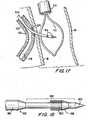
- a further stepis shown in FIG. 14 and involves insertion of snare structure 400 axially through the lumen of aortic access catheter 300, starting from the proximal portion of the catheter, until a distal portion of structure 400 extends from the distal end of catheter 300 into the space between artery 20 and pericardial membrane 40.
- Structure 400is preferably steerable (at least in its distal portion), and may include optical or video components to help the physician guide the distal portion of structure 400 to the vicinity of the distal portion 220 of catheter 200.
- the snare loop 412 on the distal end of wire 410may not be extended from the surrounding snare sleeve 420 as shown in FIG. 14 until after the distal-most portion of sleeve 420 has reached the vicinity of catheter portion 220.
- FIGS. 15a-jstructure 400 may be constructed in other ways, particularly preferred constructions of some of the components of that structure are shown in FIGS. 15a-j.
- Component 510includes stranded pull wire 512 securely attached at its distal end to metal bullet nose member 514. (In the assembled apparatus, member 514 forms the distal end of structure 400 (not including the possible further distal extension of snare loop 412 as shown in FIG. 14).)
- Component 520includes hypotube portion 522 secured at its distal end to flat wire coil portion 524.
- Component 530is a multilumen polymer tube. Portion 532 is preferably a relatively soft durometer polymer.
- Portions 534, 538, and 540are preferably a relatively hard durometer polymer.
- Portion 536is preferably an intermediate durometer polymer.
- Component 550is a hollow tubular braid of high tensile strength wires configured to fit concentrically around the outside surface of portions 536 and 538 of component 530.
- component 550may be formed by braiding several wires tightly around the outer surface of the appropriate portions of component 530.
- Component 560is a hollow polymer tube adapted to fit concentrically around the outside of component 550.
- component 560may be formed by extruding suitable polymer material around the outside of component 550 on component 530 so that the material of component 560 bonds to component 530 through interstices in component 550.
- Portion 562is preferably an intermediate durometer polymer (e.g., like portion 536).
- Portion 564is preferably a relatively hard durometer polymer (e.g., like portions 534, 538, and 540).
- bullet nose 514has a relatively small axial bore 514a for receiving and attaching the distal end of pull wire 512.
- Bullet nose 514also has two relatively large bores 514b and 514c.
- bore 514ais axially aligned with lumen 530a/530a' (or the similar diametrically opposite lumen) in component 530 (see FIGS. 15g and 15h).
- bores 514b and 514care aligned with lumens 530b and 530c in component 530.
- Component 530initially without portion 540, may be formed on several mandrels, each of which is subsequently pulled out the proximal end of component 530 to leave a respective one of the lumens in that component.
- Component 520may then be inserted into lumen 530a' from the proximal end of component 530.
- Component 510may then be added from the distal end of component 530 so that pull wire 512 passes through lumen 530a and component 520.
- Portion 540may then be attached as shown in more detail in FIG. 15j.
- FIG. 15jAn illustrative proximal handle and control portion of structure 400 is shown in FIG. 15j.
- An enlarged handle member 570is secured around portion 540 of component 530.
- Handle member 570has an axial slot 572 in which slide block 580 is captive in the radial direction of member 570 but slidable in the axial direction of member 570.
- a thumb screw 582is threaded into block 580 to act as a handle for sliding block 580 axially relative to member 570 when the thumb screw is sufficiently loosely threaded into block 580, and to act as a releasable lock for locking block 580 in any desired axial position along slot 572 when thumb screw 582 is threaded more tightly into block 580 and therefore against the outer surface of handle member 570.
- a side region of portion 540is notched at 542 to allow the proximal portion of pull wire 512 to come out of the side of portion 540 for looping through block 580.
- the loop in pull wire 512is fixed by a crimp 516 around the wire at the base of the loop. Accordingly wire 512 can be pulled proximally by various amounts relative to the remainder of structure 400 by sliding block 580 proximally relative to handle member 570. Pulling wire 512 proximally causes the relatively soft distal portion 532 of component 530 to curve in the direction of the side of component 530 that wire 512 is closest to. Relaxing wire 512 allows portion 532 to straighten out again.
- curvingis largely confined to distal portion 532 because that portion is made of the softest material and because component 520 substantially reduces any tendency of other axial portions of the apparatus to curve in response to tension in wire 512. All axial portions of structure 400 are, however, sufficiently flexible to pass along the patient's tubular body structure through aortic access catheter 300.
- Component 550helps structure 400 transmit torque from its proximal handle 570 to its distal end.
- the physiciancan use the combination of such torque and the ability to curve the distal portion 532 of structure 400 to maneuver the distal portion of that structure from the distal end of catheter 300 to a location adjacent catheter portion 220, all preferably inside pericardial membrane 400.
- Radiologic markersmay be provided on structure 400 to help the physician determine when the distal portion of that structure is properly located.
- One (or more) of the lumens through component 530 (and bullet nose 514)may be used to enable structure 400 to also function as an endoscope to aide in maneuvering the distal portion of structure 400 adjacent to catheter portion 220. As shown in FIG.
- optical fibers 502 extending along a lumen of component 530may be used to convey light from outside the patient to illuminate the interior of the patient just beyond bullet nose 514.
- Other parallel optical fibers 504may be used to convey the resulting illuminated scene back to an eyepiece or other optical or video viewing apparatus outside the patient.
- a luer 590may be attached to the proximal end of portion 540 as shown in FIG. 15j, if desired, so that the luer conduit 592 communicates with one (or more) of the lumens through components 530 (and bullet nose 514). This may provide the passage via which the above-mentioned optical fibers 502/504 exit from the remainder of the apparatus. It may also form a passageway for introducing fluids into or draining fluids from the patient adjacent bullet nose 514.
- notch 544provides the entrance point for snare loop 412 and wire 410.
- the portion of structure 400 around this lumentherefore forms what is referred to as the snare sleeve 420 in the earlier discussion of FIG. 14.
- passageways like 514b-c/530b-ccan be provided through elements 514 and 530.
- Components 410 and 412can take any of many forms, some alternatives being specifically illustrated and described later in this specification. For present purposes, however, it will be sufficient to assume that component 412 is a loop of wire which is secured to the distal end of wire 410 and which is resiliently biased to spring open when extended distally from the distal end of a lumen in sleeve 420 as shown in FIG. 14. Also as shown in FIG. 14, the distal portion of sleeve 420 is preferably positioned in the patient so that when loop 412 is extended distally from sleeve 420, loop 412 will receive a pierce structure passed out of coronary artery 20 via catheter portion 220 as will now be described.
- FIG. 16A further step is illustrated by FIG. 16 and involves inserting an elongated piercing structure 600 (e.g., primarily a metal wire or wire-like structure) into catheter 200 along the lumen 210 formerly used for guide wire 100. Because catheter portion 220 is now arched as shown in FIG. 16, the distal end of piercing structure 600 tends to follow lumen branch 210a out of catheter 200 and into contact with the interior surface of the side wall of coronary artery 20. The distal tip of piercing structure 600 is sufficiently sharp and structure 600 is sufficiently stiff that the distal tip of structure 600 can be pushed out through the coronary artery wall tissue (see also FIG. 17). Continued distal pushing of structure causes the portion outside coronary artery 20 to pass through snare loop 412.
- an elongated piercing structure 600e.g., primarily a metal wire or wire-like structure
- the distal portion of piercing structure 600is, however, preferably not strong enough, when outside coronary artery 20 and therefore unsupported by catheter lumen 210, to pierce or otherwise damage pericardial membrane 40.
- the main component of structure 600may be metal (e.g., nitinol) wire.
- Radiologically visible marker bands 610may be provided on the distal portion of piercing structure 600 to help the physician monitor the progress and position of that portion of structure 600.
- structure 600may be made of a radiologic (e.g., radio-opaque) material such as tungsten wire.
- FIG. 18An illustrative construction of the distal portion of structure 600 is shown in more detail in FIG. 18. There it will be seen that this part of structure 600 has a sharpened distal tip portion 620, which may be approximately 0.1 inches in length. Behind the distal tip is a relatively slender elongated portion 630. For example, portion 630 may have a diameter of approximately 0.006 inches and a length of approximately 1.575 inches. A hollow frusto-conical dilator 640 may be provided a short distance in from the distal end of portion 630. Just proximal of dilator 640 portion 630 may be wound with a radiologically viewable wire 650. For example, wire 650 may be gold or platinum wire.
- Dilator 640helps provide a gradual transition from the smaller diameter of portion 630 distal of wire 650 to the larger diameter produced by the addition of coil 650. Proximal of portion 630 structure 600 transitions gradually to relatively large diameter portion 660. For example, the diameter of portion 660 may be approximately 0.01 inches.
- Distal portions 620 and 630are stiff enough, when supported by lumen 210, to pierce the wall of coronary artery 20. At a greater distance from the support of lumen 210, however, portions 620 and 630 are preferably not stiff enough to pierce or otherwise damage pericardial membrane 40. In addition, distal portions 620 and 630 are not stiff enough to straighten out arched catheter portion 220 when portions 620 and 630 are inside catheter portion 220. The relatively slender distal portions 620 and 630 of structure 600 engage and pierce the wall of coronary artery 20 before the larger proximal portion 660 enters the curved portion 220 of catheter 200. Proximal portion 660 is made somewhat larger and therefore stiffer to help transmit the pushing force required to enable distal portions 620 and 630 to pierce the coronary artery wall.
- FIGS. 19a-cAnother illustrative way to provide marker bands 610 on piercing structure 600 is shown in FIGS. 19a-c.
- the distal portion 630 of structure 600is provided with several diametrically enlarged portions 632 axially spaced along portion 630.
- the distal portion of structure 600is inserted into the lumen of a heat shrinkable tube 670 which initially has an inner diameter which is slightly greater than the outer diameter of enlarged portions 632.
- a radiologically viewable adhesive 634is then injected into tube 670 so that the adhesive flows around the outside of distal portion 630.
- Tube 670is then heat shrunk to more closely conform to the outer diameter of portion 630, and adhesive 634 is then cured.
- Tube 670is then removed, and the extreme proximal and distal regions of adhesive 634 are tapered down to the diameter of portion 630.
- the resulting bands of adhesive 634 adjacent to or between portions 632provide radiologically viewable markers 610 on structure 600.
- a highly desirable feature of structure 600 no matter how it is constructedis that it has a substantially transitionless external profile to ensure continual passage through the arterial wall. Any slight edges may snag on the artery wall and prevent structure 600 from exiting the coronary artery.
- radio-opacitye.g., 610, 634, 650
- Radio-opacityallows efficient snaring of the distal end of structure 600 inside the pericardial sac.
- Radio-opaque markers 610can be plated, bands, or coils. Suitable marker materials include gold, tungsten, and platinum.
- Radio-opaque markers having predetermined spacingmay also be provided along the length of structure 600 to make it possible to use structure 600 to measure the length of graft needed between aorta 30 and coronary artery 20. This possible use of radiologic markers on structure 600 will become clearer as the description proceeds.
- the basic material of structure 600is preferably super-elastic nickel titanium (nitinol), but other possible materials include stainless steel, tantalum, and suitable polymers.
- structure 600may be made of a radiologically viewable material such as tungsten to eliminate the need for the above-described radiologic markers 610/650/634.
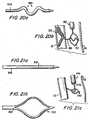
- FIGS. 20a and 20billustrate a feature that piercing structure 600 may be provided with to help ensure that the piercing structure does not inadvertently pierce pericardial membrane 40 after exiting from artery 20.
- a distal portion of piercing structure 600may be resiliently biased to deform into a serpentine shape 680 when it is no longer constrained to remain substantially straight by being inside catheter lumen 210.
- the distal portion of piercing structure 600exits from coronary artery 20 as shown in FIG. 20b, it takes on the above-described serpentine shape. When thus shaped, it is practically impossible to push the distal portion of piercing structure 600 through pericardial membrane 40.
- the serpentine shape of the distal portion of piercing structure 600also helps ensure that at least some of that structure stands off outside coronary artery 20, thereby facilitating snaring of that portion of structure 600 by snare loop 412.
- FIG. 21a-cAnother possible construction of the distal portion of structure 600 is shown illustratively in FIG. 21a-c.
- an axially medial portion of structure 600 close to the sharpened distal tipis cut through axially as indicated at 690 in FIG. 21a.
- the two lateral halves of the cut portion of structure 600may be resiliently biased to spring apart as shown in FIG. 21b when unconstrained by lumen 210. While in lumen 210, the two lateral halves of cut structure 600 remain together, and with the support of lumen 210 the structure has sufficient column stiffness to pierce the wall of artery 20. Shortly after emerging from artery 20, however, the two lateral halves of structure 600 can separate as shown in FIG.
- structure 600loses its ability to pierce any further tissue such as pericardial membrane 40.
- the loop 692 that forms in the distal-most portion of structure 600 outside artery 20provides an alternative means by which snare structure 400 can engage structure 600.
- a hook 412acan be used to hook onto loop 692 as shown in FIG. 21c.
- the distal portion of structure 600may be or may include a ferromagnetic material
- structure 410may include a distal magnet for attracting and holding that ferromagnetic material.
- the distal portion of structure 410may include a pliers-like gripper for closing on and gripping the distal portion of structure 600.
- both of these structuresmay be made of radiologic materials such as tungsten to permit radiologic observation of the snaring maneuvers.
- a further stepincludes pulling structure 410 back proximally in order to pull structure 600 into structure 400.
- the immediately above-mentioned stepmay be preceded by operating or manipulating structure 400 to close loop 412 on structure 600, and preferably also to deflect structure 600 around a portion of loop 412.
- FIG. 22shows shifting structure 400 distally relative to loop 412 to cause the loop to close and to deform structure 600 into what is effectively a hook through the closed loop. This provides a very secure link between structures 410 and 600.
- structure 600is pulled into structure 400.
- additional length of structure 600may be pushed into the patient at approximately the same rate that structure 410 is being pulled out of the patient.
- structure 410may be pulled completely out of the patient, and structure 600 may extend continuously through the patient from its initial entry point to the initial entry point of structure 410.
- the condition of the portions of the patient and apparatus shown in FIG. 22may now be as shown in FIG. 23.
- a further stepis to withdraw structure 400 from the patient.
- Structure 200may also be withdrawn from the patient or is at least proximally retracted somewhat.
- the condition of the relevant portion of the patient and the apparatus after these operationsmay be as shown in FIG. 24. (FIG. 24 illustrates the case in which structure 200 is proximally retracted rather than being fully withdrawn from the patient at this stage.)
- structure 600To help provide a graft which connects to coronary artery 20 with an acute angle between the graft and the upstream portion of the coronary artery, it may be desirable to construct structure 600 so that a portion of that structure can be made to extend down into the downstream portion of the coronary artery beyond the point at which structure 600 passes through the side wall of the artery.
- FIGS. 25 and 26An example of this type of structure 600 is shown in FIGS. 25 and 26. (FIG. 25 also illustrates a case in which structure 200 is completely withdrawn from the patient after structure 600 has been fully placed in the patient.)
- structure 600may be constructed as shown in FIG. 26 with an axially medial portion 662 having significantly greater flexibility than the axially adjacent portions of that structure.
- structure 600may have reduced diameter in region 662 to increase its flexibility in that area.
- Portion 662may be provided with a radiologic marker 664 (e.g., a wire of radio-opaque material wrapped around that portion of structure 600) to facilitate proper placement and other observation of portion 662 in the patient. Marker 664 preferably does not interfere with the increased flexibility of portion 662.
- a radiologic marker 664e.g., a wire of radio-opaque material wrapped around that portion of structure 600
- structure 600is shifted axially in the patient until portion 662 is inside coronary artery 20 adjacent the point at which structure 600 passes through the side wall of the artery. This can be determined by radiologic observation of marker 664. Then both end portions of structure 600 can be pushed into the patient to cause structure 600 to essentially fold or prolapse at portion 662 and to push folded portion 662 down into the downstream portion of artery 20 as shown in FIG. 25. This causes the portion of structure 600 which is outside the upstream portion of artery 20 to form an acute angle A with the upstream artery portion. Such an acute angle A may be a preferable angle of approach for the bypass graft which is to be installed along structure 600 as described elsewhere in this specification.
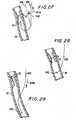
- FIGS. 27-29Another alternative (apparatus and method) for re-routing structure 600 in the patient (e.g., to achieve an acute angle approach of structure 600 to the outer surface of coronary artery 20) is shown in FIGS. 27-29.
- the proximal end of the portion of structure 600 that extends up and out of the patient via coronary artery 20is preferably provided with an atraumatic end 602.
- atraumatic end 602is a ball which covers what might otherwise be a relatively sharp end of structure 600.
- structure 600which, as has been said, may be a metal wire
- structure 600causes what remains of structure 600 in the vicinity of the coronary artery side wall aperture to straighten.
- Thiscauses the end 602 of structure 600 to move in the downstream direction along coronary artery 20 as shown in FIG. 28.
- the next stepis to begin to push structure 600 back into the patient as shown by arrow 604b in FIG. 29.
- Thiscauses end 602 to move in the downstream direction along the coronary artery lumen as is also shown in FIG. 29, thereby ultimately giving structure 600 a new routing immediately outside coronary artery 20 like the routing of the corresponding portion of structure 600 in FIG. 25.
- structure 600is sufficiently laterally flexible to enable a distal part of that structure to extend inside the lumen in the upper portion of coronary artery 20, while a proximal part of structure 600 extends axially along a path 606 that is outside the upper portion of the coronary artery and that forms an acute angle C with a line 608 parallel to the upper portion of the artery.
- path 606extends back along the outside of the upper portion of artery 20.
- At least the depicted portion of structure 600is also sufficiently resilient so that when the part of structure 600 that remains in the lumen in the upper portion of coronary artery 20 becomes too short to continue to be constrained or guided by that artery portion, the part of structure 600 that remains in the artery switches resiliently into the lower portion of the artery as shown in FIG. 28. This switching happens automatically as a result of structure 600 resiliently tending to straighten when it is not otherwise deflected or constrained by its contact with the interior surfaces of artery 20. At least the depicted portion of structure 600 is also sufficiently laterally stiff that the distal part can be pushed down into the lower portion of artery 20 when the proximal part is pushed in the distal direction as indicated by arrow 604b in FIG. 29.
- end 602is radially enlarged relative to the axially adjacent portion of structure 600 helps prevent end 602 from being inadvertently pulled proximally out of artery 20 when the structure approaches the condition shown in FIG. 28 and before structure 600 begins to be pushed into the artery again as shown in FIG. 29.
- atraumatic end 602may itself be made of a radiologic material such as gold, platinum, silver, tungsten, or any other suitable substance.
- the patientWhen the condition of the patient is as shown in FIG. 24, 25, or 29, depending on the apparatus and procedural options selected, the patient is ready for installation of a tubular bypass graft along structure 600 between the distal end of structure 300 and the point at which structure 600 passes through the side wall of coronary artery 20.
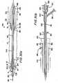
- FIG. 30An illustrative embodiment of a tubular graft 42 and structure 800 for delivering and installing the graft along structure 600 is shown in FIG. 30 (which comprises FIGS. 30a and 30b connected between the right in FIG. 30a and the left in FIG. 30b). It should be understood that the portion of structure 800 that is shown in FIG. 30b remains outside the patient at all times, and that structure 800 may have any desired length between the distal portion shown in FIG. 30a and the proximal portion shown in FIG. 30b.
- Graft 42is shown in FIG. 30 with a connector 50 at its proximal end for use in connecting the graft to the side wall of the patient's aorta 30.
- Connector 50may be of a type shown in commonly assigned, concurrently filed U.S.
- Graft 42is also shown in FIG. 30 with a connector 60 at its distal end for use in connecting the graft to the patient's coronary artery 20.
- Connector 60may be of a type shown in commonly assigned, concurrently filed U.S. patent application No. 09/187,361, which is hereby incorporated by reference herein in its entirety.
- Graft 42is assumed to be a length of the patient's saphenous vein which has been harvested for use in the coronary artery bypass procedure being described. It will be understood however, that other natural body conduit can be used for graft 42, or that graft 42 can be a synthetic graft or a combination of natural and synthetic materials. It will also be understood that the particular connectors 50 and 60 shown in FIG. 30 are only illustrative and that other connectors can be used instead if desired. For example, connectors of the type shown in commonly assigned, concurrently filed U.S. patent application No. 09/186,774, which is hereby incorporated by reference herein in its entirety, can be used for distal (coronary artery) connector 60. Connectors of the type shown in above-mentioned application No. 09/187,335 can also be used for distal connector 60.
- Tube 810is configured for disposition substantially concentrically around structure 600 and for sliding axially along that structure.
- Tube 810may be made of stainless steel hypotube so that it can bend laterally to follow whatever straight or curved path structure 600 has in the patient.
- Tube 810is axially strong enough to transmit pushing or pulling force between proximal actuator structure 812 and distal tip structure 820, both of which are secured to tube 810 at respective opposite ends thereof.
- Distal tip structure 820has a substantially conical distal-most outer surface portion 822 and a more proximal, substantially cylindrical surface portion 824.
- the cone angle B of conical surface portion 822is preferably relatively small (e.g., in the range from about 5° to about 15°, more preferably in the range from about 5° to about 10°).
- Tip structure 820includes an annular recess 826 in its proximal portion for receiving the distal-most portions of structure 830/832 (described below), connector 60, and graft conduit 42.
- Tube 830is disposed substantially concentrically around tube 810 and is slidable axially relative to tube 810.
- Annular balloon 832is secured to a distal portion of tube 830.
- Actuator structure 834 and luer connector 836are secured to a proximal portion of tube 830.
- the side wall of tube 830preferably includes a lumen (not shown) which extends from connection 836 to the interior of balloon 832 so that the balloon can be inflated or deflated by appropriately directed fluid flow through that lumen.
- Balloon 832is shown deflated in FIG. 30.
- Tube 830is again sufficiently laterally flexible to allow structure 800 to follow whatever path structure 600 has in the patient.
- Tube 830is also axially strong enough to transmit pushing or pulling force axially between balloon 832 and actuator structure 834, although the axial force tube 830 is required to transmit is typically less than the axial force tube 810 must transmit.
- suitable materials for tube 830include polymers such as nylon, Teflon, and polyethylene.
- Connector 60is disposed annularly around balloon 832.
- connector 60has its initial, relatively small, circumferential size.
- Fingers 62extend radially out from the main portion of connector 60 in order to pass through the distal end portion of graft conduit 42 and thereby secure the graft to the connector.
- Other graft-to-connector securing meanssuch a sutures may be used instead of or in addition to fingers 62.
- Connector 60can be plastically circumferentially enlarged by inflation of balloon 832 as described below when tip structure 820 is shifted distally relative to balloon 832 to fully expose elements 832 and 60 and the distal end portion of graft conduit 42. In the condition shown in FIG.
- tip structure 820shields and protects elements 832, 60, and 42 and provides a smooth profile for facilitating entry of these elements into the patient's coronary artery through an aperture in the side wall of that artery (see the following discussion of use of apparatus 800). Additional details regarding suitable constructions of connector 60 will be found in above-mentioned application No. 09/187,361.
- structure 800The components of structure 800 that have thus far been described are particularly associated with positioning and control of distal connector 60. The further components of structure 800 that will now be described are particularly associated with positioning and control of proximal connector 50.
- Tube 840is disposed substantially concentrically around tube 830.
- Tube 840is slidable axially along tube 830 by proximal actuator 842, but preferably includes a proximal structure 844 (e.g., a collet-type structure) for allowing tube 840 to be releasably locked to tube 830 at various axial locations along tube 830.
- a proximal structure 844e.g., a collet-type structure
- tubes 830 and 840can be shifted axially relative to one another to accommodate any desired length of graft conduit 42.
- structure 844can be operated to lock tubes 830 and 840 relative to one another for that length of graft.
- Annular connector 50is shown in FIG. 30 in its initially relatively small circumferential size.
- Connector 50is resiliently biased to circumferentially enlarge to a larger final circumferential size, but is prevented from doing so by the surrounding distal cone portion 846 of tube 840.
- Most of connector 50is disposed annularly around tube 840, but distal portions 52a of the connector enter a proximal-facing annular recess in cone portion 846 which helps to maintain the initial small circumferential size of the connector.
- Proximal of portions 52a connector 50includes radially outwardly extending graft retention fingers 52b that pass through the proximal end portion of graft conduit 42 to secure the connector to the graft conduit.
- Other graft-to-connector securing meanssuch as sutures can be used instead of or in addition to fingers 52b.
- proximal of fingers 52b connector 50includes "inside" fingers 52c and "outside” fingers 52d.
- Inside fingers 52care resiliently biased to spring radially out, but are initially held relatively parallel to the longitudinal axis of structure 800 by being confined inside a distal end portion of tube 850.
- Outside fingers 52dare also resiliently biased to spring radially out, but are initially held relatively parallel to the longitudinal axis of structure 800 by being confined inside catheter 300 (which is already in place in the patient as shown, for example, in FIG. 25).
- Tube 850is disposed substantially concentrically around tube 840 and is axially slidable relative thereto by proximal actuator 852.
- Tube 860is disposed substantially concentrically around tube 850 and is axially slidable relative thereto by proximal actuator 862. The distal end of tube 860 is axially aligned with proximal portions of fingers 52d.
- Each of tubes 840, 850 and 860is sufficiently laterally flexible so as not to interfere with the ability of structure 800 to follow any path that structures 300 and 600 have in the patient.
- Each of tubes 840, 850, and 860is also axially strong enough to transmit necessary forces axially along the tube between the associated proximal actuator 842, 852, or 862 and the operative distal end portion of the tube.
- additional details of suitable constructions for connector 50can be found in above-mentioned application No. 09/187,335.
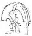
- Structure 800with a suitable length of graft 42 and associated connectors 50 and 60 mounted thereon as shown in FIG. 30, is inserted axially into the patient along structure 600 and inside catheter 300 as shown in FIG. 31. At the distal end of catheter 300, the distal portion of structure 800 emerges from the catheter and therefore from the patient's aorta 30 and continues to follow structure 600 toward the side wall of the patient's coronary artery 20.
- structure 800continues to be pushed distally until distal tip structure 820 is entirely inside the coronary artery, as is connector 60 and the distal portion of graft 42. Then tube 830 is held stationary while tube 810 continues to be pushed distally. This causes distal tip structure 820 to separate from connector 60 and the associated distal portions of graft 42 and structure 830/832 (see FIG. 33).
- Balloon 832is then inflated to circumferentially plastically enlarge connector 60 as shown in FIG. 33.
- Connector 60thereby presses the surrounding distal portion of graft 42 radially out against the inner surface of the coronary artery wall, which both holds the distal end of the graft inside the coronary artery and provides a hemodynamic seal between the graft and the coronary artery.
- connector 60can be long enough to extend upstream inside graft 42 and out the aperture in the coronary artery side wall to help hold open the graft where it passes through that aperture and to help the graft seal the aperture.
- balloon 832can be deflated again.
- FIG. 34illustrates the condition of the portion of structure 800 in the vicinity of connector 50 when the distal portion of the apparatus is as shown in FIG. 33.
- outside fingers 52d of connector 50are preferably just outside the side wall of aorta 30.
- the next stepis to proximally retract catheter 300 while holding tubes 840, 850, and 860 stationary. This releases outside fingers 52d to spring radially out as shown in FIG. 35. Tube 840 can then be pulled proximally back somewhat to snug fingers 52d up against the wall of aorta 30 as is also shown in FIG. 35.
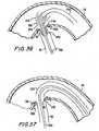
- the next stepis to proximally retract tube 850. This allows inside fingers 52 to spring radially out inside the side wall of the aorta 30 as shown in FIG. 36.
- the next stepis to shift tube 840 distally, which releases connector 50 from the circumferential restraint of the distal portion 846 of that tube. This allows connector 50 to resiliently fully enlarge to its final, relatively large circumference as shown in FIG. 37.
- All of structures 300, 600, and 800can then be withdrawn proximally from the patient. This leaves the final condition of the patient as shown in FIG. 38, i.e., with connector 50 providing an anastomotic connection between the side wall of aorta 30 and the proximal end of graft conduit 42, and with connector 60 providing an anastomotic connection between the distal end of graft conduit 42 and the inside of coronary artery 20 downstream from occlusion 22.
- the downstream portion of coronary artery 20is thereby supplied with aortic blood via bypass graft conduit 42.
- a desirable feature of structure 800is the fact that the proximal and distal connector delivery components are independent of one another in terms of deployment controls.
- the distal connector delivery and deployment componentsare coaxially inside the proximal connector delivery and deployment components.
- Radiologic markers on structure 800 and/or on connectors 50 and 60can be used to help the physician properly position these components relative to circulatory system conduits 20 and 30 during the operational steps described above.
- the present inventionis suitable for adding a new length of graft conduit to a patient's circulatory system between two points on that system that can be quite widely spaced from one another (as in the case of the aorta, on the one hand, and a coronary artery beyond an occlusion, on the other hand).
- the graftis installed outside the patient's existing circulatory system through the space in the patient between the above-mentioned two endpoints.
- the graftis installed along a path initially defined by structure 600. The invention does not rely on tunneling through tissue masses in the patient to provide a path for the graft.
Landscapes
- Health & Medical Sciences (AREA)
- Life Sciences & Earth Sciences (AREA)
- Heart & Thoracic Surgery (AREA)
- Engineering & Computer Science (AREA)
- Biomedical Technology (AREA)
- Surgery (AREA)
- Animal Behavior & Ethology (AREA)
- General Health & Medical Sciences (AREA)
- Public Health (AREA)
- Veterinary Medicine (AREA)
- Medical Informatics (AREA)
- Pulmonology (AREA)
- Nuclear Medicine, Radiotherapy & Molecular Imaging (AREA)
- Molecular Biology (AREA)
- Anesthesiology (AREA)
- Vascular Medicine (AREA)
- Biophysics (AREA)
- Hematology (AREA)
- Oral & Maxillofacial Surgery (AREA)
- Gastroenterology & Hepatology (AREA)
- Cardiology (AREA)
- Child & Adolescent Psychology (AREA)
- Transplantation (AREA)
- Prostheses (AREA)
- Media Introduction/Drainage Providing Device (AREA)
- Medicines Containing Plant Substances (AREA)
- Pharmaceuticals Containing Other Organic And Inorganic Compounds (AREA)
- Surgical Instruments (AREA)
Abstract
Description
This invention relates to medical apparatusand methods, and more particularly to apparatus andmethods for installing a tubular graft in a patient forsuch purposes as bypassing an occlusion in thepatient's tubular body conduit structure.
Goldsteen et al. U.S. patent 5,976,178, whichis hereby incorporated by reference herein in itsentirety, shows, among other things, apparatus andmethods for installing a graft conduit in a patient,with most or all of the work being done intraluminallythrough the patient's existing body conduit structure.Testing and further development work have suggestedthat it would be advantageous to improve and/or augmentsome aspects of apparatus and/or methods of the kindshown in the above-mentioned Goldsteen et al.reference.
In view of the foregoing, it is an object ofthis invention to improve and simplify various aspectsof apparatus and methods of the general type shown inthe above-mentioned Goldsteen et al. reference.
It is another object of this invention toprovide additional and/or alternative apparatus and/ormethods for certain aspects of technology of thegeneral type shown in the Goldsteen et al. reference.
These and other objects of the invention areaccomplished in accordance with the principles of theinvention by providing improved apparatus and methodsfor installing a guide structure in a patient betweentwo locations along the patient's circulatory systemthat are to be connected by a bypass graft. The guidestructure extends between those two locations outsidethe circulatory system (albeit within the patient) andis used to guide the bypass graft into place betweenthose two locations. The guide structure is preferablyinstalled in the patient intraluminally (i.e., vialumens of the patient's circulatory system), althoughthere is a portion of the guide structure whichultimately extends outside the circulatory system asmentioned above. A portion of the guide structure maybe re-routable in the circulatory system to improve thealignment of the guide structure for purposes ofoptimal guidance of the bypass graft into place. Forexample, the guide structure may be re-routed so that,whereas both ends of the guide structure initiallyextend out of the patient, only one end of the re-routedguide structure extends out of the patient,while the other end of the guide structure dead-ends inthe patient. Again, the new routing of the guidestructure may improve its ability to guide the bypassgraft into a desired alignment in the patient.
Improved apparatus and methods for deliveringa bypass graft conduit into the patient along the guide structure are also provided. For example, the graftdelivery structure may include a very gradually tapereddistal nose portion to facilitate entry of theapparatus into the patient's circulatory system at oneend of the graft installation site. Improvedconnectors for attaching one or both ends of the graftconduit to the patient's circulatory system may also beused.
Further features of the invention, its natureand various advantages will be more apparent from theaccompanying drawings and the following detaileddescription of the preferred embodiments.
Although the invention has other possibleuses, the invention will be fully understood from the following explanation of its use in providing a bypassaround an obstruction in a patient's vascular system.
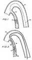
As shown in FIG. 1, an early stage in anillustrative coronary artery bypass procedure inaccordance with the invention includes introducing alongitudinal guide member 100 (typically a guide wire,and therefore sometimes referred to as such herein)into the patient's circulatory system across thecoronary artery occlusion 22 to be bypassed. Forexample,guide wire 100 may be introduced into thepatient via a femoral (leg) artery (not shown). Fromthe femoral artery,guide wire 100 may be pushedintraluminally into the patient'saorta 30, and fromthe aorta into thecoronary artery 20 that hasocclusion 22. Advancement ofguide wire 100 may bestopped at any desired point after the distal portionof the guide wire has passed throughocclusion 22.
Afterguide wire 100 is acrossocclusion 22as shown in FIG. 1, a catheter or catheter-likestructure 200 is introduced into the patient alongguide wire 100 as shown in FIG. 2. A more detailedview of a distal portion ofcatheter 200 is shown inFIG. 3, wherein it can be seen that the catheter has anaxially extendinglumen 210 for containingguidewire 100 as the catheter is advanced along the guidewire.Guide wire 100 facilitates passage of the distalportion ofcatheter 200 throughocclusion 22 as shownin FIG. 2.
After the distal portion ofcatheter 200 haspassed throughocclusion 22 as shown in FIG. 2,guidewire 100 is pulled proximally out of the catheter andout of the patient.
Amedial portion 220 ofcatheter 200 ispreferably constructed to form a laterally extending arch as shown in FIGS. 4 and 5 whenguide wire 100 iswithdrawn from the catheter. For example,catheter 200may be made so that it resiliently tends to form anarch of a predetermined lateral extent when it is freedfrom the straightening effect ofguide wire 100. Thearch height H may be specifically designed tocomplement various artery sizes (e.g., 3.0 mm, 3.5 mm,4.0 mm, etc., diameter vessels). For example, the archheight may be selected to be approximately the same asor slightly greater than the inside diameter of theartery 20 into which the catheter will be inserted. Inthis way the bases of the arch (in contact with oneside of the interior of the artery wall at axiallyspacedlocations 20a and 20b) will push the apex of thearch against the diametrically opposite side of theartery wall (atlocation 20c, which is axiallymediallocations 20a and 20b).
Thelumen 210 incatheter 200 has a sidebranch 210a which exits from the side wall of thecatheter at or near the apex of the above-describedarch in the catheter.Catheter portion 220, whichforms the above-described arch, is preferably loadedwith conventional radio-opaque filler (e.g., asindicated by the small plus signs in FIG. 17) to helpthe physician using the apparatus to radiologicallylocate and properly orientcatheter portion 220 in thepatient's artery. Portions ofcatheter 200 which aredistal and proximal ofportion 220 may be less radio-opaqueto help highlightportion 220. The objective isto position lumen branch 210a at the approximatelocation alongartery 20 at which it is desired toconnect one end of a bypass graft to the artery.Radiologic observation may be further aided byproviding a radiologically viewable (e.g., radio-opaque) marker band around the exit from lumenbranch 210a (e.g., as shown at 224 in FIG. 17). (As ageneral matter, the term "radiologic" is frequentlyused herein as a generic term for any kind ofradiologically viewable (e.g., radio-opaque) materialor structure.)
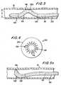
Additional details of preferredconstructional features ofcatheter 200 are shown inthe typical cross sectional view of FIG. 6. As shownin FIG. 6 the catheter tube preferably has aninnerliner 230 of polytetrafluoroethylene to minimizeinternal friction. A reinforcing layer such as a braidofwires 250 may be included to enable the catheter totransmit torque and to provide kink resistance.Polymer layer 240 (e.g., Pebax or nylon) providessupport and curve retention.Internal lumen 210preferably extends along the entire length of thecatheter and is used to allow the catheter to trackoverguide wire 100 as described above, and tosubsequently guide a longitudinal piercing structure tothe point on the wall ofartery 20 where it is desiredto connect one end of a bypass graft. (The piercingstructure and its use will be described in more detailshortly.) The distal tip portion ofcatheter 200 maybe made especially soft and/or the external surface ofthe catheter may be coated with polytetrafluoroethyleneto enhance the ability of the catheter to pass throughan occlusion likeocclusion 22. A soft tip also helpsmakecatheter 200 atraumatic. The distal tip portionof the catheter may be tapered in the distal directionfor similar reasons. Overall, the transversedimensions ofcatheter 200 are preferably made small(e.g., less than 3 French or 1.0 mm) to facilitateintroduction of the catheter into the patient, especially a relatively small coronary artery and theeven smaller passageway through theocclusion 22 inthat artery. Although polytetrafluoroethylene has beenmentioned for low friction layers or coatings, othermaterials such as silicone and hydrophilic substancescan be used instead of polytetrafluoroethylene ifdesired.Arched section 220 is made stiff enough toprovide backup support for piercing the coronary arterywall as described below, as well as stability of thecatheter in the coronary artery. Proximal sections ofcatheter 200 are constructed to provide appropriatepushability and trackability of the catheter alongguide wire 100. For example,catheter 200 may havediffering flexibility at different locations along itslength.
As an alternative to having amedial portion 220 ofcatheter 200 arch as shown in FIGS. 4 and 5 whenguide wire 100 is withdrawn from the catheter, a distalportion 220' of the catheter may be configured todeflect or curve to the side whenguide wire 100 iswithdrawn as shown in FIG. 5a.Catheter 200 in FIG. 5ais positioned incoronary artery 20 so that afterportion 220' curves to the side, the distal end oflumen 210 points to a location on the inside of theside wall of the artery similar to the location of theapex of the arch 220 in FIG. 5 (i.e., the location onthe coronary artery side wall at which it is desiredfor a piercing structure exiting from the distal end oflumen 210 to pierce the side wall of the coronaryartery as referred to above and as described in moredetail below). Thus in the embodiment shown in FIG.5a,lumen 210 does not need a separate, additional sideexit 210a for the piercing structure because the distalend oflumen 210 can be used as the exit for the piercing structure. In other respects embodiments ofthe type shown in FIG. 5a can be constructed andoperated similarly to embodiments of the type shown inFIG. 5 and described above. The deflection of portion220' is preferably such that after deflection one sideofcatheter 200 bears on the inside of one side of thecoronary artery side wall atlocation 20d in order tomaintain the distal end of the catheter close to or incontact with the other side of the coronary artery sidewall at axially spaced location 20e. Further depictionand explanation of the invention will be made withreference to embodiments of the FIG. 5 type, but itwill be understood that embodiments of the FIG. 5a typecan be used instead if desired.
While it is not necessary to perform theabove-described coronary artery access steps of theinvention first, it may be preferable to do so to makesure thatcatheter 200 can be passed throughocclusion 22 before committing to the other steps thatwill now be described.
A further step in accordance with theinvention relates to accessing the aortic end of thedesired bypass aroundocclusion 22. (See also Berget al. U.S. patent application No. 09/014,759, filedJanuary 28, 1998 and hereby incorporated by referenceherein in its entirety, for additional and/oralternative apparatus and/or methods usable in theaortic access that will now be described.) Anothercatheter or catheter-like structure 300 is introducedintraluminally into the aorta as shown in FIG. 7. Likeguide wire 100 andcatheter 200,catheter 300 ispreferably introduced into the patient at a locationremote from the coronary area. For example,catheter 300 may be introduced into the patient via a femoral artery. Also likeguide wire 100 andcatheter 200, the distal portions ofcatheter 300 arepreferably remotely controlled from proximal portionsof the apparatus which remain outside the patient atall times.
A preferred construction ofcatheter 300 isshown in more detail in FIG. 8. (See also Berg et al.U.S. patent application No. 09/010,367, filedJanuary 21, 1998 and hereby incorporated by referenceherein in its entirety, for possible additional and/oralternative features forcatheter 300.) There it willbe seen thatcatheter 300 preferably includespilotwire 310 disposed substantially concentrically insidehollowtubular needle catheter 320.Needlecatheter 320 is disposed substantially concentricallyinside hollowtubular cutter catheter 330, which inturn is disposed substantially concentrically insidehollow tubularaortic access catheter 340.
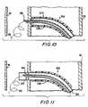
The next step is to push the distal portionofpilot wire 310 out of the distal end ofneedle catheter 320 and into the space betweenaorta 30 andpericardial membrane 40 as shown in FIG. 10.Wire 310is preferably too flexible where not supported byneedle catheter 320 to piercepericardial membrane 40.A quantity ofwire 310 therefore deposits itself in thespace betweenaorta 30 andmembrane 40 as shown inFIG. 10.
The next step is to pushcutter catheter 330in the distal direction so that a sharpened distal endofcatheter 330 makes an annular cut through the wallofaorta 30 as shown in FIG. 11. If provided as shownin FIG. 9a,barbs 322 onneedle catheter 320 help holdthe toroidal "doughnut" 30a of aorta wall tissue thatis cut away bycutter catheter 330 on the distalportion ofcatheter 320.Cutter catheter 330 may berotated about its central longitudinal axis to help itcut through the aorta wall tissue. After passingthrough the aorta wall as shown in FIG. 11, the distalportion ofcutter catheter 330 tends to followpilotwire 310 in the space betweenaorta 30 andpericardialmembrane 40. This helps preventcutter catheter 330from inadvertently cutting throughmembrane 40. Atypical diameter forcutter catheter 330 isapproximately 3mm. The cutter catheter shaft functionsas a plug through the aperture in the aorta wall thatthe cutter catheter has formed. This prevents bloodflow from the aorta into the pericardial space.
The next step is to push the distal portionofaortic access catheter 340 through the aperture inthe aorta wall that the cutter catheter has formed asshown in FIG. 12. To do this,aortic accesscatheter 340 uses the shaft ofcutter catheter 330 as aguide. Assuming that the diameter of the cuttercatheter is approximately 3mm, the diameter ofaortic access catheter 340 may be approximately 5mm. Theresulting expansion of the aortic opening from 3mm to5mm makes use of the elastic recoil of the aorta tohelp seal the aortic opening aroundcatheter 340,thereby ensuring no blood leakage into the pericardialspace whilecatheter 340 is positioned through theaorta wall. The outer surface ofcatheter 340 may becoated with a hydrophilic material to facilitateadvancement through the aorta wall. If the aorta walldoes not provide sufficient elastic recoil, selectivelyinflatable annular sealing balloons 340a and/or 340bcan be added tocatheter 340 to provide sealing (see,for example, Berg et al. U.S. patent applicationNo. 09/010,367, filed January 21, 1998, which is herebyincorporated by reference herein in its entirety).When inflated, balloons 340a and 340b bear resilientlyon the respective inner and outer surfaces of the aortawall annularly around the aperture through that wall.Balloons 340a and/or 340b may also be desirable to helpanchor the distal end ofcatheter 340 through theaperture in the aorta wall. In particular,balloon 340a (which is only inflated aftercatheter 340has been pushed through the aorta wall aperture) helpspreventcatheter 340 from being inadvertently pulledback out of the aorta wall aperture.Balloon 340bhelps preventcatheter 340 from being pushed too farthrough the aorta wall aperture.
The next step, shown in FIG. 13, is to pullall ofcomponents catheter 340. The aorta wall tissue portion 30a cutaway bycutter catheter 330 comes out of the patientwithcomponents needle catheter 320 help ensure that tissueportion 30a is thus removed from the patient.
A further step is shown in FIG. 14 andinvolves insertion ofsnare structure 400 axiallythrough the lumen ofaortic access catheter 300,starting from the proximal portion of the catheter,until a distal portion ofstructure 400 extends fromthe distal end ofcatheter 300 into the space betweenartery 20 andpericardial membrane 40.Structure 400is preferably steerable (at least in its distalportion), and may include optical or video componentsto help the physician guide the distal portion ofstructure 400 to the vicinity of thedistal portion 220ofcatheter 200. Thesnare loop 412 on the distal endofwire 410 may not be extended from the surroundingsnare sleeve 420 as shown in FIG. 14 until after thedistal-most portion ofsleeve 420 has reached thevicinity ofcatheter portion 220.
Althoughstructure 400 may be constructed inother ways, particularly preferred constructions ofsome of the components of that structure are shown inFIGS. 15a-j. In FIGS. 15a-e horizontally alignedportions are superimposed on one another when thesevarious components are assembled instructure 400.Component 510 includes strandedpull wire 512 securelyattached at its distal end to metalbullet nosemember 514. (In the assembled apparatus,member 514forms the distal end of structure 400 (not includingthe possible further distal extension ofsnare loop 412as shown in FIG. 14).)Component 520 includeshypotubeportion 522 secured at its distal end to flatwire coilportion 524.Component 530 is a multilumen polymertube. Portion 532 is preferably a relatively softdurometer polymer.Portions Portion 536 is preferably an intermediate durometer polymer.Component 550 is a hollow tubular braid ofhigh tensile strength wires configured to fitconcentrically around the outside surface ofportions component 530. For example,component 550 may be formed by braiding several wirestightly around the outer surface of the appropriateportions ofcomponent 530.Component 560 is a hollowpolymer tube adapted to fit concentrically around theoutside ofcomponent 550. For example,component 560may be formed by extruding suitable polymer materialaround the outside ofcomponent 550 oncomponent 530 sothat the material ofcomponent 560 bonds tocomponent 530 through interstices incomponent 550.Portion 562 is preferably an intermediate durometerpolymer (e.g., like portion 536).Portion 564 ispreferably a relatively hard durometer polymer (e.g.,likeportions
As can be seen in FIG. 15f,bullet nose 514has a relatively small axial bore 514a for receivingand attaching the distal end ofpull wire 512.Bulletnose 514 also has two relativelylarge bores 514b and514c. In the assembled structure, bore 514a is axiallyaligned with lumen 530a/530a' (or the similardiametrically opposite lumen) in component 530 (seeFIGS. 15g and 15h). Similarly, in the assembledstructure, bores 514b and 514c are aligned withlumens component 530.
An illustrative proximal handle and controlportion ofstructure 400 is shown in FIG. 15j. Anenlarged handle member 570 is secured aroundportion 540 ofcomponent 530.Handle member 570 has anaxial slot 572 in which slideblock 580 is captive inthe radial direction ofmember 570 but slidable in theaxial direction ofmember 570. Athumb screw 582 isthreaded intoblock 580 to act as a handle for slidingblock 580 axially relative tomember 570 when the thumbscrew is sufficiently loosely threaded intoblock 580,and to act as a releasable lock for lockingblock 580in any desired axial position alongslot 572 whenthumbscrew 582 is threaded more tightly intoblock 580 andtherefore against the outer surface ofhandlemember 570.
A side region ofportion 540 is notched at542 to allow the proximal portion ofpull wire 512 tocome out of the side ofportion 540 for looping throughblock 580. The loop inpull wire 512 is fixed by acrimp 516 around the wire at the base of the loop.Accordingly wire 512 can be pulled proximally byvarious amounts relative to the remainder ofstructure 400 by slidingblock 580 proximally relativeto handlemember 570. Pullingwire 512 proximallycauses the relatively soft distal portion 532 ofcomponent 530 to curve in the direction of the side ofcomponent 530 thatwire 512 is closest to.Relaxingwire 512 allows portion 532 to straighten out again.The above-described curving is largely confined todistal portion 532 because that portion is made of the softest material and becausecomponent 520substantially reduces any tendency of other axialportions of the apparatus to curve in response totension inwire 512. All axial portions ofstructure 400 are, however, sufficiently flexible topass along the patient's tubular body structure throughaortic access catheter 300.
Aluer 590 may be attached to the proximalend ofportion 540 as shown in FIG. 15j, if desired, sothat theluer conduit 592 communicates with one (ormore) of the lumens through components 530 (and bullet nose 514). This may provide the passage via which theabove-mentionedoptical fibers 502/504 exit from theremainder of the apparatus. It may also form apassageway for introducing fluids into or drainingfluids from the patientadjacent bullet nose 514.
Another of the lumens through component 530(and bullet nose 514) is opened outside the patient viathe notch 544 (FIG. 15j) in a proximal part ofportion 540.Notch 544 provides the entrance point forsnare loop 412 andwire 410. The portion ofstructure 400 around this lumen therefore forms what isreferred to as thesnare sleeve 420 in the earlierdiscussion of FIG. 14.
It will be understood that any number ofpassageways like 514b-c/530b-c can be provided throughelements
A further step is illustrated by FIG. 16 andinvolves inserting an elongated piercing structure 600(e.g., primarily a metal wire or wire-like structure)intocatheter 200 along thelumen 210 formerly used forguide wire 100. Becausecatheter portion 220 is nowarched as shown in FIG. 16, the distal end of piercingstructure 600 tends to follow lumen branch 210a out ofcatheter 200 and into contact with the interior surfaceof the side wall ofcoronary artery 20. The distal tipof piercingstructure 600 is sufficiently sharp andstructure 600 is sufficiently stiff that the distal tipofstructure 600 can be pushed out through the coronaryartery wall tissue (see also FIG. 17). Continueddistal pushing of structure causes the portion outsidecoronary artery 20 to pass throughsnare loop 412. Thedistal portion of piercingstructure 600 is, however,preferably not strong enough, when outsidecoronaryartery 20 and therefore unsupported bycatheter lumen 210, to pierce or otherwise damagepericardial membrane 40. The main component ofstructure 600 may be metal(e.g., nitinol) wire. Radiologically visible markerbands 610 may be provided on the distal portion ofpiercingstructure 600 to help the physician monitorthe progress and position of that portion ofstructure 600. Alternatively,structure 600 may be made of aradiologic (e.g., radio-opaque) material such astungsten wire.
An illustrative construction of the distalportion ofstructure 600 is shown in more detail inFIG. 18. There it will be seen that this part ofstructure 600 has a sharpeneddistal tip portion 620,which may be approximately 0.1 inches in length.Behind the distal tip is a relatively slenderelongatedportion 630. For example,portion 630 may have adiameter of approximately 0.006 inches and a length ofapproximately 1.575 inches. A hollow frusto-conicaldilator 640 may be provided a short distance in fromthe distal end ofportion 630. Just proximal ofdilator 640portion 630 may be wound with aradiologicallyviewable wire 650. For example,wire 650 may be gold or platinum wire.Dilator 640 helpsprovide a gradual transition from the smaller diameterofportion 630 distal ofwire 650 to the largerdiameter produced by the addition ofcoil 650.Proximal ofportion 630structure 600 transitionsgradually to relativelylarge diameter portion 660.For example, the diameter ofportion 660 may beapproximately 0.01 inches.
Another illustrative way to provide markerbands 610 on piercingstructure 600 is shown inFIGS. 19a-c. In this embodiment thedistal portion 630ofstructure 600 is provided with several diametricallyenlarged portions 632 axially spaced alongportion 630.The distal portion ofstructure 600 is inserted intothe lumen of a heatshrinkable tube 670 which initially has an inner diameter which is slightly greater thanthe outer diameter ofenlarged portions 632. Aradiologicallyviewable adhesive 634 is then injectedintotube 670 so that the adhesive flows around theoutside ofdistal portion 630.Tube 670 is then heatshrunk to more closely conform to the outer diameter ofportion 630, and adhesive 634 is then cured.Tube 670is then removed, and the extreme proximal and distalregions of adhesive 634 are tapered down to thediameter ofportion 630. The resulting bands ofadhesive 634 adjacent to or betweenportions 632provide radiologically viewable markers 610 onstructure 600.
A highly desirable feature ofstructure 600no matter how it is constructed (e.g., as in FIG. 18,FIGS. 19a-c, or in any other way) is that it has asubstantially transitionless external profile to ensurecontinual passage through the arterial wall. Anyslight edges may snag on the artery wall and preventstructure 600 from exiting the coronary artery. Thusradio-opacity (e.g., 610, 634, 650) is preferablyprovided instructure 600 without adding abrupttransitions. Such radio-opacity allows efficientsnaring of the distal end ofstructure 600 inside thepericardial sac. Radio-opaque markers 610 can beplated, bands, or coils. Suitable marker materialsinclude gold, tungsten, and platinum. Radio-opaquemarkers having predetermined spacing may also beprovided along the length ofstructure 600 to make itpossible to usestructure 600 to measure the length ofgraft needed betweenaorta 30 andcoronary artery 20.This possible use of radiologic markers onstructure 600 will become clearer as the description proceeds.The basic material ofstructure 600 is preferably super-elastic nickel titanium (nitinol), but otherpossible materials include stainless steel, tantalum,and suitable polymers.
As has been mentioned,structure 600 may bemade of a radiologically viewable material such astungsten to eliminate the need for the above-describedradiologic markers 610/650/634.
FIGS. 20a and 20b illustrate a feature thatpiercingstructure 600 may be provided with to helpensure that the piercing structure does notinadvertently piercepericardial membrane 40 afterexiting fromartery 20. A distal portion of piercingstructure 600 may be resiliently biased to deform intoaserpentine shape 680 when it is no longer constrainedto remain substantially straight by being insidecatheter lumen 210. Thus, as the distal portion ofpiercingstructure 600 exits fromcoronary artery 20 asshown in FIG. 20b, it takes on the above-describedserpentine shape. When thus shaped, it is practicallyimpossible to push the distal portion of piercingstructure 600 throughpericardial membrane 40. Theserpentine shape of the distal portion of piercingstructure 600 also helps ensure that at least some ofthat structure stands off outsidecoronary artery 20,thereby facilitating snaring of that portion ofstructure 600 bysnare loop 412.
Another possible construction of the distalportion ofstructure 600 is shown illustratively inFIG. 21a-c. In this embodiment an axially medialportion ofstructure 600 close to the sharpened distaltip is cut through axially as indicated at 690 inFIG. 21a. In addition, the two lateral halves of thecut portion ofstructure 600 may be resiliently biasedto spring apart as shown in FIG. 21b when unconstrained bylumen 210. While inlumen 210, the two lateralhalves ofcut structure 600 remain together, and withthe support oflumen 210 the structure has sufficientcolumn stiffness to pierce the wall ofartery 20.Shortly after emerging fromartery 20, however, the twolateral halves ofstructure 600 can separate as shownin FIG. 21c, andstructure 600 loses its ability topierce any further tissue such aspericardial membrane 40. Theloop 692 that forms in the distal-most portionofstructure 600outside artery 20 provides analternative means by whichsnare structure 400 canengagestructure 600. In particular, a hook 412a canbe used to hook ontoloop 692 as shown in FIG. 21c.
As an alternative or addition to snaring thedistal portion of piercingstructure 600 with asnareloop 412 or hook 412a, other technologies may be usedto make or help make a connection betweenstructures structure 600 may be or may include a ferromagneticmaterial, andstructure 410 may include a distal magnetfor attracting and holding that ferromagnetic material.As another example, the distal portion ofstructure 410may include a pliers-like gripper for closing on andgripping the distal portion ofstructure 600. As analternative or addition to using fiber optics or thelike instructure 400 to allow what might be calleddirect visual observation of the snaring ofstructure 600 bystructure 410, both of thesestructures may be made of radiologic materials such astungsten to permit radiologic observation of thesnaring maneuvers.
After a suitable connection orinterengagement has been established betweenstructures structure 410 back proximally in order to pullstructure 600 intostructure 400. (In cases in whichstructure 600 issnared by aloop 412, the immediately above-mentionedstep may be preceded by operating or manipulatingstructure 400 to closeloop 412 onstructure 600, andpreferably also to deflectstructure 600 around aportion ofloop 412. For example, FIG. 22showsshifting structure 400 distally relative toloop 412 tocause the loop to close and to deformstructure 600into what is effectively a hook through the closedloop. This provides a very secure link betweenstructures
Asstructure 410 is pulled back proximallyrelative to structure 400,structure 600 is pulled intostructure 400. To help reduce the pulling stress onelements structure 600 may be pushed into the patient at approximately thesame rate thatstructure 410 is being pulled out of thepatient. Eventually,structure 410 may be pulledcompletely out of the patient, andstructure 600 mayextend continuously through the patient from itsinitial entry point to the initial entry point ofstructure 410. The condition of the portions of thepatient and apparatus shown in FIG. 22 may now be asshown in FIG. 23.
A further step is to withdrawstructure 400from the patient.Structure 200 may also be withdrawnfrom the patient or is at least proximally retractedsomewhat. The condition of the relevant portion of thepatient and the apparatus after these operations may beas shown in FIG. 24. (FIG. 24 illustrates the case inwhichstructure 200 is proximally retracted rather thanbeing fully withdrawn from the patient at this stage.)
To help provide a graft which connects tocoronary artery 20 with an acute angle between thegraft and the upstream portion of the coronary artery,it may be desirable to constructstructure 600 so thata portion of that structure can be made to extend downinto the downstream portion of the coronary arterybeyond the point at whichstructure 600 passes throughthe side wall of the artery. An example of this typeofstructure 600 is shown in FIGS. 25 and 26. (FIG. 25also illustrates a case in whichstructure 200 iscompletely withdrawn from the patient afterstructure 600 has been fully placed in the patient.)
For operation as shown in FIG. 25,structure 600 may be constructed as shown in FIG. 26 with anaxiallymedial portion 662 having significantly greaterflexibility than the axially adjacent portions of thatstructure. For example,structure 600 may have reduceddiameter inregion 662 to increase its flexibility inthat area.Portion 662 may be provided with a radiologicmarker 664 (e.g., a wire of radio-opaque materialwrapped around that portion of structure 600) tofacilitate proper placement and other observation ofportion 662 in the patient. Marker 664 preferably doesnot interfere with the increased flexibility ofportion 662.
Continuing with the illustrative embodimentshown in FIGS. 25 and 26, afterstructure 600 has beenestablished through the patient (e.g., as shown inFIG. 24.),structure 600 is shifted axially in thepatient untilportion 662 is insidecoronary artery 20adjacent the point at whichstructure 600 passesthrough the side wall of the artery. This can bedetermined by radiologic observation of marker 664.Then both end portions ofstructure 600 can be pushed into the patient to causestructure 600 to essentiallyfold or prolapse atportion 662 and to push foldedportion 662 down into the downstream portion ofartery 20 as shown in FIG. 25. This causes the portion ofstructure 600 which is outside the upstream portion ofartery 20 to form an acute angle A with the upstreamartery portion. Such an acute angle A may be apreferable angle of approach for the bypass graft whichis to be installed alongstructure 600 as describedelsewhere in this specification.
Another alternative (apparatus and method)for re-routingstructure 600 in the patient (e.g., toachieve an acute angle approach ofstructure 600 to theouter surface of coronary artery 20) is shown in FIGS.27-29. In this alternative the proximal end of theportion ofstructure 600 that extends up and out of thepatient viacoronary artery 20 is preferably providedwith anatraumatic end 602. In the illustrativeembodiment shown in FIGS. 27-29atraumatic end 602 is aball which covers what might otherwise be a relativelysharp end ofstructure 600. When it is desired to reroutestructure 600 in the patient,structure 600 ispulled axially relative to the patient in the directionindicated by arrow 604a. This pullsatraumatic end 602into the patient and ultimately intocoronary artery 20as shown first in FIG. 27 and then still farther asshown in FIG. 28.
Whenatraumatic end 602 reaches the conditionshown in FIG. 28 where it is adjacent to the aperturein the side wall ofcoronary artery 20 through whichstructure 600 passes, the resilience of structure 600(which, as has been said, may be a metal wire) causeswhat remains ofstructure 600 in the vicinity of thecoronary artery side wall aperture to straighten. This causes theend 602 ofstructure 600 to move in thedownstream direction alongcoronary artery 20 as shownin FIG. 28. The next step is to begin to pushstructure 600 back into the patient as shown byarrow 604b in FIG. 29. This causesend 602 to move in thedownstream direction along the coronary artery lumen asis also shown in FIG. 29, thereby ultimately givingstructure 600 a new routing immediately outsidecoronary artery 20 like the routing of thecorresponding portion ofstructure 600 in FIG. 25.
It will be apparent from consideration ofFIGS. 27-29 that at least the depicted portion ofstructure 600 is sufficiently laterally flexible toenable a distal part of that structure to extend insidethe lumen in the upper portion ofcoronary artery 20,while a proximal part ofstructure 600 extends axiallyalong apath 606 that is outside the upper portion ofthe coronary artery and that forms an acute angle Cwith aline 608 parallel to the upper portion of theartery. In other words,path 606 extends back alongthe outside of the upper portion ofartery 20. Atleast the depicted portion ofstructure 600 is alsosufficiently resilient so that when the part ofstructure 600 that remains in the lumen in the upperportion ofcoronary artery 20 becomes too short tocontinue to be constrained or guided by that arteryportion, the part ofstructure 600 that remains in theartery switches resiliently into the lower portion ofthe artery as shown in FIG. 28. This switching happensautomatically as a result ofstructure 600 resilientlytending to straighten when it is not otherwisedeflected or constrained by its contact with theinterior surfaces ofartery 20. At least the depictedportion ofstructure 600 is also sufficiently laterally stiff that the distal part can be pushed down into thelower portion ofartery 20 when the proximal part ispushed in the distal direction as indicated byarrow 604b in FIG. 29. In addition to providing anatraumatic end to structure 600, the fact thatend 602is radially enlarged relative to the axially adjacentportion ofstructure 600 helps preventend 602 frombeing inadvertently pulled proximally out ofartery 20when the structure approaches the condition shown inFIG. 28 and beforestructure 600 begins to be pushedinto the artery again as shown in FIG. 29.
The procedure illustrated in FIGS. 27-29 maybe facilitated by radiologic observation of radiologicmarkers provided at any desired location or locationsonstructure 600. For example,atraumatic end 602 mayitself be made of a radiologic material such as gold,platinum, silver, tungsten, or any other suitablesubstance.
When the condition of the patient is as shownin FIG. 24, 25, or 29, depending on the apparatus andprocedural options selected, the patient is ready forinstallation of a tubular bypass graft alongstructure 600 between the distal end ofstructure 300 and thepoint at whichstructure 600 passes through the sidewall ofcoronary artery 20.
An illustrative embodiment of atubular graft 42 andstructure 800 for delivering and installing thegraft alongstructure 600 is shown in FIG. 30 (whichcomprises FIGS. 30a and 30b connected between the rightin FIG. 30a and the left in FIG. 30b). It should beunderstood that the portion ofstructure 800 that isshown in FIG. 30b remains outside the patient at alltimes, and thatstructure 800 may have any desiredlength between the distal portion shown in FIG. 30a and the proximal portion shown in FIG. 30b.Graft 42 isshown in FIG. 30 with aconnector 50 at its proximalend for use in connecting the graft to the side wall ofthe patient'saorta 30.Connector 50 may be of a typeshown in commonly assigned, concurrently filed U.S.patent application No. 09/187,335, which is herebyincorporated by reference herein in its entirety.Graft 42 is also shown in FIG. 30 with aconnector 60at its distal end for use in connecting the graft tothe patient'scoronary artery 20.Connector 60 may beof a type shown in commonly assigned, concurrentlyfiled U.S. patent application No. 09/187,361, which ishereby incorporated by reference herein in itsentirety.
The components ofstructure 800 that havethus far been described are particularly associated with positioning and control ofdistal connector 60.The further components ofstructure 800 that will nowbe described are particularly associated withpositioning and control ofproximal connector 50.
Proximal ofportions 52a connector 50includes radially outwardly extendinggraft retentionfingers 52b that pass through the proximal end portionofgraft conduit 42 to secure the connector to thegraft conduit. Other graft-to-connector securing meanssuch as sutures can be used instead of or in additiontofingers 52b.
Still more proximal offingers 52b connectorfingers 52c and "outside"fingers 52d. Insidefingers 52c are resiliently biased tospring radially out, but are initially held relativelyparallel to the longitudinal axis ofstructure 800 bybeing confined inside a distal end portion oftube 850.Outsidefingers 52d are also resiliently biased tospring radially out, but are initially held relativelyparallel to the longitudinal axis ofstructure 800 bybeing confined inside catheter 300 (which is already inplace in the patient as shown, for example, in FIG.25).Tube 850 is disposed substantially concentricallyaroundtube 840 and is axially slidable relativethereto byproximal actuator 852.Tube 860 is disposedsubstantially concentrically aroundtube 850 and isaxially slidable relative thereto byproximal actuator 862. The distal end oftube 860 is axially alignedwith proximal portions offingers 52d. Each oftubes structure 800to follow any path thatstructures tubes proximalactuator connector 50 canbe found in above-mentioned application No. 09/187,335.
Continued distal pushing ofstructure 800axially alongstructure 600 causes the conicaldistaltip 820 ofstructure 800 to begin to penetrate the sidewall of the coronary artery as shown in FIG. 32,thereby gradually enlarging the aperture in thecoronary artery side wall previously occupied solely bystructure 600.Structure 800 continues to be pusheddistally untildistal tip structure 820 is entirelyinside the coronary artery, as isconnector 60 and thedistal portion ofgraft 42. Thentube 830 is heldstationary whiletube 810 continues to be pusheddistally. This causesdistal tip structure 820 toseparate fromconnector 60 and the associated distalportions ofgraft 42 andstructure 830/832 (see FIG.33).
FIG. 34 illustrates the condition of theportion ofstructure 800 in the vicinity ofconnector 50 when the distal portion of the apparatus is as shownin FIG. 33. In particular,outside fingers 52d ofconnector 50 are preferably just outside the side wallofaorta 30.
The next step is to proximally retractcatheter 300 while holdingtubes outside fingers 52d tospring radially out as shown in FIG. 35.Tube 840 canthen be pulled proximally back somewhat to snugfingers 52d up against the wall ofaorta 30 as is also shown inFIG. 35.
The next step is to proximally retracttube 850. This allows insidefingers 52 to spring radiallyout inside the side wall of theaorta 30 as shown inFIG. 36.
The next step is to shifttube 840 distally,which releasesconnector 50 from the circumferentialrestraint of thedistal portion 846 of that tube. Thisallowsconnector 50 to resiliently fully enlarge to itsfinal, relatively large circumference as shown inFIG. 37.
All ofstructures connector 50 providing an anastomoticconnection between the side wall ofaorta 30 and theproximal end ofgraft conduit 42, and withconnector 60providing an anastomotic connection between the distalend ofgraft conduit 42 and the inside ofcoronaryartery 20 downstream fromocclusion 22. The downstreamportion ofcoronary artery 20 is thereby supplied withaortic blood viabypass graft conduit 42. As much aspossible of the work of installinggraft 42 has beenperformed in a minimally invasive way, and in particular via lumens of the patient's circulatorysystem.
A desirable feature ofstructure 800 is thefact that the proximal and distal connector deliverycomponents are independent of one another in terms ofdeployment controls. The distal connector delivery anddeployment components are coaxially inside the proximalconnector delivery and deployment components. Aftergraft 42 has been attached toconnectors structure 800 can be adjusted to add or remove graftlength between the connectors as needed.Structure 844can then be used to fix this distance once the requiredspace between the connectors is set.
Radiologic markers onstructure 800 and/or onconnectors circulatory system conduits
It will be noted that the present inventionis suitable for adding a new length of graft conduit toa patient's circulatory system between two points onthat system that can be quite widely spaced from oneanother (as in the case of the aorta, on the one hand,and a coronary artery beyond an occlusion, on the otherhand). The graft is installed outside the patient'sexisting circulatory system through the space in thepatient between the above-mentioned two endpoints. Thegraft is installed along a path initially defined bystructure 600. The invention does not rely ontunneling through tissue masses in the patient toprovide a path for the graft.
It will be understood that the foregoing isonly illustrative of the principles of the invention and that various modifications can be made by thoseskilled in the art without departing from the scope andspirit of the invention. For example, the inventioncan be used to add a graft to the patient's circulatorysystem elsewhere than between the aorta and a coronaryartery as has been specifically shown and describedabove. Similarly, although particular examples ofconnector types have been shown herein, many otherforms of connectors can be used instead if desired.
Claims (90)
- An elongated, catheter-like, medicalinstrument configured for axial insertion into apatient's body comprising an elongated shaft having(1) a proximal portion which is laterally flexible inresponse to external forces applied laterally to theshaft and which is configured to transmit torque alonga longitudinal axis of the shaft, and (2) a distalportion which is laterally deflectable by lateraldeflection forces transmitted axially along theproximal portion via lateral deflection forcetransmitting structure included in the proximalportion, the proximal portion being substantiallylaterally undeflected by lateral deflection forcestransmitted by the lateral deflection force transmitting structure, and the shaft have a lumenwhich extends axially along the proximal and distalportions.
- The instrument defined in claim 1
further comprising:an elongated structure disposed in saidlumen for axial reciprocation relative to said shaft. - The instrument defined in claim 2
wherein the elongated structure has a distal partconfigured to extend distally from a distal end of thelumen. - The instrument defined in claim 3
wherein the distal part is additionally configured forproximal retraction into the lumen. - The instrument defined in claim 3
wherein the distal part includes a loop. - The instrument defined in claim 3
wherein the distal part comprises a hook. - The instrument defined in claim 2
wherein the elongated structure comprises a radiologicmaterial. - The instrument defined in claim 1
further comprising:image transmitting structure disposed inthe lumen for transmitting image information axiallyalong the shaft. - The instrument defined in claim 1
further comprising:light transmitting structure disposed inthe lumen for transmitting light axially along theshaft. - The instrument defined in claim 1
wherein the lumen is configured to transmit fluidaxially along the shaft. - The instrument defined in claim 1
further comprising:releasable locking structure operativelyassociated with a proximal end part of the proximalportion and configured to releasably lock a desiredamount of lateral deflection force into the lateraldeflection force transmitting structure. - Instrumentation for facilitatingpenetration of a side wall of a tubular body tissueconduit from the interior lumen of the conduitcomprising:a tubular structure which is axiallyinsertable into and along the lumen of the conduit andwhich has an axial portion configured to deflect towarda first portion of the interior surface of the sidewall from a second portion of the interior surface ofthe side wall which is axially spaced from the firstportion and on the side of the side wall which issubstantially opposite the first portion, the tubularstructure having an axially extending interiorpassageway with an opening to the exterior of thetubular structure adjacent the first portion; anda laterally flexible, longitudinal,tissue piercing structure which is axially insertableinto and along the passageway and which is axiallyreciprocable relative to the tubular structure so thatit exits the opening toward the first portion whenmoved toward the opening.
- The instrumentation defined in claim 12
wherein the tubular structure is configured toresiliently deflect toward the first portion. - The instrumentation defined in claim 13
wherein the passageway is configured to removablyreceive an alternative longitudinal structure which islaterally stiffer than the tissue piercing structure,and wherein the axial portion is further configured tosubstantially conform to an alignment of the alternative longitudinal structure, rather thandeflect, in response to presence of the.alternativelongitudinal structure in the passageway in the axialportion. - The instrumentation defined in claim 12
further comprising:radiologic marking of the axial portion. - The instrumentation defined in claim 12
further comprising:radiologic marking of the opening. - The instrumentation defined in claim 12
wherein the axial portion is an axially medial portionof the tubular structure which is configured to archtoward the first portion from the second portion andfrom a third portion of the interior surface of theside wall which is on the same side of the side wall asthe second portion, the second and third portions beingaxially spaced from the first portion in respectiveopposite axial directions from the first portion. - The instrumentation defined in claim 17
wherein the opening is a lateral branch of thepassageway which extends in both axial directions pastthe opening. - The instrumentation defined in claim 12
wherein the tissue piercing structure comprises aradiologic material. - Apparatus for use in forming an aperturein a side wall of a tubular body tissue conduit fromthe interior lumen of the conduit comprising:a first tubular structure which isaxially insertable into and along the lumen of theconduit and which has a distal portion configured to penetrate and pass through the side wall of the conduitfrom the interior of the lumen;a longitudinal structure which isaxially extendable from the distal portion of the firststructure, the longitudinal structure being laterallyflexible to a degree that it is substantially unable topenetrate body tissue when unsupported by otherstructure; andan annular tissue cutting structuredisposed annularly around the first structure and beingextendable through the side wall of the conduit to cutthrough the side wall annularly around the firststructure, the tissue cutting structure being guidableby the longitudinal structure which is extendable fromthe first portion to substantially prevent the tissuecutting structure from cutting additional tissueoutside the side wall of the conduit.
- The apparatus defined in claim 20
wherein the longitudinal structure is axiallyextendable from an interior lumen of the firststructure. - The apparatus defined in claim 20
wherein each of the longitudinal structure and thetissue cutting structure is independently axiallymovable relative to the first structure. - The apparatus defined in claim 20
wherein an outer surface portion of the first structureis configured to retain on the first structure anannulus of tissue cut from the side wall by the tissuecutting structure. - The apparatus defined in claim 20
further comprising:a second tubular structure disposedannularly around the tissue cutting structure andextendable into and through an aperture formed in theside wall by the tissue cutting structure. - The apparatus defined in claim 24
further comprising:an inflatable annular balloon whichextends annularly around an outer surface portion ofthe second structure for restricting axial shifting ofthe second structure when the balloon is inflated andcontacts the side wall. - The apparatus defined in claim 24
further comprising:first and second inflatable annularballoons which extend annularly around respective firstand second, axially spaced, outer surface portions ofthe second structure for respectively resilientlybearing on annular portions of inner and outer surfacesof the side wall when the second structure ispositioned so that the balloons are on respective sidesof the side wall and the balloons are inflated. - Apparatus for use in penetrating a sidewall of a tubular body tissue conduit from the interiorlumen of the conduit comprising:a longitudinal structure configured foraxial insertion into and along the lumen of the conduitand including a first relatively distal portion havinga first relatively low lateral stiffness and a secondrelatively proximal portion having a second relativelyhigh lateral stiffness, the first portion having adistal tip which is configured to facilitatepenetration of the side wall of the conduit.
- The apparatus defined in claim 27
wherein a typical cross section of the first portion isrelatively small and a typical cross section of thesecond portion is relatively large. - The apparatus defined in claim 27
wherein the longitudinal structure comprises aradiologic material. - The apparatus defined in claim 27
further comprising:a radiologic marker on the firstportion. - The apparatus defined in claim 30
wherein the radiologic marker comprises radiologicmaterial disposed annularly about the first portion. - The apparatus defined in claim 31
wherein the radiologic material comprises wire wrappedaround the first portion. - The apparatus defined in claim 31
wherein the first portion comprises an exterior surfacepart for providing a substantially smooth exteriorsurface transition from a location distal of the markerto an exterior surface of the marker. - The apparatus defined in claim 31
wherein the first portion includes a channel extendingannularly around the first portion, and wherein themarker comprises an annulus of radiologic materialdisposed in the channel. - The apparatus defined in claim 27
wherein the first portion includes a longitudinalsection which is resiliently biased to deflectlaterally when unsupported by other structure. - The apparatus defined in claim 27
wherein the first portion includes a longitudinalsection which is laterally bifurcated to reduce itsstiffness. - The apparatus defined in claim 36
wherein portions of the longitudinal section onopposite sides of the bifurcation are resilientlybiased to spring apart from one another when notconfined by other structure. - The apparatus defined in claim 37
wherein the portions of the longitudinal section onopposite sides of the bifurcation form an open loopwhen they spring apart from one another. - The apparatus defined in claim 27
wherein the distal tip of the first portion is sharplypointed in the distal direction to.facilitatepenetration of the side wall of the conduit. - The apparatus defined in claim 27
further comprising:a longitudinal support structureconfigured for axial insertion into and along the lumenof the conduit substantially parallel to thelongitudinal structure, the support structure beingconfigured to laterally support at least a portion ofthe longitudinal structure while permitting thelongitudinal structure to move axially relative to thesupport structure. - The apparatus defined in claim 40
wherein the support structure is configured to guide the distal tip of the longitudinal structure toward theside wall of the conduit. - The apparatus defined in claim 41
wherein the support structure includes a longitudinalsection which is configured to laterally deflect towardthe side wall of. the conduit to guide the distal tip ofthe longitudinal structure toward the side wall. - The apparatus defined in claim 42
wherein the longitudinal section of the supportstructure is resiliently biased to laterally deflecttoward the side wall of the conduit. - The apparatus defined in claim 42
wherein the longitudinal section of the supportstructure is a longitudinal medial section of thesupport structure. - The apparatus defined in claim 44
wherein the longitudinal section is configured to archtransversely in the lumen of the conduit betweenopposite portions of the side wall of the conduit. - The apparatus defined in claim 45
wherein the arch has an apex, and wherein the supportstructure is configured to guide the distal tip of thelongitudinal structure toward the side wall of theconduit adjacent the apex. - The apparatus defined in claim 40
further comprising:a longitudinal guide structureconfigured for axial insertion into and along the lumen of the conduit, and further configured to guide thesupport structure into and along the lumen of theconduit substantially parallel to guide structure. - The apparatus defined in claim 47
wherein the support structure is configured for removalof the guide structure after the guide structure hasguided the support structure into and along the lumenof the conduit. - The apparatus defined in claim 48
wherein the support structure is configured tosubstantially conform to alignment of the guidestructure during guidance by the support structure. - The apparatus defined in claim 49
wherein a longitudinal section of the first portion ofthe longitudinal structure is configured to deflectlaterally in the lumen of the conduit when the guidestructure is removed. - The apparatus defined in claim 48
wherein the support structure is configured to receivethe longitudinal structure substantially in place ofthe guide structure after the guide structure has beenremoved. - The apparatus defined in claim 37
further comprising:a hooking structure configured fordisposition outside the conduit, and further configuredto engage the longitudinal structure by hooking one ofthe portions of the longitudinal structure on opposite sides of the bifurcation when those portions areseparated from one another. - Apparatus for use in medical treatmentof a patient's tubular body conduit comprising:an elongated, laterally flexible butresilient structure having (1) an axially medialportion configured for axial insertion into and along alumen of the body conduit and also for axialreciprocation through an aperture in a side wall of thebody conduit, and (2) an axially distal portionconfigured for passage along the lumen of the bodyconduit in either axial direction along that lumen fromthe aperture.
- The apparatus defined in claim 53
wherein the medial portion is sufficiently laterallyflexible so that a distal part of that portion canextend inside the lumen in a first length of theconduit which extends axially in a first direction fromthe aperture and so that a proximal part of thatportion can extend axially along a path which isoutside the first length of the conduit and which formsan acute angle with the first length of the conduit. - The apparatus defined in claim 54
wherein the medial portion is sufficiently resilient sothat when the medial portion is pulled sufficiently farout of the lumen via the aperture that the distalportion remaining in the first length of the conduit istoo short to be constrained by the first length of theconduit, the medial portion switches the distal portioninto a second length of the conduit which extendsaxially in a second direction from the aperture. - The apparatus defined in claim 55
wherein the medial portion is additionally sufficientlylaterally stiff to allow the medial portion to be usedto push the distal portion axially along the lumen ofthe second length of the conduit from outside theconduit. - The apparatus defined in claim 53
wherein the distal portion forms an atraumatic distalend for the medial portion. - The apparatus defined in claim 53
wherein the medial portion comprises a metal wire. - The apparatus defined in claim 53
wherein the distal portion is radially enlargedrelative to the medial portion. - The apparatus defined in claim 59
wherein the distal portion is approximately ball-shaped. - The apparatus defined in claim 53
wherein the distal portion comprises radiologicallyviewable material. - Apparatus for adding a tubular graftconduit to a patient's existing circulatory systembetween first and second points on the circulatorysystem that are spaced from one another by a space inthe patient comprising:a first longitudinal shaft structureconfigured to emerge axially from inside thecirculatory system at the second point and to moveaxially through the space to the first point, the firstshaft structure having a distal tip structure which is configured to penetrate the circulatory system at thefirst point and to pass substantially coaxially insidethe circulatory system adjacent the first point;a graft conduit disposed substantiallycoaxially around the first shaft structure proximal ofthe distal tip structure, the graft conduit having afirst annular connector on its first end adjacent thedistal tip structure and a second annular connector onits second end remote from the distal tip structure,the first connector being initially circumferentiallysmall enough to at least partly follow the distal tipstructure into the circulatory system adjacent thefirst point substantially coaxially with thecirculatory system at that point;a first connector deployment structuredisposed adjacent to the first connector and configuredto selectively circumferentially enlarge the firstconnector to cause the first connector to secure thefirst end of the graft conduit to the circulatorysystem substantially coaxially in the circulatorysystem adjacent the first point; anda second connector deployment structuredisposed adjacent to the second connector andconfigured to cause the second connector to connect thesecond end of the graft conduit to the circulatorysystem at the second point.
- The apparatus defined in claim 62
wherein the distal tip structure includes an annularrecess substantially coaxial with the first shaftstructure and configured to receive at least a portionof the first connector and an adjacent portion of thegraft conduit. - The apparatus defined in claim 62
wherein the first connector deployment structurecomprises a selectively inflatable balloon. - The apparatus defined in claim 64
wherein the balloon is disposed on a secondlongitudinal shaft structure that is disposedsubstantially coaxially around the first shaftstructure and that is axially movable relative to thefirst shaft structure. - The apparatus defined in claim 62
wherein the second connector has an initiallyrelatively small circumference and is resilientlybiased to enlarge to a relatively large finalcircumference. - The apparatus defined in claim 66
wherein the second connector deployment structure isconfigured to maintain the second connector in itsinitially relatively small circumference and toselectively release the second connector so that it canresiliently enlarge to its relatively large finalcircumference. - The apparatus defined in claim 67
wherein the second connector includes first and second,axially spaced, annular arrays of fingers that areresiliently biased to project radially out fromremaining structure of the second.connector, and
wherein the second connector deployment structure isfurther configured to initially prevent the fingersfrom projecting radially out. - The apparatus defined in claim 68
wherein the second connector deployment structure isstill further configured to selectively release thefirst and second arrays individually. - The apparatus defined in claim 69
wherein the second connector deployment structure isstill further configured to maintain the remainingstructure of the second connector in the initiallyrelatively small circumference independent of releaseof the first and second arrays, and to selectivelyrelease the remaining structure so that it canresiliently enlarge to its relatively large finalcircumference. - The apparatus defined in claim 62
wherein the second connector deployment structure isstill further configured to selectively pull the secondconnector in a direction away from the first pointtoward the second point. - The apparatus defined in claim 67
wherein the second connector deployment structurecomprises a tubular structure disposed substantiallyconcentrically around the first shaft structure andaround at least part of the second connector forinitially maintaining the second connector in itsinitially relatively small circumference. - The apparatus defined in claim 72
wherein the tubular structure is axially movablerelative to the first shaft structure and the secondconnector in order to release the second connector so that it can resiliently enlarge to its relatively largefinal circumference. - The apparatus defined in claim 73
wherein the second connector includes a main body andfirst and second, axially spaced, annular arrays offingers that are resiliently biased to project radiallyout from the main body, and wherein the tubularstructure comprises:first, second, and third substantiallyconcentric tubes for respectively maintaining the firstand second arrays and the main body in an initiallyrelatively small circumference, each of the tubes beingaxially movable to selectively release the first andsecond arrays and the main body for resilientcircumferential enlargement. - The apparatus defined in claim 62
wherein the first and second connector deploymentstructures are movable relative to one another axiallyalong the first shaft structure, and wherein theapparatus further comprises:a lock structure for selectively lockingthe first and second connector deployment structuresaxially relatively one another. - The apparatus defined in claim 75
wherein the lock structure is operable with the firstand second connector deployment structures having anyof a plurality of different axial spacings. - The apparatus defined in claim 62
further comprising:a guide structure configured to extendthrough the space between the first and second pointsand to guide the first shaft structure from the secondpoint to the first point. - The apparatus defined in claim 77
wherein the first shaft structure is further configuredfor disposition annularly around the guide structureand for sliding axially along the guide structure. - Apparatus for attaching a tubular graftto a patient's existing tubular body conduit at apredetermined point along the length of that conduitcomprising:a longitudinal structure configured foraxial introduction into the lumen of the conduit sothat the longitudinal structure initially passes alongthe lumen to reach the predetermined point from a firstdirection along the conduit and passes out through theside wall of the conduit at the predetermined point,the longitudinal structure being further configured forre-routing of at least a portion of that structureinside the lumen so that that portion extends from thepredetermined point in a second direction along theconduit, the second direction being opposite to thefirst direction; anda graft delivery structure configured toconvey the graft axially along the longitudinalstructure from outside the conduit into engagement withthe conduit at the predetermined point.
- The apparatus defined in claim 79
wherein the graft delivery structure is furtherconfigured to annularly enlarge an opening in the sidewall of the conduit initially occupied by thelongitudinal structure where the longitudinal structurepasses out through the side wall at the predeterminedpoint. - The apparatus defined in claim 79
further comprising:a connector deploying structureconfigured to deploy a connector for securing the graftto the conduit adjacent the predetermined point. - The apparatus defined in claim 81
further comprising:a substantially annular connectorconfigured for deployment by the connector deployingstructure substantially concentric with an axial endportion of the graft. - The apparatus defined in claim 82
wherein the connector is further configured to producea substantially annular connection between the conduitand the graft when deployed by the connector deployingstructure. - The apparatus defined in claim 82
wherein the connector deploying structure and theconnector are further configured for conveyance towardthe conduit along the longitudinal structure fromoutside the conduit. - The apparatus defined in claim 79
wherein a part of the longitudinal structure thatpasses out through the side wall of the conduit at thepredetermined point is configured to pass back into aportion of the patient's conduit system at apredetermined location which is spaced along theconduit system from the predetermined point, that partof the longitudinal structure being further configuredto pass along the interior of the conduit system untilit exits from the patient at a remote location. - The apparatus defined in claim 85
wherein the graft delivery structure is furtherconfigured to convey the graft axially along thelongitudinal structure from outside the patient adjacent the remote location, into the patient at theremote location, along the interior of the conduitsystem toward the predetermined location, and at leastpartly out of the conduit system at the predeterminedlocation. - The apparatus defined in claim 86
further comprising:a connecter deploying structureconfigured to deploy a connector for securing the graftto the conduit system at the predetermined location. - The apparatus defined in claim 87
further comprising:a substantially annular connectorconfigured for deployment by the connector deployingstructure substantially concentric with an axial endportion of the graft. - The apparatus defined in claim 88
wherein the connector is further configured to producea substantially annular connection between the conduitsystem and the graft when deployed by the connectordeploying structure. - The apparatus defined in claim 88
wherein the connector deploying structure and theconnector are further configured for conveyance towardthe predetermined location along the longitudinalstructure from outside the patient adjacent the remotelocation.
Applications Claiming Priority (3)
| Application Number | Priority Date | Filing Date | Title |
|---|---|---|---|
| US09/187,364US6475222B1 (en) | 1998-11-06 | 1998-11-06 | Minimally invasive revascularization apparatus and methods |
| US187364 | 1998-11-06 | ||
| EP99958801AEP1126796B1 (en) | 1998-11-06 | 1999-11-05 | Minimally invasive revascularization apparatus |
Related Parent Applications (1)
| Application Number | Title | Priority Date | Filing Date |
|---|---|---|---|
| EP99958801ADivisionEP1126796B1 (en) | 1998-11-06 | 1999-11-05 | Minimally invasive revascularization apparatus |
Publications (2)
| Publication Number | Publication Date |
|---|---|
| EP1547533A2true EP1547533A2 (en) | 2005-06-29 |
| EP1547533A3 EP1547533A3 (en) | 2006-04-26 |
Family
ID=22688678
Family Applications (2)
| Application Number | Title | Priority Date | Filing Date |
|---|---|---|---|
| EP99958801AExpired - LifetimeEP1126796B1 (en) | 1998-11-06 | 1999-11-05 | Minimally invasive revascularization apparatus |
| EP05002803AWithdrawnEP1547533A3 (en) | 1998-11-06 | 1999-11-05 | Minimally invasive revascularization apparatus. |
Family Applications Before (1)
| Application Number | Title | Priority Date | Filing Date |
|---|---|---|---|
| EP99958801AExpired - LifetimeEP1126796B1 (en) | 1998-11-06 | 1999-11-05 | Minimally invasive revascularization apparatus |
Country Status (6)
| Country | Link |
|---|---|
| US (3) | US6475222B1 (en) |
| EP (2) | EP1126796B1 (en) |
| AT (1) | ATE296590T1 (en) |
| AU (1) | AU1609200A (en) |
| DE (1) | DE69925627T2 (en) |
| WO (1) | WO2000027312A1 (en) |
Cited By (17)
| Publication number | Priority date | Publication date | Assignee | Title |
|---|---|---|---|---|
| US7101402B2 (en) | 1998-09-10 | 2006-09-05 | Percardia, Inc. | Designs for left ventricular conduit |
| US7326219B2 (en) | 2002-09-09 | 2008-02-05 | Wilk Patent Development | Device for placing transmyocardial implant |
| US7704222B2 (en) | 1998-09-10 | 2010-04-27 | Jenavalve Technology, Inc. | Methods and conduits for flowing blood from a heart chamber to a blood vessel |
| RU2503422C2 (en)* | 2008-10-13 | 2014-01-10 | ТАЙКО ХЕЛСКЕА ГРУП эЛПи | Devices and methods of manipulating catheter rod |
| WO2016065288A1 (en)* | 2014-10-24 | 2016-04-28 | Boston Scientific Scimed, Inc. | Medical device including a marker element |
| US10993805B2 (en) | 2008-02-26 | 2021-05-04 | Jenavalve Technology, Inc. | Stent for the positioning and anchoring of a valvular prosthesis in an implantation site in the heart of a patient |
| US11065138B2 (en) | 2016-05-13 | 2021-07-20 | Jenavalve Technology, Inc. | Heart valve prosthesis delivery system and method for delivery of heart valve prosthesis with introducer sheath and loading system |
| US11185405B2 (en) | 2013-08-30 | 2021-11-30 | Jenavalve Technology, Inc. | Radially collapsible frame for a prosthetic valve and method for manufacturing such a frame |
| US11197754B2 (en) | 2017-01-27 | 2021-12-14 | Jenavalve Technology, Inc. | Heart valve mimicry |
| US11337800B2 (en) | 2015-05-01 | 2022-05-24 | Jenavalve Technology, Inc. | Device and method with reduced pacemaker rate in heart valve replacement |
| US11357624B2 (en) | 2007-04-13 | 2022-06-14 | Jenavalve Technology, Inc. | Medical device for treating a heart valve insufficiency |
| US11517431B2 (en) | 2005-01-20 | 2022-12-06 | Jenavalve Technology, Inc. | Catheter system for implantation of prosthetic heart valves |
| US11564794B2 (en) | 2008-02-26 | 2023-01-31 | Jenavalve Technology, Inc. | Stent for the positioning and anchoring of a valvular prosthesis in an implantation site in the heart of a patient |
| US11589981B2 (en) | 2010-05-25 | 2023-02-28 | Jenavalve Technology, Inc. | Prosthetic heart valve and transcatheter delivered endoprosthesis comprising a prosthetic heart valve and a stent |
| US12121461B2 (en) | 2015-03-20 | 2024-10-22 | Jenavalve Technology, Inc. | Heart valve prosthesis delivery system and method for delivery of heart valve prosthesis with introducer sheath |
| US12171658B2 (en) | 2022-11-09 | 2024-12-24 | Jenavalve Technology, Inc. | Catheter system for sequential deployment of an expandable implant |
| US12414854B2 (en) | 2010-05-20 | 2025-09-16 | Jenavalve Technology, Inc. | Catheter system for introducing an expandable stent into the body of a patient |
Families Citing this family (188)
| Publication number | Priority date | Publication date | Assignee | Title |
|---|---|---|---|---|
| US6036702A (en)* | 1997-04-23 | 2000-03-14 | Vascular Science Inc. | Medical grafting connectors and fasteners |
| US6352543B1 (en) | 2000-04-29 | 2002-03-05 | Ventrica, Inc. | Methods for forming anastomoses using magnetic force |
| KR20010052459A (en) | 1998-05-29 | 2001-06-25 | 바이-패스, 인크. | Methods and devices for vascular surgery |
| US7063711B1 (en) | 1998-05-29 | 2006-06-20 | By-Pass, Inc. | Vascular surgery |
| US6979338B1 (en) | 1998-05-29 | 2005-12-27 | By-Pass Inc. | Low profile anastomosis connector |
| US6641593B1 (en) | 1998-06-03 | 2003-11-04 | Coalescent Surgical, Inc. | Tissue connector apparatus and methods |
| US6945980B2 (en) | 1998-06-03 | 2005-09-20 | Medtronic, Inc. | Multiple loop tissue connector apparatus and methods |
| US6607541B1 (en) | 1998-06-03 | 2003-08-19 | Coalescent Surgical, Inc. | Tissue connector apparatus and methods |
| US6613059B2 (en) | 1999-03-01 | 2003-09-02 | Coalescent Surgical, Inc. | Tissue connector apparatus and methods |
| US6461320B1 (en) | 1998-08-12 | 2002-10-08 | Cardica, Inc. | Method and system for attaching a graft to a blood vessel |
| US6206913B1 (en) | 1998-08-12 | 2001-03-27 | Vascular Innovations, Inc. | Method and system for attaching a graft to a blood vessel |
| US6261304B1 (en) | 1998-09-10 | 2001-07-17 | Percardia, Inc. | Delivery methods for left ventricular conduit |
| US6152937A (en)* | 1998-11-06 | 2000-11-28 | St. Jude Medical Cardiovascular Group, Inc. | Medical graft connector and methods of making and installing same |
| US8118822B2 (en) | 1999-03-01 | 2012-02-21 | Medtronic, Inc. | Bridge clip tissue connector apparatus and methods |
| US6695859B1 (en) | 1999-04-05 | 2004-02-24 | Coalescent Surgical, Inc. | Apparatus and methods for anastomosis |
| AU5150600A (en) | 1999-05-18 | 2000-12-05 | Vascular Innovations, Inc. | Tissue punch |
| US6673088B1 (en) | 1999-05-18 | 2004-01-06 | Cardica, Inc. | Tissue punch |
| US6428550B1 (en) | 1999-05-18 | 2002-08-06 | Cardica, Inc. | Sutureless closure and deployment system for connecting blood vessels |
| US7048751B2 (en) | 2001-12-06 | 2006-05-23 | Cardica, Inc. | Implantable medical device such as an anastomosis device |
| US8529583B1 (en) | 1999-09-03 | 2013-09-10 | Medtronic, Inc. | Surgical clip removal apparatus |
| US6926730B1 (en) | 2000-10-10 | 2005-08-09 | Medtronic, Inc. | Minimally invasive valve repair procedure and apparatus |
| US6402764B1 (en)* | 1999-11-15 | 2002-06-11 | Cardica, Inc. | Everter and threadthrough system for attaching graft vessel to anastomosis device |
| US6602263B1 (en) | 1999-11-30 | 2003-08-05 | St. Jude Medical Atg, Inc. | Medical grafting methods and apparatus |
| US6447443B1 (en) | 2001-01-13 | 2002-09-10 | Medtronic, Inc. | Method for organ positioning and stabilization |
| US6551332B1 (en) | 2000-03-31 | 2003-04-22 | Coalescent Surgical, Inc. | Multiple bias surgical fastener |
| US6932811B2 (en) | 2000-04-27 | 2005-08-23 | Atricure, Inc. | Transmural ablation device with integral EKG sensor |
| US6905498B2 (en) | 2000-04-27 | 2005-06-14 | Atricure Inc. | Transmural ablation device with EKG sensor and pacing electrode |
| US20020107514A1 (en) | 2000-04-27 | 2002-08-08 | Hooven Michael D. | Transmural ablation device with parallel jaws |
| US6546935B2 (en) | 2000-04-27 | 2003-04-15 | Atricure, Inc. | Method for transmural ablation |
| US7232449B2 (en) | 2000-04-29 | 2007-06-19 | Medtronic, Inc. | Components, systems and methods for forming anastomoses using magnetism or other coupling means |
| US6673085B1 (en) | 2000-05-23 | 2004-01-06 | St. Jude Medical Atg, Inc. | Anastomosis techniques |
| US6776785B1 (en) | 2000-10-12 | 2004-08-17 | Cardica, Inc. | Implantable superelastic anastomosis device |
| US6869437B1 (en)* | 2000-11-13 | 2005-03-22 | Cardica, Inc. | Method and system for performing closed-chest bypass |
| US7628780B2 (en) | 2001-01-13 | 2009-12-08 | Medtronic, Inc. | Devices and methods for interstitial injection of biologic agents into tissue |
| US6702847B2 (en)* | 2001-06-29 | 2004-03-09 | Scimed Life Systems, Inc. | Endoluminal device with indicator member for remote detection of endoleaks and/or changes in device morphology |
| US8292908B2 (en)* | 2001-06-29 | 2012-10-23 | World Heart Corporation | Endoscopic cannulation apparatus and method |
| US8241309B2 (en)* | 2001-06-29 | 2012-08-14 | World Heart Corporation | Cannulation apparatus and method |
| CA2463400A1 (en)* | 2001-10-12 | 2003-04-24 | Applied Medical Resources Corporation | High flow stone basket system |
| US7066953B2 (en) | 2001-10-12 | 2006-06-27 | Rosengart Todd K | Method and apparatus for performing an anastamosis |
| US6814751B2 (en) | 2001-10-12 | 2004-11-09 | Rosengart Todd K | Method and apparatus for performing an anastamosis |
| US7029482B1 (en) | 2002-01-22 | 2006-04-18 | Cardica, Inc. | Integrated anastomosis system |
| US7335216B2 (en) | 2002-01-22 | 2008-02-26 | Cardica, Inc. | Tool for creating an opening in tissue |
| US7223274B2 (en) | 2002-01-23 | 2007-05-29 | Cardica, Inc. | Method of performing anastomosis |
| US20050267498A1 (en)* | 2002-04-30 | 2005-12-01 | Cardica, Inc. | Tissue everting device and method |
| US8182494B1 (en) | 2002-07-31 | 2012-05-22 | Cardica, Inc. | Minimally-invasive surgical system |
| US8066724B2 (en) | 2002-09-12 | 2011-11-29 | Medtronic, Inc. | Anastomosis apparatus and methods |
| US7291161B2 (en) | 2002-10-02 | 2007-11-06 | Atricure, Inc. | Articulated clamping member |
| US8105345B2 (en) | 2002-10-04 | 2012-01-31 | Medtronic, Inc. | Anastomosis apparatus and methods |
| US20070185522A1 (en)* | 2003-01-21 | 2007-08-09 | Gareth Davies | Dilator |
| US20040199052A1 (en) | 2003-04-01 | 2004-10-07 | Scimed Life Systems, Inc. | Endoscopic imaging system |
| US7270670B1 (en) | 2003-04-21 | 2007-09-18 | Cardica, Inc. | Minimally-invasive surgical system utilizing a stabilizer |
| US7288092B2 (en) | 2003-04-23 | 2007-10-30 | Atricure, Inc. | Method and apparatus for ablating cardiac tissue with guide facility |
| US7182769B2 (en) | 2003-07-25 | 2007-02-27 | Medtronic, Inc. | Sealing clip, delivery systems, and methods |
| US20050043749A1 (en)* | 2003-08-22 | 2005-02-24 | Coalescent Surgical, Inc. | Eversion apparatus and methods |
| US8394114B2 (en) | 2003-09-26 | 2013-03-12 | Medtronic, Inc. | Surgical connection apparatus and methods |
| US20050101839A1 (en)* | 2003-11-11 | 2005-05-12 | Bertolero Arthur A. | Thorax mounted stabilization platform |
| US7879047B2 (en) | 2003-12-10 | 2011-02-01 | Medtronic, Inc. | Surgical connection apparatus and methods |
| US7585306B2 (en) | 2003-12-24 | 2009-09-08 | Maquet Cardiovascular Llc | Anastomosis device, tools and methods of using |
| US7799041B2 (en)* | 2004-03-23 | 2010-09-21 | Correx, Inc. | Apparatus and method for forming a hole in a hollow organ |
| US20070265643A1 (en)* | 2004-03-23 | 2007-11-15 | Beane Richard M | Apparatus and method for suturelessly connecting a conduit to a hollow organ |
| WO2005094525A2 (en) | 2004-03-23 | 2005-10-13 | Correx, Inc. | Apparatus and method for connecting a conduit to a hollow organ |
| ES2552252T3 (en)* | 2004-03-23 | 2015-11-26 | Boston Scientific Limited | Live View System |
| US7922654B2 (en) | 2004-08-09 | 2011-04-12 | Boston Scientific Scimed, Inc. | Fiber optic imaging catheter |
| US11819192B2 (en) | 2004-03-23 | 2023-11-21 | Boston Scientific Scimed, Inc. | In-vivo visualization system |
| US12303105B2 (en) | 2004-04-12 | 2025-05-20 | Boston Scientific Scimed, Inc. | Luminal structure anchoring devices and methods |
| US8425539B2 (en) | 2004-04-12 | 2013-04-23 | Xlumena, Inc. | Luminal structure anchoring devices and methods |
| US7530980B2 (en) | 2004-04-14 | 2009-05-12 | Atricure, Inc | Bipolar transmural ablation method and apparatus |
| WO2005120376A2 (en) | 2004-06-02 | 2005-12-22 | Medtronic, Inc. | Ablation device with jaws |
| GB0419954D0 (en) | 2004-09-08 | 2004-10-13 | Advotek Medical Devices Ltd | System for directing therapy |
| JP5111112B2 (en) | 2004-12-08 | 2012-12-26 | エックスルミナ, インコーポレイテッド | Device for performing needle-guided therapy |
| WO2006065966A2 (en)* | 2004-12-15 | 2006-06-22 | Correx, Inc. | Apparatus and method for connecting a conduit to a hollow vessel |
| US8784437B2 (en) | 2005-06-09 | 2014-07-22 | Xlumena, Inc. | Methods and devices for endosonography-guided fundoplexy |
| US8777967B2 (en) | 2005-06-09 | 2014-07-15 | Xlumena, Inc. | Methods and devices for anchoring to tissue |
| US8025655B2 (en)* | 2005-09-12 | 2011-09-27 | Bridgepoint Medical, Inc. | Endovascular devices and methods |
| US11020141B2 (en) | 2005-09-12 | 2021-06-01 | Bridgepoint Medical, Inc. | Endovascular devices and methods |
| US8083727B2 (en) | 2005-09-12 | 2011-12-27 | Bridgepoint Medical, Inc. | Endovascular devices and methods for exploiting intramural space |
| WO2007033052A2 (en) | 2005-09-12 | 2007-03-22 | Bridgepoint Medical, Inc. | Endovascular devices and methods for exploiting intramural space |
| US7918870B2 (en) | 2005-09-12 | 2011-04-05 | Bridgepoint Medical, Inc. | Endovascular devices and methods |
| EP3075332B1 (en)* | 2006-02-13 | 2018-05-16 | RetroVascular, inc. | Recanalizing occluded vessels using controlled antegrade and retrograde tracking |
| US9119651B2 (en)* | 2006-02-13 | 2015-09-01 | Retro Vascular, Inc. | Recanalizing occluded vessels using controlled antegrade and retrograde tracking |
| US7955380B2 (en)* | 2006-03-17 | 2011-06-07 | Medtronic Vascular, Inc. | Prosthesis fixation apparatus and methods |
| US20070239182A1 (en)* | 2006-04-03 | 2007-10-11 | Boston Scientific Scimed, Inc. | Thrombus removal device |
| US9138250B2 (en) | 2006-04-24 | 2015-09-22 | Ethicon Endo-Surgery, Inc. | Medical instrument handle and medical instrument having a handle |
| US8211114B2 (en) | 2006-04-24 | 2012-07-03 | Ethicon Endo-Surgery, Inc. | Medical instrument having a medical snare |
| US20070250012A1 (en)* | 2006-04-24 | 2007-10-25 | Ifung Lu | Medical instrument having a medical needle-knife |
| US7927327B2 (en) | 2006-04-25 | 2011-04-19 | Ethicon Endo-Surgery, Inc. | Medical instrument having an articulatable end effector |
| US7837620B2 (en) | 2006-04-25 | 2010-11-23 | Ethicon Endo-Surgery, Inc. | Medical tubular assembly |
| US7758593B2 (en)* | 2006-05-04 | 2010-07-20 | Ethicon Endo-Surgery, Inc. | Medical instrument handle and medical instrument having same |
| US7597661B2 (en)* | 2006-05-11 | 2009-10-06 | Ethicon Endo-Surgery, Inc. | Medical instrument having a catheter and method for using a catheter |
| US7959642B2 (en) | 2006-05-16 | 2011-06-14 | Ethicon Endo-Surgery, Inc. | Medical instrument having a needle knife |
| US7892166B2 (en) | 2006-05-18 | 2011-02-22 | Ethicon Endo-Surgery, Inc. | Medical instrument including a catheter having a catheter stiffener and method for using |
| US7771465B2 (en) | 2006-06-23 | 2010-08-10 | Gore Enterprise Holdings, Inc. | Branched stent delivery system |
| US7905823B2 (en) | 2006-08-30 | 2011-03-15 | Circulite, Inc. | Devices, methods and systems for establishing supplemental blood flow in the circulatory system |
| US11666377B2 (en) | 2006-09-29 | 2023-06-06 | Boston Scientific Medical Device Limited | Electrosurgical device |
| US12161390B2 (en) | 2006-09-29 | 2024-12-10 | Boston Scientific Medical Device Limited | Connector system for electrosurgical device |
| US9060802B2 (en) | 2006-11-21 | 2015-06-23 | Bridgepoint Medical, Inc. | Endovascular devices and methods for exploiting intramural space |
| US11298511B2 (en) | 2006-11-21 | 2022-04-12 | Bridgepoint Medical, Inc. | Endovascular devices and methods for exploiting intramural space |
| US10888354B2 (en)* | 2006-11-21 | 2021-01-12 | Bridgepoint Medical, Inc. | Endovascular devices and methods for exploiting intramural space |
| US8414603B2 (en)* | 2007-09-25 | 2013-04-09 | Correx, Inc. | Applicator, assembly, and method for connecting an inlet conduit to a hollow organ |
| JP5618332B2 (en)* | 2007-09-26 | 2014-11-05 | レトロヴァスキュラー・インコーポレーテッド | Occluded vascular recanalization using high frequency energy |
| US9283034B2 (en) | 2007-09-26 | 2016-03-15 | Retrovascular, Inc. | Recanalization system using radiofrequency energy |
| US9561073B2 (en) | 2007-09-26 | 2017-02-07 | Retrovascular, Inc. | Energy facilitated composition delivery |
| US8632556B2 (en)* | 2007-10-22 | 2014-01-21 | Bridgepoint Medical, Inc. | Methods and devices for crossing chronic total occlusions |
| US8337425B2 (en) | 2008-02-05 | 2012-12-25 | Bridgepoint Medical, Inc. | Endovascular device with a tissue piercing distal probe and associated methods |
| US11992238B2 (en) | 2008-02-05 | 2024-05-28 | Boston Scientific Scimed, Inc. | Endovascular device with a tissue piercing distal probe and associated methods |
| EP3785756B1 (en) | 2008-02-05 | 2025-03-26 | Boston Scientific Scimed, Inc. | Crossing occlusions in blood vessels |
| US8177836B2 (en) | 2008-03-10 | 2012-05-15 | Medtronic, Inc. | Apparatus and methods for minimally invasive valve repair |
| WO2009134346A2 (en) | 2008-04-28 | 2009-11-05 | David Bryan Robinson | Methods and apparatus for crossing occlusions in blood vessels |
| US8454632B2 (en) | 2008-05-12 | 2013-06-04 | Xlumena, Inc. | Tissue anchor for securing tissue layers |
| DE102008043207A1 (en)* | 2008-10-27 | 2010-05-06 | Ovesco Endoscopy Ag | puncturing |
| US8905961B2 (en) | 2008-12-19 | 2014-12-09 | St. Jude Medical, Inc. | Systems, apparatuses, and methods for cardiovascular conduits and connectors |
| US9566146B2 (en) | 2008-12-19 | 2017-02-14 | St. Jude Medical, Inc. | Cardiovascular valve and valve housing apparatuses and systems |
| US8728012B2 (en) | 2008-12-19 | 2014-05-20 | St. Jude Medical, Inc. | Apparatus and method for measuring blood vessels |
| WO2010114960A2 (en)* | 2009-04-01 | 2010-10-07 | University Of Florida Research Foundation, Inc. | Apparatuses and methods for implanting gastrointestinal stents |
| US8518060B2 (en) | 2009-04-09 | 2013-08-27 | Medtronic, Inc. | Medical clip with radial tines, system and method of using same |
| US9364259B2 (en) | 2009-04-21 | 2016-06-14 | Xlumena, Inc. | System and method for delivering expanding trocar through a sheath |
| US8668704B2 (en) | 2009-04-24 | 2014-03-11 | Medtronic, Inc. | Medical clip with tines, system and method of using same |
| JP5535313B2 (en) | 2009-05-29 | 2014-07-02 | エックスルミナ, インコーポレイテッド | Device and method for deploying a stent across adjacent tissue layers |
| US8663259B2 (en) | 2010-05-13 | 2014-03-04 | Rex Medical L.P. | Rotational thrombectomy wire |
| US9023070B2 (en) | 2010-05-13 | 2015-05-05 | Rex Medical, L.P. | Rotational thrombectomy wire coupler |
| US9795406B2 (en) | 2010-05-13 | 2017-10-24 | Rex Medical, L.P. | Rotational thrombectomy wire |
| US8764779B2 (en) | 2010-05-13 | 2014-07-01 | Rex Medical, L.P. | Rotational thrombectomy wire |
| US8685049B2 (en) | 2010-11-18 | 2014-04-01 | Rex Medical L.P. | Cutting wire assembly for use with a catheter |
| US9282991B2 (en) | 2010-10-06 | 2016-03-15 | Rex Medical, L.P. | Cutting wire assembly with coating for use with a catheter |
| US8685050B2 (en) | 2010-10-06 | 2014-04-01 | Rex Medical L.P. | Cutting wire assembly for use with a catheter |
| US8702736B2 (en) | 2010-11-22 | 2014-04-22 | Rex Medical L.P. | Cutting wire assembly for use with a catheter |
| WO2012129234A1 (en)* | 2011-03-21 | 2012-09-27 | Endo Pharmaceuticals Inc. | Urethral anastomosis device and method |
| ITMI20120047A1 (en) | 2012-01-18 | 2013-07-19 | Kardia S R L | DEVICE FOR REMOVAL OF A VASCULAR OCCLUSION |
| US9142607B2 (en) | 2012-02-23 | 2015-09-22 | Freescale Semiconductor, Inc. | Metal-insulator-metal capacitor |
| ES2696081T3 (en)* | 2012-04-23 | 2019-01-14 | Pq Bypass Inc | System for circumventing occlusions in a femoral artery |
| JP6360042B2 (en) | 2012-05-17 | 2018-07-18 | ボストン サイエンティフィック サイムド,インコーポレイテッドBoston Scientific Scimed,Inc. | Method and device for access across adjacent tissue layers |
| EP4599879A2 (en) | 2012-05-31 | 2025-08-13 | Boston Scientific Medical Device Limited | Radiofrequency perforation apparatus |
| US20140135786A1 (en)* | 2012-11-09 | 2014-05-15 | Naris Llc | Medical procedure access kit |
| CN103908729B (en)* | 2012-12-28 | 2016-12-28 | 米特拉利根公司 | Energy aid in tissue sting device and using method thereof |
| ES2980140T3 (en) | 2013-02-21 | 2024-09-30 | Boston Scient Scimed Inc | Devices for forming an anastomosis |
| US11937873B2 (en) | 2013-03-12 | 2024-03-26 | Boston Scientific Medical Device Limited | Electrosurgical device having a lumen |
| EP2968846B1 (en) | 2013-03-12 | 2022-05-04 | Baylis Medical Company Inc. | Medical device having a support structure |
| CA3220441A1 (en) | 2013-03-15 | 2015-09-17 | Boston Scientific Medical Device Limited | Electrosurgical device having a distal aperture |
| CN105682726B (en) | 2013-08-07 | 2020-01-03 | 贝利斯医疗公司 | Method and apparatus for puncturing tissue |
| US10661057B2 (en) | 2013-12-20 | 2020-05-26 | Baylis Medical Company Inc. | Steerable medical device handle |
| GB2527075A (en)* | 2014-03-17 | 2015-12-16 | Daassist As | Percutaneous system, devices and methods |
| US9545263B2 (en) | 2014-06-19 | 2017-01-17 | Limflow Gmbh | Devices and methods for treating lower extremity vasculature |
| WO2016118851A1 (en)* | 2015-01-22 | 2016-07-28 | SZABOLCS, Annamaria | Methods and devices for minimally invasive transcatheter coronary artery bypass grafting |
| US20170000519A1 (en)* | 2015-06-30 | 2017-01-05 | Furqan Tejani | Interventional wire capture device and methods of use |
| AU2016319002B2 (en) | 2015-09-09 | 2021-05-13 | Boston Scientific Medical Device Limited | Epicardial access system & methods |
| US10893847B2 (en) | 2015-12-30 | 2021-01-19 | Nuheart As | Transcatheter insertion system |
| WO2017118948A1 (en) | 2016-01-07 | 2017-07-13 | Baylis Medical Company Inc. | Hybrid transseptal dilator and methods of using the same |
| US10335528B2 (en) | 2016-10-07 | 2019-07-02 | Nuheart As | Transcatheter method and system for the delivery of intracorporeal devices |
| US10537672B2 (en) | 2016-10-07 | 2020-01-21 | Nuheart As | Transcatheter device and system for the delivery of intracorporeal devices |
| CN110114027B (en) | 2016-11-01 | 2022-09-06 | 贝利斯医疗公司 | Method and apparatus for puncturing tissue |
| EP3609415B1 (en)* | 2017-04-10 | 2023-08-23 | LimFlow GmbH | Devices for treating lower extremity vasculature |
| US10537670B2 (en) | 2017-04-28 | 2020-01-21 | Nuheart As | Ventricular assist device and method |
| US10888646B2 (en) | 2017-04-28 | 2021-01-12 | Nuheart As | Ventricular assist device and method |
| EP3424448A1 (en)* | 2017-07-07 | 2019-01-09 | Fabrizio Clementi | Surgical system for connecting vascular segments that are not functionally contiguous |
| BR112020011128A2 (en) | 2017-08-10 | 2021-05-04 | Baylis Medical Company Inc. | heat exchange device and temperature sensor and method of use |
| EP3579909B1 (en) | 2017-12-05 | 2020-09-09 | Pedersen, Wesley Robert | Transseptal guide wire puncture system |
| US11013533B2 (en)* | 2017-12-11 | 2021-05-25 | Pacesetter, Inc. | Implant delivery and retrieval systems and methods |
| CN111918595B (en)* | 2018-03-29 | 2024-10-11 | 奥林巴斯株式会社 | Insertion instruments and endoscopes |
| CN112272574A (en) | 2018-05-08 | 2021-01-26 | 贝利斯医疗公司 | Coupling mechanism for device |
| SG11202102500UA (en) | 2018-10-09 | 2021-04-29 | Limflow Gmbh | Devices and methods for catheter alignment |
| KR20220021468A (en) | 2019-04-29 | 2022-02-22 | 베이리스 메디컬 컴퍼니 아이엔씨. | Transseptal system, device and method |
| CA3146132A1 (en)* | 2019-07-31 | 2021-02-04 | Joseph Passman | Methods and devices for establishing a connection between adjacent anatomical spaces using magnets |
| US11759190B2 (en) | 2019-10-18 | 2023-09-19 | Boston Scientific Medical Device Limited | Lock for medical devices, and related systems and methods |
| EP4051174A4 (en) | 2019-11-01 | 2023-11-22 | LimFlow GmbH | Devices and methods for increasing blood perfusion to a distal extremity |
| US11801087B2 (en) | 2019-11-13 | 2023-10-31 | Boston Scientific Medical Device Limited | Apparatus and methods for puncturing tissue |
| US11724070B2 (en) | 2019-12-19 | 2023-08-15 | Boston Scientific Medical Device Limited | Methods for determining a position of a first medical device with respect to a second medical device, and related systems and medical devices |
| US11931098B2 (en) | 2020-02-19 | 2024-03-19 | Boston Scientific Medical Device Limited | System and method for carrying out a medical procedure |
| US11986209B2 (en) | 2020-02-25 | 2024-05-21 | Boston Scientific Medical Device Limited | Methods and devices for creation of communication between aorta and left atrium |
| US12082792B2 (en) | 2020-02-25 | 2024-09-10 | Boston Scientific Medical Device Limited | Systems and methods for creating a puncture between aorta and the left atrium |
| US11819243B2 (en) | 2020-03-19 | 2023-11-21 | Boston Scientific Medical Device Limited | Medical sheath and related systems and methods |
| US12011279B2 (en) | 2020-04-07 | 2024-06-18 | Boston Scientific Medical Device Limited | Electro-anatomic mapping system |
| US11826075B2 (en) | 2020-04-07 | 2023-11-28 | Boston Scientific Medical Device Limited | Elongated medical assembly |
| US20210330355A1 (en)* | 2020-04-22 | 2021-10-28 | Baylis Medical Company Inc. | Puncture device associated with medical assembly |
| US12420067B2 (en) | 2020-05-12 | 2025-09-23 | Boston Scientific Medical Device Limited | Guidewire assembly |
| US11938285B2 (en) | 2020-06-17 | 2024-03-26 | Boston Scientific Medical Device Limited | Stop-movement device for elongated medical assembly |
| CN116437857A (en) | 2020-06-17 | 2023-07-14 | 波士顿科学医疗设备有限公司 | Electroanatomical mapping system |
| US11937796B2 (en) | 2020-06-18 | 2024-03-26 | Boston Scientific Medical Device Limited | Tissue-spreader assembly |
| US12343042B2 (en) | 2020-07-16 | 2025-07-01 | Boston Scientific Medical Device Limited | Pericardial puncture device and method |
| US12042178B2 (en) | 2020-07-21 | 2024-07-23 | Boston Scientific Medical Device Limited | System of medical devices and method for pericardial puncture |
| US12005202B2 (en) | 2020-08-07 | 2024-06-11 | Boston Scientific Medical Device Limited | Catheter having tissue-engaging device |
| US12396785B2 (en) | 2020-08-12 | 2025-08-26 | Boston Scientific Medical Device Limited | System of medical devices and method for pericardial puncture |
| CA3128527A1 (en) | 2020-09-10 | 2022-03-10 | Baylis Medical Company Inc. | Elongated medical catheter including marker band |
| US11980412B2 (en) | 2020-09-15 | 2024-05-14 | Boston Scientific Medical Device Limited | Elongated medical sheath |
| US20220160377A1 (en)* | 2020-11-24 | 2022-05-26 | RampTech, LLC | System for restoring patency across an obstruction |
| EP4616882A2 (en)* | 2021-04-30 | 2025-09-17 | Neurochase Technologies Limited | Implantable guide device |
| CN114587441A (en)* | 2022-03-09 | 2022-06-07 | 高传玉 | A kind of supporting equipment for interventional surgery in patients with coronary artery occlusion |
| EP4514237A1 (en)* | 2022-04-29 | 2025-03-05 | Biotronik Ag | Catheter system for implanting a medical implant to form a medical bypass connection |
| WO2024249571A1 (en)* | 2023-06-02 | 2024-12-05 | Boston Scientific Scimed, Inc. | All in one basilica system |
Family Cites Families (152)
| Publication number | Priority date | Publication date | Assignee | Title |
|---|---|---|---|---|
| US3903892A (en) | 1973-05-17 | 1975-09-09 | Olympus Optical Co | Forceps means for removing cellular tissue from the body cavities |
| BE801915A (en) | 1973-07-04 | 1974-01-04 | Vnii Khirurgicheskoi Apparatur | HOLLOW BODY FOLDING DEVICE AND SUTURING DEVICE INCLUDING THIS FOLDING DEVICE |
| US4018228A (en)* | 1975-02-24 | 1977-04-19 | Goosen Carl C | Surgical punch apparatus |
| US4374669A (en) | 1975-05-09 | 1983-02-22 | Mac Gregor David C | Cardiovascular prosthetic devices and implants with porous systems |
| US4041931A (en)* | 1976-05-17 | 1977-08-16 | Elliott Donald P | Radiopaque anastomosis marker |
| US4214586A (en) | 1978-11-30 | 1980-07-29 | Ethicon, Inc. | Anastomotic coupling device |
| US4214587A (en) | 1979-02-12 | 1980-07-29 | Sakura Chester Y Jr | Anastomosis device and method |
| US4368736A (en) | 1980-11-17 | 1983-01-18 | Kaster Robert L | Anastomotic fitting |
| US4366819A (en) | 1980-11-17 | 1983-01-04 | Kaster Robert L | Anastomotic fitting |
| US4418693A (en) | 1980-12-10 | 1983-12-06 | Leveen Eric G | Vein and tubing passer surgical instrument |
| US4469483A (en)* | 1982-08-25 | 1984-09-04 | Baxter Travenol Laboratories, Inc. | Radiopaque catheter |
| US4503569A (en) | 1983-03-03 | 1985-03-12 | Dotter Charles T | Transluminally placed expandable graft prosthesis |
| US4523592A (en) | 1983-04-25 | 1985-06-18 | Rollin K. Daniel P.S.C. | Anastomotic coupling means capable of end-to-end and end-to-side anastomosis |
| US4592754A (en) | 1983-09-09 | 1986-06-03 | Gupte Pradeep M | Surgical prosthetic vessel graft and catheter combination and method |
| US4665906A (en) | 1983-10-14 | 1987-05-19 | Raychem Corporation | Medical devices incorporating sim alloy elements |
| US4787899A (en) | 1983-12-09 | 1988-11-29 | Lazarus Harrison M | Intraluminal graft device, system and method |
| US5104399A (en) | 1986-12-10 | 1992-04-14 | Endovascular Technologies, Inc. | Artificial graft and implantation method |
| US5275622A (en) | 1983-12-09 | 1994-01-04 | Harrison Medical Technologies, Inc. | Endovascular grafting apparatus, system and method and devices for use therewith |
| US5669936A (en) | 1983-12-09 | 1997-09-23 | Endovascular Technologies, Inc. | Endovascular grafting system and method for use therewith |
| US4657019A (en) | 1984-04-10 | 1987-04-14 | Idea Research Investment Fund, Inc. | Anastomosis devices and kits |
| US4617932A (en) | 1984-04-25 | 1986-10-21 | Elliot Kornberg | Device and method for performing an intraluminal abdominal aortic aneurysm repair |
| US4568334A (en)* | 1984-04-25 | 1986-02-04 | Lynn Lawrence A | Intravascular catheter preparation and dispensing container assembly |
| US5041082A (en)* | 1986-06-16 | 1991-08-20 | Samuel Shiber | Mechanical atherectomy system and method |
| US4651733A (en) | 1984-06-06 | 1987-03-24 | Mobin Uddin Kazi | Blood vessel holding device and surgical method using same |
| US4605406A (en) | 1984-08-03 | 1986-08-12 | Medtronic, Inc. | Method for fabricating prosthesis material |
| US5037377A (en) | 1984-11-28 | 1991-08-06 | Medtronic, Inc. | Means for improving biocompatibility of implants, particularly of vascular grafts |
| US4798606A (en) | 1985-02-26 | 1989-01-17 | Corvita Corporation | Reinforcing structure for cardiovascular graft |
| US4629458A (en) | 1985-02-26 | 1986-12-16 | Cordis Corporation | Reinforcing structure for cardiovascular graft |
| US4632842A (en) | 1985-06-20 | 1986-12-30 | Atrium Medical Corporation | Glow discharge process for producing implantable devices |
| US4718907A (en) | 1985-06-20 | 1988-01-12 | Atrium Medical Corporation | Vascular prosthesis having fluorinated coating with varying F/C ratio |
| US4705517A (en) | 1985-09-03 | 1987-11-10 | Becton, Dickinson And Company | Percutaneously deliverable intravascular occlusion prosthesis |
| US4733665C2 (en) | 1985-11-07 | 2002-01-29 | Expandable Grafts Partnership | Expandable intraluminal graft and method and apparatus for implanting an expandable intraluminal graft |
| US4738740A (en) | 1985-11-21 | 1988-04-19 | Corvita Corporation | Method of forming implantable vascular grafts |
| US4665918A (en) | 1986-01-06 | 1987-05-19 | Garza Gilbert A | Prosthesis system and method |
| US4743252A (en) | 1986-01-13 | 1988-05-10 | Corvita Corporation | Composite grafts |
| US4696308A (en) | 1986-04-09 | 1987-09-29 | The Cleveland Clinic Foundation | Core sampling apparatus |
| SE453258B (en) | 1986-04-21 | 1988-01-25 | Medinvent Sa | ELASTIC, SELF-EXPANDING PROTEST AND PROCEDURE FOR ITS MANUFACTURING |
| US4832028A (en)* | 1987-02-27 | 1989-05-23 | Patel Piyush V | Catheter assembly and method of performing percutaneous transluminal coronary angioplasty |
| US4748984A (en) | 1987-05-29 | 1988-06-07 | Patel Piyush V | Catheter assembly and method of performing coronary angiography and angioplasty |
| US5527337A (en)* | 1987-06-25 | 1996-06-18 | Duke University | Bioabsorbable stent and method of making the same |
| US4795458A (en) | 1987-07-02 | 1989-01-03 | Regan Barrie F | Stent for use following balloon angioplasty |
| JPH088933B2 (en) | 1987-07-10 | 1996-01-31 | 日本ゼオン株式会社 | Catheter |
| WO1989003197A1 (en) | 1987-10-08 | 1989-04-20 | Terumo Kabushiki Kaisha | Instrument and apparatus for securing inner diameter of lumen of tubular organ |
| US4892539A (en) | 1988-02-08 | 1990-01-09 | D-R Medical Systems, Inc. | Vascular graft |
| US5116317A (en)* | 1988-06-16 | 1992-05-26 | Optimed Technologies, Inc. | Angioplasty catheter with integral fiber optic assembly |
| US5431673A (en)* | 1989-02-17 | 1995-07-11 | American Biomed, Inc. | Distal atherectomy catheter |
| US4930674A (en)* | 1989-02-24 | 1990-06-05 | Abiomed, Inc. | Surgical stapler |
| US5425739A (en)* | 1989-03-09 | 1995-06-20 | Avatar Design And Development, Inc. | Anastomosis stent and stent selection system |
| US5192294A (en)* | 1989-05-02 | 1993-03-09 | Blake Joseph W Iii | Disposable vascular punch |
| US5045072A (en)* | 1989-06-13 | 1991-09-03 | Cordis Corporation | Catheter having highly radiopaque, flexible tip |
| US5084065A (en) | 1989-07-10 | 1992-01-28 | Corvita Corporation | Reinforced graft assembly |
| US5749879A (en)* | 1989-08-16 | 1998-05-12 | Medtronic, Inc. | Device or apparatus for manipulating matter |
| US5007919A (en)* | 1989-10-11 | 1991-04-16 | Silva Fidel H | Method and apparatus for patient protection against vessel rupture from balloon-tipped catheters |
| SE465017B (en)* | 1989-11-24 | 1991-07-15 | Lars Knutson | DEVICE FOR SEGMENTAL PERFUSION / ASPIRATION OF THE ENTREPRENEUR |
| US5061245A (en) | 1990-01-19 | 1991-10-29 | Waldvogel Chester W | Arterial bypass tool |
| US5254088A (en)* | 1990-02-02 | 1993-10-19 | Ep Technologies, Inc. | Catheter steering mechanism |
| US5171233A (en) | 1990-04-25 | 1992-12-15 | Microvena Corporation | Snare-type probe |
| US5360443A (en) | 1990-06-11 | 1994-11-01 | Barone Hector D | Aortic graft for repairing an abdominal aortic aneurysm |
| US5035702A (en) | 1990-06-18 | 1991-07-30 | Taheri Syde A | Method and apparatus for providing an anastomosis |
| US5122154A (en) | 1990-08-15 | 1992-06-16 | Rhodes Valentine J | Endovascular bypass graft |
| JP2779456B2 (en) | 1990-08-28 | 1998-07-23 | ミードックス・メディカルス・インコーポレイテッド | Self-holding woven artificial blood vessel and method for producing the same |
| SE9102448D0 (en) | 1990-08-28 | 1991-08-26 | Meadox Medicals Inc | RAVEL RESISTANT, SELF-SUPPORTING WOVEN GRAFT |
| US5234447A (en) | 1990-08-28 | 1993-08-10 | Robert L. Kaster | Side-to-end vascular anastomotic staple apparatus |
| US5366462A (en)* | 1990-08-28 | 1994-11-22 | Robert L. Kaster | Method of side-to-end vascular anastomotic stapling |
| JP2830440B2 (en)* | 1990-09-21 | 1998-12-02 | 東洋紡績株式会社 | Cannula |
| US5380316A (en) | 1990-12-18 | 1995-01-10 | Advanced Cardiovascular Systems, Inc. | Method for intra-operative myocardial device revascularization |
| US5645556A (en)* | 1990-12-18 | 1997-07-08 | Yoon; Inbae | Safety penetrating instrument with triggered penetrating member retraction and single or multiple safety member protrusion |
| US5163951A (en) | 1990-12-27 | 1992-11-17 | Corvita Corporation | Mesh composite graft |
| US5116360A (en) | 1990-12-27 | 1992-05-26 | Corvita Corporation | Mesh composite graft |
| US5250058A (en) | 1991-01-17 | 1993-10-05 | Ethicon, Inc. | Absorbable anastomosic fastener means |
| US5231989A (en)* | 1991-02-15 | 1993-08-03 | Raychem Corporation | Steerable cannula |
| CA2065634C (en) | 1991-04-11 | 1997-06-03 | Alec A. Piplani | Endovascular graft having bifurcation and apparatus and method for deploying the same |
| US5147370A (en) | 1991-06-12 | 1992-09-15 | Mcnamara Thomas O | Nitinol stent for hollow body conduits |
| US5226429A (en) | 1991-06-20 | 1993-07-13 | Inamed Development Co. | Laparoscopic gastric band and method |
| US5211683A (en)* | 1991-07-03 | 1993-05-18 | Maginot Thomas J | Method of implanting a graft prosthesis in the body of a patient |
| US5304220A (en) | 1991-07-03 | 1994-04-19 | Maginot Thomas J | Method and apparatus for implanting a graft prosthesis in the body of a patient |
| US5452733A (en) | 1993-02-22 | 1995-09-26 | Stanford Surgical Technologies, Inc. | Methods for performing thoracoscopic coronary artery bypass |
| US5370685A (en) | 1991-07-16 | 1994-12-06 | Stanford Surgical Technologies, Inc. | Endovascular aortic valve replacement |
| US5366504A (en) | 1992-05-20 | 1994-11-22 | Boston Scientific Corporation | Tubular medical prosthesis |
| US5354309A (en) | 1991-10-11 | 1994-10-11 | Angiomed Ag | Apparatus for widening a stenosis in a body cavity |
| US5387235A (en) | 1991-10-25 | 1995-02-07 | Cook Incorporated | Expandable transluminal graft prosthesis for repair of aneurysm |
| US5211658A (en) | 1991-11-05 | 1993-05-18 | New England Deaconess Hospital Corporation | Method and device for performing endovascular repair of aneurysms |
| US5256150A (en) | 1991-12-13 | 1993-10-26 | Endovascular Technologies, Inc. | Large-diameter expandable sheath and method |
| US5395349A (en) | 1991-12-13 | 1995-03-07 | Endovascular Technologies, Inc. | Dual valve reinforced sheath and method |
| US5209731A (en) | 1991-12-13 | 1993-05-11 | Endovascular Technologies, Inc. | Hand-held gun for inflating and aspirating large volume balloons |
| US5584875A (en) | 1991-12-20 | 1996-12-17 | C. R. Bard, Inc. | Method for making vascular grafts |
| US5316023A (en) | 1992-01-08 | 1994-05-31 | Expandable Grafts Partnership | Method for bilateral intra-aortic bypass |
| CA2128338C (en) | 1992-01-21 | 2004-10-12 | Gladwin S. Das | Septal defect closure device |
| IL100721A (en)* | 1992-01-21 | 1996-12-05 | Milo Simcha | Punch for opening passages between two compartments |
| US5250059A (en)* | 1992-01-22 | 1993-10-05 | Devices For Vascular Intervention, Inc. | Atherectomy catheter having flexible nose cone |
| US5571087A (en)* | 1992-02-10 | 1996-11-05 | Scimed Life Systems, Inc. | Intravascular catheter with distal tip guide wire lumen |
| US5234448A (en) | 1992-02-28 | 1993-08-10 | Shadyside Hospital | Method and apparatus for connecting and closing severed blood vessels |
| US5176693A (en)* | 1992-05-11 | 1993-01-05 | Interventional Technologies, Inc. | Balloon expandable atherectomy cutter |
| US5261878A (en)* | 1992-05-19 | 1993-11-16 | The Regents Of The University Of California | Double balloon pediatric ductus arteriosus stent catheter and method of using the same |
| US5496365A (en) | 1992-07-02 | 1996-03-05 | Sgro; Jean-Claude | Autoexpandable vascular endoprosthesis |
| WO1994003230A1 (en)* | 1992-08-07 | 1994-02-17 | Boston Scientific Corporation | Support catheter assembly |
| US5297564A (en) | 1992-08-27 | 1994-03-29 | Love Jack W | Catheter technique for creation of an aortico-pulmonary shunt |
| US5437288A (en) | 1992-09-04 | 1995-08-01 | Mayo Foundation For Medical Education And Research | Flexible catheter guidewire |
| US5562725A (en) | 1992-09-14 | 1996-10-08 | Meadox Medicals Inc. | Radially self-expanding implantable intraluminal device |
| US5522834A (en) | 1992-10-15 | 1996-06-04 | Applied Medical Resources Corporation | Internal mammary artery catheter and method |
| US5356382A (en)* | 1992-10-23 | 1994-10-18 | Applied Medical Research, Inc. | Percutaneous tract measuring and forming device |
| US5287861A (en) | 1992-10-30 | 1994-02-22 | Wilk Peter J | Coronary artery by-pass method and associated catheter |
| US5409019A (en) | 1992-10-30 | 1995-04-25 | Wilk; Peter J. | Coronary artery by-pass method |
| US5429144A (en) | 1992-10-30 | 1995-07-04 | Wilk; Peter J. | Coronary artery by-pass method |
| BE1006440A3 (en) | 1992-12-21 | 1994-08-30 | Dereume Jean Pierre Georges Em | Luminal endoprosthesis AND METHOD OF PREPARATION. |
| FI944263L (en) | 1993-01-14 | 1994-10-28 | Meadox Medicals Inc | Prosthesis |
| US5306240A (en) | 1993-01-21 | 1994-04-26 | Pilling Co. | Tunneler and method for implanting subcutaneous vascular access grafts |
| US5542944A (en) | 1993-04-19 | 1996-08-06 | Bhatta; Krishan M. | Surgical device and method |
| US5480423A (en) | 1993-05-20 | 1996-01-02 | Boston Scientific Corporation | Prosthesis delivery |
| US5425765A (en) | 1993-06-25 | 1995-06-20 | Tiefenbrun; Jonathan | Surgical bypass method |
| US5458615A (en)* | 1993-07-06 | 1995-10-17 | Advanced Cardiovascular Systems, Inc. | Stent delivery system |
| US5366464A (en)* | 1993-07-22 | 1994-11-22 | Belknap John C | Atherectomy catheter device |
| US5545209A (en)* | 1993-09-30 | 1996-08-13 | Texas Petrodet, Inc. | Controlled deployment of a medical device |
| US5632772A (en) | 1993-10-21 | 1997-05-27 | Corvita Corporation | Expandable supportive branched endoluminal grafts |
| US5443497A (en)* | 1993-11-22 | 1995-08-22 | The Johns Hopkins University | Percutaneous prosthetic by-pass graft and method of use |
| US5419324A (en) | 1993-11-24 | 1995-05-30 | Endovascular Technologies, Inc. | Radiological marker board with movable indicators |
| US5607444A (en)* | 1993-12-02 | 1997-03-04 | Advanced Cardiovascular Systems, Inc. | Ostial stent for bifurcations |
| US5507769A (en) | 1994-10-18 | 1996-04-16 | Stentco, Inc. | Method and apparatus for forming an endoluminal bifurcated graft |
| US5453090A (en)* | 1994-03-01 | 1995-09-26 | Cordis Corporation | Method of stent delivery through an elongate softenable sheath |
| US5549663A (en) | 1994-03-09 | 1996-08-27 | Cordis Corporation | Endoprosthesis having graft member and exposed welded end junctions, method and procedure |
| US5571172A (en) | 1994-08-15 | 1996-11-05 | Origin Medsystems, Inc. | Method and apparatus for endoscopic grafting |
| US5433727A (en) | 1994-08-16 | 1995-07-18 | Sideris; Eleftherios B. | Centering buttoned device for the occlusion of large defects for occluding |
| US5976159A (en) | 1995-02-24 | 1999-11-02 | Heartport, Inc. | Surgical clips and methods for tissue approximation |
| US5695504A (en) | 1995-02-24 | 1997-12-09 | Heartport, Inc. | Devices and methods for performing a vascular anastomosis |
| JPH10513390A (en)* | 1995-04-21 | 1998-12-22 | ダブリュ.エル.ゴア アンド アソシエイツ,インコーポレイティド | Surgical pledget dispensing and feeding system |
| US5554163A (en)* | 1995-04-27 | 1996-09-10 | Shturman Cardiology Systems, Inc. | Atherectomy device |
| ATE440559T1 (en) | 1995-10-13 | 2009-09-15 | Medtronic Vascular Inc | DEVICE FOR INTERSTITIAL TRANSVASCULAR PROCEDURES |
| US5628788A (en) | 1995-11-07 | 1997-05-13 | Corvita Corporation | Self-expanding endoluminal stent-graft |
| US5833658A (en)* | 1996-04-29 | 1998-11-10 | Levy; Robert J. | Catheters for the delivery of solutions and suspensions |
| US5916194A (en)* | 1996-05-24 | 1999-06-29 | Sarcos, Inc. | Catheter/guide wire steering apparatus and method |
| US5676670A (en) | 1996-06-14 | 1997-10-14 | Beth Israel Deaconess Medical Center | Catheter apparatus and method for creating a vascular bypass in-vivo |
| US5707380A (en)* | 1996-07-23 | 1998-01-13 | United States Surgical Corporation | Anastomosis instrument and method |
| US5968068A (en)* | 1996-09-12 | 1999-10-19 | Baxter International Inc. | Endovascular delivery system |
| US5868763A (en) | 1996-09-16 | 1999-02-09 | Guidant Corporation | Means and methods for performing an anastomosis |
| JP2001502588A (en)* | 1996-11-07 | 2001-02-27 | セント ジュード メディカル カルディオバスキュラー グループ,インコーポレイテッド | Medical implantation methods and devices |
| WO1998019635A1 (en)* | 1996-11-07 | 1998-05-14 | Vascular Science Inc. | Methods and apparatus for handling tubing used in medical procedures |
| WO1998019618A1 (en)* | 1996-11-07 | 1998-05-14 | Vascular Science Inc. | Tubular body structure marking methods and apparatus |
| ATE290831T1 (en)* | 1996-11-07 | 2005-04-15 | St Jude Medical Atg Inc | MEDICAL TRANSPLANT CONNECTORS |
| US5976178A (en) | 1996-11-07 | 1999-11-02 | Vascular Science Inc. | Medical grafting methods |
| DE19650204C2 (en)* | 1996-12-04 | 2000-09-21 | Aesculap Ag & Co Kg | Surgical punch |
| US5893369A (en) | 1997-02-24 | 1999-04-13 | Lemole; Gerald M. | Procedure for bypassing an occlusion in a blood vessel |
| US5843103A (en)* | 1997-03-06 | 1998-12-01 | Scimed Life Systems, Inc. | Shaped wire rotational atherectomy device |
| US6026814A (en) | 1997-03-06 | 2000-02-22 | Scimed Life Systems, Inc. | System and method for percutaneous coronary artery bypass |
| US6035856A (en) | 1997-03-06 | 2000-03-14 | Scimed Life Systems | Percutaneous bypass with branching vessel |
| US5876408A (en)* | 1997-06-12 | 1999-03-02 | Sulzer Intermedics, Inc. | Method for enhancing implantation of thin leads |
| US6022367A (en)* | 1997-06-18 | 2000-02-08 | United States Surgical | Surgical apparatus for forming a hole in a blood vessel |
| US6193734B1 (en) | 1998-01-23 | 2001-02-27 | Heartport, Inc. | System for performing vascular anastomoses |
| US6416527B1 (en)* | 1998-01-28 | 2002-07-09 | St. Jude Medical Cardiovascular Group, Inc. | Vessel cutting device |
| US20040049221A1 (en)* | 1998-05-29 | 2004-03-11 | By-Pass, Inc. | Method and apparatus for forming apertures in blood vessels |
| US20040073247A1 (en)* | 1998-05-29 | 2004-04-15 | By-Pass, Inc. | Method and apparatus for forming apertures in blood vessels |
| US5910155A (en)* | 1998-06-05 | 1999-06-08 | United States Surgical Corporation | Vascular wound closure system |
| US6699256B1 (en)* | 1999-06-04 | 2004-03-02 | St. Jude Medical Atg, Inc. | Medical grafting apparatus and methods |
- 1998
- 1998-11-06USUS09/187,364patent/US6475222B1/ennot_activeExpired - Lifetime
- 1999
- 1999-11-05DEDE69925627Tpatent/DE69925627T2/ennot_activeExpired - Fee Related
- 1999-11-05ATAT99958801Tpatent/ATE296590T1/ennot_activeIP Right Cessation
- 1999-11-05EPEP99958801Apatent/EP1126796B1/ennot_activeExpired - Lifetime
- 1999-11-05AUAU16092/00Apatent/AU1609200A/ennot_activeAbandoned
- 1999-11-05EPEP05002803Apatent/EP1547533A3/ennot_activeWithdrawn
- 1999-11-05WOPCT/US1999/026196patent/WO2000027312A1/enactiveIP Right Grant
- 2002
- 2002-07-23USUS10/205,288patent/US20020188302A1/ennot_activeAbandoned
- 2002-09-26USUS10/260,371patent/US20030028200A1/ennot_activeAbandoned
Cited By (25)
| Publication number | Priority date | Publication date | Assignee | Title |
|---|---|---|---|---|
| US7101402B2 (en) | 1998-09-10 | 2006-09-05 | Percardia, Inc. | Designs for left ventricular conduit |
| US7704222B2 (en) | 1998-09-10 | 2010-04-27 | Jenavalve Technology, Inc. | Methods and conduits for flowing blood from a heart chamber to a blood vessel |
| US7736327B2 (en) | 1998-09-10 | 2010-06-15 | Jenavalve Technology, Inc. | Methods and conduits for flowing blood from a heart chamber to a blood vessel |
| US8216174B2 (en) | 1998-09-10 | 2012-07-10 | Jenavalve Technology, Inc. | Methods and conduits for flowing blood from a heart chamber to a blood vessel |
| US8597226B2 (en) | 1998-09-10 | 2013-12-03 | Jenavalve Technology, Inc. | Methods and conduits for flowing blood from a heart chamber to a blood vessel |
| US7326219B2 (en) | 2002-09-09 | 2008-02-05 | Wilk Patent Development | Device for placing transmyocardial implant |
| US11517431B2 (en) | 2005-01-20 | 2022-12-06 | Jenavalve Technology, Inc. | Catheter system for implantation of prosthetic heart valves |
| US11357624B2 (en) | 2007-04-13 | 2022-06-14 | Jenavalve Technology, Inc. | Medical device for treating a heart valve insufficiency |
| US10993805B2 (en) | 2008-02-26 | 2021-05-04 | Jenavalve Technology, Inc. | Stent for the positioning and anchoring of a valvular prosthesis in an implantation site in the heart of a patient |
| US11154398B2 (en) | 2008-02-26 | 2021-10-26 | JenaValve Technology. Inc. | Stent for the positioning and anchoring of a valvular prosthesis in an implantation site in the heart of a patient |
| US12232957B2 (en) | 2008-02-26 | 2025-02-25 | Jenavalve Technology, Inc. | Stent for the positioning and anchoring of a valvular prosthesis in an implantation site in the heart of a patient |
| US11564794B2 (en) | 2008-02-26 | 2023-01-31 | Jenavalve Technology, Inc. | Stent for the positioning and anchoring of a valvular prosthesis in an implantation site in the heart of a patient |
| RU2503422C2 (en)* | 2008-10-13 | 2014-01-10 | ТАЙКО ХЕЛСКЕА ГРУП эЛПи | Devices and methods of manipulating catheter rod |
| US12414854B2 (en) | 2010-05-20 | 2025-09-16 | Jenavalve Technology, Inc. | Catheter system for introducing an expandable stent into the body of a patient |
| US11589981B2 (en) | 2010-05-25 | 2023-02-28 | Jenavalve Technology, Inc. | Prosthetic heart valve and transcatheter delivered endoprosthesis comprising a prosthetic heart valve and a stent |
| US11185405B2 (en) | 2013-08-30 | 2021-11-30 | Jenavalve Technology, Inc. | Radially collapsible frame for a prosthetic valve and method for manufacturing such a frame |
| US12318281B2 (en) | 2013-08-30 | 2025-06-03 | Jenavalve Technology, Inc. | Radially collapsible frame for a prosthetic valve and method for manufacturing such a frame |
| WO2016065288A1 (en)* | 2014-10-24 | 2016-04-28 | Boston Scientific Scimed, Inc. | Medical device including a marker element |
| US12121461B2 (en) | 2015-03-20 | 2024-10-22 | Jenavalve Technology, Inc. | Heart valve prosthesis delivery system and method for delivery of heart valve prosthesis with introducer sheath |
| US11337800B2 (en) | 2015-05-01 | 2022-05-24 | Jenavalve Technology, Inc. | Device and method with reduced pacemaker rate in heart valve replacement |
| US12343255B2 (en) | 2015-05-01 | 2025-07-01 | Jenavalve Technology, Inc. | Device and method with reduced pacemaker rate in heart valve replacement |
| US11065138B2 (en) | 2016-05-13 | 2021-07-20 | Jenavalve Technology, Inc. | Heart valve prosthesis delivery system and method for delivery of heart valve prosthesis with introducer sheath and loading system |
| US11197754B2 (en) | 2017-01-27 | 2021-12-14 | Jenavalve Technology, Inc. | Heart valve mimicry |
| US12433745B2 (en) | 2017-01-27 | 2025-10-07 | Jenavalve Technology, Inc. | Heart valve mimicry |
| US12171658B2 (en) | 2022-11-09 | 2024-12-24 | Jenavalve Technology, Inc. | Catheter system for sequential deployment of an expandable implant |
Also Published As
| Publication number | Publication date |
|---|---|
| DE69925627D1 (en) | 2005-07-07 |
| US6475222B1 (en) | 2002-11-05 |
| WO2000027312A1 (en) | 2000-05-18 |
| ATE296590T1 (en) | 2005-06-15 |
| AU1609200A (en) | 2000-05-29 |
| EP1126796A1 (en) | 2001-08-29 |
| US20030028200A1 (en) | 2003-02-06 |
| DE69925627T2 (en) | 2005-10-27 |
| EP1126796B1 (en) | 2005-06-01 |
| EP1547533A3 (en) | 2006-04-26 |
| US20020188302A1 (en) | 2002-12-12 |
Similar Documents
| Publication | Publication Date | Title |
|---|---|---|
| US6475222B1 (en) | Minimally invasive revascularization apparatus and methods | |
| US6186942B1 (en) | Medical grafting methods and apparatus | |
| US20240164924A1 (en) | Apparatus and method of placement of a graft or graft system | |
| US6508252B1 (en) | Medical grafting methods and apparatus | |
| US7338518B2 (en) | Delivery system and method for expandable intracorporeal device | |
| EP0808140B1 (en) | Expandable transluminal graft prosthesis for repair of aneurysm | |
| US8328861B2 (en) | Delivery system and method for bifurcated graft | |
| CA2081424C (en) | Expandable transluminal graft prosthesis for repair of aneurysm | |
| US6733521B2 (en) | Delivery system and method for endovascular graft | |
| US5387235A (en) | Expandable transluminal graft prosthesis for repair of aneurysm | |
| EP2640312B1 (en) | System for treating vascular disease | |
| US20020087046A1 (en) | Medical grafting methods and apparatus | |
| WO1998019634A2 (en) | Medical grafting methods and apparatus | |
| US20020087181A1 (en) | Medical grafting methods and apparatus | |
| US20030004560A1 (en) | Delivery system and method for bifurcated graft | |
| JPH05305092A (en) | Device and method to place artificial organ in organ of patient | |
| JP4850719B2 (en) | Intraluminal surgical delivery system | |
| AU739203B2 (en) | A device for grafting a prosthesis | |
| AU754760B2 (en) | A device for grafting a prosthesis |
Legal Events
| Date | Code | Title | Description |
|---|---|---|---|
| PUAI | Public reference made under article 153(3) epc to a published international application that has entered the european phase | Free format text:ORIGINAL CODE: 0009012 | |
| AC | Divisional application: reference to earlier application | Ref document number:1126796 Country of ref document:EP Kind code of ref document:P | |
| AK | Designated contracting states | Kind code of ref document:A2 Designated state(s):AT BE CH CY DE DK ES FI FR GB GR IE IT LI LU MC NL PT SE | |
| RIN1 | Information on inventor provided before grant (corrected) | Inventor name:HINDRICHS PAUL, J. Inventor name:SULLIVAN, DANIEL J. Inventor name:BAKER, MATTHEW W. Inventor name:BERG, TODD ALLEN | |
| RIN1 | Information on inventor provided before grant (corrected) | Inventor name:SULLIVAN, DANIEL J. Inventor name:BERG, TODD ALLEN Inventor name:HINDRICHS PAUL, J. Inventor name:BAKER, MATTHEW W. | |
| 18W | Application withdrawn | Effective date:20051014 | |
| D18W | Application withdrawn (deleted) | ||
| PUAL | Search report despatched | Free format text:ORIGINAL CODE: 0009013 | |
| AK | Designated contracting states | Kind code of ref document:A3 Designated state(s):AT BE CH CY DE DK ES FI FR GB GR IE IT LI LU MC NL PT SE | |
| STAA | Information on the status of an ep patent application or granted ep patent | Free format text:STATUS: THE APPLICATION IS DEEMED TO BE WITHDRAWN | |
| 18D | Application deemed to be withdrawn | Effective date:20060531 |