EP1542744B1 - Injecting device - Google Patents
Injecting deviceDownload PDFInfo
- Publication number
- EP1542744B1 EP1542744B1EP03798634AEP03798634AEP1542744B1EP 1542744 B1EP1542744 B1EP 1542744B1EP 03798634 AEP03798634 AEP 03798634AEP 03798634 AEP03798634 AEP 03798634AEP 1542744 B1EP1542744 B1EP 1542744B1
- Authority
- EP
- European Patent Office
- Prior art keywords
- dose
- container
- plunger rod
- nut
- needle
- Prior art date
- Legal status (The legal status is an assumption and is not a legal conclusion. Google has not performed a legal analysis and makes no representation as to the accuracy of the status listed.)
- Expired - Lifetime
Links
- 238000002347injectionMethods0.000claimsabstractdescription41
- 239000007924injectionSubstances0.000claimsabstractdescription41
- 239000003814drugSubstances0.000claimsabstractdescription34
- 230000003213activating effectEffects0.000claimsabstractdescription11
- 230000004913activationEffects0.000claimsabstractdescription4
- 230000035515penetrationEffects0.000claimsabstractdescription4
- 238000006073displacement reactionMethods0.000claimsdescription3
- 210000002105tongueAnatomy0.000description8
- 230000008901benefitEffects0.000description5
- 230000037452primingEffects0.000description5
- 206010069803Injury associated with deviceDiseases0.000description3
- 230000008859changeEffects0.000description3
- 230000006835compressionEffects0.000description3
- 238000007906compressionMethods0.000description3
- 230000007246mechanismEffects0.000description3
- 230000003252repetitive effectEffects0.000description3
- 230000009471actionEffects0.000description2
- 229940079593drugDrugs0.000description2
- 239000000463materialSubstances0.000description2
- 230000013011matingEffects0.000description2
- 239000012528membraneSubstances0.000description2
- 230000036316preloadEffects0.000description2
- 238000005452bendingMethods0.000description1
- 238000011109contaminationMethods0.000description1
- 230000001419dependent effectEffects0.000description1
- 230000009977dual effectEffects0.000description1
- 230000002708enhancing effectEffects0.000description1
- 238000010304firingMethods0.000description1
- 239000002547new drugSubstances0.000description1
- 229940090048pen injectorDrugs0.000description1
- 230000000149penetrating effectEffects0.000description1
- 230000000284resting effectEffects0.000description1
- 239000000243solutionSubstances0.000description1
Images


Classifications
- A—HUMAN NECESSITIES
- A61—MEDICAL OR VETERINARY SCIENCE; HYGIENE
- A61M—DEVICES FOR INTRODUCING MEDIA INTO, OR ONTO, THE BODY; DEVICES FOR TRANSDUCING BODY MEDIA OR FOR TAKING MEDIA FROM THE BODY; DEVICES FOR PRODUCING OR ENDING SLEEP OR STUPOR
- A61M5/00—Devices for bringing media into the body in a subcutaneous, intra-vascular or intramuscular way; Accessories therefor, e.g. filling or cleaning devices, arm-rests
- A61M5/178—Syringes
- A61M5/20—Automatic syringes, e.g. with automatically actuated piston rod, with automatic needle injection, filling automatically
- A61M5/2033—Spring-loaded one-shot injectors with or without automatic needle insertion
- A—HUMAN NECESSITIES
- A61—MEDICAL OR VETERINARY SCIENCE; HYGIENE
- A61M—DEVICES FOR INTRODUCING MEDIA INTO, OR ONTO, THE BODY; DEVICES FOR TRANSDUCING BODY MEDIA OR FOR TAKING MEDIA FROM THE BODY; DEVICES FOR PRODUCING OR ENDING SLEEP OR STUPOR
- A61M5/00—Devices for bringing media into the body in a subcutaneous, intra-vascular or intramuscular way; Accessories therefor, e.g. filling or cleaning devices, arm-rests
- A61M5/178—Syringes
- A61M5/31—Details
- A61M5/315—Pistons; Piston-rods; Guiding, blocking or restricting the movement of the rod or piston; Appliances on the rod for facilitating dosing ; Dosing mechanisms
- A61M5/31533—Dosing mechanisms, i.e. setting a dose
- A61M5/31545—Setting modes for dosing
- A61M5/31548—Mechanically operated dose setting member
- A61M5/3155—Mechanically operated dose setting member by rotational movement of dose setting member, e.g. during setting or filling of a syringe
- A61M5/31551—Mechanically operated dose setting member by rotational movement of dose setting member, e.g. during setting or filling of a syringe including axial movement of dose setting member
- A—HUMAN NECESSITIES
- A61—MEDICAL OR VETERINARY SCIENCE; HYGIENE
- A61M—DEVICES FOR INTRODUCING MEDIA INTO, OR ONTO, THE BODY; DEVICES FOR TRANSDUCING BODY MEDIA OR FOR TAKING MEDIA FROM THE BODY; DEVICES FOR PRODUCING OR ENDING SLEEP OR STUPOR
- A61M5/00—Devices for bringing media into the body in a subcutaneous, intra-vascular or intramuscular way; Accessories therefor, e.g. filling or cleaning devices, arm-rests
- A61M5/178—Syringes
- A61M5/20—Automatic syringes, e.g. with automatically actuated piston rod, with automatic needle injection, filling automatically
- A61M2005/2006—Having specific accessories
- A61M2005/2013—Having specific accessories triggering of discharging means by contact of injector with patient body
- A—HUMAN NECESSITIES
- A61—MEDICAL OR VETERINARY SCIENCE; HYGIENE
- A61M—DEVICES FOR INTRODUCING MEDIA INTO, OR ONTO, THE BODY; DEVICES FOR TRANSDUCING BODY MEDIA OR FOR TAKING MEDIA FROM THE BODY; DEVICES FOR PRODUCING OR ENDING SLEEP OR STUPOR
- A61M5/00—Devices for bringing media into the body in a subcutaneous, intra-vascular or intramuscular way; Accessories therefor, e.g. filling or cleaning devices, arm-rests
- A61M5/178—Syringes
- A61M5/20—Automatic syringes, e.g. with automatically actuated piston rod, with automatic needle injection, filling automatically
- A61M2005/2073—Automatic syringes, e.g. with automatically actuated piston rod, with automatic needle injection, filling automatically preventing premature release, e.g. by making use of a safety lock
- A—HUMAN NECESSITIES
- A61—MEDICAL OR VETERINARY SCIENCE; HYGIENE
- A61M—DEVICES FOR INTRODUCING MEDIA INTO, OR ONTO, THE BODY; DEVICES FOR TRANSDUCING BODY MEDIA OR FOR TAKING MEDIA FROM THE BODY; DEVICES FOR PRODUCING OR ENDING SLEEP OR STUPOR
- A61M2205/00—General characteristics of the apparatus
- A61M2205/58—Means for facilitating use, e.g. by people with impaired vision
- A61M2205/583—Means for facilitating use, e.g. by people with impaired vision by visual feedback
- A—HUMAN NECESSITIES
- A61—MEDICAL OR VETERINARY SCIENCE; HYGIENE
- A61M—DEVICES FOR INTRODUCING MEDIA INTO, OR ONTO, THE BODY; DEVICES FOR TRANSDUCING BODY MEDIA OR FOR TAKING MEDIA FROM THE BODY; DEVICES FOR PRODUCING OR ENDING SLEEP OR STUPOR
- A61M5/00—Devices for bringing media into the body in a subcutaneous, intra-vascular or intramuscular way; Accessories therefor, e.g. filling or cleaning devices, arm-rests
- A61M5/178—Syringes
- A61M5/24—Ampoule syringes, i.e. syringes with needle for use in combination with replaceable ampoules or carpules, e.g. automatic
- A—HUMAN NECESSITIES
- A61—MEDICAL OR VETERINARY SCIENCE; HYGIENE
- A61M—DEVICES FOR INTRODUCING MEDIA INTO, OR ONTO, THE BODY; DEVICES FOR TRANSDUCING BODY MEDIA OR FOR TAKING MEDIA FROM THE BODY; DEVICES FOR PRODUCING OR ENDING SLEEP OR STUPOR
- A61M5/00—Devices for bringing media into the body in a subcutaneous, intra-vascular or intramuscular way; Accessories therefor, e.g. filling or cleaning devices, arm-rests
- A61M5/178—Syringes
- A61M5/31—Details
- A61M5/3146—Priming, e.g. purging, reducing backlash or clearance
- A—HUMAN NECESSITIES
- A61—MEDICAL OR VETERINARY SCIENCE; HYGIENE
- A61M—DEVICES FOR INTRODUCING MEDIA INTO, OR ONTO, THE BODY; DEVICES FOR TRANSDUCING BODY MEDIA OR FOR TAKING MEDIA FROM THE BODY; DEVICES FOR PRODUCING OR ENDING SLEEP OR STUPOR
- A61M5/00—Devices for bringing media into the body in a subcutaneous, intra-vascular or intramuscular way; Accessories therefor, e.g. filling or cleaning devices, arm-rests
- A61M5/178—Syringes
- A61M5/31—Details
- A61M5/315—Pistons; Piston-rods; Guiding, blocking or restricting the movement of the rod or piston; Appliances on the rod for facilitating dosing ; Dosing mechanisms
- A61M5/31533—Dosing mechanisms, i.e. setting a dose
- A61M5/31535—Means improving security or handling thereof, e.g. blocking means, means preventing insufficient dosing, means allowing correction of overset dose
- A61M5/31541—Means preventing setting of a dose beyond the amount remaining in the cartridge
- A—HUMAN NECESSITIES
- A61—MEDICAL OR VETERINARY SCIENCE; HYGIENE
- A61M—DEVICES FOR INTRODUCING MEDIA INTO, OR ONTO, THE BODY; DEVICES FOR TRANSDUCING BODY MEDIA OR FOR TAKING MEDIA FROM THE BODY; DEVICES FOR PRODUCING OR ENDING SLEEP OR STUPOR
- A61M5/00—Devices for bringing media into the body in a subcutaneous, intra-vascular or intramuscular way; Accessories therefor, e.g. filling or cleaning devices, arm-rests
- A61M5/178—Syringes
- A61M5/31—Details
- A61M5/315—Pistons; Piston-rods; Guiding, blocking or restricting the movement of the rod or piston; Appliances on the rod for facilitating dosing ; Dosing mechanisms
- A61M5/31565—Administration mechanisms, i.e. constructional features, modes of administering a dose
- A61M5/31576—Constructional features or modes of drive mechanisms for piston rods
- A61M5/31583—Constructional features or modes of drive mechanisms for piston rods based on rotational translation, i.e. movement of piston rod is caused by relative rotation between the user activated actuator and the piston rod
- A—HUMAN NECESSITIES
- A61—MEDICAL OR VETERINARY SCIENCE; HYGIENE
- A61M—DEVICES FOR INTRODUCING MEDIA INTO, OR ONTO, THE BODY; DEVICES FOR TRANSDUCING BODY MEDIA OR FOR TAKING MEDIA FROM THE BODY; DEVICES FOR PRODUCING OR ENDING SLEEP OR STUPOR
- A61M5/00—Devices for bringing media into the body in a subcutaneous, intra-vascular or intramuscular way; Accessories therefor, e.g. filling or cleaning devices, arm-rests
- A61M5/178—Syringes
- A61M5/31—Details
- A61M5/32—Needles; Details of needles pertaining to their connection with syringe or hub; Accessories for bringing the needle into, or holding the needle on, the body; Devices for protection of needles
- A61M5/3202—Devices for protection of the needle before use, e.g. caps
- A61M5/3204—Needle cap remover, i.e. devices to dislodge protection cover from needle or needle hub, e.g. deshielding devices
- A—HUMAN NECESSITIES
- A61—MEDICAL OR VETERINARY SCIENCE; HYGIENE
- A61M—DEVICES FOR INTRODUCING MEDIA INTO, OR ONTO, THE BODY; DEVICES FOR TRANSDUCING BODY MEDIA OR FOR TAKING MEDIA FROM THE BODY; DEVICES FOR PRODUCING OR ENDING SLEEP OR STUPOR
- A61M5/00—Devices for bringing media into the body in a subcutaneous, intra-vascular or intramuscular way; Accessories therefor, e.g. filling or cleaning devices, arm-rests
- A61M5/178—Syringes
- A61M5/31—Details
- A61M5/32—Needles; Details of needles pertaining to their connection with syringe or hub; Accessories for bringing the needle into, or holding the needle on, the body; Devices for protection of needles
- A61M5/3205—Apparatus for removing or disposing of used needles or syringes, e.g. containers; Means for protection against accidental injuries from used needles
- A61M5/321—Means for protection against accidental injuries by used needles
- A61M5/3243—Means for protection against accidental injuries by used needles being axially-extensible, e.g. protective sleeves coaxially slidable on the syringe barrel
Definitions
- the present inventionrelates to an injector for delivery of medication to a patient and more specifically to an injector which is capable of delivering a variable dose in a convenient way.
- Injectorsare used more and more for delivery of medication to patients, and they are particularly useful when they are handled by the patients themselves. In order to facilitate the handling the injectors should be easy to handle with a certain degree of automatic functions, they should be reliable and obvious to the user in order to avoid erroneous use. The injectors should further be provided with safety means to prevent accidental needle sticks from used needles due to the contamination hazards.
- pen injectora rather slim fountain pen-like injector. It is either designed so that the needle is penetrated into the skin manually by the user and subsequently the user presses a button, usually on top of the injector in order to inject the medicament, or that the needle is penetrated automatically and the medicament is injected when the button is pressed.
- a drawback with the latter type of injectoris that the mechanism becomes rather complicated in order to obtain that degree of automation, and therefore rather costly and also that it becomes difficult to obtain a really pen-like size.
- a drawback with the first type of injectoris that there might be a problem handling the injector in that the needle first has to be pushed into the body, whereby this category of patients tends to hold the injector in a sort of stabbing manner. Subsequently, for injecting the medicament, they have to change grip in order to reach and depress the activating button, which may lead to erroneous or even no injection and certainly a degree of discomfort because of bending/moving the needle during the change of grip and/or that the patient needs to use both hands in order to operate the device.
- a further problem associated with injecting devices capable of delivering multiple dosesis how to handle the last dose. There is often a problem if a last dose remaining in the medicament container is smaller than the dose quantity required or set.
- An injection device capable of delivering multiple doses of medicamentis disclosed, for example, in document US 6,221,046 .
- the aim of the present inventionis to provide an injector that has a relatively small size, that is easy to use even for weak persons and children in a sort of "one hand, one manoeuvre" - functionality and that provides additional possibilities for multiple dose delivery in a reliable, repetitive and safe way.
- an injection devicecomprising an elongated body, including a container with medicament, means for connecting a needle to the container, actuating means capable of injecting a dose of medicament upon activation, activating means capable of activating said actuating means, a needle shield arranged to said body and slidable between an extended and a retracted position in relation to said body, wherein said needle shield is designed and arranged such that, upon penetration of the needle into a patient, when moved to its retracted position, acts on said activating means, which in turn activates said actuating means and injects a dose.
- One main advantage with the present inventionis that it is very easy and simple to use, even for weak patients and children with a minimum of operating steps and yet with a high degree of automation contained in a fairly compact injector.
- the simplicity of useis very much characterised in that the user only has to hold the device in one single way in order to penetrate and inject, ie. use only one hand without changing grip in order to have one manoeuvre.
- a further advantageis that the injector can provide a high degree of precision in delivery of the set dose and that the dose can be set at different dose quantities down to increments of 0,01 ml with a compact, reliable and repetitive design. This enables the patient to alter the injected quantity, for instance as required by the physician, following a certain treatment plan.
- the design of the dose varying device of the injectoris however such that a dose quantity set for an injection becomes the "default" quantity for any subsequent injections until the patient manually alters it. This further enhances the ease of use in that the patient does not have to set a certain dose for each injection.
- a devicemay also be able to take care of the problem of the last dose remaining in the medicament container in that the device cannot indicate, or be set to, more than the remaining quantity in the container. This ensures that the patient is aware of the remaining amount when the last dose is to be delivered, thus ensuring that the patient does not run the risk of injecting a dose that is smaller, and perhaps insufficient, than the required and prescribed dose without being informed and hence not being able to cope with the insufficient dose and correcting this by a subsequent dose.
- a yet further advantage with the injector of the inventionresides in the preloaded actuating spring when the injector is delivered to the patient.
- the preload of the actuating springis sufficient to empty the medicament container through a number of doses. Thus, the patient does not have to preload nor reload the actuating spring for each injection.
- a first embodiment of the injector according to the invention shown in Fig. 1is generally denoted with reference numeral 10.
- reference numeral 10A first embodiment of the injector according to the invention shown in Fig. 1 is generally denoted with reference numeral 10.
- reference numeral 10A first embodiment of the injector according to the invention shown in Fig. 1 is generally denoted with reference numeral 10.
- reference numeral 10A first embodiment of the injector according to the invention shown in Fig. 1 is generally denoted with reference numeral 10.
- reference numeral 10will be made to the front or forward end or direction which corresponds to the end of the device where an injection needle is arranged and thus the rear or rearward end is the opposite end of the device.
- a generally tubular main housing 12open at the front (to the left in the figures, and rear ends. Adjacent the front end a generally tubular container holding housing 14 is arranged. It is secured to the main housing by protrusions 16 extending through recesses in the main housing.
- the rear part of the container holding housingis further provided with a wall 18 having a centrally positioned through-hole. From the wall a generally tubular section 20 is extending rearwardly and arranged with threads 22 on the inner surface adjacent its end. The outer surface at the end is arranged with longitudinally extending grooves or splines 24 around its circumference.
- a threaded neck portion 26is attached, having an opening in the front direction, for attaching a needle 28, as shown in Fig. 3 .
- a container 30is arranged, containing the medicament to be injected into a patient.
- the rear part of the containeris arranged with a slidable piston 32.
- a needle shield 34is arranged slidably between a retracted state and an extended state, as will be explained below.
- the needle shield 34is however fixed rotationally in that the outer surface of the container holding housing is arranged with longitudinally extending ridges 35, Fig.
- the inner surface of the needle shieldis arranged with longitudinally extending grooves having corresponding dimensions as the ridges.
- the rear end of the needle shieldis arranged with two tongues 36 A, B, Fig. 1B , each having a cut-out groove 38, with a certain shape.
- Both the main housing and the needle shieldare provided with windows 40A and 40B respectively, and the container holding housing 14 is preferably made of a clear material in order for the patient to be able to view the container and its content.
- a threaded drive rod 42is in engagement with the threads 22 of the rear section 20 of the container holding housing, passes through the wall 18 and is in contact with the piston 32 of the container.
- an abutment plate 44is arranged between the piston and the drive rod where the abutment plate is arranged with a recess and the end of the piston is pointed and positioned in the recess so as to reduce the friction between them, as will be explained below.
- the opposite end of the drive rodis arranged with a stop means 43 in the form of a rim or the like, the function of which will be explained below.
- the length of the drive rodis also adjusted for the stroke of the piston in the medicament container.
- a nut 46hereafter named lock nut, is further also arranged on the drive rod, so as to be slidable but rotationally fixed in relation to the drive rod by means of longitudinal grooves 45 on the drive rod 42 and corresponding tabs or protrusions 47 on the inner surface of the lock nut, Fig. 2B .
- the outer surface of the lock nut 46is arranged with longitudinally directed grooves or splines in the same manner as the rear end 20 of the container holding housing 14. These grooves or splines are arranged such that they may engage mating longitudinal grooves or splines arranged on the inner surface of a sleeve 48, hereafter named lock sleeve, slidably arranged outside the rear section and the lock nut.
- a further sleeve 50hereafter named dose actuating sleeve, arranged slidable and turnable within the main housing.
- the inner surface of the dose actuating sleeveis arranged with abutment ledges 52 to hold the lock sleeve 48 in a fixed longitudinal relation to the dose actuating sleeve but permitting turning of the dose actuating sleeve without turning the lock sleeve.
- the rear end of the needle shieldis attached to the dose actuating sleeve by protrusions 54, Figs.
- a springis arranged between an abutment surface 58 arranged inside the dose actuating sleeve and a ledge 60 arranged on the inner surface of the main housing.
- the rear end of the dose actuating sleeveis arranged with two tongues 61, Fig. 2 .
- a dose adjusting means 62hereafter named dose nut, is arranged. It comprises a first inner section 64 of generally tubular shape where its front end is arranged with longitudinally extending grooves or splines 65 in the same manner as the lock nut 46. The first section merges into a second section 66 having threads 67 on its inner surface in engagement with the threaded drive rod. The dose nut then continues into a third wider tubular section 68 with an open end. The outer surface of the third section is arranged with symbols and/or indications 69 of the mode of operation of the device as well as dose quantities to be delivered, as will be explained below. These symbols and indications are visible through a window 70 in the main housing.
- a spring 71is arranged between an end surface of the lock nut 46 and an interior ledge of the dose nut 62.
- a further generally tubular sleeve 72hereafter named dose pusher, is arranged inside the third section.
- dose pusheris arranged inside the third section.
- the rear end of the dose pusheris arranged with rearwardly extending tongues 75.
- the rear end of the main housingis arranged with an end wall 76 having openings (not shown) through which the tongues 75 of the dose pusher extend, thereby fixating the dose pusher rotationally with the main housing.
- An actuating spring 78is arranged inside the threaded piston extending between an abutment surface inside the front end of the piston and the end wall 76 of the main housing.
- a guide rod 80is arranged inside the spring.
- threads 82On the outer surface of the rear end of the main housing are arranged threads 82, which cooperate with internal threads of a dose setting knob 84 arranged at the rear end of the device, to the right in the figures.
- a spring 86is arranged between the inner surface of the dose setting knob and the end wall 76 of the main housing.
- the rear end surfaces of the tongues 75 of the dose pusheris in contact with washer 87 arranged inside the dose setting knob 84 but rotationally fixed in relation to the dose setting knob.
- Opposite facing surfaces of the washer and the dose setting knobare arranged with ratchets or the like in order to create distinct positions of the dose setting knob.
- a sleeve 88Outside the main housing a sleeve 88, hereafter named mode selector, is arranged slidably and turnable.
- the inner surface of the mode selectoris arranged with two inwardly directed pins or protrusions 90, where one is visible in Fig. 4A .
- the protrusionsextend through two cutouts 92, Fig. 3C , arranged on the main housing providing three distinct positions of the protrusions to be placed, each corresponding to a specific mode of function, such as LOCKED, UNLOCKED and INJECTION, as will be explained in detail below.
- the positionsare preferably marked with suitable indications on the main housing for facilitating the proper use of the device.
- the mode selectoris preferably made of a clear material.
- the protrusions 90extend into corresponding recesses 92, Fig. 2A , in the dose actuating sleeve 50 in order to manoeuvre the dose actuating sleeve
- the deviceis intended to function as follows.
- the injectoris received by the patient as shown in Fig. 1 , with the needle shield in a retracted position held there by appropriate releasable holding means.
- the mode selector 88is positioned with its protrusions in the UNLOCKED position, Fig. 3C . This facilitates for the patient to attach a needle by threading a needle, arranged inside a needle cover 94, onto the threaded neck portion 26 of the container holding housing 14, Fig. 3 . An inner end of the needle will thereby penetrate a membrane at the front end of the container, thereby establishing a passage between the needle and the interior of the container.
- the needle shieldcan be pushed inside the main housing because of the configuration of the grooves 38 enabling the protrusions 54 to slide between a front and a rear position in the groove, as indicated in Fig. 3D . In this case the needle shield is pushed inside when a needle is attached.
- the mode selectoris then turned and pushed forward and to the LOCKED position, Fig. 4C , whereby the dose actuating sleeve 50 is turned and moved forward by the spring 58 acting on the dose actuating sleeve 50 which in turn moves the needle shield forward.
- the protrusions 54 of the dose actuating sleeveare moved in the grooves 38 to a position as shown in Fig. 4D , in which position the protrusions 54 engage with mating ledges 96 on the inner surface of the main housing, thereby locking the needle shield, Fig. 4B .
- This movementcauses the needle cover 94 to be pushed off the needle and the needle shield 34 surrounds the needle in a locked position.
- the next step, Figs. 5-7is to prime the device, i.e. remove all possible air entrained inside the container.
- the patientthereby turns the dose setting knob 84 until the indication "prime” or any other suitable indication, is visible in the window 70, Fig. 5 .
- the turning of the dose setting knob 84causes it to move a certain distance X in relation to the main housing 12.
- the rotation of the dose nutis also enabled because the mode selector 88 previously has been moved forward to the INJECTION position, Fig.
- the mode selector 88is turned anticlockwise somewhat in order for the protrusions 54 to move out of contact with the ledges 96 and pulled backwards in the direction of arrow I, whereby the dose actuating sleeve 50 also is pushed backwards due to the protrusions 90 and the needle shield 34 due to its connection with the dose actuating sleeve via the groove 38 and protrusions 54, Fig. 6D .
- the lock sleeve 48is now free to rotate and because of the forwardly directed force of the drive rod spring 78 the drive rod will start to rotate in relation to the fixed threads of the container holding housing 22 in unison with the lock nut 46, the lock sleeve 48 and the dose nut 62.
- This rotationcauses the advance of the drive rod 42, the lock nut, which slides along the drive rod with its protrusions 47 in the longitudinal grooves of the drive rod, and the dose nut until the lock nut abuts the rear end of the dose holding housing and the front end of the first section 64 abuts the lock nut 46, thereby locking the drive rod from rotation, Fig. 7 .
- the rotation of the dose nutenables an indication to be shown in the window 70 that the priming is completed.
- the deviceis now primed and when the mode selector 88 is released it is pushed forward by the spring 58 whereby the protrusions 90 are positioned in the LOCKED position in the cut-out of the main housing, Fig. 11C and the device is locked, Fig. 8 .
- the needle shield 14is also locked in that the protrusions 54 extending through the recesses 38 of the needle shield are in engagement with ledges 96 arranged on the inside of the main housing 12, Fig. 8B .
- the required dosehas to be set, which is done by turning the mode selector to INJECTION whereby the protrusions 54 of the dose actuating sleeve 50 are positioned as shown by dotted lines in Fig. 10D .
- the dose setting knob 84is then turned until the required dose is visible in the window 70, Fig. 9 .
- the turning of the setting knobenables the dose nut 62 to rotate along the drive rod 42 and move a certain distance Y from the lock nut 46.
- the lock sleeve 48is in a position such that it locks the nut and is at the same time prevented from rotating because of the engagement with the splines 24 of the container holding housing 14, Fig. 9 .
- the deviceis now pressed against the injection site whereby the needle penetrates the skin.
- the needle shield 34is pushed into the device. Because of the fixed connection between the groove 38 and the protrusions 54, in that the protrusions move to the position shown with unbroken lines in Fig. 10D , the movement of the needle shield causes the dose actuator sleeve 50 to move backwards and thereby also the lock sleeve 48, Fig. 10 .
- the needlemay now be withdrawn from the patient, whereby the needle shield 34, the dose actuating sleeve 50, the lock sleeve 48 and the mode selector 88 are pushed forwards by the force of the spring 58 until the protrusions 90 enter the LOCKED position.
- the needle shieldis now locked in order to prevent accidental needle sticks.
- the dose adjusting means 62moved forward the distance Y in relation to the dose pusher 72.
- this distance Yis present between the bottom surface of the third section 68 and the front end surface of the dose pusher, Fig. 11A .
- the stop meansprevents the dose nut from rotating any further, whereby the dose quantity that can be delivered is shown in the window 70 when the dose nut has been turned until it abuts the stop means, either when automatically adjusted as described above, or when a patient tries to set a certain dose, thus ensuring that the set dose cannot be larger than the remaining quantity and the actual dose that can be delivered is displayed in the window.
- the mode selectoris set to UNLOCKED whereby the needle shield can be pushed inside the device as described above in connection with Fig. 3D .
- the needle coveris pushed into the needle shield and the needle shield is retracted and acts as a guide for the needle cover for obtaining the right position and angle in relation to the needle, thus assuring that the needle does not accidentally penetrate the needle cover.
- the needlecan then be unscrewed from the threaded neck portion.
- the devicecan now be stored or be prepared by attaching a new needle to the device, in the same manner as described above.
- the grooves 38 of the needle shieldmay have a different design or configuration.
- FIGs. 19 A, BAn injector not according to the invention is shown in Figs. 19 A, B comprising a main housing 12' a dose setting knob 84', a window 40' for viewing the container and its content and a window 70' for displaying the set dose or that a dose has been delivered.
- the interior mechanismis otherwise very similar to the previous embodiment.
- the mode selector 88'is placed in the front end of the device.
- itcan be positioned in different modes of operation (LOCKED, UNLOCKED and INJECTION) enabling the same functions as above and also slidable in the longitudinal direction for attaching, replacing or removing a needle, priming and the like.
- the selectoralso acts as the needle shield so that when placed in INJECTION mode the mode selector/needle shield is pressed against the injection site and thus pressed into the device, thereby actuating the injection in the same way as described above.
- This varianthas the advantage that the mode selector has the dual function of needle cover, thus reducing the number of components of the device. It is also been proven logical for a user to have the mode selector, by which the needle can be attached, the dose primed and the injection initiated, at a location where the needle actually is situated.
- the second embodimentcomprises a needle shield 112 of a generally tubular shape and open at both ends.
- the needle shieldis held in a retracted position against the force of a spring not shown.
- the needle shieldsurrounds a generally tubular container holding housing 116. Inside the container housing a container 118 is arranged, which contains the medicament to be delivered.
- the front end of the container housingis arranged with a threaded neck 120 onto which a needle 121 can be threaded. In doing so, the rear end of the needle penetrates an elastic membrane arranged at the end of the container, thereby providing access to the medicament through the needle.
- a needle cover 124is further arranged around the needle.
- the rear end of the medicament containeris provided with a piston 126 slidable within the container.
- the container housing 116is attached to a main injector housing 128 of a generally tubular elongated shape. Inside the main housing a wall 130 is arranged. The wall is arranged with a centrally located passage, through which a shaft 132. The shaft is provided with threads. The passage and the shaft are arranged such that the shaft may slide through the passage but is prevented from rotating. The front end of the shaft, to the left in the figures, is abutting the piston of the container. A dose actuation spring 134 is arranged between the piston and the wall and is surrounding the shaft. On the right side of the wall, as seen in the figures, a first nut 136 is threaded onto the threaded shaft and in sliding contact with the wall 130.
- Friction-reducing means 138are arranged between the nut and the wall, such as low-friction surfaces or ball bearings.
- a second nut 140is also threaded onto the shaft and a compression 142 is arranged between the two nuts in respective recesses.
- the outer surfaces of the nutsare arranged with a plurality of grooves 144 directed in the longitudinal direction of the injector. These grooves cooperate with protrusions or splines 146 on the inside of the inner end of the needle shield in a manner which will be explained below.
- Dose adjusting means 148is arranged at the right end of the injector. It comprises a generally tubular body 150 extending into the main body. The inner end of the dose body is arranged with a wall 152, which wall is provided with a passage for allowing the threaded shaft 132 to pass through. The spring 114 of the needle shield 112 is resting against a ledge 154 of the dose body. The outer surface of the dose body and the inner surface of the main body are provided with corresponding threads 156 in order to displace the dose body 150 axially in relation to the main body 128 for adjusting the dose quantity. The right-most end of the dose body is provided with a gripping part 158 for rotation of the dose body in relation to the main body.
- the outer end of the shaftis arranged with a movement limiting washer 160.
- the injectoris further provided with a safety button 162 arranged on the main body and designed with a longitudinally extending protrusion, which protrusion, when pressing the button into the main body, co-acts with the recesses 144 of the nuts 136, 140 in a way which will be described below.
- the injector according to the inventionis intended to work as follows.
- a patientreceives a new injector, it is pre-loaded with a medicament container 118.
- the nuts 136, 140have been threaded onto the shaft 132 so that the end of the shaft is abutting the piston 126 of the container.
- the actuating spring 134is fully compressed.
- the userthus do not need to pre-tension the actuating spring before use.
- the needle shield 112is further brought to its retracted state.
- the patientis to inject a dose he picks a new sterile needle 121, often complete with a safety cap 124, and threads it onto the threaded neck 120 of the container holder 116.
- the needle shieldis then released and the needle shield spring urges the needle shield forward, to the left in the figures. This movement may causes the end of the needle shield to push off the needle cover, Fig. 14 , due to the design of the needle cover.
- the next stepis to set the dose.
- the dose body 150is then turned by the gripping part 158 to a certain dose quantity position, Fig. 15 .
- the injectormay be provided with display means indicating the adjusted dose. This may for example be done by a scale marked on the main body adjacent the gripping part and an arrow or mark on the gripping part.
- the gripping partmay then be turned until the arrow is opposite the desired dose quantity.
- the turning of the gripping part and thus the dose bodycauses the dose body to move axially in relation to the main body due to the threads between the two, arrow 170, Fig. 15 , a certain distance a .
- the force of the springreduces the play between the parts, enhancing the precision of the device.
- the first nut 136is prevented from rotating due to the protrusion 172 on the needle shield 112, which is in contact with the grooves on the periphery of the nut, Fig. 15a .
- the injectoris now ready for injection.
- the rotationcauses the shaft to be moved axially to the left in the figures due to the threads between the first nut 136 and the shaft 132.
- the second nutis now locked by the protrusion 172 of the needle cover 112, Fig. 16b .
- the axial movement of the shaftpushes the piston 126 into the container so that medicament is injected into the patient through the needle 121.
- the axial movementcontinues until the second nut 140 comes in contact with the first nut 136 under compression of the spring 142 between the nuts where the second nut 140 is prevented from rotating by the protrusion 172 of the needle shield engaging the grooves of the second nut, Fig. 17 .
- the spring 142 between the two nutsis much weaker than the force from the actuation spring.
- the injectionis now completed and the needle is withdrawn from the patient.
- the spring 114 of the needle shieldthen pushes needle shield out of the injector whereby the second nut 140 again is released and is threaded along the shaft until it comes in contact with the wall 152 of the dose body 50.
- the injectoris thus again ready for use, Fig. 18 .
- the subsequent dosewill be of the same quantity if no adjustment is made of the dose body. If the same dose quantity is to be delivered repeatedly the patient does not have to make any adjustments whatsoever. It is to be noted that the increments of the dose size and precision of the of the injector is very much determined by the pitch of the threads and number of grooves.
- the patientpresses a mode state button/ means 162.
- the protrusion of the buttonengages the grooves of the first nut and prevents it from rotating even if the protrusion of the needle shield comes out of contact with the grooves of the first nut.
- the needlehas to be replaced with a new, sterile, needle. He therefore pushes the needle shield back to be able to replace the needle.
- the locking washer 160When the container is nearly empty, the locking washer 160 is close to the dose body wall 152 it limits how much the shaft is able to move in the subsequent injection. It is then impossible to adjust the dose body further than the remaining dose because adjustment of the dose body, ie axial displacement, will cause the wall of the dose body to come in contact with the locking washer. This indicates to the patient that the medicament container is almost empty and/or may not be able to deliver the required dose of medicament. It is conceivable that the end of doses locks the needle shield and the safety button so that the injector can safely be discarded.
- the injectorhas to be primed, ie to empty the container of possible air trapped inside.
- the second step after connecting a needleis to adjust the dose body to a priming position, thereby moving the dose body and the second nut a certain distance axially, in the same manner as described in connection with injections.
- the protrusion of the needle shieldis moved out of contact with the grooves of the first nut. It is thereby free to rotate and to be threaded along the shaft due to the force of the compression spring.
- the shaftis thus moved axially, pushing the piston further into the container whereby entrapped air and medicament is ejected through the needle, until the second nut comes into contact again with the first nut.
- the needle shieldis now released and returns to its extended state. This causes the second nut to be released whereby it is threaded along the shaft until it comes in contact with the wall of the dose body.
- the needle shieldmay also be provided with locking means to lock it in the extended position in order to minimize the risk of accidental needle-sticks.
- the mode selector meansmay further be provided with release means for releasing the locking of the needle shield for an injection or for replacing the needle. It may also be provided with three different settings; lock, where the injector and needle shield is locked; load, where it is possible to change needle without the risk of firing the injector; and dose, where the injector is ready for injection as described above.
- the needle shieldmay be in two parts, a lower and an upper part, and that the lower part is locked in the extended state after injection and withdrawal of the injector, and that it requires a twist or turning action in order to be released and to co-act with the upper part as described above.
Landscapes
- Health & Medical Sciences (AREA)
- Vascular Medicine (AREA)
- Engineering & Computer Science (AREA)
- Anesthesiology (AREA)
- Biomedical Technology (AREA)
- Heart & Thoracic Surgery (AREA)
- Hematology (AREA)
- Life Sciences & Earth Sciences (AREA)
- Animal Behavior & Ethology (AREA)
- General Health & Medical Sciences (AREA)
- Public Health (AREA)
- Veterinary Medicine (AREA)
- Infusion, Injection, And Reservoir Apparatuses (AREA)
- Injection Moulding Of Plastics Or The Like (AREA)
- Chemical Or Physical Treatment Of Fibers (AREA)
- Polarising Elements (AREA)
Abstract
Description
- The present invention relates to an injector for delivery of medication to a patient and more specifically to an injector which is capable of delivering a variable dose in a convenient way.
- Injectors are used more and more for delivery of medication to patients, and they are particularly useful when they are handled by the patients themselves. In order to facilitate the handling the injectors should be easy to handle with a certain degree of automatic functions, they should be reliable and obvious to the user in order to avoid erroneous use. The injectors should further be provided with safety means to prevent accidental needle sticks from used needles due to the contamination hazards.
- One type of injector on the market is the so called pen injector, a rather slim fountain pen-like injector. It is either designed so that the needle is penetrated into the skin manually by the user and subsequently the user presses a button, usually on top of the injector in order to inject the medicament, or that the needle is penetrated automatically and the medicament is injected when the button is pressed.
- A drawback with the latter type of injector is that the mechanism becomes rather complicated in order to obtain that degree of automation, and therefore rather costly and also that it becomes difficult to obtain a really pen-like size. On the other hand, a drawback with the first type of injector is that there might be a problem handling the injector in that the needle first has to be pushed into the body, whereby this category of patients tends to hold the injector in a sort of stabbing manner. Subsequently, for injecting the medicament, they have to change grip in order to reach and depress the activating button, which may lead to erroneous or even no injection and certainly a degree of discomfort because of bending/moving the needle during the change of grip and/or that the patient needs to use both hands in order to operate the device.
- In the field of injectors there is more and more a need for the possibility of delivering a plurality of doses of medicament. Many new drugs are to be delivered in very small quantities, and these small quantities are difficult to package in one-dose containers and inject from the containers. A few solutions to this has been presented where a larger container is emptied in steps. In order to have a reasonable accuracy as regards the repetitive and accurate quantity of the delivered doses, rather complex mechanisms have been developed. In order to repeat the dose, many injectors require their power supplier to be reloaded, which requires additional handling steps that require force by the user.
- A further problem associated with injecting devices capable of delivering multiple doses is how to handle the last dose. There is often a problem if a last dose remaining in the medicament container is smaller than the dose quantity required or set.
- An injection device capable of delivering multiple doses of medicament is disclosed, for example, in document
US 6,221,046 . - The aim of the present invention is to provide an injector that has a relatively small size, that is easy to use even for weak persons and children in a sort of "one hand, one manoeuvre" - functionality and that provides additional possibilities for multiple dose delivery in a reliable, repetitive and safe way.
- The aim is obtained by the features of claims 1 and 2. Further advantageous aspects and features of the invention are defined by the dependent claims.
- There is generally disclosed an injection device comprising an elongated body, including a container with medicament, means for connecting a needle to the container, actuating means capable of injecting a dose of medicament upon activation, activating means capable of activating said actuating means, a needle shield arranged to said body and slidable between an extended and a retracted position in relation to said body, wherein said needle shield is designed and arranged such that, upon penetration of the needle into a patient, when moved to its retracted position, acts on said activating means, which in turn activates said actuating means and injects a dose.
- One main advantage with the present invention is that it is very easy and simple to use, even for weak patients and children with a minimum of operating steps and yet with a high degree of automation contained in a fairly compact injector. The simplicity of use is very muchcharacterised in that the user only has to hold the device in one single way in order to penetrate and inject, ie. use only one hand without changing grip in order to have one manoeuvre.
- A further advantage is that the injector can provide a high degree of precision in delivery of the set dose and that the dose can be set at different dose quantities down to increments of 0,01 ml with a compact, reliable and repetitive design. This enables the patient to alter the injected quantity, for instance as required by the physician, following a certain treatment plan. The design of the dose varying device of the injector is however such that a dose quantity set for an injection becomes the "default" quantity for any subsequent injections until the patient manually alters it. This further enhances the ease of use in that the patient does not have to set a certain dose for each injection.
- A device according to the invention may also be able to take care of the problem of the last dose remaining in the medicament container in that the device cannot indicate, or be set to, more than the remaining quantity in the container. This ensures that the patient is aware of the remaining amount when the last dose is to be delivered, thus ensuring that the patient does not run the risk of injecting a dose that is smaller, and perhaps insufficient, than the required and prescribed dose without being informed and hence not being able to cope with the insufficient dose and correcting this by a subsequent dose.
- A yet further advantage with the injector of the invention resides in the preloaded actuating spring when the injector is delivered to the patient. The preload of the actuating spring is sufficient to empty the medicament container through a number of doses. Thus, the patient does not have to preload nor reload the actuating spring for each injection.
- These and other aspects of and advantages with the present invention will become apparent from the following detailed description of embodiments of the invention and from the accompanying drawings.
- In the following detailed description of the invention reference will be made to the accompanying drawings, of which
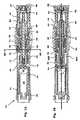
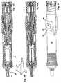
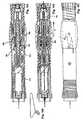
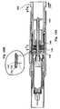
Fig. 1A-B are longitudinal cross-sectional view of a first embodiment injector according to the invention where the view 1B is taken 90° in relation to 1A,Fig. 2A is an exploded view of the embodiment shown inFig.1 ,Fig. 2B is a cross-sectional view taken along theline 2B-2B ofFig. 1A ,Figs. 3-12 A-D show the injector according toFig. 1 in different positions during the use of the injector where the B views are taken 90° in relation to the A views, where C is an side view corresponding to A and D shows a connection between a needle shield and a actuating means,Fig. 13 is a longitudinal cross-sectional view of a second embodiment injector according to the invention,Figs. 14-18 show the injector according toFig. 13 in different positions during the use of the injector,Fig 19 A-B show a variant of the injector ofFigs. 1-12 .- A first embodiment of the injector according to the invention shown in
Fig. 1 is generally denoted withreference numeral 10. In the following detailed description reference will be made to the front or forward end or direction which corresponds to the end of the device where an injection needle is arranged and thus the rear or rearward end is the opposite end of the device. - It comprises a generally tubular
main housing 12 open at the front (to the left in the figures, and rear ends. Adjacent the front end a generally tubularcontainer holding housing 14 is arranged. It is secured to the main housing byprotrusions 16 extending through recesses in the main housing. The rear part of the container holding housing is further provided with awall 18 having a centrally positioned through-hole. From the wall a generallytubular section 20 is extending rearwardly and arranged withthreads 22 on the inner surface adjacent its end. The outer surface at the end is arranged with longitudinally extending grooves or splines 24 around its circumference. At the front end of the container holding housing 14 a threadedneck portion 26 is attached, having an opening in the front direction, for attaching aneedle 28, as shown inFig. 3 . Inside the container holding housing acontainer 30 is arranged, containing the medicament to be injected into a patient. The rear part of the container is arranged with aslidable piston 32. Between the main housing and the container holding housing aneedle shield 34 is arranged slidably between a retracted state and an extended state, as will be explained below. Theneedle shield 34 is however fixed rotationally in that the outer surface of the container holding housing is arranged with longitudinally extendingridges 35,Fig. 2A , and that the inner surface of the needle shield is arranged with longitudinally extending grooves having corresponding dimensions as the ridges. The rear end of the needle shield is arranged with twotongues 36 A, B,Fig. 1B , each having a cut-outgroove 38, with a certain shape. Both the main housing and the needle shield are provided withwindows container holding housing 14 is preferably made of a clear material in order for the patient to be able to view the container and its content. - A threaded
drive rod 42 is in engagement with thethreads 22 of therear section 20 of the container holding housing, passes through thewall 18 and is in contact with thepiston 32 of the container. Preferably anabutment plate 44 is arranged between the piston and the drive rod where the abutment plate is arranged with a recess and the end of the piston is pointed and positioned in the recess so as to reduce the friction between them, as will be explained below. The opposite end of the drive rod is arranged with a stop means 43 in the form of a rim or the like, the function of which will be explained below. The length of the drive rod is also adjusted for the stroke of the piston in the medicament container. - A
nut 46, hereafter named lock nut, is further also arranged on the drive rod, so as to be slidable but rotationally fixed in relation to the drive rod by means oflongitudinal grooves 45 on thedrive rod 42 and corresponding tabs orprotrusions 47 on the inner surface of the lock nut,Fig. 2B . The outer surface of thelock nut 46 is arranged with longitudinally directed grooves or splines in the same manner as therear end 20 of thecontainer holding housing 14. These grooves or splines are arranged such that they may engage mating longitudinal grooves or splines arranged on the inner surface of asleeve 48, hereafter named lock sleeve, slidably arranged outside the rear section and the lock nut. Outside and surrounding thelock sleeve 48 is afurther sleeve 50, hereafter named dose actuating sleeve, arranged slidable and turnable within the main housing. The inner surface of the dose actuating sleeve is arranged withabutment ledges 52 to hold thelock sleeve 48 in a fixed longitudinal relation to the dose actuating sleeve but permitting turning of the dose actuating sleeve without turning the lock sleeve. The rear end of the needle shield is attached to the dose actuating sleeve byprotrusions 54,Figs. 2A and4B , arranged on forwardly directedtongues 56 of theactuating sleeve 50 fitting into therecesses 38 in the tongues of the needle shield. A spring is arranged between anabutment surface 58 arranged inside the dose actuating sleeve and aledge 60 arranged on the inner surface of the main housing. The rear end of the dose actuating sleeve is arranged with twotongues 61,Fig. 2 . - Along the drive rod 42 a dose adjusting means 62, hereafter named dose nut, is arranged. It comprises a first
inner section 64 of generally tubular shape where its front end is arranged with longitudinally extending grooves or splines 65 in the same manner as thelock nut 46. The first section merges into asecond section 66 havingthreads 67 on its inner surface in engagement with the threaded drive rod. The dose nut then continues into a third widertubular section 68 with an open end. The outer surface of the third section is arranged with symbols and/orindications 69 of the mode of operation of the device as well as dose quantities to be delivered, as will be explained below. These symbols and indications are visible through awindow 70 in the main housing. Aspring 71 is arranged between an end surface of thelock nut 46 and an interior ledge of thedose nut 62. Inside the third section a further generallytubular sleeve 72, hereafter named dose pusher, is arranged. The rear end of the dose pusher is arranged with rearwardly extendingtongues 75. The rear end of the main housing is arranged with anend wall 76 having openings (not shown) through which thetongues 75 of the dose pusher extend, thereby fixating the dose pusher rotationally with the main housing. - An
actuating spring 78 is arranged inside the threaded piston extending between an abutment surface inside the front end of the piston and theend wall 76 of the main housing. Aguide rod 80 is arranged inside the spring. On the outer surface of the rear end of the main housing are arrangedthreads 82, which cooperate with internal threads of adose setting knob 84 arranged at the rear end of the device, to the right in the figures. Aspring 86 is arranged between the inner surface of the dose setting knob and theend wall 76 of the main housing. The rear end surfaces of thetongues 75 of the dose pusher is in contact withwasher 87 arranged inside thedose setting knob 84 but rotationally fixed in relation to the dose setting knob. Opposite facing surfaces of the washer and the dose setting knob are arranged with ratchets or the like in order to create distinct positions of the dose setting knob. - Outside the main housing a
sleeve 88, hereafter named mode selector, is arranged slidably and turnable. The inner surface of the mode selector is arranged with two inwardly directed pins orprotrusions 90, where one is visible inFig. 4A . The protrusions extend through twocutouts 92,Fig. 3C , arranged on the main housing providing three distinct positions of the protrusions to be placed, each corresponding to a specific mode of function, such as LOCKED, UNLOCKED and INJECTION, as will be explained in detail below. The positions are preferably marked with suitable indications on the main housing for facilitating the proper use of the device. In that respect the mode selector is preferably made of a clear material. Theprotrusions 90 extend into correspondingrecesses 92,Fig. 2A , in thedose actuating sleeve 50 in order to manoeuvre the dose actuating sleeve as will be explained. - The device is intended to function as follows. The injector is received by the patient as shown in
Fig. 1 , with the needle shield in a retracted position held there by appropriate releasable holding means. Themode selector 88 is positioned with its protrusions in the UNLOCKED position,Fig. 3C . This facilitates for the patient to attach a needle by threading a needle, arranged inside aneedle cover 94, onto the threadedneck portion 26 of thecontainer holding housing 14,Fig. 3 . An inner end of the needle will thereby penetrate a membrane at the front end of the container, thereby establishing a passage between the needle and the interior of the container. It is also conceivable to omit the releasable holding means whereby the device is delivered with an extended needle shield. When the mode selector is placed in the UNLOCKED position the needle shield can be pushed inside the main housing because of the configuration of thegrooves 38 enabling theprotrusions 54 to slide between a front and a rear position in the groove, as indicated inFig. 3D . In this case the needle shield is pushed inside when a needle is attached. - The mode selector is then turned and pushed forward and to the LOCKED position,
Fig. 4C , whereby thedose actuating sleeve 50 is turned and moved forward by thespring 58 acting on thedose actuating sleeve 50 which in turn moves the needle shield forward. Theprotrusions 54 of the dose actuating sleeve are moved in thegrooves 38 to a position as shown inFig. 4D , in which position theprotrusions 54 engage withmating ledges 96 on the inner surface of the main housing, thereby locking the needle shield,Fig. 4B . This movement causes theneedle cover 94 to be pushed off the needle and theneedle shield 34 surrounds the needle in a locked position. - The next step,
Figs. 5-7 , is to prime the device, i.e. remove all possible air entrained inside the container. The patient thereby turns thedose setting knob 84 until the indication "prime" or any other suitable indication, is visible in thewindow 70,Fig. 5 . The turning of thedose setting knob 84 causes it to move a certain distance X in relation to themain housing 12. The force from thespring 71 between the nut and thedose nut 62 urges the dose nut upwards and because the dose setting knob is moved, the dose nut will rotate along thedrive rod 42 and move the distance X because thetongues 75 are in contact with the dose setting knob, thereby creating a distance X between the front end of thefirst section 64 of the dose nut and thelock nut 46Fig. 5A . The rotation of the dose nut is also enabled because themode selector 88 previously has been moved forward to the INJECTION position,Fig. 5C , and thereby the dose actuating sleeve and thelock sleeve 48, whereby the lock sleeve and its splines have been moved out of contact with thesplines 65 of thedose nut 62. However the splines of the lock sleeve are in engagement with thesplines 24 of thecontainer holding housing 14 and the splines of thenut 46. - In order to initiate priming,
Fig. 6A , themode selector 88 is turned anticlockwise somewhat in order for theprotrusions 54 to move out of contact with theledges 96 and pulled backwards in the direction of arrow I, whereby thedose actuating sleeve 50 also is pushed backwards due to theprotrusions 90 and theneedle shield 34 due to its connection with the dose actuating sleeve via thegroove 38 andprotrusions 54,Fig. 6D . This in turn moves thelock sleeve 48 backwards because its engagement with the dose actuating sleeve until the splines of the lock sleeve are brought out of engagement with the rotationally fixedsplines 24 of thecontainer holding housing 14. Thelock sleeve 48 is now free to rotate and because of the forwardly directed force of thedrive rod spring 78 the drive rod will start to rotate in relation to the fixed threads of thecontainer holding housing 22 in unison with thelock nut 46, thelock sleeve 48 and thedose nut 62. This rotation causes the advance of thedrive rod 42, the lock nut, which slides along the drive rod with itsprotrusions 47 in the longitudinal grooves of the drive rod, and the dose nut until the lock nut abuts the rear end of the dose holding housing and the front end of thefirst section 64 abuts thelock nut 46, thereby locking the drive rod from rotation,Fig. 7 . The rotation of the dose nut enables an indication to be shown in thewindow 70 that the priming is completed. - The device is now primed and when the
mode selector 88 is released it is pushed forward by thespring 58 whereby theprotrusions 90 are positioned in the LOCKED position in the cut-out of the main housing,Fig. 11C and the device is locked,Fig. 8 . Theneedle shield 14 is also locked in that theprotrusions 54 extending through therecesses 38 of the needle shield are in engagement withledges 96 arranged on the inside of themain housing 12,Fig. 8B . - In order to perform an injection the required dose has to be set, which is done by turning the mode selector to INJECTION whereby the
protrusions 54 of thedose actuating sleeve 50 are positioned as shown by dotted lines inFig. 10D . Thedose setting knob 84 is then turned until the required dose is visible in thewindow 70,Fig. 9 . As with the priming, the turning of the setting knob enables thedose nut 62 to rotate along thedrive rod 42 and move a certain distance Y from thelock nut 46. Again thelock sleeve 48 is in a position such that it locks the nut and is at the same time prevented from rotating because of the engagement with thesplines 24 of thecontainer holding housing 14,Fig. 9 . The device is now pressed against the injection site whereby the needle penetrates the skin. At the same time theneedle shield 34 is pushed into the device. Because of the fixed connection between thegroove 38 and theprotrusions 54, in that the protrusions move to the position shown with unbroken lines inFig. 10D , the movement of the needle shield causes thedose actuator sleeve 50 to move backwards and thereby also thelock sleeve 48,Fig. 10 . When the lock sleeve has moved backwards a certain distance the engagement between the splines of the lock sleeve and thesplines 24 of thecontainer holding housing 14 is released and the lock sleeve and thus thedrive rod 42 is free to rotate and to be moved forward because of the threaded engagement with thethreads 22 of the container holding sleeve. Again the rotation continues until thelock nut 46 comes in contact the rear end of the container holding housing and thedose nut 62 comes in contact with the lock nut,Fig. 11 , whereby the injection is completed. And again the rotation of the dose nut provides for an indication in thewindow 70 that the injection is completed. - The needle may now be withdrawn from the patient, whereby the
needle shield 34, thedose actuating sleeve 50, thelock sleeve 48 and themode selector 88 are pushed forwards by the force of thespring 58 until theprotrusions 90 enter the LOCKED position. The needle shield is now locked in order to prevent accidental needle sticks. During the injection, the dose adjusting means 62 moved forward the distance Y in relation to thedose pusher 72. Thus, upon completion of the injection this distance Y is present between the bottom surface of thethird section 68 and the front end surface of the dose pusher,Fig. 11A . When now the dose actuating sleeve and the lock sleeve are moved forward the dose nut is free to rotate along the drive rod until the bottom surface of the third section again abuts the front end surface of the dose pusher. This means that the previously set dose becomes the "default" dose for the subsequent injection as the mode selector is positioned in the INJECTION position. Thus, a patient does not have to adjust the dose for each injection unless a different dose is required. - If the last dose is smaller than the preset dose or for that matter a dose the patient is trying to set, this cannot be performed due to the stop means 43 at the end of the drive rod. The stop means prevents the dose nut from rotating any further, whereby the dose quantity that can be delivered is shown in the
window 70 when the dose nut has been turned until it abuts the stop means, either when automatically adjusted as described above, or when a patient tries to set a certain dose, thus ensuring that the set dose cannot be larger than the remaining quantity and the actual dose that can be delivered is displayed in the window. However, it is possible to rotate the dose setting knob further, but this action will not affect the dose nut, that thus still will show the dose that can be delivered. It is of course still possible to set a smaller dose than the last preset remaining dose in the container. Also in order to ensure this the length of the drive rod is adjusted to correspond to the stroke of the medicament container. - For a subsequent dose, or for storage, it is necessary and preferable respectively that the used needle is removed and possibly replaced. In order to remove the needle the mode selector is set to UNLOCKED whereby the needle shield can be pushed inside the device as described above in connection with
Fig. 3D . The needle cover is pushed into the needle shield and the needle shield is retracted and acts as a guide for the needle cover for obtaining the right position and angle in relation to the needle, thus assuring that the needle does not accidentally penetrate the needle cover. The needle can then be unscrewed from the threaded neck portion. The device can now be stored or be prepared by attaching a new needle to the device, in the same manner as described above. In this respect, and as indicated above, thegrooves 38 of the needle shield may have a different design or configuration. - An injector not according to the invention is shown in
Figs. 19 A, B comprising a main housing 12' a dose setting knob 84', a window 40' for viewing the container and its content and a window 70' for displaying the set dose or that a dose has been delivered. The interior mechanism is otherwise very similar to the previous embodiment. With this variant the mode selector 88' is placed in the front end of the device. As with the previous selector it can be positioned in different modes of operation (LOCKED, UNLOCKED and INJECTION) enabling the same functions as above and also slidable in the longitudinal direction for attaching, replacing or removing a needle, priming and the like. With this variant the selector also acts as the needle shield so that when placed in INJECTION mode the mode selector/needle shield is pressed against the injection site and thus pressed into the device, thereby actuating the injection in the same way as described above. This variant has the advantage that the mode selector has the dual function of needle cover, thus reducing the number of components of the device. It is also been proven logical for a user to have the mode selector, by which the needle can be attached, the dose primed and the injection initiated, at a location where the needle actually is situated. - A second embodiment will now be described in connection with drawings 13 to 19.
- The second embodiment comprises a
needle shield 112 of a generally tubular shape and open at both ends. InFig. 13 the needle shield is held in a retracted position against the force of a spring not shown. The needle shield surrounds a generally tubularcontainer holding housing 116. Inside the container housing acontainer 118 is arranged, which contains the medicament to be delivered. The front end of the container housing is arranged with a threadedneck 120 onto which aneedle 121 can be threaded. In doing so, the rear end of the needle penetrates an elastic membrane arranged at the end of the container, thereby providing access to the medicament through the needle. Aneedle cover 124 is further arranged around the needle. The rear end of the medicament container is provided with apiston 126 slidable within the container. - The
container housing 116 is attached to amain injector housing 128 of a generally tubular elongated shape. Inside the main housing awall 130 is arranged. The wall is arranged with a centrally located passage, through which ashaft 132. The shaft is provided with threads. The passage and the shaft are arranged such that the shaft may slide through the passage but is prevented from rotating. The front end of the shaft, to the left in the figures, is abutting the piston of the container. Adose actuation spring 134 is arranged between the piston and the wall and is surrounding the shaft. On the right side of the wall, as seen in the figures, afirst nut 136 is threaded onto the threaded shaft and in sliding contact with thewall 130. Friction-reducingmeans 138 are arranged between the nut and the wall, such as low-friction surfaces or ball bearings. Asecond nut 140 is also threaded onto the shaft and acompression 142 is arranged between the two nuts in respective recesses. The outer surfaces of the nuts are arranged with a plurality ofgrooves 144 directed in the longitudinal direction of the injector. These grooves cooperate with protrusions or splines 146 on the inside of the inner end of the needle shield in a manner which will be explained below. - Dose adjusting means 148 is arranged at the right end of the injector. It comprises a generally
tubular body 150 extending into the main body. The inner end of the dose body is arranged with awall 152, which wall is provided with a passage for allowing the threadedshaft 132 to pass through. Thespring 114 of theneedle shield 112 is resting against aledge 154 of the dose body. The outer surface of the dose body and the inner surface of the main body are provided withcorresponding threads 156 in order to displace thedose body 150 axially in relation to themain body 128 for adjusting the dose quantity. The right-most end of the dose body is provided with agripping part 158 for rotation of the dose body in relation to the main body. The outer end of the shaft is arranged with amovement limiting washer 160. The injector is further provided with asafety button 162 arranged on the main body and designed with a longitudinally extending protrusion, which protrusion, when pressing the button into the main body, co-acts with therecesses 144 of thenuts - The injector according to the invention is intended to work as follows. When a patient receives a new injector, it is pre-loaded with a
medicament container 118. Thenuts shaft 132 so that the end of the shaft is abutting thepiston 126 of the container. Thereby theactuating spring 134 is fully compressed. The user thus do not need to pre-tension the actuating spring before use. Theneedle shield 112 is further brought to its retracted state. When the patient is to inject a dose he picks a newsterile needle 121, often complete with asafety cap 124, and threads it onto the threadedneck 120 of thecontainer holder 116. The needle shield is then released and the needle shield spring urges the needle shield forward, to the left in the figures. This movement may causes the end of the needle shield to push off the needle cover,Fig. 14 , due to the design of the needle cover. The next step is to set the dose. Thedose body 150 is then turned by thegripping part 158 to a certain dose quantity position,Fig. 15 . In order for the patient to adjust the dose body, the injector may be provided with display means indicating the adjusted dose. This may for example be done by a scale marked on the main body adjacent the gripping part and an arrow or mark on the gripping part. The gripping part may then be turned until the arrow is opposite the desired dose quantity. - The turning of the gripping part and thus the dose body causes the dose body to move axially in relation to the main body due to the threads between the two,
arrow 170,Fig. 15 , a certain distancea. Due to thespring 142 or torsion between the nuts 136, 140 thesecond nut 140 is threaded along the shaft the same distancea as the dose body has moved. The force of the spring reduces the play between the parts, enhancing the precision of the device. Thefirst nut 136 is prevented from rotating due to theprotrusion 172 on theneedle shield 112, which is in contact with the grooves on the periphery of the nut,Fig. 15a . The injector is now ready for injection. - This is done by pushing the outer end of the
needle shield 112 against the injection site, pushes the needle shield into the injector against the spring force, thereby penetrating the skin with the needle,Fig. 16 . The force from the needle shield aids in stretching the skin part to be penetrated. The pushing of the needle shield into the main body causes theprotrusion 172 of theneedle shield 112 to come out of contact with thegrooves 144 of the first nut,Fig. 16b . Because thefirst nut 136 now is free to rotate and because of the force from the actuating spring and the low friction between thefirst nut 136 and thewall 130 because of the low-friction means 138, the first nut will rotate. The rotation causes the shaft to be moved axially to the left in the figures due to the threads between thefirst nut 136 and theshaft 132. The second nut is now locked by theprotrusion 172 of theneedle cover 112,Fig. 16b . The axial movement of the shaft pushes thepiston 126 into the container so that medicament is injected into the patient through theneedle 121. The axial movement continues until thesecond nut 140 comes in contact with thefirst nut 136 under compression of thespring 142 between the nuts where thesecond nut 140 is prevented from rotating by theprotrusion 172 of the needle shield engaging the grooves of the second nut,Fig. 17 . It is to be noted that thespring 142 between the two nuts is much weaker than the force from the actuation spring. - The injection is now completed and the needle is withdrawn from the patient. The
spring 114 of the needle shield then pushes needle shield out of the injector whereby thesecond nut 140 again is released and is threaded along the shaft until it comes in contact with thewall 152 of thedose body 50. The injector is thus again ready for use,Fig. 18 . As can be understood from the foregoing and from the figures the subsequent dose will be of the same quantity if no adjustment is made of the dose body. If the same dose quantity is to be delivered repeatedly the patient does not have to make any adjustments whatsoever. It is to be noted that the increments of the dose size and precision of the of the injector is very much determined by the pitch of the threads and number of grooves. - In order not to activate the injector because the needle shield is pushed back, the patient presses a mode state button/ means 162. Thereby the protrusion of the button engages the grooves of the first nut and prevents it from rotating even if the protrusion of the needle shield comes out of contact with the grooves of the first nut. When the patient is to take a subsequent dose the needle has to be replaced with a new, sterile, needle. He therefore pushes the needle shield back to be able to replace the needle.
- When the container is nearly empty, the locking
washer 160 is close to thedose body wall 152 it limits how much the shaft is able to move in the subsequent injection. It is then impossible to adjust the dose body further than the remaining dose because adjustment of the dose body, ie axial displacement, will cause the wall of the dose body to come in contact with the locking washer. This indicates to the patient that the medicament container is almost empty and/or may not be able to deliver the required dose of medicament. It is conceivable that the end of doses locks the needle shield and the safety button so that the injector can safely be discarded. - In some instances before the first injection the injector has to be primed, ie to empty the container of possible air trapped inside. Then the second step after connecting a needle is to adjust the dose body to a priming position, thereby moving the dose body and the second nut a certain distance axially, in the same manner as described in connection with injections. As also described earlier, when the needle shield is nearly fully pushed into the injector, the protrusion of the needle shield is moved out of contact with the grooves of the first nut. It is thereby free to rotate and to be threaded along the shaft due to the force of the compression spring. The shaft is thus moved axially, pushing the piston further into the container whereby entrapped air and medicament is ejected through the needle, until the second nut comes into contact again with the first nut. The needle shield is now released and returns to its extended state. This causes the second nut to be released whereby it is threaded along the shaft until it comes in contact with the wall of the dose body.
- The needle shield may also be provided with locking means to lock it in the extended position in order to minimize the risk of accidental needle-sticks. The mode selector means may further be provided with release means for releasing the locking of the needle shield for an injection or for replacing the needle. It may also be provided with three different settings; lock, where the injector and needle shield is locked; load, where it is possible to change needle without the risk of firing the injector; and dose, where the injector is ready for injection as described above. In this context the needle shield may be in two parts, a lower and an upper part, and that the lower part is locked in the extended state after injection and withdrawal of the injector, and that it requires a twist or turning action in order to be released and to co-act with the upper part as described above.
- It is to be understood that the invention as described above and shown in the drawings is a non-limiting example and that the invention is defined by the patent claims. Thus, several parts of the described injector may be replaced with other part with the same or similar function as will be readily appreciated by the skilled person.
Claims (4)
- Injection device comprising:-) a tubular elongated injector housing to which a container housing (116) is attached, the container housing having a container (118) with medicament;-) a wall (130) arranged inside the injector housing and provided with a central passage;-) means (120) for connecting a needle (121) to the container;-) actuating means capable of injecting a dose of medicament upon activation, said actuating means comprising a threaded plunger rod (132) passing through said passage such that the plunger rod may slide through the passage but is prevented from rotating relative to the injector housing, a first pre-tensioned actuating spring (134) surrounding said plunger rod and capable of pushing said plunger rod into said container for expelling the dose of medicament through said needle, and a threaded lock nut (136) surrounding said plunger rod and in sliding contact with said wall, said threaded lock nut being capable of locking the movement of said plunger rod into said container when prevented from rotating relative to said plunger rod;-) means capable of setting a dose to be injected, comprising a manually operable dose setting knob (150) in threaded connection with a rear end of the injector housing, a threaded dose setting nut (140) in threaded connection with the plunger rod, a second spring (142) arranged between the lock nut and the dose setting nut the dose setting nut surrounding said plunger rod such that rotation of said dose setting knob allows said second spring to cause a displacement of said dose setting nut a certain distance corresponding to a certain dose of medicament;-) activating means capable of activating said actuating means and comprising a needle shield (112) surrounding said container housing and slidable between an extended and a retracted position in relation to said injector housing, such that upon penetration of the needle into a patient, when the needle shield is moved or pushed towards its retracted position, it acts on said lock nut thereby allowing relative rotation of the lock nut relative to said plunger rod such that said plunger rod is released for injecting the set dose, the injection of said set dose being completed when said dose setting nut comes into contact with said lock nut.
- Injection device comprising:-) a tubular elongated injector housing to which a container housing (14) is attached, the container housing having a container (30) with medicament;-) means (26) for connecting a needle (28) to the container;-) actuating means capable of injecting a dose of medicament upon activation, said actuating means comprising a threaded plunger rod (42) in threaded connection with said container housing, a first pre-tensioned actuating spring (78) arranged inside said plunger rod and capable of pushing said plunger rod into said container for expelling the dose of medicament through said needle, a lock nut (46) surrounding said plunger rod, said lock nut being slidable but rotationally fixed relative to said plunger rod, and a lock sleeve (48) slidably arranged at the rear section of said container housing and around the lock nut;-) means capable of setting a dose to be injected, comprising a manually operable dose setting knob (84) in threaded connection with a rear end of the injector housing, a threaded dose setting nut (62) in threaded connection with the plunger rod, a second spring (71) arranged between the lock nut and the dose setting nut, the dose setting nut surrounding said plunger rod such that rotation of said dose setting knob allows said second spring to cause a displacement of said dose setting nut a certain distance corresponding to a certain dose of medicament, whereby, when said dose setting knob is rotated for setting a dose said lock sleeve is engaged with the rear section of said container housing and to said lock nut thereby locking said lock nut and said drive rod against rotation;-) activating means capable of activating said actuating means and comprising a dose actuating sleeve (50) arranged around the lock sleeve (48) and a needle shield (34) surrounding said container housing and connected to said actuating sleeve, said needle shield being slidable between an extended and a retracted position in relation to said injector housing, such that upon penetration of the needle into a patient, when the needle shield is moved or pushed towards its retracted position, it acts on said dose actuating sleeve and by means thereof on said lock sleeve thereby releasing said plunger rod such that it can rotate for injecting the set dose, the injection of said set dose being completed when said dose setting nut comes into contact with said lock nut.
- Injection device according to claim 1 or 2, wherein the dose setting means is designed and arranged such that a set dose will become the subsequent dose in the dose setting means is not adjusted, by e.g. the user.
- Injection device according to any of claims 1-3, wherein the plunger rod is arranged with a stop means (43, 160, 152) for preventing a set dose from exceeding a dose remaining in the medicament container.
Applications Claiming Priority (3)
| Application Number | Priority Date | Filing Date | Title |
|---|---|---|---|
| US41281502P | 2002-09-24 | 2002-09-24 | |
| US412815P | 2002-09-24 | ||
| PCT/SE2003/001483WO2004028598A1 (en) | 2002-09-24 | 2003-09-24 | Injecting device |
Publications (2)
| Publication Number | Publication Date |
|---|---|
| EP1542744A1 EP1542744A1 (en) | 2005-06-22 |
| EP1542744B1true EP1542744B1 (en) | 2009-06-24 |
Family
ID=32043192
Family Applications (1)
| Application Number | Title | Priority Date | Filing Date |
|---|---|---|---|
| EP03798634AExpired - LifetimeEP1542744B1 (en) | 2002-09-24 | 2003-09-24 | Injecting device |
Country Status (10)
| Country | Link |
|---|---|
| US (1) | US7112187B2 (en) |
| EP (1) | EP1542744B1 (en) |
| JP (1) | JP4448448B2 (en) |
| AT (1) | ATE434455T1 (en) |
| AU (1) | AU2003265179B2 (en) |
| CA (1) | CA2500195C (en) |
| DE (1) | DE60328109D1 (en) |
| DK (1) | DK1542744T3 (en) |
| ES (1) | ES2327731T3 (en) |
| WO (1) | WO2004028598A1 (en) |
Cited By (4)
| Publication number | Priority date | Publication date | Assignee | Title |
|---|---|---|---|---|
| WO2011043712A1 (en) | 2009-10-08 | 2011-04-14 | Shl Group Ab | Metered liquid droplet inhaler |
| US9415165B2 (en) | 2009-10-16 | 2016-08-16 | Owen Mumford Limited | Injector apparatus having a clutch to inhibit forward movement of the plunger |
| WO2022128520A1 (en)* | 2020-12-16 | 2022-06-23 | Shl Medical Ag | A sub-assembly for a medicament delivery device cassette unit |
| EP4138961B1 (en)* | 2020-04-23 | 2024-06-05 | Novo Nordisk A/S | Activatable drug delviery device with safety assembly |
Families Citing this family (215)
| Publication number | Priority date | Publication date | Assignee | Title |
|---|---|---|---|---|
| US6663602B2 (en) | 2000-06-16 | 2003-12-16 | Novo Nordisk A/S | Injection device |
| US6899699B2 (en) | 2001-01-05 | 2005-05-31 | Novo Nordisk A/S | Automatic injection device with reset feature |
| US20040098010A1 (en)* | 2001-10-22 | 2004-05-20 | Glenn Davison | Confuser crown skin pricker |
| WO2003068290A2 (en) | 2002-02-11 | 2003-08-21 | Antares Pharma, Inc. | Intradermal injector |
| US11083841B2 (en) | 2002-08-09 | 2021-08-10 | Fenwal, Inc. | Needle protector, needle assembly and fluid processing set including the same |
| US9486581B2 (en)* | 2002-09-11 | 2016-11-08 | Becton, Dickinson And Company | Injector device with force lock-out and injection rate limiting mechanisms |
| DE10320225A1 (en)* | 2003-05-05 | 2004-12-02 | L + N Plast-Vertriebs Gmbh | Reusable actuator for a sterile syringe |
| DE10339794A1 (en)* | 2003-08-28 | 2005-04-07 | Tecpharma Licensing Ag | Administering device with a protective cap removal device and a needle protection sleeve blocking device |
| IL157981A (en) | 2003-09-17 | 2014-01-30 | Elcam Medical Agricultural Cooperative Ass Ltd | Auto-injector |
| DE10348185A1 (en)* | 2003-10-16 | 2005-05-19 | Tecpharma Licensing Ag | Injection device for administering fluid product e.g. insulin, comprising injection needle and needle cover arranged on holder or on casing so that it can shift and generally surrounds injection needle in advanced position |
| DE20317377U1 (en)* | 2003-11-03 | 2005-03-17 | B D Medico S A R L | injection device |
| DE10351597A1 (en)* | 2003-11-05 | 2005-06-16 | Tecpharma Licensing Ag | Device and autoinjector for administration of an injectable product, useful in drug administration, e.g. for intravenous injection, comprises a housing, a product reservoir, piston, priming mechanism and metering element |
| CH696421A5 (en) | 2003-12-18 | 2007-06-15 | Tecpharma Licensing Ag | Autoinjector with arresting the drug container. |
| WO2005069831A2 (en)* | 2004-01-12 | 2005-08-04 | Iscience Surgical Corporation | Injector for viscous materials |
| GB0409354D0 (en)* | 2004-04-27 | 2004-06-02 | Owen Mumford Ltd | Removal of needles |
| GB2414404B (en) | 2004-05-28 | 2009-06-03 | Cilag Ag Int | Injection device |
| GB2414406B (en) | 2004-05-28 | 2009-03-18 | Cilag Ag Int | Injection device |
| GB2414401B (en) | 2004-05-28 | 2009-06-17 | Cilag Ag Int | Injection device |
| GB2414409B (en) | 2004-05-28 | 2009-11-18 | Cilag Ag Int | Injection device |
| GB2414405B (en) | 2004-05-28 | 2009-01-14 | Cilag Ag Int | Injection device |
| GB2414402B (en) | 2004-05-28 | 2009-04-22 | Cilag Ag Int | Injection device |
| GB2414400B (en) | 2004-05-28 | 2009-01-14 | Cilag Ag Int | Injection device |
| GB2414403B (en) | 2004-05-28 | 2009-01-07 | Cilag Ag Int | Injection device |
| GB2414775B (en) | 2004-05-28 | 2008-05-21 | Cilag Ag Int | Releasable coupling and injection device |
| GB2414399B (en) | 2004-05-28 | 2008-12-31 | Cilag Ag Int | Injection device |
| GB0414054D0 (en) | 2004-06-23 | 2004-07-28 | Owen Mumford Ltd | Improvements relating to automatic injection devices |
| US7449012B2 (en)* | 2004-08-06 | 2008-11-11 | Meridian Medical Technologies, Inc. | Automatic injector |
| US7740618B2 (en) | 2004-10-14 | 2010-06-22 | Novo Nordisk A/S | Syringe device |
| ATE444090T1 (en) | 2004-10-21 | 2009-10-15 | Novo Nordisk As | SELECTION MECHANISM FOR A ROTARY PIN |
| KR101278123B1 (en) | 2004-10-21 | 2013-06-24 | 노보 노르디스크 에이/에스 | Injection device with torsion spring and rotatable display |
| ES2557778T3 (en) | 2004-11-24 | 2016-01-28 | Group Ab Shl | Injection device |
| JP4934051B2 (en)* | 2004-11-24 | 2012-05-16 | エスホーエル メディカル アクチボラゲット | Injection device |
| DE102004063644A1 (en)* | 2004-12-31 | 2006-07-20 | Tecpharma Licensing Ag | Device for the dosed administration of a fluid product with torsion spring drive |
| HUE042286T2 (en) | 2005-01-24 | 2019-06-28 | Antares Pharma Inc | Needle-filled pre-filled syringe |
| DE102005008280B3 (en)* | 2005-02-23 | 2006-07-13 | Tecpharma Licensing Ag | Medicine administering device has medicine transporting elements and a dosing device that is used with a display drum and an activation element to permit the accurate administration of correct medicine amounts |
| WO2006089768A1 (en)* | 2005-02-28 | 2006-08-31 | Novo Nordisk A/S | A dose setting mechanism for an injection device |
| ATE417642T1 (en) | 2005-02-28 | 2009-01-15 | Novo Nordisk As | DOSE SETTING MECHANISM FOR AN INJECTION DEVICE WHICH CAN PRESET A MAXIMUM DOSE |
| DE502005005948D1 (en)* | 2005-03-24 | 2008-12-24 | Disetronic Licensing Ag | Device for the dosed administration of a fluid product |
| EP1704883B1 (en)* | 2005-03-24 | 2008-11-12 | Disetronic Licensing AG | Device for the dosed administration of a fluid product |
| GB2424835B (en) | 2005-04-06 | 2010-06-09 | Cilag Ag Int | Injection device (modified trigger) |
| GB2424838B (en) | 2005-04-06 | 2011-02-23 | Cilag Ag Int | Injection device (adaptable drive) |
| GB2424836B (en) | 2005-04-06 | 2010-09-22 | Cilag Ag Int | Injection device (bayonet cap removal) |
| GB2427826B (en) | 2005-04-06 | 2010-08-25 | Cilag Ag Int | Injection device comprising a locking mechanism associated with integrally formed biasing means |
| GB2425062B (en) | 2005-04-06 | 2010-07-21 | Cilag Ag Int | Injection device |
| US20090043264A1 (en) | 2005-04-24 | 2009-02-12 | Novo Nordisk A/S | Injection Device |
| DE102005023823B4 (en)† | 2005-05-24 | 2022-11-17 | Tecpharma Licensing Ag | Dosing device for an injection device and injection device with such a dosing device |
| US9011386B2 (en) | 2005-06-01 | 2015-04-21 | Shl Group Ab | Device for delivering medicament |
| EP1728529B2 (en)* | 2005-06-01 | 2016-07-27 | SHL Group AB | Device for delivering medicament |
| PL1909871T5 (en) | 2005-07-27 | 2014-05-30 | Novo Nordisk As | Injection device with dose limiting mechanism and additional safety mechanism |
| US8920383B2 (en) | 2005-07-27 | 2014-12-30 | Novo Nordisk A/S | Dose mechanism for an injection device for limiting a dose setting corresponding to the amount of medicament left |
| PL1759729T3 (en) | 2005-08-30 | 2010-09-30 | Cilag Gmbh Int | Needle assembly for a prefilled syringe system |
| US20110098656A1 (en) | 2005-09-27 | 2011-04-28 | Burnell Rosie L | Auto-injection device with needle protecting cap having outer and inner sleeves |
| GB0524604D0 (en)* | 2005-12-02 | 2006-01-11 | Owen Mumford Ltd | Injection method and apparatus |
| GB2434103B (en) | 2006-01-12 | 2009-11-25 | Owen Mumford Ltd | Lancet firing device |
| US20070173770A1 (en) | 2006-01-23 | 2007-07-26 | The Medical House Plc | Injection device |
| GB0601309D0 (en) | 2006-01-23 | 2006-03-01 | Medical House The Plc | Injection device |
| WO2007099044A1 (en)* | 2006-03-03 | 2007-09-07 | Shl Medical Ab | Medical device with orientation sensitive priming mechanism |
| WO2007131013A1 (en) | 2006-05-03 | 2007-11-15 | Antares Pharma, Inc. | Two-stage reconstituting injector |
| WO2007131025A1 (en)* | 2006-05-03 | 2007-11-15 | Antares Pharma, Inc. | Injector with adjustable dosing |
| JP5253387B2 (en) | 2006-05-18 | 2013-07-31 | ノボ・ノルデイスク・エー/エス | Injection device with mode locking means |
| CA2653401A1 (en) | 2006-05-29 | 2007-12-06 | Novo Nordisk A/S | Mechanism for injection device |
| GB2438593B (en) | 2006-06-01 | 2011-03-30 | Cilag Gmbh Int | Injection device (cap removal feature) |
| GB2438590B (en) | 2006-06-01 | 2011-02-09 | Cilag Gmbh Int | Injection device |
| GB2438591B (en) | 2006-06-01 | 2011-07-13 | Cilag Gmbh Int | Injection device |
| KR101396797B1 (en) | 2006-06-30 | 2014-05-26 | 애브비 바이오테크놀로지 리미티드 | Automatic injection device |
| DE102007001432A1 (en)* | 2006-08-14 | 2008-02-21 | Tecpharma Licensing Ag | Blocking unit for dosing mechanism of injection device, has retaining unit acting together with dosing mechanism or dosing unit such that adjusting movement of mechanism or dosing unit in starting position of blocking unit is prevented |
| DE102006038101A1 (en)* | 2006-08-14 | 2008-02-21 | Tecpharma Licensing Ag | Injection device with jaw safety |
| DE102006038123C5 (en)* | 2006-08-14 | 2012-05-03 | Tecpharma Licensing Ag | Injection device with mechanical lock |
| DE102006038103B4 (en)* | 2006-08-14 | 2017-02-23 | Tecpharma Licensing Ag | Injection device with variable thread guide |
| HUE060243T2 (en)* | 2006-09-15 | 2023-02-28 | Ypsomed Ag | Injection device comprising an improved delivery element |
| US8052655B2 (en) | 2006-09-29 | 2011-11-08 | Novo Nordisk A/S | Injection device with electronic detecting means |
| ES2365931T3 (en)* | 2006-12-13 | 2011-10-13 | Shl Group Ab | AUTOMATIC INJECTOR |
| EP2109474B2 (en) | 2007-02-05 | 2019-01-30 | Novo Nordisk A/S | Injection button |
| US20080228147A1 (en) | 2007-03-15 | 2008-09-18 | Bristol-Myers Squibb Company | Injector for use with pre-filled syringes and method of assembly |
| USD612487S1 (en) | 2007-03-15 | 2010-03-23 | Bristol-Myers Squibb Co. | Injector |
| BRPI0809265A2 (en)* | 2007-03-23 | 2014-10-07 | Novo Nordisk As | INJECTION DEVICE INCLUDING A TIGHTENING NUT |
| DE102007016811A1 (en) | 2007-04-05 | 2008-10-09 | Tecpharma Licensing Ag | Device for administering a fluid substance from a multi-chamber ampoule |
| DE102007030327A1 (en)* | 2007-06-29 | 2009-01-02 | Tecpharma Licensing Ag | Injection device with a spring for a needle protection sleeve |
| US8460245B2 (en)* | 2007-07-19 | 2013-06-11 | Shl Group Ab | Device for delivering a medicament |
| US9108006B2 (en) | 2007-08-17 | 2015-08-18 | Novo Nordisk A/S | Medical device with value sensor |
| US8038649B2 (en)* | 2007-09-18 | 2011-10-18 | Shl Group Ab | Automatic injection device with needle insertion |
| BRPI0817907B8 (en) | 2007-10-02 | 2021-06-22 | Lamodel Ltd | apparatus for administering a substance to an individual |
| CA2707820A1 (en) | 2007-12-31 | 2009-07-09 | Novo Nordisk A/S | Electronically monitored injection device |
| US8992484B2 (en)* | 2008-01-23 | 2015-03-31 | Novo Nordisk A/S | Device for injecting apportioned doses of liquid drug |
| CA2711653C (en)* | 2008-01-23 | 2016-07-05 | Novo Nordisk A/S | Device for injecting apportioned doses of liquid drug |
| WO2009100549A1 (en)* | 2008-02-11 | 2009-08-20 | Tecpharma Licensing Ag | Administering apparatus comprising a holding device |
| WO2009120960A2 (en)* | 2008-03-27 | 2009-10-01 | Iscience Interventional Corporation | Microliter injector |
| GB2461086B (en) | 2008-06-19 | 2012-12-05 | Cilag Gmbh Int | Injection device |
| GB2461085B (en) | 2008-06-19 | 2012-08-29 | Cilag Gmbh Int | Injection device |
| GB2461087B (en) | 2008-06-19 | 2012-09-26 | Cilag Gmbh Int | Injection device |
| GB2461084B (en) | 2008-06-19 | 2012-09-26 | Cilag Gmbh Int | Fluid transfer assembly |
| GB2461089B (en) | 2008-06-19 | 2012-09-19 | Cilag Gmbh Int | Injection device |
| US8376993B2 (en) | 2008-08-05 | 2013-02-19 | Antares Pharma, Inc. | Multiple dosage injector |
| GB2463034B (en)* | 2008-08-28 | 2012-11-07 | Owen Mumford Ltd | Autoinjection devices |
| GB2465390A (en) | 2008-11-17 | 2010-05-19 | Owen Mumford Ltd | Syringe needle cover remover |
| US9089652B2 (en) | 2008-12-12 | 2015-07-28 | Sanofi-Aventis Deutschland Gmbh | Drive mechanism for a medication delivery device and medication delivery device |
| KR20110099031A (en) | 2008-12-12 | 2011-09-05 | 사노피-아벤티스 도이칠란트 게엠베하 | Resettable drive mechanism and drug release device for drug release device |
| EP2196232A1 (en) | 2008-12-12 | 2010-06-16 | Sanofi-Aventis Deutschland GmbH | Drive mechanism for a medication delivery device and medication delivery device |
| EP2196233A1 (en) | 2008-12-12 | 2010-06-16 | Sanofi-Aventis Deutschland GmbH | Resettable drive mechanism for a medication delivery device and medication delivery device |
| GB0900930D0 (en) | 2009-01-20 | 2009-03-04 | Future Injection Technologies Ltd | Injection device |
| JP5732039B2 (en) | 2009-03-20 | 2015-06-10 | アンタレス・ファーマ・インコーポレーテッド | Hazardous drug injection system |
| WO2010127146A1 (en) | 2009-04-29 | 2010-11-04 | Abbott Biotechnology Ltd | Automatic injection device |
| US9238106B2 (en)* | 2009-06-01 | 2016-01-19 | Sanofi-Aventis Deutschland Gmbh | Dose setting mechanism for priming a drug delivery device |
| TWI519330B (en)* | 2009-06-02 | 2016-02-01 | 賽諾菲阿凡提斯德意志有限公司 | Medicated module with user selection |
| CA2772686C (en)* | 2009-09-23 | 2018-01-02 | Sanofi-Aventis Deutschland Gmbh | Assembly and indicator for a drug delivery device |
| WO2011039212A1 (en) | 2009-09-30 | 2011-04-07 | Sanofi-Aventis Deutschland Gmbh | Drug delivery device |
| WO2011039213A2 (en)* | 2009-09-30 | 2011-04-07 | Sanofi-Aventis Deutschland Gmbh | An assembly of a drug delivery device |
| JP5756469B2 (en) | 2009-09-30 | 2015-07-29 | サノフィ−アベンティス・ドイチュラント・ゲゼルシャフト・ミット・ベシュレンクテル・ハフツング | Drug delivery device |
| JP5701889B2 (en) | 2009-10-08 | 2015-04-15 | エス・ホー・エル・グループ・アクチボラゲットShl Group Ab | Drug supply device |
| WO2011047298A2 (en) | 2009-10-16 | 2011-04-21 | Centocor Ortho Biotech Inc. | Palm activated drug delivery device |
| US9233213B2 (en) | 2009-10-16 | 2016-01-12 | Janssen Biotech, Inc. | Palm activated drug delivery device |
| EP2490734B1 (en)* | 2009-10-23 | 2020-03-25 | Medicom Innovation Partner a/s | Auto injector with automatic needle shielding |
| PL215310B1 (en)* | 2009-10-30 | 2013-11-29 | Kappa Medilab Spolka Z Ograniczona Odpowiedzialnoscia | Automatic applicator, especially for insulin |
| TWI415645B (en)* | 2009-11-10 | 2013-11-21 | Shl Group Ab | Medicament delivery device |
| TWI569844B (en)* | 2009-11-10 | 2017-02-11 | 瑞健集團股份有限公司 | Medicament delivery device |
| ES2749395T3 (en) | 2009-11-20 | 2020-03-20 | Becton Dickinson Co | Injection device without the need for a gear |
| ES2909887T3 (en)* | 2009-12-01 | 2022-05-10 | Becton Dickinson Co | Injection pen with automatic return and last dose control |
| EP2512558A4 (en) | 2009-12-15 | 2014-08-13 | Abbvie Biotechnology Ltd | IMPROVED TRIP PUSHER FOR AUTOMATIC INJECTION DEVICE |
| CN102869399B (en)* | 2010-03-09 | 2015-06-24 | Shl集团有限责任公司 | Medicament delivery device |
| EP2583708B1 (en)* | 2010-03-31 | 2023-02-22 | SHL Medical AG | Medicament delivery device comprising feedback signalling means |
| JP5722992B2 (en)* | 2010-04-07 | 2015-05-27 | エス・ホー・エル・グループ・アクチボラゲットShl Group Ab | Drug delivery device |
| NZ702172A (en) | 2010-04-21 | 2016-03-31 | Abbvie Biotechnology Ltd | Wearable automatic injection device for controlled delivery of therapeutic agents |
| JP6165055B2 (en)* | 2010-06-28 | 2017-07-19 | サノフィ−アベンティス・ドイチュラント・ゲゼルシャフト・ミット・ベシュレンクテル・ハフツング | Automatic syringe |
| EP2399629A1 (en)* | 2010-06-28 | 2011-12-28 | Sanofi-Aventis Deutschland GmbH | Auto-injector |
| EP2399628A1 (en)* | 2010-06-28 | 2011-12-28 | Sanofi-Aventis Deutschland GmbH | Auto-injector |
| EP2555820B1 (en)* | 2010-07-02 | 2015-03-11 | Carebay Holding Ltd., Company No. 681498 | Preservative-free follicle stimulating hormone solution delivery device |
| KR101834154B1 (en) | 2010-07-02 | 2018-03-05 | 사노피-아벤티스 도이칠란트 게엠베하 | Safety device for a pre-filled syringe and injection device |
| EP2438940A1 (en)* | 2010-10-08 | 2012-04-11 | Sanofi-Aventis Deutschland GmbH | Auto injector with a torsion spring |
| WO2012049143A1 (en)* | 2010-10-13 | 2012-04-19 | Sanofi-Aventis Deutschland Gmbh | Dose setting mechanism |
| EP2468329A1 (en)* | 2010-12-21 | 2012-06-27 | Sanofi-Aventis Deutschland GmbH | Auto injector with a torsion spring |
| ES2710905T3 (en) | 2011-01-24 | 2019-04-29 | E3D Agricultural Coop Association Ltd | Injector |
| KR101989342B1 (en) | 2011-01-24 | 2019-06-14 | 애브비 바이오테크놀로지 리미티드 | Removal of needle shields from syringes and automatic injection devices |
| BR112013018905B1 (en) | 2011-01-24 | 2021-07-13 | Abbvie Biotechnology Ltd | AUTOMATIC INJECTION DEVICES THAT HAVE OVERMOLDED HANDLE SURFACES. |
| US9452265B2 (en) | 2011-03-18 | 2016-09-27 | Becton, Dickinson And Company | End of injection indicator for injection pen |
| US8672883B2 (en) | 2011-07-11 | 2014-03-18 | C. Garyen Denning | Fluid delivery device and methods |
| US9220660B2 (en) | 2011-07-15 | 2015-12-29 | Antares Pharma, Inc. | Liquid-transfer adapter beveled spike |
| US8496619B2 (en) | 2011-07-15 | 2013-07-30 | Antares Pharma, Inc. | Injection device with cammed ram assembly |
| US9033934B2 (en)* | 2011-09-27 | 2015-05-19 | Shl Group Ab | Medical delivery device with an initial locked state, intermediate priming state and a medicament delivery state |
| JP6069351B2 (en) | 2011-12-29 | 2017-02-01 | ノボ・ノルデイスク・エー/エス | Torsion spring type automatic syringe with dial-up / dial-down administration mechanism |
| US8834449B2 (en) | 2012-01-23 | 2014-09-16 | Ikomed Technologies, Inc. | Mixing syringe |
| US9751056B2 (en) | 2012-01-23 | 2017-09-05 | Merit Medical Systems, Inc. | Mixing syringe |
| EP4186545A1 (en) | 2012-04-06 | 2023-05-31 | Antares Pharma, Inc. | Needle assisted jet injection administration of testosterone compositions |
| US9364610B2 (en) | 2012-05-07 | 2016-06-14 | Antares Pharma, Inc. | Injection device with cammed ram assembly |
| CH706567A2 (en) | 2012-05-16 | 2013-11-29 | Tecpharma Licensing Ag | Improved device to set a dose a limiting mechanism for an apparatus for administering a product. |
| JP6212486B2 (en) | 2012-06-13 | 2017-10-11 | パナソニックヘルスケアホールディングス株式会社 | Drug injection device |
| JP6240183B2 (en)* | 2012-06-29 | 2017-11-29 | ノボ・ノルデイスク・エー/エス | Shield lock for spring driven injection device |
| JP2015536730A (en) | 2012-11-29 | 2015-12-24 | ノボ・ノルデイスク・エー/エス | Injection device with integral needle shield |
| US10159803B2 (en)* | 2013-02-08 | 2018-12-25 | Sanofi-Aventis Deutschland Gmbh | Drug delivery device with needle protection |
| FI3659647T3 (en) | 2013-02-11 | 2024-03-28 | Antares Pharma Inc | NEEDLE-ASSISTED SPRAY INJECTOR WITH REDUCED TRIGGER FORCE |
| CA2905031C (en) | 2013-03-11 | 2018-01-23 | Hans PFLAUMER | Dosage injector with pinion system |
| US10376645B2 (en)* | 2013-03-13 | 2019-08-13 | Sanofi-Aventis Deutschland Gmbh | Drive mechanism for a drug delivery device |
| WO2014139917A1 (en)* | 2013-03-13 | 2014-09-18 | Sanofi-Aventis Deutschland Gmbh | Assembly for a drug delivery device and drug delivery device with such an assembly |
| USD731051S1 (en) | 2013-03-15 | 2015-06-02 | Janssen Biotech, Inc. | Drug delivery device |
| CN105188806B (en)* | 2013-03-25 | 2018-06-19 | 卡贝欧洲有限公司 | Power packages lock |
| GB2515039B (en) | 2013-06-11 | 2015-05-27 | Cilag Gmbh Int | Injection Device |
| GB2517896B (en)* | 2013-06-11 | 2015-07-08 | Cilag Gmbh Int | Injection device |
| GB2515041B (en)* | 2013-06-11 | 2015-04-22 | Cilag Gmbh Int | Injection Device |
| GB2515032A (en) | 2013-06-11 | 2014-12-17 | Cilag Gmbh Int | Guide for an injection device |
| GB2515038A (en) | 2013-06-11 | 2014-12-17 | Cilag Gmbh Int | Injection device |
| EA032285B1 (en) | 2013-08-08 | 2019-05-31 | Глобал Био Терапьютикс, Инк. | Injection device for minimally invasive procedures and uses thereof |
| WO2015021443A1 (en) | 2013-08-08 | 2015-02-12 | Global Bio Therapeutics Usa, Inc. | Clamp device for minimally invasive procedures and uses thereof |
| TWI616218B (en) | 2014-03-06 | 2018-03-01 | 卡貝歐洲有限公司 | Device for delivering drugs |
| JP6629231B2 (en)* | 2014-04-04 | 2020-01-15 | ノボ・ノルデイスク・エー/エス | Automatic injection device with needle shield trigger |
| CN106456907A (en)* | 2014-06-27 | 2017-02-22 | 诺和诺德股份有限公司 | Autoinjector having needle shield triggering |
| CH707898A2 (en)* | 2014-07-29 | 2014-10-15 | Tecpharma Licensing Ag | Autoinjector with adjustable dose. |
| EP3193980B1 (en)* | 2014-09-15 | 2021-06-16 | Novo Nordisk A/S | Torsion spring driven injection device |
| EP3223884B1 (en)* | 2014-11-24 | 2023-05-10 | Sanofi | Drug delivery device with variable piston force |
| JP6704395B2 (en)* | 2014-12-05 | 2020-06-03 | ノボ・ノルデイスク・エー/エス | Drive mechanism for injection device |
| BR112017011464A2 (en) | 2014-12-08 | 2018-02-27 | Genentech, Inc. | drug delivery devices and methods of manufacturing a device |
| CA3009221A1 (en) | 2014-12-23 | 2016-06-30 | Automed Pty Ltd | Delivery apparatus, system and associated methods |
| NZ773712A (en)* | 2015-08-24 | 2023-03-31 | Adamis Pharmaceuticals Corp | Syringe devices |
| US10576207B2 (en) | 2015-10-09 | 2020-03-03 | West Pharma. Services IL, Ltd. | Angled syringe patch injector |
| US11318254B2 (en) | 2015-10-09 | 2022-05-03 | West Pharma. Services IL, Ltd. | Injector needle cap remover |
| PL414382A1 (en) | 2015-10-15 | 2017-04-24 | Copernicus Spółka Z Ograniczoną Odpowiedzialnością | Setting mechanism, in particular for dosing |
| DK3380159T3 (en)* | 2015-11-27 | 2020-01-20 | Sanofi Aventis Deutschland | INJECTION DEVICE |
| EP3380161B1 (en) | 2015-11-27 | 2025-09-03 | Sanofi-Aventis Deutschland GmbH | A cap for an injection device |
| HUE071013T2 (en) | 2015-12-30 | 2025-07-28 | Ascendis Pharma As | Auto injector with adaptable air-shot mechanism |
| CA3006627A1 (en) | 2015-12-30 | 2017-07-06 | Ascendis Pharma A/S | Auto injector with detection of plunger resistance |
| US11260176B2 (en)* | 2015-12-30 | 2022-03-01 | Novo Nordisk A/S | Autoinjector having needle shield triggering |
| EP3397317B1 (en) | 2015-12-30 | 2024-10-09 | Ascendis Pharma A/S | Front loaded auto injector for administering a medicament |
| PL3397319T3 (en) | 2015-12-30 | 2025-03-24 | Ascendis Pharma A/S | AUTOMATIC INJECTOR WITH CARTRIDGE LOCKING SYSTEM |
| HUE070209T2 (en) | 2015-12-30 | 2025-05-28 | Ascendis Pharma As | Auto injector with charger safety |
| JP6885960B2 (en) | 2016-01-21 | 2021-06-16 | ウェスト ファーマ サービシーズ イスラエル リミテッド | Drug delivery device with visual indicators |
| US10646643B2 (en) | 2016-01-21 | 2020-05-12 | West Pharma. Services IL, Ltd. | Needle insertion and retraction mechanism |
| EP3711793B1 (en) | 2016-01-21 | 2021-12-01 | West Pharma Services IL, Ltd. | A method of connecting a cartridge to an automatic injector |
| US20230166046A1 (en)* | 2016-02-29 | 2023-06-01 | Shl Medical Ag | Delivery device |
| US11389597B2 (en) | 2016-03-16 | 2022-07-19 | West Pharma. Services IL, Ltd. | Staged telescopic screw assembly having different visual indicators |
| US11338090B2 (en) | 2016-08-01 | 2022-05-24 | West Pharma. Services IL, Ltd. | Anti-rotation cartridge pin |
| JP7059251B2 (en) | 2016-08-01 | 2022-04-25 | ウェスト ファーマ サービシーズ イスラエル リミテッド | A spring that prevents the door from closing halfway |
| EP3348293A1 (en) | 2017-01-17 | 2018-07-18 | Carebay Europe Ltd. | Medicament delivery device |
| JP7146816B2 (en) | 2017-05-23 | 2022-10-04 | アセンディス ファーマ エー/エス | Auto-injector with variable plunger force |
| EP3630226A1 (en) | 2017-05-30 | 2020-04-08 | West Pharma. Services Il, Ltd. | Modular drive train for wearable injector |
| RS65380B1 (en) | 2017-08-24 | 2024-04-30 | Novo Nordisk As | Glp-1 compositions and uses thereof |
| CN112469458B (en) | 2018-05-25 | 2023-03-31 | 阿达米制药公司 | Emergency device |
| US11027072B2 (en) | 2018-05-25 | 2021-06-08 | Adamis Pharmaceuticals Corporation | Emergency devices |
| EP3801694B1 (en) | 2018-06-08 | 2025-08-27 | Antares Pharma, Inc. | Auto-insert injector |
| EP3603703A1 (en) | 2018-07-30 | 2020-02-05 | Tecpharma Licensing AG | Alternative device for adjusting a dosage with a limiting mechanism for a device for administering a product |
| WO2020048570A1 (en)* | 2018-09-08 | 2020-03-12 | Cpu Innovation Aps | Injection device |
| MX2021003492A (en)* | 2018-10-02 | 2021-06-18 | Amgen Inc | INJECTION SYSTEMS FOR THE ADMINISTRATION OF DRUGS WITH TRANSMISSION OF INTERNAL FORCE. |
| EP3669911A1 (en) | 2018-12-18 | 2020-06-24 | SHL Medical AG | Medicament delivery device |
| JP7748364B2 (en) | 2019-09-30 | 2025-10-02 | アムジエン・インコーポレーテツド | Drug Delivery Devices |
| EP4037734A1 (en) | 2019-09-30 | 2022-08-10 | Amgen Inc. | Drug delivery device |
| CN118576828A (en) | 2019-09-30 | 2024-09-03 | 美国安进公司 | Drug delivery devices |
| US20220387714A1 (en)* | 2019-11-19 | 2022-12-08 | E3D A.C.A.L. | Emergency automatic injection device |
| IL294520A (en) | 2020-02-18 | 2022-09-01 | Novo Nordisk As | Pharmaceutical formulations |
| US11235105B2 (en) | 2020-03-20 | 2022-02-01 | Alexander Nikon | Auto-injector |
| US11957542B2 (en) | 2020-04-30 | 2024-04-16 | Automed Patent Holdco, Llc | Sensing complete injection for animal injection device |
| WO2022117683A1 (en)* | 2020-12-02 | 2022-06-09 | Sanofi | Drug delivery device |
| US20240366884A1 (en)* | 2021-08-13 | 2024-11-07 | Shl Medical Ag | Medicament delivery device |
| WO2023030904A1 (en)* | 2021-09-01 | 2023-03-09 | Shl Medical Ag | Activation sleeve and subassembly for a medicament delivery device |
| EP4452370A1 (en)* | 2021-12-22 | 2024-10-30 | SHL Medical AG | Visually communicating medicament delivery instructions |
| CN114870161A (en)* | 2022-06-02 | 2022-08-09 | 上海本致设计咨询有限公司 | automatic injection device |
| KR102694738B1 (en)* | 2023-04-10 | 2024-08-14 | 주식회사 비에스엘 | Auto-injector |
| KR102694747B1 (en)* | 2023-04-11 | 2024-08-14 | 주식회사 비에스엘 | Auto-injector |
| WO2025114263A1 (en)* | 2023-11-28 | 2025-06-05 | Novo Nordisk A/S | Drug delivery device with safety release member |
Family Cites Families (17)
| Publication number | Priority date | Publication date | Assignee | Title |
|---|---|---|---|---|
| US4710178A (en)* | 1982-11-03 | 1987-12-01 | Micro-Mega S.A. | Precision injection system and method for intraligmental anesthesia |
| DE3638984C3 (en)* | 1986-11-14 | 1993-11-18 | Haselmeier Wilhelm Fa | Injection device |
| DE3715258C2 (en)* | 1987-05-08 | 1996-10-31 | Haselmeier Wilhelm Fa | Injection device |
| CH675078A5 (en)* | 1988-01-22 | 1990-08-31 | Nosta Ag | |
| US5226896A (en)* | 1990-04-04 | 1993-07-13 | Eli Lilly And Company | Dose indicating injection pen |
| JPH04256757A (en)* | 1991-02-07 | 1992-09-11 | Terumo Corp | Quantitative dispenser |
| US5176643A (en)* | 1991-04-29 | 1993-01-05 | George C. Kramer | System and method for rapid vascular drug delivery |
| US5279585A (en)* | 1992-02-04 | 1994-01-18 | Becton, Dickinson And Company | Medication delivery pen having improved dose delivery features |
| US5378233A (en)* | 1992-11-18 | 1995-01-03 | Habley Medical Technology Corporation | Selected dose pharmaceutical dispenser |
| US5514097A (en)* | 1994-02-14 | 1996-05-07 | Genentech, Inc. | Self administered injection pen apparatus and method |
| JP3568959B2 (en)* | 1995-03-07 | 2004-09-22 | イーライ・リリー・アンド・カンパニー | Reusable dosing device |
| FR2733155B1 (en)* | 1995-04-18 | 1997-09-19 | Tebro | RECHARGEABLE SELF-INJECTOR |
| US5634906A (en)* | 1995-12-27 | 1997-06-03 | Habley Medical Technology Corporation | Needle hiding shield for a dose metering syringe |
| US5961495A (en)* | 1998-02-20 | 1999-10-05 | Becton, Dickinson And Company | Medication delivery pen having a priming mechanism |
| US6221053B1 (en)* | 1998-02-20 | 2001-04-24 | Becton, Dickinson And Company | Multi-featured medication delivery pen |
| US6607508B2 (en)* | 2000-04-27 | 2003-08-19 | Invivotech, Inc. | Vial injector device |
| DE10163327A1 (en)* | 2001-07-30 | 2003-02-27 | Disetronic Licensing Ag | Reservoir module with piston rod |
- 2003
- 2003-09-24JPJP2004539709Apatent/JP4448448B2/ennot_activeExpired - Fee Related
- 2003-09-24WOPCT/SE2003/001483patent/WO2004028598A1/enactiveApplication Filing
- 2003-09-24USUS10/669,053patent/US7112187B2/ennot_activeExpired - Lifetime
- 2003-09-24EPEP03798634Apatent/EP1542744B1/ennot_activeExpired - Lifetime
- 2003-09-24DKDK03798634Tpatent/DK1542744T3/enactive
- 2003-09-24DEDE60328109Tpatent/DE60328109D1/ennot_activeExpired - Lifetime
- 2003-09-24ATAT03798634Tpatent/ATE434455T1/enactive
- 2003-09-24CACA002500195Apatent/CA2500195C/ennot_activeExpired - Lifetime
- 2003-09-24ESES03798634Tpatent/ES2327731T3/ennot_activeExpired - Lifetime
- 2003-09-24AUAU2003265179Apatent/AU2003265179B2/ennot_activeCeased
Cited By (4)
| Publication number | Priority date | Publication date | Assignee | Title |
|---|---|---|---|---|
| WO2011043712A1 (en) | 2009-10-08 | 2011-04-14 | Shl Group Ab | Metered liquid droplet inhaler |
| US9415165B2 (en) | 2009-10-16 | 2016-08-16 | Owen Mumford Limited | Injector apparatus having a clutch to inhibit forward movement of the plunger |
| EP4138961B1 (en)* | 2020-04-23 | 2024-06-05 | Novo Nordisk A/S | Activatable drug delviery device with safety assembly |
| WO2022128520A1 (en)* | 2020-12-16 | 2022-06-23 | Shl Medical Ag | A sub-assembly for a medicament delivery device cassette unit |
Also Published As
| Publication number | Publication date |
|---|---|
| JP4448448B2 (en) | 2010-04-07 |
| AU2003265179B2 (en) | 2008-07-31 |
| JP2006500150A (en) | 2006-01-05 |
| ES2327731T3 (en) | 2009-11-03 |
| WO2004028598A1 (en) | 2004-04-08 |
| EP1542744A1 (en) | 2005-06-22 |
| US20050261634A1 (en) | 2005-11-24 |
| US7112187B2 (en) | 2006-09-26 |
| CA2500195A1 (en) | 2004-04-08 |
| ATE434455T1 (en) | 2009-07-15 |
| AU2003265179A1 (en) | 2004-04-19 |
| DK1542744T3 (en) | 2009-09-28 |
| DE60328109D1 (en) | 2009-08-06 |
| CA2500195C (en) | 2009-07-21 |
Similar Documents
| Publication | Publication Date | Title |
|---|---|---|
| EP1542744B1 (en) | Injecting device | |
| US6203530B1 (en) | Auto-injection device | |
| US5637094A (en) | Multiple dosage syringe | |
| EP2414005B1 (en) | Medicament delivery device | |
| EP1843808B1 (en) | Device for delivering medicament | |
| US6607508B2 (en) | Vial injector device | |
| US6599272B1 (en) | Injection device and method for its operation | |
| US4194505A (en) | Containerized hypodermic module | |
| CN100431631C (en) | drug delivery pen | |
| US5300041A (en) | Dose setting and repeating syringe | |
| AU675534B2 (en) | Multiple medication injection apparatus and method | |
| EP2237818B1 (en) | Injector with thumb operable scroll wheel | |
| US20200108211A1 (en) | Auto injector with recap prevention | |
| US20060270985A1 (en) | Device for administering an injectable product | |
| JP2008212631A (en) | Auto-injector | |
| WO2012003516A2 (en) | Preservative-free follicle stimulating hormone solution delivery device | |
| WO2015090320A2 (en) | Dose delivery device with improved handling | |
| US20200139046A1 (en) | Auto injector with hollow plunger rod | |
| CN103269738A (en) | Device for injecting adjustable doses of liquid medicine | |
| WO2009097934A1 (en) | Injection device with pre-activation means | |
| EP4616888A1 (en) | Safety mechanism for a drug delivery device | |
| US12246168B2 (en) | Needleless injectors and related methods | |
| US20060149190A1 (en) | Attachment module for an injection device comprising an engagement control for a needle covering element | |
| WO2025008107A1 (en) | Drive spring and needle cover spring for an injection device |
Legal Events
| Date | Code | Title | Description |
|---|---|---|---|
| PUAI | Public reference made under article 153(3) epc to a published international application that has entered the european phase | Free format text:ORIGINAL CODE: 0009012 | |
| 17P | Request for examination filed | Effective date:20050321 | |
| AK | Designated contracting states | Kind code of ref document:A1 Designated state(s):AT BE BG CH CY CZ DE DK EE ES FI FR GB GR HU IE IT LI LU MC NL PT RO SE SI SK TR | |
| AX | Request for extension of the european patent | Extension state:AL LT LV MK | |
| DAX | Request for extension of the european patent (deleted) | ||
| 17Q | First examination report despatched | Effective date:20070105 | |
| RAP1 | Party data changed (applicant data changed or rights of an application transferred) | Owner name:SHL MEDICAL AB | |
| RAP1 | Party data changed (applicant data changed or rights of an application transferred) | Owner name:SHL GROUP AB | |
| GRAP | Despatch of communication of intention to grant a patent | Free format text:ORIGINAL CODE: EPIDOSNIGR1 | |
| RAP1 | Party data changed (applicant data changed or rights of an application transferred) | Owner name:SHL GROUP AB | |
| GRAS | Grant fee paid | Free format text:ORIGINAL CODE: EPIDOSNIGR3 | |
| GRAA | (expected) grant | Free format text:ORIGINAL CODE: 0009210 | |
| AK | Designated contracting states | Kind code of ref document:B1 Designated state(s):AT BE BG CH CY CZ DE DK EE ES FI FR GB GR HU IE IT LI LU MC NL PT RO SE SI SK TR | |
| REG | Reference to a national code | Ref country code:GB Ref legal event code:FG4D | |
| REG | Reference to a national code | Ref country code:CH Ref legal event code:EP | |
| REG | Reference to a national code | Ref country code:IE Ref legal event code:FG4D | |
| REF | Corresponds to: | Ref document number:60328109 Country of ref document:DE Date of ref document:20090806 Kind code of ref document:P | |
| REG | Reference to a national code | Ref country code:DK Ref legal event code:T3 | |
| RAP2 | Party data changed (patent owner data changed or rights of a patent transferred) | Owner name:SHL GROUP AB | |
| REG | Reference to a national code | Ref country code:SE Ref legal event code:TRGR | |
| PG25 | Lapsed in a contracting state [announced via postgrant information from national office to epo] | Ref country code:FI Free format text:LAPSE BECAUSE OF FAILURE TO SUBMIT A TRANSLATION OF THE DESCRIPTION OR TO PAY THE FEE WITHIN THE PRESCRIBED TIME-LIMIT Effective date:20090624 | |
| REG | Reference to a national code | Ref country code:ES Ref legal event code:FG2A Ref document number:2327731 Country of ref document:ES Kind code of ref document:T3 | |
| PG25 | Lapsed in a contracting state [announced via postgrant information from national office to epo] | Ref country code:SI Free format text:LAPSE BECAUSE OF FAILURE TO SUBMIT A TRANSLATION OF THE DESCRIPTION OR TO PAY THE FEE WITHIN THE PRESCRIBED TIME-LIMIT Effective date:20090624 | |
| NLT2 | Nl: modifications (of names), taken from the european patent patent bulletin | Owner name:SHL GROUP AB Effective date:20091014 | |
| PG25 | Lapsed in a contracting state [announced via postgrant information from national office to epo] | Ref country code:EE Free format text:LAPSE BECAUSE OF FAILURE TO SUBMIT A TRANSLATION OF THE DESCRIPTION OR TO PAY THE FEE WITHIN THE PRESCRIBED TIME-LIMIT Effective date:20090624 Ref country code:CZ Free format text:LAPSE BECAUSE OF FAILURE TO SUBMIT A TRANSLATION OF THE DESCRIPTION OR TO PAY THE FEE WITHIN THE PRESCRIBED TIME-LIMIT Effective date:20090624 | |
| PG25 | Lapsed in a contracting state [announced via postgrant information from national office to epo] | Ref country code:SK Free format text:LAPSE BECAUSE OF FAILURE TO SUBMIT A TRANSLATION OF THE DESCRIPTION OR TO PAY THE FEE WITHIN THE PRESCRIBED TIME-LIMIT Effective date:20090624 | |
| PG25 | Lapsed in a contracting state [announced via postgrant information from national office to epo] | Ref country code:BG Free format text:LAPSE BECAUSE OF FAILURE TO SUBMIT A TRANSLATION OF THE DESCRIPTION OR TO PAY THE FEE WITHIN THE PRESCRIBED TIME-LIMIT Effective date:20090924 Ref country code:PT Free format text:LAPSE BECAUSE OF FAILURE TO SUBMIT A TRANSLATION OF THE DESCRIPTION OR TO PAY THE FEE WITHIN THE PRESCRIBED TIME-LIMIT Effective date:20091024 | |
| PG25 | Lapsed in a contracting state [announced via postgrant information from national office to epo] | Ref country code:MC Free format text:LAPSE BECAUSE OF NON-PAYMENT OF DUE FEES Effective date:20090930 | |
| PLBE | No opposition filed within time limit | Free format text:ORIGINAL CODE: 0009261 | |
| STAA | Information on the status of an ep patent application or granted ep patent | Free format text:STATUS: NO OPPOSITION FILED WITHIN TIME LIMIT | |
| 26N | No opposition filed | Effective date:20100325 | |
| PG25 | Lapsed in a contracting state [announced via postgrant information from national office to epo] | Ref country code:GR Free format text:LAPSE BECAUSE OF FAILURE TO SUBMIT A TRANSLATION OF THE DESCRIPTION OR TO PAY THE FEE WITHIN THE PRESCRIBED TIME-LIMIT Effective date:20090925 | |
| PG25 | Lapsed in a contracting state [announced via postgrant information from national office to epo] | Ref country code:RO Free format text:LAPSE BECAUSE OF FAILURE TO SUBMIT A TRANSLATION OF THE DESCRIPTION OR TO PAY THE FEE WITHIN THE PRESCRIBED TIME-LIMIT Effective date:20090624 | |
| PG25 | Lapsed in a contracting state [announced via postgrant information from national office to epo] | Ref country code:LU Free format text:LAPSE BECAUSE OF NON-PAYMENT OF DUE FEES Effective date:20090924 | |
| PG25 | Lapsed in a contracting state [announced via postgrant information from national office to epo] | Ref country code:HU Free format text:LAPSE BECAUSE OF FAILURE TO SUBMIT A TRANSLATION OF THE DESCRIPTION OR TO PAY THE FEE WITHIN THE PRESCRIBED TIME-LIMIT Effective date:20091225 | |
| PG25 | Lapsed in a contracting state [announced via postgrant information from national office to epo] | Ref country code:TR Free format text:LAPSE BECAUSE OF FAILURE TO SUBMIT A TRANSLATION OF THE DESCRIPTION OR TO PAY THE FEE WITHIN THE PRESCRIBED TIME-LIMIT Effective date:20090624 | |
| PG25 | Lapsed in a contracting state [announced via postgrant information from national office to epo] | Ref country code:CY Free format text:LAPSE BECAUSE OF FAILURE TO SUBMIT A TRANSLATION OF THE DESCRIPTION OR TO PAY THE FEE WITHIN THE PRESCRIBED TIME-LIMIT Effective date:20090624 | |
| REG | Reference to a national code | Ref country code:FR Ref legal event code:PLFP Year of fee payment:13 | |
| REG | Reference to a national code | Ref country code:FR Ref legal event code:PLFP Year of fee payment:14 | |
| PGFP | Annual fee paid to national office [announced via postgrant information from national office to epo] | Ref country code:IT Payment date:20160921 Year of fee payment:14 Ref country code:IE Payment date:20160909 Year of fee payment:14 | |
| PGFP | Annual fee paid to national office [announced via postgrant information from national office to epo] | Ref country code:AT Payment date:20160826 Year of fee payment:14 | |
| PGFP | Annual fee paid to national office [announced via postgrant information from national office to epo] | Ref country code:BE Payment date:20160815 Year of fee payment:14 Ref country code:ES Payment date:20160810 Year of fee payment:14 | |
| REG | Reference to a national code | Ref country code:FR Ref legal event code:PLFP Year of fee payment:15 | |
| REG | Reference to a national code | Ref country code:AT Ref legal event code:MM01 Ref document number:434455 Country of ref document:AT Kind code of ref document:T Effective date:20170924 | |
| REG | Reference to a national code | Ref country code:IE Ref legal event code:MM4A | |
| REG | Reference to a national code | Ref country code:BE Ref legal event code:MM Effective date:20170930 | |
| PG25 | Lapsed in a contracting state [announced via postgrant information from national office to epo] | Ref country code:IE Free format text:LAPSE BECAUSE OF NON-PAYMENT OF DUE FEES Effective date:20170924 | |
| REG | Reference to a national code | Ref country code:FR Ref legal event code:PLFP Year of fee payment:16 | |
| PG25 | Lapsed in a contracting state [announced via postgrant information from national office to epo] | Ref country code:BE Free format text:LAPSE BECAUSE OF NON-PAYMENT OF DUE FEES Effective date:20170930 Ref country code:AT Free format text:LAPSE BECAUSE OF NON-PAYMENT OF DUE FEES Effective date:20170924 Ref country code:IT Free format text:LAPSE BECAUSE OF NON-PAYMENT OF DUE FEES Effective date:20170924 | |
| REG | Reference to a national code | Ref country code:ES Ref legal event code:FD2A Effective date:20181018 | |
| PG25 | Lapsed in a contracting state [announced via postgrant information from national office to epo] | Ref country code:ES Free format text:LAPSE BECAUSE OF NON-PAYMENT OF DUE FEES Effective date:20170925 | |
| REG | Reference to a national code | Ref country code:CH Ref legal event code:PUE Owner name:SHL MEDICAL AG, CH Free format text:FORMER OWNER: SHL GROUP AB, SE | |
| REG | Reference to a national code | Ref country code:DE Ref legal event code:R081 Ref document number:60328109 Country of ref document:DE Owner name:SHL MEDICAL AG, CH Free format text:FORMER OWNER: SHL GROUP AB, NACKA STRAND, SE | |
| REG | Reference to a national code | Ref country code:NL Ref legal event code:PD Owner name:SHL MEDICAL AG; CH Free format text:DETAILS ASSIGNMENT: CHANGE OF OWNER(S), ASSIGNMENT; FORMER OWNER NAME: SHL GROUP AB Effective date:20190520 | |
| REG | Reference to a national code | Ref country code:GB Ref legal event code:732E Free format text:REGISTERED BETWEEN 20190801 AND 20190807 | |
| PGFP | Annual fee paid to national office [announced via postgrant information from national office to epo] | Ref country code:NL Payment date:20210915 Year of fee payment:19 Ref country code:FR Payment date:20210826 Year of fee payment:19 Ref country code:CH Payment date:20210916 Year of fee payment:19 | |
| PGFP | Annual fee paid to national office [announced via postgrant information from national office to epo] | Ref country code:SE Payment date:20210910 Year of fee payment:19 Ref country code:DE Payment date:20210818 Year of fee payment:19 Ref country code:DK Payment date:20210909 Year of fee payment:19 Ref country code:GB Payment date:20210818 Year of fee payment:19 | |
| REG | Reference to a national code | Ref country code:DE Ref legal event code:R119 Ref document number:60328109 Country of ref document:DE | |
| REG | Reference to a national code | Ref country code:CH Ref legal event code:PL | |
| REG | Reference to a national code | Ref country code:DK Ref legal event code:EBP Effective date:20220930 | |
| REG | Reference to a national code | Ref country code:SE Ref legal event code:EUG | |
| REG | Reference to a national code | Ref country code:NL Ref legal event code:MM Effective date:20221001 | |
| GBPC | Gb: european patent ceased through non-payment of renewal fee | Effective date:20220924 | |
| PG25 | Lapsed in a contracting state [announced via postgrant information from national office to epo] | Ref country code:NL Free format text:LAPSE BECAUSE OF NON-PAYMENT OF DUE FEES Effective date:20221001 | |
| PG25 | Lapsed in a contracting state [announced via postgrant information from national office to epo] | Ref country code:LI Free format text:LAPSE BECAUSE OF NON-PAYMENT OF DUE FEES Effective date:20220930 Ref country code:FR Free format text:LAPSE BECAUSE OF NON-PAYMENT OF DUE FEES Effective date:20220930 Ref country code:DE Free format text:LAPSE BECAUSE OF NON-PAYMENT OF DUE FEES Effective date:20230401 Ref country code:CH Free format text:LAPSE BECAUSE OF NON-PAYMENT OF DUE FEES Effective date:20220930 | |
| PG25 | Lapsed in a contracting state [announced via postgrant information from national office to epo] | Ref country code:SE Free format text:LAPSE BECAUSE OF NON-PAYMENT OF DUE FEES Effective date:20220925 | |
| PG25 | Lapsed in a contracting state [announced via postgrant information from national office to epo] | Ref country code:GB Free format text:LAPSE BECAUSE OF NON-PAYMENT OF DUE FEES Effective date:20220924 Ref country code:DK Free format text:LAPSE BECAUSE OF NON-PAYMENT OF DUE FEES Effective date:20220930 |