EP1542627B1 - Positioning of lower extremities artificial proprioceptors - Google Patents
Positioning of lower extremities artificial proprioceptorsDownload PDFInfo
- Publication number
- EP1542627B1 EP1542627B1EP03792057.6AEP03792057AEP1542627B1EP 1542627 B1EP1542627 B1EP 1542627B1EP 03792057 AEP03792057 AEP 03792057AEP 1542627 B1EP1542627 B1EP 1542627B1
- Authority
- EP
- European Patent Office
- Prior art keywords
- prosthesis
- individual
- sensors
- plantar pressure
- artificial proprioceptors
- Prior art date
- Legal status (The legal status is an assumption and is not a legal conclusion. Google has not performed a legal analysis and makes no representation as to the accuracy of the status listed.)
- Expired - Lifetime
Links
Images


Classifications
- A—HUMAN NECESSITIES
- A61—MEDICAL OR VETERINARY SCIENCE; HYGIENE
- A61F—FILTERS IMPLANTABLE INTO BLOOD VESSELS; PROSTHESES; DEVICES PROVIDING PATENCY TO, OR PREVENTING COLLAPSING OF, TUBULAR STRUCTURES OF THE BODY, e.g. STENTS; ORTHOPAEDIC, NURSING OR CONTRACEPTIVE DEVICES; FOMENTATION; TREATMENT OR PROTECTION OF EYES OR EARS; BANDAGES, DRESSINGS OR ABSORBENT PADS; FIRST-AID KITS
- A61F2/00—Filters implantable into blood vessels; Prostheses, i.e. artificial substitutes or replacements for parts of the body; Appliances for connecting them with the body; Devices providing patency to, or preventing collapsing of, tubular structures of the body, e.g. stents
- A61F2/50—Prostheses not implantable in the body
- A61F2/68—Operating or control means
- A61F2/70—Operating or control means electrical
- A61F2/72—Bioelectric control, e.g. myoelectric
- A—HUMAN NECESSITIES
- A61—MEDICAL OR VETERINARY SCIENCE; HYGIENE
- A61B—DIAGNOSIS; SURGERY; IDENTIFICATION
- A61B5/00—Measuring for diagnostic purposes; Identification of persons
- A61B5/103—Measuring devices for testing the shape, pattern, colour, size or movement of the body or parts thereof, for diagnostic purposes
- A61B5/1036—Measuring load distribution, e.g. podologic studies
- A61B5/1038—Measuring plantar pressure during gait
- A—HUMAN NECESSITIES
- A61—MEDICAL OR VETERINARY SCIENCE; HYGIENE
- A61F—FILTERS IMPLANTABLE INTO BLOOD VESSELS; PROSTHESES; DEVICES PROVIDING PATENCY TO, OR PREVENTING COLLAPSING OF, TUBULAR STRUCTURES OF THE BODY, e.g. STENTS; ORTHOPAEDIC, NURSING OR CONTRACEPTIVE DEVICES; FOMENTATION; TREATMENT OR PROTECTION OF EYES OR EARS; BANDAGES, DRESSINGS OR ABSORBENT PADS; FIRST-AID KITS
- A61F2/00—Filters implantable into blood vessels; Prostheses, i.e. artificial substitutes or replacements for parts of the body; Appliances for connecting them with the body; Devices providing patency to, or preventing collapsing of, tubular structures of the body, e.g. stents
- A61F2/50—Prostheses not implantable in the body
- A61F2/60—Artificial legs or feet or parts thereof
- A61F2/64—Knee joints
- A61F2/642—Polycentric joints, without longitudinal rotation
- A61F2/644—Polycentric joints, without longitudinal rotation of the single-bar or multi-bar linkage type
- A—HUMAN NECESSITIES
- A61—MEDICAL OR VETERINARY SCIENCE; HYGIENE
- A61F—FILTERS IMPLANTABLE INTO BLOOD VESSELS; PROSTHESES; DEVICES PROVIDING PATENCY TO, OR PREVENTING COLLAPSING OF, TUBULAR STRUCTURES OF THE BODY, e.g. STENTS; ORTHOPAEDIC, NURSING OR CONTRACEPTIVE DEVICES; FOMENTATION; TREATMENT OR PROTECTION OF EYES OR EARS; BANDAGES, DRESSINGS OR ABSORBENT PADS; FIRST-AID KITS
- A61F2/00—Filters implantable into blood vessels; Prostheses, i.e. artificial substitutes or replacements for parts of the body; Appliances for connecting them with the body; Devices providing patency to, or preventing collapsing of, tubular structures of the body, e.g. stents
- A61F2/50—Prostheses not implantable in the body
- A61F2/60—Artificial legs or feet or parts thereof
- A61F2/66—Feet; Ankle joints
- A61F2/6607—Ankle joints
- A—HUMAN NECESSITIES
- A61—MEDICAL OR VETERINARY SCIENCE; HYGIENE
- A61F—FILTERS IMPLANTABLE INTO BLOOD VESSELS; PROSTHESES; DEVICES PROVIDING PATENCY TO, OR PREVENTING COLLAPSING OF, TUBULAR STRUCTURES OF THE BODY, e.g. STENTS; ORTHOPAEDIC, NURSING OR CONTRACEPTIVE DEVICES; FOMENTATION; TREATMENT OR PROTECTION OF EYES OR EARS; BANDAGES, DRESSINGS OR ABSORBENT PADS; FIRST-AID KITS
- A61F2/00—Filters implantable into blood vessels; Prostheses, i.e. artificial substitutes or replacements for parts of the body; Appliances for connecting them with the body; Devices providing patency to, or preventing collapsing of, tubular structures of the body, e.g. stents
- A61F2/50—Prostheses not implantable in the body
- A61F2/60—Artificial legs or feet or parts thereof
- A61F2002/607—Lower legs
- A—HUMAN NECESSITIES
- A61—MEDICAL OR VETERINARY SCIENCE; HYGIENE
- A61F—FILTERS IMPLANTABLE INTO BLOOD VESSELS; PROSTHESES; DEVICES PROVIDING PATENCY TO, OR PREVENTING COLLAPSING OF, TUBULAR STRUCTURES OF THE BODY, e.g. STENTS; ORTHOPAEDIC, NURSING OR CONTRACEPTIVE DEVICES; FOMENTATION; TREATMENT OR PROTECTION OF EYES OR EARS; BANDAGES, DRESSINGS OR ABSORBENT PADS; FIRST-AID KITS
- A61F2/00—Filters implantable into blood vessels; Prostheses, i.e. artificial substitutes or replacements for parts of the body; Appliances for connecting them with the body; Devices providing patency to, or preventing collapsing of, tubular structures of the body, e.g. stents
- A61F2/50—Prostheses not implantable in the body
- A61F2/60—Artificial legs or feet or parts thereof
- A61F2/66—Feet; Ankle joints
- A61F2002/6614—Feet
- A—HUMAN NECESSITIES
- A61—MEDICAL OR VETERINARY SCIENCE; HYGIENE
- A61F—FILTERS IMPLANTABLE INTO BLOOD VESSELS; PROSTHESES; DEVICES PROVIDING PATENCY TO, OR PREVENTING COLLAPSING OF, TUBULAR STRUCTURES OF THE BODY, e.g. STENTS; ORTHOPAEDIC, NURSING OR CONTRACEPTIVE DEVICES; FOMENTATION; TREATMENT OR PROTECTION OF EYES OR EARS; BANDAGES, DRESSINGS OR ABSORBENT PADS; FIRST-AID KITS
- A61F2/00—Filters implantable into blood vessels; Prostheses, i.e. artificial substitutes or replacements for parts of the body; Appliances for connecting them with the body; Devices providing patency to, or preventing collapsing of, tubular structures of the body, e.g. stents
- A61F2/50—Prostheses not implantable in the body
- A61F2/68—Operating or control means
- A61F2/70—Operating or control means electrical
- A61F2002/701—Operating or control means electrical operated by electrically controlled means, e.g. solenoids or torque motors
- A—HUMAN NECESSITIES
- A61—MEDICAL OR VETERINARY SCIENCE; HYGIENE
- A61F—FILTERS IMPLANTABLE INTO BLOOD VESSELS; PROSTHESES; DEVICES PROVIDING PATENCY TO, OR PREVENTING COLLAPSING OF, TUBULAR STRUCTURES OF THE BODY, e.g. STENTS; ORTHOPAEDIC, NURSING OR CONTRACEPTIVE DEVICES; FOMENTATION; TREATMENT OR PROTECTION OF EYES OR EARS; BANDAGES, DRESSINGS OR ABSORBENT PADS; FIRST-AID KITS
- A61F2/00—Filters implantable into blood vessels; Prostheses, i.e. artificial substitutes or replacements for parts of the body; Appliances for connecting them with the body; Devices providing patency to, or preventing collapsing of, tubular structures of the body, e.g. stents
- A61F2/50—Prostheses not implantable in the body
- A61F2/68—Operating or control means
- A61F2/70—Operating or control means electrical
- A61F2002/704—Operating or control means electrical computer-controlled, e.g. robotic control
- A—HUMAN NECESSITIES
- A61—MEDICAL OR VETERINARY SCIENCE; HYGIENE
- A61F—FILTERS IMPLANTABLE INTO BLOOD VESSELS; PROSTHESES; DEVICES PROVIDING PATENCY TO, OR PREVENTING COLLAPSING OF, TUBULAR STRUCTURES OF THE BODY, e.g. STENTS; ORTHOPAEDIC, NURSING OR CONTRACEPTIVE DEVICES; FOMENTATION; TREATMENT OR PROTECTION OF EYES OR EARS; BANDAGES, DRESSINGS OR ABSORBENT PADS; FIRST-AID KITS
- A61F2/00—Filters implantable into blood vessels; Prostheses, i.e. artificial substitutes or replacements for parts of the body; Appliances for connecting them with the body; Devices providing patency to, or preventing collapsing of, tubular structures of the body, e.g. stents
- A61F2/50—Prostheses not implantable in the body
- A61F2/68—Operating or control means
- A61F2/70—Operating or control means electrical
- A61F2002/705—Electromagnetic data transfer
- A—HUMAN NECESSITIES
- A61—MEDICAL OR VETERINARY SCIENCE; HYGIENE
- A61F—FILTERS IMPLANTABLE INTO BLOOD VESSELS; PROSTHESES; DEVICES PROVIDING PATENCY TO, OR PREVENTING COLLAPSING OF, TUBULAR STRUCTURES OF THE BODY, e.g. STENTS; ORTHOPAEDIC, NURSING OR CONTRACEPTIVE DEVICES; FOMENTATION; TREATMENT OR PROTECTION OF EYES OR EARS; BANDAGES, DRESSINGS OR ABSORBENT PADS; FIRST-AID KITS
- A61F2/00—Filters implantable into blood vessels; Prostheses, i.e. artificial substitutes or replacements for parts of the body; Appliances for connecting them with the body; Devices providing patency to, or preventing collapsing of, tubular structures of the body, e.g. stents
- A61F2/50—Prostheses not implantable in the body
- A61F2/76—Means for assembling, fitting or testing prostheses, e.g. for measuring or balancing, e.g. alignment means
- A61F2002/7615—Measuring means
- A61F2002/762—Measuring means for measuring dimensions, e.g. a distance
- A—HUMAN NECESSITIES
- A61—MEDICAL OR VETERINARY SCIENCE; HYGIENE
- A61F—FILTERS IMPLANTABLE INTO BLOOD VESSELS; PROSTHESES; DEVICES PROVIDING PATENCY TO, OR PREVENTING COLLAPSING OF, TUBULAR STRUCTURES OF THE BODY, e.g. STENTS; ORTHOPAEDIC, NURSING OR CONTRACEPTIVE DEVICES; FOMENTATION; TREATMENT OR PROTECTION OF EYES OR EARS; BANDAGES, DRESSINGS OR ABSORBENT PADS; FIRST-AID KITS
- A61F2/00—Filters implantable into blood vessels; Prostheses, i.e. artificial substitutes or replacements for parts of the body; Appliances for connecting them with the body; Devices providing patency to, or preventing collapsing of, tubular structures of the body, e.g. stents
- A61F2/50—Prostheses not implantable in the body
- A61F2/76—Means for assembling, fitting or testing prostheses, e.g. for measuring or balancing, e.g. alignment means
- A61F2002/7615—Measuring means
- A61F2002/7625—Measuring means for measuring angular position
- A—HUMAN NECESSITIES
- A61—MEDICAL OR VETERINARY SCIENCE; HYGIENE
- A61F—FILTERS IMPLANTABLE INTO BLOOD VESSELS; PROSTHESES; DEVICES PROVIDING PATENCY TO, OR PREVENTING COLLAPSING OF, TUBULAR STRUCTURES OF THE BODY, e.g. STENTS; ORTHOPAEDIC, NURSING OR CONTRACEPTIVE DEVICES; FOMENTATION; TREATMENT OR PROTECTION OF EYES OR EARS; BANDAGES, DRESSINGS OR ABSORBENT PADS; FIRST-AID KITS
- A61F2/00—Filters implantable into blood vessels; Prostheses, i.e. artificial substitutes or replacements for parts of the body; Appliances for connecting them with the body; Devices providing patency to, or preventing collapsing of, tubular structures of the body, e.g. stents
- A61F2/50—Prostheses not implantable in the body
- A61F2/76—Means for assembling, fitting or testing prostheses, e.g. for measuring or balancing, e.g. alignment means
- A61F2002/7615—Measuring means
- A61F2002/763—Measuring means for measuring spatial position, e.g. global positioning system [GPS]
- A—HUMAN NECESSITIES
- A61—MEDICAL OR VETERINARY SCIENCE; HYGIENE
- A61F—FILTERS IMPLANTABLE INTO BLOOD VESSELS; PROSTHESES; DEVICES PROVIDING PATENCY TO, OR PREVENTING COLLAPSING OF, TUBULAR STRUCTURES OF THE BODY, e.g. STENTS; ORTHOPAEDIC, NURSING OR CONTRACEPTIVE DEVICES; FOMENTATION; TREATMENT OR PROTECTION OF EYES OR EARS; BANDAGES, DRESSINGS OR ABSORBENT PADS; FIRST-AID KITS
- A61F2/00—Filters implantable into blood vessels; Prostheses, i.e. artificial substitutes or replacements for parts of the body; Appliances for connecting them with the body; Devices providing patency to, or preventing collapsing of, tubular structures of the body, e.g. stents
- A61F2/50—Prostheses not implantable in the body
- A61F2/76—Means for assembling, fitting or testing prostheses, e.g. for measuring or balancing, e.g. alignment means
- A61F2002/7615—Measuring means
- A61F2002/7635—Measuring means for measuring force, pressure or mechanical tension
- A—HUMAN NECESSITIES
- A61—MEDICAL OR VETERINARY SCIENCE; HYGIENE
- A61F—FILTERS IMPLANTABLE INTO BLOOD VESSELS; PROSTHESES; DEVICES PROVIDING PATENCY TO, OR PREVENTING COLLAPSING OF, TUBULAR STRUCTURES OF THE BODY, e.g. STENTS; ORTHOPAEDIC, NURSING OR CONTRACEPTIVE DEVICES; FOMENTATION; TREATMENT OR PROTECTION OF EYES OR EARS; BANDAGES, DRESSINGS OR ABSORBENT PADS; FIRST-AID KITS
- A61F2/00—Filters implantable into blood vessels; Prostheses, i.e. artificial substitutes or replacements for parts of the body; Appliances for connecting them with the body; Devices providing patency to, or preventing collapsing of, tubular structures of the body, e.g. stents
- A61F2/50—Prostheses not implantable in the body
- A61F2/76—Means for assembling, fitting or testing prostheses, e.g. for measuring or balancing, e.g. alignment means
- A61F2002/7615—Measuring means
- A61F2002/7645—Measuring means for measuring torque, e.g. hinge or turning moment, moment of force
- A—HUMAN NECESSITIES
- A61—MEDICAL OR VETERINARY SCIENCE; HYGIENE
- A61F—FILTERS IMPLANTABLE INTO BLOOD VESSELS; PROSTHESES; DEVICES PROVIDING PATENCY TO, OR PREVENTING COLLAPSING OF, TUBULAR STRUCTURES OF THE BODY, e.g. STENTS; ORTHOPAEDIC, NURSING OR CONTRACEPTIVE DEVICES; FOMENTATION; TREATMENT OR PROTECTION OF EYES OR EARS; BANDAGES, DRESSINGS OR ABSORBENT PADS; FIRST-AID KITS
- A61F2/00—Filters implantable into blood vessels; Prostheses, i.e. artificial substitutes or replacements for parts of the body; Appliances for connecting them with the body; Devices providing patency to, or preventing collapsing of, tubular structures of the body, e.g. stents
- A61F2/50—Prostheses not implantable in the body
- A61F2/76—Means for assembling, fitting or testing prostheses, e.g. for measuring or balancing, e.g. alignment means
- A61F2002/7615—Measuring means
- A61F2002/7685—Measuring means located on natural or sound-site limbs, e.g. comparison measuring means
Definitions
- the present inventionrelates to the positioning of lower extremities artificial proprioceptors for use with a control system and/or a method for controlling an actuated prosthesis.
- This inventionis particularly well adapted for controlling an actuated leg prosthesis for above-knee amputees.
- GB 2,201,260 Adescribes an arrangement of angular position transducers connected by bars and attached to a remaining leg, such that the angular position transducers can then provide to the computer the angles those joints are making with the bars.
- the computercan then build a "picture" of the current position of the remaining leg.
- the computercan then use this "picture" to decide what the position of the mechanized artificial leg should be, and issue the relevant commands to place the mechanized artificial leg in this position.
- WO 96/41599 A1describes a process for controlling the knee brake of a knee joint that joins a stump bed to a prosthesis lower part.
- the computer-controlled braking momentis continuously variable between “free” and “blocked” depending on the walking movements of the prosthesis user.
- the walking movementsare characterized by EMG values measured in the stump bed, by pressure values measured in the foot area, by the momentary knee angle and by the momentary angular speed between thigh prosthesis and lower leg prosthesis in the form of electric signals.
- WO 00/38599 A1describes a leg prosthesis has a thigh part, a lower-leg part and a knee-joint connecting the two.
- the knee-jointhas a damping element for controlling the movement of the knee joint.
- the leg prosthesisfurther comprises a device for determining the angle of the knee, a device for determining the force that is exerted on the prosthesis, a control unit for controlling the damping element in dependence on the values for the angle of the knee and the force exerted on the prosthesis, and a regulating device which regulates the control of the damping element in dependence on the values that are detected for the angle of the knee and the force exerted on the prosthesis
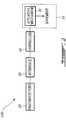
- FIG. 1shows a prosthesis (14) provided on one side of the lower body of an individual (10), the individual (10) having a healthy leg (12) on the other side.
- Artificial proprioceptors (20)are provided both on the healthy leg (12) and on the prosthesis (14).
- the prosthesis (14)comprises an actuating mechanism (16) which may be either passive or active.
- a passive actuating mechanismmay be generally defined as an electro-mechanical component that only absorbs mechanical energy in order to modify dynamics of mechanical joints of the prosthesis, while an active actuating mechanism may be generally defined as an electro-mechanical component that absorbs and supplies mechanical energy in order to modify dynamics of mechanical joints of the prosthesis.
- FIG. 2shows the control system (100) being combined with artificial proprioceptors (20) and a prosthesis (14) having an actuating mechanism (16), such as shown in FIG. 1 .
- the purpose of the control system (100)is to provide the required signals allowing to control the actuating mechanism (16). To do so, the control system (100) is interfaced with the amputee (10) using the artificial proprioceptors (20) to ensure proper coordination between the amputee (10) and the movements of the prosthesis (14).
- the set of artificial proprioceptors (20)captures information, in real time, about the dynamics of the amputee's movement and provide that information to the control system (100).
- the control system (100)is then used to determine the resistance to be applied to a joint, in the case of a passive actuating mechanism, or the joint trajectories and the required force or torque that must be applied by a joint, in the case of an active actuating mechanism, in order to provide coordinated movements.
- the present inventionis not limited to its use with the mechanical configuration illustrated in FIG. 1 .
- the control system (100)may be used with a leg prosthesis having more than one joint.
- itmay be used with a prosthesis having an ankle joint, a metatarsophalangeal joint or a hip joint in addition to a knee joint.
- a osseo-integrated devicescould also be used, ensuring a direct attachment between the mechanical component of the prosthesis and the amputee skeleton.
- Other kinds of prosthesesmay be used as well.
- the control system (100) shown in FIG. 2comprises an interface (30) through which data signals coming from the artificial proprioceptors (20) are received. They may be received either from an appropriate wiring or from a wireless transmission.
- the data signals from the artificial proprioceptors (20) provided on a healthy leg (12)are advantageously sent through the wireless transmission using an appropriate radio frequency (RF) module.
- RFradio frequency
- other combinations of communication link technologiesmay be used, such as wired, wireless, optical, etc.
- Software residing on a controller (40)contains all the algorithms enabling the control system (100) to provide the required signals allowing to control the actuating mechanism (16).
- the artificial proprioceptors (20), located on both the healthy leg (12) and the prosthesis (14),may include myoelectric sensors, neuro-sensors, kinematic sensors, kinetic sensors or plantar pressure sensors.
- Myoelectric sensorsare electrodes used to measure the internal or the external myoelectrical activity of skeletal muscles.
- Neuro-sensorsare electrodes used to measure the summation of one or more action potentials of peripheral nerves.
- Kinematic sensorsare used to measure the position of articulated joints, the mobility speed or acceleration of lower extremities.
- Kinetic sensorsare used to measure rotational forces at the articulated joints or reaction forces of lower extremities.
- Plantar pressure sensorsare used to measure the vertical plantar pressure of a specific underfoot area.
- additional types of sensorswhich provide information about various dynamics of human locomotion may be used.
- the use of artificial proprioceptors (20)is not restricted to a specific type of sensor, multiple types of sensors in various combinations may be used.
- the controller (40)ensures, in real-time, the decomposition of the locomotion of an individual (10) based on the information provided by the artificial proprioceptors (20).
- data signals received from individual artificial proprioceptors (20) located on both the healthy leg (12) and the prosthesis (14) of an individual (10)can provide enough information in order to control the actuating mechanism (16) of the prosthesis (14).
- the artificial proprioceptors (20)may comprise localized plantar pressure sensors, which measure the vertical plantar pressure of a specific underfoot area, combined with a pair of gyroscopes which measure the angular speed of body segments of the lower extremities and a kinematic sensor which measures the angle of the prosthesis (14) knee joint.
- the plantar pressure sensorsare used under both feet, the foot of the healthy leg (12) as well as the foot of the prosthesis (14).
- One of the gyroscopesis located at the shank of the healthy leg (12) while the other is located on the upper portion of the prosthesis (14) above the knee joint, i.e. at the residual thigh.
- the kinematic sensorAs for the kinematic sensor, it is located at the prosthesis (14) knee joint.
- the use of plantar pressure sensors, gyroscopes and kinematic sensorsis given as an example and does not limit the definition of artificial proprioceptors to such sensors.
- the plantar pressure sensors (20)are provided in a custom-made insole (18), preferably in the form of a standard orthopedic insole, that is modified to embed the two sensors (20) for the measurement of two localized plantar pressures.
- Each sensor (20)as shown in FIG. 5 , is preferably composed of a thin Force-Sensing Resistor (FSR) polymer cell (22) directly connected to the interface (30) or indirectly using an intermediary system (not shown), for instance a wireless emitter.
- the FSR cell (22)has a decreasing electrical resistance in response to an increasing force applied perpendicularly to the surface thereof.
- Each cell (22)outputs a time variable electrical signal for which the intensity is proportional to the total vertical plantar pressure over its surface area.
- the size and position of the plantar pressure sensors (20)were defined in accordance with the stability and the richness (intensity) of the localized plantar pressure signals provided by certain underfoot areas during locomotion.
- the PPMVPlantar Pressure Maximal Variation
- the PPMVwas defined as the maximum variation of the plantar pressure at a particular point (underfoot area of coordinate i,j) during locomotion.
- the X-Y axis (19) in FIG. 3was used to determine the i,j coordinates of each underfoot area. It was found by experimentation that the calcaneus and the Metatarsophalangeal (MP) regions are two regions of the foot sole where the PPMV may be considered as providing a signal that is both stable and rich in information.
- MPMetatarsophalangeal
- Table 1The normalized position of the pressure sensors and their size are shown in Table 1, where the length L and the width W are respectively the length and the width of the subject's foot. The coefficients in Table 1 have been obtained by experimentation. A typical diameter for the plantar pressure sensors (20) is between 20 and 30 mm. Table 1 - Normalized position and size of plantar pressure sensors Area Position (X, Y) Size (diameter) Calcaneus (0.51 ⁇ W, 0.14 ⁇ L) 0.29 ⁇ L ⁇ W MP (0.47 ⁇ W, 0.76 ⁇ L) 0.24 ⁇ L ⁇ W
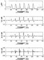
- FIGS. 5a to 5dshow examples of data signals from the four localized plantar pressure sensors (20) during a standard walking path at 109,5 steps/minute.
- the four signals, f r1 (t), f r2 (t), f r3 (t) and f r4 (t)correspond to the variation in time of the localized plantar pressure at the calcaneus region of the left foot ( FIG. 5a ), the MP region of the left foot ( FIG. 5b ), the calcaneus region of the right foot ( FIG. 5c ), and the MP region of the right foot ( FIG. 5d ).
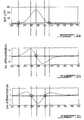
- FIGS. 6a to 6d and 7a to 7dshow examples of graphs of localized plantar pressures, as well as their first, second and third differentials, at the calcaneus and MP regions respectively, for a linear walking path of 109,5 steps/minute.
- FIGS. 8a to 8dshow graphically the zero crossings for a typical localized plantar pressure signal, and its first three differentials, at the calcaneous region conditions, which may be used by the controller (40) decompose the locomotion of the individual (10), while FIGS. 9a to 9c do so for the localized plantar pressure signal, and its first two differentials, at the MP region. This shows the relationships between the various data and derivative signals.
- the controller (40)may use the four localized plantar pressure signals, the first, the second and the third differentials of each of those four localized plantar pressure signals, as well as the information gathered from the data signals of the two gyroscopes and the kinematic sensor, in order to decompose the locomotion of the individual (10) into a finite number of portions, and generate the controls signals for controlling the actuating mechanism (16) in response to the data signals.
- the controller (40)is not limited to the use of the preceding data and derived signals.
- a controller (40) and control system (100) using artificial proprioceptors comprising plantar pressure sensors as well as gyroscopes and a kinematic sensoris described in US 2004/0049290 which is entitled “CONTROL SYSTEM AND METHOD FOR CONTROLLING AN ACTUATED PROSTHESIS", by Stéphane Bédard.
Landscapes
- Health & Medical Sciences (AREA)
- Life Sciences & Earth Sciences (AREA)
- Transplantation (AREA)
- General Health & Medical Sciences (AREA)
- Veterinary Medicine (AREA)
- Biomedical Technology (AREA)
- Heart & Thoracic Surgery (AREA)
- Engineering & Computer Science (AREA)
- Oral & Maxillofacial Surgery (AREA)
- Animal Behavior & Ethology (AREA)
- Public Health (AREA)
- Cardiology (AREA)
- Vascular Medicine (AREA)
- Orthopedic Medicine & Surgery (AREA)
- Dentistry (AREA)
- Physics & Mathematics (AREA)
- Biophysics (AREA)
- Pathology (AREA)
- Medical Informatics (AREA)
- Molecular Biology (AREA)
- Surgery (AREA)
- Prostheses (AREA)
Description
- The present invention relates to the positioning of lower extremities artificial proprioceptors for use with a control system and/or a method for controlling an actuated prosthesis. This invention is particularly well adapted for controlling an actuated leg prosthesis for above-knee amputees.
- As is well known to control engineers, the automation of complex mechanical systems is not something easy to achieve. Among such systems, conventional powered artificial limbs are notorious for having control problems. These conventional prostheses are equipped with basic controllers that artificially mobilize the joints without any interaction from the amputee and are only capable of generating basic motions. Such basic controllers do not take into consideration the dynamic conditions of the working environment, regardless the fact that the prosthesis is required to generate appropriate control within a practical application. They are generally lacking in predictive control strategies necessary to anticipate the artificial limb's response as well as lacking in adaptive regulation enabling the adjustment of the control parameters to the dynamics of the prosthesis. Because human limb mobility is a complex process including voluntary, reflex and random events at the same time, conventional prostheses do not have the capability to interact simultaneously with the human body and the external environment in order to have minimal appropriate functioning.
GB 2,201,260 A WO 96/41599 A1 WO 00/38599 A1 - It is an object of the invention to provide an improved approach having the capability to interact simultaneously with the human body and the external environment to a control systems and/or methods for controlling a dynamic prosthesis in order to fulfill the needs of amputees, in particular those of above-knee amputees.
- This object is achieved by a method of
claim 1, by a device of claim 26 and a prosthesis of claim 51. The dependent claims setout optional features. These and other aspects of the present invention are described in or apparent from the following detailed description, which description is made in conjunction with the accompanying figures. FIG. 1 shows the lower body of an individual provided with a prosthesis on one side and having a healthy leg on the other side.FIG. 2 is a block diagram showing a control system for a prosthesis having an actuating mechanism.FIG. 3 is an upper schematic view of an insole provided with plantar pressure sensors.FIG. 4 is a cross sectional view of a sensor shown inFIG. 3 .FIGS. 5a to 5d are examples of four data signals using plantar pressure sensors during typical walking on flat ground.FIGS. 6a to 6d give an example of a data signal obtained from a plantar pressure sensor at the calcaneus region and its first three differentials.FIGS. 7a to 7d give an example of a data signal obtained from a plantar pressure sensor at the metatarsophalangeal (MP) region and its first three differentials.FIGS. 8a to 8d give an example of the zero crossings for a typical localized plantar pressure signal, and its first three differentials, at the calcaneous region conditions.FIGS. 9a to 9c give an example of the zero crossings for a typical localized plantar pressure signal, and its first three differentials, at the metatarsophalangeal (MP) region.- The appended figures show positioning of lower extremities artificial proprioceptors (20) for use with a control system (100) and a method for controlling a prosthesis (14) having an actuating mechanism (16) in accordance with the preferred embodiment of the present invention. It should be understood that the present invention is not limited to the illustrated implementation since various changes and modifications may be effected herein without departing from the scope of the appended claims.
FIG. 1 shows a prosthesis (14) provided on one side of the lower body of an individual (10), the individual (10) having a healthy leg (12) on the other side. Artificial proprioceptors (20) are provided both on the healthy leg (12) and on the prosthesis (14). The prosthesis (14) comprises an actuating mechanism (16) which may be either passive or active. A passive actuating mechanism may be generally defined as an electro-mechanical component that only absorbs mechanical energy in order to modify dynamics of mechanical joints of the prosthesis, while an active actuating mechanism may be generally defined as an electro-mechanical component that absorbs and supplies mechanical energy in order to modify dynamics of mechanical joints of the prosthesis.- An example of a passive actuating mechanism is described in
US 2001/0029400 , entitled "ELECTRONICALLY CONTROLLED PROSTHETIC KNEE". Examples of active actuating mechanisms are described inUS2004/0111163 entitled "ACTUATED PROSTHESIS FOR ABOVE-KNEE AMPUTEES", by Stephane Bédard et al. FIG. 2 shows the control system (100) being combined with artificial proprioceptors (20) and a prosthesis (14) having an actuating mechanism (16), such as shown inFIG. 1 . The purpose of the control system (100) is to provide the required signals allowing to control the actuating mechanism (16). To do so, the control system (100) is interfaced with the amputee (10) using the artificial proprioceptors (20) to ensure proper coordination between the amputee (10) and the movements of the prosthesis (14). The set of artificial proprioceptors (20) captures information, in real time, about the dynamics of the amputee's movement and provide that information to the control system (100). The control system (100) is then used to determine the resistance to be applied to a joint, in the case of a passive actuating mechanism, or the joint trajectories and the required force or torque that must be applied by a joint, in the case of an active actuating mechanism, in order to provide coordinated movements.- It should be noted that the present invention is not limited to its use with the mechanical configuration illustrated in
FIG. 1 . The control system (100) may be used with a leg prosthesis having more than one joint. For instance, it may be used with a prosthesis having an ankle joint, a metatarsophalangeal joint or a hip joint in addition to a knee joint. Moreover, instead of a conventional socket a osseo-integrated devices could also be used, ensuring a direct attachment between the mechanical component of the prosthesis and the amputee skeleton. Other kinds of prostheses may be used as well. - The control system (100) shown in
FIG. 2 comprises an interface (30) through which data signals coming from the artificial proprioceptors (20) are received. They may be received either from an appropriate wiring or from a wireless transmission. The data signals from the artificial proprioceptors (20) provided on a healthy leg (12) are advantageously sent through the wireless transmission using an appropriate radio frequency (RF) module. Of course, other combinations of communication link technologies may be used, such as wired, wireless, optical, etc. - Software residing on a controller (40) contains all the algorithms enabling the control system (100) to provide the required signals allowing to control the actuating mechanism (16).
- The artificial proprioceptors (20), located on both the healthy leg (12) and the prosthesis (14), may include myoelectric sensors, neuro-sensors, kinematic sensors, kinetic sensors or plantar pressure sensors. Myoelectric sensors are electrodes used to measure the internal or the external myoelectrical activity of skeletal muscles. Neuro-sensors are electrodes used to measure the summation of one or more action potentials of peripheral nerves. Kinematic sensors are used to measure the position of articulated joints, the mobility speed or acceleration of lower extremities. Kinetic sensors are used to measure rotational forces at the articulated joints or reaction forces of lower extremities. Plantar pressure sensors are used to measure the vertical plantar pressure of a specific underfoot area. Of course, additional types of sensors which provide information about various dynamics of human locomotion may be used. For a given application, the use of artificial proprioceptors (20) is not restricted to a specific type of sensor, multiple types of sensors in various combinations may be used.
- The controller (40) ensures, in real-time, the decomposition of the locomotion of an individual (10) based on the information provided by the artificial proprioceptors (20). In accordance with the present invention, it was found that data signals received from individual artificial proprioceptors (20) located on both the healthy leg (12) and the prosthesis (14) of an individual (10) can provide enough information in order to control the actuating mechanism (16) of the prosthesis (14). For instance, in the case of plantar pressure sensors, it has been noticed experimentally that the slope (first derivative), the sign of the concavity (second derivative) and the slope of concavity (third derivative) of the data signals received from plantar pressure sensors, and of combinations of those signals, give highly accurate and stable information on the human locomotion and enable the decomposition of the human locomotion into a finite number of portions. This breakdown ensures the proper identification of the complete mobility dynamics of the lower extremities in order to model the human locomotion. Of course, the use of plantar pressure sensors is given as an example and does not limit the definition of artificial proprioceptors to such sensors.
- In a sample application, the artificial proprioceptors (20) may comprise localized plantar pressure sensors, which measure the vertical plantar pressure of a specific underfoot area, combined with a pair of gyroscopes which measure the angular speed of body segments of the lower extremities and a kinematic sensor which measures the angle of the prosthesis (14) knee joint. The plantar pressure sensors are used under both feet, the foot of the healthy leg (12) as well as the foot of the prosthesis (14). One of the gyroscopes is located at the shank of the healthy leg (12) while the other is located on the upper portion of the prosthesis (14) above the knee joint, i.e. at the residual thigh. As for the kinematic sensor, it is located at the prosthesis (14) knee joint. Of course, the use of plantar pressure sensors, gyroscopes and kinematic sensors is given as an example and does not limit the definition of artificial proprioceptors to such sensors.
- In
FIG. 4 , the plantar pressure sensors (20) are provided in a custom-made insole (18), preferably in the form of a standard orthopedic insole, that is modified to embed the two sensors (20) for the measurement of two localized plantar pressures. Each sensor (20), as shown inFIG. 5 , is preferably composed of a thin Force-Sensing Resistor (FSR) polymer cell (22) directly connected to the interface (30) or indirectly using an intermediary system (not shown), for instance a wireless emitter. The FSR cell (22) has a decreasing electrical resistance in response to an increasing force applied perpendicularly to the surface thereof. Each cell (22) outputs a time variable electrical signal for which the intensity is proportional to the total vertical plantar pressure over its surface area. The size and position of the plantar pressure sensors (20) were defined in accordance with the stability and the richness (intensity) of the localized plantar pressure signals provided by certain underfoot areas during locomotion. - Experimentation provided numerous data concerning the spatial distribution of foot pressures and more specifically on the Plantar Pressure Maximal Variation (PPMV) during locomotion. The PPMV was defined as the maximum variation of the plantar pressure at a particular point (underfoot area of coordinate i,j) during locomotion. The X-Y axis (19) in
FIG. 3 was used to determine the i,j coordinates of each underfoot area. It was found by experimentation that the calcaneus and the Metatarsophalangeal (MP) regions are two regions of the foot sole where the PPMV may be considered as providing a signal that is both stable and rich in information. - The normalized position of the pressure sensors and their size are shown in Table 1, where the length L and the width W are respectively the length and the width of the subject's foot. The coefficients in Table 1 have been obtained by experimentation. A typical diameter for the plantar pressure sensors (20) is between 20 and 30 mm.
Table 1 - Normalized position and size of plantar pressure sensors Area Position (X, Y) Size (diameter) Calcaneus (0.51·W, 0.14·L) 
MP (0.47·W, 0.76·L) 
FIGS. 5a to 5d show examples of data signals from the four localized plantar pressure sensors (20) during a standard walking path at 109,5 steps/minute. The four signals,fr1(t),fr2(t),fr3(t) andfr4(t), correspond to the variation in time of the localized plantar pressure at the calcaneus region of the left foot (FIG. 5a ), the MP region of the left foot (FIG. 5b ), the calcaneus region of the right foot (FIG. 5c ), and the MP region of the right foot (FIG. 5d ).FIGS. 6a to 6d and7a to 7d show examples of graphs of localized plantar pressures, as well as their first, second and third differentials, at the calcaneus and MP regions respectively, for a linear walking path of 109,5 steps/minute.FIGS. 8a to 8d show graphically the zero crossings for a typical localized plantar pressure signal, and its first three differentials, at the calcaneous region conditions, which may be used by the controller (40) decompose the locomotion of the individual (10), whileFIGS. 9a to 9c do so for the localized plantar pressure signal, and its first two differentials, at the MP region. This shows the relationships between the various data and derivative signals.- Accordingly, the controller (40) may use the four localized plantar pressure signals, the first, the second and the third differentials of each of those four localized plantar pressure signals, as well as the information gathered from the data signals of the two gyroscopes and the kinematic sensor, in order to decompose the locomotion of the individual (10) into a finite number of portions, and generate the controls signals for controlling the actuating mechanism (16) in response to the data signals. Of course, the controller (40) is not limited to the use of the preceding data and derived signals.
- A controller (40) and control system (100) using artificial proprioceptors comprising plantar pressure sensors as well as gyroscopes and a kinematic sensor is described in
US 2004/0049290 which is entitled "CONTROL SYSTEM AND METHOD FOR CONTROLLING AN ACTUATED PROSTHESIS", by Stéphane Bédard.


Claims (51)
- A method of controlling an actuating mechanism (16) of a prosthesis (14) provided on one side of the lower body of an individual (10), the individual (10) having a healthy leg (12) on the other side, the method comprising:providing at least one of a plurality of artificial proprioceptors (20) on the side of the healthy leg (12);characterized byproviding at least one of the plurality of artificial proprioceptors (20) on the prosthesis (14), wherein the at least one of the artificial proprioceptors (20) being on the side of the healthy leg (12) comprises a first plantar pressure sensor, and the at least one of the artificial proprioceptors (20) being on the side of the prosthesis (14) comprises a second plantar pressure sensor;generating data signals in real time at the artificial proprioceptors (20); andgenerating control signals in real time for controlling the actuating mechanism (16) in response to the data signals.
- A method according to claim 1,characterized in that at least one of the data signals is supplied via a wired connection.
- A method according to claim 1,characterized in that at least one of the data signals is supplied via a wireless connection.
- A method according to claim 1,characterized in that the actuating mechanism (16) is a passive electro-mechanical component that absorbs mechanical energy in order to modify dynamics of mechanical joints of the prosthesis (14).
- A method according to claim 1,characterized in that the actuating mechanism (16) is an active electro-mechanical component that absorbs and supplies mechanical energy in order to modify dynamics of mechanical joints of the prosthesis (14).
- A method according to claim 1,characterized in that the artificial proprioceptors (20) include myoelectric sensors.
- A method according to claim 6,characterized in that the myoelectric sensors include external electrodes to measure myoelectric activity of skeletal muscles of the individual (10).
- A method according to claim 6,characterized in that the myoelectric sensors include internal electrodes to measure myoelectric activity of skeletal muscles of the individual (10).
- A method according to claim 1,characterized in that the artificial proprioceptors (20) include neuro-sensors.
- A method according to claim 9,characterized in that the neuro-sensors are electrodes to measure the summation of one or more action potentials of peripheral nerves of the individual (10).
- A method according to claim 1,characterized in that the artificial proprioceptors (20) include kinematic sensors.
- A method according to claim 11,characterized in that the kinematic sensors include means for measuring the position of articulated joints of lower extremities parts of the individual (10).
- A method according to claim 11,characterized in that the kinematic sensors include means for measuring the mobility speed of lower extremities parts of the individual (10).
- A method according to claim 11,characterized in that the kinematic sensors include means for measuring the mobility acceleration of lower extremities parts of the individual (10).
- A method according to claim 11,characterized in that at least one of the kinematic sensors is located at the shank of the healthy leg (12) of the individual (10).
- A method according to claim 11,characterized in that at least one of the kinematic sensors is located at a socket of the prosthesis (14).
- A method according to claim 1,characterized in that the artificial proprioceptors (20) include kinetic sensors.
- A method according to claim 17,characterized in that the kinetic sensors include means for measuring rotational forces at articulated joints of lower extremities parts of the individual (10).
- A method according to claim 17,characterized in that the kinetic sensors include means for measuring reaction forces at lower extremities parts of the individual (10).
- A method according to claim 17,characterized in that at least one of the kinetic sensors is located at a transtibial post of the prosthesis (14).
- A method according to claim 1,characterized in that the at least one of the artificial proprioceptors (20) being on the side of the healthy leg (12) includes the first plantar pressure sensor and the at least one of the artificial proprioceptors (20) being on the side of the prosthesis (14) includes the second plantar pressure sensor.
- A method according to claim 21,characterized in that the first and second plantar pressure sensors include force-sensing resistors measuring the pressure forces at underfoot areas into at least one human body plan.
- A method according to claim 21,characterized in that the first plantar pressure sensor is located at a metatarsophalangeal region of a foot of the healthy leg (12) and another first plantar pressure sensor is located at a calcaneus region of the foot of the healthy leg (12).
- A method according to claim 23,characterized in that the second plantar pressure sensor is located at a metatarsophalangeal region of a prosthetic foot of the prosthesis (14) and another second plantar pressure sensor is located at a calcaneus region of the prosthetic foot of the prosthesis (14).
- A method according to claim 23,characterized in that the first and second localized plantar pressure sensors are combined with a pair of gyroscopes which measure the angular speed of body segments of the lower extremities and a kinematic sensor which measures the angle of the prosthesis (14) knee joint.
- A device for controlling an actuating mechanism (16) of a prosthesis (14) provided on one side of the lower body of an individual (10), the individual (10) having a healthy leg (12) on the other side, the device comprising:at least one of a plurality of artificial proprioceptors (20) on the side of the healthy leg (12);characterized byat least one of the plurality of artificial proprioceptors (20) provided on the prosthesis (14), wherein the at least one of the artificial proprioceptors (20) being on the side of the healthy leg (12) comprises a first plantar pressure sensor, and the at least one of the artificial proprioceptors (20) being on the side of the prosthesis (14) comprises a second plantar pressure sensor;means for generating data signals in real time at the artificial proprioceptors (20); andmeans for generating control signals in real time for controlling the actuating mechanism (16) in response to the data signals.
- A device according to claim 26,characterized in that at least one of the data signals is supplied via a wired connection.
- A device according to claim 26,characterized in that at least one of the data signals is supplied via a wireless connection.
- A device according to claim 26,characterized in that the actuating mechanism (16) is a passive electro-mechanical component that absorbs mechanical energy in order to modify dynamics of mechanical joints of the prosthesis (14).
- A device according to claim 26,characterized in that the actuating mechanism (16) is an active electro-mechanical component that absorbs and supplies mechanical energy in order to modify dynamics of mechanical joints of the prosthesis (14).
- A device according to claim 26,characterized in that the artificial proprioceptors (20) include myoelectric sensors.
- A device according to claim 31,characterized in that the myoelectric sensors include external electrodes to measure myoelectric activity of skeletal muscles of the individual (10).
- A device according to claim 31,characterized in that the myoelectric sensors include internal electrodes to measure myoelectric activity of skeletal muscles of the individual (10).
- A device according to claim 26,characterized in that the artificial proprioceptors (20) include neuro-sensors.
- A device according to claim 34,characterized in that the neuro-sensors are electrodes to measure the summation of one or more action potentials of peripheral nerves of the individual (10).
- A device according to claim 26,characterized in that the artificial proprioceptors (20) include kinematic sensors.
- A device according to claim 36,characterized in that the kinematic sensors include means for measuring the position of articulated joints of lower extremities parts of the individual (10).
- A device according to claim 36,characterized in that the kinematic sensors include means for measuring the mobility speed of lower extremities parts of the individual (10).
- A device according to claim 36,characterized in that the kinematic sensors include means for measuring the mobility acceleration of lower extremities parts of the individual (10).
- A device according to claim 36,characterized in that at least one of the kinematic sensors is located at the shank of the healthy leg (12) of the individual (10).
- A device according to claim 36,characterized in that at least one of the kinematic sensors is located at a socket of the prosthesis (14).
- A device according to claim 36,characterized in that the artificial proprioceptors (20) include kinetic sensors.
- A device according to claim 42,characterized in that the kinetic sensors include means for measuring rotational forces at articulated joints of lower extremities parts of the individual (10).
- A device according to claim 42,characterized in that the kinetic sensors include means for measuring reaction forces at lower extremities parts of the individual (10).
- A device according to claim 42,characterized in that at least one of the kinetic sensors is located at a transtibial post of the prosthesis (14).
- A device according to claim 26,characterized in that the at least one of the artificial proprioceptors (20) being on the side of the healthy leg (12) includes the first plantar pressure sensor and the at least one of the artificial proprioceptors (20) being on the side of the prosthesis (14) includes the second plantar pressure sensor.
- A device according to claim 46,characterized in that the first and second plantar pressure sensors include force-sensing resistors measuring the pressure forces at underfoot areas into at least one human body plan.
- A device according to claim 46,characterized in that the first plantar pressure sensor is located at a metatarsophalangeal region of a foot of the healthy leg (12) and another first plantar pressure sensor is located at a calcaneus region of the foot of the healthy leg (12).
- A device according to claim 48,characterized in that the second plantar pressure sensor is located at a metatarsophalangeal region of a prosthetic foot of the prosthesis (14) and another second plantar pressure sensor is located at a calcaneus region of the prosthetic foot of the prosthesis (14).
- A device according to claim 26,characterized in that the first and second localized plantar pressure sensors are combined with a pair of gyroscopes which measure the angular speed of body segments of the lower extremities and a kinematic sensor which measures the angle of the prosthesis (14) knee joint.
- A lower extremities prosthesis (14) provided on one side of the lower body of an individual (10), the individual (10) having a healthy leg (12) on the other side, the prosthesis beingcharacterized in that it comprises:at least one actuating mechanism (16); anda device according to one of claims 26 to 50 for controlling the at least one actuating mechanism (16).
Applications Claiming Priority (3)
| Application Number | Priority Date | Filing Date | Title |
|---|---|---|---|
| US40528102P | 2002-08-22 | 2002-08-22 | |
| US405281P | 2002-08-22 | ||
| PCT/CA2003/001120WO2004017871A2 (en) | 2002-08-22 | 2003-07-25 | Positioning of lower extremities artificial proprioceptors |
Publications (2)
| Publication Number | Publication Date |
|---|---|
| EP1542627A2 EP1542627A2 (en) | 2005-06-22 |
| EP1542627B1true EP1542627B1 (en) | 2018-03-21 |
Family
ID=34272304
Family Applications (1)
| Application Number | Title | Priority Date | Filing Date |
|---|---|---|---|
| EP03792057.6AExpired - LifetimeEP1542627B1 (en) | 2002-08-22 | 2003-07-25 | Positioning of lower extremities artificial proprioceptors |
Country Status (7)
| Country | Link |
|---|---|
| US (1) | US7137998B2 (en) |
| EP (1) | EP1542627B1 (en) |
| JP (2) | JP4990497B2 (en) |
| KR (1) | KR100694282B1 (en) |
| CN (1) | CN100384391C (en) |
| AU (1) | AU2003250679B2 (en) |
| CA (1) | CA2494363C (en) |
Families Citing this family (84)
| Publication number | Priority date | Publication date | Assignee | Title |
|---|---|---|---|---|
| US7736394B2 (en) | 2002-08-22 | 2010-06-15 | Victhom Human Bionics Inc. | Actuated prosthesis for amputees |
| CN100506189C (en) | 2002-08-22 | 2009-07-01 | 维克多姆人体机械公司 | Actuated leg prosthesis for above-knee amputees |
| US7186270B2 (en)* | 2002-10-15 | 2007-03-06 | Jeffrey Elkins 2002 Corporate Trust | Foot-operated controller |
| US8956421B2 (en) | 2007-02-06 | 2015-02-17 | Deka Products Limited Partnership | Dynamic support apparatus and system |
| US8074559B2 (en) | 2007-02-06 | 2011-12-13 | Deka Products Limited Partnership | Dynamic support apparatus and system |
| US7198071B2 (en)* | 2003-05-02 | 2007-04-03 | Össur Engineering, Inc. | Systems and methods of loading fluid in a prosthetic knee |
| US7815689B2 (en) | 2003-11-18 | 2010-10-19 | Victhom Human Bionics Inc. | Instrumented prosthetic foot |
| US20050107889A1 (en) | 2003-11-18 | 2005-05-19 | Stephane Bedard | Instrumented prosthetic foot |
| US7811334B2 (en) | 2004-02-12 | 2010-10-12 | Ossur Hf. | System and method for motion-controlled foot unit |
| US7637959B2 (en) | 2004-02-12 | 2009-12-29 | össur hf | Systems and methods for adjusting the angle of a prosthetic ankle based on a measured surface angle |
| US8057550B2 (en) | 2004-02-12 | 2011-11-15 | össur hf. | Transfemoral prosthetic systems and methods for operating the same |
| JP2005230207A (en)* | 2004-02-19 | 2005-09-02 | Japan Labour Health & Welfare Organization | Above-knee prosthesis controlled by healthy leg |
| CA2559890C (en) | 2004-03-10 | 2014-01-07 | Ossur Hf | Control system and method for a prosthetic knee |
| WO2005110293A2 (en) | 2004-05-07 | 2005-11-24 | Ossur Engineering, Inc. | Magnetorheologically actuated prosthetic knee |
| CA2863933C (en) | 2004-12-22 | 2018-08-07 | Ossur Hf | Systems and methods for processing limb motion |
| EP1843724B1 (en) | 2005-02-02 | 2018-07-25 | Össur hf | Sensing systems and methods for monitoring gait dynamics |
| CA2601778C (en) | 2005-02-02 | 2014-08-12 | Ossur Hf | Prosthetic and orthotic systems usable for rehabilitation |
| US8801802B2 (en) | 2005-02-16 | 2014-08-12 | össur hf | System and method for data communication with a mechatronic device |
| SE528516C2 (en) | 2005-04-19 | 2006-12-05 | Lisa Gramnaes | Combined active and passive leg prosthesis system and a method for performing a movement cycle with such a system |
| EP1946429B1 (en) | 2005-08-10 | 2017-06-21 | Bionic Power Inc. | Methods and apparatus for harvesting biomechanical energy |
| US7485152B2 (en) | 2005-08-26 | 2009-02-03 | The Ohio Willow Wood Company | Prosthetic leg having electronically controlled prosthetic knee with regenerative braking feature |
| US8852292B2 (en) | 2005-09-01 | 2014-10-07 | Ossur Hf | System and method for determining terrain transitions |
| US8048172B2 (en) | 2005-09-01 | 2011-11-01 | össur hf | Actuator assembly for prosthetic or orthotic joint |
| US7531006B2 (en)* | 2005-09-01 | 2009-05-12 | össur hf | Sensing system and method for motion-controlled foot unit |
| FR2908293B1 (en)* | 2006-11-15 | 2009-07-31 | Commissariat Energie Atomique | DEVICE AND METHOD FOR MONITORING THE MOVEMENT OF A LIVING BEING |
| WO2008080232A1 (en) | 2007-01-05 | 2008-07-10 | Victhom Human Bionics Inc. | High torque active mechanism for orthotic and/or prosthetic devices |
| CA2673399C (en) | 2007-01-05 | 2017-08-29 | Victhom Human Bionics, Inc. | Joint actuation mechanism for a prosthetic and/or orthotic device having a compliant transmission |
| CA2676067C (en) | 2007-01-19 | 2017-06-20 | Victhom Human Bionics, Inc. | Reactive layer control system for prosthetic and orthotic devices |
| US9114028B2 (en) | 2007-02-06 | 2015-08-25 | Deka Products Limited Partnership | Arm prosthetic device |
| WO2008098053A1 (en)* | 2007-02-06 | 2008-08-14 | Deka Integrated Solutions Corp. | Dynamic support apparatus |
| US8979943B2 (en) | 2007-02-06 | 2015-03-17 | Deka Products Limited Partnership | Arm prosthetic device |
| US10426638B2 (en) | 2007-02-06 | 2019-10-01 | Deka Products Limited Partnership | Arm prosthetic device |
| US9114030B2 (en)* | 2007-02-06 | 2015-08-25 | Deka Products Limited Partnership | System for control of a prosthetic device |
| US11779476B2 (en) | 2007-02-06 | 2023-10-10 | Deka Products Limited Partnership | Arm prosthetic device |
| US8864845B2 (en)* | 2007-02-06 | 2014-10-21 | DEKA Limited Partnership | System for control of a prosthetic device |
| US9381099B2 (en) | 2007-02-06 | 2016-07-05 | Deka Products Limited Partnership | Arm prosthetic device |
| US8449624B2 (en)* | 2007-02-06 | 2013-05-28 | Deka Products Limited Partnership | Arm prosthetic device |
| WO2008098059A2 (en) | 2007-02-06 | 2008-08-14 | Deka Integrated Solutions Corp. | Method and apparatus for control of a prosthetic |
| EP1955679B1 (en)* | 2007-02-09 | 2013-11-06 | Semiconductor Energy Laboratory Co., Ltd. | Assist device |
| US8652218B2 (en)* | 2008-04-21 | 2014-02-18 | Vanderbilt University | Powered leg prosthesis and control methodologies for obtaining near normal gait |
| US9180025B2 (en) | 2008-04-21 | 2015-11-10 | Vanderbilt University | Powered leg prosthesis and control methodologies for obtaining near normal gait |
| US8685093B2 (en) | 2009-01-23 | 2014-04-01 | Warsaw Orthopedic, Inc. | Methods and systems for diagnosing, treating, or tracking spinal disorders |
| US8126736B2 (en) | 2009-01-23 | 2012-02-28 | Warsaw Orthopedic, Inc. | Methods and systems for diagnosing, treating, or tracking spinal disorders |
| EP2419057B1 (en)* | 2009-04-13 | 2014-10-01 | DEKA Products Limited Partnership | System and apparatus for orientation control |
| US9017418B2 (en)* | 2009-05-05 | 2015-04-28 | össur hf | Control systems and methods for prosthetic or orthotic devices |
| DE102009052887B4 (en)* | 2009-11-13 | 2016-09-15 | Otto Bock Healthcare Products Gmbh | Method for controlling an orthotic or prosthetic joint of a lower extremity |
| US8389977B2 (en)* | 2009-12-10 | 2013-03-05 | Transphorm Inc. | Reverse side engineered III-nitride devices |
| WO2011127410A2 (en) | 2010-04-09 | 2011-10-13 | Deka Products Limited Partnership | System and apparatus for robotic device and methods of using thereof |
| EP2590598B1 (en) | 2010-07-07 | 2019-03-13 | Össur HF | Ground contact sensing systems and methods for lower-limb orthotic and prosthetic devices |
| CA2812955C (en) | 2010-09-29 | 2018-09-04 | Ossur Hf | Prosthetic and orthotic devices and methods and systems for controlling the same |
| US9060884B2 (en) | 2011-05-03 | 2015-06-23 | Victhom Human Bionics Inc. | Impedance simulating motion controller for orthotic and prosthetic applications |
| US8736087B2 (en) | 2011-09-01 | 2014-05-27 | Bionic Power Inc. | Methods and apparatus for control of biomechanical energy harvesting |
| US9532877B2 (en) | 2011-11-11 | 2017-01-03 | Springactive, Inc. | Robotic device and method of using a parallel mechanism |
| US10543109B2 (en) | 2011-11-11 | 2020-01-28 | Össur Iceland Ehf | Prosthetic device and method with compliant linking member and actuating linking member |
| US9017419B1 (en) | 2012-03-09 | 2015-04-28 | össur hf | Linear actuator |
| KR101371359B1 (en)* | 2012-03-20 | 2014-03-19 | 한국과학기술연구원 | Peripheral Nerve Interface System and Method for Prosthetic Hand Control |
| US9044346B2 (en) | 2012-03-29 | 2015-06-02 | össur hf | Powered prosthetic hip joint |
| CN102670218B (en)* | 2012-05-15 | 2014-08-20 | 北京大学 | Wearable foot bottom pressure acquisition device for artificial limb control |
| US9259343B2 (en) | 2012-07-06 | 2016-02-16 | Newman Technologies LLC | Device for mitigating plantar fasciitis |
| WO2014043681A2 (en) | 2012-09-17 | 2014-03-20 | Vanderbilt University | Walking controller for powered ankle prostheses |
| KR101476889B1 (en)* | 2012-10-05 | 2014-12-29 | 인하대학교 산학협력단 | Walking assistance device and drive method |
| US9561118B2 (en) | 2013-02-26 | 2017-02-07 | össur hf | Prosthetic foot with enhanced stability and elastic energy return |
| US9192487B2 (en) | 2013-03-11 | 2015-11-24 | Arizona Board Of Regents On Behalf Of Arizona State University | Joint control systems and methods utilizing muscle activation sensing |
| WO2014159114A1 (en) | 2013-03-14 | 2014-10-02 | össur hf | Prosthetic ankle: a method of controlling based on adaptation to speed |
| CN103405293A (en)* | 2013-08-16 | 2013-11-27 | 北京中科创睿科技有限公司 | Intelligent joint assembly and intelligent artificial limb using same |
| US9333345B2 (en) | 2013-10-03 | 2016-05-10 | Ensilver Canada | Electrical stimulation for a functional electrical stimulation system |
| US9375570B2 (en) | 2013-10-03 | 2016-06-28 | Ensilver Canada | Sensor unit for a functional electrical stimulation (FES) orthotic system |
| CA2866027A1 (en) | 2013-10-03 | 2015-04-03 | Farsad Kiani | Controller unit for a functional electrical stimulation (fes) orthotic system |
| US10369023B2 (en) | 2013-11-01 | 2019-08-06 | Rehabilitation Institute Of Chicago | Impedance parameter power control for lower limb assistive device |
| WO2015157723A1 (en) | 2014-04-11 | 2015-10-15 | össur hf | Prosthetic foot with removable flexible members |
| CN103950038B (en)* | 2014-04-25 | 2016-03-30 | 大连楚云天科技开发有限公司 | Mechanical joint and biomimetic mechanical dinosaur neck, tail structure |
| US9364657B2 (en) | 2014-10-31 | 2016-06-14 | Ensilver Canada | Cuff unit for a functional electrical stimulation system |
| WO2016141364A1 (en) | 2015-03-04 | 2016-09-09 | Freedom Innovations, Llc | Lower limb prosthesis |
| CN104856706B (en)* | 2015-04-29 | 2018-04-24 | 盐城工学院 | Knee joint mechanical characteristics test equipment |
| WO2017049234A1 (en) | 2015-09-18 | 2017-03-23 | Ossur Iceland Ehf | Magnetic locking mechanism for prosthetic or orthotic joints |
| WO2017070282A1 (en)* | 2015-10-21 | 2017-04-27 | Schroeder James E | Controlling and identifying optimal nerve/muscle monitoring sites and training a prosthetic or orthotic device |
| CN105438310B (en)* | 2015-12-17 | 2017-09-08 | 常州大学 | Anthropomorphic robot two-freedom parallel connection shock resistance machinery foot |
| US10195099B2 (en) | 2016-01-11 | 2019-02-05 | Bionic Power Inc. | Method and system for intermittently assisting body motion |
| US10675456B2 (en) | 2016-09-20 | 2020-06-09 | Robert Madeira | System and methods for percutaneous mechanical and/or neural interface |
| JP6793203B2 (en)* | 2016-11-18 | 2020-12-02 | Cyberdyne株式会社 | Artificial limb movement assisting device and artificial limb movement assisting method |
| WO2018191755A1 (en)* | 2017-04-14 | 2018-10-18 | REHABILITATION INSTITUTE OF CHICAGO d/b/a Shirley Ryan AbilityLab | Prosthetic virtual reality training interface and related methods |
| CN107320223B (en)* | 2017-06-30 | 2019-03-29 | 国家康复辅具研究中心 | Artificial leg is automatically to line method and device |
| US20190209347A1 (en)* | 2018-01-09 | 2019-07-11 | Ashvin Saikumar Irrinki | Synergetic Prosthesis |
| US12330734B2 (en)* | 2022-04-15 | 2025-06-17 | Fox Factory, Inc. | Active suspension and body wearable device integration |
Family Cites Families (22)
| Publication number | Priority date | Publication date | Assignee | Title |
|---|---|---|---|---|
| US52663A (en)* | 1866-02-20 | Improvement in sleds | ||
| FR2293185A1 (en) | 1974-12-02 | 1976-07-02 | Bernard Jean | Artificial leg with actuator - has unit on good leg moved by body weight coupled by flexible guide to receiver |
| US4558704A (en) | 1983-12-15 | 1985-12-17 | Wright State University | Hand control system |
| US4805455A (en)* | 1987-04-24 | 1989-02-21 | Myo-Tech Corp. | Muscle testing apparatus and method |
| GB2201260B (en)* | 1987-02-07 | 1991-02-13 | Christopher Charles Box | A method of control of a mechanised artificial leg |
| FR2623086B1 (en) | 1987-11-17 | 1994-03-18 | Adcro Section Ceraval | PROSTHETIC KNEE CONTROLLED BY A MICROPROCESSOR |
| GB2216426B (en) | 1988-03-25 | 1992-09-30 | Kobe Steel Ltd | Programmable leg prosthesis |
| CN2043873U (en)* | 1988-11-21 | 1989-09-06 | 张红军 | One-sided mobile artificial legs |
| US5383939A (en) | 1991-12-05 | 1995-01-24 | James; Kelvin B. | System for controlling artificial knee joint action in an above knee prosthesis |
| DE4229330A1 (en)* | 1992-09-02 | 1994-03-10 | Ludger Springob | Limb function restoration using somatronic device - has microchip which responds to detected movement of sound limb to provide signals for stimulating impaired limb |
| GB9312131D0 (en) | 1993-06-11 | 1993-07-28 | Blatchford & Sons Ltd | Prosthesis control system |
| DE19521464C2 (en)* | 1995-06-13 | 1999-08-19 | Leuven K U Res & Dev | Procedure for controlling the knee brake of a prosthetic knee joint and thigh prosthesis |
| GB2302949B (en)* | 1995-07-01 | 1999-04-14 | Univ Salford | A transducer |
| US5779735A (en) | 1996-05-17 | 1998-07-14 | Molino; Joseph L. | Knee unit for above-knee prosthetic leg |
| US6113642A (en) | 1996-06-27 | 2000-09-05 | Mauch, Inc. | Computer controlled hydraulic resistance device for a prosthesis and other apparatus |
| US5888212A (en) | 1997-06-26 | 1999-03-30 | Mauch, Inc. | Computer controlled hydraulic resistance device for a prosthesis and other apparatus |
| US6695885B2 (en)* | 1997-02-26 | 2004-02-24 | Alfred E. Mann Foundation For Scientific Research | Method and apparatus for coupling an implantable stimulator/sensor to a prosthetic device |
| DE19754690A1 (en)* | 1997-12-10 | 1999-07-01 | Biedermann Motech Gmbh | Leg prosthesis with an artificial knee joint with a control device |
| CN1089011C (en)* | 1998-12-04 | 2002-08-14 | 清华大学 | Functional neuromyo-electric signal identification and stimulation apparatus |
| DE19859931A1 (en)* | 1998-12-24 | 2000-07-06 | Biedermann Motech Gmbh | Prosthesis with an artificial knee joint and method for controlling a prosthetic leg |
| EP1255517B1 (en)* | 2000-01-20 | 2005-08-03 | Massachusetts Institute of Technology | Electronically controlled prosthetic knee |
| JP4411622B2 (en) | 2000-03-29 | 2010-02-10 | マサチューセッツ・インスティテュート・オブ・テクノロジー | Lower limb artificial joint system and control method thereof |
- 2003
- 2003-07-25KRKR1020057002936Apatent/KR100694282B1/ennot_activeExpired - Fee Related
- 2003-07-25JPJP2004529610Apatent/JP4990497B2/ennot_activeExpired - Fee Related
- 2003-07-25EPEP03792057.6Apatent/EP1542627B1/ennot_activeExpired - Lifetime
- 2003-07-25AUAU2003250679Apatent/AU2003250679B2/ennot_activeCeased
- 2003-07-25USUS10/627,503patent/US7137998B2/ennot_activeExpired - Lifetime
- 2003-07-25CACA002494363Apatent/CA2494363C/ennot_activeExpired - Fee Related
- 2003-07-25CNCNB038198797Apatent/CN100384391C/ennot_activeExpired - Fee Related
- 2010
- 2010-08-13JPJP2010181195Apatent/JP2010253301A/ennot_activeWithdrawn
Also Published As
| Publication number | Publication date |
|---|---|
| AU2003250679B2 (en) | 2006-04-27 |
| KR20050042793A (en) | 2005-05-10 |
| US20040088057A1 (en) | 2004-05-06 |
| US7137998B2 (en) | 2006-11-21 |
| JP2005536252A (en) | 2005-12-02 |
| CA2494363A1 (en) | 2004-03-04 |
| KR100694282B1 (en) | 2007-03-14 |
| JP2010253301A (en) | 2010-11-11 |
| CN100384391C (en) | 2008-04-30 |
| CA2494363C (en) | 2009-04-28 |
| AU2003250679A1 (en) | 2004-03-11 |
| CN1678259A (en) | 2005-10-05 |
| JP4990497B2 (en) | 2012-08-01 |
| EP1542627A2 (en) | 2005-06-22 |
Similar Documents
| Publication | Publication Date | Title |
|---|---|---|
| EP1542627B1 (en) | Positioning of lower extremities artificial proprioceptors | |
| WO2004017871A2 (en) | Positioning of lower extremities artificial proprioceptors | |
| Farina et al. | Toward higher-performance bionic limbs for wider clinical use | |
| US9526636B2 (en) | Instrumented prosthetic foot | |
| US7955398B2 (en) | Instrumented prosthetic foot | |
| CA2543061C (en) | Instrumented prosthetic foot | |
| Ha et al. | Volitional control of a prosthetic knee using surface electromyography | |
| US20130310979A1 (en) | Neuromuscular Model-Based Sensing And Control Paradigm For A Robotic Leg | |
| AU2005215769A1 (en) | System and method for motion-controlled foot unit | |
| WO2015170964A1 (en) | A prosthetic limb integrated with a sensory system | |
| Hoover et al. | Preliminary evaluation of myoelectric control of an active transfemoral prosthesis during stair ascent | |
| Parr et al. | Transfemoral Prosthesis With Ambulatory Length-Actuation: Design and Preliminary Evaluation | |
| Hoover et al. | Myoelectric torque control of an active transfemoral prosthesis during stair ascent | |
| Phillips | Control of Extremity Motor Prostheses: The Sensory Feedback Applications | |
| LaPrè et al. | A Robotic Foot-Ankle Prosthesis with Active Alignment |
Legal Events
| Date | Code | Title | Description |
|---|---|---|---|
| PUAI | Public reference made under article 153(3) epc to a published international application that has entered the european phase | Free format text:ORIGINAL CODE: 0009012 | |
| 17P | Request for examination filed | Effective date:20050110 | |
| AK | Designated contracting states | Kind code of ref document:A2 Designated state(s):AT BE BG CH CY CZ DE DK EE ES FI FR GB GR HU IE IT LI LU MC NL PT RO SE SI SK TR | |
| AX | Request for extension of the european patent | Extension state:AL LT LV MK | |
| DAX | Request for extension of the european patent (deleted) | ||
| REG | Reference to a national code | Ref country code:HK Ref legal event code:DE Ref document number:1077997 Country of ref document:HK | |
| REG | Reference to a national code | Ref country code:HK Ref legal event code:WD Ref document number:1077997 Country of ref document:HK | |
| 17Q | First examination report despatched | Effective date:20120305 | |
| RAP1 | Party data changed (applicant data changed or rights of an application transferred) | Owner name:VICTHOM LABORATORY INC. | |
| RIN1 | Information on inventor provided before grant (corrected) | Inventor name:BEDARD, STEPHANE | |
| GRAP | Despatch of communication of intention to grant a patent | Free format text:ORIGINAL CODE: EPIDOSNIGR1 | |
| INTG | Intention to grant announced | Effective date:20171002 | |
| GRAS | Grant fee paid | Free format text:ORIGINAL CODE: EPIDOSNIGR3 | |
| GRAA | (expected) grant | Free format text:ORIGINAL CODE: 0009210 | |
| AK | Designated contracting states | Kind code of ref document:B1 Designated state(s):AT BE BG CH CY CZ DE DK EE ES FI FR GB GR HU IE IT LI LU MC NL PT RO SE SI SK TR | |
| REG | Reference to a national code | Ref country code:GB Ref legal event code:FG4D | |
| REG | Reference to a national code | Ref country code:CH Ref legal event code:EP | |
| REG | Reference to a national code | Ref country code:AT Ref legal event code:REF Ref document number:980286 Country of ref document:AT Kind code of ref document:T Effective date:20180415 | |
| REG | Reference to a national code | Ref country code:IE Ref legal event code:FG4D | |
| REG | Reference to a national code | Ref country code:DE Ref legal event code:R096 Ref document number:60351064 Country of ref document:DE | |
| REG | Reference to a national code | Ref country code:FR Ref legal event code:PLFP Year of fee payment:16 | |
| REG | Reference to a national code | Ref country code:NL Ref legal event code:MP Effective date:20180321 | |
| PG25 | Lapsed in a contracting state [announced via postgrant information from national office to epo] | Ref country code:FI Free format text:LAPSE BECAUSE OF FAILURE TO SUBMIT A TRANSLATION OF THE DESCRIPTION OR TO PAY THE FEE WITHIN THE PRESCRIBED TIME-LIMIT Effective date:20180321 Ref country code:CY Free format text:LAPSE BECAUSE OF FAILURE TO SUBMIT A TRANSLATION OF THE DESCRIPTION OR TO PAY THE FEE WITHIN THE PRESCRIBED TIME-LIMIT Effective date:20180321 | |
| REG | Reference to a national code | Ref country code:AT Ref legal event code:MK05 Ref document number:980286 Country of ref document:AT Kind code of ref document:T Effective date:20180321 | |
| PG25 | Lapsed in a contracting state [announced via postgrant information from national office to epo] | Ref country code:SE Free format text:LAPSE BECAUSE OF FAILURE TO SUBMIT A TRANSLATION OF THE DESCRIPTION OR TO PAY THE FEE WITHIN THE PRESCRIBED TIME-LIMIT Effective date:20180321 Ref country code:BG Free format text:LAPSE BECAUSE OF FAILURE TO SUBMIT A TRANSLATION OF THE DESCRIPTION OR TO PAY THE FEE WITHIN THE PRESCRIBED TIME-LIMIT Effective date:20180621 Ref country code:GR Free format text:LAPSE BECAUSE OF FAILURE TO SUBMIT A TRANSLATION OF THE DESCRIPTION OR TO PAY THE FEE WITHIN THE PRESCRIBED TIME-LIMIT Effective date:20180622 | |
| PGFP | Annual fee paid to national office [announced via postgrant information from national office to epo] | Ref country code:FR Payment date:20180612 Year of fee payment:16 | |
| PG25 | Lapsed in a contracting state [announced via postgrant information from national office to epo] | Ref country code:RO Free format text:LAPSE BECAUSE OF FAILURE TO SUBMIT A TRANSLATION OF THE DESCRIPTION OR TO PAY THE FEE WITHIN THE PRESCRIBED TIME-LIMIT Effective date:20180321 Ref country code:IT Free format text:LAPSE BECAUSE OF FAILURE TO SUBMIT A TRANSLATION OF THE DESCRIPTION OR TO PAY THE FEE WITHIN THE PRESCRIBED TIME-LIMIT Effective date:20180321 Ref country code:EE Free format text:LAPSE BECAUSE OF FAILURE TO SUBMIT A TRANSLATION OF THE DESCRIPTION OR TO PAY THE FEE WITHIN THE PRESCRIBED TIME-LIMIT Effective date:20180321 Ref country code:NL Free format text:LAPSE BECAUSE OF FAILURE TO SUBMIT A TRANSLATION OF THE DESCRIPTION OR TO PAY THE FEE WITHIN THE PRESCRIBED TIME-LIMIT Effective date:20180321 Ref country code:ES Free format text:LAPSE BECAUSE OF FAILURE TO SUBMIT A TRANSLATION OF THE DESCRIPTION OR TO PAY THE FEE WITHIN THE PRESCRIBED TIME-LIMIT Effective date:20180321 | |
| PGFP | Annual fee paid to national office [announced via postgrant information from national office to epo] | Ref country code:DE Payment date:20180710 Year of fee payment:16 | |
| PG25 | Lapsed in a contracting state [announced via postgrant information from national office to epo] | Ref country code:SK Free format text:LAPSE BECAUSE OF FAILURE TO SUBMIT A TRANSLATION OF THE DESCRIPTION OR TO PAY THE FEE WITHIN THE PRESCRIBED TIME-LIMIT Effective date:20180321 Ref country code:CZ Free format text:LAPSE BECAUSE OF FAILURE TO SUBMIT A TRANSLATION OF THE DESCRIPTION OR TO PAY THE FEE WITHIN THE PRESCRIBED TIME-LIMIT Effective date:20180321 Ref country code:AT Free format text:LAPSE BECAUSE OF FAILURE TO SUBMIT A TRANSLATION OF THE DESCRIPTION OR TO PAY THE FEE WITHIN THE PRESCRIBED TIME-LIMIT Effective date:20180321 | |
| PGFP | Annual fee paid to national office [announced via postgrant information from national office to epo] | Ref country code:GB Payment date:20180725 Year of fee payment:16 | |
| PG25 | Lapsed in a contracting state [announced via postgrant information from national office to epo] | Ref country code:PT Free format text:LAPSE BECAUSE OF FAILURE TO SUBMIT A TRANSLATION OF THE DESCRIPTION OR TO PAY THE FEE WITHIN THE PRESCRIBED TIME-LIMIT Effective date:20180723 | |
| REG | Reference to a national code | Ref country code:DE Ref legal event code:R097 Ref document number:60351064 Country of ref document:DE | |
| PLBE | No opposition filed within time limit | Free format text:ORIGINAL CODE: 0009261 | |
| STAA | Information on the status of an ep patent application or granted ep patent | Free format text:STATUS: NO OPPOSITION FILED WITHIN TIME LIMIT | |
| PG25 | Lapsed in a contracting state [announced via postgrant information from national office to epo] | Ref country code:DK Free format text:LAPSE BECAUSE OF FAILURE TO SUBMIT A TRANSLATION OF THE DESCRIPTION OR TO PAY THE FEE WITHIN THE PRESCRIBED TIME-LIMIT Effective date:20180321 | |
| 26N | No opposition filed | Effective date:20190102 | |
| REG | Reference to a national code | Ref country code:CH Ref legal event code:PL | |
| PG25 | Lapsed in a contracting state [announced via postgrant information from national office to epo] | Ref country code:MC Free format text:LAPSE BECAUSE OF FAILURE TO SUBMIT A TRANSLATION OF THE DESCRIPTION OR TO PAY THE FEE WITHIN THE PRESCRIBED TIME-LIMIT Effective date:20180321 Ref country code:LU Free format text:LAPSE BECAUSE OF NON-PAYMENT OF DUE FEES Effective date:20180725 | |
| REG | Reference to a national code | Ref country code:BE Ref legal event code:MM Effective date:20180731 | |
| REG | Reference to a national code | Ref country code:IE Ref legal event code:MM4A | |
| PG25 | Lapsed in a contracting state [announced via postgrant information from national office to epo] | Ref country code:CH Free format text:LAPSE BECAUSE OF NON-PAYMENT OF DUE FEES Effective date:20180731 Ref country code:LI Free format text:LAPSE BECAUSE OF NON-PAYMENT OF DUE FEES Effective date:20180731 Ref country code:IE Free format text:LAPSE BECAUSE OF NON-PAYMENT OF DUE FEES Effective date:20180725 | |
| PG25 | Lapsed in a contracting state [announced via postgrant information from national office to epo] | Ref country code:SI Free format text:LAPSE BECAUSE OF FAILURE TO SUBMIT A TRANSLATION OF THE DESCRIPTION OR TO PAY THE FEE WITHIN THE PRESCRIBED TIME-LIMIT Effective date:20180321 Ref country code:BE Free format text:LAPSE BECAUSE OF NON-PAYMENT OF DUE FEES Effective date:20180731 | |
| REG | Reference to a national code | Ref country code:DE Ref legal event code:R119 Ref document number:60351064 Country of ref document:DE | |
| GBPC | Gb: european patent ceased through non-payment of renewal fee | Effective date:20190725 | |
| PG25 | Lapsed in a contracting state [announced via postgrant information from national office to epo] | Ref country code:TR Free format text:LAPSE BECAUSE OF FAILURE TO SUBMIT A TRANSLATION OF THE DESCRIPTION OR TO PAY THE FEE WITHIN THE PRESCRIBED TIME-LIMIT Effective date:20180321 | |
| PG25 | Lapsed in a contracting state [announced via postgrant information from national office to epo] | Ref country code:DE Free format text:LAPSE BECAUSE OF NON-PAYMENT OF DUE FEES Effective date:20200201 Ref country code:GB Free format text:LAPSE BECAUSE OF NON-PAYMENT OF DUE FEES Effective date:20190725 | |
| PG25 | Lapsed in a contracting state [announced via postgrant information from national office to epo] | Ref country code:HU Free format text:LAPSE BECAUSE OF FAILURE TO SUBMIT A TRANSLATION OF THE DESCRIPTION OR TO PAY THE FEE WITHIN THE PRESCRIBED TIME-LIMIT; INVALID AB INITIO Effective date:20030725 | |
| PG25 | Lapsed in a contracting state [announced via postgrant information from national office to epo] | Ref country code:FR Free format text:LAPSE BECAUSE OF NON-PAYMENT OF DUE FEES Effective date:20190731 |