EP1542579B1 - Medical instrument for suction and cleaning and related method for making same - Google Patents
Medical instrument for suction and cleaning and related method for making sameDownload PDFInfo
- Publication number
- EP1542579B1 EP1542579B1EP03747899AEP03747899AEP1542579B1EP 1542579 B1EP1542579 B1EP 1542579B1EP 03747899 AEP03747899 AEP 03747899AEP 03747899 AEP03747899 AEP 03747899AEP 1542579 B1EP1542579 B1EP 1542579B1
- Authority
- EP
- European Patent Office
- Prior art keywords
- tube
- shaft
- channel
- adhesive
- instrument
- Prior art date
- Legal status (The legal status is an assumption and is not a legal conclusion. Google has not performed a legal analysis and makes no representation as to the accuracy of the status listed.)
- Expired - Lifetime
Links
Images


Classifications
- A—HUMAN NECESSITIES
- A61—MEDICAL OR VETERINARY SCIENCE; HYGIENE
- A61B—DIAGNOSIS; SURGERY; IDENTIFICATION
- A61B1/00—Instruments for performing medical examinations of the interior of cavities or tubes of the body by visual or photographical inspection, e.g. endoscopes; Illuminating arrangements therefor
- A61B1/00064—Constructional details of the endoscope body
- A61B1/00071—Insertion part of the endoscope body
- A61B1/0008—Insertion part of the endoscope body characterised by distal tip features
- A61B1/00091—Nozzles
- A—HUMAN NECESSITIES
- A61—MEDICAL OR VETERINARY SCIENCE; HYGIENE
- A61B—DIAGNOSIS; SURGERY; IDENTIFICATION
- A61B1/00—Instruments for performing medical examinations of the interior of cavities or tubes of the body by visual or photographical inspection, e.g. endoscopes; Illuminating arrangements therefor
- A61B1/00064—Constructional details of the endoscope body
- A61B1/00071—Insertion part of the endoscope body
- A61B1/0008—Insertion part of the endoscope body characterised by distal tip features
- A61B1/00094—Suction openings
- A—HUMAN NECESSITIES
- A61—MEDICAL OR VETERINARY SCIENCE; HYGIENE
- A61B—DIAGNOSIS; SURGERY; IDENTIFICATION
- A61B1/00—Instruments for performing medical examinations of the interior of cavities or tubes of the body by visual or photographical inspection, e.g. endoscopes; Illuminating arrangements therefor
- A61B1/00131—Accessories for endoscopes
- A61B1/00135—Oversleeves mounted on the endoscope prior to insertion
- A—HUMAN NECESSITIES
- A61—MEDICAL OR VETERINARY SCIENCE; HYGIENE
- A61B—DIAGNOSIS; SURGERY; IDENTIFICATION
- A61B1/00—Instruments for performing medical examinations of the interior of cavities or tubes of the body by visual or photographical inspection, e.g. endoscopes; Illuminating arrangements therefor
- A61B1/12—Instruments for performing medical examinations of the interior of cavities or tubes of the body by visual or photographical inspection, e.g. endoscopes; Illuminating arrangements therefor with cooling or rinsing arrangements
- A—HUMAN NECESSITIES
- A61—MEDICAL OR VETERINARY SCIENCE; HYGIENE
- A61M—DEVICES FOR INTRODUCING MEDIA INTO, OR ONTO, THE BODY; DEVICES FOR TRANSDUCING BODY MEDIA OR FOR TAKING MEDIA FROM THE BODY; DEVICES FOR PRODUCING OR ENDING SLEEP OR STUPOR
- A61M1/00—Suction or pumping devices for medical purposes; Devices for carrying-off, for treatment of, or for carrying-over, body-liquids; Drainage systems
- A61M1/84—Drainage tubes; Aspiration tips
- A61M1/85—Drainage tubes; Aspiration tips with gas or fluid supply means, e.g. for supplying rinsing fluids or anticoagulants
- A—HUMAN NECESSITIES
- A61—MEDICAL OR VETERINARY SCIENCE; HYGIENE
- A61B—DIAGNOSIS; SURGERY; IDENTIFICATION
- A61B1/00—Instruments for performing medical examinations of the interior of cavities or tubes of the body by visual or photographical inspection, e.g. endoscopes; Illuminating arrangements therefor
- A61B1/12—Instruments for performing medical examinations of the interior of cavities or tubes of the body by visual or photographical inspection, e.g. endoscopes; Illuminating arrangements therefor with cooling or rinsing arrangements
- A61B1/126—Instruments for performing medical examinations of the interior of cavities or tubes of the body by visual or photographical inspection, e.g. endoscopes; Illuminating arrangements therefor with cooling or rinsing arrangements provided with means for cleaning in-use
- A—HUMAN NECESSITIES
- A61—MEDICAL OR VETERINARY SCIENCE; HYGIENE
- A61M—DEVICES FOR INTRODUCING MEDIA INTO, OR ONTO, THE BODY; DEVICES FOR TRANSDUCING BODY MEDIA OR FOR TAKING MEDIA FROM THE BODY; DEVICES FOR PRODUCING OR ENDING SLEEP OR STUPOR
- A61M1/00—Suction or pumping devices for medical purposes; Devices for carrying-off, for treatment of, or for carrying-over, body-liquids; Drainage systems
- A61M1/71—Suction drainage systems
- A61M1/77—Suction-irrigation systems
Definitions
- the inventionrelates to a medical instrument for sucking and rinsing, comprising an elongate shaft having a first channel serving as a suction channel and a second channel serving as a flushing channel, the shaft having a first tube closed in cross section, in FIG the one of the channels is present, wherein the shaft has a cross-sectionally open over its length second tube, which is placed with its open longitudinal side on an outer side of the first tube and sealingly attached thereto, the other channel in the space between the outside is formed of the first tube and an inner side of the second tube, wherein further at the proximal end of the shaft, a shaft surrounding the connecting part for connecting the shaft is arranged with a handle.
- the inventionfurther relates to a method for producing such a medical instrument.
- Such an instrumentis used in the context of surgery for interventions on the human or animal body to rinse the operating area with fresh rinsing liquid and to suck the rinsing fluid and blood and tissue remnants from the operating area again.
- irrigationalso serves to maintain a clear view through an endoscope.
- a medical instrument in the form of an endoscopeis known, the handling part of which is connected to the shaft of the endoscope using adhesive.
- This instrumenthas a flushing channel and an instrument insertion channel.
- the flushing channelis formed as an inner tube in the shaft.
- an endoscopewhich has an outer shaft in which a chambered profiled shaft is arranged, which has a chamber which serves as a flushing channel, and a separate chamber separated therefrom, which serves as a suction channel serves. Furthermore, an optical channel for receiving an optical system and further chambers for receiving a light-supplying system, for example optical fibers, are present in the profiled shaft.
- the flushing channel and the suction channelare integrally connected to each other, however, such a profiled shaft is relatively expensive to manufacture, since it can be produced only in an extrusion process.
- the inventionhas for its object to improve a medical instrument of the type mentioned in that it is technically simple and inexpensive to produce, and that at the same time a sealing of the suction is achieved against the flushing channel.
- the inventionis further based on the object of specifying a method for producing such an instrument.
- the first-mentioned objectis achieved with respect to the medical instrument mentioned above in that the shaft is glued into the connecting part by means of a thermosetting adhesive, and that the adhesive seals the first tube and the second tube in the proximal end region against each other, wherein a proximal open End of the second tube is closed by the same adhesive or another adhesive.
- the shaftis not formed by two individual tubes, which can be inserted into each other and again separated from each other, but the shaft of the instrument according to the invention has for training one of the two channels on its length in cross-section open second tube, which is placed from its open longitudinal side on an outer side of the first tube and secured thereto sealingly.
- the second tubespans only a part of the circumference of the first tube, whereby the overall cross-section of the shaft is kept low on the one hand, and on the other hand, it is possible to insert into the first tube in addition to an endoscope, since the interior of the first tube now remains free.
- the attached to the first pipe and firmly connected to this second tubealso increases the flexural rigidity of the overall arrangement of suction and flushing pipe.
- Another important advantage of the instrument according to the inventionis that the access to the first tube and the access to the second tube for introducing and discharging liquid must not be made through the other tube, because the second tube only a part of the outside circumference covered the first tube, while the remaining circumference of the first tube remains free. Also, the production of the shaft of the instrument according to the invention is substantially simplified, since the second tube can be easily attached by simple joining methods, such as gluing, soldering or welding, on the outside of the first tube permanently.
- a connecting part surrounding the shaft for connecting the shaftis arranged with a handle, wherein the shaft is glued into the connecting part by means of a hardening adhesive.
- thermosetting adhesivehas the advantage that it is easy to manufacture and inexpensive to carry out manufacturing technology, and that moreover, the adhesive fill any gaps between the connecting part and the shaft and so the connecting part against the outside of the shaft without further Measures can adequately seal, so that no impurities or the like can penetrate between the shaft and the connecting part.
- the adhesiveseals the first tube and the second tube in their proximal end against each other.
- sealing measuressuch as the provision of O-rings can be completely dispensed with in order to seal the two tubes against each other so that the flushing liquid can not mix with the extracted liquid.
- the intermediate space between the outside of the first tube and the inside of the second tubeis designed sickle-shaped with a low peak height.
- the total cross section of the shaftis only slightly increased by the second tube beyond the cross section of the first tube.
- the crescent-shaped intermediate space between the outside of the first tube and the inside of the second tubeis particularly suitable for the flushing channel, as in the rinsing liquid no solid Contain substances that can accumulate in the corners of the crescent-shaped cross-section.
- the first tubefurther comprises a third channel for receiving an optic shaft of an endoscope, and the second tube is placed on the outside of the first tube, which is the remaining free cross section in the first tube, the first or second Channel forms, is averted.
- This arrangement of the second tubehas the advantage that the irrigation fluid, as it exits the distal end of one tube, is directed past the distal end of the optic shaft due to the suction pressure applied to the distal end of the other tube, thereby ensuring that vision through the endoscope is not affected by blood or tissue remnants.
- the second tubeprotrudes slightly beyond the outer side of the first tube on which it is placed in the longitudinal direction.
- a distal end of the second tubeis flanged toward the first tube, and / or a distal end of the first tube is flanged toward the second tube on the outside facing away from the second tube.
- suction channel in the first tube and the flushing channel in the intermediate space between the outside of the first tube and the inside of the second tubeis arranged.
- the second tubeis firmly connected along its longitudinal edges with the outside of the first tube by gluing, soldering or welding.
- the second tubeis connected along its longitudinal edges with the outside of the first tube by laser welding.
- connection of the second tube to the first tube by laser weldinghas the advantage that by laser welding a very precise and thin weld can be formed, which provides adequate protection against corrosion and contamination at the junction between the first and the second tube.
- a medical instrument for suction and rinsingwhich has an elongated shaft which has a first channel serving as a suction channel and a second channel serving as a flushing channel, wherein the shaft has a first tube in which one of the channels is arranged, wherein a cross-sectionally open over its length second tube is placed with its open longitudinal side on an outer side of the first tube and sealingly attached thereto, such that between the outside of the first tube and an inner side of the second tube remains a longitudinally continuous gap
- the second object mentioned aboveis achieved in that the interconnected unit of first tube and second tube is then connected to a connecting part for connecting the shaft with a handle, wherein in the connecting part a longitudinal bore is present, or in the connector before joining to the shaft a longitudinal bore is introduced into which the shaft is inserted and then adhesively bonded so that the adhesive seals the first tube and the second tube against each other in their proximal end region, one proximal open end of the second tube by
- the manufacturing method according to the inventionhas the advantage that the instrument can be created with a combined suction and irrigation channel in a particularly simple manner by only the second, open on one longitudinal side tube with its open longitudinal side placed on an outer side of the first tube and sealing at this must be attached.
- the interconnected unit of first tube and second tubeis connected to a connecting part for connecting the shaft with a handle.
- a longitudinal boreis present or in the connecting part, a longitudinal bore is introduced before connecting to the shaft, in which the shaft is inserted and then glued by means of an adhesive.
- the second tubeis firmly connected to the first tube by gluing, soldering or welding.
- the second tubeis connected to the first tube by laser welding.
- laser weldinghas the advantage that the weld can be made very thin and accurate without heavy material application.
- a lateral boreis introduced into the second tube before connecting the second tube to the first tube.
- This measureis particularly advantageous if the intermediate space between the first tube and the second tube has only a small height, because then a subsequent introduction of the lateral bore could lead to damage of the first tube. By the prior introduction of the lateral bore such damage to the first tube is reliably avoided.
- the adhesive used for gluing the shaft in the connecting partis a first liquefying and subsequently hardening adhesive under the action of heat.
- the lateral boreis closed in the second tube before the insertion of the adhesive by means of a subsequently removable plug.
- the advantageis achieved that penetration of the adhesive after its liquefaction in the space between the outside of the first tube and the inside of the second tube is avoided.
- a rapidly curing redetachable further adhesivepreferably used as a stopper a rapidly curing redetachable further adhesive.
- a proximal open end of the second tubeis closed prior to the introduction of the adhesive.
- a lateral bore through the hardened adhesiveis introduced into the first tube at a point which is not covered by the second tube.
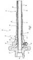
- Fig. 1is a provided with the general reference numeral 10 medical instrument for sucking and rinsing in two partial images shown.
- the upper part of the picture in Fig. 1shows a distal portion of the instrument 10, and the lower part of a subsequent to the distal portion proximal portion of the instrument 10th
- the instrument 10is used in surgical procedures, particularly in the context of minimally invasive surgery, for delivering irrigation fluid into a surgical field and for aspirating fluids and tissue remnants from the surgical field.
- the instrument 10allows for visual inspection through an endoscope, as will be described below.
- the instrument 10has an elongate shaft 12 having a distal end 14 and a proximal end 16 (see FIG. Fig. 2 ) having.
- the shaft 12has a first channel 18 which serves as a suction channel and which has a suction opening 20 corresponding to the distal end 14 of the shaft 12.
- the shaft 12also has a second channel 22 which is separate from the first channel 18 and which has a flushing opening 24 corresponding to the distal end 14 of the shaft 12.
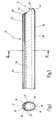
- the shaft 12has a cross-sectionally closed (see. Fig. 4 ) First tube 26, in which the first channel 18 (suction channel) is arranged.
- the shank 12also has a cross-sectionally open cross-section (cf. Fig. 4 ) second pipe 28, which with its open longitudinal side, here with its longitudinal edges 30 and 32 (see. Fig. 4 ), placed on a circumferentially limited outer side 34 of the first tube 26 and is attached to this sealing.
- the second channel 22 forming the flushing channel in the shaft 12is formed in the intermediate space between the outer side 34 of the first tube 26, on which the second tube 28 is placed, and an inner side 36 of the second tube 28.
- the second tube 28is sealed along its longitudinal edges 30 and 32 to the first tube 26 by a continuous laser weld.
- the cross section of the first tube 26is according to Fig. 4 not exactly round, but has in its side facing away from the second tube 28 on an oval bulge.
- the second tube 28is essentially formed of a full tube, here cylindrical tube, which is cut approximately half.
- the gap forming the second channel 22 between the outer side 34 of the first tube 26 and the inner side 36 of the second tube 28is formed sickle-shaped with a small peak height, so that the total cross section of the shaft 12 is only slightly larger than the cross section of the first tube 26 alone.
- the entire cross section of the shaft 12is according to Fig. 4 shaped like an oval.
- the first tube 26also has an in Fig. 2 and 4 with broken lines indicated third channel 38 into which an unillustrated optic shaft of an endoscope can be inserted, which then extends to the distal end 14 of the shaft 12.
- the further channel 38is not separated from the first channel 18, which forms the suction channel, by an intermediate wall.
- the suction channel 18is formed with inserted into the channel 38 optical shaft through the remaining gap between the optical shaft and the first tube 26, as seen from Fig. 2 to 4 evident.
- the second tube 28is placed on that outer side 34 of the first tube 26, which faces away from the suction channel forming the first channel 18 in the first tube 26.
- the first channel 18 and the second channel 22are thus diametrically opposite one another with respect to the further channel 38.
- the second tube 28slightly projects beyond the outer side 34 of the first tube 26 to which it is placed.
- a distal end 40 of the second tube 28, on which the flushing opening 24 is formed,is flanged toward the first tube 26.
- a distal end 42 of the first tube 26is flanged on the second tube 28 facing away from the outer side of the second tube 28 towards.
- the fixed connection of the shaft 12 with the connecting part 44is realized by means of a hardening adhesive 46, which fills substantially all the gaps between the inside of the connecting part 44 and the outside of the shaft 12, without being in the interior of the shaft 12, that is, in the Channel 22 still penetrate into the channel 18 and the channel 38.
- the adhesive 46seals the first channel 18 against the second channel 22 at its proximal end.
- the connecting part 44is at its proximal End closed with a lid 48 in which a bore 50 for insertion of the endoscope into the channel 38 is present.
- This bore 50is sealed with inserted endoscope against the endoscope.
- the endoscopeis inserted into this bore 50 and fastened by means of a so-called ten-turn coupling 65.
- a detent button 52is further provided, on which the handle 45 can be fixed to the connecting part 44.
- an inlet or outletis provided both for the first channel 18 forming the suction channel and for the second channel 22 forming the flushing channel.
- a lateral, here radial bore 54is present, which is aligned with a bore 56 in the connecting part 44.
- a bore 58is present, which is aligned with a bore 60 in the connecting part 44.
- the holes 58 and 60are formed radially here.
- connections 61, 63for connecting a suction and a flushing hose present, extending from these terminals 61, 63 by the handle 45 not shown channels, which in patch on the connecting part 44 handle 45 via valves not shown in the Holes 60 and 56 and thus open into the bores 58 and 54.
- the adhesive 46seals the edges of the bores 54 to 60.
- the instrument 10can be permanently sucked through the channel 18, while via the channel 22 at any time, the flushing via a valve, not shown on the hand valve can be switched on without the suction through the channel 18 must be interrupted.
- the first tube 26 and the second tube 28are provided.
- the second tube 28can be made of a full tube, here cylinder tube, by cutting along a half-plane, so that the second tube 28 has an open longitudinal side. With this open longitudinal side, the second tube 28 is then placed with the longitudinal edges 30 and 32 on the outside 34 of the first tube 26 and fixedly connected along the longitudinal edges 30 and 32 with the first tube 26 by laser welding. In this way, then the one-piece shaft 12 is completed.
- the lateral bore 58is still introduced into the second tube 28.
- the interconnected unit of first tube 26 and second tube 28is then connected to the connector 44.
- the connecting part 44is in the in Fig. 5 provided form.
- the connecting part 44is a one-piece rotary part, in the previously the lateral bore 60 and a longitudinal bore 62 has been introduced.
- this open end 68is closed before filling the adhesive 46 by means of a rapidly curing further adhesive which cures in a short time. This adhesive then remains after filling the adhesive 46 at the proximal open end 68 of the second tube 28th
- a plugis inserted with another adhesive which also cures in a short time.
- an adhesiveis used, which can be pulled off again to release the bore 58 later than access to the flushing passage 22.
- the adhesive 46may be multi-stepped into the connector 44 infuse, in which case the effect can be exploited that the adhesive first flows into small gaps, that is placed around the edge of the bore 58 and then the edge of the bore 58 against the connecting part 44 in the first step already seals so that the stepwise refilling of the adhesive 46, no adhesive can flow into the bore 58.
- the bore 58is preferably formed with a smaller diameter than the bore 60, whereby the insertion of the plug is facilitated in the bore 58.
- the bore 56 and the bore 54is finally introduced through the adhesive 46 in the gap 64 therethrough, so that the bore 54 and the bore 56 are automatically sealed against the connecting part 44.
- the adhesive 46completely seals the first channel 18 from the second channel 22 in the proximal region, so that a mixing of rinsing liquid and suction liquid by the adhesive 46 is reliably avoided.
- the lid 48is then fastened to the connecting part 44.
- the connecting part 44 and the shaft 12 including the lid 48then constitute a firmly connected one-piece unit.
Landscapes
- Health & Medical Sciences (AREA)
- Life Sciences & Earth Sciences (AREA)
- Surgery (AREA)
- Heart & Thoracic Surgery (AREA)
- General Health & Medical Sciences (AREA)
- Animal Behavior & Ethology (AREA)
- Engineering & Computer Science (AREA)
- Veterinary Medicine (AREA)
- Biomedical Technology (AREA)
- Public Health (AREA)
- Radiology & Medical Imaging (AREA)
- Optics & Photonics (AREA)
- Molecular Biology (AREA)
- Medical Informatics (AREA)
- Pathology (AREA)
- Physics & Mathematics (AREA)
- Biophysics (AREA)
- Nuclear Medicine, Radiotherapy & Molecular Imaging (AREA)
- Anesthesiology (AREA)
- Pulmonology (AREA)
- Vascular Medicine (AREA)
- Hematology (AREA)
- Oral & Maxillofacial Surgery (AREA)
- Endoscopes (AREA)
- Surgical Instruments (AREA)
Abstract
Description
Translated fromGermanDie Erfindung betrifft ein medizinisches Instrument zum Saugen und Spülen, mit einem lang erstreckten Schaft, der einen ersten Kanal, der als Saugkanal dient, und einen zweiten Kanal aufweist, der als Spülkanal dient, wobei der Schaft ein im Querschnitt geschlossenes erstes Rohr aufweist, in dem der eine der Kanäle vorhanden ist, wobei der Schaft ein über seine Länge im Querschnitt offenes zweites Rohr aufweist, das mit seiner offenen Längsseite auf eine Außenseite des ersten Rohrs aufgesetzt und an diesem dichtend befestigt ist, wobei der andere Kanal im Zwischenraum zwischen der Außenseite des ersten Rohrs und einer Innenseite des zweiten Rohrs ausgebildet ist, wobei ferner am proximalen Ende des Schafts ein den Schaft umgebendes Verbindungsteil zum Verbinden des Schafts mit einem Handgriff angeordnet ist.The invention relates to a medical instrument for sucking and rinsing, comprising an elongate shaft having a first channel serving as a suction channel and a second channel serving as a flushing channel, the shaft having a first tube closed in cross section, in FIG the one of the channels is present, wherein the shaft has a cross-sectionally open over its length second tube, which is placed with its open longitudinal side on an outer side of the first tube and sealingly attached thereto, the other channel in the space between the outside is formed of the first tube and an inner side of the second tube, wherein further at the proximal end of the shaft, a shaft surrounding the connecting part for connecting the shaft is arranged with a handle.
Die Erfindung betrifft ferner ein Verfahren zum Herstellen eines solchen medizinischen Instruments.The invention further relates to a method for producing such a medical instrument.
Ein Instrument der eingangs genannten Art ist aus dem Dokument
Ein solches Instrument wird im Rahmen der Chirurgie bei Eingriffen am menschlichen oder tierischen Körper dazu verwendet, das Operationsgebiet mit frischer Spülflüssigkeit zu spülen und die Spülflüssigkeit sowie Blut und Gewebereste wieder aus dem Operationsgebiet abzusaugen. Bei endoskopischen Eingriffen dient das Spülen außerdem der Aufrechterhaltung der freien Sicht durch ein Endoskop.Such an instrument is used in the context of surgery for interventions on the human or animal body to rinse the operating area with fresh rinsing liquid and to suck the rinsing fluid and blood and tissue remnants from the operating area again. For endoscopic surgery, irrigation also serves to maintain a clear view through an endoscope.
Um gleichzeitig saugen und spülen zu können, ist es erforderlich, daß ein solches Instrument einen Schaft aufweist, der zwei Kanäle besitzt, und zwar einen Saugkanal und einen Spülkanal. Da die frische Spülflüssigkeit sich mit der abgesaugten Flüssigkeit nicht vermischen sollte, bevor sie in den Operationsraum gelangt, ist es weiterhin erforderlich, daß der Spülkanal von dem Saugkanal so separiert ist, daß sich Spülflüssigkeit und abgesaugte Flüssigkeit nicht miteinander im Schaft vermischen.In order to simultaneously suck and rinse, it is necessary that such an instrument has a shaft which has two channels, namely a suction channel and a flushing channel. Since the fresh rinsing liquid should not mix with the aspirated liquid before it enters the operating room, it is further required that the flushing channel is separated from the suction channel so that rinsing liquid and extracted liquid do not mix with each other in the shaft.
Aus dem DE-Firmenprospekt der Firma Karl Storz GmbH & Co. KG, "STORZ Karl Storz-Endoskope", Band "Laparoskopie", 3. Ausgabe 2/99, Seite IS-ACC 5 A ist ferner ein Instrument bekannt, dessen Schaft für den Spülkanal ein erstes Rohr und für den Saugkanal ein zweites Rohr aufweist, wobei das den Spülkanal bildende erste Rohr in das den Saugkanal bildende zweite Rohr als Einsatz eingeschoben ist. Der Saugkanal wird entsprechend zwischen der Außenseite des den Spülkanal bildenden ersten Rohrs und der Innenseite des zweiten Rohrs gebildet. Der Schaft dieses Instruments ist somit aus zwei im wesentlichen nicht miteinander verbundenen Rohren zusammengesetzt, woraus verschiedene Nachteile resultieren können. Zum einen besitzen einzelne Rohre eine geringere Biegestabilität, und zum anderen müssen sie jeweils einzeln nach außen mit entsprechenden Dichtungsmaßnahmen abgedichtet werden, beispielsweise durch O-Ringe, die einem Verschleiß unterliegen. Die ineinandergeschobene Anordnung aus Spülrohr und Saugrohr hat darüber hinaus den Nachteil, daß in dem Saugrohr bzw. in dem dünnen Spülrohr kein Raum zur Einführung eines Endoskops verbleibt, wenn nicht der Querschnitt des Gesamtschaftes über Maßen groß gewählt wird, was jedoch im Rahmen der minimal-invasiven Chirurgie, die durch kleinste Inzisionen am Körper erfolgt, unerwünscht ist. Darüber hinaus ist vor der Anwendung des Instruments eine Montage und vor der Reinigung des Instruments eine Demontage der einzelnen Rohre erforderlich, was die Handhabung des Instruments erschwert.From the DE company brochure of the company Karl Storz GmbH & Co. KG, "STORZ Karl Storz endoscopes", volume "Laparoscopy", 3rd edition 2/99, page IS-ACC 5 A is also known an instrument whose shaft for the flushing channel having a first tube and the suction channel, a second tube, wherein the flushing channel forming the first tube is inserted into the suction channel forming the second tube as an insert. The suction channel is corresponding formed between the outside of the first tube forming the flushing channel and the inside of the second tube. The shaft of this instrument is thus composed of two substantially unconnected pipes, resulting in various disadvantages can result. On the one hand, individual tubes have a lower bending stability, and on the other hand, they must each be individually sealed to the outside with appropriate sealing measures, for example, by O-rings, which are subject to wear. The nested arrangement of flushing pipe and suction pipe also has the disadvantage that in the suction pipe or in the thin rinsing pipe no space for insertion of an endoscope remains, unless the cross section of the entire shaft is chosen to be large dimensions, but this is within the minimum. Invasive surgery, which is done by the smallest incisions on the body, is undesirable. In addition, prior to the application of the instrument assembly and prior to cleaning the instrument disassembly of the individual tubes is required, which complicates the handling of the instrument.
Aus dem Dokument
Ferner ist aus der
Der Erfindung liegt die Aufgabe zugrunde, ein medizinisches Instrument der eingangs genannten Art dahingehend zu verbessern, daß es technisch einfach und kostengünstig herstellbar ist, und daß zugleich eine Abdichtung des Saug- gegen den Spülkanal erreicht wird.The invention has for its object to improve a medical instrument of the type mentioned in that it is technically simple and inexpensive to produce, and that at the same time a sealing of the suction is achieved against the flushing channel.
Der Erfindung liegt ferner die Aufgabe zugrunde, ein Verfahren zur Herstellung eines solchen Instruments anzugeben.The invention is further based on the object of specifying a method for producing such an instrument.
Erfindungsgemäß wird die zuerst genannte Aufgabe hinsichtlich des eingangs genannten medizinischen Instruments dadurch gelöst, daß der Schaft in das Verbindungsteil mittels eines aushärtenden Klebstoffes eingeklebt ist, und daß der Klebstoff das erste Rohr und das zweite Rohr in deren proximalem Endbereich gegeneinander abdichtet, wobei ein proximales offenes Ende des zweiten Rohrs mittels desselben Klebstoffs oder eines weiteren Klebstoffs verschlossen ist.According to the invention, the first-mentioned object is achieved with respect to the medical instrument mentioned above in that the shaft is glued into the connecting part by means of a thermosetting adhesive, and that the adhesive seals the first tube and the second tube in the proximal end region against each other, wherein a proximal open End of the second tube is closed by the same adhesive or another adhesive.
Bei dem erfindungsgemäßen Instrument wird der Schaft nicht durch zwei einzelne Rohre gebildet, die ineinander eingesetzt und wieder voneinander getrennt werden können, sondern der Schaft des erfindungsgemäßen Instruments weist zur Ausbildung des einen der beiden Kanäle ein über seine Länge im Querschnitt offenes zweites Rohr auf, das von seiner offenen Längsseite auf eine Außenseite des ersten Rohrs aufgesetzt und an diesem dichtend befestigt ist. Auf diese Weise überspannt das zweite Rohr nur einen Teilumfang des ersten Rohres, wodurch der Gesamtquerschnitt des Schaftes zum einen gering gehalten wird, und zum anderen die Möglichkeit besteht, in das erste Rohr zusätzlich ein Endoskop einschieben zu können, da der Innenraum des ersten Rohres nunmehr frei bleibt. Das auf das erste Rohr aufgesetzte und mit diesem fest verbundene zweite Rohr erhöht darüber hinaus die Biegesteifigkeit der Gesamtanordnung aus Saug- und Spülrohr. Ein weiterer wesentlicher Vorteil des erfindungsgemäßen Instruments besteht darin, daß der Zugang zu dem ersten Rohr und der Zugang zu dem zweiten Rohr zum Einleiten bzw. Abführen von Flüssigkeit nicht durch das jeweils andere Rohr hindurch erfolgen muß, weil das zweite Rohr nur einen Teilumfang der Außenseite des ersten Rohres überdeckt, während der übrige Umfang des ersten Rohres frei bleibt. Auch die Herstellung des Schafts des erfindungsgemäßen Instruments ist wesentlich vereinfacht, da sich das zweite Rohr mit einfachen Fügeverfahren, wie beispielsweise Kleben, Löten oder Schweißen, leicht auf der Außenseite des ersten Rohres dauerhaft befestigen läßt.In the instrument according to the invention, the shaft is not formed by two individual tubes, which can be inserted into each other and again separated from each other, but the shaft of the instrument according to the invention has for training one of the two channels on its length in cross-section open second tube, which is placed from its open longitudinal side on an outer side of the first tube and secured thereto sealingly. In this way, the second tube spans only a part of the circumference of the first tube, whereby the overall cross-section of the shaft is kept low on the one hand, and on the other hand, it is possible to insert into the first tube in addition to an endoscope, since the interior of the first tube now remains free. The attached to the first pipe and firmly connected to this second tube also increases the flexural rigidity of the overall arrangement of suction and flushing pipe. Another important advantage of the instrument according to the invention is that the access to the first tube and the access to the second tube for introducing and discharging liquid must not be made through the other tube, because the second tube only a part of the outside circumference covered the first tube, while the remaining circumference of the first tube remains free. Also, the production of the shaft of the instrument according to the invention is substantially simplified, since the second tube can be easily attached by simple joining methods, such as gluing, soldering or welding, on the outside of the first tube permanently.
Am proximalen Ende des Schafts ist ein den Schaft umgebendes Verbindungsteil zum Verbinden des Schafts mit einem Handgriff angeordnet, wobei der Schaft in das Verbindungsteil mittels eines aushärtenden Klebstoffs eingeklebt ist.At the proximal end of the shaft a connecting part surrounding the shaft for connecting the shaft is arranged with a handle, wherein the shaft is glued into the connecting part by means of a hardening adhesive.
Hierbei ist von Vorteil, daß nicht nur der Schaft insgesamt einteilig ausgebildet ist, sondern auch die Anordnung aus dem Schaft und dem Verbindungsteil zum Verbinden des Schafts mit einem Handgriff ebenfalls einteilig ausgebildet ist, wodurch der Aufwand bei der Montage und bei der Demontage des Instruments weiter vereinfacht wird. Das Verbinden des Schafts mit dem Verbindungsteil mittels eines aushärtenden Klebstoffes hat den Vorteil, daß es herstellungstechnisch einfach und kostengünstig durchführbar ist, und daß darüber hinaus der Klebstoff etwaige Zwischenräume zwischen dem Verbindungsteil und dem Schaft ausfüllen und so das Verbindungsteil gegen die Außenseite des Schafts ohne weitere Maßnahmen ausreichend abdichten kann, so daß zwischen den Schaft und das Verbindungsteil keine Verunreinigungen oder dergleichen eindringen können.It is advantageous that not only the shaft is formed in one piece, but also the arrangement of the shaft and the connecting part for connecting the shaft with a handle is also integrally formed, whereby the effort during assembly and disassembly of the instrument is further simplified. The connection of the shaft to the connecting part by means of a thermosetting adhesive has the advantage that it is easy to manufacture and inexpensive to carry out manufacturing technology, and that moreover, the adhesive fill any gaps between the connecting part and the shaft and so the connecting part against the outside of the shaft without further Measures can adequately seal, so that no impurities or the like can penetrate between the shaft and the connecting part.
Dabei dichtet der Klebstoff das erste Rohr und das zweite Rohr in deren proximalen Endbereich gegeneinander ab.The adhesive seals the first tube and the second tube in their proximal end against each other.
Hierbei ist weiterhin von Vorteil, daß auf Dichtungsmaßnahmen wie das Vorsehen von O-Ringen vollständig verzichtet werden kann, um die beiden Rohre so gegeneinander abzudichten, daß sich die Spülflüssigkeit nicht mit der abgesaugten Flüssigkeit vermischen kann.It is furthermore advantageous that sealing measures such as the provision of O-rings can be completely dispensed with in order to seal the two tubes against each other so that the flushing liquid can not mix with the extracted liquid.
In einer bevorzugten Ausgestaltung ist der Zwischenraum zwischen der Außenseite des ersten Rohres und der Innenseite des zweiten Rohres sichelförmig mit geringer Scheitelhöhe ausgebildet.In a preferred embodiment, the intermediate space between the outside of the first tube and the inside of the second tube is designed sickle-shaped with a low peak height.
Hierbei ist von Vorteil, daß der Gesamtquerschnitt des Schafts durch das zweite Rohr über den Querschnitt des ersten Rohrs hinaus nur geringfügig vergrößert wird. Der im Querschnitt sichelförmige Zwischenraum zwischen der Außenseite des ersten Rohrs und der Innenseite des zweiten Rohrs eignet sich besonders für den Spülkanal, da in der Spülflüssigkeit keine festen Stoffe enthalten sind, die sich in den Ecken des sichelförmigen Querschnitts festsetzen können.It is advantageous that the total cross section of the shaft is only slightly increased by the second tube beyond the cross section of the first tube. The crescent-shaped intermediate space between the outside of the first tube and the inside of the second tube is particularly suitable for the flushing channel, as in the rinsing liquid no solid Contain substances that can accumulate in the corners of the crescent-shaped cross-section.
In einer weiteren bevorzugten Ausgestaltung weist das erste Rohr weiterhin einen dritten Kanal zur Aufnahme eines Optikschafts eines Endoskops auf, und das zweite Rohr ist auf derjenigen Außenseite des ersten Rohrs aufgesetzt, die von dem verbleibenden freien Querschnitt in dem ersten Rohr, der den ersten oder zweiten Kanal bildet, abgewandt ist.In a further preferred embodiment, the first tube further comprises a third channel for receiving an optic shaft of an endoscope, and the second tube is placed on the outside of the first tube, which is the remaining free cross section in the first tube, the first or second Channel forms, is averted.
Diese Anordnung des zweiten Rohres hat den Vorteil, daß die Spülflüssigkeit beim Austreten aus dem distalen Ende des einen Rohrs aufgrund der am distalen Ende des anderen Rohrs anliegenden Saugdruckes am distalen Ende des Optikschafts vorbeigeleitet wird, wodurch sichergestellt werden kann, daß die Sicht durch das Endoskop durch Blut oder Gewebereste nicht beeinträchtigt wird.This arrangement of the second tube has the advantage that the irrigation fluid, as it exits the distal end of one tube, is directed past the distal end of the optic shaft due to the suction pressure applied to the distal end of the other tube, thereby ensuring that vision through the endoscope is not affected by blood or tissue remnants.
In einer weiteren bevorzugten Ausgestaltung überragt das zweite Rohr in Längsrichtung geringfügig die Außenseite des ersten Rohrs, an der es aufgesetzt ist.In a further preferred embodiment, the second tube protrudes slightly beyond the outer side of the first tube on which it is placed in the longitudinal direction.
Durch diese Maßnahme kann die zuvor beschriebene Wirkung des Vorbeileitens der Spülflüssigkeit an dem lichteintrittsseitigen Ende des Endoskops noch verbessert werden.By this measure, the above-described effect of passing the rinsing liquid at the light entry end of the endoscope can be further improved.
In einer weiteren bevorzugten Ausgestaltung ist ein distales Ende des zweiten Rohrs zum ersten Rohr hin umgebördelt, und/oder ein distales Ende des ersten Rohrs ist auf der dem zweiten Rohr abgewandten Außenseite zum zweiten Rohr hin umgebördelt.In a further preferred refinement, a distal end of the second tube is flanged toward the first tube, and / or a distal end of the first tube is flanged toward the second tube on the outside facing away from the second tube.
Auch diese Maßnahmen tragen vorteilhafterweise zu einer verbesserten Umspülung des distalen Endes des Optikschafts des ggf. in das erste Rohr eingesetzten Endoskops bei, und auch die Saugwirkung des Instruments wird dadurch verbessert.These measures also advantageously contribute to an improved flushing of the distal end of the optic shaft of the endoscope possibly inserted in the first tube, and also the suction effect of the instrument is thereby improved.
In einer weiteren bevorzugten Ausgestaltung ist der Saugkanal im ersten Rohr und der Spülkanal im Zwischenraum zwischen der Außenseite des ersten Rohrs und der Innenseite des zweiten Rohrs angeordnet.In a further preferred embodiment, the suction channel in the first tube and the flushing channel in the intermediate space between the outside of the first tube and the inside of the second tube is arranged.
Diese Maßnahme ist insbesondere dann, wenn, wie in einer zuvor beschriebenen Ausgestaltung der Zwischenraum zwischen der Innenseite des zweiten Rohrs und der Außenseite des ersten Rohrs sichelförmig mit geringer Scheitelhöhe ist, besonders vorteilhaft, da für die Spülflüssigkeit ein geringerer Querschnitt erforderlich ist als für die abgesaugte Flüssigkeit, die auch feste Stoffe, insbesondere Gewebereste, enthalten kann, so daß der Querschnitt des Schafts mit kombiniertem Saug- und Spülkanal klein gehalten werden kann.This measure is particularly advantageous when, as in a previously described embodiment, the gap between the inside of the second tube and the outside of the first tube is sickle-shaped with a low peak height, it is particularly advantageous since a smaller cross-section is required for the rinsing liquid than for the aspirated Liquid, which may also contain solid substances, in particular tissue remnants, so that the cross-section of the shaft with combined suction and irrigation channel can be kept small.
In einer weiteren bevorzugten Ausgestaltung ist das zweite Rohr entlang seiner Längsränder mit der Außenseite des ersten Rohrs durch Kleben, Löten oder Schweißen fest verbunden.In a further preferred embodiment, the second tube is firmly connected along its longitudinal edges with the outside of the first tube by gluing, soldering or welding.
Wenn das zweite Rohr unmittelbar mit seinen Längsrändern mit dem ersten Rohr fest verbunden ist, hat dies den Vorteil, daß sich auf der Außenseite des ersten Rohrs im Bereich der Verbindung mit dem zweiten Rohr keine Ecken oder Nischen bilden, in denen sich Verunreinigungen ansammeln können. Auf diese Weise ist der Schaft des erfindungsgemäßen Instruments leicht zu reinigen. Etwaige Kanten werden dabei durch den Klebstoff, das Lot bzw. das Schweißmaterial ausgefüllt bzw. geglättet.When the second tube is directly connected with its longitudinal edges with the first tube, this has the advantage that form on the outside of the first tube in the region of the connection with the second tube no corners or niches in which contaminants can accumulate. In this way, the shaft of the instrument according to the invention is easy to clean. Any edges are filled or smoothed by the adhesive, the solder or the welding material.
Besonders bevorzugt ist es dabei, wenn das zweite Rohr entlang seiner Längsränder mit der Außenseite des ersten Rohrs durch Laserschweißen verbunden ist.It is particularly preferred if the second tube is connected along its longitudinal edges with the outside of the first tube by laser welding.
Die Verbindung des zweiten Rohrs mit dem ersten Rohr durch Laserschweißen hat den Vorteil, daß mittels Laserschweißen eine sehr exakte und dünne Schweißnaht gebildet werden kann, die einen ausreichenden Schutz gegen Korrosion und Verschmutzungen an der Verbindungsstelle zwischen dem ersten und dem zweiten Rohr bietet.The connection of the second tube to the first tube by laser welding has the advantage that by laser welding a very precise and thin weld can be formed, which provides adequate protection against corrosion and contamination at the junction between the first and the second tube.
Hinsichtlich des eingangs genannten Verfahrens zum Herstellen eines medizinischen Instruments zum Saugen und Spülen, das einen lang erstreckten Schaft aufweist, der einen ersten Kanal, der als Saugkanal dient, und einen zweiten Kanal aufweist, der als Spülkanal dient, wobei der Schaft ein erstes Rohr aufweist, in dem der eine der Kanäle angeordnet ist, wobei ein über seine Länge im Querschnitt offenes zweites Rohr mit seiner offenen Längsseite auf eine Außenseite des ersten Rohrs aufgesetzt und an diesem dichtend befestigt wird, derart, dass zwischen der Außenseite des ersten Rohrs und einer Innenseite des zweiten Rohrs ein in Längsrichtung durchgehender Zwischenraum verbleibt, wird die oben an zweiter Stelle genannte Aufgabe dadurch gelöst, daß die miteinander verbundene Einheit aus erstem Rohr und zweitem Rohr anschließend mit einem Verbindungsteil zum Verbinden des Schafts mit einem Handgriff verbunden wird, wobei in dem Verbindungsteil eine Längsbohrung vorhanden ist, oder in das Verbindungsteil vor dem Verbinden mit dem Schaft eine Längsbohrung eingebracht wird, in die der Schaft eingeführt und anschließend mittels eines Klebestoffes eingeklebt wird, so daß der Klebstoff das erste Rohr und das zweite Rohr in deren proximalen Endbereich gegeneinander abdichtet, wobei ein proximales offenes Ende des zweiten Rohrs mittels desselben Klebstoffes oder eines weiteren Klebstoffes verschlossen wird.With regard to the above-mentioned method for producing a medical instrument for suction and rinsing, which has an elongated shaft which has a first channel serving as a suction channel and a second channel serving as a flushing channel, wherein the shaft has a first tube in which one of the channels is arranged, wherein a cross-sectionally open over its length second tube is placed with its open longitudinal side on an outer side of the first tube and sealingly attached thereto, such that between the outside of the first tube and an inner side of the second tube remains a longitudinally continuous gap, the second object mentioned above is achieved in that the interconnected unit of first tube and second tube is then connected to a connecting part for connecting the shaft with a handle, wherein in the connecting part a longitudinal bore is present, or in the connector before joining to the shaft a longitudinal bore is introduced into which the shaft is inserted and then adhesively bonded so that the adhesive seals the first tube and the second tube against each other in their proximal end region, one proximal open end of the second tube by means of the same adhesive or another Adhesive is sealed.
Das erfindungsgemäße Herstellungsverfahren hat den Vorteil, daß sich das Instrument mit einem kombinierten Saug- und Spülkanal auf besonders einfache Weise schaffen läßt, indem lediglich das zweite, an einer Längsseite offene Rohr mit seiner offenen Längsseite auf eine Außenseite des ersten Rohrs aufgesetzt und an diesem dichtend befestigt werden muß.The manufacturing method according to the invention has the advantage that the instrument can be created with a combined suction and irrigation channel in a particularly simple manner by only the second, open on one longitudinal side tube with its open longitudinal side placed on an outer side of the first tube and sealing at this must be attached.
Die miteinander verbundene Einheit aus erstem Rohr und zweitem Rohr wird mit einem Verbindungsteil zum Verbinden des Schafts mit einem Handgriff verbunden.The interconnected unit of first tube and second tube is connected to a connecting part for connecting the shaft with a handle.
In dem Verbindungsteil ist eine Längsbohrung vorhanden oder in das Verbindungsteil wird vor dem Verbinden mit dem Schaft eine Längsbohrung eingebracht, in die der Schaft eingeführt und anschließend mittels eines Klebstoffes eingeklebt wird.In the connecting part, a longitudinal bore is present or in the connecting part, a longitudinal bore is introduced before connecting to the shaft, in which the shaft is inserted and then glued by means of an adhesive.
Es ist bevorzugt, wenn das zweite Rohr mit dem ersten Rohr durch Kleben, Löten oder Schweißen fest verbunden wird.It is preferred if the second tube is firmly connected to the first tube by gluing, soldering or welding.
Diese Verbindungstechniken sind allesamt leicht und kostengünstig durchführbar und ermöglichen eine dauerhafte mechanisch stabile und dichte Befestigung des zweiten Rohrs an dem ersten Rohr.These joining techniques are all easily and inexpensively feasible and allow a permanent mechanically stable and tight attachment of the second tube to the first tube.
Besonders bevorzugt ist es, wenn das zweite Rohr mit dem ersten Rohr durch Laserschweißen verbunden wird.It is particularly preferred if the second tube is connected to the first tube by laser welding.
Wie bereits oben erwähnt, hat Laserschweißen den Vorteil, daß die Schweißnaht ohne starken Materialauftrag sehr dünn und exakt hergestellt werden kann.As mentioned above, laser welding has the advantage that the weld can be made very thin and accurate without heavy material application.
In einer weiteren bevorzugten Ausgestaltung wird vor dem Verbinden des zweiten Rohrs mit dem ersten Rohr in das zweite Rohr eine seitliche Bohrung eingebracht.In a further preferred embodiment, a lateral bore is introduced into the second tube before connecting the second tube to the first tube.
Diese Maßnahme ist insbesondere dann vorteilhaft, wenn der Zwischenraum zwischen dem ersten Rohr und dem zweiten Rohr nur eine geringe Höhe aufweist, weil dann ein nachträgliches Einbringen der seitlichen Bohrung zu einer Beschädigung des ersten Rohrs führen könnte. Durch das vorherige Einbringen der seitlichen Bohrung wird eine solche Beschädigung des ersten Rohrs sicher vermieden.This measure is particularly advantageous if the intermediate space between the first tube and the second tube has only a small height, because then a subsequent introduction of the lateral bore could lead to damage of the first tube. By the prior introduction of the lateral bore such damage to the first tube is reliably avoided.
Es ist weiterhin bevorzugt, wenn als Klebstoff zum Einkleben des Schafts in das Verbindungsteil ein sich unter Wärmeeinwirkung zunächst verflüssigender und anschließend aushärtender Klebstoff verwendet wird.It is further preferred if the adhesive used for gluing the shaft in the connecting part is a first liquefying and subsequently hardening adhesive under the action of heat.
In einer weiteren bevorzugten Ausgestaltung wird die seitliche Bohrung in dem zweiten Rohr vor dem Einfügen des Klebstoffes mittels eines anschließend wieder abnehmbaren Stopfens verschlossen.In a further preferred embodiment, the lateral bore is closed in the second tube before the insertion of the adhesive by means of a subsequently removable plug.
Hierbei wird der Vorteil erzielt, daß ein Eindringen des Klebstoffes nach seiner Verflüssigung in den Zwischenraum zwischen der Außenseite des ersten Rohrs und der Innenseite des zweiten Rohrs vermieden wird.Here, the advantage is achieved that penetration of the adhesive after its liquefaction in the space between the outside of the first tube and the inside of the second tube is avoided.
Dabei wird vorzugsweise als Stopfen ein rasch aushärtender wieder abziehbarer weiterer Klebstoff verwendet.In this case, preferably used as a stopper a rapidly curing redetachable further adhesive.
Die Verwendung eines solchen Klebstoffs hat den Vorteil, daß er sich nach dem Aushärten wieder leicht entfernen läßt und daß die seitliche Bohrung in dem zweiten Rohr besonders rasch verschlossen werden kann, wodurch das Herstellungsverfahren zeitgünstig durchführbar ist.The use of such an adhesive has the advantage that it can be easily removed after curing and that the lateral bore in the second tube closed particularly quickly can be, whereby the manufacturing process is carried out in a timely manner.
In einer weiteren bevorzugten Ausgestaltung wird ein proximales offenes Ende des zweiten Rohrs vor dem Einbringen des Klebstoffes verschlossen.In a further preferred embodiment, a proximal open end of the second tube is closed prior to the introduction of the adhesive.
Hierbei ist von Vorteil, daß auch ein Eindringen des Klebstoffes zum Verbinden des Schaftes mit dem Verbindungsteil in das offene proximale Ende des zweiten Rohrs vermieden wird. Die Verwendung eines rasch aushärtenden Klebstoffs, der jedoch im Unterschied zu dem zuvor genannten abziehbaren Klebstoff nicht wieder abziehbar ist, hat den Vorteil, daß das proximale offene Ende des Zwischenraums wischen der Innenseite des zweiten Rohrs und der Außenseite des ersten Rohrs mit sehr geringem Zeitaufwand verschlossen werden kann.It is advantageous that also penetration of the adhesive for connecting the shaft with the connecting part is avoided in the open proximal end of the second tube. However, the use of a rapidly curing adhesive which, unlike the abovementioned peelable adhesive, is not peelable has the advantage that the proximal open end of the gap between the inside of the second tube and the outside of the first tube is closed in a very short time can be.
In einer weiteren bevorzugten Ausgestaltung wird nach dem Einkleben des Schafts in das Verbindungsteil in das erste Rohr an einer Stelle, die nicht von dem zweiten Rohr bedeckt ist, eine seitliche Bohrung durch den ausgehärteten Klebstoff hindurch eingebracht.In a further preferred embodiment, after gluing the shaft into the connecting part, a lateral bore through the hardened adhesive is introduced into the first tube at a point which is not covered by the second tube.
Hierbei ist von Vorteil, daß der Zugang zu dem ersten Rohr, der durch die seitliche Bohrung gebildet wird, bereits abgedichtet ist, ohne daß weitere Dichtungsmaßnahmen erforderlich werden, weil die seitliche Bohrung durch den ausgehärteten Klebstoff hindurch erfolgt.It is advantageous that the access to the first tube, which is formed by the lateral bore, is already sealed, without further sealing measures are required because the lateral bore is made through the cured adhesive therethrough.
Weitere Vorteile und Merkmale ergeben sich aus der nachfolgenden Beschreibung und der beigefügten Zeichnung.Further advantages and features will become apparent from the following description and the accompanying drawings.
Es versteht sich, daß die vorstehend genannten und nachstehend noch zu erläuternden Merkmale nicht nur in der jeweils angegebenen Kombination, sondern auch in anderen Kombinationen oder in Alleinstellung verwendbar sind, ohne den Rahmen der vorliegenden Erfindung zu verlassen.It is understood that the features mentioned above and those yet to be explained not only in the particular combination, but also in other combinations or alone, without departing from the scope of the present invention.
Ein Ausführungsbeispiel der Erfindung ist in der Zeichnung dargestellt und wird mit Bezug auf diese hiernach näher beschrieben. Es zeigen:
- Fig. 1
- ein medizinisches Instrument zum Saugen und Spülen in Seitenansicht in zwei Teilbildern;
- Fig. 2
- einen Längsschnitt durch das untere Teilbild des In- struments in
Fig. 1 ; - Fig. 3
- einen Längsschnitt durch das obere Teilbild des In- struments in
Fig. 1 ; - Fig. 4
- einen Schnitt entlang der Linie IV-IV in
Fig. 3 ; - Fig. 5
- ein Einzelteil des Instruments in
Fig. 1 in Allein- stellung im Längsschnitt; und - Fig. 6
- eine perspektivische Gesamtdarstellung des Instru- ments in
Fig. 1 mit einem Handgriff in gegenüberFig. 1 verkleinertem Maßstab, wobei der Handgriff in einer Stellung kurz vor dem Verrasten mit dem Verbindungs- teil des Schafts gezeigt ist.
- Fig. 1
- a medical instrument for sucking and rinsing in side view in two partial images;
- Fig. 2
- a longitudinal section through the lower partial image of the instrument in
Fig. 1 ; - Fig. 3
- a longitudinal section through the upper partial image of the instrument in
Fig. 1 ; - Fig. 4
- a section along the line IV-IV in
Fig. 3 ; - Fig. 5
- an item of the instrument in
Fig. 1 in single position in longitudinal section; and - Fig. 6
- an overall perspective view of the instrument in
Fig. 1 with a handle in oppositeFig. 1 reduced scale, wherein the handle is shown in a position shortly before locking with the connecting part of the shaft.
In
Das Instrument 10 wird bei chirurgischen Eingriffen, insbesondere im Rahmen der minimal-invasiven Chirurgie, zum Zuführen von Spülflüssigkeit in ein Operationsgebiet und zum Absaugen von Flüssigkeiten und Geweberesten aus dem Operationsgebiet verwendet. Darüber hinaus ermöglicht das Instrument 10 eine visuelle Kontrolle durch ein Endoskop, wie hiernach noch beschrieben wird.The
Das Instrument 10 weist einen lang erstreckten Schaft 12 auf, der ein distales Ende 14 und ein proximales Ende 16 (vgl.
Der Schaft 12 weist einen ersten Kanal 18 auf, der als Saugkanal dient und der am distalen Ende 14 des Schafts 12 entsprechend eine Saugöffnung 20 aufweist.The
Der Schaft 12 weist weiterhin einen zweiten Kanal 22 auf, der von dem ersten Kanal 18 getrennt ist und der am distalen Ende 14 des Schafts 12 entsprechend eine Spülöffnung 24 aufweist.The
Der Schaft 12 weist ein im Querschnitt geschlossenes (vgl.
Das zweite Rohr 28 ist entlang seiner Längsränder 30 und 32 mit dem ersten Rohr 26 durch eine durchgehende Laserschweißnaht dicht verbunden.The
Der Querschnitt des ersten Rohrs 26 ist gemäß
Das erste Rohr 26 weist weiterhin einen in
Das zweite Rohr 28 ist dabei auf derjenigen Außenseite 34 des ersten Rohrs 26 aufgesetzt, die von dem den Saugkanal bildenden ersten Kanal 18 im ersten Rohr 26 abgewandt ist. Der erste Kanal 18 und der zweite Kanal 22 liegen sich somit bezüglich des weiteren Kanals 38 diametral gegenüber.The
Wie insbesondere aus
Am proximalen Ende 16 des Schafts 12 ist ein den Schaft 12 umgebendes Verbindungsteil 44 zum Verbinden des Schafts 12 mit einem in
Im Bereich des Verbindungsteils 44 ist sowohl für den den Saugkanal bildenden ersten' Kanal 18 als auch für den den Spülkanal bildenden zweiten Kanal 22 jeweils ein Zu- bzw. Abgang vorgesehen. Dazu ist in dem ersten Rohr 26 auf seiner dem zweiten Rohr 28 abgewandten Seite eine seitliche, hier radiale Bohrung 54 vorhanden, die mit einer Bohrung 56 in dem Verbindungsteil 44 fluchtet. Entsprechend ist in dem zweiten Rohr 28 eine Bohrung 58 vorhanden, die mit einer Bohrung 60 in dem Verbindungsteil 44 fluchtet. Auch die Bohrungen 58 und 60 sind hier radial ausgebildet. An dem Handgriff 45 (
Mit dem Instrument 10 kann permanent durch den Kanal 18 gesaugt werden, während über den Kanal 22 zu jedem Zeitpunkt die Spülung über ein am nicht dargestellten Handgriff vorhandenes Ventil zugeschaltet werden kann, ohne daß die Saugung über den Kanal 18 dazu unterbrochen werden muß.With the
Nachfolgend wird nun ein Verfahren zum Herstellen des Instruments 10 näher beschrieben.Hereinafter, a method of manufacturing the
In einem ersten Schritt werden das erste Rohr 26 und das zweite Rohr 28 bereitgestellt. Das zweite Rohr 28 kann dabei aus einem Vollrohr, hier Zylinderrohr, durch Aufschneiden entlang einer Halbebene hergestellt werden, so daß das zweite Rohr 28 eine offene Längsseite aufweist. Mit dieser offenen Längsseite wird das zweite Rohr 28 dann mit den Längsrändern 30 und 32 auf die Außenseite 34 des ersten Rohrs 26 aufgesetzt und entlang der Längsränder 30 und 32 mit dem ersten Rohr 26 durch Laserschweißen fest verbunden. Auf diese Weise ist dann der einteilige Schaft 12 fertiggestellt.In a first step, the
Vor dem Befestigen des zweiten Rohrs 28 auf dem ersten Rohr 26 wird noch die seitliche Bohrung 58 in das zweite Rohr 28 eingebracht.Before fastening the
Die miteinander verbundene Einheit aus erstem Rohr 26 und zweitem Rohr 28 wird anschließend mit dem Verbindungsteil 44 verbunden. Das Verbindungsteil 44 wird dabei in der in
Nachdem der Schaft 12 in das Verbindungsteil 44 in die in
Um zu verhindern, daß dabei Klebstoff in das proximale offene Ende 68 des zweiten Kanals 22 eindringt, wird dieses offene Ende 68 vor dem Einfüllen des Klebstoffs 46 mittels eines rasch aushärtenden weiteren Klebstoffs verschlossen, der in kurzer Zeit aushärtet. Dieser Klebstoff verbleibt dann nach dem Einfüllen des Klebstoffs 46 am proximalen offenen Ende 68 des zweiten Rohrs 28.In order to prevent adhesive from penetrating into the proximal
Um des weiteren zu verhindern, daß der Klebstoff 46 über die Bohrung 58 in den zweiten Kanal 22 eindringt, wird vor dem Eingießen des Klebstoffs 46 in die Bohrung 58 ein Stopfen mit einem weiteren Klebstoff, der ebenfalls in kurzer Zeit aushärtet, eingesetzt. Hierbei wird ein Klebstoff verwendet, der sich wieder abziehen läßt, um die Bohrung 58 später als Zugang zu dem Spülkanal 22 freizugeben.To further prevent the adhesive 46 from entering the
Anstatt das proximale offene Ende 68 und die Bohrung 58 vor dem Eingießen des Klebstoffs 46 mittels eines weiteren Klebstoffs zu verschließen, kann auch in Erwägung gezogen werden, den Klebstoff 46 in mehreren Schritten in das Verbindungsteil 44 einzugießen, wobei dann der Effekt ausgenutzt werden kann, daß der Klebstoff zuerst in kleine Spalte fließt, d.h. sich um den Rand der Bohrung 58 plaziert und dann den Rand der Bohrung 58 gegen das Verbindungsteil 44 im ersten Schritt bereits abdichtet, so daß beim schrittweisen Nachgießen des Klebstoffs 46 kein Klebstoff in die Bohrung 58 einfließen kann.Instead of closing the proximal
Des weiteren wird bei der zuerst beschriebenen Vorgehensweise, bei der die Bohrung 58 mittels eines Stopfens verschlossen wird, die Bohrung 58 vorzugsweise mit einem kleineren Durchmesser ausgebildet als die Bohrung 60, wodurch das Einsetzen des Stopfens in die Bohrung 58 erleichtert wird.Further, in the first described approach, in which the
Nach dem Aushärten des vollständig eingefüllten Klebstoffs 46 in das Verbindungsteil 44 wird schließlich die Bohrung 56 und die Bohrung 54 durch den Klebstoff 46 in den Spalt 64 hindurch eingebracht, so daß die Bohrung 54 und die Bohrung 56 automatisch gegen das Verbindungsteil 44 abgedichtet sind. Der Klebstoff 46 dichtet den ersten Kanal 18 von dem zweiten Kanal 22 im proximalen Bereich vollständig ab, so daß eine Vermischung von Spülflüssigkeit und Saugflüssigkeit durch den Klebstoff 46 sicher vermieden wird.After curing of the fully filled adhesive 46 in the connecting
Im abschließenden Schritt wird dann der Deckel 48 an dem Verbindungsteil 44 befestigt. Das Verbindungsteil 44 und der Schaft 12 einschließlich des Deckels 48 stellen dann eine fest miteinander verbundene einteilige Einheit dar.In the final step, the
Claims (15)
- A medical instrument for suction and irrigation, comprising an elongate shaft (12) with a first channel (18) serving as suction channel and with a second channel (22) serving as irrigation channel, the shaft (12) having a first tube (26) which is closed in cross section and in which one of the channels (18, 22) is present, wherein the shaft (12) has a second tube (28) which is open in cross section along its length and is placed with its open lengthwise side on an outside face (34) of the first tube (26) and secured sealingly thereon, the other channel is formed in the space between the outside face (34) of the first tube (26) and an inside face (36) of the second tube (28), wherein a connection part (44) surrounding the shaft (12) and used to connect said shaft (12) to a handgrip is arranged at the proximal end (16) of the shaft (12),characterized in that said shaft (12) is bonded into the connection part (44) by means of a curing adhesive (46), and that the adhesive (46) seals off the first tube (26) and the second tube (28) from one another in their proximal end area, wherein a proximal open end (68) of the second tube (28) is closed by means of the same adhesive (46) or by means of another adhesive.
- The instrument of claim 1,characterized in that the space between the outside face (34) of the first tube (26) and the inside face (36) of the second tube (28) is designed in the shape of a crescent with a low height.
- The instrument of claim 1 or 2,characterized in that the first tube (26) also has a third channel (38) for receiving an optical shaft of an endoscope, and wherein the second tube (28) is placed on that outside face (34) of the first tube (26) directed away from the remaining free cross section in the first tube (26) which forms the first or second channel (18, 22).
- The instrument of any one of claims 1 through 3,characterized in that the second tube (28) protrudes slightly in the longitudinal direction beyond the outside face (34) of the first tube on which it is placed.
- The instrument of any one of claims 1 through 4,characterized in that a distal end of the second tube (28) is flanged in toward the first tube (26).
- The instrument of any one of claims 1 through 5,characterized in that a distal end of the first tube (26), on the outside face directed away from the second tube (28), is flanged in toward said second tube (28).
- The instrument of any one of claims 1 through 6,characterized in that the suction channel is arranged in the first tube (26) and the irrigation channel is arranged in the space between the outside face (34) of the first tube (26) and the inside face (36) of the second tube (28).
- The instrument of any one of claims 1 through 7,characterized in that the second tube (28) along its lengthwise edges (30, 32) is fixedly connected to the outside face (34) of the first tube (26) by adhesive bonding, soldering or welding.
- The instrument of claim 8,characterized in that the second tube (28) along its lengthwise edges (30, 32) is connected to the outside face of the first tube by laser welding.
- A method for producing a medical instrument for suction and irrigation, which instrument comprises an elongate shaft (12) with a first channel (18) serving as suction channel and with a second channel (22) serving as irrigation channel, the shaft (12) having a first tube (26) in which one of the channels (18, 22) is arranged, wherein a second tube (28) which is open in cross section along its length is placed with its open lengthwise side on an outside face (34) of the first tube (26) and is secured sealingly thereon in such a way that a space continuous in the longitudinal direction remains between the outside face (34) of the first tube (26) and an inside face (36) of the second tube (28),characterized in that the interconnected unit comprising the first tube (26) and the second tube (28) is subsequently connected to a connection part (44) for connecting the shaft (12) to a handgrip, wherein a longitudinal bore (62) is present in the connection part (44), or a longitudinal bore (62) is formed in the connection part (44) before connection to the shaft (12), into which bore (62) the shaft (12) is introduced and then bonded by means of an adhesive (46) so that the adhesive (46) seals off the first tube (26) and the second tube (28) from one another in their proximal end area, wherein a proximal open end (68) of the second tube (28) is closed by means of the same adhesive (46) or by means of another adhesive.
- The method of claim 10,characterized in that the second tube (28) is fixedly connected to the first tube (26) by adhesive bonding, soldering or welding.
- The method of claim 11,characterized in that the second tube (28) is connected to the first tube (26) by laser welding.
- The method of any one of claims 10 through 12,characterized in that, before the second tube (28) is connected to the first tube (26), a lateral bore (58) is formed in the second tube (28).
- The method of claim 13,characterized in that, before introduction of the adhesive (46), the lateral bore (58) in the second tube (28) is closed off by means of a subsequently removable stopper.
- The method of claim anyone of claims 10 through 14,characterized in that, after the shaft (12) has been bonded adhesively into the connection part (44), a lateral bore (54) is formed right through the cured adhesive (46) into the first tube (26) at a location not covered by the second tube (28).
Applications Claiming Priority (3)
| Application Number | Priority Date | Filing Date | Title |
|---|---|---|---|
| DE10245009 | 2002-09-20 | ||
| DE10245009ADE10245009B4 (en) | 2002-09-20 | 2002-09-20 | Medical instrument for sucking and rinsing and process for its preparation |
| PCT/EP2003/009025WO2004032733A1 (en) | 2002-09-20 | 2003-08-14 | Medical instrument for suction and cleaning and related method for making same |
Publications (2)
| Publication Number | Publication Date |
|---|---|
| EP1542579A1 EP1542579A1 (en) | 2005-06-22 |
| EP1542579B1true EP1542579B1 (en) | 2010-10-13 |
Family
ID=31984118
Family Applications (1)
| Application Number | Title | Priority Date | Filing Date |
|---|---|---|---|
| EP03747899AExpired - LifetimeEP1542579B1 (en) | 2002-09-20 | 2003-08-14 | Medical instrument for suction and cleaning and related method for making same |
Country Status (4)
| Country | Link |
|---|---|
| US (1) | US7857784B2 (en) |
| EP (1) | EP1542579B1 (en) |
| DE (2) | DE10245009B4 (en) |
| WO (1) | WO2004032733A1 (en) |
Cited By (1)
| Publication number | Priority date | Publication date | Assignee | Title |
|---|---|---|---|---|
| EP4151138A1 (en) | 2021-09-21 | 2023-03-22 | Karl Storz SE & Co. KG | External shaft for an endoscope and endoscope system |
Families Citing this family (29)
| Publication number | Priority date | Publication date | Assignee | Title |
|---|---|---|---|---|
| WO2003066124A2 (en)* | 2002-02-01 | 2003-08-14 | The Cleveland Clinic Foundation | Apparatus for facilitating delivery of at least one device to a target site in a body |
| DE10245009B4 (en) | 2002-09-20 | 2007-09-06 | Karl Storz Gmbh & Co. Kg | Medical instrument for sucking and rinsing and process for its preparation |
| JP2008145684A (en)* | 2006-12-08 | 2008-06-26 | Sony Corp | Optical waveguide and optical module |
| US8206349B2 (en) | 2007-03-01 | 2012-06-26 | Medtronic Xomed, Inc. | Systems and methods for biofilm removal, including a biofilm removal endoscope for use therewith |
| US9326665B2 (en) | 2007-01-09 | 2016-05-03 | Medtronic Xomed, Inc. | Surgical instrument, system, and method for biofilm removal |
| US20080167527A1 (en)* | 2007-01-09 | 2008-07-10 | Slenker Dale E | Surgical systems and methods for biofilm removal, including a sheath for use therewith |
| JP2008278968A (en)* | 2007-05-08 | 2008-11-20 | Fujinon Corp | Insertion assisting tool for endoscope |
| US8225787B2 (en)* | 2007-08-31 | 2012-07-24 | Wet Nose Technologies, Llc | Adjustable pressure device and system thereof |
| US8235042B2 (en)* | 2007-08-31 | 2012-08-07 | Wet Nose Technologies, Llc | Exhalatory pressure device and system thereof |
| US9427504B2 (en)* | 2007-09-01 | 2016-08-30 | Wet Nose Technologies, Llc | Medical apparatus for suction and combination irrigation and suction |
| US9827367B2 (en) | 2008-04-29 | 2017-11-28 | Medtronic Xomed, Inc. | Surgical instrument, system, and method for frontal sinus irrigation |
| US8783247B2 (en)* | 2009-02-04 | 2014-07-22 | Wet Nose Technologies, Llc. | Pressure release systems, apparatus and methods |
| JP2011200356A (en)* | 2010-03-25 | 2011-10-13 | Fujifilm Corp | Endoscope insertion auxiliary tool |
| JP2011200358A (en)* | 2010-03-25 | 2011-10-13 | Fujifilm Corp | Endoscope insertion aid |
| US8882680B2 (en) | 2011-12-02 | 2014-11-11 | Interscope, Inc. | Insertable endoscopic instrument for tissue removal |
| US9204868B2 (en) | 2011-12-02 | 2015-12-08 | Interscope, Inc. | Methods and apparatus for removing material from within a mammalian cavity using an insertable endoscopic instrument |
| US11076840B2 (en) | 2011-12-02 | 2021-08-03 | Interscope, Inc. | Surgical console, specimen receiver, and insertable endoscopic instrument for tissue removal |
| US9808146B2 (en)* | 2011-12-02 | 2017-11-07 | Interscope, Inc. | Endoscopic tool for debriding and removing polyps |
| USD855802S1 (en) | 2011-12-23 | 2019-08-06 | Interscope, Inc. | Disposable tool |
| US9700378B2 (en)* | 2013-04-26 | 2017-07-11 | Medtronic Xomed, Inc. | Endoscope lens cleaning device |
| TWI554295B (en)* | 2014-02-27 | 2016-10-21 | 梓源生技有限公司 | Overtube and irrigation kit |
| DE102016201905A1 (en)* | 2016-02-09 | 2017-08-10 | Olympus Winter & Ibe Gmbh | Surgical instrument and method of manufacturing a surgical instrument |
| US11076920B2 (en)* | 2018-01-16 | 2021-08-03 | Microendoscopic Spine Institute, LLC | Instrumentation and surgical method for image-guided microendoscopic decompression |
| US11032481B2 (en) | 2018-07-06 | 2021-06-08 | Medos International Sarl | Camera scope electronic variable prism |
| US11202014B2 (en) | 2018-07-06 | 2021-12-14 | Medos International Sari | Camera scope electronic variable angle of view |
| BR212022007502U2 (en)* | 2020-01-30 | 2022-08-23 | Renato De Abreu Igor | CONSTRUCTION PROVISION APPLIED IN RIGID ENDOSCOPE FOR CLEANING THE OBJECTIVE LENS DURING THE VIDEO-SURGICAL PROCEDURE |
| US12004724B2 (en) | 2021-05-06 | 2024-06-11 | Medtronic Xomed, Inc. | Endoscope cleaning system |
| US11844544B2 (en) | 2021-08-25 | 2023-12-19 | Medtronic Ps Medical, Inc. | Irrigation devices in debridement systems |
| USD1071149S1 (en)* | 2022-11-28 | 2025-04-15 | Stryker Corporation | Suction tool |
Family Cites Families (32)
| Publication number | Priority date | Publication date | Assignee | Title |
|---|---|---|---|---|
| US3788326A (en)* | 1970-07-29 | 1974-01-29 | H Jacobs | Distally perforated catheter for use in ventilating system |
| JPS5650930A (en)* | 1979-10-02 | 1981-05-08 | Asahi Glass Co Ltd | Rubber stopper for sealing |
| US4619643A (en)* | 1983-07-25 | 1986-10-28 | Bai Chao Liang | Catheter |
| US4607635A (en)* | 1984-09-27 | 1986-08-26 | Heyden Eugene L | Apparatus for intubation |
| US4732139A (en) | 1985-09-03 | 1988-03-22 | Olympus Optical Co., Ltd. | Endoscope with insertion having a plurality of insertion holes |
| FR2588744B1 (en)* | 1985-10-17 | 1990-05-25 | Hallez Jean Paul | DEVICE FOR EXPLORING CAVITIES AND ITS USE, PARTICULARLY IN UTERINE CAVITY |
| US4840173A (en)* | 1988-02-22 | 1989-06-20 | Porter Iii John W | Endotracheal tube combination |
| US6004291A (en)* | 1988-02-29 | 1999-12-21 | Scimed Life Systems, Inc. | Intravascular catheter with distal guide wire lumen and transition |
| US5146916A (en)* | 1990-01-05 | 1992-09-15 | Catalani Angelo S | Endotracheal tube incorporating a drug-irrigation device |
| US5374245A (en)* | 1990-01-10 | 1994-12-20 | Mahurkar; Sakharam D. | Reinforced multiple-lumen catheter and apparatus and method for making the same |
| US5306249A (en)* | 1990-01-12 | 1994-04-26 | Don Michel T Anthony | Method of treating body passage walls |
| US5217482A (en)* | 1990-08-28 | 1993-06-08 | Scimed Life Systems, Inc. | Balloon catheter with distal guide wire lumen |
| JPH06511409A (en)* | 1992-05-11 | 1994-12-22 | メディカル イノベイションズ コーポレイション | Improved biliary catheter |
| US5336178A (en)* | 1992-11-02 | 1994-08-09 | Localmed, Inc. | Intravascular catheter with infusion array |
| US5575756A (en)* | 1993-08-16 | 1996-11-19 | Olympus Optical Co., Ltd. | Endoscope apparatus |
| US5378230A (en)* | 1993-11-01 | 1995-01-03 | Mahurkar; Sakharam D. | Triple-lumen critical care catheter |
| US5487339A (en)* | 1994-02-02 | 1996-01-30 | Reeves Brothers, Inc. | Method for fastening a holding bar to a printing blanket |
| US5380276A (en)* | 1994-02-28 | 1995-01-10 | The Kendall Company | Dual lumen catheter and method of use |
| US5810767A (en)* | 1994-05-11 | 1998-09-22 | Localmed, Inc. | Method and apparatus for pressurized intraluminal drug delivery |
| US5672171A (en)* | 1994-06-30 | 1997-09-30 | American Medical Systems, Inc. | Apparatus and method for interstitial laser treatment |
| GB9520234D0 (en)* | 1995-10-04 | 1995-12-06 | Smiths Industries Plc | Tracheal tubes and systems |
| DE19633124B4 (en)* | 1995-11-20 | 2009-06-10 | Storz Endoskop Gmbh | Scraping or cutting instrument |
| WO1997018745A2 (en) | 1995-11-20 | 1997-05-29 | Storz Endoskop Gmbh | Shaving or cutting instrument |
| US5810776A (en)* | 1996-02-13 | 1998-09-22 | Imagyn Medical, Inc. | Method and apparatus for performing laparoscopy |
| US5709698A (en)* | 1996-02-26 | 1998-01-20 | Linvatec Corporation | Irrigating/aspirating shaver blade assembly |
| WO2000048505A1 (en)* | 1999-02-18 | 2000-08-24 | Karl Storz Gmbh & Co. Kg | Endoscope |
| US6234993B1 (en)* | 1999-11-04 | 2001-05-22 | Microsurgical Technology, Inc. | Low profile phaco handpiece |
| US6858019B2 (en)* | 2001-01-09 | 2005-02-22 | Rex Medical, L.P. | Dialysis catheter and methods of insertion |
| US20020177800A1 (en)* | 2001-04-16 | 2002-11-28 | Bagaoisan Celso J. | Aspiration catheters and method of use |
| US20030163082A1 (en)* | 2002-02-26 | 2003-08-28 | Mertens Steven P. | Lumen weld |
| DE10245009B4 (en) | 2002-09-20 | 2007-09-06 | Karl Storz Gmbh & Co. Kg | Medical instrument for sucking and rinsing and process for its preparation |
| DE10307903A1 (en)* | 2003-02-18 | 2004-09-02 | Karl Storz Gmbh & Co. Kg | Method for mounting an endoscope |
- 2002
- 2002-09-20DEDE10245009Apatent/DE10245009B4/ennot_activeExpired - Fee Related
- 2003
- 2003-08-14EPEP03747899Apatent/EP1542579B1/ennot_activeExpired - Lifetime
- 2003-08-14WOPCT/EP2003/009025patent/WO2004032733A1/enactiveApplication Filing
- 2003-08-14USUS11/083,536patent/US7857784B2/ennot_activeExpired - Fee Related
- 2003-08-14DEDE50313188Tpatent/DE50313188D1/ennot_activeExpired - Lifetime
Cited By (4)
| Publication number | Priority date | Publication date | Assignee | Title |
|---|---|---|---|---|
| EP4151138A1 (en) | 2021-09-21 | 2023-03-22 | Karl Storz SE & Co. KG | External shaft for an endoscope and endoscope system |
| DE102021124453A1 (en) | 2021-09-21 | 2023-03-23 | Karl Storz Se & Co. Kg | Outer sheath for an endoscope and endoscopy system |
| DE102021124453B4 (en) | 2021-09-21 | 2023-12-07 | Karl Storz Se & Co. Kg | Outer shaft for an endoscope and endoscopy system |
| US12336688B2 (en) | 2021-09-21 | 2025-06-24 | Karl Storz Se & Co. Kg | Outer shaft for an endoscope and endoscope system |
Also Published As
| Publication number | Publication date |
|---|---|
| DE10245009A1 (en) | 2004-04-08 |
| US20050182353A1 (en) | 2005-08-18 |
| WO2004032733A1 (en) | 2004-04-22 |
| DE10245009B4 (en) | 2007-09-06 |
| EP1542579A1 (en) | 2005-06-22 |
| US7857784B2 (en) | 2010-12-28 |
| DE50313188D1 (en) | 2010-11-25 |
Similar Documents
| Publication | Publication Date | Title |
|---|---|---|
| EP1542579B1 (en) | Medical instrument for suction and cleaning and related method for making same | |
| EP1620016B1 (en) | Coaxial cannula provided with a sealing element | |
| DE4034143C2 (en) | Arthroscopic cannula for pressure measurement | |
| DE2005167C3 (en) | Postoperative drainage tube | |
| DE69425034T2 (en) | SUCTION AND FLUSHING PROBE | |
| DE69821638T2 (en) | UNIVERSAL CATHETER | |
| DE19631677C1 (en) | Endoscopic device for perforating veins | |
| DE3615694A1 (en) | Percutaneous nephroscope with safety wire | |
| EP1754438A1 (en) | Endoscope, in particular duodendoscope for mother-baby- cholangioscopy | |
| CH702752A1 (en) | Coupling part of a drainage tube unit. | |
| DE1300635B (en) | Sterile line connection for the flow of transfusion or infusion fluids | |
| DE3702441C2 (en) | ||
| DE202019005985U1 (en) | Medical instrument for the directed introduction of a therapeutic substance into a cavity and tool therefor | |
| DE102013214944A1 (en) | sonotrode | |
| WO2019072988A1 (en) | WORK CHANNEL SEAL | |
| EP1637065A1 (en) | Endoscopic instrument | |
| EP3488758B1 (en) | Laryngoscope spatula and method for manufacturing a laryngoscope spatula | |
| EP0989881B1 (en) | Catheter insertion device with a system for liquid-tight clamping of the insertion lumen | |
| DE3942905C2 (en) | Endoscope, especially cystoscope urethroscope | |
| AT421U1 (en) | ADAPTER SLEEVE AND CATHETER SET WITH SUCH AN ADAPTER SLEEVE | |
| EP2124812B1 (en) | Medical handle piece in particular for dental medicine with two separate outlet openings for media | |
| EP2604171B1 (en) | Handle for a medical instrument | |
| DE102019124638A1 (en) | Stopcock with steam openings | |
| DE102021105353B4 (en) | Stopcock, housing of a stopcock and method for producing a housing of a stopcock | |
| EP3413775B1 (en) | Surgical instrument and method for producing a surgical instrument |
Legal Events
| Date | Code | Title | Description |
|---|---|---|---|
| PUAI | Public reference made under article 153(3) epc to a published international application that has entered the european phase | Free format text:ORIGINAL CODE: 0009012 | |
| 17P | Request for examination filed | Effective date:20050311 | |
| AK | Designated contracting states | Kind code of ref document:A1 Designated state(s):AT BE BG CH CY CZ DE DK EE ES FI FR GB GR HU IE IT LI LU MC NL PT RO SE SI SK TR | |
| RBV | Designated contracting states (corrected) | Designated state(s):DE FR GB IT | |
| GRAP | Despatch of communication of intention to grant a patent | Free format text:ORIGINAL CODE: EPIDOSNIGR1 | |
| GRAS | Grant fee paid | Free format text:ORIGINAL CODE: EPIDOSNIGR3 | |
| GRAA | (expected) grant | Free format text:ORIGINAL CODE: 0009210 | |
| AK | Designated contracting states | Kind code of ref document:B1 Designated state(s):DE FR GB IT | |
| REG | Reference to a national code | Ref country code:GB Ref legal event code:FG4D Free format text:NOT ENGLISH | |
| REF | Corresponds to: | Ref document number:50313188 Country of ref document:DE Date of ref document:20101125 Kind code of ref document:P | |
| PLBE | No opposition filed within time limit | Free format text:ORIGINAL CODE: 0009261 | |
| STAA | Information on the status of an ep patent application or granted ep patent | Free format text:STATUS: NO OPPOSITION FILED WITHIN TIME LIMIT | |
| 26N | No opposition filed | Effective date:20110714 | |
| REG | Reference to a national code | Ref country code:DE Ref legal event code:R097 Ref document number:50313188 Country of ref document:DE Effective date:20110714 | |
| REG | Reference to a national code | Ref country code:FR Ref legal event code:PLFP Year of fee payment:14 | |
| REG | Reference to a national code | Ref country code:FR Ref legal event code:PLFP Year of fee payment:15 | |
| REG | Reference to a national code | Ref country code:DE Ref legal event code:R081 Ref document number:50313188 Country of ref document:DE Owner name:KARL STORZ SE & CO. KG INTELLECTUAL PROPERTY, DE Free format text:FORMER OWNER: KARL STORZ GMBH & CO. KG, 78532 TUTTLINGEN, DE Ref country code:DE Ref legal event code:R082 Ref document number:50313188 Country of ref document:DE Representative=s name:WITTE, WELLER & PARTNER PATENTANWAELTE MBB, DE Ref country code:DE Ref legal event code:R081 Ref document number:50313188 Country of ref document:DE Owner name:KARL STORZ SE & CO. KG, DE Free format text:FORMER OWNER: KARL STORZ GMBH & CO. KG, 78532 TUTTLINGEN, DE | |
| REG | Reference to a national code | Ref country code:FR Ref legal event code:PLFP Year of fee payment:16 | |
| PGFP | Annual fee paid to national office [announced via postgrant information from national office to epo] | Ref country code:IT Payment date:20220720 Year of fee payment:20 Ref country code:GB Payment date:20220720 Year of fee payment:20 Ref country code:DE Payment date:20220616 Year of fee payment:20 | |
| PGFP | Annual fee paid to national office [announced via postgrant information from national office to epo] | Ref country code:FR Payment date:20220721 Year of fee payment:20 | |
| P01 | Opt-out of the competence of the unified patent court (upc) registered | Effective date:20230527 | |
| REG | Reference to a national code | Ref country code:DE Ref legal event code:R071 Ref document number:50313188 Country of ref document:DE | |
| REG | Reference to a national code | Ref country code:GB Ref legal event code:PE20 Expiry date:20230813 | |
| PG25 | Lapsed in a contracting state [announced via postgrant information from national office to epo] | Ref country code:GB Free format text:LAPSE BECAUSE OF EXPIRATION OF PROTECTION Effective date:20230813 |