EP1542009B1 - Method of detecting nucleic acid by using dna microarrays and nucleic acid detection apparatus - Google Patents
Method of detecting nucleic acid by using dna microarrays and nucleic acid detection apparatusDownload PDFInfo
- Publication number
- EP1542009B1 EP1542009B1EP02755911AEP02755911AEP1542009B1EP 1542009 B1EP1542009 B1EP 1542009B1EP 02755911 AEP02755911 AEP 02755911AEP 02755911 AEP02755911 AEP 02755911AEP 1542009 B1EP1542009 B1EP 1542009B1
- Authority
- EP
- European Patent Office
- Prior art keywords
- nucleic acid
- acid probe
- dna microarray
- field effect
- dna
- Prior art date
- Legal status (The legal status is an assumption and is not a legal conclusion. Google has not performed a legal analysis and makes no representation as to the accuracy of the status listed.)
- Expired - Lifetime
Links
Images


Classifications
- C—CHEMISTRY; METALLURGY
- C12—BIOCHEMISTRY; BEER; SPIRITS; WINE; VINEGAR; MICROBIOLOGY; ENZYMOLOGY; MUTATION OR GENETIC ENGINEERING
- C12Q—MEASURING OR TESTING PROCESSES INVOLVING ENZYMES, NUCLEIC ACIDS OR MICROORGANISMS; COMPOSITIONS OR TEST PAPERS THEREFOR; PROCESSES OF PREPARING SUCH COMPOSITIONS; CONDITION-RESPONSIVE CONTROL IN MICROBIOLOGICAL OR ENZYMOLOGICAL PROCESSES
- C12Q1/00—Measuring or testing processes involving enzymes, nucleic acids or microorganisms; Compositions therefor; Processes of preparing such compositions
- C12Q1/68—Measuring or testing processes involving enzymes, nucleic acids or microorganisms; Compositions therefor; Processes of preparing such compositions involving nucleic acids
- C12Q1/6813—Hybridisation assays
- C12Q1/6816—Hybridisation assays characterised by the detection means
- C12Q1/6825—Nucleic acid detection involving sensors
- C—CHEMISTRY; METALLURGY
- C12—BIOCHEMISTRY; BEER; SPIRITS; WINE; VINEGAR; MICROBIOLOGY; ENZYMOLOGY; MUTATION OR GENETIC ENGINEERING
- C12Q—MEASURING OR TESTING PROCESSES INVOLVING ENZYMES, NUCLEIC ACIDS OR MICROORGANISMS; COMPOSITIONS OR TEST PAPERS THEREFOR; PROCESSES OF PREPARING SUCH COMPOSITIONS; CONDITION-RESPONSIVE CONTROL IN MICROBIOLOGICAL OR ENZYMOLOGICAL PROCESSES
- C12Q1/00—Measuring or testing processes involving enzymes, nucleic acids or microorganisms; Compositions therefor; Processes of preparing such compositions
- C12Q1/68—Measuring or testing processes involving enzymes, nucleic acids or microorganisms; Compositions therefor; Processes of preparing such compositions involving nucleic acids
- C12Q1/6813—Hybridisation assays
- C12Q1/6834—Enzymatic or biochemical coupling of nucleic acids to a solid phase
- C12Q1/6837—Enzymatic or biochemical coupling of nucleic acids to a solid phase using probe arrays or probe chips
- G—PHYSICS
- G01—MEASURING; TESTING
- G01N—INVESTIGATING OR ANALYSING MATERIALS BY DETERMINING THEIR CHEMICAL OR PHYSICAL PROPERTIES
- G01N27/00—Investigating or analysing materials by the use of electric, electrochemical, or magnetic means
- G01N27/26—Investigating or analysing materials by the use of electric, electrochemical, or magnetic means by investigating electrochemical variables; by using electrolysis or electrophoresis
- G01N27/403—Cells and electrode assemblies
- G01N27/414—Ion-sensitive or chemical field-effect transistors, i.e. ISFETS or CHEMFETS
- G01N27/4145—Ion-sensitive or chemical field-effect transistors, i.e. ISFETS or CHEMFETS specially adapted for biomolecules, e.g. gate electrode with immobilised receptors
- G—PHYSICS
- G01—MEASURING; TESTING
- G01N—INVESTIGATING OR ANALYSING MATERIALS BY DETERMINING THEIR CHEMICAL OR PHYSICAL PROPERTIES
- G01N33/00—Investigating or analysing materials by specific methods not covered by groups G01N1/00 - G01N31/00
- G01N33/48—Biological material, e.g. blood, urine; Haemocytometers
- G01N33/50—Chemical analysis of biological material, e.g. blood, urine; Testing involving biospecific ligand binding methods; Immunological testing
- G01N33/53—Immunoassay; Biospecific binding assay; Materials therefor
- G01N33/543—Immunoassay; Biospecific binding assay; Materials therefor with an insoluble carrier for immobilising immunochemicals
- G01N33/54366—Apparatus specially adapted for solid-phase testing
- G01N33/54373—Apparatus specially adapted for solid-phase testing involving physiochemical end-point determination, e.g. wave-guides, FETS, gratings
- B—PERFORMING OPERATIONS; TRANSPORTING
- B01—PHYSICAL OR CHEMICAL PROCESSES OR APPARATUS IN GENERAL
- B01J—CHEMICAL OR PHYSICAL PROCESSES, e.g. CATALYSIS OR COLLOID CHEMISTRY; THEIR RELEVANT APPARATUS
- B01J2219/00—Chemical, physical or physico-chemical processes in general; Their relevant apparatus
- B01J2219/00274—Sequential or parallel reactions; Apparatus and devices for combinatorial chemistry or for making arrays; Chemical library technology
- B01J2219/00277—Apparatus
- B01J2219/00279—Features relating to reactor vessels
- B01J2219/00281—Individual reactor vessels
- B01J2219/00286—Reactor vessels with top and bottom openings
- B—PERFORMING OPERATIONS; TRANSPORTING
- B01—PHYSICAL OR CHEMICAL PROCESSES OR APPARATUS IN GENERAL
- B01J—CHEMICAL OR PHYSICAL PROCESSES, e.g. CATALYSIS OR COLLOID CHEMISTRY; THEIR RELEVANT APPARATUS
- B01J2219/00—Chemical, physical or physico-chemical processes in general; Their relevant apparatus
- B01J2219/00274—Sequential or parallel reactions; Apparatus and devices for combinatorial chemistry or for making arrays; Chemical library technology
- B01J2219/00277—Apparatus
- B01J2219/00497—Features relating to the solid phase supports
- B01J2219/00527—Sheets
- B—PERFORMING OPERATIONS; TRANSPORTING
- B01—PHYSICAL OR CHEMICAL PROCESSES OR APPARATUS IN GENERAL
- B01J—CHEMICAL OR PHYSICAL PROCESSES, e.g. CATALYSIS OR COLLOID CHEMISTRY; THEIR RELEVANT APPARATUS
- B01J2219/00—Chemical, physical or physico-chemical processes in general; Their relevant apparatus
- B01J2219/00274—Sequential or parallel reactions; Apparatus and devices for combinatorial chemistry or for making arrays; Chemical library technology
- B01J2219/00583—Features relative to the processes being carried out
- B01J2219/00585—Parallel processes
- B—PERFORMING OPERATIONS; TRANSPORTING
- B01—PHYSICAL OR CHEMICAL PROCESSES OR APPARATUS IN GENERAL
- B01J—CHEMICAL OR PHYSICAL PROCESSES, e.g. CATALYSIS OR COLLOID CHEMISTRY; THEIR RELEVANT APPARATUS
- B01J2219/00—Chemical, physical or physico-chemical processes in general; Their relevant apparatus
- B01J2219/00274—Sequential or parallel reactions; Apparatus and devices for combinatorial chemistry or for making arrays; Chemical library technology
- B01J2219/00583—Features relative to the processes being carried out
- B01J2219/00596—Solid-phase processes
- B—PERFORMING OPERATIONS; TRANSPORTING
- B01—PHYSICAL OR CHEMICAL PROCESSES OR APPARATUS IN GENERAL
- B01J—CHEMICAL OR PHYSICAL PROCESSES, e.g. CATALYSIS OR COLLOID CHEMISTRY; THEIR RELEVANT APPARATUS
- B01J2219/00—Chemical, physical or physico-chemical processes in general; Their relevant apparatus
- B01J2219/00274—Sequential or parallel reactions; Apparatus and devices for combinatorial chemistry or for making arrays; Chemical library technology
- B01J2219/00583—Features relative to the processes being carried out
- B01J2219/00603—Making arrays on substantially continuous surfaces
- B01J2219/00653—Making arrays on substantially continuous surfaces the compounds being bound to electrodes embedded in or on the solid supports
- B—PERFORMING OPERATIONS; TRANSPORTING
- B01—PHYSICAL OR CHEMICAL PROCESSES OR APPARATUS IN GENERAL
- B01J—CHEMICAL OR PHYSICAL PROCESSES, e.g. CATALYSIS OR COLLOID CHEMISTRY; THEIR RELEVANT APPARATUS
- B01J2219/00—Chemical, physical or physico-chemical processes in general; Their relevant apparatus
- B01J2219/00274—Sequential or parallel reactions; Apparatus and devices for combinatorial chemistry or for making arrays; Chemical library technology
- B01J2219/00583—Features relative to the processes being carried out
- B01J2219/00603—Making arrays on substantially continuous surfaces
- B01J2219/00659—Two-dimensional arrays
- B01J2219/00662—Two-dimensional arrays within two-dimensional arrays
- B—PERFORMING OPERATIONS; TRANSPORTING
- B01—PHYSICAL OR CHEMICAL PROCESSES OR APPARATUS IN GENERAL
- B01J—CHEMICAL OR PHYSICAL PROCESSES, e.g. CATALYSIS OR COLLOID CHEMISTRY; THEIR RELEVANT APPARATUS
- B01J2219/00—Chemical, physical or physico-chemical processes in general; Their relevant apparatus
- B01J2219/00274—Sequential or parallel reactions; Apparatus and devices for combinatorial chemistry or for making arrays; Chemical library technology
- B01J2219/00583—Features relative to the processes being carried out
- B01J2219/00603—Making arrays on substantially continuous surfaces
- B01J2219/00677—Ex-situ synthesis followed by deposition on the substrate
- B—PERFORMING OPERATIONS; TRANSPORTING
- B01—PHYSICAL OR CHEMICAL PROCESSES OR APPARATUS IN GENERAL
- B01J—CHEMICAL OR PHYSICAL PROCESSES, e.g. CATALYSIS OR COLLOID CHEMISTRY; THEIR RELEVANT APPARATUS
- B01J2219/00—Chemical, physical or physico-chemical processes in general; Their relevant apparatus
- B01J2219/00274—Sequential or parallel reactions; Apparatus and devices for combinatorial chemistry or for making arrays; Chemical library technology
- B01J2219/0068—Means for controlling the apparatus of the process
- B01J2219/00686—Automatic
- B01J2219/00689—Automatic using computers
- B—PERFORMING OPERATIONS; TRANSPORTING
- B01—PHYSICAL OR CHEMICAL PROCESSES OR APPARATUS IN GENERAL
- B01J—CHEMICAL OR PHYSICAL PROCESSES, e.g. CATALYSIS OR COLLOID CHEMISTRY; THEIR RELEVANT APPARATUS
- B01J2219/00—Chemical, physical or physico-chemical processes in general; Their relevant apparatus
- B01J2219/00274—Sequential or parallel reactions; Apparatus and devices for combinatorial chemistry or for making arrays; Chemical library technology
- B01J2219/00718—Type of compounds synthesised
- B01J2219/0072—Organic compounds
- B01J2219/00722—Nucleotides
Definitions
- the present inventionrelates to a method of detecting nucleic acid by using DNA microarrays, a nucleic acid detection apparatus, and the DNA microarrays that are used in the field of biotechnology such as genetic diagnosis, sequence analysis of DNA, or analysis of gene polymorphism, and particularly in the field of genetic testing.
- DNA chip or DNA microarrayAs a technology to perform the analysis of gene function and gene expression in a large scale and to develop it to genetic testing, DNA chip or DNA microarray (hereinafter, collectively called DNA microarray) has been developed by Affymetrix Inc., Nanogen Inc., and so on.
- DNA microarraysutilizes detection by fluorescence as a basic technique and requires a laser or complex optical system. Therefore, the system becomes large in size and expensive.
- US 2001/0034030 A1discloses a technology for detecting nucleic acids in a sample, with which the invention has the features recited in the pre-characterising first part of each independent claim in common.
- the documentdiscloses an array of elements having probes which bind to the nucleic acids of interest. The change of dielectric properties of the elements resulting from the binding is electronically detected. Switches made of field effect transistors are used to electrically address desired ones of the elements.
- the probes of different elementsmay bind to different nucleic acid sequences, but redundant elements for the same sequence may also be provided.
- US 2002/0098496 A1discloses a method for detecting the variants of polymorphic nucleic acids with a DNA array having probes selectively binding to the variants and probes with substitutions of nucleotides serving as internal controls. The array is scanned and the ratios of the responses for the different probes are taken as a quality measure.
- target genea single nucleotide polymorphism contained in a specified gene (hereinafter, referred to as target gene) is explained in application of the method of detecting nucleic acid according to the present invention.
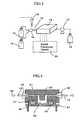
- Fig. 1represents a schematic perspective view of a DNA microarray 1 used in the present method
- Fig. 2represents a cross sectional view of an essential part of the DNA microarray 1.
- the DNA microarray 1comprises, as shown in Fig. 1 , a plurality of nucleic acid probe parts 2 arranged on a matrix and insulated gate field effect transistors 3 arranged so as to correspond to the plural probe parts 2.
- the plural nucleic acid probe parts 2are divided into two (called a first region 3a and a second region 3b, respectively).
- first polymorphismone polymorphism (hereinafter, sometimes called “first polymorphism”) of the target gene is detected, and in the second region 3b, the other polymorphism (hereinafter, sometimes called “second polymorphism”) of the target gene is detected.
- the nucleic acid probe part 2has a structure in which a nucleic acid probe 6 is immobilized on the surface of a gate insulator 5 of the insulated gate field effect transistor 4.
- the insulated gate field effect transistor 4is provided with, for example, a source 8 that serves as supply source of carrier and is arranged on a p-type silicon substrate 7, a drain 9 that takes out the carrier, and the gate insulator 5 that is placed on the p-type silicon substrate 7, the source 8, and the drain 9.
- the nucleic acid probe 6is an oligonucleotide, c-DNA, or branched DNA fragment that can hybridize to the target gene to be detected. It is desirable that the nucleic acid probe 6 is generally composed of 300 or less nucleotides, is able to hybridize to the target gene to be detected under an appropriate reaction condition, and in the case of oligonucleotide, is a nucleic acid fragment with a length of 80 or less nucleotides.
- the nucleic acid probe 6 in the first region 3ahas a sequence capable of hybridizing to the target gene of the first polymorphism and incapable of hybridizing to the target gene of the second polymorphism.
- the nucleic acid probe 6 in the second region 3bhas a sequence capable of hybridizing to the target gene of the second polymorphism and incapable of hybridizing to the target gene of the first polymorphism.
- a materialsuch as silicon dioxide (SiO 2 ), silicon nitride (SiN), aluminum oxide (Al 2 O 3 ), or tantalum oxide (Ta 2 O 5 ) is used alone or in combination, and that a bilayer structure in which silicon nitride (SiN), aluminum oxide (Al 2 O 3 ), and tantalum oxide (Ta 2 O 5 ) are layered on top of silicon dioxide (SiO 2 ) is generally employed to keep performance of a transistor better.
- silicon dioxideSiO 2
- SiNsilicon nitride
- Al 2 O 3aluminum oxide
- tantalum oxideTa 2 O 5
- one of the terminal ends of the nucleic acid probe 6may be chemically modified to have an amino group (NH 2 group), thiol group (SH group), biotin, or the like.
- the surface of the gate insulator 5is modified with aminopropylethoxysilane, polylysine, or the like to introduce amino groups on the surface of the insulating film, and then reacted with glutaraldehyde or phenylene diisocyanate (PDC) to immobilize the nucleic acid probe 6 that has been chemically modified to have an amino group on the surface of the gate insulator 5.
- PDCglutaraldehyde or phenylene diisocyanate
- nucleic acid probe 6 chemically modified to have a thiol groupWhen the nucleic acid probe 6 chemically modified to have a thiol group is immobilized on the surface of the gate insulator 5, a gold thin film is formed on the gate insulator 5, and the nucleic acid probe 6 is immobilized by taking advantage of an affinity between thiol group and gold. Furthermore, when the nucleic acid probe 6 chemically modified to have biotin is immobilized, streptoavidin is introduced onto the surface of the gate insulator 5, and the nucleic acid probe 6 is immobilized on the surface of the gate insulator 5 by taking advantage of an affinity between biotin and streptoavidin.
- a solution containing the nucleic acid probe 6is dropped or spotted only in a predetermined area on the surface of the gate insulator 5, thereby immobilizing the nucleic acid probe 6 only in a desired area on the gate insulator 5.
- the nucleic acid probe 6may be immobilized on the surface or in the inside of the fixed carrier in an indirect way.
- the materials that can be used for the fixed carrierinclude agarose, polyacrylamide, polyhydroxyethyl methacrylate (pHEMA), and the like.
- the fixed carriermay be chemically modified to have amino groups, streptoavidin, or the like, and as described above, the nucleic acid probe may be immobilized on the fixed carrier by using glutaraldehyde or PDC, or by taking advantage of an affinity with avidin, respectively. In this way, the nucleic acid probe 6 may also be immobilized indirectly on the gate insulator 5 of the insulated gate field effect transistor 4 via the fixed carrier.
- the target gene contained in the sample and the nucleic acid probe 6are allowed to hybridize to each other under an appropriate reaction condition. That is, a complex of either one of the nucleic acid probe 6 in the first area 3a and the nucleic acid probe 6 in the second area 3b with the target gene is formed depending on the polymorphism of the target gene contained in the sample, or complexes of both of the nucleic acid probe 6 in the first area 3a and the nucleic acid probe 6 in the second area 3b with the target gene are formed.
- nucleic acidsUnder an appropriate pH condition of a buffer solution that is used for hybridization of the sample to be examined, nucleic acids are charged negative. Accordingly, the complex formation between the nucleic acid probe 6 and the target gene induces a change in electric charge density in the vicinity of the gate insulator 5 of the insulated gate field effect transistor 4, thereby allowing the surface potential of the gate insulator 5 to be changed. This change behaves like a gate voltage change of a conventional insulated gate field effect transistor, resulting in a change of conductivity of the channel. Therefore, the complex formation in each nucleic acid probe part 2 can be detected as a change in drain current passing between the source 8 and the drain 9.
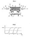
- a detection apparatus 10As shown in Fig. 3 can be used.
- the detection apparatus 10is provided with a flow cell 12 in which the DNA microarray 1 is placed, a flow channel 13 to supply various solutions to the flow cell 12, a hybridization solution 14 and a washing solution 15 that are connected to the leading end of the flow channel 13, a valve 16 that is provided on the flow channel 13 between the hybridization solution 14/the washing solution 15 and the flow cell 12 and used for switching the hybridization solution 14 and the washing solution 15, a pump 17 that controls the supply of each solution to the flow cell 12, a dispenser 18 that supplies a sample, an intercalator, and the like to the flow channel 13 via the valve 16, a waste bottle 19 that is connected to the terminal end of the flow channel 13, and a signal processing circuit 20 that processes and computes outputs from the DNA microarray 1 placed in the flow cell 12.
- the flow cell 12 shown in Fig. 4is provided with a housing 22 in which an internal flow channel 21 is formed, a printed circuit board 25 that is electrically connected to the DNA microarray 1 via wires 24 to serve as signal wires, pins 26 that connect electrically the printed circuit board 25 and the signal processing circuit 20, a protective cap 27 that separates the wires 24 from the internal flow channel 21, and bolts 28 that connect the internal flow channel 21 and the flow channel 13.
- Fig. 5is an exploded cross sectional view of the flow cell 12.
- the internal flow channel 21 in the housing 22is provided inside the housing by making, for example, a hole of one millimeter diameter, and makes contact with the DNA microarray 1 at the approximate center of the housing 22.
- the internal flow channel 21is in contact with at least the first region 3a and the second region 3b in the DNA microarray 1.
- the internal flow channel 21is connected to the flow channel 13 by attaching bolts 28 with the flow channel 13 inside to bolt-mounting portions 29 in the housing 22.
- the bolt-mounting portions 29 in the housing 22are threaded so as to be fitted with the bolts 28 to be attached.
- the end surface of the flow channel 13 that makes contact with the internal flow channel 21is treated so as to become flattened. By flattening the end surface of the flow channel 13 that makes contact with the internal flow channel 21, the flow channel 13 and the internal flow channel 21 can be kept in absolute contact with each other when the bolts 28 are screwed in, thereby preventing a solution from leaking.
- the printed circuit board 25is capable of detecting outputs from each of the plurality of the insulated gate field effect transistors 3 that correspond to a plurality of the nucleic acid probe parts 2, respectively, via the wires 24.
- the protective cap 26is made of, for example, acryl, polypropylene, polycarbonate, or the like, and provided between the housing 22 and the printed circuit board 25. The provision of the protective cap 26 between the housing 22 and the printed circuit board 25 prevents the wires 24 from being exposed to the internal flow channel 21.
- the detection apparatus 10constructed as described above makes it possible to identify polymorphisms of a target gene contained in a sample to be examined using the DNA microarray mounted in the flow cell 12. Specifically, first, the valve 16 is switched so as to supply only the hybridization solution 14 to the flow channel 13, and the pump 17 is driven. At the same time, the sample is supplied from the dispenser 18 to the flow channel 13 via the valve 16. This makes it possible to supply the hybridization solution 14 containing the sample to the flow channel 13 and the internal flow channel 21 in the flow cell 12, thereby allowing the sample to interact with the first region 3a and the second region 3b of the DNA microarray 1.
- the nucleic acid probe 6 having a nucleotide sequence complementary to the target gene contained in the sample and the target geneundergo hybridization reaction in the first region 3a or the second region 3b, or in both of the first region 3a and the second region 3b.
- the target gene contained in the samplehybridizes only to the nucleic acid probe 6 having a nucleotide sequence complementary to the target gene among the nucleic acid probes 6 contained in the first region 3a and the second region 3b.
- the solution supplied to the flow channel 13 and the internal flow channel 21is sent to the waste bottle 19 by the pump 17.
- the detection apparatus 10When the nucleic acid probe 6 and the target gene hybridize to each other (complex formation) in the detection apparatus 10, it is reflected as a change in drain current appearing in the insulated gate field effect transistors 3. In the detection apparatus 10, the change in drain current in the insulated gate field effect transistors 3 is detected by the printed circuit board, and signals are output to the signal processing circuit 20. Particularly, since the detection apparatus 10 is provided with plural nucleic acid probe parts 2, plural signals from each of the plural insulated gate field effect transistors 3 are output to the signal processing circuit 20.
- the plural nucleic acid probe parts 2bring about time differences in hybridization between the nucleic acid probe 6 and the target gene. This results in time differences in signal outputs from the plural insulated gate field effect transistors 4 as well. For example, signals from three insulated gate field effect transistors 4 are output at different times, respectively, as shown in Fig. 6 .
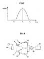
- the signal processing circuit 20measures time taken to reach a threshold level for each of the plural signals output at different times from the plural insulated gate field effect transistors 4, and determines the frequency distribution using time as the horizontal axis and the number of pieces of the nucleic acid probe parts 2 whose outputs have been measured to exceed the threshold level as the vertical axis.
- the signal processing circuit 20determines an average value in the frequency distribution obtained for the plural nucleic acid probe parts 2 as an output time.
- the signal processing circuit 20determines the output time T 3 as an average value (a maximum value in the normal distribution in this case) of the frequency distribution.
- the signal processing circuit 20is able to determine the output time for the plural nucleic acid probe parts 2 contained in the first region 3a and the output time for the plural nucleic acid probe parts 2 contained in the second region 3b.
- the detection apparatus 10is capable of judging the polymorphisms of the target gene based on each output time from the first region 3a and the second region 3b. That is, when the target gene is a homotype consisting only of a first polymorphism, the output time can be obtained only from the first region 3a. In contrast, when the target gene is a homotype consisting of only a second polymorphism, the output time can be obtained only from the second region 3b. Further, when the target gene is a heterotype consisting of the first polymorphism and the second polymorphism, the output time can be obtained from both of the first region 3a and the second region 3b. As described above, the polymorphism of the target gene can be judged from the output times from the first region 3a and the second region 3b using the detection apparatus 10.
- a measurement errorcan be made small compared to when the polymorphism is judged by a single nucleic acid probe part, thereby allowing more accurate judgment to be made.
- the detection apparatus 10allows the polymorphism of the target gene to be determined not only by obtaining the output time by the signal processing circuit 20 as described above, but also by the following way.
- the signal processing circuit 20computes proportions of the insulated gate field effect transistors 4 that have output signals after a predetermined elapsed time for each of the first region 3a and the second region 3b and compares them to each other. As the result, when the proportion for the first region 3a is larger compared to that for the second region 3b, the target gene can be judged to be a homotype consisting of only the first polymorphism.
- the target genewhen the proportion for the second region 3b is larger compared to that for the first region 3a, the target gene can be judged to be a homotype consisting of only the second polymorphism. Further, when the proportion for the first region 3a and that for the second region 3b are comparable, the target gene can be judged to be a heterotype consisting of the first polymorphism and the second polymorphism.
- the first polymorphism of interestmay be judged to be present at the time when an output from at least one nucleic acid probe part 2 among the nucleic acid probe parts 2 contained in the first region 3a has been obtained. This way of judging makes it possible to judge promptly whether or not the first polymorphism is contained in the sample.
- the detection apparatus 10may be provided with a reference electrode 30, a reference field effect transistor 31, and a differential measurement circuit 32 that measures a differential output between an output from the insulated gate field effect transistor 4 and an output from the reference field effect transistor 31.
- a nucleic acid 33 that does not contain a nucleotide sequence complementary to the target geneis immobilized on the surface of the gate insulator of the reference field effect transistor 31.
- the nucleic acid immobilized on the surface of the gate insulator of the reference field effect transistor 31does not hybridize to the target gene.
- the reference electrode 30is, for example, formed by dipping a silver-silver chloride electrode or a calomel electrode into an internal solution having a specified composition and concentration, and is provided at a place in contact with a solution supplied to the internal flow channel 21.
- the reference electrode 30may be provided, for example, inside the flow cell 21.
- a change in drain current of the insulated gate field effect transistor 4is detected as a surface potential by a drive circuit 34, and a change in drain current of the reference field effect transistor 31 is detected as a surface potential by a drive circuit 35.
- the differential measurement circuit 32measures the difference of the respective surface potentials of the drive circuit 34 and the drive circuit 35, and inputs the difference to the signal processing circuit 20 as a signal from the insulated gate field effect transistor 4.
- the reference field effect transistor 31 and the insulated gate field effect transistor 4are integrated on the same substrate. Integrating the reference field effect transistor 31 and the insulated gate field effect transistor 4 on the same substrate allows electric properties of the insulated gate field effect transistor 4 and the reference field effect transistor 31 to be uniformed.
- the detection apparatus 10does not require the same number of the reference field effect transistors 31 as that of the insulated gate field effect transistors 4. Since one reference field effect transistor 31 is used in common when outputs from the plural insulated gate field effect transistors 4 are obtained, provision of at least one reference field effect transistor 31 may suffice.
- the surface potentials of the reference field effect transistor 31 and the insulated gate field effect transistor 4can be stably measured by using the reference electrode 30 as a standard for the potential measurement.
- the detection apparatus 10it is also possible to quantify the target gene in the sample.
- the target gene in the sampleis quantified, similar measurements are performed with the use of plural samples containing known concentrations of the target gene in advance, and the output times are determined for these plural samples.
- the target gene contained in the sample to be measuredcan be quantified by comparing the output time of the measured sample to each output time of the plural samples.
- the output timeis measured by using the plural nucleic acid probe parts 2, and therefore, an error in quantitative determination arising from noise components, for example, due to non-specific hybridization of the target gene can be corrected. Accordingly, the target gene contained in the sample to be measured can be quantified with high accuracy by the detection apparatus 10.
- the detection apparatus 10may use the DNA microarray 1 provided with a first section consisting of the first region 3a and the second region 3b, a second section consisting of a third region 3c and a fourth region 3d, a third section consisting of a fifth region 3e and a sixth region 3f, and a fourth section consisting of a seventh region 3g and an eighth region 3h.
- the first region 3a to the eighth region 3hare provided with the plural nucleic acid probe parts 2, respectively.
- the nucleic acid probe 6 that hybridizes to the first polymorphism of the target geneis immobilized in the first region 3a, the third region 3c, the fifth region 3e, and the seventh region 3g.
- the nucleic acid probe 6 that hybridizes to the second polymorphism of the target geneis immobilized in the second region 3b, the fourth region 3d, the sixth region 3f, and the eighth region 3h.
- the time required for hybridization between the nucleic acid containing the target gene and the nucleic acid probes 6is adjusted so as to be mutually different in the first, second, third, and fourth sections. Specifically, the time required for hybridization in each section becomes different by making mutually different the immobilization densities of the nucleic acid probe 6 in the first section, the nucleic acid probe 6 in the second section, the nucleic acid probe 6 in the third section, and the nucleic acid probe 6 in the fourth section.
- the time required for hybridization in each sectionbecomes different by making different the areas of the nucleic acid probe parts 2 in the first section, the nucleic acid probe parts 2 in the second section, the nucleic acid probe parts 2 in the third section, and the nucleic acid probe parts 2 in the fourth section. Still further, the time required for hybridization in each section becomes different by making different the lengths (nucleotide lengths) of the nucleic acid probe 6 in the first section, the nucleic acid probe 6 in the second section, the nucleic acid probe 6 in the third section, and the nucleic acid probe 6 in the fourth section.
- the output timeis measured for each of the first to the fourth sections by the signal processing circuit 20. Since the time required for hybridization is different in the first to the fourth sections, it is possible to select an optimal section from the measured output times. In other words, when the time taken for hybridization between nucleic acid containing the target gene and the nucleic acid probe 6 is too short or too long, an error in quantifying the target gene becomes large. Accordingly, a highly accurate quantitative determination can be carried out by selecting an optimum section and measuring the output time using signals from the nucleic acid probe parts 2 contained in the selected section.
- the first polymorphismmay be judged to be present at the time when an output from at least one nucleic acid probe part 2 among the nucleic acid probe parts 2 contained in any one of the regions consisting of the first region 3a, the third region 3c, the fifth region 3e, and the seventh region 3g has been obtained.
- the DNA microarray 1 shown in Fig. 9it is possible to judge promptly whether or not the first polymorphism is contained in the sample.
- a system to detect whether or not a target gene is contained in a sampleis explained.
- a system to quantify the target geneis explained.
- a DNA microarray in which the 5' terminus of the nucleic acid probe 6 having a nucleotide sequence complementary to the target gene to be detected in the 3' terminal portion is immobilized on the surface of the gate insulator 2is used for the DNA microarray 1.
- a solution containing human chromosomes extracted from tissue pieces and white blood cellscan be used as a sample.
- nucleic acid amplificationis carried out on a plurality of the nucleic acid probe parts 2, respectively, using the immobilized nucleic acid probe 6 as a primer and a human chromosome contained in the sample of interest as a template, and the nucleic acid amplification is monitored by a plurality of the corresponding insulated gate field effect transistors 4.
- valve 16is switched first such that reagents necessary for the nucleic acid amplification can be supplied to the flow channel 13, and the pump 17 is driven.
- a solution containing human chromosomesis supplied from the dispenser 18 to the flow channel 13 via the valve 16. In this way, the solution containing human chromosomes and the reagents necessary for the nucleic acid amplification can be supplied to the flow channel 13 and the internal flow channel 21 of the flow cell 12.
- nucleic acid amplificationis carried out on the DNA microarray 1.
- the nucleic acid amplificationis performed using the nucleic acid probe 6 as a primer. That is, first as shown in Fig. 10A , hybridization (annealing) between the nucleic acid probe 6 and a portion of the target gene in the DNA fragment 38 takes place by controlling the gate insulator 2 to a predetermined temperature. Then, as shown in Fig.
- an extension reactionis carried out from the 3' terminus of the nucleic acid probe 6 using the DNA fragment 38 as the template with the aid of an enzyme (DNA polymerase, etc.) included in the reagents necessary for the nucleic acid amplification by controlling the gate insulator 2 to a predetermined temperature. Controlling the gate insulator 2 to a predetermined temperature after the extension reaction induces heat denaturation to allow the DNA fragment 38 to be dissociated. Then again, by controlling the gate insulator 2 to the predetermined temperature, hybridization (annealing) between the unreacted nucleic acid probe 6 and the portion of the target gene in the DNA fragment 38 takes place as shown in Fig. 10C . Subsequently, as shown in Fig.
- the extension reactiontakes place from the 3' terminus of the nucleic acid probe 6 using the DNA fragment 38 as the template with the aid of the enzyme (DNA polymerase, etc.) included in the reagents necessary for the nucleic acid amplification by controlling again the gate insulator 2 to the predetermined temperature.
- the enzymeDNA polymerase, etc.
- the extension reaction from the 3' terminus of the nucleic acid probe 6 using the DNA fragment 38 as the templateis carried out in turn by controlling the temperature of the gate insulator 2.
- the progress of the extension reaction in the nucleic acid probe part 2results in a change of charge density in the vicinity of the gate insulator 5 of the insulated gate field effect transistors 4 corresponding to the nucleic acid probe part 2, and the surface potential of the gate insulator 5 is changed.
- This changeacts like a gate voltage change in a conventional insulated gate field effect transistor, resulting in a change of electric conductivity of the channel. Therefore, the progress of the extension reaction in each nucleic acid probe part 2 can be detected as a change in drain current flowing between the source 8 and the drain 9 by using the detection apparatus 10.
- a measurement erroris minimized owing to the use of plural nucleic acid probe parts 2 when compared to the case in which the target gene is detected by a single nucleic acid probe part, thereby allowing the target gene to be accurately detected even when its amount present in a sample is small.
- the detection apparatus 10 described abovemakes it possible to quantify the target gene in the sample.
- the target gene in the sampleis quantified, a plurality of samples containing known concentrations of the target gene are measured beforehand in a similar way, and the output time is determined for each of these plural samples.
- the target gene contained in a sample to be measuredcan be quantified by comparing the output time of the measured sample and each output time of the plural samples.
- an error in the quantitative determinationfor example, due to noise components arising from non-specific hybridization of the target gene can be corrected since the output time is measured by using the plurality of the nucleic acid probe parts 2. Therefore, the target gene contained in the sample to be measured can be quantified by the detection apparatus 10 with high accuracy.
- nucleic acid probe 6with the 5' terminus modified to have an amino group was immobilized on the gate insulator 5 of the insulated gate field effect transistor 4 in order to examine the presence or absence of hepatitis B virus DNA.
- HBV probe (i)5'-GCG GAT CCG TGG AGT TAC TCT CGT TTT TGC-3'
- the nucleic acid 33may not be immobilized on the gate insulator of the reference field effect transistor 31, but may be modified to have an amino group on the 5' terminus.
- the sample usedwas Hepatitis B virus DNA extracted from serum that is available in a kit (Qiagen viral DNA kit).
- a sample solution containing the Hepatitis B virus DNA, IX PCR buffer (Mg 2+ plus) (product of Takara Co., Ltd.), 0.4 ⁇ M dNTP, and 5 units of Taq polymerase (Takara)was introduced into the flow cell 12 from the dispenser 18, and the gate insulator 5 was heated and cooled according to the following steps (1) to (3):
- double-stranded nucleic acidswere denatured to convert to single-stranded nucleic acids either by raising the temperature of the gate insulator 5 or introducing an alkaline solution into the flow cell 12 from the dispenser 18. Then, a washing solution was introduced into the flow cell 12 from the dispenser 18, thereby removing nucleic acids not immobilized on the substrate, unreacted nucleic acids, and various components from the DNA microarray 1. Subsequently, a buffer solution was introduced into the flow cell 12 from the dispenser 18, and output values from the insulated gate field effect transistors 4 were measured by the signal processing circuit 20.
- the output values from the signal processing circuit 20were the ones resulting from the single-stranded nucleic acids extended from the 3' terminus of the HBV probe (i) by the nucleic acid amplification, and the detection was made possible by a larger number of nucleotides compared with that of the nucleic acid 33 immobilized on the gate insulator of the reference field effect transistor 31.
- Fig. 11schematically depicts a state that single-stranded nucleic acids were extended from the nucleic acid probe 6 and the nucleic acid 33 immobilized on the gate insulator of the reference field effect transistor 31.
- the differential output of surface potential between the insulated gate field effect transistor 4 and the reference field effect transistor 31was 2.8 mV in the first specific example.
- the differential output measured in a similar mannerwas 0.4 mV. From these results, a significant difference between the sample containing Hepatitis B virus DNA and the sample not containing Hepatitis B virus DNA was obtained.
- the nucleic acid probe 6having a tendency to assume a higher order structure in accordance with the progress of the amplification reaction that takes place by the presence of the target gene in the sample was immobilized on the gate insulator 5 of the insulated gate field effect transistor 4 in order to detect the presence or absence of hepatitis B virus DNA with high sensitivity.
- the nucleic acid probe 6 used in the second specific examplehad a nucleotide sequence complementary to Hepatitis B virus DNA, with its 5' terminus being modified to have an amino group.
- the nucleic acid probe 6was as follows:
- the output valueswere the ones resulting from the single-stranded nucleic acids that extended from the 3' terminus of the HBV probe (ii) by the nucleic acid amplification and formed a higher order structure.
- the detectionwas made possible by a larger number of nucleotides compared with that of the nucleic acid 33 immobilized on the gate insulator of the reference field effect transistor 31 as well as by the difference in the higher order structure.
- Fig. 12schematically depicts a state that single-stranded nucleic acids were extended from the nucleic acid probe 6 and the nucleic acid 33 immobilized on the gate insulator of the reference field effect transistor 31.
- the 3' terminus of the nucleic acid probe 6assumes a higher order structure, i.e. a stem structure or a loop structure in this case, as the result of the progress of the extension reaction, as shown in Fig. 12 .
- This stem structureis formed because the single-stranded nucleic acid synthesized by the extension reaction is complementary to the HBV probe (ii) from its 5' terminus up to the 30 nucleotides.
- the loop structureis formed by the 19 nucleotides of the HBV probe (ii) on its 3' terminal side.
- the differential output of surface potential between the insulated gate field effect transistor 4 and the reference field effect transistor 31was 4.8 mV in the second specific example.
- the differential output measured in a similar mannerwas 0.5 mV. From these results, a significant difference between the sample containing Hepatitis B virus DNA and the sample not containing Hepatitis B virus DNA was obtained. Furthermore, since the nucleic acid probe 6 formed a higher order structure as the result of the extension reaction in the second specific example, the output value was obtained with higher sensitivity compared with that in the first specific example.
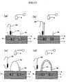
- nucleic acid probes 6 modified to have an amino group at the 5' terminuswere immobilized on the gate insulator 5 of the insulated gate field effect transistor 4 in order to detect the presence or absence of hepatitis B virus DNA with two kinds of the probes:
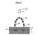
- Figs. 13A to 13Dillustrate the nucleic acid amplification in the third specific example.
- the HBV probe (i)is denoted by a nucleic acid probe 6a and the HBV probe (iii) is denoted by a nucleic acid probe 6b.
- hybridizationannealing
- an extension reactionwas carried out from the 3' terminus of the nucleic acid probe 6a using the DNA fragment 38 as the template with the aid of an enzyme (DNA polymerase, etc.) included in the reagents necessary for nucleic acid amplification by controlling the gate insulator 2 to the second predetermined temperature. Controlling the gate insulator 2 to the third temperature induced heat denaturation to allow the DNA fragment 38 to be dissociated, and a portion of the region that extended from the 3' terminus of the nucleic acid probe 6a hybridized (annealed) to the nucleic acid probe 6b as shown in Fig. 13C .
- an enzymeDNA polymerase, etc.
- the buffer solutionwas introduced from the dispenser 18 into the flow channel 13 through the valve 16 to remove the unreacted sample and the like on the DNA microarray 1.
- a solution containing an intercalator 39such as ethidium bromide or Hoechst 33258 was introduced from the dispenser 18 into the flow channel 13 through the valve 16, thereby inserting the intercalator 39 into the double stranded nucleic acid of the nucleic acid probe 6a and the nucleic acid probe 6b.
- the intercalator 39reacts only with the double stranded nucleic acid to bind, and does not bind to single stranded nucleic acids.
- an output valuewas measured by the signal processing circuit 20 in a manner similar to that in the first specific example.
- the differential outputwas 5.6 mV when the sample containing hepatitis B virus DNA was used.
- the differential outputwas 0.4 mV when the sample not containing hepatitis B virus DNA was used.
- a significant difference between the sample containing hepatitis B virus DNA and the sample not containing hepatitis B virus DNAwas also obtained in the third specific example.
- the differential outputwas 2.2 mV when measured in the state of the double stranded nucleic acid without using the intercalator 39 as shown in Fig. 13D . This result indicates that about twofold higher sensitivity could be achieved by the effect of the solution containing the intercalator 39 due to charge originating from the intercalator 39.
- nucleic acid probes 6 modified to have an amino group at the 5' terminuswere immobilized on the gate insulator 5 of the insulated gate field effect transistor 4 in order to detect the presence or absence of hepatitis B virus DNA using two kinds of the probes and a DNA polymerase with strand displacement activity:
- one hundred microliter of a sample solution containing hepatitis B virus DNA, 0.1 mM dNTP, 0.5 mM MgCl 2 , and 32 units of Bst polymerase (product of New England BioLabs Inc.)was introduced from the dispenser 18 into the flow cell 12, and the gate insulator 5 was incubated at 65°C to subject to an isothermal amplification reaction.
- This isothermal amplification reactionproceeds in a manner similar to that shown in Figs. 10A to 10D .
- the output valuewas measured by the signal processing circuit 20 after inserting the intercalator 39 into the nucleic acid double strand in a manner similar to that in the third specific example.
- the differential outputwas 5.8 mV when the sample containing hepatitis B virus DNA was used.
- the differential outputwas 0.3 mV when the sample not containing hepatitis B virus DNA was used.
- the differential outputwas 2.4 mV when the output value was measured in the state without using the intercalator 39. This result indicated that about twofold higher sensitivity could be achieved by the effect of the solution containing the intercalator 39.
- the target nucleic acidcan be detected as well as quantified by monitoring the outputs from a plurality of the nucleic acid probe parts to determine distribution per unit time with respect to the number of pieces of the nucleic acid probe parts whose outputs exceed a predetermined value.
- the target nucleic acidcan be detected with high accuracy as well as can be quantified with high accuracy.
Landscapes
- Life Sciences & Earth Sciences (AREA)
- Chemical & Material Sciences (AREA)
- Health & Medical Sciences (AREA)
- Engineering & Computer Science (AREA)
- Immunology (AREA)
- Organic Chemistry (AREA)
- Molecular Biology (AREA)
- Analytical Chemistry (AREA)
- Physics & Mathematics (AREA)
- General Health & Medical Sciences (AREA)
- Proteomics, Peptides & Aminoacids (AREA)
- Wood Science & Technology (AREA)
- Zoology (AREA)
- Biochemistry (AREA)
- Microbiology (AREA)
- Biotechnology (AREA)
- Bioinformatics & Cheminformatics (AREA)
- General Engineering & Computer Science (AREA)
- Biophysics (AREA)
- Genetics & Genomics (AREA)
- Biomedical Technology (AREA)
- Pathology (AREA)
- Hematology (AREA)
- Urology & Nephrology (AREA)
- General Physics & Mathematics (AREA)
- Medicinal Chemistry (AREA)
- Food Science & Technology (AREA)
- Cell Biology (AREA)
- Spectroscopy & Molecular Physics (AREA)
- Microelectronics & Electronic Packaging (AREA)
- Chemical Kinetics & Catalysis (AREA)
- Electrochemistry (AREA)
- Apparatus Associated With Microorganisms And Enzymes (AREA)
- Measuring Or Testing Involving Enzymes Or Micro-Organisms (AREA)
Description
- The present invention relates to a method of detecting nucleic acid by using DNA microarrays, a nucleic acid detection apparatus, and the DNA microarrays that are used in the field of biotechnology such as genetic diagnosis, sequence analysis of DNA, or analysis of gene polymorphism, and particularly in the field of genetic testing.
- Rapid progress has been made in the projects of genome sequence analysis for various living organisms including the human genome project, and enormous amounts of information on the nucleotide sequences are being accumulated. At present, the entire nucleotide sequence of the human genome is being determined. From now on, elucidation of gene functions in vivo seems likely to promote dramatic developments of gene-related technologies in a wide range of fields including diagnosis of various diseases, pharmaceutical development, breeding of agricultural products, and the like. The foundation for the progress in these new fields is formed by information about gene expression and gene function in addition to information on nucleotide sequences. As a technology to perform the analysis of gene function and gene expression in a large scale and to develop it to genetic testing, DNA chip or DNA microarray (hereinafter, collectively called DNA microarray) has been developed by Affymetrix Inc., Nanogen Inc., and so on. The majority of the present DNA microarrays utilizes detection by fluorescence as a basic technique and requires a laser or complex optical system. Therefore, the system becomes large in size and expensive.
- Furthermore, DNA microarrays developed currently detect the presence or absence of genes in a sample. On the other hand, there are few DNA microarrays that allow genes in a sample to be quantified.
US 2001/0034030 A1 discloses a technology for detecting nucleic acids in a sample, with which the invention has the features recited in the pre-characterising first part of each independent claim in common. The document discloses an array of elements having probes which bind to the nucleic acids of interest. The change of dielectric properties of the elements resulting from the binding is electronically detected. Switches made of field effect transistors are used to electrically address desired ones of the elements. The probes of different elements may bind to different nucleic acid sequences, but redundant elements for the same sequence may also be provided.US 2002/0098496 A1 discloses a method for detecting the variants of polymorphic nucleic acids with a DNA array having probes selectively binding to the variants and probes with substitutions of nucleotides serving as internal controls. The array is scanned and the ratios of the responses for the different probes are taken as a quality measure.- It is an object of the invention to provide an apparatus and a method for detecting a nucleic acid by use of a DNA microarray, which allow a specific nucleic acid contained in a sample to be quantified with high accuracy.
- This object is solved by the method of claim 1 and the apparatus of
claim 5. The dependent claims relate to preferred embodiments of the invention. - Embodiments of the present invention include the following:
- 1) A method of detecting nucleic acid by using DNA microarrays comprises the steps of allowing a sample containing nucleic acids to interact with a DNA microarray comprising a plurality of nucleic acid probe parts having a nucleic acid probe capable of hybridizing to a specific nucleic acid; monitoring outputs from each of the plurality of nucleic acid probe parts due to hybridization between the nucleic acid probe and the specific nucleic acid to determine frequency distribution of times when the outputs exceed a predetermined value with respect to each of the plurality of nucleic acid probe parts; and quantifying the specific nucleic acid contained in the sample based on an average value determined from the frequency distribution obtained in the above step.
- 2) The DNA microarray is formed by immobilizing the nucleic acid probe on the surface of gate insulator directly or via a carrier and comprises a plurality of insulated gate field effect transistors corresponding to the plurality of nucleic acid probe parts; and outputs from the insulated gate field effect transistors are monitored.
- 3) In the step of allowing the sample containing nucleic acids to interact with the DNA microarray, nucleic acid amplification is carried out on the DNA microarray using the nucleic acid as a template.
- 4) The nucleic acid amplification is carried out by an isothermal amplification method.
- 5) A nucleic acid detection apparatus comprises a measuring unit to attach a DNA microarray comprising a plurality of nucleic acid probe parts having a nucleic acid probe capable of hybridizing to a specific nucleic acid; detecting units that detect outputs from each of the nucleic acid probe parts of the DNA microarray attached on the measuring unit; and a computing unit that determines frequency distribution of times when the outputs detected by the detecting units exceed a predetermined value with respect to each of the plurality of nucleic acid probe parts and quantifies the specific nucleic acid contained in a sample based on an average value determined from the frequency distribution.
- 6) The DNA microarray is formed by immobilizing the nucleic acid probe on the surface of gate insulator directly or via a carrier and comprises a plurality of insulated gate field effect transistors corresponding to the plurality of nucleic acid probe parts; and the detecting units monitor outputs from the insulated gate field effect transistors.
- 7) The DNA microarray comprises a plurality of sections having the plurality of nucleic acid probe parts; and time taken for hybridization between the specific nucleic acid and the nucleic acid probe is different in each section.
- 8) A DNA microarray comprises a plurality of nucleic acid probe parts comprising a nucleic acid probe capable of hybridizing to a specific nucleic acid.
- 9) The DNA microarray comprises detecting units that are arranged so as to correspond to the plurality of nucleic acid probe parts and detect hybridization between the specific nucleic acid and the nucleic acid probe.
- 10) The detecting units are insulated gate field effect transistors.
- 11) The DNA microarray comprises a plurality of sections having the plurality of nucleic acid probe parts, wherein time required for hybridization between the specific nucleic acid and the nucleic acid probe is different in each of the plurality of sections.
- 12) The DNA microarray comprises the plurality of sections having the plurality of nucleic acid probe parts, wherein a density of the nucleic acid probe in the nucleic acid probe part differs in each of the plurality of sections.
- 13) The DNA microarray comprises the plurality of sections having the plurality of nucleic acid probe parts, wherein an area of the nucleic acid probe part differs in each of the plurality of sections.
- 14) The DNA microarray comprises the plurality of sections having the plurality of nucleic acid probe parts, wherein a length of the nucleic acid probe differs in each of the plurality of sections.
Fig. 1 is a schematic perspective view of a DNA microarray to which the present invention is applied;Fig. 2 is a cross sectional view of an essential part of the DNA microarray;Fig. 3 is a schematic structure showing a nucleic acid detection apparatus to which the present invention is applied;Fig. 4 is a cross sectional view of an essential part of a flow cell;Fig. 5 is an exploded cross sectional view of the essential part of the flow cell;Fig. 6 is a characteristic diagram showing outputs from a plurality of nucleic acid probe parts;Fig. 7 is a characteristic diagram showing a result after processing by a signal processing circuit based on the outputs from the plurality of nucleic acid probe parts;Fig. 8 is a circuit diagram showing a case where the outputs from the plurality of nucleic acid probe parts are measured with the use of a reference field effect transistor,Fig. 9 is a schematic perspective view of another example of the DNA microarray to which the present invention is applied;Fig. 10 is a schematic cross sectional view of the essential part of the DNA microarray showing each step of nucleic acid amplification carried out on the DNA microarray;Fig. 11 is a schematic cross sectional view of the essential part of the DNA microarray showing a state that a single-stranded nucleic acid is extended from a nucleic acid probe;Fig. 12 is a schematic cross sectional view of the essential part of the DNA microarray showing a higher order structure formed by the single-stranded nucleic acid that is extended from the nucleic acid probe;Fig. 13 is a schematic cross sectional view of the essential part of the DNA microarray showing each step carried out at the time when a nucleic acid is detected on the DNA microarray with the use of two kinds of probes; andFig. 14 is a cross sectional view of the essential part of the DNA microarray showing a state treated with an intercalator.- The present invention is explained in detail with reference to the accompanying drawings. In the following drawings, the same functional elements are explained by designating the same reference numerals.
- In a first embodiment, a method of detecting a single nucleotide polymorphism contained in a specified gene (hereinafter, referred to as target gene) is explained in application of the method of detecting nucleic acid according to the present invention.
Fig. 1 represents a schematic perspective view of a DNA microarray 1 used in the present method, andFig. 2 represents a cross sectional view of an essential part of the DNA microarray 1. The DNA microarray 1 comprises, as shown inFig. 1 , a plurality of nucleicacid probe parts 2 arranged on a matrix and insulated gatefield effect transistors 3 arranged so as to correspond to theplural probe parts 2. In the DNA microarray 1 of the present embodiment, the plural nucleicacid probe parts 2 are divided into two (called afirst region 3a and asecond region 3b, respectively). In thefirst region 3a, one polymorphism (hereinafter, sometimes called "first polymorphism") of the target gene is detected, and in thesecond region 3b, the other polymorphism (hereinafter, sometimes called "second polymorphism") of the target gene is detected.- The nucleic
acid probe part 2 has a structure in which anucleic acid probe 6 is immobilized on the surface of agate insulator 5 of the insulated gatefield effect transistor 4. The insulated gatefield effect transistor 4 is provided with, for example, asource 8 that serves as supply source of carrier and is arranged on a p-type silicon substrate 7, adrain 9 that takes out the carrier, and thegate insulator 5 that is placed on the p-type silicon substrate 7, thesource 8, and thedrain 9. - The
nucleic acid probe 6 is an oligonucleotide, c-DNA, or branched DNA fragment that can hybridize to the target gene to be detected. It is desirable that thenucleic acid probe 6 is generally composed of 300 or less nucleotides, is able to hybridize to the target gene to be detected under an appropriate reaction condition, and in the case of oligonucleotide, is a nucleic acid fragment with a length of 80 or less nucleotides. - In the DNA microarray 1 of the present embodiment, the
nucleic acid probe 6 in thefirst region 3a has a sequence capable of hybridizing to the target gene of the first polymorphism and incapable of hybridizing to the target gene of the second polymorphism. On the other hand, thenucleic acid probe 6 in thesecond region 3b has a sequence capable of hybridizing to the target gene of the second polymorphism and incapable of hybridizing to the target gene of the first polymorphism. - For the
gate insulator 5, it is preferred that a material such as silicon dioxide (SiO2), silicon nitride (SiN), aluminum oxide (Al2O3), or tantalum oxide (Ta2O5) is used alone or in combination, and that a bilayer structure in which silicon nitride (SiN), aluminum oxide (Al2O3), and tantalum oxide (Ta2O5) are layered on top of silicon dioxide (SiO2) is generally employed to keep performance of a transistor better. - In order to immobilize the
nucleic acid probe 6 on the surface of thegate insulator 5, one of the terminal ends of thenucleic acid probe 6 may be chemically modified to have an amino group (NH2 group), thiol group (SH group), biotin, or the like. When thenucleic acid probe 6 that is chemically modified to have an amino group is used, the surface of thegate insulator 5 is modified with aminopropylethoxysilane, polylysine, or the like to introduce amino groups on the surface of the insulating film, and then reacted with glutaraldehyde or phenylene diisocyanate (PDC) to immobilize thenucleic acid probe 6 that has been chemically modified to have an amino group on the surface of thegate insulator 5. When thenucleic acid probe 6 chemically modified to have a thiol group is immobilized on the surface of thegate insulator 5, a gold thin film is formed on thegate insulator 5, and thenucleic acid probe 6 is immobilized by taking advantage of an affinity between thiol group and gold. Furthermore, when thenucleic acid probe 6 chemically modified to have biotin is immobilized, streptoavidin is introduced onto the surface of thegate insulator 5, and thenucleic acid probe 6 is immobilized on the surface of thegate insulator 5 by taking advantage of an affinity between biotin and streptoavidin. At the time of practical immobilization, a solution containing thenucleic acid probe 6 is dropped or spotted only in a predetermined area on the surface of thegate insulator 5, thereby immobilizing thenucleic acid probe 6 only in a desired area on thegate insulator 5. - On the other hand, by forming a fixed carrier on the surface of the
gate insulator 5, thenucleic acid probe 6 may be immobilized on the surface or in the inside of the fixed carrier in an indirect way. The materials that can be used for the fixed carrier include agarose, polyacrylamide, polyhydroxyethyl methacrylate (pHEMA), and the like. The fixed carrier may be chemically modified to have amino groups, streptoavidin, or the like, and as described above, the nucleic acid probe may be immobilized on the fixed carrier by using glutaraldehyde or PDC, or by taking advantage of an affinity with avidin, respectively. In this way, thenucleic acid probe 6 may also be immobilized indirectly on thegate insulator 5 of the insulated gatefield effect transistor 4 via the fixed carrier. - In the DNA microarray 1 constructed as described above, following application of a sample to be examined, the target gene contained in the sample and the
nucleic acid probe 6 are allowed to hybridize to each other under an appropriate reaction condition. That is, a complex of either one of thenucleic acid probe 6 in thefirst area 3a and thenucleic acid probe 6 in thesecond area 3b with the target gene is formed depending on the polymorphism of the target gene contained in the sample, or complexes of both of thenucleic acid probe 6 in thefirst area 3a and thenucleic acid probe 6 in thesecond area 3b with the target gene are formed. - Under an appropriate pH condition of a buffer solution that is used for hybridization of the sample to be examined, nucleic acids are charged negative. Accordingly, the complex formation between the
nucleic acid probe 6 and the target gene induces a change in electric charge density in the vicinity of thegate insulator 5 of the insulated gatefield effect transistor 4, thereby allowing the surface potential of thegate insulator 5 to be changed. This change behaves like a gate voltage change of a conventional insulated gate field effect transistor, resulting in a change of conductivity of the channel. Therefore, the complex formation in each nucleicacid probe part 2 can be detected as a change in drain current passing between thesource 8 and thedrain 9. - When the complex formation in each nucleic
acid probe part 2 is detected, for example, a detection apparatus 10 as shown inFig. 3 can be used. The detection apparatus 10 is provided with aflow cell 12 in which the DNA microarray 1 is placed, aflow channel 13 to supply various solutions to theflow cell 12, ahybridization solution 14 and awashing solution 15 that are connected to the leading end of theflow channel 13, avalve 16 that is provided on theflow channel 13 between thehybridization solution 14/thewashing solution 15 and theflow cell 12 and used for switching thehybridization solution 14 and thewashing solution 15, apump 17 that controls the supply of each solution to theflow cell 12, adispenser 18 that supplies a sample, an intercalator, and the like to theflow channel 13 via thevalve 16, awaste bottle 19 that is connected to the terminal end of theflow channel 13, and asignal processing circuit 20 that processes and computes outputs from the DNA microarray 1 placed in theflow cell 12. - The
flow cell 12 shown inFig. 4 is provided with ahousing 22 in which aninternal flow channel 21 is formed, a printedcircuit board 25 that is electrically connected to the DNA microarray 1 viawires 24 to serve as signal wires, pins 26 that connect electrically the printedcircuit board 25 and thesignal processing circuit 20, aprotective cap 27 that separates thewires 24 from theinternal flow channel 21, andbolts 28 that connect theinternal flow channel 21 and theflow channel 13.Fig. 5 is an exploded cross sectional view of theflow cell 12. - The
internal flow channel 21 in thehousing 22 is provided inside the housing by making, for example, a hole of one millimeter diameter, and makes contact with the DNA microarray 1 at the approximate center of thehousing 22. Here, theinternal flow channel 21 is in contact with at least thefirst region 3a and thesecond region 3b in the DNA microarray 1. Further, theinternal flow channel 21 is connected to theflow channel 13 by attachingbolts 28 with theflow channel 13 inside to bolt-mountingportions 29 in thehousing 22. The bolt-mountingportions 29 in thehousing 22 are threaded so as to be fitted with thebolts 28 to be attached. - The end surface of the
flow channel 13 that makes contact with theinternal flow channel 21 is treated so as to become flattened. By flattening the end surface of theflow channel 13 that makes contact with theinternal flow channel 21, theflow channel 13 and theinternal flow channel 21 can be kept in absolute contact with each other when thebolts 28 are screwed in, thereby preventing a solution from leaking. - The printed
circuit board 25 is capable of detecting outputs from each of the plurality of the insulated gatefield effect transistors 3 that correspond to a plurality of the nucleicacid probe parts 2, respectively, via thewires 24. - The
protective cap 26 is made of, for example, acryl, polypropylene, polycarbonate, or the like, and provided between thehousing 22 and the printedcircuit board 25. The provision of theprotective cap 26 between thehousing 22 and the printedcircuit board 25 prevents thewires 24 from being exposed to theinternal flow channel 21. - The detection apparatus 10 constructed as described above makes it possible to identify polymorphisms of a target gene contained in a sample to be examined using the DNA microarray mounted in the
flow cell 12. Specifically, first, thevalve 16 is switched so as to supply only thehybridization solution 14 to theflow channel 13, and thepump 17 is driven. At the same time, the sample is supplied from thedispenser 18 to theflow channel 13 via thevalve 16. This makes it possible to supply thehybridization solution 14 containing the sample to theflow channel 13 and theinternal flow channel 21 in theflow cell 12, thereby allowing the sample to interact with thefirst region 3a and thesecond region 3b of the DNA microarray 1. - Thus, the
nucleic acid probe 6 having a nucleotide sequence complementary to the target gene contained in the sample and the target gene undergo hybridization reaction in thefirst region 3a or thesecond region 3b, or in both of thefirst region 3a and thesecond region 3b. In other words, the target gene contained in the sample hybridizes only to thenucleic acid probe 6 having a nucleotide sequence complementary to the target gene among the nucleic acid probes 6 contained in thefirst region 3a and thesecond region 3b. After the reaction, the solution supplied to theflow channel 13 and theinternal flow channel 21 is sent to thewaste bottle 19 by thepump 17. - When the
nucleic acid probe 6 and the target gene hybridize to each other (complex formation) in the detection apparatus 10, it is reflected as a change in drain current appearing in the insulated gatefield effect transistors 3. In the detection apparatus 10, the change in drain current in the insulated gatefield effect transistors 3 is detected by the printed circuit board, and signals are output to thesignal processing circuit 20. Particularly, since the detection apparatus 10 is provided with plural nucleicacid probe parts 2, plural signals from each of the plural insulated gatefield effect transistors 3 are output to thesignal processing circuit 20. - At this time, the plural nucleic
acid probe parts 2 bring about time differences in hybridization between thenucleic acid probe 6 and the target gene. This results in time differences in signal outputs from the plural insulated gatefield effect transistors 4 as well. For example, signals from three insulated gatefield effect transistors 4 are output at different times, respectively, as shown inFig. 6 . - The
signal processing circuit 20 measures time taken to reach a threshold level for each of the plural signals output at different times from the plural insulated gatefield effect transistors 4, and determines the frequency distribution using time as the horizontal axis and the number of pieces of the nucleicacid probe parts 2 whose outputs have been measured to exceed the threshold level as the vertical axis. Thesignal processing circuit 20 determines an average value in the frequency distribution obtained for the plural nucleicacid probe parts 2 as an output time. - When the frequency distribution is determined using measured time as the horizontal axis and the number of pieces of the nucleic
acid probe parts 2 whose outputs have been measured to exceed the threshold level as the vertical axis, a normal distribution is obtained, for example, as shown inFig. 7 . In this case, thesignal processing circuit 20 determines the output time T3 as an average value (a maximum value in the normal distribution in this case) of the frequency distribution. Thesignal processing circuit 20 is able to determine the output time for the plural nucleicacid probe parts 2 contained in thefirst region 3a and the output time for the plural nucleicacid probe parts 2 contained in thesecond region 3b. - The detection apparatus 10 is capable of judging the polymorphisms of the target gene based on each output time from the
first region 3a and thesecond region 3b. That is, when the target gene is a homotype consisting only of a first polymorphism, the output time can be obtained only from thefirst region 3a. In contrast, when the target gene is a homotype consisting of only a second polymorphism, the output time can be obtained only from thesecond region 3b. Further, when the target gene is a heterotype consisting of the first polymorphism and the second polymorphism, the output time can be obtained from both of thefirst region 3a and thesecond region 3b. As described above, the polymorphism of the target gene can be judged from the output times from thefirst region 3a and thesecond region 3b using the detection apparatus 10. - By virtue of the detection apparatus 10, a measurement error can be made small compared to when the polymorphism is judged by a single nucleic acid probe part, thereby allowing more accurate judgment to be made.
- The detection apparatus 10 allows the polymorphism of the target gene to be determined not only by obtaining the output time by the
signal processing circuit 20 as described above, but also by the following way. Thesignal processing circuit 20 computes proportions of the insulated gatefield effect transistors 4 that have output signals after a predetermined elapsed time for each of thefirst region 3a and thesecond region 3b and compares them to each other. As the result, when the proportion for thefirst region 3a is larger compared to that for thesecond region 3b, the target gene can be judged to be a homotype consisting of only the first polymorphism. Conversely, when the proportion for thesecond region 3b is larger compared to that for thefirst region 3a, the target gene can be judged to be a homotype consisting of only the second polymorphism. Further, when the proportion for thefirst region 3a and that for thesecond region 3b are comparable, the target gene can be judged to be a heterotype consisting of the first polymorphism and the second polymorphism. - It should be noted that when the presence of the first polymorphism, for example, is desired to be promptly detected, the first polymorphism of interest may be judged to be present at the time when an output from at least one nucleic
acid probe part 2 among the nucleicacid probe parts 2 contained in thefirst region 3a has been obtained. This way of judging makes it possible to judge promptly whether or not the first polymorphism is contained in the sample. - Alternatively, the detection apparatus 10 may be provided with a
reference electrode 30, a referencefield effect transistor 31, and adifferential measurement circuit 32 that measures a differential output between an output from the insulated gatefield effect transistor 4 and an output from the referencefield effect transistor 31. In this case, anucleic acid 33 that does not contain a nucleotide sequence complementary to the target gene is immobilized on the surface of the gate insulator of the referencefield effect transistor 31. Thus, the nucleic acid immobilized on the surface of the gate insulator of the referencefield effect transistor 31 does not hybridize to the target gene. - The
reference electrode 30 is, for example, formed by dipping a silver-silver chloride electrode or a calomel electrode into an internal solution having a specified composition and concentration, and is provided at a place in contact with a solution supplied to theinternal flow channel 21. Thereference electrode 30 may be provided, for example, inside theflow cell 21. - In the detection apparatus 10 constructed in this way, a change in drain current of the insulated gate
field effect transistor 4 is detected as a surface potential by adrive circuit 34, and a change in drain current of the referencefield effect transistor 31 is detected as a surface potential by adrive circuit 35. Thedifferential measurement circuit 32 measures the difference of the respective surface potentials of thedrive circuit 34 and thedrive circuit 35, and inputs the difference to thesignal processing circuit 20 as a signal from the insulated gatefield effect transistor 4. - Owing to outputting of a signal from the insulated gate
field effect transistor 4 by such differential measurement, changes in output values occurring from differences in electric properties of each insulated gate field effect transistor and those due to ambient temperature and light changes can be compensated. Further, changes in output values arising from non-specific adsorption of charged particles in the sample on thegate insulator 5 can be offset. In this way, only the output change caused by hybridization of the target gene and thenucleic acid probe 6 can be accurately detected by the detection apparatus 10. - It is desirable that the reference
field effect transistor 31 and the insulated gatefield effect transistor 4 are integrated on the same substrate. Integrating the referencefield effect transistor 31 and the insulated gatefield effect transistor 4 on the same substrate allows electric properties of the insulated gatefield effect transistor 4 and the referencefield effect transistor 31 to be uniformed. - In addition, the detection apparatus 10 does not require the same number of the reference
field effect transistors 31 as that of the insulated gatefield effect transistors 4. Since one referencefield effect transistor 31 is used in common when outputs from the plural insulated gatefield effect transistors 4 are obtained, provision of at least one referencefield effect transistor 31 may suffice. - Further, the surface potentials of the reference
field effect transistor 31 and the insulated gatefield effect transistor 4 can be stably measured by using thereference electrode 30 as a standard for the potential measurement. - In the detection apparatus 10 described above, it is also possible to quantify the target gene in the sample. When the target gene in the sample is quantified, similar measurements are performed with the use of plural samples containing known concentrations of the target gene in advance, and the output times are determined for these plural samples. The target gene contained in the sample to be measured can be quantified by comparing the output time of the measured sample to each output time of the plural samples.
- In this case, particularly, the output time is measured by using the plural nucleic
acid probe parts 2, and therefore, an error in quantitative determination arising from noise components, for example, due to non-specific hybridization of the target gene can be corrected. Accordingly, the target gene contained in the sample to be measured can be quantified with high accuracy by the detection apparatus 10. - Furthermore, the detection apparatus 10 may use the DNA microarray 1 provided with a first section consisting of the
first region 3a and thesecond region 3b, a second section consisting of athird region 3c and afourth region 3d, a third section consisting of afifth region 3e and asixth region 3f, and a fourth section consisting of aseventh region 3g and aneighth region 3h. Thefirst region 3a to theeighth region 3h are provided with the plural nucleicacid probe parts 2, respectively. Thenucleic acid probe 6 that hybridizes to the first polymorphism of the target gene is immobilized in thefirst region 3a, thethird region 3c, thefifth region 3e, and theseventh region 3g. Thenucleic acid probe 6 that hybridizes to the second polymorphism of the target gene is immobilized in thesecond region 3b, thefourth region 3d, thesixth region 3f, and theeighth region 3h. - In addition, the time required for hybridization between the nucleic acid containing the target gene and the nucleic acid probes 6 is adjusted so as to be mutually different in the first, second, third, and fourth sections. Specifically, the time required for hybridization in each section becomes different by making mutually different the immobilization densities of the
nucleic acid probe 6 in the first section, thenucleic acid probe 6 in the second section, thenucleic acid probe 6 in the third section, and thenucleic acid probe 6 in the fourth section. Further, the time required for hybridization in each section becomes different by making different the areas of the nucleicacid probe parts 2 in the first section, the nucleicacid probe parts 2 in the second section, the nucleicacid probe parts 2 in the third section, and the nucleicacid probe parts 2 in the fourth section. Still further, the time required for hybridization in each section becomes different by making different the lengths (nucleotide lengths) of thenucleic acid probe 6 in the first section, thenucleic acid probe 6 in the second section, thenucleic acid probe 6 in the third section, and thenucleic acid probe 6 in the fourth section. - When the DNA microarray 1 shown in
Fig. 9 is used, the output time is measured for each of the first to the fourth sections by thesignal processing circuit 20. Since the time required for hybridization is different in the first to the fourth sections, it is possible to select an optimal section from the measured output times. In other words, when the time taken for hybridization between nucleic acid containing the target gene and thenucleic acid probe 6 is too short or too long, an error in quantifying the target gene becomes large. Accordingly, a highly accurate quantitative determination can be carried out by selecting an optimum section and measuring the output time using signals from the nucleicacid probe parts 2 contained in the selected section. - It should be noted that when the presence of the first polymorphism is desired to be promptly detected also in the case of using the DNA microarray 1 shown in
Fig. 9 , the first polymorphism may be judged to be present at the time when an output from at least one nucleicacid probe part 2 among the nucleicacid probe parts 2 contained in any one of the regions consisting of thefirst region 3a, thethird region 3c, thefifth region 3e, and theseventh region 3g has been obtained. When the DNA microarray 1 shown inFig. 9 is used, it is possible to judge promptly whether or not the first polymorphism is contained in the sample. - For a second embodiment, a system to detect whether or not a target gene is contained in a sample is explained. At the same time, when the target gene is contained in the sample, a system to quantify the target gene is explained.
- In the second embodiment, a DNA microarray in which the 5' terminus of the
nucleic acid probe 6 having a nucleotide sequence complementary to the target gene to be detected in the 3' terminal portion is immobilized on the surface of thegate insulator 2 is used for the DNA microarray 1. - In the present embodiment, a solution containing human chromosomes extracted from tissue pieces and white blood cells can be used as a sample. Particularly, in the present embodiment, nucleic acid amplification is carried out on a plurality of the nucleic
acid probe parts 2, respectively, using the immobilizednucleic acid probe 6 as a primer and a human chromosome contained in the sample of interest as a template, and the nucleic acid amplification is monitored by a plurality of the corresponding insulated gatefield effect transistors 4. - Specifically, the
valve 16 is switched first such that reagents necessary for the nucleic acid amplification can be supplied to theflow channel 13, and thepump 17 is driven. At the same time, a solution containing human chromosomes is supplied from thedispenser 18 to theflow channel 13 via thevalve 16. In this way, the solution containing human chromosomes and the reagents necessary for the nucleic acid amplification can be supplied to theflow channel 13 and theinternal flow channel 21 of theflow cell 12. - Next, nucleic acid amplification is carried out on the DNA microarray 1. As specifically shown in
Figs. 10A to 10D , when aDNA fragment 38 having the target gene is contained in the solution containing human chromosomes, the nucleic acid amplification is performed using thenucleic acid probe 6 as a primer. That is, first as shown inFig. 10A , hybridization (annealing) between thenucleic acid probe 6 and a portion of the target gene in theDNA fragment 38 takes place by controlling thegate insulator 2 to a predetermined temperature. Then, as shown inFig. 10B , an extension reaction is carried out from the 3' terminus of thenucleic acid probe 6 using theDNA fragment 38 as the template with the aid of an enzyme (DNA polymerase, etc.) included in the reagents necessary for the nucleic acid amplification by controlling thegate insulator 2 to a predetermined temperature. Controlling thegate insulator 2 to a predetermined temperature after the extension reaction induces heat denaturation to allow theDNA fragment 38 to be dissociated. Then again, by controlling thegate insulator 2 to the predetermined temperature, hybridization (annealing) between the unreactednucleic acid probe 6 and the portion of the target gene in theDNA fragment 38 takes place as shown inFig. 10C . Subsequently, as shown inFig. 10D , the extension reaction takes place from the 3' terminus of thenucleic acid probe 6 using theDNA fragment 38 as the template with the aid of the enzyme (DNA polymerase, etc.) included in the reagents necessary for the nucleic acid amplification by controlling again thegate insulator 2 to the predetermined temperature. - In this way, the extension reaction from the 3' terminus of the
nucleic acid probe 6 using theDNA fragment 38 as the template is carried out in turn by controlling the temperature of thegate insulator 2. When theDNA fragment 38 having the target gene is contained in the sample to be measured, the progress of the extension reaction in the nucleicacid probe part 2 results in a change of charge density in the vicinity of thegate insulator 5 of the insulated gatefield effect transistors 4 corresponding to the nucleicacid probe part 2, and the surface potential of thegate insulator 5 is changed. This change acts like a gate voltage change in a conventional insulated gate field effect transistor, resulting in a change of electric conductivity of the channel. Therefore, the progress of the extension reaction in each nucleicacid probe part 2 can be detected as a change in drain current flowing between thesource 8 and thedrain 9 by using the detection apparatus 10. - In the present embodiment as well, a measurement error is minimized owing to the use of plural nucleic
acid probe parts 2 when compared to the case in which the target gene is detected by a single nucleic acid probe part, thereby allowing the target gene to be accurately detected even when its amount present in a sample is small. - Incidentally, the detection apparatus 10 described above makes it possible to quantify the target gene in the sample. When the target gene in the sample is quantified, a plurality of samples containing known concentrations of the target gene are measured beforehand in a similar way, and the output time is determined for each of these plural samples. The target gene contained in a sample to be measured can be quantified by comparing the output time of the measured sample and each output time of the plural samples.
- In this case, particularly, an error in the quantitative determination, for example, due to noise components arising from non-specific hybridization of the target gene can be corrected since the output time is measured by using the plurality of the nucleic
acid probe parts 2. Therefore, the target gene contained in the sample to be measured can be quantified by the detection apparatus 10 with high accuracy. - Specific examples are shown below.
- In a first specific example, the following
nucleic acid probe 6 with the 5' terminus modified to have an amino group was immobilized on thegate insulator 5 of the insulated gatefield effect transistor 4 in order to examine the presence or absence of hepatitis B virus DNA.
HBV probe (i); 5'-GCG GAT CCG TGG AGT TAC TCT CGT TTT TGC-3' - The
nucleic acid 33 having a sequence different from the HBV probe (i), e.g. thenucleic acid 33 having a length of 30 nucleotides composed exclusively of A, was immobilized on the gate insulator of the referencefield effect transistor 31. Here, thenucleic acid 33 may not be immobilized on the gate insulator of the referencefield effect transistor 31, but may be modified to have an amino group on the 5' terminus. - The sample used was Hepatitis B virus DNA extracted from serum that is available in a kit (Qiagen viral DNA kit). One hundred microliter of a sample solution containing the Hepatitis B virus DNA, IX PCR buffer (Mg2+ plus) (product of Takara Co., Ltd.), 0.4 µM dNTP, and 5 units of Taq polymerase (Takara) was introduced into the
flow cell 12 from thedispenser 18, and thegate insulator 5 was heated and cooled according to the following steps (1) to (3): - (1) Heat denaturation; 94°C for 3 min
- (2) A cycle of 94°C for 30 sec for heat denaturation, 55°C for 30 sec for annealing, and 72°C for 30 sec for extension reaction is repeated 40 cycles.
- (3) Extension reaction; 72°C for 10 min
- After completing the above steps (1) to (3), double-stranded nucleic acids were denatured to convert to single-stranded nucleic acids either by raising the temperature of the
gate insulator 5 or introducing an alkaline solution into theflow cell 12 from thedispenser 18. Then, a washing solution was introduced into theflow cell 12 from thedispenser 18, thereby removing nucleic acids not immobilized on the substrate, unreacted nucleic acids, and various components from the DNA microarray 1. Subsequently, a buffer solution was introduced into theflow cell 12 from thedispenser 18, and output values from the insulated gatefield effect transistors 4 were measured by thesignal processing circuit 20. - In the first specific example, the output values from the
signal processing circuit 20 were the ones resulting from the single-stranded nucleic acids extended from the 3' terminus of the HBV probe (i) by the nucleic acid amplification, and the detection was made possible by a larger number of nucleotides compared with that of thenucleic acid 33 immobilized on the gate insulator of the referencefield effect transistor 31.Fig. 11 schematically depicts a state that single-stranded nucleic acids were extended from thenucleic acid probe 6 and thenucleic acid 33 immobilized on the gate insulator of the referencefield effect transistor 31. - When the sample containing Hepatitis B virus DNA was used, the differential output of surface potential between the insulated gate
field effect transistor 4 and the referencefield effect transistor 31 was 2.8 mV in the first specific example. On the other hand, when a sample not containing Hepatitis B virus DNA was used, the differential output measured in a similar manner was 0.4 mV. From these results, a significant difference between the sample containing Hepatitis B virus DNA and the sample not containing Hepatitis B virus DNA was obtained. - In a second specific example, the
nucleic acid probe 6 having a tendency to assume a higher order structure in accordance with the progress of the amplification reaction that takes place by the presence of the target gene in the sample was immobilized on thegate insulator 5 of the insulated gatefield effect transistor 4 in order to detect the presence or absence of hepatitis B virus DNA with high sensitivity. Thenucleic acid probe 6 used in the second specific example had a nucleotide sequence complementary to Hepatitis B virus DNA, with its 5' terminus being modified to have an amino group. Thenucleic acid probe 6 was as follows:
- In this example as well, the
nucleic acid 33 having a sequence different from the HBV probe (ii), e.g. thenucleic acid 33 having a length of 30 nucleotides composed exclusively of A, was immobilized on the gate insulator of the referencefield effect transistor 31. - In the second specific example as well, the above described steps (1) to (3) were carried out under the same reaction conditions using the same reagents as those in the first specific example. Then, nucleic acids not immobilized on the substrate, unreacted nucleic acids, and various components were removed from the DNA microarray 1, and output values were measured by the
signal processing circuit 20. - In the second specific example, the output values were the ones resulting from the single-stranded nucleic acids that extended from the 3' terminus of the HBV probe (ii) by the nucleic acid amplification and formed a higher order structure. The detection was made possible by a larger number of nucleotides compared with that of the
nucleic acid 33 immobilized on the gate insulator of the referencefield effect transistor 31 as well as by the difference in the higher order structure.Fig. 12 schematically depicts a state that single-stranded nucleic acids were extended from thenucleic acid probe 6 and thenucleic acid 33 immobilized on the gate insulator of the referencefield effect transistor 31. In the second specific example, when Hepatitis B virus DNA was contained in the sample, the 3' terminus of thenucleic acid probe 6 assumes a higher order structure, i.e. a stem structure or a loop structure in this case, as the result of the progress of the extension reaction, as shown inFig. 12 . This stem structure is formed because the single-stranded nucleic acid synthesized by the extension reaction is complementary to the HBV probe (ii) from its 5' terminus up to the 30 nucleotides. Further, the loop structure is formed by the 19 nucleotides of the HBV probe (ii) on its 3' terminal side. - When the sample containing Hepatitis B virus DNA was used, the differential output of surface potential between the insulated gate
field effect transistor 4 and the referencefield effect transistor 31 was 4.8 mV in the second specific example. On the other hand, when a sample not containing Hepatitis B virus DNA was used, the differential output measured in a similar manner was 0.5 mV. From these results, a significant difference between the sample containing Hepatitis B virus DNA and the sample not containing Hepatitis B virus DNA was obtained. Furthermore, since thenucleic acid probe 6 formed a higher order structure as the result of the extension reaction in the second specific example, the output value was obtained with higher sensitivity compared with that in the first specific example. - Next, as a third specific example, the following nucleic acid probes 6 modified to have an amino group at the 5' terminus were immobilized on the
gate insulator 5 of the insulated gatefield effect transistor 4 in order to detect the presence or absence of hepatitis B virus DNA with two kinds of the probes: - HBV probe (i); 5'-GCG GAT CCG TGG AGT TAC TCT CGT TTT TGC-3'
- HBV probe (iii); 5'-GCA AGC TTT CTA ACA ACA GTA GTT TCC GG-3'
- The
nucleic acid 33 having a sequence different from the HBV probe (ii), e.g. thenucleic acid 33 having a length of 30 nucleotides composed exclusively of A, was immobilized on the gate insulator of the referencefield effect transistor 31. - In the third specific example as well, the above described steps (1) to (3) were carried out under the same reaction conditions using the same reagents as those in the first specific example.
Figs. 13A to 13D illustrate the nucleic acid amplification in the third specific example. InFigs. 13A to 13D , the HBV probe (i) is denoted by anucleic acid probe 6a and the HBV probe (iii) is denoted by anucleic acid probe 6b. When the sample to be studied contained hepatitis B virus DNA, hybridization (annealing) took place between theDNA fragment 38 containing hepatitis B virus DNA and thenucleic acid probe 6a by controlling thegate insulator 2 to the first predetermined temperature as shown inFig. 13A . Next, as shown inFig. 13B , an extension reaction was carried out from the 3' terminus of thenucleic acid probe 6a using theDNA fragment 38 as the template with the aid of an enzyme (DNA polymerase, etc.) included in the reagents necessary for nucleic acid amplification by controlling thegate insulator 2 to the second predetermined temperature. Controlling thegate insulator 2 to the third temperature induced heat denaturation to allow theDNA fragment 38 to be dissociated, and a portion of the region that extended from the 3' terminus of thenucleic acid probe 6a hybridized (annealed) to thenucleic acid probe 6b as shown inFig. 13C . Then again, by controlling thegate insulator 2 to the second predetermined temperature, an extension reaction proceeded from the 3' terminus of thenucleic acid probe 6b using the region that extended from the 3' terminus of thenucleic acid probe 6a as the template, and finally nucleic acid double strand was formed between thenucleic acid probe 6a and thenucleic acid probe 6b as shown inFig. 13D . - Next, the buffer solution was introduced from the
dispenser 18 into theflow channel 13 through thevalve 16 to remove the unreacted sample and the like on the DNA microarray 1. Then, a solution containing anintercalator 39 such as ethidium bromide or Hoechst 33258 was introduced from thedispenser 18 into theflow channel 13 through thevalve 16, thereby inserting theintercalator 39 into the double stranded nucleic acid of thenucleic acid probe 6a and thenucleic acid probe 6b. Theintercalator 39 reacts only with the double stranded nucleic acid to bind, and does not bind to single stranded nucleic acids. After inserting theintercalator 39 into the nucleic acid double strand, an output value was measured by thesignal processing circuit 20 in a manner similar to that in the first specific example. - As the result, the differential output was 5.6 mV when the sample containing hepatitis B virus DNA was used. The differential output was 0.4 mV when the sample not containing hepatitis B virus DNA was used. As just described, a significant difference between the sample containing hepatitis B virus DNA and the sample not containing hepatitis B virus DNA was also obtained in the third specific example. On the other hand, the differential output was 2.2 mV when measured in the state of the double stranded nucleic acid without using the
intercalator 39 as shown inFig. 13D . This result indicates that about twofold higher sensitivity could be achieved by the effect of the solution containing theintercalator 39 due to charge originating from theintercalator 39. - As a fourth specific example, the following nucleic acid probes 6 modified to have an amino group at the 5' terminus were immobilized on the
gate insulator 5 of the insulated gatefield effect transistor 4 in order to detect the presence or absence of hepatitis B virus DNA using two kinds of the probes and a DNA polymerase with strand displacement activity:

- In the present example, one hundred microliter of a sample solution containing hepatitis B virus DNA, 0.1 mM dNTP, 0.5 mM MgCl2, and 32 units of Bst polymerase (product of New England BioLabs Inc.) was introduced from the
dispenser 18 into theflow cell 12, and thegate insulator 5 was incubated at 65°C to subject to an isothermal amplification reaction. This isothermal amplification reaction proceeds in a manner similar to that shown inFigs. 10A to 10D . In the present example too, the output value was measured by thesignal processing circuit 20 after inserting theintercalator 39 into the nucleic acid double strand in a manner similar to that in the third specific example. - As a result, the differential output was 5.8 mV when the sample containing hepatitis B virus DNA was used. On the other hand, the differential output was 0.3 mV when the sample not containing hepatitis B virus DNA was used. Thus, a significant difference was obtained between the sample containing hepatitis B virus DNA and the sample not containing hepatitis B virus DNA in the fourth specific example as well. On the other hand, the differential output was 2.4 mV when the output value was measured in the state without using the
intercalator 39. This result indicated that about twofold higher sensitivity could be achieved by the effect of the solution containing theintercalator 39. - As explained above in detail, in the present invention, the target nucleic acid can be detected as well as quantified by monitoring the outputs from a plurality of the nucleic acid probe parts to determine distribution per unit time with respect to the number of pieces of the nucleic acid probe parts whose outputs exceed a predetermined value. According to the present invention, the target nucleic acid can be detected with high accuracy as well as can be quantified with high accuracy.
- <110> Hitachi High-Technologies Corporation
- <120> A method of detecting a nucleic acid using DNA microarray and a nucleic acid detecting apparatus
- <130> PH-1503-PCT
- <160> 4
- <170> PatentIn Ver. 2.0
- <210> 1
<211> 30
<212> DNA
<213> Artificial Sequence - <220>
<223> Description of Artificial Sequence:synthetic DNA - <400> 1
gcggatccgt ggagttactc tcgtttttgc 30 - <210> 2
<211> 49
<212> DNA
<213> Artificial Sequence - <220>
<223> Description of Artificial Sequence:synthetic DNA - <400> 2
catagcagca ggatgaagag gaatatgata ggatgtgtct gcggcgttt 49 - <210> 3
<211> 29
<212> DNA
<213> Artificial Sequence - <220>
<223> Description of Artificial Sequence:synthetic DNA - <400> 3
gcaagctttc taacaacagt agtttccgg 29 - <210> 4
<211> 50
<212> DNA
<213> Artificial Sequence - <220>
<223> Description of Artificial Sequence:synthetic DNA - <400> 4
tcctctaatt ccaggatcaa caacaaccag aggttttgca tggtcccgta 50


Claims (14)
- A method of detecting a specific nucleic acid by using a DNA microarray, comprising the steps of
allowing a sample containing nucleic acids to interact with the DNA microarray (1) comprising a plurality of nucleic acid probe parts (2) each having a nucleic acid probe (6) capable of hybridizing to the specific nucleic acid; and
monitoring outputs from the plurality of nucleic acid probe parts (2) due to hybridization between the nucleic acid probe (6) and the specific nucleic acid,
characterized by the steps of
determining a distribution, per unit time, of the number of the nucleic acid probe parts (2) whose output exceeds a predetermined value; and
quantifying the specific nucleic acid contained in the sample based on a maximum value determined by normalizing said distribution. - The method of claim 1, wherein the DNA microarray (1) is formed by immobilizing the nucleic acid probe (6) on the surface of a gate insulator directly or via a carrier and comprises a plurality of insulated gate field effect transistors corresponding to the plurality of nucleic acid probe parts (2); and the outputs from the insulated gate field effect transistors are monitored.
- The method of claim 1, wherein, in the step of allowing the sample containing nucleic acids to interact with the DNA microarray (1), nucleic acid amplification is carried out on the DNA microarray using the nucleic acid as a template.
- The method of claim 3, wherein the nucleic acid amplification is carried out by an isothermal amplification method.
- An apparatus for detecting a specific nucleic acid comprising:a measuring unit to attach a DNA microarray (1) provided with a plurality of nucleic acid probe parts (2) each having a nucleic acid probe (6) capable of hybridizing to the specific nucleic acid; anddetecting units to detect outputs from the nucleic acid probe parts (2) of the DNA microarray attached on the measuring unit;characterized by a computing unit (20) arranged to determine a distribution, per unit time, of the number of the nucleic acid probe parts whose output exceeds a predetermined level and quantify the specific nucleic acid contained in a sample based on a maximum number determined by normalizing the distribution.
- An apparatus according to claim 5, further including said DNA microarray (1).
- The apparatus according to claim 6, wherein the DNA microarray (1) is formed by immobilizing the nucleic acid probe (6) on the surface of gate insulator directly or via a carrier and comprises a plurality of insulated gate field effect transistors corresponding to the plurality of nucleic acid probe parts (2); and the detecting units monitor outputs from the insulated gate field effect transistors.
- The apparatus according to claim 6, wherein the DNA microarray comprises a plurality of sections (3a,b, 3c,d, 3e,f, 3g,h) having the plurality of nucleic acid probe parts.
- The apparatus of claim 8, wherein time required for hybridization between the specific nucleic acid and the nucleic acid probe (6) is different in each of the plurality of sections.
- The apparatus of claim 8 or 9, wherein an area of the nucleic acid probe part (2) differs in each of the plurality of sections.
- The apparatus of any of claims 8 to 10, wherein the DNA microarray comprises the detecting units that are arranged corresponding to the plurality of nucleic acid probe parts (2) and detect hybridization between the specific nucleic acid and the nucleic acid probe.
- The apparatus of claim 11, wherein the detecting units are insulated gate field effect transistors.
- The apparatus of any of claims 8 to 12, wherein a density of the nucleic acid probe (6) in the nucleic acid probe part differs in each of the plurality of sections.
- The apparatus of any of claims 8 to 13, wherein a length of the nucleic acid probe (6) differs in each of the plurality of sections.
Applications Claiming Priority (1)
| Application Number | Priority Date | Filing Date | Title |
|---|---|---|---|
| PCT/JP2002/008212WO2004017068A1 (en) | 2002-08-12 | 2002-08-12 | Method of detecting nucleic acid by using dna microarrays and nucleic acid detection apparatus |
Publications (3)
| Publication Number | Publication Date |
|---|---|
| EP1542009A1 EP1542009A1 (en) | 2005-06-15 |
| EP1542009A4 EP1542009A4 (en) | 2007-06-13 |
| EP1542009B1true EP1542009B1 (en) | 2009-11-25 |
Family
ID=31742920
Family Applications (1)
| Application Number | Title | Priority Date | Filing Date |
|---|---|---|---|
| EP02755911AExpired - LifetimeEP1542009B1 (en) | 2002-08-12 | 2002-08-12 | Method of detecting nucleic acid by using dna microarrays and nucleic acid detection apparatus |
Country Status (6)
| Country | Link |
|---|---|
| US (1) | US7273704B2 (en) |
| EP (1) | EP1542009B1 (en) |
| JP (1) | JP3980030B2 (en) |
| CN (1) | CN100392097C (en) |
| DE (1) | DE60234540D1 (en) |
| WO (1) | WO2004017068A1 (en) |
Cited By (22)
| Publication number | Priority date | Publication date | Assignee | Title |
|---|---|---|---|---|
| US8217433B1 (en) | 2010-06-30 | 2012-07-10 | Life Technologies Corporation | One-transistor pixel array |
| US8263336B2 (en) | 2009-05-29 | 2012-09-11 | Life Technologies Corporation | Methods and apparatus for measuring analytes |
| US8317999B2 (en) | 2006-12-14 | 2012-11-27 | Life Technologies Corporation | Methods and apparatus for measuring analytes using large scale FET arrays |
| US8415716B2 (en) | 2006-12-14 | 2013-04-09 | Life Technologies Corporation | Chemically sensitive sensors with feedback circuits |
| US8470164B2 (en) | 2008-06-25 | 2013-06-25 | Life Technologies Corporation | Methods and apparatus for measuring analytes using large scale FET arrays |
| US8552771B1 (en) | 2012-05-29 | 2013-10-08 | Life Technologies Corporation | System for reducing noise in a chemical sensor array |
| US8653567B2 (en) | 2010-07-03 | 2014-02-18 | Life Technologies Corporation | Chemically sensitive sensor with lightly doped drains |
| US8673627B2 (en) | 2009-05-29 | 2014-03-18 | Life Technologies Corporation | Apparatus and methods for performing electrochemical reactions |
| US8685324B2 (en) | 2010-09-24 | 2014-04-01 | Life Technologies Corporation | Matched pair transistor circuits |
| US8747748B2 (en) | 2012-01-19 | 2014-06-10 | Life Technologies Corporation | Chemical sensor with conductive cup-shaped sensor surface |
| US8776573B2 (en) | 2009-05-29 | 2014-07-15 | Life Technologies Corporation | Methods and apparatus for measuring analytes |
| US8821798B2 (en) | 2012-01-19 | 2014-09-02 | Life Technologies Corporation | Titanium nitride as sensing layer for microwell structure |
| US8841217B1 (en) | 2013-03-13 | 2014-09-23 | Life Technologies Corporation | Chemical sensor with protruded sensor surface |
| US8858782B2 (en) | 2010-06-30 | 2014-10-14 | Life Technologies Corporation | Ion-sensing charge-accumulation circuits and methods |
| US8936763B2 (en) | 2008-10-22 | 2015-01-20 | Life Technologies Corporation | Integrated sensor arrays for biological and chemical analysis |
| US8962366B2 (en) | 2013-01-28 | 2015-02-24 | Life Technologies Corporation | Self-aligned well structures for low-noise chemical sensors |
| US8963216B2 (en) | 2013-03-13 | 2015-02-24 | Life Technologies Corporation | Chemical sensor with sidewall spacer sensor surface |
| US9039888B2 (en) | 2006-12-14 | 2015-05-26 | Life Technologies Corporation | Methods and apparatus for detecting molecular interactions using FET arrays |
| US9080968B2 (en) | 2013-01-04 | 2015-07-14 | Life Technologies Corporation | Methods and systems for point of use removal of sacrificial material |
| US9109251B2 (en) | 2004-06-25 | 2015-08-18 | University Of Hawaii | Ultrasensitive biosensors |
| US9116117B2 (en) | 2013-03-15 | 2015-08-25 | Life Technologies Corporation | Chemical sensor with sidewall sensor surface |
| US9128044B2 (en) | 2013-03-15 | 2015-09-08 | Life Technologies Corporation | Chemical sensors with consistent sensor surface areas |
Families Citing this family (54)
| Publication number | Priority date | Publication date | Assignee | Title |
|---|---|---|---|---|
| DE60127469T2 (en)* | 2001-12-19 | 2007-12-06 | Hitachi High-Technologies Corp. | POTENTIOMETRIC DNA MICROARRAY, METHOD FOR THE PRODUCTION AND METHOD FOR NUCLEIC ACID ANALYSIS |
| MXPA05012482A (en)* | 2003-05-20 | 2006-07-03 | Investigen Inc | System for detecting polynucleotides. |
| JP4541731B2 (en)* | 2004-03-12 | 2010-09-08 | キヤノン株式会社 | Nucleic acid detection method |
| CN101010436B (en) | 2004-07-14 | 2012-12-05 | Zs遗传学有限公司 | Systems and methods of analyzing nucleic acid polymers and related components |
| JP2006133080A (en)* | 2004-11-05 | 2006-05-25 | Toshiba Corp | DNA chip and inspection apparatus using the DNA chip |
| KR100682918B1 (en) | 2005-01-20 | 2007-02-15 | 삼성전자주식회사 | FET type biosensor with surface modification |
| JP2006242900A (en)* | 2005-03-07 | 2006-09-14 | Mitsubishi Chemicals Corp | Sensor unit, reaction field cell unit and analyzer |
| JP4631543B2 (en)* | 2005-05-25 | 2011-02-16 | ソニー株式会社 | Substance-interaction detection unit, sensor chip using the detection unit, and bioassay method using an electric field |
| US20070042388A1 (en)* | 2005-08-12 | 2007-02-22 | Wong Christopher W | Method of probe design and/or of nucleic acids detection |
| CN100552040C (en)* | 2005-10-04 | 2009-10-21 | 佳能株式会社 | Nucleic acid sample testing apparatus |
| JP4328788B2 (en)* | 2005-10-04 | 2009-09-09 | キヤノン株式会社 | Nucleic acid sample testing equipment |
| WO2007120202A2 (en)* | 2005-11-09 | 2007-10-25 | Zs Genetics, Inc. | Nano-scale ligand arrays on substrates for particle beam instruments and related methods |
| KR100718144B1 (en) | 2006-01-09 | 2007-05-14 | 삼성전자주식회사 | FET-based sensor for ionic material detection, ionic material detection device including the same, and ionic material detection method using the same |
| US8021839B2 (en)* | 2006-02-24 | 2011-09-20 | Investigen, Inc. | Methods and compositions for detecting polynucleotides |
| JP4857820B2 (en)* | 2006-03-03 | 2012-01-18 | 学校法人早稲田大学 | DNA sensing method |
| AU2007227415B2 (en)* | 2006-03-17 | 2012-11-08 | The Government Of The United States Of America, As Represented By The Secretary, Department Of Health And Human Services | Apparatus for microarray binding sensors having biological probe materials using carbon nanotube transistors |
| JP2007248396A (en)* | 2006-03-17 | 2007-09-27 | Toshiba Corp | Nucleic acid detection device and nucleic acid detection apparatus |
| DE102006051482A1 (en)* | 2006-07-31 | 2008-02-14 | Nikolaus Bartels | Arrangement for detecting substances, manufacturing the arrangement and its use |
| JP2010512533A (en)* | 2006-12-12 | 2010-04-22 | コーニンクレッカ フィリップス エレクトロニクス エヌ ヴィ | Electrochemical sensor device and method for producing the electrochemical sensor device |
| US11339430B2 (en) | 2007-07-10 | 2022-05-24 | Life Technologies Corporation | Methods and apparatus for measuring analytes using large scale FET arrays |
| US7771947B2 (en)* | 2007-02-23 | 2010-08-10 | Investigen, Inc. | Methods and compositions for rapid light-activated isolation and detection of analytes |
| EP2251435B1 (en)* | 2007-03-02 | 2013-10-16 | DNA Electronics Ltd | Sensing apparatus for monitoring nucleic acid amplification, using an ion-sensitive field effect transistor (ISFET) for pH sensing |
| US9151751B2 (en)* | 2007-06-29 | 2015-10-06 | Applied Biosystems, Llc | Systems and methods for electronic detection with nanoFETS |
| US20090139311A1 (en) | 2007-10-05 | 2009-06-04 | Applied Biosystems Inc. | Biological Analysis Systems, Devices, and Methods |
| WO2010054159A2 (en) | 2008-11-06 | 2010-05-14 | University Of Florida Research Foundation, Inc. | Materials and methods for detecting toxins, pathogens and other biological materials |
| KR101239137B1 (en) | 2008-12-05 | 2013-03-07 | 한국전자통신연구원 | bio-sensor reader and bio-sensor reader system |
| US20100141280A1 (en)* | 2008-12-05 | 2010-06-10 | Electronics And Telecommunications Research Institute | Biosensor reader and biosensor reader system |
| US20110291673A1 (en)* | 2009-04-27 | 2011-12-01 | Sharp Kabushiki Kaisha | Chemical sensor |
| US20120261274A1 (en) | 2009-05-29 | 2012-10-18 | Life Technologies Corporation | Methods and apparatus for measuring analytes |
| JP5698471B2 (en)* | 2009-06-30 | 2015-04-08 | シスメックス株式会社 | Nucleic acid detection method using microarray and program for microarray data analysis |
| TWI539172B (en) | 2010-06-30 | 2016-06-21 | 生命技術公司 | Methods and apparatus for testing isfet arrays |
| US11307166B2 (en) | 2010-07-01 | 2022-04-19 | Life Technologies Corporation | Column ADC |
| WO2012036679A1 (en) | 2010-09-15 | 2012-03-22 | Life Technologies Corporation | Methods and apparatus for measuring analytes |
| US9970984B2 (en) | 2011-12-01 | 2018-05-15 | Life Technologies Corporation | Method and apparatus for identifying defects in a chemical sensor array |
| US9841398B2 (en) | 2013-01-08 | 2017-12-12 | Life Technologies Corporation | Methods for manufacturing well structures for low-noise chemical sensors |
| JP6671274B2 (en) | 2013-03-15 | 2020-03-25 | ライフ テクノロジーズ コーポレーション | Chemical device with thin conductive element |
| EP2972280B1 (en) | 2013-03-15 | 2021-09-29 | Life Technologies Corporation | Chemical sensor with consistent sensor surface areas |
| US9835585B2 (en) | 2013-03-15 | 2017-12-05 | Life Technologies Corporation | Chemical sensor with protruded sensor surface |
| US20140336063A1 (en) | 2013-05-09 | 2014-11-13 | Life Technologies Corporation | Windowed Sequencing |
| US10458942B2 (en) | 2013-06-10 | 2019-10-29 | Life Technologies Corporation | Chemical sensor array having multiple sensors per well |
| JP6178161B2 (en)* | 2013-08-21 | 2017-08-09 | 株式会社日立ハイテクノロジーズ | Flow cell fixing device and nucleic acid analyzer |
| WO2015100170A1 (en)* | 2013-12-23 | 2015-07-02 | Drexel University | Piezoelectric plate sensor and uses thereof |
| JP6334251B2 (en)* | 2014-05-09 | 2018-05-30 | 東洋鋼鈑株式会社 | Genetic testing equipment |
| JP6437215B2 (en)* | 2014-05-09 | 2018-12-12 | 東洋鋼鈑株式会社 | Genetic testing equipment |
| CN105219836B (en)* | 2014-05-27 | 2018-05-22 | 昆明寰基生物芯片产业有限公司 | A kind of microarray modifies substrate with active aldehyde radical |
| CN107407656B (en) | 2014-12-18 | 2020-04-07 | 生命科技公司 | Method and apparatus for measuring analytes using large scale FET arrays |
| KR102593647B1 (en) | 2014-12-18 | 2023-10-26 | 라이프 테크놀로지스 코포레이션 | High data rate integrated circuit with transmitter configuration |
| US10077472B2 (en) | 2014-12-18 | 2018-09-18 | Life Technologies Corporation | High data rate integrated circuit with power management |
| CN108291251A (en)* | 2015-09-22 | 2018-07-17 | 生命技术公司 | System and method for foranalysis of nucleic acids |
| CN105220237A (en)* | 2015-10-29 | 2016-01-06 | 昆明寰基生物芯片产业有限公司 | A kind of microarray active aldehyde group modified substrate and preparation method thereof |
| WO2019005296A1 (en) | 2017-06-27 | 2019-01-03 | Avails Medical, Inc. | Apparatus, systems, and methods for determining susceptibility of microorganisms to anti-infectives |
| WO2019070739A1 (en) | 2017-10-03 | 2019-04-11 | Avails Medical, Inc. | Apparatus, systems, and methods for determining the concentration of microorganisms and the susceptibility of microorganisms to anti-infectives based on redox reactions |
| CN111712709B (en) | 2017-12-05 | 2023-11-10 | 阿威尔斯医疗公司 | Preparation of output samples containing defined concentrations of infectious agents for downstream testing |
| WO2020117650A1 (en) | 2018-12-03 | 2020-06-11 | Avails Medical, Inc. | Apparatus, systems, and methods for quantifying infectious agents |
Family Cites Families (11)
| Publication number | Priority date | Publication date | Assignee | Title |
|---|---|---|---|---|
| US6300063B1 (en)* | 1995-11-29 | 2001-10-09 | Affymetrix, Inc. | Polymorphism detection |
| US6203981B1 (en)* | 1996-04-17 | 2001-03-20 | Motorola, Inc. | Transistor-based molecular detection apparatus and method |
| US6287776B1 (en)* | 1998-02-02 | 2001-09-11 | Signature Bioscience, Inc. | Method for detecting and classifying nucleic acid hybridization |
| US6881570B1 (en)* | 1998-12-15 | 2005-04-19 | Fuji Photo Film Co., Ltd. | Test piece and quantitative method and apparatus for an organism-oriented substance |
| JP3442327B2 (en)* | 1998-12-15 | 2003-09-02 | 日立ソフトウエアエンジニアリング株式会社 | Hybridization detection method and biochip |
| JP4024442B2 (en)* | 1998-12-15 | 2007-12-19 | 富士フイルム株式会社 | Quantitative method and apparatus for test piece and biological material |
| JP2001321198A (en) | 2000-03-08 | 2001-11-20 | Fuji Photo Film Co Ltd | Method for assaying complementarity of sample nucleic acid fragment |
| JP2001299346A (en) | 2000-04-19 | 2001-10-30 | Hiroyuki Naba | Solid phase pcr method using immobilized primer |
| EP1158449A3 (en)* | 2000-05-19 | 2004-12-15 | Becton Dickinson and Company | Computerized method and apparatus for analyzing readings of nucleic acid assays |
| AU2002354941A1 (en)* | 2001-07-17 | 2003-03-03 | Dana-Farber Cancer Institute, Inc. | Mll translocations specify a distinct gene expression profile, distinguishing a unique leukemia |
| WO2003062450A2 (en)* | 2002-01-18 | 2003-07-31 | Syngenta Participations Ag | Probe correction for gene expression level detection |
- 2002
- 2002-08-12JPJP2004528806Apatent/JP3980030B2/ennot_activeExpired - Fee Related
- 2002-08-12USUS10/522,991patent/US7273704B2/ennot_activeExpired - Lifetime
- 2002-08-12DEDE60234540Tpatent/DE60234540D1/ennot_activeExpired - Lifetime
- 2002-08-12WOPCT/JP2002/008212patent/WO2004017068A1/enactiveApplication Filing
- 2002-08-12EPEP02755911Apatent/EP1542009B1/ennot_activeExpired - Lifetime
- 2002-08-12CNCNB028293576Apatent/CN100392097C/ennot_activeExpired - Fee Related
Cited By (75)
| Publication number | Priority date | Publication date | Assignee | Title |
|---|---|---|---|---|
| US9109251B2 (en) | 2004-06-25 | 2015-08-18 | University Of Hawaii | Ultrasensitive biosensors |
| US8519448B2 (en) | 2006-12-14 | 2013-08-27 | Life Technologies Corporation | Chemically-sensitive array with active and reference sensors |
| US8492800B2 (en) | 2006-12-14 | 2013-07-23 | Life Technologies Corporation | Chemically sensitive sensors with sample and hold capacitors |
| US8317999B2 (en) | 2006-12-14 | 2012-11-27 | Life Technologies Corporation | Methods and apparatus for measuring analytes using large scale FET arrays |
| US8742472B2 (en) | 2006-12-14 | 2014-06-03 | Life Technologies Corporation | Chemically sensitive sensors with sample and hold capacitors |
| US9134269B2 (en) | 2006-12-14 | 2015-09-15 | Life Technologies Corporation | Methods and apparatus for measuring analytes using large scale FET arrays |
| US8415716B2 (en) | 2006-12-14 | 2013-04-09 | Life Technologies Corporation | Chemically sensitive sensors with feedback circuits |
| US9404920B2 (en) | 2006-12-14 | 2016-08-02 | Life Technologies Corporation | Methods and apparatus for detecting molecular interactions using FET arrays |
| US9039888B2 (en) | 2006-12-14 | 2015-05-26 | Life Technologies Corporation | Methods and apparatus for detecting molecular interactions using FET arrays |
| US9023189B2 (en) | 2006-12-14 | 2015-05-05 | Life Technologies Corporation | High density sensor array without wells |
| US8435395B2 (en) | 2006-12-14 | 2013-05-07 | Life Technologies Corporation | Methods and apparatus for measuring analytes using large scale FET arrays |
| US8441044B2 (en) | 2006-12-14 | 2013-05-14 | Life Technologies Corporation | Methods for manufacturing low noise chemically-sensitive field effect transistors |
| US8445945B2 (en) | 2006-12-14 | 2013-05-21 | Life Technologies Corporation | Low noise chemically-sensitive field effect transistors |
| US8450781B2 (en) | 2006-12-14 | 2013-05-28 | Life Technologies Corporation | Methods and apparatus for measuring analytes using large scale FET arrays |
| US8764969B2 (en) | 2006-12-14 | 2014-07-01 | Life Technologies Corporation | Methods for operating chemically sensitive sensors with sample and hold capacitors |
| US8766328B2 (en) | 2006-12-14 | 2014-07-01 | Life Technologies Corporation | Chemically-sensitive sample and hold sensors |
| US8692298B2 (en) | 2006-12-14 | 2014-04-08 | Life Technologies Corporation | Chemical sensor array having multiple sensors per well |
| US8685230B2 (en) | 2006-12-14 | 2014-04-01 | Life Technologies Corporation | Methods and apparatus for high-speed operation of a chemically-sensitive sensor array |
| US8496802B2 (en) | 2006-12-14 | 2013-07-30 | Life Technologies Corporation | Methods for operating chemically-sensitive sample and hold sensors |
| US8658017B2 (en) | 2006-12-14 | 2014-02-25 | Life Technologies Corporation | Methods for operating an array of chemically-sensitive sensors |
| US8502278B2 (en) | 2006-12-14 | 2013-08-06 | Life Technologies Corporation | Chemically-sensitive sample and hold sensors |
| US8890216B2 (en) | 2006-12-14 | 2014-11-18 | Life Technologies Corporation | Methods and apparatus for measuring analytes using large scale FET arrays |
| US8575664B2 (en) | 2006-12-14 | 2013-11-05 | Life Technologies Corporation | Chemically-sensitive sensor array calibration circuitry |
| US8535513B2 (en) | 2006-12-14 | 2013-09-17 | Life Technologies Corporation | Methods and apparatus for measuring analytes using large scale FET arrays |
| US9194000B2 (en) | 2008-06-25 | 2015-11-24 | Life Technologies Corporation | Methods and apparatus for measuring analytes using large scale FET arrays |
| US8470164B2 (en) | 2008-06-25 | 2013-06-25 | Life Technologies Corporation | Methods and apparatus for measuring analytes using large scale FET arrays |
| US8524057B2 (en) | 2008-06-25 | 2013-09-03 | Life Technologies Corporation | Methods and apparatus for measuring analytes using large scale FET arrays |
| US8936763B2 (en) | 2008-10-22 | 2015-01-20 | Life Technologies Corporation | Integrated sensor arrays for biological and chemical analysis |
| US8822205B2 (en) | 2009-05-29 | 2014-09-02 | Life Technologies Corporation | Active chemically-sensitive sensors with source follower amplifier |
| US8263336B2 (en) | 2009-05-29 | 2012-09-11 | Life Technologies Corporation | Methods and apparatus for measuring analytes |
| US8673627B2 (en) | 2009-05-29 | 2014-03-18 | Life Technologies Corporation | Apparatus and methods for performing electrochemical reactions |
| US8592153B1 (en) | 2009-05-29 | 2013-11-26 | Life Technologies Corporation | Methods for manufacturing high capacitance microwell structures of chemically-sensitive sensors |
| US8748947B2 (en) | 2009-05-29 | 2014-06-10 | Life Technologies Corporation | Active chemically-sensitive sensors with reset switch |
| US8776573B2 (en) | 2009-05-29 | 2014-07-15 | Life Technologies Corporation | Methods and apparatus for measuring analytes |
| US8698212B2 (en) | 2009-05-29 | 2014-04-15 | Life Technologies Corporation | Active chemically-sensitive sensors |
| US8766327B2 (en) | 2009-05-29 | 2014-07-01 | Life Technologies Corporation | Active chemically-sensitive sensors with in-sensor current sources |
| US8592154B2 (en) | 2009-05-29 | 2013-11-26 | Life Technologies Corporation | Methods and apparatus for high speed operation of a chemically-sensitive sensor array |
| US8742469B2 (en) | 2009-05-29 | 2014-06-03 | Life Technologies Corporation | Active chemically-sensitive sensors with correlated double sampling |
| US8994076B2 (en) | 2009-05-29 | 2015-03-31 | Life Technologies Corporation | Chemically-sensitive field effect transistor based pixel array with protection diodes |
| US8912580B2 (en) | 2009-05-29 | 2014-12-16 | Life Technologies Corporation | Active chemically-sensitive sensors with in-sensor current sources |
| US8731847B2 (en) | 2010-06-30 | 2014-05-20 | Life Technologies Corporation | Array configuration and readout scheme |
| US8487790B2 (en) | 2010-06-30 | 2013-07-16 | Life Technologies Corporation | Chemical detection circuit including a serializer circuit |
| US8741680B2 (en) | 2010-06-30 | 2014-06-03 | Life Technologies Corporation | Two-transistor pixel array |
| US8742471B2 (en) | 2010-06-30 | 2014-06-03 | Life Technologies Corporation | Chemical sensor array with leakage compensation circuit |
| US8217433B1 (en) | 2010-06-30 | 2012-07-10 | Life Technologies Corporation | One-transistor pixel array |
| US8772698B2 (en) | 2010-06-30 | 2014-07-08 | Life Technologies Corporation | CCD-based multi-transistor active pixel sensor array |
| US8247849B2 (en) | 2010-06-30 | 2012-08-21 | Life Technologies Corporation | Two-transistor pixel array |
| US9239313B2 (en) | 2010-06-30 | 2016-01-19 | Life Technologies Corporation | Ion-sensing charge-accumulation circuits and methods |
| US8415176B2 (en) | 2010-06-30 | 2013-04-09 | Life Technologies Corporation | One-transistor pixel array |
| US8823380B2 (en) | 2010-06-30 | 2014-09-02 | Life Technologies Corporation | Capacitive charge pump |
| US9164070B2 (en) | 2010-06-30 | 2015-10-20 | Life Technologies Corporation | Column adc |
| US8415177B2 (en) | 2010-06-30 | 2013-04-09 | Life Technologies Corporation | Two-transistor pixel array |
| US8421437B2 (en) | 2010-06-30 | 2013-04-16 | Life Technologies Corporation | Array column integrator |
| US8858782B2 (en) | 2010-06-30 | 2014-10-14 | Life Technologies Corporation | Ion-sensing charge-accumulation circuits and methods |
| US8432149B2 (en) | 2010-06-30 | 2013-04-30 | Life Technologies Corporation | Array column integrator |
| US8432150B2 (en) | 2010-06-30 | 2013-04-30 | Life Technologies Corporation | Methods for operating an array column integrator |
| US8524487B2 (en) | 2010-06-30 | 2013-09-03 | Life Technologies Corporation | One-transistor pixel array with cascoded column circuit |
| US8455927B2 (en) | 2010-06-30 | 2013-06-04 | Life Technologies Corporation | One-transistor pixel array with cascoded column circuit |
| US8983783B2 (en) | 2010-06-30 | 2015-03-17 | Life Technologies Corporation | Chemical detection device having multiple flow channels |
| US8653567B2 (en) | 2010-07-03 | 2014-02-18 | Life Technologies Corporation | Chemically sensitive sensor with lightly doped drains |
| US8685324B2 (en) | 2010-09-24 | 2014-04-01 | Life Technologies Corporation | Matched pair transistor circuits |
| US8912005B1 (en) | 2010-09-24 | 2014-12-16 | Life Technologies Corporation | Method and system for delta double sampling |
| US8796036B2 (en) | 2010-09-24 | 2014-08-05 | Life Technologies Corporation | Method and system for delta double sampling |
| US9110015B2 (en) | 2010-09-24 | 2015-08-18 | Life Technologies Corporation | Method and system for delta double sampling |
| US8821798B2 (en) | 2012-01-19 | 2014-09-02 | Life Technologies Corporation | Titanium nitride as sensing layer for microwell structure |
| US8747748B2 (en) | 2012-01-19 | 2014-06-10 | Life Technologies Corporation | Chemical sensor with conductive cup-shaped sensor surface |
| US8552771B1 (en) | 2012-05-29 | 2013-10-08 | Life Technologies Corporation | System for reducing noise in a chemical sensor array |
| US8786331B2 (en) | 2012-05-29 | 2014-07-22 | Life Technologies Corporation | System for reducing noise in a chemical sensor array |
| US9270264B2 (en) | 2012-05-29 | 2016-02-23 | Life Technologies Corporation | System for reducing noise in a chemical sensor array |
| US9080968B2 (en) | 2013-01-04 | 2015-07-14 | Life Technologies Corporation | Methods and systems for point of use removal of sacrificial material |
| US8962366B2 (en) | 2013-01-28 | 2015-02-24 | Life Technologies Corporation | Self-aligned well structures for low-noise chemical sensors |
| US8841217B1 (en) | 2013-03-13 | 2014-09-23 | Life Technologies Corporation | Chemical sensor with protruded sensor surface |
| US8963216B2 (en) | 2013-03-13 | 2015-02-24 | Life Technologies Corporation | Chemical sensor with sidewall spacer sensor surface |
| US9116117B2 (en) | 2013-03-15 | 2015-08-25 | Life Technologies Corporation | Chemical sensor with sidewall sensor surface |
| US9128044B2 (en) | 2013-03-15 | 2015-09-08 | Life Technologies Corporation | Chemical sensors with consistent sensor surface areas |
Also Published As
| Publication number | Publication date |
|---|---|
| JPWO2004017068A1 (en) | 2005-12-08 |
| JP3980030B2 (en) | 2007-09-19 |
| US20060088839A1 (en) | 2006-04-27 |
| DE60234540D1 (en) | 2010-01-07 |
| CN1703623A (en) | 2005-11-30 |
| EP1542009A1 (en) | 2005-06-15 |
| EP1542009A4 (en) | 2007-06-13 |
| WO2004017068A1 (en) | 2004-02-26 |
| US7273704B2 (en) | 2007-09-25 |
| CN100392097C (en) | 2008-06-04 |
Similar Documents
| Publication | Publication Date | Title |
|---|---|---|
| EP1542009B1 (en) | Method of detecting nucleic acid by using dna microarrays and nucleic acid detection apparatus | |
| CN100447563C (en) | Method for analyzing nucleic acid using biomolecule detecting element | |
| US7888013B2 (en) | Method of analyzing DNA sequence using field-effect device, and base sequence analyzer | |
| JP3903183B2 (en) | Gene detection field effect device and gene polymorphism analysis method using the same | |
| EP1460130B1 (en) | Potentiometric dna microarray, process for producing the same and method of analyzing nucleic acid | |
| US7993825B2 (en) | Detection of molecular probes fixed to an active zone of a sensor | |
| US20050106587A1 (en) | Method for determining of nucleic acid analytes | |
| US9605302B2 (en) | Sensing strategies and methods for nucleic acid detection using biosensors | |
| US20070092880A1 (en) | Invasive cleavage reaction with electrochemical readout | |
| JP2005515475A6 (en) | Detection of molecular probes immobilized in the reactive zone of the sensor | |
| US8017327B2 (en) | Single nucleotide polymorphism genotyping detection via the real-time invader assay microarray platform | |
| US7908088B2 (en) | Method for electronically detecting at least one specific interaction between probe molecules and target biomolecules | |
| US20070042367A1 (en) | Lab-on-chip system for analying nucleic acid | |
| US20040086895A1 (en) | Method of electrochemical detection of somatic cell mutations | |
| Huang et al. | Multiple sample amplification and genotyping integrated on a single electronic microarray | |
| US20050164199A1 (en) | Method for biochemical analysis of dna and arrangement associated therewith | |
| US20100144545A1 (en) | Arrays, Systems, and Methods of Using Genetic Predictors of Polycystic Diseases | |
| WO2018204367A1 (en) | Profiling of dna methylation using magnetoresistive biosensor array | |
| RU114320U1 (en) | DEVICE FOR DIRECT ELECTROCHEMICAL REGISTRATION OF UNPRIMITED SYNTHESIS OF DNA MOLECULES BASED ON PH-SENSITIVE SENSOR | |
| JP2003135098A (en) | Genetic testing method | |
| US20100056388A1 (en) | Nucleic acid array having fixed nucleic acid anti-probes and complementary free nucleic acid probes | |
| ES2326708B1 (en) | METHODS AND PRODUCTS FOR GENOTIPADO IN VITRO. | |
| US20070099221A1 (en) | Method of analyzing nucleic acid | |
| EP1620575A2 (en) | Method of electrochemical detection of somatic cell mutations |
Legal Events
| Date | Code | Title | Description |
|---|---|---|---|
| PUAI | Public reference made under article 153(3) epc to a published international application that has entered the european phase | Free format text:ORIGINAL CODE: 0009012 | |
| 17P | Request for examination filed | Effective date:20050310 | |
| AK | Designated contracting states | Kind code of ref document:A1 Designated state(s):AT BE CH CY DE DK ES FI FR GB GR IE IT LI LU MC NL PT SE TR | |
| RBV | Designated contracting states (corrected) | Designated state(s):DE FR | |
| A4 | Supplementary search report drawn up and despatched | Effective date:20070510 | |
| RIC1 | Information provided on ipc code assigned before grant | Ipc:G01N 27/414 20060101ALI20070504BHEP Ipc:G01N 33/543 20060101AFI20070504BHEP Ipc:C12Q 1/68 20060101ALI20070504BHEP | |
| 17Q | First examination report despatched | Effective date:20070820 | |
| GRAP | Despatch of communication of intention to grant a patent | Free format text:ORIGINAL CODE: EPIDOSNIGR1 | |
| GRAS | Grant fee paid | Free format text:ORIGINAL CODE: EPIDOSNIGR3 | |
| RIN1 | Information on inventor provided before grant (corrected) | Inventor name:MIYAHARA, YUJI Inventor name:MATSUI, TAKUYA Inventor name:HATTORI, KUMIKO | |
| GRAA | (expected) grant | Free format text:ORIGINAL CODE: 0009210 | |
| AK | Designated contracting states | Kind code of ref document:B1 Designated state(s):DE FR | |
| REF | Corresponds to: | Ref document number:60234540 Country of ref document:DE Date of ref document:20100107 Kind code of ref document:P | |
| PLBE | No opposition filed within time limit | Free format text:ORIGINAL CODE: 0009261 | |
| STAA | Information on the status of an ep patent application or granted ep patent | Free format text:STATUS: NO OPPOSITION FILED WITHIN TIME LIMIT | |
| 26N | No opposition filed | Effective date:20100826 | |
| REG | Reference to a national code | Ref country code:FR Ref legal event code:PLFP Year of fee payment:14 | |
| PGFP | Annual fee paid to national office [announced via postgrant information from national office to epo] | Ref country code:DE Payment date:20150804 Year of fee payment:14 | |
| PGFP | Annual fee paid to national office [announced via postgrant information from national office to epo] | Ref country code:FR Payment date:20150629 Year of fee payment:14 | |
| REG | Reference to a national code | Ref country code:DE Ref legal event code:R119 Ref document number:60234540 Country of ref document:DE | |
| REG | Reference to a national code | Ref country code:FR Ref legal event code:ST Effective date:20170428 | |
| PG25 | Lapsed in a contracting state [announced via postgrant information from national office to epo] | Ref country code:DE Free format text:LAPSE BECAUSE OF NON-PAYMENT OF DUE FEES Effective date:20170301 Ref country code:FR Free format text:LAPSE BECAUSE OF NON-PAYMENT OF DUE FEES Effective date:20160831 |