EP1541188A1 - Medical guide wire and process for production thereof - Google Patents
Medical guide wire and process for production thereofDownload PDFInfo
- Publication number
- EP1541188A1 EP1541188A1EP03797620AEP03797620AEP1541188A1EP 1541188 A1EP1541188 A1EP 1541188A1EP 03797620 AEP03797620 AEP 03797620AEP 03797620 AEP03797620 AEP 03797620AEP 1541188 A1EP1541188 A1EP 1541188A1
- Authority
- EP
- European Patent Office
- Prior art keywords
- fluororesin
- particulate matter
- guide wire
- coating layer
- medical guide
- Prior art date
- Legal status (The legal status is an assumption and is not a legal conclusion. Google has not performed a legal analysis and makes no representation as to the accuracy of the status listed.)
- Granted
Links
Images


Classifications
- A—HUMAN NECESSITIES
- A61—MEDICAL OR VETERINARY SCIENCE; HYGIENE
- A61M—DEVICES FOR INTRODUCING MEDIA INTO, OR ONTO, THE BODY; DEVICES FOR TRANSDUCING BODY MEDIA OR FOR TAKING MEDIA FROM THE BODY; DEVICES FOR PRODUCING OR ENDING SLEEP OR STUPOR
- A61M25/00—Catheters; Hollow probes
- A61M25/01—Introducing, guiding, advancing, emplacing or holding catheters
- A61M25/09—Guide wires
- A—HUMAN NECESSITIES
- A61—MEDICAL OR VETERINARY SCIENCE; HYGIENE
- A61L—METHODS OR APPARATUS FOR STERILISING MATERIALS OR OBJECTS IN GENERAL; DISINFECTION, STERILISATION OR DEODORISATION OF AIR; CHEMICAL ASPECTS OF BANDAGES, DRESSINGS, ABSORBENT PADS OR SURGICAL ARTICLES; MATERIALS FOR BANDAGES, DRESSINGS, ABSORBENT PADS OR SURGICAL ARTICLES
- A61L31/00—Materials for other surgical articles, e.g. stents, stent-grafts, shunts, surgical drapes, guide wires, materials for adhesion prevention, occluding devices, surgical gloves, tissue fixation devices
- A61L31/02—Inorganic materials
- A61L31/022—Metals or alloys
- A—HUMAN NECESSITIES
- A61—MEDICAL OR VETERINARY SCIENCE; HYGIENE
- A61L—METHODS OR APPARATUS FOR STERILISING MATERIALS OR OBJECTS IN GENERAL; DISINFECTION, STERILISATION OR DEODORISATION OF AIR; CHEMICAL ASPECTS OF BANDAGES, DRESSINGS, ABSORBENT PADS OR SURGICAL ARTICLES; MATERIALS FOR BANDAGES, DRESSINGS, ABSORBENT PADS OR SURGICAL ARTICLES
- A61L31/00—Materials for other surgical articles, e.g. stents, stent-grafts, shunts, surgical drapes, guide wires, materials for adhesion prevention, occluding devices, surgical gloves, tissue fixation devices
- A61L31/08—Materials for coatings
- A61L31/10—Macromolecular materials
- A—HUMAN NECESSITIES
- A61—MEDICAL OR VETERINARY SCIENCE; HYGIENE
- A61L—METHODS OR APPARATUS FOR STERILISING MATERIALS OR OBJECTS IN GENERAL; DISINFECTION, STERILISATION OR DEODORISATION OF AIR; CHEMICAL ASPECTS OF BANDAGES, DRESSINGS, ABSORBENT PADS OR SURGICAL ARTICLES; MATERIALS FOR BANDAGES, DRESSINGS, ABSORBENT PADS OR SURGICAL ARTICLES
- A61L31/00—Materials for other surgical articles, e.g. stents, stent-grafts, shunts, surgical drapes, guide wires, materials for adhesion prevention, occluding devices, surgical gloves, tissue fixation devices
- A61L31/14—Materials characterised by their function or physical properties, e.g. injectable or lubricating compositions, shape-memory materials, surface modified materials
- A—HUMAN NECESSITIES
- A61—MEDICAL OR VETERINARY SCIENCE; HYGIENE
- A61M—DEVICES FOR INTRODUCING MEDIA INTO, OR ONTO, THE BODY; DEVICES FOR TRANSDUCING BODY MEDIA OR FOR TAKING MEDIA FROM THE BODY; DEVICES FOR PRODUCING OR ENDING SLEEP OR STUPOR
- A61M25/00—Catheters; Hollow probes
- A61M25/01—Introducing, guiding, advancing, emplacing or holding catheters
- A61M25/09—Guide wires
- A61M2025/09108—Methods for making a guide wire
- A—HUMAN NECESSITIES
- A61—MEDICAL OR VETERINARY SCIENCE; HYGIENE
- A61M—DEVICES FOR INTRODUCING MEDIA INTO, OR ONTO, THE BODY; DEVICES FOR TRANSDUCING BODY MEDIA OR FOR TAKING MEDIA FROM THE BODY; DEVICES FOR PRODUCING OR ENDING SLEEP OR STUPOR
- A61M25/00—Catheters; Hollow probes
- A61M25/01—Introducing, guiding, advancing, emplacing or holding catheters
- A61M25/09—Guide wires
- A61M2025/09133—Guide wires having specific material compositions or coatings; Materials with specific mechanical behaviours, e.g. stiffness, strength to transmit torque
Definitions
- the present inventionrelates to medical guide wires used in guiding a catheter directly, or inserted through a blood vessel, into a person's body during a test or a medical procedure, and methods for manufacturing the same.
- Medical acts performed on the bodyimpose a significant burden on the patient, and thus testing and medical procedures on the body have come to be performed by inserting a medical device such as a catheter directly into a body cavity in place of the conventional approach of making an incision.
- a catheterin this manner, a guide wire is passed through a catheter that is to be introduced to a target site within the body, and then the catheter is guided along the guide wire to that target site.
- the guide wire serving as the guideis inserted first and then the catheter is inserted into the body along the guide wire, and when there is little clearance between the catheter and the guide wire, or due to the blood influx at the time of insertion into the body, frictional resistance occurs and causes the guide wire to come into intimate contact with the inner circumferential surface of the catheter, increasing the likelihood of trouble. Consequently, to lower the frictional resistance between the guide wire and the catheter, the guide wire, that is, the core wire, is coated with fluororesin so that the guide wire can pass through the catheter with ease (JP H3-41966A).
- a medical guide wire of the present inventionis a medical guide wire in which at least a fluororesin coating layer is formed on a surface of a metal wire, wherein particulate matter is present in the fluororesin coating layer, and the fluororesin coating layer covers the particulate matter and at least some of the particulate matter is formed in surface protrusion-shaped projections.
- a method for manufacturing a medical guide wire of the present inventionis a method for manufacturing a guide wire, in which at least a fluororesin coating layer is formed on a surface of a metal wire, that includes mixing particulate matter for projections into a fluororesin dispersion to prepare a coating solution, applying the solution to the surface of the metal wire and drying the solution, and then baking by heating to at least the melting point of the fluororesin in the fluororesin dispersion, to cause particulate matter to be present in the fluororesin coating layer, wherein the fluororesin coating layer covers the particulate matter and at least some of the particulate matter is formed in surface protrusion-shaped projections.
- Another method for manufacturing a medical guide wire according to the present inventionis a method for manufacturing a medical guide wire, in which a primer layer and a fluororesin coating layer are formed in that order on a surface of a metal wire, that includes mixing particulate matter into at least one solution selected from a primer solution and a fluororesin dispersion solution, applying the primer solution and the fluororesin solution to the surface of the metal wire in that order and drying them, and then, in a final process, baking by heating to at least the melting point of the fluororesin in the fluororesin dispersion such that the fluororesin coating layer of the outermost layer covers the particulate matter and at least some of the particulate matter is formed in surface protrusion-shaped projections.
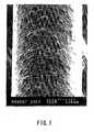
- FIG. 1is a SEM photograph (220x) external view of the fluororesin coated wire obtained in Working Example 1 of the present invention.
- FIG. 2is a schematic cross-sectional view of the same.
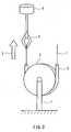
- FIG. 3is an explanatory diagram showing the method for measuring the frictional resistance in the working examples of the present invention.
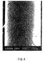
- FIG. 4is a SEM photograph (220x) external view of the fluororesin coated wire obtained in Comparative Example 1 of the present invention.
- FIG. 5is a SEM photograph (220x) external view of the fluororesin coated wire obtained in Comparative Example 2 of the present invention.
- FIG. 6is a SEM photograph (220x) external view of the fluororesin coated wire obtained in Working Example 3 of the present invention.
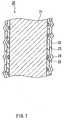
- FIG. 7is a schematic cross-sectional view of the same.
- FIG. 8is an explanatory diagram showing the method for measuring the height of the projections in the working examples of the present invention.
- the particulate matterin either or both the primer layer and the fluororesin coating layer.
- the fluororesin coating layer of the outermost layercovers the particulate matter. Particulate matter having a predetermined average particle diameter is used, and of these, comparatively large particles and agglomerated particles are formed in surface protrusion-shaped projections.
- the fluororesin coating layer and the protruding projection-like fluororesin portionsare baked as a single unit.
- the projection-like fluororesin particlesare formed in smooth projections, and this contributes to lowering the frictional resistance.
- an objectthat comes into contact with them makes point contact, lowering the frictional resistance.
- thisis useful for the medical guide wire for catheters, for example.
- the fluororesin coating layerincludes particulate matter, then it is preferable that the particulate matter is fluororesin.
- the two being compatibleallows them to be baked into a more robust single unit.
- the fluororesin coating layer and the fluororesin projectionsinclude at least one selected from polytetrafluoroethylene (PTFE), tetrafluoroethylene-perfluoroalkylvinyl ether copolymer (PFA), polychlorotrifluoroethylene (PCTFE), polyvinylidene fluoride (PVDF), polyvinyl fluoride (PVF), tetrafluoroethylene-hexafluoropropylene copolymer (FEP), and tetrafluoroethylene-ethylene copolymer (PETFE).
- PTFEpolytetrafluoroethylene
- PFAtetrafluoroethylene-perfluoroalkylvinyl ether copolymer
- PCTFEpolychlorotrifluoroethylene
- PVDFpolyvinylidene fluoride
- PVDFpolyvinyl fluoride
- FEPtetrafluoroethylene-hexafluoropropylene copolymer
- At least one selected from polytetrafluoroethylene (PTFE) and tetrafluoroethylene-perfluoroalkylvinyl ether copolymer (PFA)is preferable. This is because of their relatively high melting point and the fact that they are safe for the human body.
- the thickness of the fluororesin coating layeris at least 1 ⁇ m and not more than 50 ⁇ m. This is because this thickness does not effect the medical operation of the wire. It is also preferable that the average height of the projections is at least 0.1 ⁇ m and not more than 20 ⁇ m. This range is ideal for lowering friction. It is also preferable that the fluororesin coating layer surface has a mixture of flat portions and numerous projections. This shape is ideal for improving the friction characteristics. It is further preferable that the density of the protrusion-shaped fluororesin portions is at least an average of 1 per 0.01 mm 2 in order to lower friction.
- a fluororesinis coated onto a wire surface and baked to achieve a fluororesin coating layer by melting to form flat portions and also baking to melt the fluororesin particles for projections in a single unit with the fluororesin coating layer and form projection portions that after baking take on a smooth particle shape, thereby contributing to their roundness.
- non-baked fluororesin particlesare dispersed in liquid to form the fluororesin dispersion, and also that particles that have been baked are mixed in with the fluororesin particles for projections.
- fluororesin having different melting pointsit is also preferable to mix fluororesin having different melting points, and by mixing fluororesin particles having a higher melting point than the fluororesin dispersion into the fluororesin dispersion, which has a lower melting point, it is possible to form a fluororesin coating layer with excellent roundedness in which deformation of the fluororesin particles due to melting is suppressed.
- PTFEmelting point 327°C
- FEPmelting point 255 to 265°C
- PFAmelting point 305°C
- a method for manufacturing a medical guide wire of the present inventionis a method for manufacturing a guide wire, in which a fluororesin layer is formed on a surface of a metal wire, that includes mixing fluororesin particles for projections into a fluororesin dispersion to prepare a coating solution, applying the solution to the surface of the metal wire, and then baking by heating to at least the melting point of the fluororesin dispersion, thereby forming a fluororesin coating and projection-like fluororesin portions protruding from the fluororesin coating as a single unit on the surface of the metal wire, forming rounded projections.
- the method for applying the fluororesin dispersion or the primer solution to the guide wire surfacecan be any one of brushing, spraying, or the like, but in order to achieve a uniform application, a dipping method is preferable.
- the temperature at which the fluororesin is bakedis between 300 and 450°C, and thus after baking the fluororesin coated wire, the fluororesin is cooled quickly from a molten state, thereby annealing the metal wire and preventing the loss of rigidity as well as obtaining a hard coating layer due to the fluororesin layer cooling quickly.
- cooling quicklymeans cooling of the fluororesin from a molten state at a rate of about 50 to 100°C per second.
- the preferable conditionscan be determined based on the wire diameter and material of the metal wire and the thickness and baking temperature of the fluororesin.
- the fluororesin solid content concentration in the fluororesin dispersion for coatingis 20 to 60 wt%. Within this range, the dispersion is stable.
- [A/(A+B)] ⁇ 100is 1 to 60 wt%. This is because it gives favorable low friction properties. It is preferable that the average particle diameter of the fluororesin microparticles for coating within the fluororesin dispersion is approximately 0.20 to 0.30 ⁇ m when measured by a light dispersion method. It is also preferable that the average particle diameter of the fluororesin particles for projections is at least 0.5 and not more than 30 ⁇ m. This range is ideal for lowering friction.
- the diameter of the fluororesin particles for projectionsis larger than the thickness of the fluororesin coating, then because they are baked into a single unit with the fluororesin for coating, most are deformed due to melting and become smooth projections. If the diameter of the fluororesin particles for projections is smaller than the thickness of the fluororesin coating, then the amount of fluororesin particles for projections that is added can be increased to stack the particles on one another and thereby cause them to protrude from the coating.
- the fluororesin coating layerwhich is the outermost layer, covers the particulate matter, allowing the particulate matter to form protrusion-shaped surface projections.
- the primer layeris a layer for increasing the intimacy of contact between the metal surface of the guide wire and the outermost fluororesin layer.
- the particulate matteris fluororesin or a heat-resistant substance having a higher melting point than the fluororesin coating layer. This is because projections of particle are formed conspicuously after the fluororesin is baked.
- the particulate mattercan be at least one type of particle selected from fluororesin, glass, metal, plastic, inorganic powder, and ceramic.
- the average particle diameter of the particulate matteris at least the film thickness of the primer layer, and preferably the average particle diameter is in the range of 0.5 to 30 ⁇ m. It is also preferable that the thickness of the fluororesin coating layer is at least 1 ⁇ m and not more than 50 ⁇ m. It is also preferable that the average height of the projections is at least 0.1 ⁇ m and not more than 20 ⁇ m. It is also preferable that the amount of particulate matter that is present is 1 to 50 wt% with respect to the solid content mass of the primer solution.
- a metal wire that has a uniform thickness or whose tip is taperedcan be employed favorably as the metal wire in the present invention.
- the wire materialis preferably a superelastic alloy, and for example is Ti-Ni (Ni: 49-51 atomic%, including Ti-Ni to which a third element has been added), Cu-Al-Zn (Al: 3-8 atomic%, Zn: 15-28 atomic%), Fe-Mn-Si (Mn: 30 atomic%, Si: 5 atomic%), Cu-Al-Ni (Ni: 3-5 atomic%, Al: 28-29 atomic%), Ni-Al (Al: 36-38 atomic%), Mn-Cu (Cu: 5-35 atomic%), or Au-Cd (Cd: 46-50 atomic%).
- alloysare known as superelastic alloys or shape memory alloys.
- a Ti-Ni alloyis preferable. Its thickness preferably is selected based on the inner diameter of the catheter with which it is to be used in combination. More specifically, wires having a diameter of approximately 0.3 mm to 1 mm are frequently used.
- a polyurethane resin tube (inner diameter 2.5 mm, outer diameter 4.0 mm, length 200 mm) 2is fixedly adhered over half its circumference to a metal jig 3 having a diameter of 90 mm, and the jig 3 is attached to a fastened chuck 7 of a tensile tester.
- a fluororesin coated wire 1is inserted into the polyurethane resin tube and one end of the wire is fastened to a clip 4 of the tensile tester 5, while the other free end is pulled at a velocity of 50 mm per minute in the direction of an arrow 6, and by measuring the load at this time, the frictional resistance between the wire 1 and the polyurethane resin tube was measured.
- the measurementwas performed by measuring the frictional resistance over any 50 mm portion of the guide wire, and recording those values to a chart and calculating an average value from the data.
- a laser light a1is emitted straight down and the reflection light a2 is received by a light-receiving portion that is not shown, and from its focal length the distance (depth) of the section in question is measured.
- Projections 14also are measured in this fashion, emitting a laser light b1 and receiving reflection light b2, and from that focal length obtaining the distance of that position by measurement.
- the unevenness of a sampleis successively obtained by measurement over a fixed area of the sample from that focal length, calculating the height of the projections 14 regarding the a1 emission portions as flat portions. Measurements are calculated as the average value of five measured values per sample.
- a primer solution(“855-300” made by Dupont) having a 35% solid portion concentration) adjusted to a viscosity of 110 cp (23°C) was coated onto a 2 m length, 0.35 mm diameter Ti-Ni (Ni: 49-51 atomic%) superelastic alloy wire to a dried thickness of approximately 1 ⁇ m and then dried naturally at room temperature for 10 minutes. It was then heated at 150°C for 30 minutes.
- a fluororesin dispersion for coating(“855-510” made by Dupont) was used as the fluororesin of the outermost layer.
- the fluororesin solid concentrationwas 50 wt%.
- PTFE particles for forming projections(“L150J” made by Asahi Glass) (average particle diameter approximately 9 ⁇ m) were added to this dispersion to 20 wt% with respect to the fluororesin mass of the dispersion and then mixed, and this was taken as the coating liquid.
- the coating liquidwas coated over the wire, which had been coated by the primer solution, dried naturally at room temperature (25°C) for 1 minute, heated at 200°C for 10 minutes, then baked at 450°C for 1 minute and cooled to room temperature.
- the thickness of flat portions of the fluororesin coating layerwas approximately 5 ⁇ m, and the average height of projections was approximately 3.5 ⁇ m.
- FIG. 1shows the external appearance of the fluororesin coated wire obtained in this manner.
- FIG. 1is a scanning electron microscope (SEM) photograph taken at 220x magnification. It is clear from FIG. 1 that a fluororesin coating layer and projections at a ratio of at least an average of 1 per 0.01 mm 2 are formed in the fluororesin coating layer surface, that the fluororesin particles and the fluororesin are baked into a single unit, and that the projection-like fluororesin particles are formed in smooth protrusions.
- SEMscanning electron microscope
- FIG. 2is a schematic cross-sectional view of FIG. 1.
- the fluororesin coated wire 1is made of a primer layer 12, a fluororesin coating layer 13, and projections 14 due to the fluororesin particles, baked into a single unit on the surface of a superelastic alloy wire 11.
- the frictional resistance of the fluororesin coated wire thus obtainedwas measured.
- the resultwas an average frictional resistance value for the wire of Working Example 1 of 2.0 g.
- the resultwas dried naturally at room temperature for 1 minute, heated at 200°C for 10 minutes, then baked at 380°C for 1 minute and cooled to room temperature.
- the thickness of the flat portions of the fluororesin coatingwas approximately 5 ⁇ m, and the average height of the projections was approximately 4 ⁇ m.
- the average frictional resistance value of the wire of Working Example 2was 1.8 g.
- FIG. 4shows the external appearance of the fluororesin coated wire.
- FIG. 4is a scanning electron microscope (SEM) photograph taken at 220x magnification. It is clear from FIG. 4 that a fluororesin coating layer having a uniform thickness was formed.
- the frictional resistance value of this fluororesin coated wirewas measured in the same manner as in Working Example 1, and the average frictional resistance value of the wire was found to be 4.5 g.
- PTFE particles having an average particle diameter of 9 ⁇ mwere applied as a fine powder over the wire surface and the fluororesin was baked for 1 minute at a temperature of 450°C.
- FIG. 5shows the external appearance of the fluororesin coated wire.
- FIG. 5is a scanning electron microscope (SEM) photograph taken at 220x magnification. It is clear from FIG. 5 that the fluororesin coating layer has an uneven shape.
- a 2 m length, 0.35 mm diameter Ti-Ni (Ni: 49-51 atomic%) superelastic alloy wirewas prepared.
- 10 wt% aluminum borate "PF03"(made by Shikoku Chemicals Corporation) having a 3 ⁇ m average particle diameter was mixed in and dispersed to "855-300" (made by Dupont) having a 35% solid concentration to serve as a primer solution, and its viscosity was adjusted to 110 cp (23°C).
- the primerwas then coated by an immersion method until a dried thickness of approximately 1.0 ⁇ m, dried naturally at room temperature for 10 minutes, and then heated at 150°C for 30 minutes.
- the numerous aluminum borate projections precipitated on the wire surfacewere applied along with the primer coating.
- a fluororesin dispersion for coating(“AD-1” made by Asahi Glass), where the average diameter of the fluororesin microparticles made of PTFE was measured by light dispersion to be approximately 0.20 ⁇ m, was used for the outermost fluororesin layer.
- the fluororesin solid content concentrationwas 60 wt%, and using (Triton) polyoxyethylene (10) octylphenyl ethyl was adjusted to a viscosity of 150 CP, and this dispersion was taken as the coating liquid of the outermost fluororesin layer.
- This coating liquidwas coated by dripping onto the surface of the wire that had been coated with the primer solution, dried naturally at room temperature for 1 minute, heated at 200°C for 10 minutes, then baked at 400°C for 1 minute and cooled to room temperature.
- the thickness of the flat portions of the fluororesin coating layerwas approximately 6 ⁇ m, and the average height of the projections was approximately 2.0 ⁇ m.
- FIG. 6shows the external appearance of the fluororesin coated wire obtained in this manner.
- FIG. 6is a scanning electron microscope (SEM) photograph taken at 220x magnification. It is clear from FIG. 6 that a guide wire having a coating layer in which the projection-like shapes of the aluminum borate particles mixed into the primer solution were formed as rounded projections coated by the fluororesin on the fluororesin coating layer surface was obtained.
- FIG. 7is a schematic cross-sectional view of the guide wire of this working example.
- a fluororesin coated wire 20is made of a primer layer 22, to which aluminum borate particles 25 have been mixed, and a fluororesin coating layer 23 layered onto the surface of a superelastic alloy wire 21, and the projections 24 in which the aluminum borate particles 25 are coated by the fluororesin layer are coated such that they form smooth projection shapes.
- the average frictional resistance value of the fluororesin coated wire thus obtainedwas 1.5 g.
- PTFE particles("L150J” made by Asahi Glass) (9 ⁇ m average particle diameter) were added in place of the aluminum borate to 20 wt% with respect to the solid concentration of the primer solution and this was mixed, and then this primer solution was coated by immersion to a thickness of 2 ⁇ m onto a 2 m length, 0.35 mm diameter superelastic alloy wire.
- the primer solutionwas then dried naturally at room temperature for 10 minutes and heated at 150°C for 30 minutes and dried. Regarding the dried primer coated surface, the numerous fluororesin projections precipitated on the wire surface were applied along with the primer coating.
- the wire of the present inventionin which a fluororesin coating layer and fluororesin particles for forming projections are baked as a single unit and the projection-like fluororesin particles form smooth protrusions, had the lowest frictional resistance value.
- the fluororesin coating layer and the projections made of particulate matter protruding from the fluororesin coating layer surfaceare baked into a single unit and the protrusions are formed rounded, and thus the frictional resistance between the catheter and the guide wire can be reduced, making the action of inserting the catheter into the body easy. Also, it is not necessary to process, for example deform, the core material itself, and thus characteristics of the core material such as its strength and modulus of elasticity can be utilized as they are.
Landscapes
- Health & Medical Sciences (AREA)
- Life Sciences & Earth Sciences (AREA)
- Veterinary Medicine (AREA)
- Heart & Thoracic Surgery (AREA)
- Public Health (AREA)
- General Health & Medical Sciences (AREA)
- Animal Behavior & Ethology (AREA)
- Vascular Medicine (AREA)
- Epidemiology (AREA)
- Surgery (AREA)
- Biophysics (AREA)
- Pulmonology (AREA)
- Engineering & Computer Science (AREA)
- Anesthesiology (AREA)
- Biomedical Technology (AREA)
- Hematology (AREA)
- Chemical & Material Sciences (AREA)
- Inorganic Chemistry (AREA)
- Media Introduction/Drainage Providing Device (AREA)
- Materials For Medical Uses (AREA)
Abstract
Description
- 1,20
- fluororesin coated wire
- 2
- tube made of resin
- 3
- metal jig
- 4
- clip
- 5
- tensile tester
- 7
- fastened chuck
- 11,21
- superelastic alloy wire
- 12,22
- primer layer
- 13,23
- fluororesin coating layer
- 14,24
- projections
- 25
- aluminum borate particles
Emission Laser: semiconductor laser, wavelength 685 nm
Output: 0.45 mW
Magnification Ratio: 100x
Measurement Depth: 5 µm
Movement Pitch: 0.05 µm
Laser Scan: 9 Hz
Laser Emission Angle: Vertical (emission straight downward from above,and reflection light is received by a light-receiving portion)
Claims (18)
- A medical guide wire in which at least a fluororesin coating layeris formed on a surface of a metal wire,
wherein particulate matter is present in the fluororesin coatinglayer; and
wherein the fluororesin coating layer covers the particulatematter and at least some of the particulate matter is formed in surfaceprotrusion-shaped projections. - The medical guide wire according to claim 1,
wherein a primer layer is further formed within the fluororesincoating layer;
wherein particulate matter is present in at least one layer selectedfrom the primer layer and the fluororesin coating layer; and
wherein the fluororesin coating layer of the outermost layer coversthe particulate matter and at least some of the particulate matter isformed in surface protrusion-shaped projections. - The medical guide wire according to claim 1 or 2,
wherein the fluororesin coating layer includes particulate matter,the particulate matter is fluororesin, and the fluororesin coating and theparticulate matter are baked as a single unit. - The medical guide wire according to any one of claims 1 to 3,
wherein the fluororesin coating layer and the particulate matterinclude at least one selected from the group consisting ofpolytetrafluoroethylene (PTFE), tetrafluoroethylene-perfluoroalkylvinylether copolymer (PFA), polychlorotrifluoroethylene (PCTFE),polyvinylidene fluoride (PVDF), polyvinyl fluoride (PVF),tetrafluoroethylene-hexafluoropropylene copolymer (FEP), andtetrafluoroethylene-ethylene copolymer (PETFE). - The medical guide wire according to any one of claims 1 to 4,
wherein the thickness of the fluororesin coating layer is at least 1µm and not more than 50 µm. - The medical guide wire according to claim 1,
wherein the average height of the projections is at least 0.1 µmand not more than 20 µm. - The medical guide wire according to claim 1,
wherein the fluororesin coating layer surface has a mixture of flatportions and numerous protrusion-shaped projections. - The medical guide wire according to any one of claims 1, 6, or 7,
wherein the density of the protrusion-shaped projections is atleast an average of 1 per 0.01 mm2. - The medical guide wire according to claim 2,
wherein the particulate matter is present in the primer layer, andthe particulate matter is fluororesin or a heat-resistant substance havinga higher melting point than the fluororesin coating layer. - The medical guide wire according to claim 9,
wherein the particulate matter is at least one selected from thegroup consisting of glass particles, metal particles, plastic particles,inorganic particles, and ceramic particles. - The medical guide wire according to claim 9,
wherein an average particle diameter of the particulate matter isat least the film thickness of the primer layer, and the average particlediameter is in a range of 0.5 to 30 µm. - A method for manufacturing a medical guide wire in which at leasta fluororesin coating layer is formed on a surface of a metal wire,comprising:wherein the fluororesin coating layer covers the particulatematter and at least some of the particulate matter is formed in surfaceprotrusion-shaped projections.mixing particulate matter for projections into a fluororesindispersion to prepare a coating solution; andapplying the solution to the surface of the metal wire and dryingthe solution, and then baking by heating to at least the melting point ofthe fluororesin in the fluororesin dispersion; therebycausing particulate matter to be present in the fluororesin coatinglayer;
- A method for manufacturing a medical guide wire in which aprimer layer and a fluororesin coating layer are formed in that order on asurface of a metal wire, comprising:mixing particulate matter into at least one solution selected froma primer solution and a fluororesin dispersion solution;applying the primer solution and the fluororesin dispersionsolution to the surface of the metal wire in that order and drying them;andthen, in a final step, baking by heating to at least the meltingpoint of the fluororesin in the fluororesin dispersion such that thefluororesin coating layer of the outermost layer covers the particulatematter and at least some of the particulate matter is formed in surfaceprotrusion-shaped projections.
- The method for manufacturing a medical guide wire according toclaim 12 or 13,
wherein a fluororesin solid content concentration in thefluororesin dispersion solution for coating is 20 to 60 wt%. - The method for manufacturing a medical guide wire according toany one of claims 12 to 14,
wherein when A is an amount of the particulate matter that isadded and B is the solid content of the fluororesin dispersion, then[A/(A+B)]×100 is 1 to 60 wt%. - The method for manufacturing a medical guide wire according toclaim 12 or 13,
wherein an average particle diameter of the particulate matter is0.5 to 30 µm. - The method for manufacturing a medical guide wire according toclaim 13,
wherein particulate matter is mixed into the primer resin solution to prepare a coating solution. - The method for manufacturing a medical guide wire according toclaim 17,
wherein the amount ofparticulate matter that is present is 1 to 50wt% with respect to the solid content mass of the primer resin solution.
Applications Claiming Priority (3)
| Application Number | Priority Date | Filing Date | Title |
|---|---|---|---|
| JP2002276139 | 2002-09-20 | ||
| JP2002276139 | 2002-09-20 | ||
| PCT/JP2003/011807WO2004026385A1 (en) | 2002-09-20 | 2003-09-17 | Medical guide wire and process for production thereof |
Publications (3)
| Publication Number | Publication Date |
|---|---|
| EP1541188A1true EP1541188A1 (en) | 2005-06-15 |
| EP1541188A4 EP1541188A4 (en) | 2010-11-03 |
| EP1541188B1 EP1541188B1 (en) | 2011-07-06 |
Family
ID=32025059
Family Applications (1)
| Application Number | Title | Priority Date | Filing Date |
|---|---|---|---|
| EP03797620AExpired - LifetimeEP1541188B1 (en) | 2002-09-20 | 2003-09-17 | Medical guide wire and process for production thereof |
Country Status (7)
| Country | Link |
|---|---|
| US (2) | US8162855B2 (en) |
| EP (1) | EP1541188B1 (en) |
| KR (1) | KR101062613B1 (en) |
| CN (1) | CN100493646C (en) |
| AU (1) | AU2003266521A1 (en) |
| CA (1) | CA2499204C (en) |
| WO (1) | WO2004026385A1 (en) |
Cited By (12)
| Publication number | Priority date | Publication date | Assignee | Title |
|---|---|---|---|---|
| WO2007035305A1 (en)* | 2005-09-15 | 2007-03-29 | Wilson-Cook Medical Inc. | Multiple stage wire guide |
| EP2205290A2 (en)* | 2007-10-31 | 2010-07-14 | Senorx, Inc. | Soft body catheter with low friction lumen |
| US8251884B2 (en) | 2005-11-18 | 2012-08-28 | Senorx, Inc. | Methods for asymmetrical irradiation of a body cavity |
| US8277370B2 (en) | 2007-03-12 | 2012-10-02 | Senorx, Inc. | Radiation catheter with multilayered balloon |
| US8292794B2 (en) | 2002-11-06 | 2012-10-23 | Senorx, Inc. | Method for maintaining access to a biopsy site |
| US8360950B2 (en) | 2008-01-24 | 2013-01-29 | Senorx, Inc. | Multilumen brachytherapy balloon catheter |
| US8398535B2 (en) | 2002-11-06 | 2013-03-19 | Senorx, Inc. | Catheter assembly for delivering a radiation source into a body cavity |
| US9623260B2 (en) | 2004-11-05 | 2017-04-18 | Theragenics Corporation | Expandable brachytherapy device |
| US10022557B2 (en) | 2010-09-30 | 2018-07-17 | Hologic, Inc. | Using a guided member to facilitate brachytherapy device swap |
| IT201700073563A1 (en)* | 2017-06-30 | 2018-12-30 | Getters Spa | SETS ACTUATORS INCLUDING WIRES ALLOY WITH SHAPE MEMORY AND COATINGS WITH PHASE-MADE MATERIALS PARTICLES |
| US10207126B2 (en) | 2009-05-11 | 2019-02-19 | Cytyc Corporation | Lumen visualization and identification system for multi-lumen balloon catheter |
| US10342992B2 (en) | 2011-01-06 | 2019-07-09 | Hologic, Inc. | Orienting a brachytherapy applicator |
Families Citing this family (24)
| Publication number | Priority date | Publication date | Assignee | Title |
|---|---|---|---|---|
| US7687144B2 (en)* | 2003-02-20 | 2010-03-30 | Wilson-Cook Medical, Inc. | Medical device with adherent coating, and method for preparing same |
| JP2007202846A (en)* | 2006-02-02 | 2007-08-16 | Ist Corp | Sliding member and manufacturing method thereof |
| JP2008000287A (en)* | 2006-06-21 | 2008-01-10 | Terumo Corp | Sliding composition for coating medical appliance and medical appliance with sliding coat |
| JP2008086575A (en)* | 2006-10-02 | 2008-04-17 | Ist Corp | Method for producing colored medical device |
| US20080119762A1 (en)* | 2006-11-16 | 2008-05-22 | Tateishi Tadasu | Guide wire |
| EP2103323B1 (en)* | 2007-03-14 | 2012-04-25 | Terumo Kabushiki Kaisha | Guide wire |
| WO2009004876A1 (en)* | 2007-06-29 | 2009-01-08 | Piolax Medical Devices, Inc. | Guide wire |
| US20110260945A1 (en)* | 2007-08-03 | 2011-10-27 | Fumio Karasawa | Coating Composition and Article Using the Same |
| US7714217B2 (en)* | 2007-12-21 | 2010-05-11 | Innovatech, Llc | Marked precoated strings and method of manufacturing same |
| EP2226091B1 (en) | 2007-12-26 | 2019-09-18 | Terumo Kabushiki Kaisha | Medical long element, method for manufacturing the same, and apparatus for manufacturing the same |
| US9579524B2 (en) | 2009-02-11 | 2017-02-28 | Hologic, Inc. | Flexible multi-lumen brachytherapy device |
| US9248311B2 (en) | 2009-02-11 | 2016-02-02 | Hologic, Inc. | System and method for modifying a flexibility of a brachythereapy catheter |
| KR101714377B1 (en) | 2015-04-09 | 2017-03-10 | 한국과학기술연구원 | Multi-functional Sensor assembly |
| KR101692618B1 (en) | 2015-04-20 | 2017-01-04 | 한밭대학교 산학협력단 | Method for the medical metal wires with teflon |
| DE102015109499A1 (en) | 2015-06-15 | 2016-12-15 | Plümat Plate & Lübeck GmbH & Co. | Apparatus and method for producing plastic bags |
| US10258765B2 (en)* | 2016-08-02 | 2019-04-16 | Hitachi Metals, Ltd. | Cable and medical hollow tube |
| JP6171239B1 (en)* | 2016-08-02 | 2017-08-02 | 株式会社エフエムディ | Medical guide wire and method for manufacturing medical guide wire |
| CN109803563B (en) | 2016-10-12 | 2022-05-10 | 科慕埃弗西有限公司 | Low bake temperature fluoropolymer coatings |
| US11286615B2 (en) | 2018-05-17 | 2022-03-29 | Hitachi Metals, Ltd. | Cable and medical hollow tube |
| US10744231B1 (en)* | 2019-08-07 | 2020-08-18 | Zeus Industrial Products, Inc. | Catheter comprising PTFE liner |
| US11992643B2 (en)* | 2019-12-20 | 2024-05-28 | Neuravi Limited | Neurovascular insertion tool |
| EP4223349A4 (en)* | 2020-10-02 | 2024-07-17 | Asahi Intecc Co., Ltd. | LONG MEDICAL INSTRUMENT |
| US12178974B2 (en) | 2021-01-21 | 2024-12-31 | Abbott Cardiovascular Systems Inc. | Guidewire and method of use |
| CN115887786B (en)* | 2022-11-16 | 2024-03-12 | 中国中医科学院望京医院(中国中医科学院骨伤科研究所) | Polyvinylidene fluoride coated nano composite pipe and preparation method thereof |
Family Cites Families (25)
| Publication number | Priority date | Publication date | Assignee | Title |
|---|---|---|---|---|
| CA1153264A (en)* | 1979-02-08 | 1983-09-06 | Hidenaga Yoshimura | Medical vascular guide wire and self-guiding type catheter |
| JPS5663365A (en) | 1979-10-26 | 1981-05-29 | Toray Monofilament Co | Antiithrombus medical flow guide wire |
| JPS58215370A (en)* | 1982-06-10 | 1983-12-14 | Seiko Epson Corp | Ink type wire dot printer |
| JP2540211B2 (en) | 1989-07-10 | 1996-10-02 | テルモ株式会社 | Guide wire |
| US5404887A (en)* | 1993-11-04 | 1995-04-11 | Scimed Life Systems, Inc. | Guide wire having an unsmooth exterior surface |
| US5626907A (en)* | 1994-02-26 | 1997-05-06 | E. I. Dupont De Nemours And Company | Process for coating metal surfaces with a fluororesin using a primer |
| EP0828524A2 (en)* | 1995-05-05 | 1998-03-18 | Advanced Cardiovascular Systems, Inc. | Intraluminal device with lubricious surface |
| JP3306271B2 (en)* | 1995-08-23 | 2002-07-24 | 三洋電機株式会社 | Encoding method, encoding circuit, and decoding circuit |
| JP3074142B2 (en)* | 1996-04-22 | 2000-08-07 | 株式会社セイシン企業 | Composite powder for forming surface coating film of fluorine resin and method for producing the same |
| WO1998007523A1 (en)* | 1996-08-23 | 1998-02-26 | Pursley Matt D | Apparatus and method for nonextrusion manufacturing of catheters |
| AU6118098A (en)* | 1997-02-28 | 1998-09-18 | Yuichi Mori | Coating composition, coated object, and coating method |
| US20020172829A1 (en)* | 1997-02-28 | 2002-11-21 | Yuichi Mori | Coating composition, coating product and coating method |
| US5924998A (en)* | 1997-03-06 | 1999-07-20 | Scimed Life System, Inc. | Guide wire with hydrophilically coated tip |
| JPH1119217A (en)* | 1997-07-04 | 1999-01-26 | Olympus Optical Co Ltd | Medical guide wire |
| JP3180073B2 (en) | 1997-12-24 | 2001-06-25 | 住友ベークライト株式会社 | Medical guidewire |
| US6086970A (en)* | 1998-04-28 | 2000-07-11 | Scimed Life Systems, Inc. | Lubricious surface extruded tubular members for medical devices |
| US6306105B1 (en)* | 1998-05-14 | 2001-10-23 | Scimed Life Systems, Inc. | High performance coil wire |
| CN2342833Y (en)* | 1998-07-03 | 1999-10-13 | 蒲忠杰 | Lead wires for coronary angioplasty |
| US6291054B1 (en)* | 1999-02-19 | 2001-09-18 | E. I. Du Pont De Nemours And Company | Abrasion resistant coatings |
| JP3556514B2 (en)* | 1999-03-26 | 2004-08-18 | オリンパス株式会社 | Medical equipment |
| JP2001238962A (en) | 2000-02-29 | 2001-09-04 | Japan Lifeline Co Ltd | Medical insertion wire |
| CN2424784Y (en)* | 2000-05-19 | 2001-03-28 | 江阴法尔胜吉特有限公司 | Superelastic medical guide wire of nickel-titanium alloy |
| EP1318845B1 (en)* | 2000-09-11 | 2006-12-20 | Union Carbide Chemicals & Plastics Technology Corporation | Hydrophilic, lubricious medical devices having contrast for magnetic resonance imaging |
| JP4236802B2 (en)* | 2000-09-22 | 2009-03-11 | 日本ライフライン株式会社 | Lubricating medical device and manufacturing method thereof |
| US6669652B2 (en)* | 2000-12-21 | 2003-12-30 | Advanced Cardiovascular Systems, Inc. | Guidewire with tapered distal coil |
- 2003
- 2003-09-17EPEP03797620Apatent/EP1541188B1/ennot_activeExpired - Lifetime
- 2003-09-17USUS10/527,417patent/US8162855B2/enactiveActive
- 2003-09-17CNCNB038223643Apatent/CN100493646C/ennot_activeExpired - Lifetime
- 2003-09-17AUAU2003266521Apatent/AU2003266521A1/ennot_activeAbandoned
- 2003-09-17WOPCT/JP2003/011807patent/WO2004026385A1/enactiveApplication Filing
- 2003-09-17CACA2499204Apatent/CA2499204C/ennot_activeExpired - Lifetime
- 2003-09-17KRKR1020057004855Apatent/KR101062613B1/ennot_activeExpired - Lifetime
- 2011
- 2011-03-29USUS13/074,786patent/US8192373B2/ennot_activeExpired - Fee Related
Cited By (23)
| Publication number | Priority date | Publication date | Assignee | Title |
|---|---|---|---|---|
| US8292794B2 (en) | 2002-11-06 | 2012-10-23 | Senorx, Inc. | Method for maintaining access to a biopsy site |
| US8517906B2 (en) | 2002-11-06 | 2013-08-27 | Hologic, Inc. | Brachytherapy device |
| US8398535B2 (en) | 2002-11-06 | 2013-03-19 | Senorx, Inc. | Catheter assembly for delivering a radiation source into a body cavity |
| US9808650B2 (en) | 2004-11-05 | 2017-11-07 | Theragenics Corporation | Expandable brachytherapy device |
| US9623260B2 (en) | 2004-11-05 | 2017-04-18 | Theragenics Corporation | Expandable brachytherapy device |
| WO2007035305A1 (en)* | 2005-09-15 | 2007-03-29 | Wilson-Cook Medical Inc. | Multiple stage wire guide |
| US10413750B2 (en) | 2005-11-18 | 2019-09-17 | Hologic, Inc. | Brachytherapy device for facilitating asymmetrical irradiation of a body cavity |
| US8251884B2 (en) | 2005-11-18 | 2012-08-28 | Senorx, Inc. | Methods for asymmetrical irradiation of a body cavity |
| US8636637B2 (en) | 2005-11-18 | 2014-01-28 | Hologic, Inc | Methods for asymmetrical irradiation of a body cavity |
| US9180312B2 (en) | 2005-11-18 | 2015-11-10 | Hologic, Inc. | Brachytherapy device for asymmetrical irradiation of a body cavity |
| US9415239B2 (en) | 2005-11-18 | 2016-08-16 | Hologic, Inc. | Brachytherapy device for facilitating asymmetrical irradiation of a body cavity |
| US8277370B2 (en) | 2007-03-12 | 2012-10-02 | Senorx, Inc. | Radiation catheter with multilayered balloon |
| US8287442B2 (en) | 2007-03-12 | 2012-10-16 | Senorx, Inc. | Radiation catheter with multilayered balloon |
| US8758214B2 (en) | 2007-03-12 | 2014-06-24 | Hologic, Inc. | Radiation catheter with multilayered balloon |
| EP2205290A2 (en)* | 2007-10-31 | 2010-07-14 | Senorx, Inc. | Soft body catheter with low friction lumen |
| US8740763B2 (en) | 2008-01-24 | 2014-06-03 | Hologic Inc. | Multilumen brachytherapy balloon catheter |
| US8360950B2 (en) | 2008-01-24 | 2013-01-29 | Senorx, Inc. | Multilumen brachytherapy balloon catheter |
| US10207126B2 (en) | 2009-05-11 | 2019-02-19 | Cytyc Corporation | Lumen visualization and identification system for multi-lumen balloon catheter |
| US10022557B2 (en) | 2010-09-30 | 2018-07-17 | Hologic, Inc. | Using a guided member to facilitate brachytherapy device swap |
| US10342992B2 (en) | 2011-01-06 | 2019-07-09 | Hologic, Inc. | Orienting a brachytherapy applicator |
| IT201700073563A1 (en)* | 2017-06-30 | 2018-12-30 | Getters Spa | SETS ACTUATORS INCLUDING WIRES ALLOY WITH SHAPE MEMORY AND COATINGS WITH PHASE-MADE MATERIALS PARTICLES |
| WO2019003198A1 (en)* | 2017-06-30 | 2019-01-03 | Saes Getters S.P.A. | Actuator assemblies comprising shape memory alloy wires and a coating with phase changing materials particles |
| US11560881B2 (en) | 2017-06-30 | 2023-01-24 | Saes Getters S.P.A. | Actuator assemblies comprising shape memory alloy wires and a coating with phase changing materials particles |
Also Published As
| Publication number | Publication date |
|---|---|
| CN100493646C (en) | 2009-06-03 |
| EP1541188A4 (en) | 2010-11-03 |
| US8162855B2 (en) | 2012-04-24 |
| US8192373B2 (en) | 2012-06-05 |
| CA2499204A1 (en) | 2004-04-01 |
| WO2004026385A1 (en) | 2004-04-01 |
| CA2499204C (en) | 2011-04-19 |
| KR20050032126A (en) | 2005-04-06 |
| AU2003266521A1 (en) | 2004-04-08 |
| KR101062613B1 (en) | 2011-09-05 |
| WO2004026385B1 (en) | 2004-05-13 |
| EP1541188B1 (en) | 2011-07-06 |
| CN1681554A (en) | 2005-10-12 |
| US20060073264A1 (en) | 2006-04-06 |
| US20110177230A1 (en) | 2011-07-21 |
Similar Documents
| Publication | Publication Date | Title |
|---|---|---|
| EP1541188B1 (en) | Medical guide wire and process for production thereof | |
| JP5412013B2 (en) | Medical catheter tube and manufacturing method thereof | |
| JP2540211B2 (en) | Guide wire | |
| EP0395098B1 (en) | Readily operable catheter guide wire using shape memory alloy with pseudo elasticity | |
| JP3876243B2 (en) | Medical guide wire and manufacturing method thereof | |
| JPH11290448A (en) | Medical tubing | |
| JP2000135289A (en) | Medical guide wire and manufacture of the same | |
| US20220142798A1 (en) | Intravascular functional element, system having a functional element, and method | |
| EP3900649A1 (en) | Stent and catheter-stent system | |
| US20070096357A1 (en) | Medical tube and method for manufacturing the same | |
| JP2006068497A (en) | Method for manufacturing medical wire and medical wire | |
| JP2000225196A (en) | Catheter tube and method of manufacturing the same | |
| KR101692618B1 (en) | Method for the medical metal wires with teflon | |
| US20250152920A1 (en) | Metal wire for medical device, medical device, and method for manufacturing metal wire for medical device | |
| JP2013172926A (en) | Medical guide wire | |
| EP4034686A1 (en) | Wires of nickel-titanium alloy and methods of forming the same | |
| JP7518956B1 (en) | Metal wire and guidewire for medical devices | |
| JP2002045428A (en) | Thin PTFE tube for catheter, method for producing the same, and catheter tube | |
| JP2007260382A (en) | Core material for manufacture of catheter tube, manufacturing method thereof, catheter tube, and manufacturing method thereof | |
| JPH048065B2 (en) | ||
| JP3698449B2 (en) | Guide wire and manufacturing method thereof | |
| JP2009082651A (en) | Catheter tube molding core material and production method thereof | |
| WO2024035769A1 (en) | Composite wire with coating | |
| JPH0674148U (en) | Tear tube made of tetrafluoroethylene resin | |
| JP2006115975A (en) | Manufacturing method of medical guide wire |
Legal Events
| Date | Code | Title | Description |
|---|---|---|---|
| PUAI | Public reference made under article 153(3) epc to a published international application that has entered the european phase | Free format text:ORIGINAL CODE: 0009012 | |
| 17P | Request for examination filed | Effective date:20050315 | |
| AK | Designated contracting states | Kind code of ref document:A1 Designated state(s):AT BE BG CH CY CZ DE DK EE ES FI FR GB GR HU IE IT LI LU MC NL PT RO SE SI SK TR | |
| AX | Request for extension of the european patent | Extension state:AL LT LV MK | |
| DAX | Request for extension of the european patent (deleted) | ||
| RBV | Designated contracting states (corrected) | Designated state(s):CH DE FR GB IT LI | |
| A4 | Supplementary search report drawn up and despatched | Effective date:20101006 | |
| RIC1 | Information provided on ipc code assigned before grant | Ipc:A61M 25/09 20060101ALI20100930BHEP Ipc:A61L 31/14 20060101ALI20100930BHEP Ipc:A61L 31/10 20060101AFI20100930BHEP | |
| GRAP | Despatch of communication of intention to grant a patent | Free format text:ORIGINAL CODE: EPIDOSNIGR1 | |
| RIC1 | Information provided on ipc code assigned before grant | Ipc:A61M 25/09 20060101ALI20110127BHEP Ipc:A61L 31/14 20060101ALI20110127BHEP Ipc:A61L 31/10 20060101AFI20110127BHEP | |
| GRAS | Grant fee paid | Free format text:ORIGINAL CODE: EPIDOSNIGR3 | |
| GRAA | (expected) grant | Free format text:ORIGINAL CODE: 0009210 | |
| AK | Designated contracting states | Kind code of ref document:B1 Designated state(s):CH DE FR GB IT LI | |
| REG | Reference to a national code | Ref country code:GB Ref legal event code:FG4D | |
| REG | Reference to a national code | Ref country code:CH Ref legal event code:EP | |
| REG | Reference to a national code | Ref country code:DE Ref legal event code:R096 Ref document number:60337639 Country of ref document:DE Effective date:20110901 | |
| REG | Reference to a national code | Ref country code:CH Ref legal event code:NV Representative=s name:PATENTANWAELTE SCHAAD, BALASS, MENZL & PARTNER AG | |
| REG | Reference to a national code | Ref country code:CH Ref legal event code:PUE Owner name:SEVEN DREAMERS LABORATORIES, INC. Free format text:I.S.T. CORPORATION#13-13, ICHIRIYAMA, 5-CHOME#OTSU-SHI, SHIGA 520-2153 (JP) -TRANSFER TO- SEVEN DREAMERS LABORATORIES, INC.#303 TWIN DOLPHIN DRIVE, SUITE 600#REDWOOD SHORES, CA 94065 (US) | |
| REG | Reference to a national code | Ref country code:DE Ref legal event code:R081 Ref document number:60337639 Country of ref document:DE Owner name:SEVEN DREAMERS LABORATORIES INC., REDWOOD SHOR, US Free format text:FORMER OWNER: I.S.T CORP., OTSU-SHI, SHIGA, JP Effective date:20110714 Ref country code:DE Ref legal event code:R082 Ref document number:60337639 Country of ref document:DE Representative=s name:STIPPL PATENTANWAELTE, DE Effective date:20120216 Ref country code:DE Ref legal event code:R081 Ref document number:60337639 Country of ref document:DE Owner name:SEVEN DREAMERS LABORATORIES INC., REDWOOD SHOR, US Free format text:FORMER OWNER: I.S.T. CORP., OHTSU, SHIGA, JP Effective date:20120216 Ref country code:DE Ref legal event code:R081 Ref document number:60337639 Country of ref document:DE Owner name:SEVEN DREAMERS LABORATORIES, INC., JP Free format text:FORMER OWNER: I.S.T. CORP., OHTSU, SHIGA, JP Effective date:20120216 Ref country code:DE Ref legal event code:R081 Ref document number:60337639 Country of ref document:DE Owner name:SEVEN DREAMERS LABORATORIES, INC., JP Free format text:FORMER OWNER: I.S.T CORP., OTSU-SHI, SHIGA, JP Effective date:20110714 Ref country code:DE Ref legal event code:R081 Ref document number:60337639 Country of ref document:DE Owner name:NANOS MEDICAL (SHANGHAI) LTD., CN Free format text:FORMER OWNER: I.S.T. CORP., OHTSU, SHIGA, JP Effective date:20120216 Ref country code:DE Ref legal event code:R081 Ref document number:60337639 Country of ref document:DE Owner name:NANOS MEDICAL (SHANGHAI) LTD., CN Free format text:FORMER OWNER: I.S.T CORP., OTSU-SHI, SHIGA, JP Effective date:20110714 | |
| PLBE | No opposition filed within time limit | Free format text:ORIGINAL CODE: 0009261 | |
| STAA | Information on the status of an ep patent application or granted ep patent | Free format text:STATUS: NO OPPOSITION FILED WITHIN TIME LIMIT | |
| REG | Reference to a national code | Ref country code:GB Ref legal event code:732E Free format text:REGISTERED BETWEEN 20120419 AND 20120425 | |
| 26N | No opposition filed | Effective date:20120411 | |
| REG | Reference to a national code | Ref country code:DE Ref legal event code:R097 Ref document number:60337639 Country of ref document:DE Effective date:20120411 | |
| REG | Reference to a national code | Ref country code:CH Ref legal event code:PUE Owner name:SEVEN DREAMERS LABORATORIES, INC., JP Free format text:FORMER OWNER: SEVEN DREAMERS LABORATORIES, INC., US Ref country code:CH Ref legal event code:NV Representative=s name:PATENTANWALT MATTHIAS W. SCHAEFER, CH | |
| REG | Reference to a national code | Ref country code:DE Ref legal event code:R082 Ref document number:60337639 Country of ref document:DE Representative=s name:STIPPL PATENTANWAELTE, DE | |
| REG | Reference to a national code | Ref country code:GB Ref legal event code:732E Free format text:REGISTERED BETWEEN 20141127 AND 20141203 | |
| REG | Reference to a national code | Ref country code:FR Ref legal event code:TP Owner name:SEVEN DREAMERS LABORATORIES, INC., JP Effective date:20141203 | |
| REG | Reference to a national code | Ref country code:DE Ref legal event code:R082 Ref document number:60337639 Country of ref document:DE Representative=s name:STIPPL PATENTANWAELTE, DE Effective date:20141210 Ref country code:DE Ref legal event code:R081 Ref document number:60337639 Country of ref document:DE Owner name:SEVEN DREAMERS LABORATORIES, INC., JP Free format text:FORMER OWNER: SEVEN DREAMERS LABORATORIES INC., REDWOOD SHORES, CALIF., US Effective date:20141210 Ref country code:DE Ref legal event code:R081 Ref document number:60337639 Country of ref document:DE Owner name:NANOS MEDICAL (SHANGHAI) LTD., CN Free format text:FORMER OWNER: SEVEN DREAMERS LABORATORIES INC., REDWOOD SHORES, CALIF., US Effective date:20141210 | |
| REG | Reference to a national code | Ref country code:FR Ref legal event code:PLFP Year of fee payment:13 | |
| REG | Reference to a national code | Ref country code:DE Ref legal event code:R082 Ref document number:60337639 Country of ref document:DE Representative=s name:STIPPL PATENTANWAELTE, DE Ref country code:DE Ref legal event code:R081 Ref document number:60337639 Country of ref document:DE Owner name:NANOS MEDICAL (SHANGHAI) LTD., CN Free format text:FORMER OWNER: SEVEN DREAMERS LABORATORIES, INC., TOKIO/TOKYO, JP | |
| REG | Reference to a national code | Ref country code:CH Ref legal event code:PUE Owner name:NANOS MEDICAL (SHANGHAI) LIMITED, CN Free format text:FORMER OWNER: SEVEN DREAMERS LABORATORIES, INC., JP | |
| REG | Reference to a national code | Ref country code:GB Ref legal event code:732E Free format text:REGISTERED BETWEEN 20160818 AND 20160824 | |
| REG | Reference to a national code | Ref country code:FR Ref legal event code:PLFP Year of fee payment:14 | |
| REG | Reference to a national code | Ref country code:FR Ref legal event code:TP Owner name:NANOS MEDICAL (SHANGAI) LIMITED, CN Effective date:20160902 | |
| REG | Reference to a national code | Ref country code:FR Ref legal event code:PLFP Year of fee payment:15 | |
| REG | Reference to a national code | Ref country code:CH Ref legal event code:PCAR Free format text:NEW ADDRESS: SPLUEGENSTRASSE 10, 8002 ZUERICH (CH) | |
| REG | Reference to a national code | Ref country code:FR Ref legal event code:PLFP Year of fee payment:16 | |
| PGFP | Annual fee paid to national office [announced via postgrant information from national office to epo] | Ref country code:GB Payment date:20220920 Year of fee payment:20 Ref country code:DE Payment date:20220920 Year of fee payment:20 | |
| PGFP | Annual fee paid to national office [announced via postgrant information from national office to epo] | Ref country code:FR Payment date:20220922 Year of fee payment:20 | |
| PGFP | Annual fee paid to national office [announced via postgrant information from national office to epo] | Ref country code:IT Payment date:20220926 Year of fee payment:20 | |
| PGFP | Annual fee paid to national office [announced via postgrant information from national office to epo] | Ref country code:CH Payment date:20220928 Year of fee payment:20 | |
| REG | Reference to a national code | Ref country code:DE Ref legal event code:R071 Ref document number:60337639 Country of ref document:DE | |
| REG | Reference to a national code | Ref country code:CH Ref legal event code:PL | |
| REG | Reference to a national code | Ref country code:GB Ref legal event code:PE20 Expiry date:20230916 | |
| PG25 | Lapsed in a contracting state [announced via postgrant information from national office to epo] | Ref country code:GB Free format text:LAPSE BECAUSE OF EXPIRATION OF PROTECTION Effective date:20230916 |