EP1540484B1 - Bus control arrangement and method - Google Patents
Bus control arrangement and methodDownload PDFInfo
- Publication number
- EP1540484B1 EP1540484B1EP02773073AEP02773073AEP1540484B1EP 1540484 B1EP1540484 B1EP 1540484B1EP 02773073 AEP02773073 AEP 02773073AEP 02773073 AEP02773073 AEP 02773073AEP 1540484 B1EP1540484 B1EP 1540484B1
- Authority
- EP
- European Patent Office
- Prior art keywords
- data
- databus
- unit
- transmission
- sequence
- Prior art date
- Legal status (The legal status is an assumption and is not a legal conclusion. Google has not performed a legal analysis and makes no representation as to the accuracy of the status listed.)
- Expired - Lifetime
Links
Images

Classifications
- G—PHYSICS
- G06—COMPUTING OR CALCULATING; COUNTING
- G06F—ELECTRIC DIGITAL DATA PROCESSING
- G06F13/00—Interconnection of, or transfer of information or other signals between, memories, input/output devices or central processing units
- G06F13/38—Information transfer, e.g. on bus
- G06F13/42—Bus transfer protocol, e.g. handshake; Synchronisation
- G06F13/4282—Bus transfer protocol, e.g. handshake; Synchronisation on a serial bus, e.g. I2C bus, SPI bus
- G06F13/4291—Bus transfer protocol, e.g. handshake; Synchronisation on a serial bus, e.g. I2C bus, SPI bus using a clocked protocol
- H—ELECTRICITY
- H04—ELECTRIC COMMUNICATION TECHNIQUE
- H04L—TRANSMISSION OF DIGITAL INFORMATION, e.g. TELEGRAPHIC COMMUNICATION
- H04L12/00—Data switching networks
- H04L12/28—Data switching networks characterised by path configuration, e.g. LAN [Local Area Networks] or WAN [Wide Area Networks]
- H04L12/40—Bus networks
- H04L12/403—Bus networks with centralised control, e.g. polling
- H—ELECTRICITY
- H04—ELECTRIC COMMUNICATION TECHNIQUE
- H04L—TRANSMISSION OF DIGITAL INFORMATION, e.g. TELEGRAPHIC COMMUNICATION
- H04L69/00—Network arrangements, protocols or services independent of the application payload and not provided for in the other groups of this subclass
- H04L69/24—Negotiation of communication capabilities
- H—ELECTRICITY
- H04—ELECTRIC COMMUNICATION TECHNIQUE
- H04L—TRANSMISSION OF DIGITAL INFORMATION, e.g. TELEGRAPHIC COMMUNICATION
- H04L69/00—Network arrangements, protocols or services independent of the application payload and not provided for in the other groups of this subclass
- H04L69/30—Definitions, standards or architectural aspects of layered protocol stacks
- H04L69/32—Architecture of open systems interconnection [OSI] 7-layer type protocol stacks, e.g. the interfaces between the data link level and the physical level
- H04L69/322—Intralayer communication protocols among peer entities or protocol data unit [PDU] definitions
- H04L69/324—Intralayer communication protocols among peer entities or protocol data unit [PDU] definitions in the data link layer [OSI layer 2], e.g. HDLC
- H—ELECTRICITY
- H04—ELECTRIC COMMUNICATION TECHNIQUE
- H04L—TRANSMISSION OF DIGITAL INFORMATION, e.g. TELEGRAPHIC COMMUNICATION
- H04L12/00—Data switching networks
- H04L12/28—Data switching networks characterised by path configuration, e.g. LAN [Local Area Networks] or WAN [Wide Area Networks]
- H04L12/40—Bus networks
- H04L12/4013—Management of data rate on the bus
- Y—GENERAL TAGGING OF NEW TECHNOLOGICAL DEVELOPMENTS; GENERAL TAGGING OF CROSS-SECTIONAL TECHNOLOGIES SPANNING OVER SEVERAL SECTIONS OF THE IPC; TECHNICAL SUBJECTS COVERED BY FORMER USPC CROSS-REFERENCE ART COLLECTIONS [XRACs] AND DIGESTS
- Y10—TECHNICAL SUBJECTS COVERED BY FORMER USPC
- Y10S—TECHNICAL SUBJECTS COVERED BY FORMER USPC CROSS-REFERENCE ART COLLECTIONS [XRACs] AND DIGESTS
- Y10S370/00—Multiplex communications
- Y10S370/912—Packet communications
Definitions
- the present inventionrelates to a method and arrangement for controlling dataflow on a data bus, especially for avoiding reception problems by a receiver unit, said databus connecting at least one receiver unit to one or several transmitter units.
- HDLCHigh-level Data Link Control
- ISDN's D-channeluses a slightly modified version of HDLC
- HDLCuses the term "frame" to indicate an entity of data (or a protocol data unit) transmitted from one station to another.
- Fig. 1is a graphical representation of a HDLC frame with an Information field.
- Flag sequence fieldF.
- Stations attached to the data linkmust continually listen for a flag sequence.
- the flag sequencecan be an octet looking like 01111110. Flags are continuously transmitted on the link between frames to keep the link active.
- Two other bit sequencesare used in HDLC as signals for the stations on the link. According to one exemplary embodiment, these two bit sequences are:
- the time between the transmissions of actual framesis called the interframe time fill.
- the interframe time fillis accomplished by transmitting continuous flags between frames.
- the flagsmay be in 8 bit multiples.
- HDLCis a code-transparent protocol. It does not rely on a specific code for interpretation of line control. This means that a bit at position N in an octet has a specific meaning, regardless of the other bits in the same octet. If an octet has a bit sequence of 01111110, but is not a flag field, HDLC uses a technique called bit-stuffing to differentiate this bit sequence from a flag field. Once the transmitter detects that it is sending 5 consecutive 1's, in inserts a 0 bit to prevent a "phony" flag.
- the receiving stationinspects the incoming frame. If it detects 5 consecutive 1's it looks at the next bit. If it is a 0, it pulls it out. If it is a 1, it looks at the 8 th bit. If the 8 th bit is a 1, it knows that an abort or idle signal has been sent. It then proceeds to inspect the following bits to determine appropriate action.
- HDLCachieves code-transparency in this manner. HDLC is not concerned with any specific bit code inside the data stream. It is only concerned with keeping flags unique.
- the routing function of the busi.e. the bus-master
- the routing function of the busi.e. the bus-master
- its buffersbecome filled.
- the incoming trafficcannot be handled.
- the slavesi.e. the units transmitting data to the master
- Fig. 2illustrates a simple data link comprising a number of Transmitters and a Receiver. The data flow is through an uplink bus. In case of an overflow state, the receiver signals the transmitters to stop sending data.
- JP 10013878a stable communication processing at all times by limiting received calls from an ISDN line network depending on a data transmission quantity of a data input system is attained.
- a main CPU of a control unitmonitors a data transmission quantity of a data highway based on a residual capacity of a dual port RAM, and a main CPU of an ISDN line interface unit monitors a data transmission quantity of the data highway 13 based on a residual capacity of a dual port RAM.
- either or both the main CPU and the main CPUgive an input reject request to a line internal bus interface/HDLC controller of the ISDN line interface unit to allow the controller to send the call reception reject request to an ISDN line network thereby limiting the arrival of succeeding data and preventing overload of reception data input system, resulting in conducting stable communication processing.
- EP 647 082concerns a data link controller (DLC), which employs buffers on both receiving and transmitting sides. These last-in, first-out buffers contain a position indicating that a character is the last one of a packet. In this way, a user need not monitor reception or transmission on a character-by-character basis, but need only concern themselves with packets.
- the receive and transmit FIFO'sgenerate requests for more characters by monitoring the number of characters stored and thereby automatically receive and transmit characters without processor intervention.
- a four-stage mechanismpermits monitoring of multiple contiguous frames (back-to-back frames) received. Control of the DLC is provided by status and control registers, which are accessible to the user via a microprocessor interface.
- Particular registershave bit positions monitoring status conditions in such a manner that the most-probable one of a set of conditions comprises the least-significant bit position, while the least-probable condition occupies the most-significant bit position. This affords simple shift and test technique for monitoring status conditions.
- US 5,878,279relates to an integrated HDLC circuit of the type including at least one HDLC controller and one DMA controller, and means for organizing the access to a first external bus for connection to an external memory, via an internal bus to which are connected different entities, which require to have access to the external memory, the internal bus being connected to the first external bus via a memory controller integrated in the HDLC circuit.
- a signal computing busincludes two bus structures: (a) a synchronous TDM data transport referred to as a data bus and (b) a serial message passing bus referred to as a message bus.
- the following three groups of functionsare performed using the SCbus: (a) data transport over the data bus, (b) message passing over the message bus, and (c) data and message bus control.
- the data busutilizes: 2 clocks, 1 frame pulse, 16 data busses, and 1 clock control (the clock control signal enables access to the bus and automatic switching from one clock master to another when an error is detected) and the message bus is fabricated using a master HDLC protocol with contention resolution.
- EP 238 255relates to an interface arrangement, which interconnects a business communication system with a telephone station set. All signaling from the business communication system is received by the personal computer, interpreted, and appropriate control signals are then forwarded under control of the software resident on the personal computer to activate the digital telephone station set. The signals from the digital telephone station set are intercepted by the personal computer, interpreted, modified and appropriate control messages and signaling are then forwarded by the personal computer to the business communication system.
- This arrangementenables a user to create software on the personal computer to control the operation of the telephone station set associated with the personal computer.
- EP 1 014 626relates to a method, apparatus and network device for controlling the flow of network data arranged in frames and minimizing congestion, such as in the receive port of an HDLC controller.
- the objectis achieved by generating a status error indicator within a receive FIFO memory indicative of a frame overflow within the receive FIFO memory.
- an early congestion interruptis generated to a host processor indicative that a frame overflow has occurred within the receive FIFO memory.
- the incoming frameis discrarded and the services of received frames are enhanced by one of either increasing the number of words of a direct memory access (DMA) unit burst size, or modifying the time-slice of other active processes.
- DMAdirect memory access
- the present inventionuses a part of the bus protocol to assume a collision to prohibit overflow.
- the method according to the present inventionallows an overflow and congestion elimination on the receiver side on a bus without using additional signals and additional protocols.
- the object of the inventionis to stop a flow of data to a bus master when the bus master's buffers are full and the master cannot handle incoming data.
- the methodcomprises the steps of transmitting by said receiver unit on said databus a control data sequence to be received by said transmitting units, which alter transmission mode upon reception of said control data sequence.
- the transmission on said databususes a High-level Data Link Control (HDLC) protocol.
- the mentioned data sequencecomprises logical zeros (0) or ones (1).
- each receiver unitcomprises a processing unit, a memory unit, a bus driver and a logical unit.
- the receiver unitis connected to the uplink databus and that a stop signal is directly connected to said uplink, whereby said logic unit guarantees that said stop signal is only allowed between data frames.
- the logic unitis arranged to monitor the received data traffic and control the stop signal from said processing unit, such that said control data sequence is output only when the bus is inactive.
- the transmission modecomprises one of transmission or blocked transmission for controlling overflow.
- the inventionalso relates to a method for controlling dataflow on a databus, especially for avoiding reception problems by a receiver unit.
- the databusconnects at least one receiver unit to one or several transmitter units.
- the methodcomprises the steps of transmitting by said receiver unit on said databus a control data sequence to be received by said transmitting units, which alter a transmission mode upon reception of said control data sequence.
- transmission on said databususes a collision detection mechanism.
- the transmission on said databususes a High-level Data Link Control (HDLC) protocol.
- the data sequencecomprises logical zeros (0) or ones (1).
- the methodfurther comprises the steps of: when the data traffic on said databus becomes so high that said receiver unit cannot handle the data, said data sequence is inserted in a data frame, such that when a transmitter unit, sending on said databus, receives the sequence it stops sending data.
- the transmitterstops sending data when it has transmitted its first logical one or zero.
- the transmission from a transmitter unitis stopped as long as the receiver unit outputs a different control data sequence on the databus, so that the transmitter units retransmit a stopped data message.
- the inventionis described with reference to a preferred embodiment based on a data link using HDLC protocol.
- layer 2 linkssuch as SDLC, SS #7 (Signaling System No. 7), APPLETALK, LAPB (Link Access Procedure Balanced), LAPD (Link Access Protocol for D-Channel) etc., based on HDLC framing structure.
- the inventionuses a surprising effect of a function, collision detection, imbedded in the HDLC protocol, Bus Mode. Collision detection is used to enable data transmission on the same bus to several transmitters without losing data.
- the blocking sequenceis composed of zeros (or ones depending on the protocol configuration) and is detected by all transmitters, which will abort transmission. When the blocking sequence is completed, the transmitters will retransmit aborted transmissions.
- conventional componentscan be used for flow control.
- Fig. 3is a schematic coupling diagram of a number of transmitters 10 (slaves) connected to a number of receivers 11 (masters).
- the transmitters 10 and receivers 11are connected by means of a databus 12. In the most preferred embodiment only one receiver is used. However, If several receivers are used, each receiver is provided with a unique address.
- logical zerosare used as a control sequence and have higher priority than logical ones.
- the data traffic on the busbecomes so high that the receiver cannot handle the data, e.g. when its buffers are filled, zeroes are inserted in the data frame and into the uplink databus.
- a transmittersending on the bus, receives the sequence it will stop sending data when it has transmitted its first logical one. The transmitter assumes that a collision is detected on the bus, as the HDLC bus mode protocol standard.
- the transmission from a transmitteris stopped until the receiver no longer outputs zeroes on the bus.
- the transmitterswill retransmit the stopped data message, as a consequence of the HDLC protocol standards.
- no additional stop signalsare needed or additional retransmission functions, which reduces the number of the connections and circuitry for handling overflow.
- each receivermust be able to stop the Incoming transmission individually, depending on its load. For this reason, a controlling logic must be provided to guarantee that the frames are not interrupted in an undesired way. Otherwise, the other receivers can interpret the stop sequence as a corrupted frame, which can be difficult to separate from an actual error. In a system with only one receiver, the interrupted frame is interpreted as incorrect but it is possible to distinguish it from a real Incorrectness.
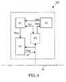
- the block diagram of Fig. 4illustrates a receiver 40 comprising a processing unit (CPU) 41, memory unit 42, HDLC receiver 43 and logical unit 44.
- the inputis from a HDLC uplink bus 45.
- the stop signal 46is directly connected to the uplink.
- the logic unit 44guarantees that the stop signal is only allowed between the frames.
- the logic unitoperates by monitoring the received data traffic and controls the stop signal from the CPU such that the blocking sequence is output only when the bus is inactive.
- the memory unitcomprises data received and interpreted by HDLC receiver. Clearly, this is one exemplary way of illustrating a receiver unit and other constructions may occur.
Landscapes
- Engineering & Computer Science (AREA)
- Computer Networks & Wireless Communication (AREA)
- Signal Processing (AREA)
- Computer Security & Cryptography (AREA)
- Theoretical Computer Science (AREA)
- Physics & Mathematics (AREA)
- General Engineering & Computer Science (AREA)
- General Physics & Mathematics (AREA)
- Communication Control (AREA)
Description
- The present invention relates to a method and arrangement for controlling dataflow on a data bus, especially for avoiding reception problems by a receiver unit, said databus connecting at least one receiver unit to one or several transmitter units.
- HDLC, High-level Data Link Control, is a popular ITU defined protocol used in data networking applications such as cellular base station switch controllers, frame relay switches, high bandwidth WAN links, xDSL and modem error correction. This protocol is responsible for transmitting data between network points. It organizes data into units, following the bit oriented packet transmission mode, and sends it across a network to a destination that verifies its successful arrival. The data stream and transmission rate is controlled from the network node (PCM highway clock) with a backpressure mechanism. This eliminates additional synchronization and buffering of the data at the network interface. Different variations of the protocol are used in different networks. For example, ISDN's D-channel uses a slightly modified version of HDLC
- There are many types of HDLC and examples given in the following description are merely for clarifying reasons and in no way limit the invention to the examples.
- HDLC uses the term "frame" to indicate an entity of data (or a protocol data unit) transmitted from one station to another. Fig. 1 is a graphical representation of a HDLC frame with an Information field.
- Every frame on the link must begin and end with a flag sequence field, F. Stations attached to the data link must continually listen for a flag sequence. The flag sequence can be an octet looking like 01111110. Flags are continuously transmitted on the link between frames to keep the link active. Two other bit sequences are used in HDLC as signals for the stations on the link. According to one exemplary embodiment, these two bit sequences are:
- Seven 1's, but less than 15 signals an abort signal. The stations on the link know there is a problem on the link.
- 15 or more 1's indicate that the channel is in an idle state.
- The time between the transmissions of actual frames is called the interframe time fill. The interframe time fill is accomplished by transmitting continuous flags between frames. The flags may be in 8 bit multiples.
- HDLC is a code-transparent protocol. It does not rely on a specific code for interpretation of line control. This means that a bit at position N in an octet has a specific meaning, regardless of the other bits in the same octet. If an octet has a bit sequence of 01111110, but is not a flag field, HDLC uses a technique called bit-stuffing to differentiate this bit sequence from a flag field. Once the transmitter detects that it is sending 5 consecutive 1's, in inserts a 0 bit to prevent a "phony" flag.
- When the above sequence is transmitted, at the receiving end, the receiving station inspects the incoming frame. If it detects 5 consecutive 1's it looks at the next bit. If it is a 0, it pulls it out. If it is a 1, it looks at the 8th bit. If the 8th bit is a 1, it knows that an abort or idle signal has been sent. It then proceeds to inspect the following bits to determine appropriate action. HDLC achieves code-transparency in this manner. HDLC is not concerned with any specific bit code inside the data stream. It is only concerned with keeping flags unique.
- Other fields comprise:
- A: Address field
- C: control field
- I: Information field, and
- CRC: Frame checking sequence.
- The functionality of HDLC and its different fields are assumed to be known for skilled persons and not described herein in more detail.
- During high loads on the bus, the routing function of the bus, i.e. the bus-master, will not function properly because its buffers become filled. Thus, the incoming traffic cannot be handled. To be able to stop the data from the slaves, i.e. the units transmitting data to the master, so that the buffers can be emptied a mechanism is needed.
- It is possible to use a separate stop signal as the flow control, as illustrated in fig. 2. Fig. 2 illustrates a simple data link comprising a number of Transmitters and a Receiver. The data flow is through an uplink bus. In case of an overflow state, the receiver signals the transmitters to stop sending data.
- In JP 10013878, a stable communication processing at all times by limiting received calls from an ISDN line network depending on a data transmission quantity of a data input system is attained. A main CPU of a control unit monitors a data transmission quantity of a data highway based on a residual capacity of a dual port RAM, and a main CPU of an ISDN line interface unit monitors a data transmission quantity of the data highway 13 based on a residual capacity of a dual port RAM. When the data transmission quantity of the data highway exceeds a prescribed quantity, either or both the main CPU and the main CPU give an input reject request to a line internal bus interface/HDLC controller of the ISDN line interface unit to allow the controller to send the call reception reject request to an ISDN line network thereby limiting the arrival of succeeding data and preventing overload of reception data input system, resulting in conducting stable communication processing.
- EP 647 082 concerns a data link controller (DLC), which employs buffers on both receiving and transmitting sides. These last-in, first-out buffers contain a position indicating that a character is the last one of a packet. In this way, a user need not monitor reception or transmission on a character-by-character basis, but need only concern themselves with packets. The receive and transmit FIFO's generate requests for more characters by monitoring the number of characters stored and thereby automatically receive and transmit characters without processor intervention. A four-stage mechanism permits monitoring of multiple contiguous frames (back-to-back frames) received. Control of the DLC is provided by status and control registers, which are accessible to the user via a microprocessor interface. Particular registers have bit positions monitoring status conditions in such a manner that the most-probable one of a set of conditions comprises the least-significant bit position, while the least-probable condition occupies the most-significant bit position. This affords simple shift and test technique for monitoring status conditions.
- US 5,878,279 relates to an integrated HDLC circuit of the type including at least one HDLC controller and one DMA controller, and means for organizing the access to a first external bus for connection to an external memory, via an internal bus to which are connected different entities, which require to have access to the external memory, the internal bus being connected to the first external bus via a memory controller integrated in the HDLC circuit.
- In US 5,410,542 a signal computing bus (SCbus) includes two bus structures: (a) a synchronous TDM data transport referred to as a data bus and (b) a serial message passing bus referred to as a message bus. The following three groups of functions are performed using the SCbus: (a) data transport over the data bus, (b) message passing over the message bus, and (c) data and message bus control. In a preferred embodiment, the data bus utilizes: 2 clocks, 1 frame pulse, 16 data busses, and 1 clock control (the clock control signal enables access to the bus and automatic switching from one clock master to another when an error is detected) and the message bus is fabricated using a master HDLC protocol with contention resolution.
- EP 238 255 relates to an interface arrangement, which interconnects a business communication system with a telephone station set. All signaling from the business communication system is received by the personal computer, interpreted, and appropriate control signals are then forwarded under control of the software resident on the personal computer to activate the digital telephone station set. The signals from the digital telephone station set are intercepted by the personal computer, interpreted, modified and appropriate control messages and signaling are then forwarded by the personal computer to the business communication system. This arrangement enables a user to create software on the personal computer to control the operation of the telephone station set associated with the personal computer.
- EP 1 014 626 relates to a method, apparatus and network device for controlling the flow of network data arranged in frames and minimizing congestion, such as in the receive port of an HDLC controller. The object is achieved by generating a status error indicator within a receive FIFO memory indicative of a frame overflow within the receive FIFO memory. In response to the status error indicator, an early congestion interrupt is generated to a host processor indicative that a frame overflow has occurred within the receive FIFO memory. The incoming frame is discrarded and the services of received frames are enhanced by one of either increasing the number of words of a direct memory access (DMA) unit burst size, or modifying the time-slice of other active processes.
- However, the present invention uses a part of the bus protocol to assume a collision to prohibit overflow.
- None of the cited documents use the technique of the Invention, as described In the following, to achieve an optimal flow control based on present protocols.
- What is needed is an arrangement and method for managing a flow control on data buses using collision control detection, especially but not exclusively a HDLC bus. The method according to the present invention allows an overflow and congestion elimination on the receiver side on a bus without using additional signals and additional protocols.
- Most generally, the object of the invention is to stop a flow of data to a bus master when the bus master's buffers are full and the master cannot handle incoming data.
- For these reasons the method comprises the steps of transmitting by said receiver unit on said databus a control data sequence to be received by said transmitting units, which alter transmission mode upon reception of said control data sequence.
- In the most preferred embodiment the transmission on said databus uses a High-level Data Link Control (HDLC) protocol. The mentioned data sequence comprises logical zeros (0) or ones (1).
- In one embodiment several receiver units are arranged and each receiver unit comprises a processing unit, a memory unit, a bus driver and a logical unit. Thus, the receiver unit is connected to the uplink databus and that a stop signal is directly connected to said uplink, whereby said logic unit guarantees that said stop signal is only allowed between data frames. The logic unit is arranged to monitor the received data traffic and control the stop signal from said processing unit, such that said control data sequence is output only when the bus is inactive.
- The transmission mode comprises one of transmission or blocked transmission for controlling overflow.
- The invention also relates to a method for controlling dataflow on a databus, especially for avoiding reception problems by a receiver unit. The databus connects at least one receiver unit to one or several transmitter units. The method comprises the steps of transmitting by said receiver unit on said databus a control data sequence to be received by said transmitting units, which alter a transmission mode upon reception of said control data sequence. To use standard available means, transmission on said databus uses a collision detection mechanism. Most preferably, the transmission on said databus uses a High-level Data Link Control (HDLC) protocol. The data sequence comprises logical zeros (0) or ones (1).
- The method further comprises the steps of: when the data traffic on said databus becomes so high that said receiver unit cannot handle the data, said data sequence is inserted in a data frame, such that when a transmitter unit, sending on said databus, receives the sequence it stops sending data. The transmitter stops sending data when it has transmitted its first logical one or zero. The transmission from a transmitter unit is stopped as long as the receiver unit outputs a different control data sequence on the databus, so that the transmitter units retransmit a stopped data message.
- In the following, the invention will be further described In a non-limiting way with reference to the accompanying drawings in which:
- Fig. 1
- schematically illustrates a frame structure of HDLC protocol,
- Fig. 2
- illustrates a coupling diagram using an additional control signal, according to prior art,
- Fig. 3
- illustrates a coupling diagram of an embodiment according to the present invention, and
- Fig. 4
- Illustrates a coupling diagram of a second embodiment according to the present invention.
- In the following the invention is described with reference to a preferred embodiment based on a data link using HDLC protocol. However, it is possible to implement the teachings of the invention in other link configurations having collision control detection ability, especially layer 2 links, such as SDLC, SS #7 (Signaling System No. 7), APPLETALK, LAPB (Link Access Procedure Balanced), LAPD (Link Access Protocol for D-Channel) etc., based on HDLC framing structure.
- The invention uses a surprising effect of a function, collision detection, imbedded in the HDLC protocol, Bus Mode. Collision detection is used to enable data transmission on the same bus to several transmitters without losing data.
- This is achieved by giving a bus master (receiver) the ability to send a blocking sequence on the bus. The blocking sequence is composed of zeros (or ones depending on the protocol configuration) and is detected by all transmitters, which will abort transmission. When the blocking sequence is completed, the transmitters will retransmit aborted transmissions. Thus, conventional components can be used for flow control.
- Fig. 3 is a schematic coupling diagram of a number of transmitters 10 (slaves) connected to a number of receivers 11 (masters). The
transmitters 10 andreceivers 11 are connected by means of adatabus 12. In the most preferred embodiment only one receiver is used. However, If several receivers are used, each receiver is provided with a unique address. - In the HDLC standard logical zeros are used as a control sequence and have higher priority than logical ones. According to the invention, when the data traffic on the bus becomes so high that the receiver cannot handle the data, e.g. when its buffers are filled, zeroes are inserted in the data frame and into the uplink databus. When a transmitter, sending on the bus, receives the sequence it will stop sending data when it has transmitted its first logical one. The transmitter assumes that a collision is detected on the bus, as the HDLC bus mode protocol standard.
- The transmission from a transmitter is stopped until the receiver no longer outputs zeroes on the bus. When the receiver stops sending zeros, the transmitters will retransmit the stopped data message, as a consequence of the HDLC protocol standards. Thus, no additional stop signals are needed or additional retransmission functions, which reduces the number of the connections and circuitry for handling overflow.
- If two or
more receivers 11 are used, each receiver must be able to stop the Incoming transmission individually, depending on its load. For this reason, a controlling logic must be provided to guarantee that the frames are not interrupted in an undesired way. Otherwise, the other receivers can interpret the stop sequence as a corrupted frame, which can be difficult to separate from an actual error. In a system with only one receiver, the interrupted frame is interpreted as incorrect but it is possible to distinguish it from a real Incorrectness. - The block diagram of Fig. 4 illustrates a
receiver 40 comprising a processing unit (CPU) 41,memory unit 42,HDLC receiver 43 andlogical unit 44. The input is from aHDLC uplink bus 45. Thestop signal 46 is directly connected to the uplink. Thelogic unit 44 guarantees that the stop signal is only allowed between the frames. The logic unit operates by monitoring the received data traffic and controls the stop signal from the CPU such that the blocking sequence is output only when the bus is inactive. The memory unit comprises data received and interpreted by HDLC receiver. Clearly, this is one exemplary way of illustrating a receiver unit and other constructions may occur. - The invention is not limited to the shown embodiments but can be varied in a number of ways without departing from the scope of the appended claims and the arrangement and the method can be implemented in various ways depending on application, functional units, needs and requirements etc.
Claims (15)
- A databus controller arrangement for controlling data flow on a databus (12), said databus connecting at least one receiver unit (11) to at least one transmitter unit (10), said arrangement, being a part of said receiver unit (11), being arranged to control said flow, specially an overflow, on said databus by outputting a control data sequence on said databus to be received by said at least one transmitter unit, which is arranged to alter transmission mode upon reception of said control data sequence
characterized in
that said data sequence is a blocking sequence for collision detection. - The arrangement of claim 1,
characterized in
that said transmission on said databus uses a High-level Data Link Control (HDLC) protocol. - The arrangement of claim 1 or 2,
characterized in
that said data sequence comprises logical zeros (0) or ones (1). - The arrangement according to any of claims 1-3,
characterized in
that several receiver units are arranged and that each receiver unit (40) comprises a processing unit (41), a memory unit (42), a bus driver (43) and a logical unit (44). - The arrangement of claim 4,
characterized in
that said receiver unit is connected to uplink databus (45) and that a stop signal (46) is directly connected to said uplink, whereby said logic unit (44) guarantees that said stop signal is only allowed between data frames. - The arrangement of claim 5,
characterized In
that said logic unit is arranged to monitor the received data traffic and control the stop signal from said processing unit, such that said control data sequence is output only when the bus is inactive. - The arrangement according to any of claims 1-6,
characterized in
that said transmission mode comprises one of transmission or blocked transmission. - A method for controlling dataflow on a databus, especially for avoiding reception problems by a receiver unit, said databus (12) connecting at least one receiver unit (11) to one or several transmitter units (11), the method comprising the steps of transmitting by said receiver unit on said databus a control data sequence, being a blocking sequence for collision detection, to be received by said transmitting units, which alter a transmission mode upon reception of said control data sequence.
- The method of claim 8, wherein said transmission on said databus uses a collision detection mechanism.
- The method of claim 8 or 9, wherein said transmission on said databus uses a High-level Data Link Control (HDLC) protocol.
- The method according to any of claims 8 - 10, wherein said data sequence comprises logical zeros (0) or ones (1).
- The method according to claim 8, wherein when the data traffic on said databus becomes so high that said receiver unit cannot handle the data, said data sequence is inserted in a data frame, such that when a transmitter unit, sending on said databus, receives the sequence it stops sending data.
- The method according to claim 8, wherein said transmitter stops sending data when it has transmitted its first logical one or zero.
- The method according to claim 13, wherein the transmission from a transmitter unit is stopped as long as the receiver unit outputs a different control data sequence on the databus, so that the transmitter units retransmit a stopped data message.
- The method according to any of claims 8-14, wherein said transmission mode comprises one of transmission or blocked transmission.
Priority Applications (1)
| Application Number | Priority Date | Filing Date | Title |
|---|---|---|---|
| AT02773073TATE335238T1 (en) | 2002-09-16 | 2002-09-16 | BUS TAX ARRANGEMENT AND PROCEDURES |
Applications Claiming Priority (1)
| Application Number | Priority Date | Filing Date | Title |
|---|---|---|---|
| PCT/SE2002/001672WO2004025487A1 (en) | 2002-09-16 | 2002-09-16 | Bus control arrangement and method |
Publications (2)
| Publication Number | Publication Date |
|---|---|
| EP1540484A1 EP1540484A1 (en) | 2005-06-15 |
| EP1540484B1true EP1540484B1 (en) | 2006-08-02 |
Family
ID=31989563
Family Applications (1)
| Application Number | Title | Priority Date | Filing Date |
|---|---|---|---|
| EP02773073AExpired - LifetimeEP1540484B1 (en) | 2002-09-16 | 2002-09-16 | Bus control arrangement and method |
Country Status (5)
| Country | Link |
|---|---|
| US (1) | US7206881B2 (en) |
| EP (1) | EP1540484B1 (en) |
| AU (1) | AU2002337537A1 (en) |
| DE (1) | DE60213680T2 (en) |
| WO (1) | WO2004025487A1 (en) |
Families Citing this family (1)
| Publication number | Priority date | Publication date | Assignee | Title |
|---|---|---|---|---|
| DE10337699B4 (en)* | 2003-08-16 | 2006-01-12 | Phoenix Contact Gmbh & Co. Kg | Method and device for transmitting data over a bus network using the broadcast principle |
Family Cites Families (18)
| Publication number | Priority date | Publication date | Assignee | Title |
|---|---|---|---|---|
| US4261035A (en)* | 1979-09-28 | 1981-04-07 | Honeywell Information Systems Inc. | Broadband high level data link communication line adapter |
| US4748656A (en) | 1986-03-21 | 1988-05-31 | American Telephone And Telegraph Company | Personal computer--as an interface between a telephone station set and a business communication system |
| US5007051A (en)* | 1987-09-30 | 1991-04-09 | Hewlett-Packard Company | Link layer protocol and apparatus for data communication |
| US5412782A (en)* | 1992-07-02 | 1995-05-02 | 3Com Corporation | Programmed I/O ethernet adapter with early interrupts for accelerating data transfer |
| US5299313A (en)* | 1992-07-28 | 1994-03-29 | 3Com Corporation | Network interface with host independent buffer management |
| DE69330399T2 (en)* | 1992-12-18 | 2002-05-02 | Advanced Micro Devices, Inc. | HDLC receiver |
| IT1261596B (en) | 1993-09-30 | 1996-05-23 | Marelli Autronica | CONTROL CIRCUIT FOR A GAS DISCHARGE LAMP, PARTICULARLY FOR VEHICLES. |
| US6026088A (en)* | 1993-10-20 | 2000-02-15 | Lsi Logic Corporation | Network architecture |
| US5473604A (en)* | 1994-11-21 | 1995-12-05 | At&T Corp. | Method for avoiding node overload in a packet switching network |
| US6351780B1 (en)* | 1994-11-21 | 2002-02-26 | Cirrus Logic, Inc. | Network controller using held data frame monitor and decision logic for automatically engaging DMA data transfer when buffer overflow is anticipated |
| FR2737592B1 (en)* | 1995-08-03 | 1997-10-17 | Sgs Thomson Microelectronics | HDLC CIRCUIT WITH SHARED INTERNAL BUS |
| JPH1013878A (en) | 1996-06-26 | 1998-01-16 | Toshiba Corp | Key telephone equipment |
| US6031843A (en)* | 1996-11-21 | 2000-02-29 | Alcatel Data Networks Inc. | Digital communications switching fabric |
| US6307835B1 (en)* | 1998-07-10 | 2001-10-23 | Stmicroelectronics, Inc. | Method and apparatus for controlling data flow in data communication networks |
| US6717910B1 (en)* | 1998-09-30 | 2004-04-06 | Stmicroelectronics, Inc. | Method and apparatus for controlling network data congestion |
| US6356962B1 (en)* | 1998-09-30 | 2002-03-12 | Stmicroelectronics, Inc. | Network device and method of controlling flow of data arranged in frames in a data-based network |
| US6625163B1 (en)* | 1999-04-21 | 2003-09-23 | Nortel Networks Ltd. | Collision detection on a differential bus |
| US6967950B2 (en)* | 2000-08-11 | 2005-11-22 | Texas Instruments Incorporated | Pull transfers and transfer receipt confirmation in a datapipe routing bridge |
- 2002
- 2002-09-16EPEP02773073Apatent/EP1540484B1/ennot_activeExpired - Lifetime
- 2002-09-16USUS10/528,064patent/US7206881B2/ennot_activeExpired - Fee Related
- 2002-09-16DEDE60213680Tpatent/DE60213680T2/ennot_activeExpired - Fee Related
- 2002-09-16WOPCT/SE2002/001672patent/WO2004025487A1/ennot_activeApplication Discontinuation
- 2002-09-16AUAU2002337537Apatent/AU2002337537A1/ennot_activeAbandoned
Also Published As
| Publication number | Publication date |
|---|---|
| US7206881B2 (en) | 2007-04-17 |
| WO2004025487A1 (en) | 2004-03-25 |
| US20060155901A1 (en) | 2006-07-13 |
| DE60213680D1 (en) | 2006-09-14 |
| EP1540484A1 (en) | 2005-06-15 |
| DE60213680T2 (en) | 2007-06-14 |
| AU2002337537A1 (en) | 2004-04-30 |
Similar Documents
| Publication | Publication Date | Title |
|---|---|---|
| EP0525985B1 (en) | High speed duplex data link interface | |
| EP0042447B1 (en) | Flow control mechanism for block switching nodes | |
| EP0582537A2 (en) | Transmission of high-priority, real-time traffic on low-speed communications links | |
| EP0333225A2 (en) | Packet communication exchange including dummy packet transmission | |
| JPH0771125B2 (en) | Data communication method and data communication system | |
| JPS6158062B2 (en) | ||
| JPS60250799A (en) | Electric communication switching circuit network and its operating method | |
| US6680910B1 (en) | Network interface unit | |
| JPS6342543A (en) | Packet flow controlling system | |
| US7130271B1 (en) | Relaying apparatus | |
| EP0899899B1 (en) | An apparatus and method for sharing a signaling channel | |
| EP1540484B1 (en) | Bus control arrangement and method | |
| US20080205567A1 (en) | Methods and Receives of Data Transmission Using Clock Domains | |
| US6219416B1 (en) | Method and apparatus for processing FISU frames according to the Signalling System 7 protocol | |
| CN1184779C (en) | Relay system used for digital communication | |
| US5469472A (en) | Message substitution in a digital communication system | |
| US20020161912A1 (en) | Ethernet cross point switch for connecting multiple network sections with different speeds within physical layer protocol | |
| KR100249512B1 (en) | Rate control method using backward explicit congestion notification bit in frame relay network matching device | |
| JPH063925B2 (en) | Shared channel access control circuit | |
| JPH04361447A (en) | Inter-network connector and its control method | |
| FI109074B (en) | Abonnentmultiplexeringsanordning | |
| JP2655872B2 (en) | Flow control method | |
| JP2929832B2 (en) | Statistical packet multiplexing method | |
| JP2004007848A (en) | Flow control method and system | |
| JPS6376647A (en) | Packet flow rate restriction method |
Legal Events
| Date | Code | Title | Description |
|---|---|---|---|
| PUAI | Public reference made under article 153(3) epc to a published international application that has entered the european phase | Free format text:ORIGINAL CODE: 0009012 | |
| 17P | Request for examination filed | Effective date:20050312 | |
| AK | Designated contracting states | Kind code of ref document:A1 Designated state(s):AT BE BG CH CY CZ DE DK EE ES FI FR GB GR IE IT LI LU MC NL PT SE SK TR | |
| AX | Request for extension of the european patent | Extension state:AL LT LV MK RO SI | |
| RIN1 | Information on inventor provided before grant (corrected) | Inventor name:JOHANSSON, MATTIAS Inventor name:CEDERLOEF, MANS | |
| DAX | Request for extension of the european patent (deleted) | ||
| GRAP | Despatch of communication of intention to grant a patent | Free format text:ORIGINAL CODE: EPIDOSNIGR1 | |
| GRAS | Grant fee paid | Free format text:ORIGINAL CODE: EPIDOSNIGR3 | |
| GRAA | (expected) grant | Free format text:ORIGINAL CODE: 0009210 | |
| RAP1 | Party data changed (applicant data changed or rights of an application transferred) | Owner name:TELEFONAKTIEBOLAGET LM ERICSSON (PUBL) | |
| AK | Designated contracting states | Kind code of ref document:B1 Designated state(s):AT BE BG CH CY CZ DE DK EE ES FI FR GB GR IE IT LI LU MC NL PT SE SK TR | |
| PG25 | Lapsed in a contracting state [announced via postgrant information from national office to epo] | Ref country code:IT Free format text:LAPSE BECAUSE OF FAILURE TO SUBMIT A TRANSLATION OF THE DESCRIPTION OR TO PAY THE FEE WITHIN THE PRESCRIBED TIME-LIMIT;WARNING: LAPSES OF ITALIAN PATENTS WITH EFFECTIVE DATE BEFORE 2007 MAY HAVE OCCURRED AT ANY TIME BEFORE 2007. THE CORRECT EFFECTIVE DATE MAY BE DIFFERENT FROM THE ONE RECORDED. Effective date:20060802 Ref country code:CZ Free format text:LAPSE BECAUSE OF FAILURE TO SUBMIT A TRANSLATION OF THE DESCRIPTION OR TO PAY THE FEE WITHIN THE PRESCRIBED TIME-LIMIT Effective date:20060802 Ref country code:NL Free format text:LAPSE BECAUSE OF FAILURE TO SUBMIT A TRANSLATION OF THE DESCRIPTION OR TO PAY THE FEE WITHIN THE PRESCRIBED TIME-LIMIT Effective date:20060802 Ref country code:AT Free format text:LAPSE BECAUSE OF FAILURE TO SUBMIT A TRANSLATION OF THE DESCRIPTION OR TO PAY THE FEE WITHIN THE PRESCRIBED TIME-LIMIT Effective date:20060802 Ref country code:LI Free format text:LAPSE BECAUSE OF FAILURE TO SUBMIT A TRANSLATION OF THE DESCRIPTION OR TO PAY THE FEE WITHIN THE PRESCRIBED TIME-LIMIT Effective date:20060802 Ref country code:BE Free format text:LAPSE BECAUSE OF FAILURE TO SUBMIT A TRANSLATION OF THE DESCRIPTION OR TO PAY THE FEE WITHIN THE PRESCRIBED TIME-LIMIT Effective date:20060802 Ref country code:SK Free format text:LAPSE BECAUSE OF FAILURE TO SUBMIT A TRANSLATION OF THE DESCRIPTION OR TO PAY THE FEE WITHIN THE PRESCRIBED TIME-LIMIT Effective date:20060802 Ref country code:CH Free format text:LAPSE BECAUSE OF FAILURE TO SUBMIT A TRANSLATION OF THE DESCRIPTION OR TO PAY THE FEE WITHIN THE PRESCRIBED TIME-LIMIT Effective date:20060802 Ref country code:FI Free format text:LAPSE BECAUSE OF FAILURE TO SUBMIT A TRANSLATION OF THE DESCRIPTION OR TO PAY THE FEE WITHIN THE PRESCRIBED TIME-LIMIT Effective date:20060802 | |
| REG | Reference to a national code | Ref country code:GB Ref legal event code:FG4D | |
| REG | Reference to a national code | Ref country code:CH Ref legal event code:EP | |
| REG | Reference to a national code | Ref country code:IE Ref legal event code:FG4D | |
| REF | Corresponds to: | Ref document number:60213680 Country of ref document:DE Date of ref document:20060914 Kind code of ref document:P | |
| PG25 | Lapsed in a contracting state [announced via postgrant information from national office to epo] | Ref country code:IE Free format text:LAPSE BECAUSE OF NON-PAYMENT OF DUE FEES Effective date:20060918 | |
| PG25 | Lapsed in a contracting state [announced via postgrant information from national office to epo] | Ref country code:MC Free format text:LAPSE BECAUSE OF NON-PAYMENT OF DUE FEES Effective date:20060930 | |
| PG25 | Lapsed in a contracting state [announced via postgrant information from national office to epo] | Ref country code:SE Free format text:LAPSE BECAUSE OF FAILURE TO SUBMIT A TRANSLATION OF THE DESCRIPTION OR TO PAY THE FEE WITHIN THE PRESCRIBED TIME-LIMIT Effective date:20061102 Ref country code:DK Free format text:LAPSE BECAUSE OF FAILURE TO SUBMIT A TRANSLATION OF THE DESCRIPTION OR TO PAY THE FEE WITHIN THE PRESCRIBED TIME-LIMIT Effective date:20061102 Ref country code:BG Free format text:LAPSE BECAUSE OF FAILURE TO SUBMIT A TRANSLATION OF THE DESCRIPTION OR TO PAY THE FEE WITHIN THE PRESCRIBED TIME-LIMIT Effective date:20061102 | |
| PG25 | Lapsed in a contracting state [announced via postgrant information from national office to epo] | Ref country code:ES Free format text:LAPSE BECAUSE OF FAILURE TO SUBMIT A TRANSLATION OF THE DESCRIPTION OR TO PAY THE FEE WITHIN THE PRESCRIBED TIME-LIMIT Effective date:20061113 | |
| NLV1 | Nl: lapsed or annulled due to failure to fulfill the requirements of art. 29p and 29m of the patents act | ||
| PG25 | Lapsed in a contracting state [announced via postgrant information from national office to epo] | Ref country code:PT Free format text:LAPSE BECAUSE OF FAILURE TO SUBMIT A TRANSLATION OF THE DESCRIPTION OR TO PAY THE FEE WITHIN THE PRESCRIBED TIME-LIMIT Effective date:20070102 | |
| REG | Reference to a national code | Ref country code:CH Ref legal event code:PL | |
| ET | Fr: translation filed | ||
| PG25 | Lapsed in a contracting state [announced via postgrant information from national office to epo] | Ref country code:DE Free format text:LAPSE BECAUSE OF NON-PAYMENT OF DUE FEES Effective date:20070403 | |
| PLBE | No opposition filed within time limit | Free format text:ORIGINAL CODE: 0009261 | |
| STAA | Information on the status of an ep patent application or granted ep patent | Free format text:STATUS: NO OPPOSITION FILED WITHIN TIME LIMIT | |
| 26N | No opposition filed | Effective date:20070503 | |
| REG | Reference to a national code | Ref country code:FR Ref legal event code:ST Effective date:20080131 | |
| PG25 | Lapsed in a contracting state [announced via postgrant information from national office to epo] | Ref country code:GR Free format text:LAPSE BECAUSE OF FAILURE TO SUBMIT A TRANSLATION OF THE DESCRIPTION OR TO PAY THE FEE WITHIN THE PRESCRIBED TIME-LIMIT Effective date:20061103 | |
| PGFP | Annual fee paid to national office [announced via postgrant information from national office to epo] | Ref country code:FR Payment date:20070917 Year of fee payment:6 | |
| PG25 | Lapsed in a contracting state [announced via postgrant information from national office to epo] | Ref country code:EE Free format text:LAPSE BECAUSE OF FAILURE TO SUBMIT A TRANSLATION OF THE DESCRIPTION OR TO PAY THE FEE WITHIN THE PRESCRIBED TIME-LIMIT Effective date:20060802 | |
| PG25 | Lapsed in a contracting state [announced via postgrant information from national office to epo] | Ref country code:LU Free format text:LAPSE BECAUSE OF NON-PAYMENT OF DUE FEES Effective date:20060916 Ref country code:FR Free format text:LAPSE BECAUSE OF NON-PAYMENT OF DUE FEES Effective date:20061002 Ref country code:TR Free format text:LAPSE BECAUSE OF FAILURE TO SUBMIT A TRANSLATION OF THE DESCRIPTION OR TO PAY THE FEE WITHIN THE PRESCRIBED TIME-LIMIT Effective date:20060802 | |
| PG25 | Lapsed in a contracting state [announced via postgrant information from national office to epo] | Ref country code:CY Free format text:LAPSE BECAUSE OF FAILURE TO SUBMIT A TRANSLATION OF THE DESCRIPTION OR TO PAY THE FEE WITHIN THE PRESCRIBED TIME-LIMIT Effective date:20060802 | |
| PGFP | Annual fee paid to national office [announced via postgrant information from national office to epo] | Ref country code:GB Payment date:20150928 Year of fee payment:14 | |
| PG25 | Lapsed in a contracting state [announced via postgrant information from national office to epo] | Ref country code:FR Free format text:LAPSE BECAUSE OF NON-PAYMENT OF DUE FEES Effective date:20070930 | |
| GBPC | Gb: european patent ceased through non-payment of renewal fee | Effective date:20160916 | |
| PG25 | Lapsed in a contracting state [announced via postgrant information from national office to epo] | Ref country code:GB Free format text:LAPSE BECAUSE OF NON-PAYMENT OF DUE FEES Effective date:20160916 |