EP1540180B1 - Electronic fluid pump - Google Patents
Electronic fluid pumpDownload PDFInfo
- Publication number
- EP1540180B1 EP1540180B1EP03765450AEP03765450AEP1540180B1EP 1540180 B1EP1540180 B1EP 1540180B1EP 03765450 AEP03765450 AEP 03765450AEP 03765450 AEP03765450 AEP 03765450AEP 1540180 B1EP1540180 B1EP 1540180B1
- Authority
- EP
- European Patent Office
- Prior art keywords
- diffuser
- pump
- fluid pump
- tubular member
- fluid
- Prior art date
- Legal status (The legal status is an assumption and is not a legal conclusion. Google has not performed a legal analysis and makes no representation as to the accuracy of the status listed.)
- Expired - Lifetime
Links
- 239000012530fluidSubstances0.000titleclaimsdescription76
- 239000000853adhesiveSubstances0.000claimsdescription5
- 230000001070adhesive effectEffects0.000claimsdescription5
- 239000000463materialSubstances0.000claimsdescription3
- 238000005086pumpingMethods0.000claimsdescription3
- 239000013536elastomeric materialSubstances0.000claimsdescription2
- 229910010293ceramic materialInorganic materials0.000claims1
- 239000000919ceramicSubstances0.000description10
- 238000000034methodMethods0.000description6
- 238000001816coolingMethods0.000description4
- 230000008878couplingEffects0.000description4
- 238000010168coupling processMethods0.000description4
- 238000005859coupling reactionMethods0.000description4
- 238000004804windingMethods0.000description3
- 230000008901benefitEffects0.000description2
- 229920001940conductive polymerPolymers0.000description2
- 239000002826coolantSubstances0.000description2
- 239000007788liquidSubstances0.000description2
- 230000008569processEffects0.000description2
- RYGMFSIKBFXOCR-UHFFFAOYSA-NCopperChemical compound[Cu]RYGMFSIKBFXOCR-UHFFFAOYSA-N0.000description1
- CWYNVVGOOAEACU-UHFFFAOYSA-NFe2+Chemical compound[Fe+2]CWYNVVGOOAEACU-UHFFFAOYSA-N0.000description1
- 229910000831SteelInorganic materials0.000description1
- 238000004026adhesive bondingMethods0.000description1
- 239000000356contaminantSubstances0.000description1
- 229910052802copperInorganic materials0.000description1
- 239000010949copperSubstances0.000description1
- 230000003247decreasing effectEffects0.000description1
- 239000000428dustSubstances0.000description1
- 230000005672electromagnetic fieldEffects0.000description1
- 230000008030eliminationEffects0.000description1
- 238000003379elimination reactionMethods0.000description1
- 230000006698inductionEffects0.000description1
- 238000003475laminationMethods0.000description1
- 239000000314lubricantSubstances0.000description1
- 239000000696magnetic materialSubstances0.000description1
- 239000002184metalSubstances0.000description1
- 229910052751metalInorganic materials0.000description1
- 238000000465mouldingMethods0.000description1
- 230000002028prematureEffects0.000description1
- 230000009467reductionEffects0.000description1
- 229910001220stainless steelInorganic materials0.000description1
- 239000010935stainless steelSubstances0.000description1
- 239000010959steelSubstances0.000description1
Images


Classifications
- F—MECHANICAL ENGINEERING; LIGHTING; HEATING; WEAPONS; BLASTING
- F04—POSITIVE - DISPLACEMENT MACHINES FOR LIQUIDS; PUMPS FOR LIQUIDS OR ELASTIC FLUIDS
- F04D—NON-POSITIVE-DISPLACEMENT PUMPS
- F04D29/00—Details, component parts, or accessories
- F04D29/40—Casings; Connections of working fluid
- F04D29/42—Casings; Connections of working fluid for radial or helico-centrifugal pumps
- F04D29/44—Fluid-guiding means, e.g. diffusers
- F04D29/445—Fluid-guiding means, e.g. diffusers especially adapted for liquid pumps
- F04D29/448—Fluid-guiding means, e.g. diffusers especially adapted for liquid pumps bladed diffusers
- F—MECHANICAL ENGINEERING; LIGHTING; HEATING; WEAPONS; BLASTING
- F04—POSITIVE - DISPLACEMENT MACHINES FOR LIQUIDS; PUMPS FOR LIQUIDS OR ELASTIC FLUIDS
- F04D—NON-POSITIVE-DISPLACEMENT PUMPS
- F04D13/00—Pumping installations or systems
- F04D13/02—Units comprising pumps and their driving means
- F04D13/06—Units comprising pumps and their driving means the pump being electrically driven
- F04D13/0606—Canned motor pumps
- F04D13/0633—Details of the bearings
- F—MECHANICAL ENGINEERING; LIGHTING; HEATING; WEAPONS; BLASTING
- F04—POSITIVE - DISPLACEMENT MACHINES FOR LIQUIDS; PUMPS FOR LIQUIDS OR ELASTIC FLUIDS
- F04D—NON-POSITIVE-DISPLACEMENT PUMPS
- F04D3/00—Axial-flow pumps
Definitions
- the present inventionrelates to an electronic fluid pump.
- a coolant pumphas a pulley keyed to a shaft.
- the shaftis driven by the engine via a belt and pulley coupling, and rotates an impeller to pump the working fluid.
- Fluid sealssometimes fail due to the side load from the drive belt, which tends to allow fluid to leak past the seal into the bearing.
- Industrial pumpsare typically driven by an electric motor connected to the pump via a coupling, the alignment of which is critical. Misalignment of the coupling can result in premature pump failure, which leads to the use of expensive constant velocity couplings to overcome this problem.
- industrial pump motorsare typically air-cooled, relying on air from the surrounding environment. The cooling air is drawn through the motor housing leaving airborne dust and other contaminants deposited in the motor components. These deposits can contaminate the bearings, causing them to fail, or the deposits can coat the windings, shielding them from the cooling air and causing the windings to overheat and short out.
- One aspect of the present inventionprovides a fluid pump, comprising:
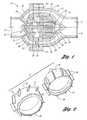
- FIG 1shows a side sectional view of a fluid pump 10 in accordance with the present invention.
- the fluid pump 10has a housing 12 that has an inlet 14 and an outlet 16.
- the housing 12defines an internal housing cavity 18 in which a diffuser 20 is located.
- the diffuser 20 shown in Figure 1includes a front portion 22, a middle portion sub-assembly 24, and a back portion 26.
- the middle portion sub-assembly 24 of the diffuser 20includes a vaned inner portion 25 and a diffuser ring 28.
- the diffuser ring 28is shrunk-fit to the vaned inner portion 25 to create the middle portion sub-assembly 24.
- the diffuser ring 28is captured between front and back pieces 30, 32 of the housing 12. Because the front and back portions 22, 26 of the diffuser 20 are connected to the middle portion sub-assembly 24, the diffuser 20 is held stationary within the housing cavity 18.
- the diffuser 20is shown in Figure 1 with a three-piece configuration, it can also be made from two pieces.
- Figure 2shows a two-piece diffuser 27, including a front portion 29 having vanes 31, and a back portion 33 having vanes 35.
- the diffuser ringis removed in this view to more clearly illustrate the diffuser vanes 31.
- the vanes 31, 35are configured to optimize fluid flow through the pump 10, and in particular, to straighten the fluid prior its leaving the outlet 16 (see Figure 1).
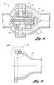
- the canister 40has a hollow cylindrical portion 42 that has an opening 44 surrounded by a lip 46.
- the canister 40is made from a non-magnetic material and is thin so as to minimize eddy current braking losses.
- the canister 40may be made from drawn stainless steel that has a wall thickness of 0.18 - 0.38 mm (0.007 - 0.015 inches).
- the generally cylindrical shape of the canister 40is well suited to the drawing process. It is understood however, that the canister 40 can be manufactured by processes other than deep drawing.
- the canister 40may be a tubular member open at both ends. Shown partially in phantom in Figure 4 is a tubular member 47 having both ends open. Such a configuration requires the tubular member 47 to be sealed against the diffuser 20 at the inlet and outlet sides to ensure that the stator assembly 26 remains isolated from the working fluid.
- a rotor assembly 48which includes a rotor 50 attached to a rotor shaft 52 is disposed within the canister 40. Attached to the rotor shaft 52 are bearings 54, 56 which support the rotor assembly 48.
- the stator assembly 36When power is provided to the pump 10, the stator assembly 36 generates a magnetic field which causes the rotor 50, and therefore the rotor shaft 52, to rotate.
- the rotation of the rotor shaft 52turns an impeller 58 that is attached to one end of the rotor shaft 52.
- the impeller 58shown in detail in Figure 3, includes vanes 59 configured to pump the fluid from the inlet 14 to the outlet 16 as the impeller 58 rotates.
- the stator assembly 36 and the rotor assembly 48comprise the pump motor, which can be configured in a variety of ways to suit the requirements of different applications.
- the rotorcan be a magnet, if a brushless permanent magnet pump motor is desired.
- the pumpcan be driven by a switched reluctance motor, in which case the rotor 50 may be made of any ferrous metal (for example, see U.S. Patent No.6, 056, 518, describing a fluid pump using a switched reluctance motor.) Pumps using switched reluctance motors are particularly well suited to high temperature applications.
- the pump 10can be configured with many different types and sizes of pump motors, it can be used in a wide variety of applications.
- the pump motorwhen used in an automotive application, the pump motor can be powered by a low voltage DC power source.
- Small pumpssuch as this may be configured to have relatively low volumetric flow rates (40 gallons per minute (gpm) or less), with output pressures of less than two pounds per square inch (psi).
- the pump 10can be configured for a heavy-duty industrial application, in which case it may be driven by a three-phase induction motor with a high voltage AC power supply.
- a large industrial pumpsuch as this can be configured to pump over 500 gpm at 25 psi.
- a fluid pump 60is configured substantially the same as the fluid pump 10 in Figure 1. However, the seal between the canister 62 and the diffuser 64 is accomplished not with an adhesive, but rather with an elastomeric material such as an O-ring 66 located in a groove 68 molded into the diffuser 64.
- the canisterWhen an O-ring seal such as that shown in Figure 5 is used to isolate a stator assembly from the working fluid, the canister may be attached to the diffuser with an adhesive, or even threaded fasteners. Moreover, it is also possible to press fit the canister into the diffuser and thereby form a secure attachment. Adhesive bonding between the canister and the diffuser is another option. The methods described herein merely represent a few of the possible ways of attaching the canister and forming a seal to isolate the stator assembly.
- both of the bearings 54, 56are on the inlet side of the rotor 50.
- bearingsmay be positioned such that the rotor shaft is simply supported, rather than cantilevered.
- the fluid pump 70 shown in Figure 6has a rotor assembly 72 that includes a rotor 74 attached to a rotor shaft 75.
- one bearing 76attaches to the rotor shaft 75 on the inlet side of the rotor 74, while a second bearing 78 attaches to the rotor shaft 75 on the outlet side of the rotor 74.
- a rotor assembly used in the present inventionmay be supported in a number of ways depending on the needs of a particular application.
- the wear on the rotor shaft 86will be minimized as the working fluid acts as a lubricant at the interface of the bushings 82, 84 and the rotor shaft 86.
- Figure 8shows another embodiment 90 of the present invention.
- the fluid pump 90has a rotor assembly 92 that includes a rotor 94 and a rotor shaft 96.
- a rotor assembly 92that includes a rotor 94 and a rotor shaft 96.
- ceramic bushings 98, 100keep the rotor 94 centered within a canister 102, and keep the rotor 94 from moving front to back.
- the bushings 98, 100do not provide support for the rotor 94 during operation of the pump 90. Instead, the rotor 94 floats within the electromagnetic field generated by a stator assembly 103.
- This designeliminates losses due to friction that occur when bearings or bushings are used to support the rotor shaft.
- the rotoris not actually in contact with the bushings 98, 100 while it is rotating, there is virtually no wear on the bushings 98
- electrical wires for both power and motor controlwill connect to portions of the stator assembly 36 and exit the pump housing 12 at or near the circumferential portion 28. Typically these wires will not be terminated, so as to allow for easy attachment to any kind of electrical connection required by the particular application.
- An alternative to having unterminated electrical wires exit the housing 12is illustrated in Figure 9.
- a portion of a pump housing 104is shown with a threaded stud terminal 106 attached.
- the stud terminal 106is shown in detail in Figure 10.
- the stud terminal 106comprises a threaded stud 108 that traverses the pump housing 104 through an opening 110 in which there is placed a rubber grommet 112.
- a nut 114is threaded onto the threaded stud 108 from the outside of the pump housing 104. This not only holds the threaded stud 108 in place, but also helps to seal the opening 110 so that the working fluid does not escape the housing 104.
- the threaded stud 108is electrically connected to a stator assembly such as 36 shown in Figure 1.
- the stud terminal 106provides a convenient method to attach the electric power and motor control circuits to the fluid pump.
- a typical fluid pump such as 10 shown in Figure 1will have eight wires connected to the stator assembly that either exit the pump housing with unterminated ends, or are each attached inside the pump housing to a stud terminal such as 106 shown in Figures 9 and 10.
- the number of wires connected to the stator assemblymay be more or less than eight, depending on the particular application or applications for which the pump is configured.
- One way to reduce the number of wires leaving the pump housing or the number of stud terminals attached to the housing,is to integrate a motor controller into the fluid pump itself.
- a portion of a fluid pump 114is shown with a portion of a pump housing 116 having a housing cavity 118 in which there is a portion of a diffuser 120.
- a stator assembly 122is attached to, or integrally molded with, a portion of the diffuser 120.
- a controller 124is also attached to, or integrally molded with, a portion of the diffuser 120.
- a canister 126forms a seal with the diffuser 120 to isolate both the stator assembly 122 and the controller 124 from the working fluid.
- the portion of the diffuser 120 in contact with the stator assembly 122 and the controller 124can be made from a thermally conductive polymer which allows heat transfer from both the stator assembly 122 and the controller 124 to the working fluid.
- the controller 124by locating the controller 124 inside the pump and connecting it directly to the stator assembly 122, the possibility of having problems with the motor control due to electromagnetic interference (EMI) is greatly reduced or eliminated.
- EMIelectromagnetic interference
- integrating the controller 124 into the pumpreduces the number of wires or stud terminals exiting the pump housing 116, and it makes the entire pump design more compact. It is contemplated that in some applications the fluid pump of the present invention will be integrated into a system that has its own controller used to control other elements within the system.
- the system controllermay be configured to perform the additional task of controlling the fluid pump.
- the integrated controller configuration shown in Figure 11is a convenient method for providing a fluid pump and controller in one compact package.
Landscapes
- Engineering & Computer Science (AREA)
- Mechanical Engineering (AREA)
- General Engineering & Computer Science (AREA)
- Structures Of Non-Positive Displacement Pumps (AREA)
Description
- The present invention relates to an electronic fluid pump.
- Use of fluid pumps in vehicle engine cooling systems and various industrial applications is well known. However, typical fluid pumps in both of these areas have inherent limitations. Typically in engine cooling systems, a coolant pump has a pulley keyed to a shaft. The shaft is driven by the engine via a belt and pulley coupling, and rotates an impeller to pump the working fluid. Fluid seals sometimes fail due to the side load from the drive belt, which tends to allow fluid to leak past the seal into the bearing.
- U.S. Patent No. 6,056,518, issued to Allen et al. on May 2, 2000, describes one attempt to overcome the shortcomings of prior art vehicle coolant pumps. The '518 patent provides a fluid pump with a switched reluctance motor that is secured to a housing and rotates an impeller for pumping the fluid. This design eliminates the side load problem associated with keyed pulleys, but it is generally not intended for use where larger industrial pumps are required.
- Industrial pumps are typically driven by an electric motor connected to the pump via a coupling, the alignment of which is critical. Misalignment of the coupling can result in premature pump failure, which leads to the use of expensive constant velocity couplings to overcome this problem. Moreover, industrial pump motors are typically air-cooled, relying on air from the surrounding environment. The cooling air is drawn through the motor housing leaving airborne dust and other contaminants deposited in the motor components. These deposits can contaminate the bearings, causing them to fail, or the deposits can coat the windings, shielding them from the cooling air and causing the windings to overheat and short out.
- Another known fluid pump is described in US5494418. This discloses a fluid pump driven by an electric motor having a stator assembly disposed within a diffuser cavity of the pump. The stator assembly is isolated from the pumped fluid by a tubular member within the diffuser cavity. The pump impeller is driven by the electric motor rotor assembly being connected to the impeller by a rotor shaft. The rotor shaft is mounted on bearings supported by a dedicated support structure comprising a side plate and bearing housing.
- Accordingly, it is desirable to provide an improved fluid pump which overcomes the above-referenced shortcomings of prior art fluid pumps, while also providing enhanced fluid flow rate and control capability while reducing costs.
- One aspect of the present invention provides a fluid pump, comprising:
- a housing having a housing cavity therein with an inlet and an outlet; a diffuser having an internal diffuser cavity, the diffuser substantially disposed within the housing cavity and at least a portion of which is attached to the housing; an electric motor stator assembly substantially disposed within the diffuser cavity;
a tubular member disposed within the diffuser cavity and sealingly contacting the diffuser to isolate at least the stator assembly from the working fluid;
an impeller rotatably disposed near the inlet;
a rotor rotatably disposed within the tubular member;
a rotor shaft attached to the rotor and connected to the impeller for pumping the fluid from the inlet to the outlet; and characterized by further comprising;
first and second bearings for supporting the rotor shaft, each of the bearings engaging the tubular member. - The above objects, features, and advantages of the present invention are readily apparent from the following detailed description of the best modes for carrying out the invention when taken in connection with the accompanying drawings.
- FIGURE 1 is a side sectional view of a fluid pump in accordance with the present invention;
- FIGURE 2 is a perspective view of a two-piece diffuser that can be used in the fluid pump shown in Figure 1;
- FIGURE 3 is a perspective view of the impeller;
- FIGURE 4 is a side sectional view of a canister used to seal electrical components in the fluid pump from the wording fluid;
- FIGURE 5 is a side sectional view of a second embodiment of the fluid pump where the canister is sealed with an O-ring;
- FIGURE 6 is a side sectional view of a third embodiment of the fluid pump having a rotor and rotor shaft with bearings supporting the rotor shaft disposed on both sides of the rotor;
- FIGURE 7 is a side sectional view of a fourth embodiment of the fluid pump where the rotor shaft is supported by ceramic bushings instead of bearings;
- FIGURE 8 is a side sectional view of a fifth embodiment of the fluid pump wherein the rotor is disposed within a ceramic bushing and the rotor shaft is not supported by bushings or bearings;
- FIGURE 9 is a side sectional view of a portion of a fluid pump housing having a stud terminal extending from the housing for connecting electric power and motor control circuits to the pump;
- FIGURE 10 is a detail view of the stud terminal shown in Figure 9; and
- FIGURE 11 is a side sectional view of a portion of a fluid pump having a controller integrated into the pump and disposed within the pump housing.
- Figure 1 shows a side sectional view of a
fluid pump 10 in accordance with the present invention. Thefluid pump 10 has ahousing 12 that has aninlet 14 and anoutlet 16. Thehousing 12 defines aninternal housing cavity 18 in which adiffuser 20 is located. Thediffuser 20 shown in Figure 1 includes afront portion 22, amiddle portion sub-assembly 24, and aback portion 26. Themiddle portion sub-assembly 24 of thediffuser 20 includes a vanedinner portion 25 and adiffuser ring 28. Thediffuser ring 28 is shrunk-fit to the vanedinner portion 25 to create themiddle portion sub-assembly 24. Thediffuser ring 28 is captured between front andback pieces housing 12. Because the front andback portions diffuser 20 are connected to themiddle portion sub-assembly 24, thediffuser 20 is held stationary within thehousing cavity 18. - Although the
diffuser 20 is shown in Figure 1 with a three-piece configuration, it can also be made from two pieces. Figure 2 shows a two-piece diffuser 27, including afront portion 29 havingvanes 31, and aback portion 33 havingvanes 35. The diffuser ring is removed in this view to more clearly illustrate thediffuser vanes 31. Thevanes pump 10, and in particular, to straighten the fluid prior its leaving the outlet 16 (see Figure 1). - The
diffuser 20 has aninternal diffuser cavity 34 in which a number of the pump components are located. Astator assembly 36 is located within thediffuser cavity 34 substantially within theback portion 26 of thediffuser 20. Thestator assembly 36 includes steel laminations, copper windings, and motor power leads. It is contemplated that thestator assembly 36 will be integrally molded to theback portion 26 of thediffuser 20. Molding theback portion 26 out of a thermally conductive polymer will allow good heat transfer from thestator assembly 36 to the working fluid, which will be in contact with anouter surface 38 of thediffuser 20. Also within thediffuser cavity 34 is a tubular member, which in this embodiment is acanister 40. One of the functions of thecanister 40 is to form a seal with thediffuser 20 to isolate thestator assembly 36 from the working fluid. - As seen in Figures 1 and 4, the
canister 40 has a hollowcylindrical portion 42 that has anopening 44 surrounded by alip 46. Preferably, thecanister 40 is made from a non-magnetic material and is thin so as to minimize eddy current braking losses. Thecanister 40 may be made from drawn stainless steel that has a wall thickness of 0.18 - 0.38 mm (0.007 - 0.015 inches). The generally cylindrical shape of thecanister 40 is well suited to the drawing process. It is understood however, that thecanister 40 can be manufactured by processes other than deep drawing. In other embodiments, thecanister 40 may be a tubular member open at both ends. Shown partially in phantom in Figure 4 is atubular member 47 having both ends open. Such a configuration requires thetubular member 47 to be sealed against thediffuser 20 at the inlet and outlet sides to ensure that thestator assembly 26 remains isolated from the working fluid. - Returning to Figure 1, it is seen that a
rotor assembly 48 which includes arotor 50 attached to arotor shaft 52 is disposed within thecanister 40. Attached to therotor shaft 52 arebearings rotor assembly 48. When power is provided to thepump 10, thestator assembly 36 generates a magnetic field which causes therotor 50, and therefore therotor shaft 52, to rotate. The rotation of therotor shaft 52 turns animpeller 58 that is attached to one end of therotor shaft 52. Theimpeller 58, shown in detail in Figure 3, includesvanes 59 configured to pump the fluid from theinlet 14 to theoutlet 16 as theimpeller 58 rotates. - The
stator assembly 36 and therotor assembly 48 comprise the pump motor, which can be configured in a variety of ways to suit the requirements of different applications. For example, the rotor can be a magnet, if a brushless permanent magnet pump motor is desired. As an alternative, the pump can be driven by a switched reluctance motor, in which case therotor 50 may be made of any ferrous metal (for example, see U.S. Patent No.6, 056, 518, describing a fluid pump using a switched reluctance motor.) Pumps using switched reluctance motors are particularly well suited to high temperature applications. - Because the
pump 10 can be configured with many different types and sizes of pump motors, it can be used in a wide variety of applications. For example, when used in an automotive application, the pump motor can be powered by a low voltage DC power source. Small pumps such as this may be configured to have relatively low volumetric flow rates (40 gallons per minute (gpm) or less), with output pressures of less than two pounds per square inch (psi). Conversely, thepump 10 can be configured for a heavy-duty industrial application, in which case it may be driven by a three-phase induction motor with a high voltage AC power supply. A large industrial pump such as this can be configured to pump over 500 gpm at 25 psi. - During operation of the
pump 10, it is important that the working fluid does not come in contact with thestator assembly 36. This is one of the functions of the canister 40: to form a seal with thediffuser 20 so that thestator assembly 36 is isolated from the working fluid. In one embodiment, thecanister 40 is attached to thediffuser 20 with an adhesive material that will also act to form a seal such that thestator assembly 36 is isolated from the working fluid. An alternative to this method is shown in Figure 5. In Figure 5, afluid pump 60 is configured substantially the same as thefluid pump 10 in Figure 1. However, the seal between thecanister 62 and thediffuser 64 is accomplished not with an adhesive, but rather with an elastomeric material such as an O-ring 66 located in agroove 68 molded into thediffuser 64. - When an O-ring seal such as that shown in Figure 5 is used to isolate a stator assembly from the working fluid, the canister may be attached to the diffuser with an adhesive, or even threaded fasteners. Moreover, it is also possible to press fit the canister into the diffuser and thereby form a secure attachment. Adhesive bonding between the canister and the diffuser is another option. The methods described herein merely represent a few of the possible ways of attaching the canister and forming a seal to isolate the stator assembly.
- Returning to Figure 1, it is clear that as the working fluid is pumped from the
inlet 14 to theoutlet 16, thestator assembly 36 remains isolated from the working fluid because of the seal between thecanister 40 and thediffuser 20. However, the components inside thecanister 40, unlike thestator assembly 36, are in constant contact with the working fluid. Thus, thebearings rotor shaft 52 and therotor 50 itself contact the working fluid as it is pumped from theinlet 14 to theoutlet 16. This eliminates the need for a seal at theopening 44 of thecanister 40. Although therotor 50 experiences a greater drag when it rotates in liquid rather than air, a reduction in drag realized by the elimination of a shaft seal will often more than offset the additional drag resulting from the liquid. Because the working fluid will contact thebearings - In the embodiment shown in Figure 1, both of the
bearings rotor 50. This effectively cantilevers therotor assembly 48, which makes thepump 10 robust and easy to assemble. If necessary for a particular application, bearings may be positioned such that the rotor shaft is simply supported, rather than cantilevered. For example, thefluid pump 70 shown in Figure 6 has arotor assembly 72 that includes arotor 74 attached to arotor shaft 75. In this embodiment, onebearing 76 attaches to therotor shaft 75 on the inlet side of therotor 74, while asecond bearing 78 attaches to therotor shaft 75 on the outlet side of therotor 74. Thus, a rotor assembly used in the present invention may be supported in a number of ways depending on the needs of a particular application. - Bearings are just one type of support apparatus that may be used to provide support for the rotor assembly. For example, bushings, and in particular ceramic bushings, provide an alternative to bearings. Figure 7 shows a
fluid pump 80 having a configuration similar to that of thepump 10 shown in Figure 1. However, in this embodiment, thebearings ceramic bushings ceramic bushings rotor shaft 86 that has attached to it arotor 88. It is contemplated that the life of theceramic bushings bushings rotor shaft 86, the wear on therotor shaft 86 will be minimized as the working fluid acts as a lubricant at the interface of thebushings rotor shaft 86. - Figure 8 shows another
embodiment 90 of the present invention. Here, thefluid pump 90 has arotor assembly 92 that includes arotor 94 and arotor shaft 96. In this design however, there are no bearings or bushings to support therotor shaft 96. Rather,ceramic bushings rotor 94 centered within acanister 102, and keep therotor 94 from moving front to back. Thebushings rotor 94 during operation of thepump 90. Instead, therotor 94 floats within the electromagnetic field generated by astator assembly 103. This design eliminates losses due to friction that occur when bearings or bushings are used to support the rotor shaft. In addition, because the rotor is not actually in contact with thebushings bushings - In one embodiment of the present invention such as the
pump 10 shown in Figure 1, electrical wires for both power and motor control will connect to portions of thestator assembly 36 and exit thepump housing 12 at or near thecircumferential portion 28. Typically these wires will not be terminated, so as to allow for easy attachment to any kind of electrical connection required by the particular application. An alternative to having unterminated electrical wires exit thehousing 12 is illustrated in Figure 9. In Figure 9, a portion of apump housing 104 is shown with a threadedstud terminal 106 attached. Thestud terminal 106 is shown in detail in Figure 10. Here it is seen that thestud terminal 106 comprises a threadedstud 108 that traverses thepump housing 104 through anopening 110 in which there is placed arubber grommet 112. Anut 114 is threaded onto the threadedstud 108 from the outside of thepump housing 104. This not only holds the threadedstud 108 in place, but also helps to seal theopening 110 so that the working fluid does not escape thehousing 104. Inside thepump housing 104, the threadedstud 108 is electrically connected to a stator assembly such as 36 shown in Figure 1. Thestud terminal 106 provides a convenient method to attach the electric power and motor control circuits to the fluid pump. - A typical fluid pump such as 10 shown in Figure 1 will have eight wires connected to the stator assembly that either exit the pump housing with unterminated ends, or are each attached inside the pump housing to a stud terminal such as 106 shown in Figures 9 and 10. Of course, the number of wires connected to the stator assembly may be more or less than eight, depending on the particular application or applications for which the pump is configured. One way to reduce the number of wires leaving the pump housing or the number of stud terminals attached to the housing, is to integrate a motor controller into the fluid pump itself. Such a configuration is shown in Figure 11. Here, a portion of a
fluid pump 114 is shown with a portion of apump housing 116 having ahousing cavity 118 in which there is a portion of adiffuser 120. As 111 the other embodiments described above, astator assembly 122 is attached to, or integrally molded with, a portion of thediffuser 120. In this embodiment, acontroller 124 is also attached to, or integrally molded with, a portion of thediffuser 120. Acanister 126 forms a seal with thediffuser 120 to isolate both thestator assembly 122 and thecontroller 124 from the working fluid. - This design has a number of important benefits. First, the portion of the
diffuser 120 in contact with thestator assembly 122 and thecontroller 124 can be made from a thermally conductive polymer which allows heat transfer from both thestator assembly 122 and thecontroller 124 to the working fluid. Next, by locating thecontroller 124 inside the pump and connecting it directly to thestator assembly 122, the possibility of having problems with the motor control due to electromagnetic interference (EMI) is greatly reduced or eliminated. In addition, integrating thecontroller 124 into the pump reduces the number of wires or stud terminals exiting thepump housing 116, and it makes the entire pump design more compact. It is contemplated that in some applications the fluid pump of the present invention will be integrated into a system that has its own controller used to control other elements within the system. In such an application, it may be possible to configure the system controller to perform the additional task of controlling the fluid pump. Where there is not a system controller in a particular application, the integrated controller configuration shown in Figure 11 is a convenient method for providing a fluid pump and controller in one compact package. - While embodiments of the invention have been illustrated and described, it is not intended that these embodiments illustrate and describe all possible forms of the invention. Rather, the words used in the specification are words of description rather than limitation, and it is understood that various changes may be made without departing from the scope of the invention as set out in the attached claims.
Claims (10)
- A fluid pump (10), comprising:a housing (12) having a housing cavity (18) therein with an inlet (14) and an outlet (16);a diffuser (20) having an internal diffuser cavity (34), the diffuser substantially disposed within the housing cavity and at least a portion of which is attached to the housing;an electric motor stator assembly (36) substantially disposed within the diffuser cavity;a tubular member (40) disposed within the diffuser cavity and sealingly contacting the diffuser to isolate at least the stator assembly from the working fluid;an impeller (58) rotatably disposed near the inlet;a rotor (48) rotatably disposed within the tubular member;a rotor shaft (52) attached to the rotor and connected to the impeller for pumping the fluid from the inlet to the outlet; andcharacterized by further comprising;first and second bearings (54, 56) for supporting the rotor shaft, each of the bearings engaging the tubular member.
- The fluid pump of claim 1, wherein the tubular member has a generally round cross-section.
- The fluid pump of claim 2, wherein the tubular member includes a lip (46) disposed against a portion of the diffuser.
- The fluid pump of claim 1, wherein at least a portion of the bearings comprise a ceramic material.
- The fluid pump of claim 1, wherein the tubular member is attached to the diffuser with an adhesive material, the adhesive material further providing a seal between the tubular member and the diffuser.
- The fluid pump of claim 1, wherein the first and second bearings are disposed on one side of the rotor.
- The fluid pump of claim 1, further comprising a stud terminal (106) electrically connected to the stator assembly, attached to the housing, and at least partially disposed outside the housing cavity.
- The fluid pump of claim 1, further comprising a circuit board assembly for controlling the pump, substantially disposed within the diffuser cavity, electrically connected to the stator assembly, and isolated from the fluid by the tubular member.
- The fluid pump of claim 1, wherein the tubular member is press-fit into the diffuser.
- The fluid pump of claim 1, further comprising an elastomeric material disposed between the tubular member and the diffuser for providing a seal between the tubular member and the diffuser.
Applications Claiming Priority (3)
| Application Number | Priority Date | Filing Date | Title |
|---|---|---|---|
| US198687 | 1980-10-20 | ||
| US10/198,687US6702555B2 (en) | 2002-07-17 | 2002-07-17 | Fluid pump having an isolated stator assembly |
| PCT/US2003/019182WO2004009999A1 (en) | 2002-07-17 | 2003-06-18 | Electronic fluid pump |
Publications (3)
| Publication Number | Publication Date |
|---|---|
| EP1540180A1 EP1540180A1 (en) | 2005-06-15 |
| EP1540180A4 EP1540180A4 (en) | 2005-11-23 |
| EP1540180B1true EP1540180B1 (en) | 2007-03-14 |
Family
ID=30443158
Family Applications (1)
| Application Number | Title | Priority Date | Filing Date |
|---|---|---|---|
| EP03765450AExpired - LifetimeEP1540180B1 (en) | 2002-07-17 | 2003-06-18 | Electronic fluid pump |
Country Status (10)
| Country | Link |
|---|---|
| US (1) | US6702555B2 (en) |
| EP (1) | EP1540180B1 (en) |
| JP (1) | JP2005533219A (en) |
| AU (1) | AU2003243630A1 (en) |
| BR (1) | BR0305087A (en) |
| CA (1) | CA2493015A1 (en) |
| DE (1) | DE60312533T2 (en) |
| MX (1) | MXPA05000648A (en) |
| NO (1) | NO20040682L (en) |
| WO (1) | WO2004009999A1 (en) |
Families Citing this family (24)
| Publication number | Priority date | Publication date | Assignee | Title |
|---|---|---|---|---|
| US7096830B2 (en) | 2004-08-23 | 2006-08-29 | Engineered Machined Products, Inc. | Mounting arrangement for electric water pump |
| US7235894B2 (en)* | 2004-09-01 | 2007-06-26 | Roos Paul W | Integrated fluid power conversion system |
| US7258083B2 (en)* | 2005-08-31 | 2007-08-21 | Caterpillar Inc. | Integrated cooling system |
| US7282875B2 (en)* | 2005-08-31 | 2007-10-16 | Caterpillar Inc. | System and method for electric motor control |
| US7385303B2 (en)* | 2005-09-01 | 2008-06-10 | Roos Paul W | Integrated fluid power conversion system |
| DE102005054026A1 (en)* | 2005-11-10 | 2007-05-16 | Pierburg Gmbh | fluid pump |
| DE102005054060A1 (en)* | 2005-11-10 | 2007-05-16 | Pierburg Gmbh | fluid pump |
| DE102005054027A1 (en)* | 2005-11-10 | 2007-05-16 | Pierburg Gmbh | fluid pump |
| KR20080051572A (en)* | 2006-12-06 | 2008-06-11 | 주성엔지니어링(주) | Organic electroluminescent device and manufacturing method thereof |
| JP5297047B2 (en)* | 2008-01-18 | 2013-09-25 | 三菱重工業株式会社 | Method for setting performance characteristics of pump and method for manufacturing diffuser vane |
| BR112012003841A2 (en)* | 2009-08-19 | 2017-08-08 | Hoffman Enclosures Inc D/Ba Pentair Technical Products | magnetic motor pump assembly with integrated motor |
| DE102010053510B4 (en)* | 2010-12-04 | 2014-01-23 | Geräte- und Pumpenbau GmbH Dr. Eugen Schmidt | Coolant pump |
| DE102012022195B4 (en) | 2012-11-08 | 2017-08-10 | Borgwarner Inc. | Device for driving an auxiliary unit of an internal combustion engine |
| JP6217835B1 (en)* | 2016-09-16 | 2017-10-25 | 富士通株式会社 | Immersion cooling device |
| DE102017119241A1 (en)* | 2017-08-23 | 2019-02-28 | Voith Patent Gmbh | Pipe-axial pump |
| US20190120249A1 (en)* | 2017-10-25 | 2019-04-25 | Flowserve Management Company | Modular, multi-stage, integral sealed motor pump with integrally-cooled motors and independently controlled rotor speeds |
| US11323003B2 (en)* | 2017-10-25 | 2022-05-03 | Flowserve Management Company | Compact, modular, pump or turbine with integral modular motor or generator and coaxial fluid flow |
| US11371326B2 (en)* | 2020-06-01 | 2022-06-28 | Saudi Arabian Oil Company | Downhole pump with switched reluctance motor |
| US11994016B2 (en) | 2021-12-09 | 2024-05-28 | Saudi Arabian Oil Company | Downhole phase separation in deviated wells |
| CN116892528A (en)* | 2022-04-11 | 2023-10-17 | 开利公司 | Two-stage mixed flow compressor |
| WO2024216335A1 (en)* | 2023-04-17 | 2024-10-24 | Kirtland Mark Jefferson | An axial-flow centrifugal hydraulic pump |
| US12398659B2 (en) | 2024-01-03 | 2025-08-26 | Flowserve Pte. Ltd. | Integral motor pump or turbine with sensorless monitoring of axial bearing wear |
| US20250226716A1 (en)* | 2024-01-08 | 2025-07-10 | Flowserve Pte. Ltd. | Mechanism for reducing eddy current losses in sealless pumps and turbines having directly driven impellers |
| US12313074B1 (en) | 2024-02-09 | 2025-05-27 | Flowserve Pte. Ltd. | Efficient system for pumping low-density liquids |
Family Cites Families (17)
| Publication number | Priority date | Publication date | Assignee | Title |
|---|---|---|---|---|
| US1974183A (en)* | 1929-12-23 | 1934-09-18 | Norris E Gunderson | Pump |
| US2554191A (en)* | 1945-06-01 | 1951-05-22 | Huber Jakob | Centrifugal pump |
| US4382199A (en)* | 1980-11-06 | 1983-05-03 | Nu-Tech Industries, Inc. | Hydrodynamic bearing system for a brushless DC motor |
| US5079488A (en) | 1988-02-26 | 1992-01-07 | General Electric Company | Electronically commutated motor driven apparatus |
| US5096390A (en) | 1990-10-16 | 1992-03-17 | Micropump Corporation | Pump assembly with integral electronically commutated drive system |
| IT1263654B (en)* | 1992-04-14 | 1996-08-27 | Ebara Corp | METAL SHEET PUMP BODY |
| US5494413A (en) | 1993-12-09 | 1996-02-27 | Westinghouse Electric Corporation | High speed fluid pump powered by an integral canned electrical motor |
| US5474429A (en) | 1994-01-11 | 1995-12-12 | Heidelberg; Goetz | Fluid-displacement apparatus especially a blower |
| DE69512637T2 (en) | 1994-11-07 | 2000-05-18 | Hobourn Automotive Ltd., Rochester | UNIT WITH ROTARY PISTON PUMP AND MOTOR |
| DE19545561A1 (en)* | 1995-12-07 | 1997-06-12 | Pierburg Ag | Pump motor unit |
| US5951262A (en) | 1997-04-18 | 1999-09-14 | Centriflow Llc | Mechanism for providing motive force and for pumping applications |
| US6056518A (en) | 1997-06-16 | 2000-05-02 | Engineered Machined Products | Fluid pump |
| US6012909A (en) | 1997-09-24 | 2000-01-11 | Ingersoll-Dresser Pump Co. | Centrifugal pump with an axial-field integral motor cooled by working fluid |
| US6129524A (en) | 1998-12-07 | 2000-10-10 | Turbodyne Systems, Inc. | Motor-driven centrifugal air compressor with axial airflow |
| ITRE990003A1 (en)* | 1999-01-19 | 2000-07-18 | Maria Addolorata Civino | DOUBLE OR SINGLE DISK GLAZING SHED. |
| DE19903078A1 (en)* | 1999-01-27 | 2000-08-03 | Wilo Gmbh | Can for centrifugal pump |
| US6488475B2 (en)* | 2000-03-30 | 2002-12-03 | Matsushita Electric Industrial Co., Ltd. | Electric blower and electric cleaner with an air cooled power device situated between the impeller and motor |
- 2002
- 2002-07-17USUS10/198,687patent/US6702555B2/ennot_activeExpired - Lifetime
- 2003
- 2003-06-18AUAU2003243630Apatent/AU2003243630A1/ennot_activeAbandoned
- 2003-06-18BRBR0305087-4Apatent/BR0305087A/ennot_activeIP Right Cessation
- 2003-06-18WOPCT/US2003/019182patent/WO2004009999A1/enactiveIP Right Grant
- 2003-06-18DEDE60312533Tpatent/DE60312533T2/ennot_activeExpired - Fee Related
- 2003-06-18EPEP03765450Apatent/EP1540180B1/ennot_activeExpired - Lifetime
- 2003-06-18CACA002493015Apatent/CA2493015A1/ennot_activeAbandoned
- 2003-06-18MXMXPA05000648Apatent/MXPA05000648A/enunknown
- 2003-06-18JPJP2004523001Apatent/JP2005533219A/enactivePending
- 2004
- 2004-02-16NONO20040682Apatent/NO20040682L/ennot_activeApplication Discontinuation
Also Published As
| Publication number | Publication date |
|---|---|
| US6702555B2 (en) | 2004-03-09 |
| DE60312533D1 (en) | 2007-04-26 |
| CA2493015A1 (en) | 2004-01-29 |
| EP1540180A1 (en) | 2005-06-15 |
| NO20040682D0 (en) | 2004-02-16 |
| BR0305087A (en) | 2004-09-21 |
| US20040013547A1 (en) | 2004-01-22 |
| WO2004009999A1 (en) | 2004-01-29 |
| MXPA05000648A (en) | 2005-05-05 |
| DE60312533T2 (en) | 2008-01-17 |
| AU2003243630A1 (en) | 2004-02-09 |
| NO20040682L (en) | 2004-04-14 |
| EP1540180A4 (en) | 2005-11-23 |
| JP2005533219A (en) | 2005-11-04 |
Similar Documents
| Publication | Publication Date | Title |
|---|---|---|
| EP1540180B1 (en) | Electronic fluid pump | |
| EP0661793B1 (en) | Motor pump assembly | |
| CA2339818C (en) | Fluid pump | |
| CA2626775A1 (en) | Pump apparatus and method | |
| US20040213686A1 (en) | Multishaft electric motor and positive-displacement pump combined with such multishaft electric motor | |
| CN101060270B (en) | Circuit substrate built-in type brushless motor | |
| WO2002063166A1 (en) | Electronic fluid pump with encapsulated stator assembly | |
| EP1217214A2 (en) | Compressor and driving motor assembly | |
| JPH09507892A (en) | Rotary pump | |
| CN112469901B (en) | Water pump | |
| US20050260082A1 (en) | Oil-sealed vane rotary vacuum pump | |
| JP2023504295A (en) | Permanent magnet rotor for ultra-flat actuators | |
| JP2000303986A (en) | Integrated motor pump | |
| GB2626660A (en) | Fluid pump and enclosure providing stator holder and cooling for motor and electronics | |
| EP1389357B1 (en) | Tube type exchanger with motor or generator housing | |
| US11686311B1 (en) | Drive shaft connector with counterweight and blades for cooling pump motor | |
| CN110462218B (en) | Centrifugal pump assembly with axial flux motor and method of assembling the same | |
| JP7186342B2 (en) | electric pump | |
| CN208169143U (en) | Self power generation fluid rotating mechanism and turbine pump | |
| KR101184764B1 (en) | Bushings to reduce friction in the rotor equipped with a liquid pump for automobiles | |
| CN2381804Y (en) | Brushless D. C. pump for fuel | |
| CN220956086U (en) | Water pump with double water outlets | |
| WO2022043972A1 (en) | An electric water pump with improved magnet shape | |
| CN110685902A (en) | Plug-in hydraulic motor pump | |
| MX2008005218A (en) | Pump apparatus and method |
Legal Events
| Date | Code | Title | Description |
|---|---|---|---|
| PUAI | Public reference made under article 153(3) epc to a published international application that has entered the european phase | Free format text:ORIGINAL CODE: 0009012 | |
| 17P | Request for examination filed | Effective date:20050117 | |
| AK | Designated contracting states | Kind code of ref document:A1 Designated state(s):AT BE BG CH CY CZ DE DK EE ES FI FR GB GR HU IE IT LI LU MC NL PT RO SE SI SK TR | |
| AX | Request for extension of the european patent | Extension state:AL LT LV MK | |
| DAX | Request for extension of the european patent (deleted) | ||
| RBV | Designated contracting states (corrected) | Designated state(s):DE ES FR GB | |
| A4 | Supplementary search report drawn up and despatched | Effective date:20051007 | |
| RIC1 | Information provided on ipc code assigned before grant | Ipc:7F 04D 13/06 B Ipc:7F 04D 29/44 B Ipc:7F 04B 35/04 A Ipc:7F 04D 3/00 B | |
| RAP1 | Party data changed (applicant data changed or rights of an application transferred) | Owner name:EMP ADVANCED DEVELOPMENT, LLC | |
| GRAP | Despatch of communication of intention to grant a patent | Free format text:ORIGINAL CODE: EPIDOSNIGR1 | |
| GRAS | Grant fee paid | Free format text:ORIGINAL CODE: EPIDOSNIGR3 | |
| GRAA | (expected) grant | Free format text:ORIGINAL CODE: 0009210 | |
| AK | Designated contracting states | Kind code of ref document:B1 Designated state(s):DE ES FR GB | |
| REG | Reference to a national code | Ref country code:GB Ref legal event code:FG4D | |
| REF | Corresponds to: | Ref document number:60312533 Country of ref document:DE Date of ref document:20070426 Kind code of ref document:P | |
| PG25 | Lapsed in a contracting state [announced via postgrant information from national office to epo] | Ref country code:ES Free format text:LAPSE BECAUSE OF FAILURE TO SUBMIT A TRANSLATION OF THE DESCRIPTION OR TO PAY THE FEE WITHIN THE PRESCRIBED TIME-LIMIT Effective date:20070625 | |
| EN | Fr: translation not filed | ||
| EN | Fr: translation not filed | ||
| PLBE | No opposition filed within time limit | Free format text:ORIGINAL CODE: 0009261 | |
| STAA | Information on the status of an ep patent application or granted ep patent | Free format text:STATUS: NO OPPOSITION FILED WITHIN TIME LIMIT | |
| 26N | No opposition filed | Effective date:20071217 | |
| PG25 | Lapsed in a contracting state [announced via postgrant information from national office to epo] | Ref country code:FR Free format text:LAPSE BECAUSE OF FAILURE TO SUBMIT A TRANSLATION OF THE DESCRIPTION OR TO PAY THE FEE WITHIN THE PRESCRIBED TIME-LIMIT Effective date:20071102 | |
| PGFP | Annual fee paid to national office [announced via postgrant information from national office to epo] | Ref country code:DE Payment date:20080626 Year of fee payment:6 | |
| PG25 | Lapsed in a contracting state [announced via postgrant information from national office to epo] | Ref country code:FR Free format text:LAPSE BECAUSE OF FAILURE TO SUBMIT A TRANSLATION OF THE DESCRIPTION OR TO PAY THE FEE WITHIN THE PRESCRIBED TIME-LIMIT Effective date:20070314 | |
| PGFP | Annual fee paid to national office [announced via postgrant information from national office to epo] | Ref country code:GB Payment date:20080618 Year of fee payment:6 | |
| GBPC | Gb: european patent ceased through non-payment of renewal fee | Effective date:20090618 | |
| PG25 | Lapsed in a contracting state [announced via postgrant information from national office to epo] | Ref country code:GB Free format text:LAPSE BECAUSE OF NON-PAYMENT OF DUE FEES Effective date:20090618 | |
| PG25 | Lapsed in a contracting state [announced via postgrant information from national office to epo] | Ref country code:DE Free format text:LAPSE BECAUSE OF NON-PAYMENT OF DUE FEES Effective date:20100101 |