EP1538965B1 - Integrated endoscope and accessory treatment device - Google Patents
Integrated endoscope and accessory treatment deviceDownload PDFInfo
- Publication number
- EP1538965B1 EP1538965B1EP03754465.7AEP03754465AEP1538965B1EP 1538965 B1EP1538965 B1EP 1538965B1EP 03754465 AEP03754465 AEP 03754465AEP 1538965 B1EP1538965 B1EP 1538965B1
- Authority
- EP
- European Patent Office
- Prior art keywords
- tissue
- endoscope
- needle
- vacuum chamber
- integrated
- Prior art date
- Legal status (The legal status is an assumption and is not a legal conclusion. Google has not performed a legal analysis and makes no representation as to the accuracy of the status listed.)
- Expired - Lifetime
Links
- 0C(C12)C3C1*2=CC3Chemical compoundC(C12)C3C1*2=CC30.000description1
Images


Classifications
- A—HUMAN NECESSITIES
- A61—MEDICAL OR VETERINARY SCIENCE; HYGIENE
- A61B—DIAGNOSIS; SURGERY; IDENTIFICATION
- A61B17/00—Surgical instruments, devices or methods
- A61B17/04—Surgical instruments, devices or methods for suturing wounds; Holders or packages for needles or suture materials
- A61B17/0482—Needle or suture guides
- A—HUMAN NECESSITIES
- A61—MEDICAL OR VETERINARY SCIENCE; HYGIENE
- A61B—DIAGNOSIS; SURGERY; IDENTIFICATION
- A61B1/00—Instruments for performing medical examinations of the interior of cavities or tubes of the body by visual or photographical inspection, e.g. endoscopes; Illuminating arrangements therefor
- A61B1/00064—Constructional details of the endoscope body
- A61B1/00071—Insertion part of the endoscope body
- A61B1/0008—Insertion part of the endoscope body characterised by distal tip features
- A61B1/00087—Tools
- A—HUMAN NECESSITIES
- A61—MEDICAL OR VETERINARY SCIENCE; HYGIENE
- A61B—DIAGNOSIS; SURGERY; IDENTIFICATION
- A61B1/00—Instruments for performing medical examinations of the interior of cavities or tubes of the body by visual or photographical inspection, e.g. endoscopes; Illuminating arrangements therefor
- A61B1/012—Instruments for performing medical examinations of the interior of cavities or tubes of the body by visual or photographical inspection, e.g. endoscopes; Illuminating arrangements therefor characterised by internal passages or accessories therefor
- A61B1/018—Instruments for performing medical examinations of the interior of cavities or tubes of the body by visual or photographical inspection, e.g. endoscopes; Illuminating arrangements therefor characterised by internal passages or accessories therefor for receiving instruments
- A—HUMAN NECESSITIES
- A61—MEDICAL OR VETERINARY SCIENCE; HYGIENE
- A61B—DIAGNOSIS; SURGERY; IDENTIFICATION
- A61B17/00—Surgical instruments, devices or methods
- A61B17/04—Surgical instruments, devices or methods for suturing wounds; Holders or packages for needles or suture materials
- A61B17/0469—Suturing instruments for use in minimally invasive surgery, e.g. endoscopic surgery
- A—HUMAN NECESSITIES
- A61—MEDICAL OR VETERINARY SCIENCE; HYGIENE
- A61B—DIAGNOSIS; SURGERY; IDENTIFICATION
- A61B17/00—Surgical instruments, devices or methods
- A61B17/064—Surgical staples, i.e. penetrating the tissue
- A61B17/0643—Surgical staples, i.e. penetrating the tissue with separate closing member, e.g. for interlocking with staple
- A—HUMAN NECESSITIES
- A61—MEDICAL OR VETERINARY SCIENCE; HYGIENE
- A61B—DIAGNOSIS; SURGERY; IDENTIFICATION
- A61B17/00—Surgical instruments, devices or methods
- A61B17/00234—Surgical instruments, devices or methods for minimally invasive surgery
- A61B2017/00292—Surgical instruments, devices or methods for minimally invasive surgery mounted on or guided by flexible, e.g. catheter-like, means
- A61B2017/00296—Surgical instruments, devices or methods for minimally invasive surgery mounted on or guided by flexible, e.g. catheter-like, means mounted on an endoscope
- A—HUMAN NECESSITIES
- A61—MEDICAL OR VETERINARY SCIENCE; HYGIENE
- A61B—DIAGNOSIS; SURGERY; IDENTIFICATION
- A61B17/00—Surgical instruments, devices or methods
- A61B17/30—Surgical pincettes, i.e. surgical tweezers without pivotal connections
- A61B2017/306—Surgical pincettes, i.e. surgical tweezers without pivotal connections holding by means of suction
- A—HUMAN NECESSITIES
- A61—MEDICAL OR VETERINARY SCIENCE; HYGIENE
- A61B—DIAGNOSIS; SURGERY; IDENTIFICATION
- A61B90/00—Instruments, implements or accessories specially adapted for surgery or diagnosis and not covered by any of the groups A61B1/00 - A61B50/00, e.g. for luxation treatment or for protecting wound edges
- A61B90/36—Image-producing devices or illumination devices not otherwise provided for
- A61B90/361—Image-producing devices, e.g. surgical cameras
Definitions
- This inventionrelates to an integrated endoscope.
- Endoscopespermit remote treatment of internal locations within a patient by accessing those locations through a natural body lumen avoiding the need for surgery in some cases.
- the advantages of using an endoscope to treat internal maladies of the human bodyhas led to the development of various endoscopic accessory treatment devices that can be fastened to the distal end of the endoscope to carry out mechanical manipulation and treatment of internal tissue areas.
- Examples of such endoscopic accessoriesinclude suturing devices, cutting instruments, band ligating devices and forceps, among others.
- the accessoriesare securable to various types of endoscopes specifically designed for specific areas of the body and include: laparoscopes, duodenoscopes, colonoscopes, sigmoidoscopes, bronchoscopes, and urethroscopes, among others.
- endoscopesare frequently configured to provide a working channel through which controls for the scope mounted accessory may be inserted for remote operation.
- an endoscope carrying a treatment accessoryprovides remote treatment capability while permitting direct visualization of the treatment site
- several shortcomingsmay arise in the use of the combination.
- the separate accessorymay limit viewing capability through the distal end of the endoscope when it is attached so as to extend distally from the distal face of the endoscope.
- mounting a particular accessory to an endoscopecan be problematic if their diameters are not compatible.
- control mechanisms for operating the accessorymust extend through existing working channels in the endoscope interfering with or prohibiting introduction of additional accessories or instruments through the endoscope during the procedure.
- the accessory controlsmay be awkward to mount and operate in conjunction with the endoscope as the endoscope was not originally designed to accommodate such additional controls.
- an endoscopecomprising a shaft having proximal and distal ends, and a tissue apposition device at the distal end of the shaft, at least one apposition device control element extending the length of the shaft and an apposition control mechanism mounted at the proximal end of the shaft for controlling said tissue apposition device, the apposition device comprising at least one vacuum chamber that opens to the outside of the apposition device and which draws tissue by a vacuum introduced to the vacuum chamber, wherein the tissue apposition device comprises an arcuate needle configured for advancement within the apposition device through an arcuate path and means for driving the needle through the arcuate path, wherein tissue is drawn to said vacuum chamber to position the tissue along the arcuate path of the needle.
- An integrated endoscope according to the present inventionis characterized in that the circular path is located entirely in a single plane in an end to end direction of the device.
- the circular path of the semi-circular needlemay pass through the vacuum chamber.
- the apposition devicemay comprise an circular track that coincides with the circular path travelled by the needle.
- the circular trackmay be formed at the distal end of the apposition device.
- the circular trackmay include two openings into the vacuum chamber.
- the integrated endoscope of the present inventionmay further comprise a suture thread attached to said semi-circular needle.
- the means for drivingmay be located along said circular path.
- the means for drivingmay comprise pulleys and the drive control element comprises a driver cable that extends around said pulleys.
- the pulleysmay comprise a drive pulley and an idler pulley.
- the tissue apposition devicemay comprise a housing, said housing being integrated with the endoscope shaft.
- the vacuum chambermay be formed in the housing, the vacuum chamber including a suction port to suction tissue into the vacuum chamber.
- the present inventionprovides an endoscope with an integrated tissue apposition device at its distal end.
- tissue apposition deviceSeveral examples of an integrated endoscope employing tissue apposition devices are presented below. The examples of Figures 1 to 19 and 21 to 26 are described for the purposes of understanding the embodiment of the invention, which is described with reference to Figure 20 .
- FIGS. 1-3depict a prior art endoscopic suturing device disclosed in U.S. Pat. No. 5,792,153 .
- FIG. 1shows the distal end of a flexible endoscope 1, on which a sewing device 2 is attached.
- the endoscopeis provided with a viewing channel, which is not shown, but which terminates at a lens on the distal face of the endoscope.
- the endoscopeis further provided with a biopsy or working channel 3, and a suction channel 4 the proximal end of which is connected to a source of vacuum (not shown).
- the suction channel 4may comprise a separate tube that runs along the exterior of the endoscope, rather than an internal lumen as shown.
- the sewing device 2has a tube 5, which communicates with the suction pipe 4 and has a plurality of perforations 6 therein. These perforations communicate with an upwardly open vacuum chamber 7 formed in the sewing device.
- a hollow needle 8is mounted in the biopsy channel 3, with its beveled tip extending into the sewing device.
- the needlehas a channel 9 extending therethrough.
- a flexible, wire-wound cable 10has its forward end attached to the rear of the needle 8, and a center wire 11 runs within the cable 10, along the entire length thereof, and is longitudinally movable with respect thereto.
- the diameter of the wire 11is such that it is longitudinally movable within the channel 9 and, in the position shown in FIG. 1 , the forward end portion of the wire 11 extends into the rear end portion of the channel 9.
- a thread carrier in the form of a tag 12is slidably and releasably mounted in the channel 9. The tag is shown in detail in FIG. 1A .
- the tagis hollow and has an aperture 13 extending through the sidewall thereof. As can also be seen in FIG. 1 , one end of a thread 14 is secured to the tag by passing it through the aperture 13 and tying in the end of a knot 15 of sufficient size to prevent the thread escaping from the tag.
- the tagmay be made from a relatively rigid material such as stainless steel.
- FIG. 1shows a portion of the patient's tissue 19, in which a stitch is to be formed.
- suctionis applied to the suction pipe 4, and thence, via the perforations 6 in the tube 5 to the cavity 7. This sucks into the cavity a U-shaped portion 19a of the tissue 19, as shown in FIG. 2 .
- the hollow needle 8is pushed through the U-shaped tissue portion 19a by extending distally the wire-wound cable 10 and associated needle 8. After full advancement of the needle through both folds of the U-shaped tissue portion, the tip potion of the needle 8 is distal to the wall 17 and within the chamber 20 in the hollow head portion 16. Distal movement of wire 11, slidably received within the wound cable 10, pushes the tag 12 out of the channel 9 and into the chamber 20 where it rotates out of alignment with aperture 18 to become captured in the chamber.
- the wire 11is then withdrawn proximally, followed by proximal withdrawal of the cable 10, to withdraw the needle 8 from the tissue portion 19a.
- the suctionis then discontinued allowing the U-shaped tissue portion 19a to be released from the cavity 7.
- the released tissueis left with a suture thread 14 passing through the two layers of tissue that form the U-shaped fold 19a.
- One end of the sutureis joined to the tag 12 that remains captured in the chamber 20 and the other end of the suture extends through the patient's esophagus and out of the mouth.
- the endoscope and sewing deviceare withdrawn from the patient. In so doing, the thread 14 is pulled partially through the tissue portion 19a, as the captured tag 12 is withdrawn proximally and brought outside the patient.
- the threadWith both ends of the thread 14 outside of the patient, the thread can be knotted and the knot endoscopically pushed down to the suture site and severed by an endoscopic knot pusher such as that disclosed in U.S. Pat. No. 6,010,515 (Swain et al ).
- FIGS. 4A-4Cillustrate the operation of a multiple suction port apposition device 50 as disclosed in Patent Application Publication US 2003/0208209 .
- the devicecan capture multiple tissue portions 52 simultaneously for application of a tissue securing device, such as a suture, tag or staple.
- the devicemay be modified to deliver the tissue securing devices of the present invention. Securing two tissue portions 52 in the same number of steps that the device of US5792153 requires to secure a single tissue portion doubles efficiency, reducing the total number of endoscopic intubations required to complete the procedure and reducing the time needed to complete the procedure.
- the dual suction port tissue apposition device shown in FIG. 4Apasses through both tissue portions a suture 56 with a tag 58 capturable in the end cap 60 of the sewing capsule 62, in similar fashion to the device discussed in connection with FIGS. 1-3 above.
- the dual suction port tissue apposition device shown in FIG. 4Bpasses through both tissue portions a suture 64 having a permanent tag 66 at its end.
- the permanent tagis not captured by the suturing device to later provide a lead for tying a surgical knot. Rather, the permanent tag remains in the body, anchored on the through side 68 of the distal tissue portion.
- the tissue portionsmay then secured tightly together, not by a surgical knot, but by a frictionally engageable two piece suture lock device 70 advanced along the single suture lead 64 to abut the proximal side 72 of the tissue portion.
- the multiple suction portsare defined in line on the sewing device, along a common longitudinal axis that is parallel to the longitudinal axis of the device.
- An isometric view of an in-line dual suction port endoscopic tissue apposition device 50is shown in FIGS. 4C .
- a slotted and beveled hypodermic suturing needle 80is in the fully retracted position, with suture tag 58 not yet loaded, and the capsule ready to receive tissue.
- the sewing device 50is characterized by a tubular body or capsule 74 that is machined from metal or injection molded from a rigid polymer material.
- the bodymay be formed with an atraumatic distal tip 76 to avoid injury to the walls of a body lumen through which the device is delivered.
- a plurality of suction ports 86are formed into the body along its length.
- Suction ports 86are large openings defined through the capsule 74, and open to one or more vacuum chambers 82.
- the chambersare defined in the capsule by surfaces forming sidewalls 84. Communication of the suction ports with the vacuum chambers 82 permits vacuum to reach tissue that is adjacent to the ports to accomplish capture of tissue portions 52 into the chamber.
- Any number of suction portscan be formed on the capsule body.
- two suction port devicesare shown here as illustrative examples because often in the treatment of GERD, a series of two tissue mounds joined together are formed along the stomach wall, below the Z-line. Though more ports and chambers can be formed on the body, the extra body length they would require in the in-line example could potentially present difficulty during navigation of the rigid body through the curves of a natural body lumen.
- Tissue portionsare drawn into the suction ports and into the vacuum chambers by suction introduced to the chambers through air passages 88.
- the air passagesare open to independent internal channels in the body that are joined to vacuum lines 90.
- the vacuum linesextend from the proximal end of the capsule body, external to the endoscope, to the proximal end of the scope. Outside the patient, the vacuum lines can be joined to a portable or institutional vacuum source (not shown).
- a control valvemay be inserted in-line near the proximal end of the tubes for selective control of the vacuum by the user.
- the air passages of all chambersmay be joined and controlled by a single vacuum line.
- separate vacuum linesmay be used to supply suction to the air passages of different vacuum chambers. Use of separate vacuum lines permits independent control of suction provided to the several chambers by the use of separate control valves for each vacuum tube at their proximal ends.
- Independent vacuum supply to the air passages of each chambernot only helps to ensure adequate vacuum pressure to each chamber, but also permits sequential suctioning of tissue into the chambers.
- tissueis collected into both chambers simultaneously, the distal chamber is blocked from the viewing lens 48 on the distal face 46 of the endoscope 1, as shown in FIG. 4B . Therefore, the physician is unable to visually determine whether tissue has been adequately collected into the vacuum chamber so that the needle 80 can be safely advanced through.
- tissue collection into that chambercan be visually verified before the view is blocked by tissue entering the proximal chamber.
- vacuumcan be applied to the proximal chamber to capture tissue so that tissue is collected in both chambers simultaneously and held in readiness for penetration by the suture needle (or staple) through both tissue portions with one stroke.
- suture needleor staple
- the needle 80is longitudinally slidable through the capsule body 50, as in the prior art devices.
- a tunnel-like needle track 92extends longitudinally through solid portions in the upper half of the body, not otherwise defined by the vacuum chambers.
- a thin suture channel 94extends upwardly through the top surface of the capsule body to provide a space through which the suture lead 64 may pass as the suture tag 58 is advanced by the needle through the needle track 92.
- the channel 94is only a sufficient width to permit the suture to pass but is too small to permit passage of the larger needle or suture tag 58.
- the small dimension of the channelhelps maintain the needle and suture tag with in the needle track until they are extended distal to the most distal chamber.
- An enlarged exit channel 96extends upwardly from the needle track along the body a short distance distally from the distal chamber 82. The enlarged channel facilitates exit of the suture tag 58 from the body, to follow the released tissue to which it has been attached after being ejected from the extended needle 80 by pusher wire 98.
- a ramp 99may be formed in the bottom surface of the needle track along the length of the exit channel 96. Extending upwardly as it extends distally, the ramp 99 helps guide an ejected tag up and out from the exit channel and away from the capsule body.
- a detailed isometric view of the dual suction chamber device of FIG. 4A in which the tag 58 is captured in the distal end 76 of the deviceis shown in FIG. 4D .
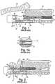
- the tissue apposition devicesmay be integrated with the endoscope shaft as shown in FIG. 5A , which presents a sectional view of the distal tip of the endoscope, through the working end of the apposition component.
- the integrated endoscope 51shown in FIG. 5A , comprises an endoscope shaft 53 and handle 89 having controls 57 for articulation of the endoscope distal tip 59. Also integrated into handle 89 at the proximal end 55 of the endoscope shaft may be controls for the operation of the accessory, including controls configured as shown in U.S. Pat. No. 5,910,105 .
- the tissue apposition device 61 located at the distal end 59 of the endoscopeis configured similarly to the device discussed in connection with FIGS. 1-3 above.
- the apposition portion 61comprises a vacuum chamber 63 into which aspirated tissue is collected in a plurality of suction ports 65 along the bottom of the vacuum chamber 63 for introduction of vacuum to selectively capture tissue into the chamber.
- the vacuum chamber 63may be formed from transparent polymer materials to improve visibility of the tissue as captured into the chamber and illumination provided by several light ports integrated into the endoscope. Shown in phantom in FIG. 5A is a needle pathway 67 along which the needle may be moved longitudinally through a captured tissue portion. Beneath the chamber, the endoscope continues distally and terminates at distal face 91.
- a removable cap 69which provides a chamber into which a suture carrying tag may be injected as discussed above in the operation of the prior art device of FIGS. 1-3 .
- FIG. 5Bis a sectional view of the integrated endoscope shaft 53 taken along the line 5B-5B in FIG. 5A .
- an exemplary arrangement of channels and endoscope componentsis shown.
- the several channels and components shown in FIG. 5Aeach extend the full length of the endoscope shaft 53 from the proximal end 55 where they may be accessed or controlled by the user, through to the distal end 59 of the shaft at the apposition portion 61.
- a biopsy channel 71is provided through which the needle end control wire to move the needle 67 may be inserted.
- the biopsy channelmay measure a diameter of approximately 2.79 millimeters (0.110 inches).
- Several light channels 75are provided through which optical fibers pass to transmit light from the proximal end 55 of the endoscope to the working apposition portion of the endoscope.
- a main objective lens 77 for viewingis provided and carries an optical fiber through the endoscope shaft to the proximal end 55 of the endoscope.
- a side viewing objective lens 79may be provided, also carrying an optical fiber through the endoscope shaft 53 to the proximal end 55.
- An internal vacuum line 81provides vacuum at the distal end 59 of the endoscope shaft from a vacuum connection at the proximal end 55.
- air and water ports 83 and 85may be provided through the shaft for providing cleaning means for the main viewing lens 77.
- Several articulation wires 87are also provided through the endoscope shaft 53 for the purpose of bending and curving the distal portion of the shaft as it is navigated to the treatment site. The articulation wires are anchored near the distal portion 59 of the endoscope shaft and extend proximally to the control knobs 57 on the handle 89 of the endoscope.
- the endoscope shaft 53may be made flexible, the distal working portion 59 comprising the apposition device 61 will be rigid to ensure smooth movement of the rigid needle 67 required for tissue penetration. Accordingly, the articulation of the endoscope shaft will be just proximal to the apposition portion. With the exemplary lumens and components described above, it is expected that the endoscope shaft will have an outside diameter on the order of 13.97 millimeters (0.550 inches). Finally, it is noted that the above-described example can be carried out in an apposition portion 61 having multiple vacuum chambers 63 as is shown in FIGS. 4A-D . Details of the operation and configuration of the multiple chamber apposition device may be found in US 2003/0208209 .
- FIG. 6shows another example of an integrated endoscope 100 having a tissue apposition device 102 at its distal end 104.
- the tissue apposition portion 102comprises a removable cylindrical cartridge 106 that is received over a reduced diameter core section 108 of the endoscope, shown in FIG. 7 .
- the cylindrical cartridgedefines a suction port 110 and vacuum chamber 112 into which a tissue portion may be collected under vacuum.
- the cartridgealso holds tissue capturing means that are delivered into the tissue along a circumferential path relative to the longitudinal axis of the endoscope.
- the cartridgemay be preloaded with the tissue capture means and may be made as a one-time use item that is disposable after use.
- the cartridgemay be secured to the endoscope by a screw 114 threaded into screw hole 116 on a distal face 118 of the endoscope prior to its reduction to the reduced diameter portion 108.
- a combination suction lumen and working channel 120is provided to carry elongated medical instruments.
- a telescoping and rotational objective lens 122is provided as well as a fixed objective lens 124 for providing viewing capability to the proximal end of the endoscope.
- a light guide 126may be provided at the center of the reduced diameter portion 108 to illuminate areas viewed through the objective lenses.
- An air and water port 128may be provided as a cleaning means for the objective lenses.
- a side suction port 130 on the side wall of the reduced diameter portion 108for communicating vacuum to the vacuum chamber 112 of the cylindrical cartridge.
- dual trigger mechanisms 134shown in phantom
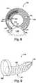
- FIG. 8The specific structure of the cylindrical cartridge 106 is shown in the sectional view presented in FIG. 8 , taken along the line 8-8 of FIG. 6 .
- a tissue portion 138is shown aspirated and collected into vacuum chamber 112 through suction port 110 of the cartridge.
- a single mound of tissue 138may be collected or two separate mounds collected if a partition is placed midway along the length of the suction port 110 to define two separate mounds of tissue.
- the cartridgecarries two sets of tissue apposition means comprising a plug 140 insertable through the tissue and engaging with a fastening ring 142 on the through side of the tissue.
- FIG. 9Details of the ring are shown in FIGS. 10A and 10B .
- the plugis pre-loaded and retained in a circumferential firing chamber 144 defined in the annular cross section of the cylindrical cartridge 106.
- the plugis curved to follow the arc shape of the firing chamber 144.
- the plughas a sharp piercing end 148 to penetrate tissue and a flat enlarged diameter cap portion 150 that is engaged by a firing spring 151 to drive the plug circumferentially through the captured tissue 138 and into the ring 142 frictionally held in a ring receptacle 152 formed in the cartridge 106.
- the enlarged flat head 150is offset from the center of the plug body to fully capture the driving force of firing spring 151 and to keep the plug 140 aligned within the firing chamber 144 as it is advanced.
- the firing spring 151is held in a compressed configuration by trigger 156 until delivery of the plug through a captured tissue portion as desired.
- the triggercan be pulled out of the way from the spring by a remote connection to the proximal end of the endoscope as will be explained below.
- the springWhen the spring is released, it expands along the circumferential pathway as defined by the firing chamber 144 and pushes the plug 140 through the tissue.
- the plug body 146becomes frictionally engaged in ring through hole 158.
- the ring through holeis not concentric with the outside diameter of the ring, but is located at one side of the ring to match the alignment of the offset plug body 146 relative to the plug head 150.
- the through hole 158is configured to taper gradually in diameter to a ridge 160 of reduced diameter in its center for the purpose of enhancing frictional engagement with the plug body 146.
- the plug body 146is made of a series of larger diameter ribs 162 that further enhance frictional engagement with the ring as they meet peaks of resistance as they align with the ridge 160 of the through hole 158 in the ring.
- the cartridge 106may be configured to hold two or more ring and plug assemblies spaced apart longitudinally by approximately one centimeter so that the tissue portion is secured simultaneously by two ring and plug assemblies. If a dividing wall is placed in the suction port 110, dividing it in half longitudinally, then two separate tissue mounds are formed and captured separately by the two ring and plug assemblies.
- the suction port 110may be divided by a partition wall extending longitudinally, as shown in FIGS. 11-14 .
- the cylindrical cartridge 106may be provided with a suction port 110 having a partition wall 164 extending longitudinally along its length.
- tissue portionis aspirated into the vacuum chamber 112, it is partitioned around the wall 164 to form two distinct mounds 138 as shown in FIGS. 11 and 13 .
- the partition wall 164extends across the suction port 110.
- the overhead view of the suction port 100 as shown in FIG. 12demonstrates that vacuum is introduced into the vacuum chamber through suction holes 111 spaced throughout the vacuum chamber 112.
- Firing chambers 144 located at the bottom of the suction chamberare arranged to aim the sharp piercing tip 148 of the pre-loaded plugs outward into tissue along a circular path so that they curve around through the two mounds of tissue segregated by the partition wall 164 and enter the rings 142 frictionally held in ring retainers 152 positioned on the opposite side of the vacuum chamber 112.
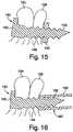
- FIGS. 14 and 15After the plugs 140 have been driven through the tissue and engaged with the rings 142 on the opposite side of the vacuum chamber, aspiration is discontinued and the tissue mounds 138 captured by the plug and ring 140 and 142 appear as shown in FIGS. 14 and 15 .
- the plug 140is inserted through both mounds of the partitioned tissue 138 and holds the tissue together in separate mounds with large cap 150 bearing on one side of the tissue and the ring 142 bearing on the other side of the tissue and locked onto the tip of the plug 140.
- FIG. 16is shown an alternate example of a ring 162.
- the ringperforms in the same manner as ring 142 but includes an extended cylindrical portion 164 that extends over the protruding sharp distal tip 148 of the plug so that adjacent tissue areas are not injured by the piercing tip.
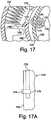
- FIG. 17shows a detailed drawing of the trigger 156 and trigger mechanism 134 that selectively releases the firing spring 151 to deliver the plug into the ring.
- the trigger 156comprises a spring engaging portion 166 that is slidably engaged with the inner side wall 168 of the cartridge 106.
- the spring engaging portionis pinned to a curved portion 170 of the trigger that extends through a trigger slot 172 and engages the trigger mechanism 134 that is slidably positioned on the exterior surface 132 of the reduced diameter portion 108 of the endoscope.
- the trigger mechanism 134extends through a slot 174 formed through the wall of reduced diameter portion 108 and forms an eyelet portion 176 that receives a trigger cable 178 that extends through the length of the endoscope shaft 53 to the handle 89 where it is joined to the working end of a trigger lever 180 that extends to the exterior of the handle for activation by the user as shown in FIG. 18 .
- the trigger cable 178is pulled proximally, which serves to slide trigger mechanisms 134 proximally as shown in the top view-- FIG. 17A ).
- FIG. 19is shown an alternate cylindrical cartridge apposition device.
- the modified endoscope 185has a reduced diameter portion 108 for receiving the cylindrical cartridge 106 as with the previous example discussed in connection with FIGS. 6 and 7 ; however, the endoscope further includes a viewing lens 124 and light source 184 on the large diameter end face 118 to provide additional viewing capability. Specifically, the additional viewing lens and light source will permit the operator to directly view tissue being suctioned into the vacuum chamber 112 of the cylindrical cartridge (not shown in FIG. 19 ).
- the vacuum chamber of the cylindrical cartridgemay have additional cutouts to eliminate walls that would otherwise obstruct the viewing capability of the lens 124.
- sealing gaskets 186are employed around the areas that will be overlayed by the vacuum chamber 112 when the cartridge is fitted over the reduced diameter portion 108 of the endoscope.
- the gasketswill help to ensure a sufficient vacuum is generated in the vacuum chamber to aspirate tissue completely before firing of the plug and ring tissue apposition elements.
- sensors 188may be placed adjacent to suction holes 111 on the side wall surface 132 of the reduced diameter portion 108 that signal when tissue has been fully aspirated into the vacuum chamber of the cartridge and send an electrical signal to the proximal end of the endoscope that can notify the user that sufficient aspiration has been obtained and firing of the tissue capture means can be commenced.
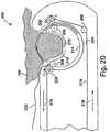
- FIG. 20shows a tissue apposition device according to an embodiment of the invention that may be embodied at the distal end of an integrated endoscope.
- the apposition device 200employs a semicircular needle 202 driven through a circular pathway 204 that is defined by two pairs of opposed pulleys 206 and 208.
- the circular pathway 204guides the needle through a vacuum chamber 210 which captures a tissue portion 138 by aspiration when vacuum is introduced through vacuum holes 212 at the bottom of the suction chamber.
- the needle 202travels through a circular pathway 204 defined by two sets of pulleys 206 and 208 and a circular needle track 214 that is formed at the distal end of the device 200 such that at least a portion of its arc travels through the vacuum chamber 210 so that the needle will pass through the tissue.
- Needle track 214is a circular passage of a diameter slightly greater than that of the needle to guide the needle as it is driven by pulleys.
- the sets of opposing pulleyseach comprise a driver pulley 206 and an idler pulley 208 that is opposed to the driver pulley.
- the driver pulleysare adjusted to move slightly into the needle track 214, closing the distance with the idler pulley so that the needle 202 becomes trapped therebetween.
- the driver pulleys 206are rotated, their engagement with the needle will cause the needle to move through the needle track 214 to complete a circular cycle.
- the driver pulleysmay be moved into an out of engagement by mechanical linkage controlled at the proximal end of the endoscope (not shown).
- the driver pulleys 206are driven by a driver cable 216 threaded around each pulley and around an idler pulley 208 and extending proximally through the endoscope to be driven by an external source.
- the needleWhen moved in the direction designated by arrows 218, the needle will be driven in a penetrating direction to deliver attached suture thread 220 through a tissue portion 138.
- vacuummay be discontinued to release the tissue portion and the distal tip of the endoscope moved to a new location, tissue aspirated and the needle again moved through its circular path to deliver the same suture lead.
- the devicemay be withdrawn carrying the threaded suture 220 proximally outside of the patient where knots may be applied or suture lock devices assembled onto the suture to secure it and complete the procedure.
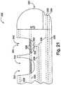
- FIG. 21shows another multiple suction port tissue apposition device shown in FIGS. 4A-4D .
- FIG. 21shows an integrated endoscope 222 having multiple suction chambers 224 into which tissue may be aspirated by introduction of vacuum through vacuum holes 226.
- the endoscopeis configured with additional viewing ports 232 and complementary adjacent cleaning ports 234.
- the viewing ports 232join to a lumen 236 containing an optical fiber extending through to the proximal end of the endoscope and through which viewing capability is obtained.
- the cleaning ports 234open to a lumen extending proximally to the proximal end of the endoscope that permit ejection of flushing liquid and air to clean the viewing port lens 232.
- the viewing and cleaning ports of the distal tip 240 of the deviceaid in navigating the endoscope to the intended tissue location by providing a viewing vantage point that is not obstructed by the structure of the apposition device.
- the viewing and cleaning ports 232 and 234 that terminate in the bottom of the vacuum chamber 242are useful in observing when the complete tissue mound has been aspirated into the chamber. When a tissue mound is fully collected, it contacts the face of the viewing port 232 causing a "red-out" condition that verifies for the operator that a complete tissue portion has been aspirated and it is safe to deliver the needle carrying a suture through the tissue mound.
- FIG. 22is a side partial sectional view of another integrated endoscope having a tissue apposition device 250 integrated at its distal end 252.
- the deviceutilizes an angulated tip presenting a distal face 254 that is angled away from the longitudinal axis of the endoscope by approximately 45.degree..
- a suction port 256is formed on the distal face for receiving tissue aspirated into the vacuum chamber 258.
- Along the back wall 260 of the vacuum chamberare located several conventional accessory ports found on the endoscopes of other examples described in the application.
- a vacuum port 262is provided that may be joined to two channels so that either vacuum or pressure for insuflation may be introduced through the same port and into the vacuum chamber 258.
- a viewing lens 264joined to an optical fiber and an air and water port 266 for cleaning the lens.
- a rigid needle 268is directed through a pathway that follows the longitudinal axis of the angulated distal face 54 in order to traverse the vacuum chamber 258 squarely so that captured tissue is accurately penetrated.
- the needle 268is advanced by the longitudinal movement of a flexible pusher 270 that is able to traverse the 45.degree. angle corner 272 within an appropriately formed sliding lumen and has sufficient column strength to drive the needle through tissue.
- the needlemay be hollow and deliver a permanent tag through its lumen to secure the tissue with suture as shown in FIGS. 4A and 4C of the prior art devices.
- FIG. 23shows another integrated endoscope comprising an apposition device 280 that drives a staple 282 through captured tissue.
- Multiple tissue moundsare aspirated into dual suction ports 284 separated by a split partition wall 286. Presence of partition wall causes the aspirated tissue to form into two separate mounds around the partition wall 286.
- a gap 288 in the partition wallis provided to allow the stapled tissue portions to be removed from the vacuum chamber 290 without having the staple become caught on the partition wall 286.
- a staple 282is advanced distally by pusher rod 292, which may be guided through a working channel of the endoscope.
- the pusher rodadvances distally to cause a staple to penetrate both mounds of tissue 138 and engage anvils 294 that cause the ends of the staple to buckle and collapse to secure the staple in the tissue as a conventional staple performs.
- the staple magazine 296may be provided to advance sequential staples in line with the pusher rod 292 as each preceding staple is ejected.
- the magazine 296may comprise a housing 298 with spring 299 keeping a constant force against the supply of staples so that they will eject from the housing automatically as each staple is ejected and the pusher rod 292 returns proximally past the magazine position so that a staple may be ejected into the pusher shaft pathway 297.
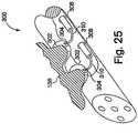
- FIG. 25shows another example of the integrated endoscope/accessory concept providing an apposition device 300 having multiple access ports 302 through which tissue can be grasped and manipulated.
- Tissuemay be grasped through the ports 302 by means such as forceps 304 as shown in FIG. 25 .
- the forceps 304may be advanced through working channels 308 and bend upward at articulation points 310 to extend through the access ports 302 to grasp tissue portions 138. As the forceps are withdrawn back through the access ports 302, the tissue mounds form as they engage the sides of the ports and are pulled in to the device.
- the tissue mounds 138may be injected with a bio absorbable bulking agent by a needle introduced through another channel of the endoscope.
- the tissue moundsmay be retained by placement of a ligating band on each tissue mound.
- the tissue moundsmay be grasped through the access ports by other means such as a barbed harpoon, a snare loop or rollers.
- FIG. 26shows a progression of steps in which a grasping device such as a forceps 304 is first navigated within the open chamber 313 at the distal end of the endoscope 312 and guided to a tissue location 315.
- a grasping devicesuch as a forceps 304 is first navigated within the open chamber 313 at the distal end of the endoscope 312 and guided to a tissue location 315.
- the forceps 304is advanced from the open chamber 313 and expanded to grasp a tissue portion. Once the tissue portion is grasped, the forceps are closed to pull it into the open chamber 313 of the endoscope 312 to define a tissue mound 138 that can then be manipulated with a tissue securing device.
Landscapes
- Health & Medical Sciences (AREA)
- Life Sciences & Earth Sciences (AREA)
- Surgery (AREA)
- General Health & Medical Sciences (AREA)
- Veterinary Medicine (AREA)
- Biomedical Technology (AREA)
- Heart & Thoracic Surgery (AREA)
- Medical Informatics (AREA)
- Molecular Biology (AREA)
- Animal Behavior & Ethology (AREA)
- Nuclear Medicine, Radiotherapy & Molecular Imaging (AREA)
- Public Health (AREA)
- Engineering & Computer Science (AREA)
- Physics & Mathematics (AREA)
- Biophysics (AREA)
- Optics & Photonics (AREA)
- Pathology (AREA)
- Radiology & Medical Imaging (AREA)
- Surgical Instruments (AREA)
- Endoscopes (AREA)
- Instruments For Viewing The Inside Of Hollow Bodies (AREA)
Description
- This invention relates to an integrated endoscope.
- Viewing endoscopes permit remote treatment of internal locations within a patient by accessing those locations through a natural body lumen avoiding the need for surgery in some cases. The advantages of using an endoscope to treat internal maladies of the human body has led to the development of various endoscopic accessory treatment devices that can be fastened to the distal end of the endoscope to carry out mechanical manipulation and treatment of internal tissue areas. Examples of such endoscopic accessories include suturing devices, cutting instruments, band ligating devices and forceps, among others. The accessories are securable to various types of endoscopes specifically designed for specific areas of the body and include: laparoscopes, duodenoscopes, colonoscopes, sigmoidoscopes, bronchoscopes, and urethroscopes, among others. In combination with remote viewing capability, endoscopes are frequently configured to provide a working channel through which controls for the scope mounted accessory may be inserted for remote operation.
- Although an endoscope carrying a treatment accessory provides remote treatment capability while permitting direct visualization of the treatment site, several shortcomings may arise in the use of the combination. First, the separate accessory may limit viewing capability through the distal end of the endoscope when it is attached so as to extend distally from the distal face of the endoscope. Second, there is always a risk that the accessory will become detached from the endoscope while in the patient, compromising the procedure and presenting problems for safely removing the detached accessory from the patient. Third, with various manufacturers producing endoscopes and accessories of differing diameters, mounting a particular accessory to an endoscope can be problematic if their diameters are not compatible. Fourth, the control mechanisms for operating the accessory must extend through existing working channels in the endoscope interfering with or prohibiting introduction of additional accessories or instruments through the endoscope during the procedure. Also, the accessory controls may be awkward to mount and operate in conjunction with the endoscope as the endoscope was not originally designed to accommodate such additional controls.
- It would be advantageous to provide an endoscope and operative treatment accessory that are designed to operate together to avoid the problems mentioned above encountered with separate devices. It is an object of the present invention to provide an integrated endoscope and treatment accessory in a single structure that overcomes the shortcomings of the prior art devices mentioned above.
- Document
US 2003/0208209 discloses an endoscopic tissue apposition device having multiple suction ports permit multiple folds of tissue to be captured in the suction ports with a single positioning of the device and attached together by a tissue securement mechanism such as a suture, staple or other form of tissue bonding. - It is known from
US5947983 to provide an endoscope comprising a shaft having proximal and distal ends, and a tissue apposition device at the distal end of the shaft, at least one apposition device control element extending the length of the shaft and an apposition control mechanism mounted at the proximal end of the shaft for controlling said tissue apposition device, the apposition device comprising at least one vacuum chamber that opens to the outside of the apposition device and which draws tissue by a vacuum introduced to the vacuum chamber, wherein the tissue apposition device comprises an arcuate needle configured for advancement within the apposition device through an arcuate path and means for driving the needle through the arcuate path, wherein tissue is drawn to said vacuum chamber to position the tissue along the arcuate path of the needle. - An integrated endoscope according to the present invention is characterized in that the circular path is located entirely in a single plane in an end to end direction of the device.
- The circular path of the semi-circular needle may pass through the vacuum chamber.
- The apposition device may comprise an circular track that coincides with the circular path travelled by the needle.
- The circular track may be formed at the distal end of the apposition device.
- The circular track may include two openings into the vacuum chamber.
- The integrated endoscope of the present invention may further comprise a suture thread attached to said semi-circular needle.
- The means for driving may be located along said circular path.
- The means for driving may comprise pulleys and the drive control element comprises a driver cable that extends around said pulleys.
- The pulleys may comprise a drive pulley and an idler pulley.
- The tissue apposition device may comprise a housing, said housing being integrated with the endoscope shaft.
- The vacuum chamber may be formed in the housing, the vacuum chamber including a suction port to suction tissue into the vacuum chamber.
- The foregoing and other objects and advantages of the invention will be appreciated more fully from the following further description thereof, with reference to
Figure 20 of the accompanying diagrammatic drawings wherein: FIGS. 1-3 show successive steps in the operation of a prior art single stitch sewing device;FIGS. 4A-4D are views of multiple suction port apposition devices in various stages of operation;FIG. 5A is a partial sectional side view of an integrated endoscope and treatment device accessory;FIG. 5B is a sectional view of the integrated endoscope ofFIG. 5A taken along theline 5B-5B;FIG. 6 is an isometric view of an integrated endoscope and medical device treatment accessory comprising a cylindrical cartridge assembled over the distal end of the endoscope;FIG. 7 is an isometric view of an integrated endoscope and medical device treatment accessory wherein the cylindrical cartridge has been removed from the distal end of the endoscope;FIG. 8 is a sectional view of the integrated endoscope shown inFIG. 6 taken along the line 8-8;FIG. 9 is a side view of the plug portion of a tissue apposition means device;FIGS. 10A and 10B are views of the ring portion of a tissue apposition means;FIG. 11 is a sectional view of an alternate cylindrical cartridge shown inFIG. 6 , taken along the line 8-8;FIG. 12 is a top view of the suction port of the cylindrical cartridge shown inFIG. 11 ;FIG. 13 is a diagrammatic illustration of two tissue portions after being aspirated into the suction port shown inFIG. 12 ;FIG. 14 is an illustration of tissue portions secured together by the apposition device shown inFIGS. 9-10B ;FIG. 15 is a side sectional view of tissue portions captured together by the tissue apposition device ofFIGS. 9-10B ;FIG. 16 is a side sectional view of tissue portions captured together by a modified version of the tissue apposition device shown inFIGS. 9-10B ;FIG. 17 is a detailed view of the trigger mechanism of the cylindrical cartridge shown inFIG. 6 ;FIG. 17A is a top view of a portion of the reduced diameter portion of the integrated endoscope shown inFIG. 7 ;FIG. 18 is a top view of an endoscope control handle employing a trigger lever;FIG. 19 is a variation of the cylindrical cartridge integrated endoscope employing a modified reduced diameter portion;FIG. 20 is a sectional side view of an embodiment of the integrated endoscope of the present invention having an accessory applying a semicircular needle for placing sutures through captured tissue portions;FIG. 21 is a side view of an integrated endoscope employing additional optics and optic cleaning ports;FIG. 22 is a side partial sectional view of an integrated endoscope employing an angulated distal face;FIG. 23 is a partial sectional side view of an integrated endoscope employing a tissue apposition accessory that deploys staples;FIG. 24 is a top view of an integrated endoscope employing a tissue apposition device that deploys staples;FIG. 25 is an isometric partial sectional view of an integrated endoscope and accessory employing multiple access ports;FIG. 26 is a series of three views of an integrated endoscope with a single access port and grasping device in various stages of operation.- The present invention provides an endoscope with an integrated tissue apposition device at its distal end. Several examples of an integrated endoscope employing tissue apposition devices are presented below. The examples of
Figures 1 to 19 and21 to 26 are described for the purposes of understanding the embodiment of the invention, which is described with reference toFigure 20 . FIGS. 1-3 depict a prior art endoscopic suturing device disclosed inU.S. Pat. No. 5,792,153 .FIG. 1 shows the distal end of aflexible endoscope 1, on which asewing device 2 is attached. The endoscope is provided with a viewing channel, which is not shown, but which terminates at a lens on the distal face of the endoscope. The endoscope is further provided with a biopsy or working channel 3, and asuction channel 4 the proximal end of which is connected to a source of vacuum (not shown). Thesuction channel 4 may comprise a separate tube that runs along the exterior of the endoscope, rather than an internal lumen as shown. Thesewing device 2 has atube 5, which communicates with thesuction pipe 4 and has a plurality ofperforations 6 therein. These perforations communicate with an upwardlyopen vacuum chamber 7 formed in the sewing device.- A
hollow needle 8 is mounted in the biopsy channel 3, with its beveled tip extending into the sewing device. The needle has a channel 9 extending therethrough. A flexible, wire-wound cable 10 has its forward end attached to the rear of theneedle 8, and acenter wire 11 runs within thecable 10, along the entire length thereof, and is longitudinally movable with respect thereto. The diameter of thewire 11 is such that it is longitudinally movable within the channel 9 and, in the position shown inFIG. 1 , the forward end portion of thewire 11 extends into the rear end portion of the channel 9. A thread carrier in the form of atag 12 is slidably and releasably mounted in the channel 9. The tag is shown in detail inFIG. 1A . The tag is hollow and has anaperture 13 extending through the sidewall thereof. As can also be seen inFIG. 1 , one end of athread 14 is secured to the tag by passing it through theaperture 13 and tying in the end of aknot 15 of sufficient size to prevent the thread escaping from the tag. The tag may be made from a relatively rigid material such as stainless steel. - At the distal end of the sewing device is defined a
hollow head portion 16 defining achamber 20 therein. Between thechamber 20 and thecavity 7 is awall 17, in which anaperture 18 is formed. Theaperture 18 has a diameter that is marginally greater than the external diameter of theneedle 8, and is aligned therewith. The clearance between theneedle 8 and theaperture 18 must be sufficiently small to prevent tissue being forced through the aperture and causing the needle to jam. Finally,FIG. 1 shows a portion of the patient'stissue 19, in which a stitch is to be formed. - In operation, suction is applied to the
suction pipe 4, and thence, via theperforations 6 in thetube 5 to thecavity 7. This sucks into the cavity aU-shaped portion 19a of thetissue 19, as shown inFIG. 2 . Thehollow needle 8 is pushed through theU-shaped tissue portion 19a by extending distally the wire-wound cable 10 and associatedneedle 8. After full advancement of the needle through both folds of the U-shaped tissue portion, the tip potion of theneedle 8 is distal to thewall 17 and within thechamber 20 in thehollow head portion 16. Distal movement ofwire 11, slidably received within thewound cable 10, pushes thetag 12 out of the channel 9 and into thechamber 20 where it rotates out of alignment withaperture 18 to become captured in the chamber. - The
wire 11 is then withdrawn proximally, followed by proximal withdrawal of thecable 10, to withdraw theneedle 8 from thetissue portion 19a. The suction is then discontinued allowing theU-shaped tissue portion 19a to be released from thecavity 7. As shown inFIG. 3 , the released tissue is left with asuture thread 14 passing through the two layers of tissue that form theU-shaped fold 19a. One end of the suture is joined to thetag 12 that remains captured in thechamber 20 and the other end of the suture extends through the patient's esophagus and out of the mouth. Finally, the endoscope and sewing device are withdrawn from the patient. In so doing, thethread 14 is pulled partially through thetissue portion 19a, as the capturedtag 12 is withdrawn proximally and brought outside the patient. With both ends of thethread 14 outside of the patient, the thread can be knotted and the knot endoscopically pushed down to the suture site and severed by an endoscopic knot pusher such as that disclosed inU.S. Pat. No. 6,010,515 (Swain et al ). - For certain treatments, capturing multiple tissue portions, gathering and holding them together may be desirable.
FIGS. 4A-4C illustrate the operation of a multiple suctionport apposition device 50 as disclosed in Patent Application PublicationUS 2003/0208209 . The device can capturemultiple tissue portions 52 simultaneously for application of a tissue securing device, such as a suture, tag or staple. The device may be modified to deliver the tissue securing devices of the present invention. Securing twotissue portions 52 in the same number of steps that the device ofUS5792153 requires to secure a single tissue portion doubles efficiency, reducing the total number of endoscopic intubations required to complete the procedure and reducing the time needed to complete the procedure. - The dual suction port tissue apposition device shown in
FIG. 4A passes through both tissue portions asuture 56 with atag 58 capturable in the end cap 60 of the sewing capsule 62, in similar fashion to the device discussed in connection withFIGS. 1-3 above. The dual suction port tissue apposition device shown inFIG. 4B passes through both tissue portions asuture 64 having apermanent tag 66 at its end. The permanent tag is not captured by the suturing device to later provide a lead for tying a surgical knot. Rather, the permanent tag remains in the body, anchored on the throughside 68 of the distal tissue portion. The tissue portions may then secured tightly together, not by a surgical knot, but by a frictionally engageable two piecesuture lock device 70 advanced along thesingle suture lead 64 to abut theproximal side 72 of the tissue portion. - In one example of the multiple suction port device, the multiple suction ports are defined in line on the sewing device, along a common longitudinal axis that is parallel to the longitudinal axis of the device. An isometric view of an in-line dual suction port endoscopic
tissue apposition device 50 is shown inFIGS. 4C . InFIG. 4C , a slotted and beveledhypodermic suturing needle 80 is in the fully retracted position, withsuture tag 58 not yet loaded, and the capsule ready to receive tissue. Thesewing device 50 is characterized by a tubular body orcapsule 74 that is machined from metal or injection molded from a rigid polymer material. The body may be formed with an atraumaticdistal tip 76 to avoid injury to the walls of a body lumen through which the device is delivered. - A plurality of
suction ports 86 are formed into the body along its length.Suction ports 86 are large openings defined through thecapsule 74, and open to one ormore vacuum chambers 82. The chambers are defined in the capsule bysurfaces forming sidewalls 84. Communication of the suction ports with thevacuum chambers 82 permits vacuum to reach tissue that is adjacent to the ports to accomplish capture oftissue portions 52 into the chamber. Any number of suction ports can be formed on the capsule body. However, two suction port devices are shown here as illustrative examples because often in the treatment of GERD, a series of two tissue mounds joined together are formed along the stomach wall, below the Z-line. Though more ports and chambers can be formed on the body, the extra body length they would require in the in-line example could potentially present difficulty during navigation of the rigid body through the curves of a natural body lumen. - Tissue portions are drawn into the suction ports and into the vacuum chambers by suction introduced to the chambers through
air passages 88. The air passages are open to independent internal channels in the body that are joined to vacuum lines 90. The vacuum lines extend from the proximal end of the capsule body, external to the endoscope, to the proximal end of the scope. Outside the patient, the vacuum lines can be joined to a portable or institutional vacuum source (not shown). A control valve may be inserted in-line near the proximal end of the tubes for selective control of the vacuum by the user. The air passages of all chambers may be joined and controlled by a single vacuum line. Alternatively, as shown inFIG. 4C , separate vacuum lines may be used to supply suction to the air passages of different vacuum chambers. Use of separate vacuum lines permits independent control of suction provided to the several chambers by the use of separate control valves for each vacuum tube at their proximal ends. - Independent vacuum supply to the air passages of each chamber not only helps to ensure adequate vacuum pressure to each chamber, but also permits sequential suctioning of tissue into the chambers. When tissue is collected into both chambers simultaneously, the distal chamber is blocked from the
viewing lens 48 on thedistal face 46 of theendoscope 1, as shown inFIG. 4B . Therefore, the physician is unable to visually determine whether tissue has been adequately collected into the vacuum chamber so that theneedle 80 can be safely advanced through. By applying vacuum first to the distal chamber, tissue collection into that chamber can be visually verified before the view is blocked by tissue entering the proximal chamber. Next, vacuum can be applied to the proximal chamber to capture tissue so that tissue is collected in both chambers simultaneously and held in readiness for penetration by the suture needle (or staple) through both tissue portions with one stroke. However, even with independent vacuum lines, it is possible, and may be desirable to apply a vacuum to all chambers simultaneously. - The
needle 80 is longitudinally slidable through thecapsule body 50, as in the prior art devices. In the in-line dual chamber shown inFIG. 4C , a tunnel-like needle track 92 extends longitudinally through solid portions in the upper half of the body, not otherwise defined by the vacuum chambers. From the needle track, athin suture channel 94 extends upwardly through the top surface of the capsule body to provide a space through which thesuture lead 64 may pass as thesuture tag 58 is advanced by the needle through theneedle track 92. Thechannel 94 is only a sufficient width to permit the suture to pass but is too small to permit passage of the larger needle orsuture tag 58. The small dimension of the channel helps maintain the needle and suture tag with in the needle track until they are extended distal to the most distal chamber. Anenlarged exit channel 96 extends upwardly from the needle track along the body a short distance distally from thedistal chamber 82. The enlarged channel facilitates exit of thesuture tag 58 from the body, to follow the released tissue to which it has been attached after being ejected from the extendedneedle 80 bypusher wire 98. Additionally, aramp 99 may be formed in the bottom surface of the needle track along the length of theexit channel 96. Extending upwardly as it extends distally, theramp 99 helps guide an ejected tag up and out from the exit channel and away from the capsule body. A detailed isometric view of the dual suction chamber device ofFIG. 4A in which thetag 58 is captured in thedistal end 76 of the device is shown inFIG. 4D . - The tissue apposition devices may be integrated with the endoscope shaft as shown in
FIG. 5A , which presents a sectional view of the distal tip of the endoscope, through the working end of the apposition component. Theintegrated endoscope 51, shown inFIG. 5A , comprises anendoscope shaft 53 and handle 89 havingcontrols 57 for articulation of the endoscopedistal tip 59. Also integrated intohandle 89 at theproximal end 55 of the endoscope shaft may be controls for the operation of the accessory, including controls configured as shown inU.S. Pat. No. 5,910,105 . - The
tissue apposition device 61 located at thedistal end 59 of the endoscope is configured similarly to the device discussed in connection withFIGS. 1-3 above. Theapposition portion 61 comprises avacuum chamber 63 into which aspirated tissue is collected in a plurality ofsuction ports 65 along the bottom of thevacuum chamber 63 for introduction of vacuum to selectively capture tissue into the chamber. Thevacuum chamber 63 may be formed from transparent polymer materials to improve visibility of the tissue as captured into the chamber and illumination provided by several light ports integrated into the endoscope. Shown in phantom inFIG. 5A is aneedle pathway 67 along which the needle may be moved longitudinally through a captured tissue portion. Beneath the chamber, the endoscope continues distally and terminates atdistal face 91. At the distal tip of the apposition portion is provided aremovable cap 69, which provides a chamber into which a suture carrying tag may be injected as discussed above in the operation of the prior art device ofFIGS. 1-3 . FIG. 5B is a sectional view of theintegrated endoscope shaft 53 taken along theline 5B-5B inFIG. 5A . In the sectional view, an exemplary arrangement of channels and endoscope components is shown. The several channels and components shown inFIG. 5A each extend the full length of theendoscope shaft 53 from theproximal end 55 where they may be accessed or controlled by the user, through to thedistal end 59 of the shaft at theapposition portion 61.- A
biopsy channel 71 is provided through which the needle end control wire to move theneedle 67 may be inserted. The biopsy channel may measure a diameter of approximately 2.79 millimeters (0.110 inches). Severallight channels 75 are provided through which optical fibers pass to transmit light from theproximal end 55 of the endoscope to the working apposition portion of the endoscope. One fiber terminating at theproximal wall 73 of thevacuum chamber 63. Two other light channels terminating atdistal face 91. A main objective lens 77 for viewing is provided and carries an optical fiber through the endoscope shaft to theproximal end 55 of the endoscope. Additionally, a side viewingobjective lens 79 may be provided, also carrying an optical fiber through theendoscope shaft 53 to theproximal end 55. Aninternal vacuum line 81 provides vacuum at thedistal end 59 of the endoscope shaft from a vacuum connection at theproximal end 55. Additionally, air andwater ports Several articulation wires 87 are also provided through theendoscope shaft 53 for the purpose of bending and curving the distal portion of the shaft as it is navigated to the treatment site. The articulation wires are anchored near thedistal portion 59 of the endoscope shaft and extend proximally to the control knobs 57 on thehandle 89 of the endoscope. It is noted that though theendoscope shaft 53 may be made flexible, the distal workingportion 59 comprising theapposition device 61 will be rigid to ensure smooth movement of therigid needle 67 required for tissue penetration. Accordingly, the articulation of the endoscope shaft will be just proximal to the apposition portion. With the exemplary lumens and components described above, it is expected that the endoscope shaft will have an outside diameter on the order of 13.97 millimeters (0.550 inches). Finally, it is noted that the above-described example can be carried out in anapposition portion 61 havingmultiple vacuum chambers 63 as is shown inFIGS. 4A-D . Details of the operation and configuration of the multiple chamber apposition device may be found inUS 2003/0208209 . FIG. 6 shows another example of anintegrated endoscope 100 having atissue apposition device 102 at itsdistal end 104. Thetissue apposition portion 102 comprises a removablecylindrical cartridge 106 that is received over a reduceddiameter core section 108 of the endoscope, shown inFIG. 7 . The cylindrical cartridge defines asuction port 110 andvacuum chamber 112 into which a tissue portion may be collected under vacuum. The cartridge also holds tissue capturing means that are delivered into the tissue along a circumferential path relative to the longitudinal axis of the endoscope. The cartridge may be preloaded with the tissue capture means and may be made as a one-time use item that is disposable after use. The cartridge may be secured to the endoscope by ascrew 114 threaded intoscrew hole 116 on adistal face 118 of the endoscope prior to its reduction to the reduceddiameter portion 108.- Through the reduced
diameter core portion 108 extend passages for conventional endoscope elements. A combination suction lumen and workingchannel 120 is provided to carry elongated medical instruments. A telescoping and rotationalobjective lens 122 is provided as well as a fixedobjective lens 124 for providing viewing capability to the proximal end of the endoscope. Alight guide 126 may be provided at the center of the reduceddiameter portion 108 to illuminate areas viewed through the objective lenses. An air andwater port 128 may be provided as a cleaning means for the objective lenses. Also provided is aside suction port 130 on the side wall of the reduceddiameter portion 108 for communicating vacuum to thevacuum chamber 112 of the cylindrical cartridge. Also provided on theside wall 132 of the reduceddiameter portion 108 are dual trigger mechanisms 134 (shown in phantom) that slide longitudinally to operate the tissue capture means release mechanism in the cylindrical cartridge. - The specific structure of the
cylindrical cartridge 106 is shown in the sectional view presented inFIG. 8 , taken along the line 8-8 ofFIG. 6 . InFIG. 8 , atissue portion 138 is shown aspirated and collected intovacuum chamber 112 throughsuction port 110 of the cartridge. A single mound oftissue 138 may be collected or two separate mounds collected if a partition is placed midway along the length of thesuction port 110 to define two separate mounds of tissue. The cartridge carries two sets of tissue apposition means comprising aplug 140 insertable through the tissue and engaging with afastening ring 142 on the through side of the tissue. A detail of the plug is shown inFIG. 9 . Details of the ring are shown inFIGS. 10A and 10B . - The plug is pre-loaded and retained in a
circumferential firing chamber 144 defined in the annular cross section of thecylindrical cartridge 106. The plug is curved to follow the arc shape of thefiring chamber 144. The plug has a sharp piercingend 148 to penetrate tissue and a flat enlargeddiameter cap portion 150 that is engaged by afiring spring 151 to drive the plug circumferentially through the capturedtissue 138 and into thering 142 frictionally held in aring receptacle 152 formed in thecartridge 106. Because theplug 140 travels along theoutside wall 144 of the firing chamber during its travel, the enlargedflat head 150 is offset from the center of the plug body to fully capture the driving force of firingspring 151 and to keep theplug 140 aligned within thefiring chamber 144 as it is advanced. - The
firing spring 151 is held in a compressed configuration bytrigger 156 until delivery of the plug through a captured tissue portion as desired. The trigger can be pulled out of the way from the spring by a remote connection to the proximal end of the endoscope as will be explained below. When the spring is released, it expands along the circumferential pathway as defined by thefiring chamber 144 and pushes theplug 140 through the tissue. As the plug is fired, theplug body 146 becomes frictionally engaged in ring throughhole 158. Shown best inFIGS. 10A and 10B , the ring through hole is not concentric with the outside diameter of the ring, but is located at one side of the ring to match the alignment of the offsetplug body 146 relative to theplug head 150. Additionally, the throughhole 158 is configured to taper gradually in diameter to aridge 160 of reduced diameter in its center for the purpose of enhancing frictional engagement with theplug body 146. - The
plug body 146 is made of a series oflarger diameter ribs 162 that further enhance frictional engagement with the ring as they meet peaks of resistance as they align with theridge 160 of the throughhole 158 in the ring. As mentioned above, thecartridge 106 may be configured to hold two or more ring and plug assemblies spaced apart longitudinally by approximately one centimeter so that the tissue portion is secured simultaneously by two ring and plug assemblies. If a dividing wall is placed in thesuction port 110, dividing it in half longitudinally, then two separate tissue mounds are formed and captured separately by the two ring and plug assemblies. - In an alternate arrangement, the
suction port 110 may be divided by a partition wall extending longitudinally, as shown inFIGS. 11-14 . As shown inFIGS. 11 and 12 , thecylindrical cartridge 106 may be provided with asuction port 110 having apartition wall 164 extending longitudinally along its length. When the tissue portion is aspirated into thevacuum chamber 112, it is partitioned around thewall 164 to form twodistinct mounds 138 as shown inFIGS. 11 and13 . - As shown in
FIG. 12 , thepartition wall 164 extends across thesuction port 110. The overhead view of thesuction port 100 as shown inFIG. 12 demonstrates that vacuum is introduced into the vacuum chamber throughsuction holes 111 spaced throughout thevacuum chamber 112. Firingchambers 144 located at the bottom of the suction chamber, are arranged to aim thesharp piercing tip 148 of the pre-loaded plugs outward into tissue along a circular path so that they curve around through the two mounds of tissue segregated by thepartition wall 164 and enter therings 142 frictionally held inring retainers 152 positioned on the opposite side of thevacuum chamber 112. - After the
plugs 140 have been driven through the tissue and engaged with therings 142 on the opposite side of the vacuum chamber, aspiration is discontinued and thetissue mounds 138 captured by the plug andring FIGS. 14 and15 . Theplug 140 is inserted through both mounds of thepartitioned tissue 138 and holds the tissue together in separate mounds withlarge cap 150 bearing on one side of the tissue and thering 142 bearing on the other side of the tissue and locked onto the tip of theplug 140. InFIG. 16 is shown an alternate example of aring 162. The ring performs in the same manner asring 142 but includes an extendedcylindrical portion 164 that extends over the protruding sharpdistal tip 148 of the plug so that adjacent tissue areas are not injured by the piercing tip. FIG. 17 shows a detailed drawing of thetrigger 156 andtrigger mechanism 134 that selectively releases thefiring spring 151 to deliver the plug into the ring. Thetrigger 156 comprises aspring engaging portion 166 that is slidably engaged with theinner side wall 168 of thecartridge 106. The spring engaging portion is pinned to acurved portion 170 of the trigger that extends through atrigger slot 172 and engages thetrigger mechanism 134 that is slidably positioned on theexterior surface 132 of the reduceddiameter portion 108 of the endoscope. Thetrigger mechanism 134 extends through aslot 174 formed through the wall of reduceddiameter portion 108 and forms aneyelet portion 176 that receives atrigger cable 178 that extends through the length of theendoscope shaft 53 to thehandle 89 where it is joined to the working end of atrigger lever 180 that extends to the exterior of the handle for activation by the user as shown inFIG. 18 . When the lever is operated as shown byarrow 182 inFIG. 18 , thetrigger cable 178 is pulled proximally, which serves to slidetrigger mechanisms 134 proximally as shown in the top view--FIG. 17A ). Movement of thetrigger mechanism 134 proximally pulls thecurved portion 170 andentire trigger 156 proximally such that thespring engaging portion 166 is pulled clear of thefiring spring 151, allowing it to release and fire the plug along its circumferential path in thefiring chamber 144.- In
FIG. 19 is shown an alternate cylindrical cartridge apposition device. The modified endoscope 185 has a reduceddiameter portion 108 for receiving thecylindrical cartridge 106 as with the previous example discussed in connection withFIGS. 6 and 7 ; however, the endoscope further includes aviewing lens 124 andlight source 184 on the largediameter end face 118 to provide additional viewing capability. Specifically, the additional viewing lens and light source will permit the operator to directly view tissue being suctioned into thevacuum chamber 112 of the cylindrical cartridge (not shown inFIG. 19 ). The vacuum chamber of the cylindrical cartridge may have additional cutouts to eliminate walls that would otherwise obstruct the viewing capability of thelens 124. Accordingly, sealinggaskets 186 are employed around the areas that will be overlayed by thevacuum chamber 112 when the cartridge is fitted over the reduceddiameter portion 108 of the endoscope. The gaskets will help to ensure a sufficient vacuum is generated in the vacuum chamber to aspirate tissue completely before firing of the plug and ring tissue apposition elements. - Additionally,
sensors 188 may be placed adjacent to suctionholes 111 on theside wall surface 132 of the reduceddiameter portion 108 that signal when tissue has been fully aspirated into the vacuum chamber of the cartridge and send an electrical signal to the proximal end of the endoscope that can notify the user that sufficient aspiration has been obtained and firing of the tissue capture means can be commenced. FIG. 20 shows a tissue apposition device according to an embodiment of the invention that may be embodied at the distal end of an integrated endoscope. Theapposition device 200 employs a semicircular needle 202 driven through acircular pathway 204 that is defined by two pairs of opposedpulleys circular pathway 204 guides the needle through avacuum chamber 210 which captures atissue portion 138 by aspiration when vacuum is introduced throughvacuum holes 212 at the bottom of the suction chamber.- As mentioned above, the needle 202 travels through a
circular pathway 204 defined by two sets ofpulleys circular needle track 214 that is formed at the distal end of thedevice 200 such that at least a portion of its arc travels through thevacuum chamber 210 so that the needle will pass through the tissue.Needle track 214 is a circular passage of a diameter slightly greater than that of the needle to guide the needle as it is driven by pulleys. The sets of opposing pulleys each comprise adriver pulley 206 and anidler pulley 208 that is opposed to the driver pulley. To drive the needle, the driver pulleys are adjusted to move slightly into theneedle track 214, closing the distance with the idler pulley so that the needle 202 becomes trapped therebetween. When the driver pulleys 206 are rotated, their engagement with the needle will cause the needle to move through theneedle track 214 to complete a circular cycle. The driver pulleys may be moved into an out of engagement by mechanical linkage controlled at the proximal end of the endoscope (not shown). - The driver pulleys 206 are driven by a
driver cable 216 threaded around each pulley and around anidler pulley 208 and extending proximally through the endoscope to be driven by an external source. When moved in the direction designated byarrows 218, the needle will be driven in a penetrating direction to deliver attachedsuture thread 220 through atissue portion 138. After the needle has been passed through thetissue portion 138, vacuum may be discontinued to release the tissue portion and the distal tip of the endoscope moved to a new location, tissue aspirated and the needle again moved through its circular path to deliver the same suture lead. After placing sutures through the desired number of tissue locations, the device may be withdrawn carrying the threadedsuture 220 proximally outside of the patient where knots may be applied or suture lock devices assembled onto the suture to secure it and complete the procedure. FIG. 21 shows another multiple suction port tissue apposition device shown inFIGS. 4A-4D . In particular,FIG. 21 shows anintegrated endoscope 222 havingmultiple suction chambers 224 into which tissue may be aspirated by introduction of vacuum through vacuum holes 226. In addition to the workingchannel lumen 228 andvacuum lumen 230, the endoscope is configured withadditional viewing ports 232 and complementaryadjacent cleaning ports 234. Theviewing ports 232 join to alumen 236 containing an optical fiber extending through to the proximal end of the endoscope and through which viewing capability is obtained. The cleaningports 234 open to a lumen extending proximally to the proximal end of the endoscope that permit ejection of flushing liquid and air to clean theviewing port lens 232.- The viewing and cleaning ports of the
distal tip 240 of the device aid in navigating the endoscope to the intended tissue location by providing a viewing vantage point that is not obstructed by the structure of the apposition device. The viewing and cleaningports vacuum chamber 242 are useful in observing when the complete tissue mound has been aspirated into the chamber. When a tissue mound is fully collected, it contacts the face of theviewing port 232 causing a "red-out" condition that verifies for the operator that a complete tissue portion has been aspirated and it is safe to deliver the needle carrying a suture through the tissue mound. FIG. 22 is a side partial sectional view of another integrated endoscope having atissue apposition device 250 integrated at itsdistal end 252. The device utilizes an angulated tip presenting a distal face 254 that is angled away from the longitudinal axis of the endoscope by approximately 45.degree.. A suction port 256 is formed on the distal face for receiving tissue aspirated into thevacuum chamber 258. Along theback wall 260 of the vacuum chamber are located several conventional accessory ports found on the endoscopes of other examples described in the application.- Specifically, a
vacuum port 262 is provided that may be joined to two channels so that either vacuum or pressure for insuflation may be introduced through the same port and into thevacuum chamber 258. Also on the back wall is aviewing lens 264 joined to an optical fiber and an air andwater port 266 for cleaning the lens. Arigid needle 268 is directed through a pathway that follows the longitudinal axis of the angulateddistal face 54 in order to traverse thevacuum chamber 258 squarely so that captured tissue is accurately penetrated. Theneedle 268 is advanced by the longitudinal movement of aflexible pusher 270 that is able to traverse the 45.degree.angle corner 272 within an appropriately formed sliding lumen and has sufficient column strength to drive the needle through tissue. The needle may be hollow and deliver a permanent tag through its lumen to secure the tissue with suture as shown inFIGS. 4A and4C of the prior art devices. FIG. 23 shows another integrated endoscope comprising anapposition device 280 that drives a staple 282 through captured tissue. Multiple tissue mounds are aspirated intodual suction ports 284 separated by asplit partition wall 286. Presence of partition wall causes the aspirated tissue to form into two separate mounds around thepartition wall 286. As shown inFIG. 24 , agap 288 in the partition wall is provided to allow the stapled tissue portions to be removed from thevacuum chamber 290 without having the staple become caught on thepartition wall 286.- In operation, after the tissue mounds are aspirated into the
vacuum chamber 290, astaple 282 is advanced distally bypusher rod 292, which may be guided through a working channel of the endoscope. The pusher rod advances distally to cause a staple to penetrate both mounds oftissue 138 and engageanvils 294 that cause the ends of the staple to buckle and collapse to secure the staple in the tissue as a conventional staple performs. - To permit the device to make multiple plications with one intubation, the
staple magazine 296 may be provided to advance sequential staples in line with thepusher rod 292 as each preceding staple is ejected. Themagazine 296 may comprise ahousing 298 withspring 299 keeping a constant force against the supply of staples so that they will eject from the housing automatically as each staple is ejected and thepusher rod 292 returns proximally past the magazine position so that a staple may be ejected into thepusher shaft pathway 297. FIG. 25 shows another example of the integrated endoscope/accessory concept providing anapposition device 300 havingmultiple access ports 302 through which tissue can be grasped and manipulated. Tissue may be grasped through theports 302 by means such asforceps 304 as shown inFIG. 25 . Theforceps 304 may be advanced through workingchannels 308 and bend upward at articulation points 310 to extend through theaccess ports 302 to grasptissue portions 138. As the forceps are withdrawn back through theaccess ports 302, the tissue mounds form as they engage the sides of the ports and are pulled in to the device.- Once grasped, the
tissue mounds 138 may be injected with a bio absorbable bulking agent by a needle introduced through another channel of the endoscope. Alternatively, the tissue mounds may be retained by placement of a ligating band on each tissue mound. The tissue mounds may be grasped through the access ports by other means such as a barbed harpoon, a snare loop or rollers. - As shown in
FIG. 26 , the grasping mechanisms may be employed through an open distal end of anendoscope 312 providing asingle access port 314.FIG. 26 shows a progression of steps in which a grasping device such as aforceps 304 is first navigated within theopen chamber 313 at the distal end of theendoscope 312 and guided to atissue location 315. When the desired tissue location is reached, theforceps 304 is advanced from theopen chamber 313 and expanded to grasp a tissue portion. Once the tissue portion is grasped, the forceps are closed to pull it into theopen chamber 313 of theendoscope 312 to define atissue mound 138 that can then be manipulated with a tissue securing device.
Claims (12)
- An integrated endoscope comprising a shaft having proximal and distal ends, and a tissue apposition device (200) at the distal end of the shaft, at least one apposition device control element extending the length of the shaft and an apposition control mechanism mounted at the proximal end of the shaft for controlling said tissue apposition device (200), the apposition device (200) comprising at least one vacuum chamber (210) that opens to the outside of the apposition device (200) and which draws tissue by a vacuum introduced to the vacuum chamber (210), wherein the tissue apposition device (200) comprises semicircular needle (202) configured for advancement within the apposition device (200) through an circular path (204) and means for driving the needle (202) through the circular path (204), wherein tissue is drawn to said vacuum chamber (210) to position the tissue along the circular path (204) of the needle (202), wherein the circular path (204) is located entirely in a single plane in an end to end direction of the device.
- An integrated endoscope according to claim 1, wherein said circular path (204) of said needle (202) passes through said vacuum chamber (210).
- An integrated endoscope according to claim 2, wherein the apposition device (200) comprises a circular track (214) that coincides with the circular path (204) travelled by said needle (202).
- An integrated endoscope according to claim 3, wherein the circular track (214) is formed at the distal end of the apposition device (200).
- An integrated endoscope according to claims 3 or 4, wherein the circular track (214) includes two openings into the vacuum chamber (210).
- An integrated endoscope according to any preceding claim, comprising a suture thread (220) attached to said semi-circular needle (202).
- An integrated endoscope according to any preceding claim, wherein said means for driving is located along said circular path (204).
- An integrated endoscope according to claim 7, wherein the means for driving comprises pulleys (206, 208) and the drive control element comprises a driver cable (216) that extends around said pulleys (206,208).
- An integrated endoscope according to claim 8, wherein the pulleys (206, 208) comprise a drive pulley (206) and an idler pulley (208).
- An integrated endoscope according to any preceding claim, wherein the tissue apposition device (200) comprises a housing, said housing being integrated with the endoscope shaft.
- An integrated endoscope according to claim 10, wherein the vacuum chamber (210) is formed in the housing, the vacuum chamber (210) including a suction port to suction tissue into the vacuum chamber (210).
- An integrated endoscope according to claim 11, wherein the suction port is in a sidewall of said housing.
Applications Claiming Priority (3)
| Application Number | Priority Date | Filing Date | Title |
|---|---|---|---|
| US40855602P | 2002-09-06 | 2002-09-06 | |
| US408556P | 2002-09-06 | ||
| PCT/US2003/028118WO2004021873A2 (en) | 2002-09-06 | 2003-09-08 | Integrated endoscope and accessory treatment device |
Publications (3)
| Publication Number | Publication Date |
|---|---|
| EP1538965A2 EP1538965A2 (en) | 2005-06-15 |
| EP1538965A4 EP1538965A4 (en) | 2008-04-09 |
| EP1538965B1true EP1538965B1 (en) | 2018-10-17 |
Family
ID=31978628
Family Applications (1)
| Application Number | Title | Priority Date | Filing Date |
|---|---|---|---|
| EP03754465.7AExpired - LifetimeEP1538965B1 (en) | 2002-09-06 | 2003-09-08 | Integrated endoscope and accessory treatment device |
Country Status (6)
| Country | Link |
|---|---|
| US (3) | US20040158125A1 (en) |
| EP (1) | EP1538965B1 (en) |
| JP (2) | JP2006512108A (en) |
| AU (1) | AU2003272289A1 (en) |
| ES (1) | ES2702605T3 (en) |
| WO (1) | WO2004021873A2 (en) |
Families Citing this family (99)
| Publication number | Priority date | Publication date | Assignee | Title |
|---|---|---|---|---|
| WO2000059376A1 (en)* | 1999-04-07 | 2000-10-12 | Endonetics, Inc. | Implantable monitoring probe |
| US6663639B1 (en) | 1999-06-22 | 2003-12-16 | Ndo Surgical, Inc. | Methods and devices for tissue reconfiguration |
| US6821285B2 (en) | 1999-06-22 | 2004-11-23 | Ndo Surgical, Inc. | Tissue reconfiguration |
| US7618426B2 (en) | 2002-12-11 | 2009-11-17 | Usgi Medical, Inc. | Apparatus and methods for forming gastrointestinal tissue approximations |
| US7416554B2 (en) | 2002-12-11 | 2008-08-26 | Usgi Medical Inc | Apparatus and methods for forming and securing gastrointestinal tissue folds |
| US7744613B2 (en) | 1999-06-25 | 2010-06-29 | Usgi Medical, Inc. | Apparatus and methods for forming and securing gastrointestinal tissue folds |
| US7993368B2 (en) | 2003-03-13 | 2011-08-09 | C.R. Bard, Inc. | Suture clips, delivery devices and methods |
| EP1261282B1 (en) | 2000-03-03 | 2013-09-25 | C. R. Bard, Inc. | Endoscopic tissue apposition device with multiple suction ports |
| US8105351B2 (en)* | 2001-05-18 | 2012-01-31 | C.R. Bard, Inc. | Method of promoting tissue adhesion |
| ES2435094T3 (en) | 2000-05-19 | 2013-12-18 | C.R. Bard, Inc. | Device and method of tissue capture and suturing |
| WO2004021873A2 (en) | 2002-09-06 | 2004-03-18 | C.R. Bard, Inc. | Integrated endoscope and accessory treatment device |
| US7942884B2 (en) | 2002-12-11 | 2011-05-17 | Usgi Medical, Inc. | Methods for reduction of a gastric lumen |
| US7942898B2 (en) | 2002-12-11 | 2011-05-17 | Usgi Medical, Inc. | Delivery systems and methods for gastric reduction |
| CN1822794B (en) | 2003-05-16 | 2010-05-26 | C.R.巴德有限公司 | Single cannula, multiple needle endoscopic suturing system |
| US8216252B2 (en) | 2004-05-07 | 2012-07-10 | Usgi Medical, Inc. | Tissue manipulation and securement system |
| US7361180B2 (en) | 2004-05-07 | 2008-04-22 | Usgi Medical, Inc. | Apparatus for manipulating and securing tissue |
| US20050251189A1 (en) | 2004-05-07 | 2005-11-10 | Usgi Medical Inc. | Multi-position tissue manipulation assembly |
| US7347863B2 (en) | 2004-05-07 | 2008-03-25 | Usgi Medical, Inc. | Apparatus and methods for manipulating and securing tissue |
| US7703459B2 (en) | 2004-03-09 | 2010-04-27 | Usgi Medical, Inc. | Apparatus and methods for mapping out endoluminal gastrointestinal surgery |
| US7918869B2 (en) | 2004-05-07 | 2011-04-05 | Usgi Medical, Inc. | Methods and apparatus for performing endoluminal gastroplasty |
| US7736374B2 (en) | 2004-05-07 | 2010-06-15 | Usgi Medical, Inc. | Tissue manipulation and securement system |
| US8257394B2 (en) | 2004-05-07 | 2012-09-04 | Usgi Medical, Inc. | Apparatus and methods for positioning and securing anchors |
| US7520884B2 (en) | 2004-05-07 | 2009-04-21 | Usgi Medical Inc. | Methods for performing gastroplasty |
| US7931661B2 (en) | 2004-06-14 | 2011-04-26 | Usgi Medical, Inc. | Apparatus and methods for performing transluminal gastrointestinal procedures |
| US7780592B2 (en)* | 2004-10-29 | 2010-08-24 | Medtronic, Inc. | Distal portion of an endoscopic delivery system |
| US7846169B2 (en)* | 2005-06-13 | 2010-12-07 | Ethicon Endo-Surgery, Inc. | Adjustable vacuum chamber for a surgical suturing apparatus |
| US8906040B2 (en)* | 2005-07-13 | 2014-12-09 | Creighton University | Systems and techniques for minimally invasive gastrointestinal procedures |
| US8641729B2 (en) | 2005-07-13 | 2014-02-04 | Creighton University | Systems and techniques for minimally invasive gastrointestinal procedures |
| US8216158B2 (en)* | 2005-07-20 | 2012-07-10 | Medtronic, Inc. | Implantation of a medical device within a lumen |
| US7896894B2 (en)* | 2005-08-05 | 2011-03-01 | Ethicon Endo-Surgery, Inc. | Apparatus for single pass gastric restriction |
| US7896890B2 (en)* | 2005-09-02 | 2011-03-01 | Ethicon Endo-Surgery, Inc. | Method and apparatus for endoscopically performing gastric reduction surgery in a single step |
| US8726909B2 (en) | 2006-01-27 | 2014-05-20 | Usgi Medical, Inc. | Methods and apparatus for revision of obesity procedures |
| US20070239206A1 (en)* | 2006-03-31 | 2007-10-11 | Shelton Frederick E Iv | Suture with adhesive/sealant delivery mechanism |
| US9005220B2 (en) | 2006-04-04 | 2015-04-14 | C.R. Bard, Inc. | Suturing devices and methods with energy emitting elements |
| US7731727B2 (en)* | 2006-04-26 | 2010-06-08 | Lsi Solutions, Inc. | Medical instrument to place a pursestring suture, open a hole and pass a guidewire |
| US8038598B2 (en)* | 2006-05-15 | 2011-10-18 | Baystate Health, Inc. | Balloon endoscope device |
| US7927271B2 (en)* | 2006-05-17 | 2011-04-19 | C.R. Bard, Inc. | Endoscope tool coupling |
| US20070276409A1 (en)* | 2006-05-25 | 2007-11-29 | Ethicon Endo-Surgery, Inc. | Endoscopic gastric restriction methods and devices |
| US8870916B2 (en) | 2006-07-07 | 2014-10-28 | USGI Medical, Inc | Low profile tissue anchors, tissue anchor systems, and methods for their delivery and use |
| CN101511294B (en)* | 2006-08-30 | 2013-09-18 | 学校法人自治医科大学 | Treatment instrument for endoscope |
| WO2008043044A2 (en)* | 2006-10-04 | 2008-04-10 | Ndo Surgical, Inc. | Devices and methods for endoluminal gastric restriction tissue manipulation, and drug delivery |
| US8038868B2 (en)* | 2006-10-04 | 2011-10-18 | Thermo Orion, Inc. | Micro PH electrode (reference electrode) |
| US9675285B2 (en)* | 2006-10-16 | 2017-06-13 | Given Imaging Ltd. | Delivery device for implantable monitor |
| US8852216B2 (en) | 2007-03-23 | 2014-10-07 | Ethicon Endo-Surgery, Inc. | Tissue approximation methods |
| CN102112163A (en)* | 2008-07-28 | 2011-06-29 | 脊柱诊察公司 | Penetrating member with direct visualization |
| US8863748B2 (en)* | 2008-07-31 | 2014-10-21 | Olympus Medical Systems Corp. | Endoscopic surgical operation method |
| EP2341841B1 (en) | 2008-09-29 | 2019-12-04 | C.R.Bard, Inc. | Endoscopic suturing device |
| US8376932B2 (en)* | 2008-10-29 | 2013-02-19 | Cook Medical Technologies Llc | Endoscope endcap for suturing tissue |
| WO2010055796A1 (en)* | 2008-11-13 | 2010-05-20 | オリンパスメディカルシステムズ株式会社 | Capsule-type medical device |
| US20130066304A1 (en) | 2009-02-27 | 2013-03-14 | Modular Surgical, Inc. | Apparatus and methods for hybrid endoscopic and laparoscopic surgery |
| US8562632B2 (en)* | 2009-09-18 | 2013-10-22 | Edwards Lifesciences Corporation | Shafted surgical instrument for remote access surgical procedures |
| US8219171B2 (en)* | 2010-03-16 | 2012-07-10 | Given Imaging Ltd. | Delivery device for implantable monitor |
| US20130023904A1 (en)* | 2011-07-20 | 2013-01-24 | Yoshinori Morita | Suturing method |
| JP6197158B2 (en)* | 2012-03-09 | 2017-09-20 | 敦子 大熊 | Endoscopic suture device |
| US20150051450A1 (en)* | 2012-03-30 | 2015-02-19 | The Regents Of The University Of California | System, device and method for measurement of esophageal wall blood perfusion |
| EP2838435B1 (en)* | 2012-04-16 | 2020-03-25 | Hathaway, Jeff M. | Biopsy device |
| US9398905B2 (en) | 2012-12-13 | 2016-07-26 | Ethicon Endo-Surgery, Llc | Circular needle applier with offset needle and carrier tracks |
| US9125645B1 (en) | 2013-03-11 | 2015-09-08 | Ethicon Endo-Surgery, Inc. | Reciprocating needle drive without cables |
| USD771811S1 (en) | 2013-03-15 | 2016-11-15 | Ethicon Endo-Surgery, Llc | Suture tray |
| US9375212B2 (en) | 2014-06-06 | 2016-06-28 | Ethicon Endo-Surgery, Llc | Circular needle applier with cleats |
| US20150351749A1 (en) | 2014-06-06 | 2015-12-10 | Ethicon Endo-Surgery, Inc. | Needle Cartridge with Moveable Cover |
| WO2014201563A1 (en)* | 2013-06-18 | 2014-12-24 | The Hospital For Sick Children | Tissue gripping device |
| EP3054860B1 (en) | 2013-10-10 | 2020-07-01 | Nitinotes Ltd. | Endoluminal sleeve gastroplasty |
| US10779979B2 (en) | 2013-10-10 | 2020-09-22 | Nitinotes Ltd. | Endoluminal sleeve gastroplasty |
| US10166030B2 (en) | 2014-02-03 | 2019-01-01 | Modular Surgical, Inc. | Surgical tool system having multiple tool tip interfaces |
| US10004490B2 (en) | 2014-06-06 | 2018-06-26 | Ethicon Llc | Force limited needle driver |
| USD745146S1 (en) | 2014-06-06 | 2015-12-08 | Ethicon Endo-Surgery, Inc. | Surgical suturing device |
| US9993243B2 (en) | 2014-09-09 | 2018-06-12 | Edwards Lifesciences Corporation | Finger-mounted surgical instruments and methods of use |
| EP3203918B1 (en)* | 2014-10-08 | 2023-09-20 | Nitinotes Ltd. | Endoluminal sleeve gastroplasty |
| US10022120B2 (en) | 2015-05-26 | 2018-07-17 | Ethicon Llc | Surgical needle with recessed features |
| US9883858B1 (en)* | 2015-06-15 | 2018-02-06 | Ethicon Endo-Surgery, Llc | Suturing instrument with robotic drive interface |
| USD800306S1 (en) | 2015-12-10 | 2017-10-17 | Ethicon Llc | Surgical suturing device |
| US11141147B2 (en)* | 2016-08-10 | 2021-10-12 | Apollo Endosurgery Us, Inc. | Endoscopic suturing system having external instrument channel |
| US10660644B2 (en)* | 2016-10-14 | 2020-05-26 | Logan Medical Devices, Inc. | Rectal band ligation device and method of operation thereof |
| USD865964S1 (en) | 2017-01-05 | 2019-11-05 | Ethicon Llc | Handle for electrosurgical instrument |
| US10751044B2 (en) | 2017-02-02 | 2020-08-25 | Covidien Lp | Vaginal tissue closure |
| US10898181B2 (en) | 2017-03-17 | 2021-01-26 | Cypris Medical, Inc. | Suturing system |
| US10660637B2 (en)* | 2018-04-06 | 2020-05-26 | Cypris Medical, Inc. | Suturing system |
| JP7279092B2 (en)* | 2018-04-06 | 2023-05-22 | サイプリス メディカル, インコーポレイテッド | suture system |
| US11033261B2 (en) | 2018-05-31 | 2021-06-15 | Cypris Medical, Inc. | Suture system |
| US11298122B2 (en)* | 2018-06-07 | 2022-04-12 | EnVision Endoscopy, Inc. | Endoscopic suturing device with circular needle |
| JP7320523B2 (en)* | 2018-10-24 | 2023-08-03 | 株式会社カネカ | Bi-directional medical suture system |
| USD895112S1 (en) | 2018-11-15 | 2020-09-01 | Ethicon Llc | Laparoscopic bipolar electrosurgical device |
| US20210093163A1 (en)* | 2019-09-26 | 2021-04-01 | Boston Scientific Scimed, Inc. | Endoscope with integrated tissue acquisition capability |
| WO2020144693A1 (en)* | 2019-01-09 | 2020-07-16 | Nitinotes Ltd. | Tissue manipulation with an endoluminal gastroplasty device |
| EP3941397B1 (en)* | 2019-03-19 | 2025-09-03 | Coremedic GmbH | Instrument for repairing an atrioventricular heart valve |
| US20220257236A9 (en)* | 2019-06-06 | 2022-08-18 | EnVision Endoscopy, Inc. | Endoscopic suturing device |
| WO2021046089A1 (en)* | 2019-09-06 | 2021-03-11 | Boston Scientific Scimed, Inc. | Devices and methods for suturing tissue |
| US11547286B2 (en)* | 2020-01-22 | 2023-01-10 | Brio13Inv. LLC | Stylet assembly |
| WO2021171290A1 (en) | 2020-02-26 | 2021-09-02 | Nitinotes Ltd. | Suturing with an endoluminal gastroplasty device |
| CA3173298A1 (en)* | 2020-02-27 | 2021-09-02 | Altyx Surgical Inc. | Tissue surface piercing systems and methods |
| CN111436979B (en)* | 2020-04-07 | 2021-06-15 | 温州医科大学附属第二医院、温州医科大学附属育英儿童医院 | A kind of rotary shifting device and handle convenient for operation under endoscope |
| US12137899B2 (en) | 2020-05-11 | 2024-11-12 | Cypris Medical, Inc. | Multiple suture placement system |
| EP3973854A1 (en)* | 2020-09-29 | 2022-03-30 | Koninklijke Philips N.V. | An optical spectroscopy system |
| EP4231947A4 (en) | 2020-10-23 | 2024-10-02 | Envision Endoscopy, Inc. | ENDOSCOPIC SUTURE STRAP |
| US12011161B2 (en)* | 2021-01-21 | 2024-06-18 | Ethicon, Inc. | Suture needle adaptors for delivering suture needles through cannulas while simultaneously visualizing the delivery of the suture needles through the cannulas |
| US11701107B2 (en)* | 2021-03-26 | 2023-07-18 | Tsymm Innovations Llc | Suturing device and clamp for use with same |
| CN119074091B (en)* | 2024-09-20 | 2025-10-03 | 重庆西山科技股份有限公司 | Suture device |
| CN119367667B (en)* | 2024-12-31 | 2025-05-06 | 温州医科大学附属第一医院 | Mechanical decompression type drug delivery and minimally invasive surgical operation device for colorectal anus |
Family Cites Families (352)
| Publication number | Priority date | Publication date | Assignee | Title |
|---|---|---|---|---|
| US1325699A (en) | 1919-12-23 | John h | ||
| US453508A (en)* | 1891-06-02 | Veterinary instrument | ||
| US469101A (en)* | 1892-02-16 | Water-heater | ||
| US730152A (en)* | 1902-12-06 | 1903-06-02 | Marion W Pitner | Fabric-turfing machine. |
| US979342A (en) | 1908-03-11 | 1910-12-20 | Charles B A Schaefer | Collar-fastener. |
| US1868308A (en)* | 1930-02-01 | 1932-07-19 | Ross E Brumfield | Capsule gun |
| US2170599A (en)* | 1937-07-20 | 1939-08-22 | Elza A Stricklen | Veterinary dose gun |
| US2587364A (en)* | 1948-05-20 | 1952-02-26 | Edith Mitchell | Balling gun |
| US2601852A (en)* | 1950-05-19 | 1952-07-01 | Delbert O Wendt | Device for dispensing tablets and the like |
| US2650593A (en)* | 1951-08-22 | 1953-09-01 | Jay D Weil | Balling gun |
| US2621655A (en) | 1951-10-11 | 1952-12-16 | Kenneth L Gothard | Tablet dispensing gun |
| US2880728A (en)* | 1958-02-03 | 1959-04-07 | Clyde S Rights | Ligature inserter |
| US3013559A (en) | 1959-05-06 | 1961-12-19 | Wesley C Thomas | Instrument for closing flesh wounds |
| US3168097A (en)* | 1960-08-02 | 1965-02-02 | Porges | Needle holder having a rotating clamp for surgical sutures |
| US3238941A (en)* | 1963-06-19 | 1966-03-08 | Frost Eng Dev | Balling gun |
| US3470875A (en)* | 1966-10-06 | 1969-10-07 | Alfred A Johnson | Surgical clamping and suturing instrument |
| US3716058A (en)* | 1970-07-17 | 1973-02-13 | Atlanta Res Inst | Barbed suture |
| DE2157911C2 (en)* | 1970-12-11 | 1982-02-04 | Marc Edmond Jean van Bruxelles Hoorn | Surgical device for ligating internal structures |
| US3757781A (en)* | 1971-09-17 | 1973-09-11 | R Smart | Tool for administering pills to animals |
| US3858571A (en)* | 1973-07-02 | 1975-01-07 | Arthur I Rudolph | Cornual plug |
| US3845772A (en) | 1973-09-17 | 1974-11-05 | D Smith | Retention suture device and method |
| US4126124A (en) | 1975-12-05 | 1978-11-21 | Hairegenics, Inc. | Method of sizing a hair anchor |
| US4216777A (en)* | 1977-07-01 | 1980-08-12 | Pridemore William J | Method for artificially implanting hair |
| DE2734441C2 (en) | 1977-07-30 | 1979-09-06 | Gebhard 7710 Donaueschingen Dischinger | Hand tool for threading strings |
| US4144876A (en)* | 1977-12-20 | 1979-03-20 | Deleo David B | Hair implanting method |
| US4164225A (en)* | 1977-12-28 | 1979-08-14 | Johnson & Lorenz, Inc. | Surgical suturing instrument |
| US4226239A (en)* | 1978-01-31 | 1980-10-07 | Kli, Inc. | Surgical ligating instrument and method |
| US4210148A (en)* | 1978-11-03 | 1980-07-01 | Stivala Oscar G | Retention suture system |
| IT1100419B (en)* | 1978-11-29 | 1985-09-28 | Castoldi Spa | SUCTION DEVICE FOR REACTION GROUPS FOR BOAT AND GROUPS THAT INCLUDE IT |
| DE2853289C2 (en)* | 1978-12-09 | 1980-12-18 | B. Braun Melsungen Ag, 3508 Melsungen | Button for surgical use |
| US4236470A (en) | 1979-01-17 | 1980-12-02 | Stenson Thomas K | Portable stitching device |
| DE3045295A1 (en)* | 1979-05-21 | 1982-02-18 | American Cystoscope Makers Inc | Surgical instrument for an endoscope |
| JPS55166142A (en)* | 1979-06-14 | 1980-12-25 | Olympus Optical Co | Capsule device for medical treatment |
| US4414908A (en) | 1979-12-04 | 1983-11-15 | Janome Sewing Machine Co. Ltd. | Suturing machine for medical treatment |
| US4345601A (en)* | 1980-04-07 | 1982-08-24 | Mamoru Fukuda | Continuous suturing device |
| US4469101A (en) | 1980-10-23 | 1984-09-04 | Battelle Memorial Institute | Suture device |
| JPS57170239A (en)* | 1981-04-13 | 1982-10-20 | Janome Sewing Machine Co Ltd | Holding of shuttle of suturing device for operation |
| USD279504S (en) | 1981-05-15 | 1985-07-02 | Ortho Pharmaceutical Corporation | Vaginal applicator |
| US4415092A (en) | 1981-06-01 | 1983-11-15 | Boyer Thomas B | Holder for uniformly shaped articles |
| US4493319A (en)* | 1981-06-29 | 1985-01-15 | Cabot Medical Corporation | Ring applicator having floating inner tube |
| US4860746A (en)* | 1982-04-20 | 1989-08-29 | Inbae Yoon | Elastic surgical ring clip and ring loader |
| US5417691A (en) | 1982-05-20 | 1995-05-23 | Hayhurst; John O. | Apparatus and method for manipulating and anchoring tissue |
| US4741330A (en)* | 1983-05-19 | 1988-05-03 | Hayhurst John O | Method and apparatus for anchoring and manipulating cartilage |
| EP0117894B1 (en)* | 1983-02-08 | 1989-11-08 | Storz-Endoskop GmbH | Endoscope comprising a medical gripping instrument |
| SE441643B (en)* | 1983-02-08 | 1985-10-28 | Innova Ab | suturing instrument |
| GB8311345D0 (en)* | 1983-04-26 | 1983-06-02 | Dobson Park Ind | Oral administration of capsules to animals |
| US5125553A (en)* | 1987-03-02 | 1992-06-30 | Stryker Sales Corporation | Surgical suturing instrument and method |
| US5220928A (en)* | 1983-08-22 | 1993-06-22 | Stryker Sales Corporation | Surgical procedure for joining tissue in an internal body cavity |
| US4665906A (en)* | 1983-10-14 | 1987-05-19 | Raychem Corporation | Medical devices incorporating sim alloy elements |
| US4621640A (en) | 1984-01-09 | 1986-11-11 | Mulhollan James S | Mechanical needle carrier and method for its use |
| US4597390A (en)* | 1984-04-02 | 1986-07-01 | Mulhollan James S | Surgical needle manipulator |
| GB8422863D0 (en)* | 1984-09-11 | 1984-10-17 | Univ London | Sewing machine |
| US4721103A (en)* | 1985-01-31 | 1988-01-26 | Yosef Freedland | Orthopedic device |
| US4615472A (en)* | 1985-06-19 | 1986-10-07 | Intravascular Surgical Instruments, Inc. | Catheter placement device |
| JPH0434499Y2 (en) | 1985-08-26 | 1992-08-17 | ||
| DE3533423A1 (en)* | 1985-09-19 | 1987-03-26 | Wolf Gmbh Richard | APPLICATOR PLIERS FOR SURGICAL HANDLING FOR USE IN ENDOSCOPY |
| ES2018173B3 (en)* | 1986-01-30 | 1991-04-01 | Pfaff Ind Masch | SURGICAL SEWING MACHINE AND PROCEDURE FOR CONFORMING STITCHES IN A TISSUE ORLA |
| US4672979A (en)* | 1986-01-30 | 1987-06-16 | Cordis Corporation | Suture sleeve assembly |
| US4738255A (en)* | 1986-04-07 | 1988-04-19 | Biotron Labs, Inc. | Suture anchor system |
| US4794911A (en)* | 1986-09-20 | 1989-01-03 | Olympus Optical Company Ltd. | Means to facilitate detachably mounting cap to distal end of endoscope |
| US4735194C1 (en)* | 1987-01-13 | 2001-05-08 | Dept Of Veterans Affairs The U | Flexile endoscopic ligating instrument |
| US5437680A (en) | 1987-05-14 | 1995-08-01 | Yoon; Inbae | Suturing method, apparatus and system for use in endoscopic procedures |
| US5478353A (en) | 1987-05-14 | 1995-12-26 | Yoon; Inbae | Suture tie device system and method for suturing anatomical tissue proximate an opening |
| US5100418A (en)* | 1987-05-14 | 1992-03-31 | Inbae Yoon | Suture tie device system and applicator therefor |
| US5366459A (en) | 1987-05-14 | 1994-11-22 | Inbae Yoon | Surgical clip and clip application procedures |
| US4898156A (en)* | 1987-05-18 | 1990-02-06 | Mitek Surgical Products, Inc. | Suture anchor |
| US4890615B1 (en)* | 1987-11-05 | 1993-11-16 | Linvatec Corporation | Arthroscopic suturing instrument |
| US4899743A (en)* | 1987-12-15 | 1990-02-13 | Mitek Surgical Products, Inc. | Suture anchor installation tool |
| US4968315A (en) | 1987-12-15 | 1990-11-06 | Mitek Surgical Products, Inc. | Suture anchor and suture anchor installation tool |
| JPH0652842B2 (en)* | 1987-12-28 | 1994-07-06 | 沖電気工業株式会社 | Polarized dielectric filter |
| US5383881A (en) | 1989-07-18 | 1995-01-24 | United States Surgical Corporation | Safety device for use with endoscopic instrumentation |
| US4825259A (en)* | 1988-02-03 | 1989-04-25 | Berry Jr Robert F | Adapter tip for remote measuring device |
| US4899746A (en)* | 1988-04-28 | 1990-02-13 | Brunk Industries, Inc. | Suturing apparatus |
| US4936823A (en)* | 1988-05-04 | 1990-06-26 | Triangle Research And Development Corp. | Transendoscopic implant capsule |
| JP2503900Y2 (en)* | 1988-07-06 | 1996-07-03 | オリンパス光学工業株式会社 | Endoscope |
| US4927428A (en)* | 1988-10-07 | 1990-05-22 | Ophthalmic Ventures Limited Partnership | Surgical suturing system and probe assembly |
| DE3909999A1 (en) | 1989-03-25 | 1990-09-27 | Storz Karl | Surgical gripping forceps |
| US4932962A (en)* | 1989-05-16 | 1990-06-12 | Inbae Yoon | Suture devices particularly useful in endoscopic surgery and methods of suturing |
| US5002550A (en)* | 1989-06-06 | 1991-03-26 | Mitek Surgical Products, Inc. | Suture anchor installation tool |
| US4946468A (en)* | 1989-06-06 | 1990-08-07 | Mitek Surgical Products, Inc. | Suture anchor and suture anchor installation tool |
| JPH03162845A (en)* | 1989-08-25 | 1991-07-12 | Olympus Optical Co Ltd | Organism inspection tool |
| US5123913A (en)* | 1989-11-27 | 1992-06-23 | Wilk Peter J | Suture device |
| US4950285A (en)* | 1989-11-27 | 1990-08-21 | Wilk Peter J | Suture device |
| US5100042A (en) | 1990-03-05 | 1992-03-31 | United States Surgical Corporation | Surgical fastener apparatus |
| US5037433A (en)* | 1990-05-17 | 1991-08-06 | Wilk Peter J | Endoscopic suturing device and related method and suture |
| US5116349A (en)* | 1990-05-23 | 1992-05-26 | United States Surgical Corporation | Surgical fastener apparatus |
| US5078731A (en)* | 1990-06-05 | 1992-01-07 | Hayhurst John O | Suture clip |
| US5102421A (en)* | 1990-06-14 | 1992-04-07 | Wm. E. Anpach, III | Suture anchor and method of forming |
| US5224946A (en)* | 1990-07-02 | 1993-07-06 | American Cyanamid Company | Bone anchor and method of anchoring a suture to a bone |
| US5037422A (en)* | 1990-07-02 | 1991-08-06 | Acufex Microsurgical, Inc. | Bone anchor and method of anchoring a suture to a bone |
| US5041129A (en)* | 1990-07-02 | 1991-08-20 | Acufex Microsurgical, Inc. | Slotted suture anchor and method of anchoring a suture |
| US5236445A (en)* | 1990-07-02 | 1993-08-17 | American Cyanamid Company | Expandable bone anchor and method of anchoring a suture to a bone |
| US5269809A (en) | 1990-07-02 | 1993-12-14 | American Cyanamid Company | Locking mechanism for use with a slotted suture anchor |
| US5100417A (en)* | 1990-07-13 | 1992-03-31 | American Cyanamid Company | Suture anchor and driver assembly |
| US5258016A (en) | 1990-07-13 | 1993-11-02 | American Cyanamid Company | Suture anchor and driver assembly |
| ATE174777T1 (en) | 1990-09-25 | 1999-01-15 | Innovasive Devices Inc | BONE FIXATION DEVICE |
| US5080663A (en)* | 1990-09-26 | 1992-01-14 | Univerity College London | Sewing device |
| US5147379A (en)* | 1990-11-26 | 1992-09-15 | Louisiana State University And Agricultural And Mechanical College | Insertion instrument for vena cava filter |
| US5193525A (en)* | 1990-11-30 | 1993-03-16 | Vision Sciences | Antiglare tip in a sheath for an endoscope |
| US5211650A (en)* | 1991-01-07 | 1993-05-18 | Laparomed Corporation | Dual function suturing device and method |
| US5100421A (en)* | 1991-02-05 | 1992-03-31 | Cyprus Endosurgical Tools, Inc. | Christoudias curved needle suture assembly |
| IT1247468B (en)* | 1991-03-06 | 1994-12-17 | Gianfranco Bidoia | TOOL FOR BINDING HEMORRHOIDS OR SIMILAR |
| US5354298A (en) | 1991-03-22 | 1994-10-11 | United States Surgical Corporation | Suture anchor installation system |
| US5203864A (en)* | 1991-04-05 | 1993-04-20 | Phillips Edward H | Surgical fastener system |
| US5258015A (en) | 1991-05-03 | 1993-11-02 | American Cyanamid Company | Locking filament caps |
| US5213093A (en)* | 1991-05-29 | 1993-05-25 | Applied Vascular Devices, Inc. | Endoscope with non-circular probe and method of making same |
| WO1993001750A1 (en)* | 1991-07-23 | 1993-02-04 | Kernforschungszentrum Karlsruhe Gmbh | Surgical stitching instrument |
| US5207679A (en)* | 1991-09-26 | 1993-05-04 | Mitek Surgical Products, Inc. | Suture anchor and installation tool |
| US5199566A (en)* | 1991-10-18 | 1993-04-06 | Ethicon, Inc. | Surgical clip applier |
| US5163945A (en) | 1991-10-18 | 1992-11-17 | Ethicon, Inc. | Surgical clip applier |
| US5152769A (en)* | 1991-11-04 | 1992-10-06 | Will Baber | Apparatus for laparoscopic suturing with improved suture needle |
| US5439467A (en) | 1991-12-03 | 1995-08-08 | Vesica Medical, Inc. | Suture passer |
| US5433722A (en) | 1992-01-08 | 1995-07-18 | Sharpe Endosurgical Corporation | Ligature carrier for endoscopic use |
| DE4201337A1 (en)* | 1992-01-20 | 1993-07-22 | Storz Karl | INSTRUMENT WITH A PLIERS-NEEDLE HOLDER |
| US5217486A (en)* | 1992-02-18 | 1993-06-08 | Mitek Surgical Products, Inc. | Suture anchor and installation tool |
| US5542432A (en) | 1992-02-18 | 1996-08-06 | Symbiosis Corporation | Endoscopic multiple sample bioptome |
| US5333624A (en) | 1992-02-24 | 1994-08-02 | United States Surgical Corporation | Surgical attaching apparatus |
| US5171251A (en)* | 1992-03-02 | 1992-12-15 | Ethicon, Inc. | Surgical clip having hole therein and method of anchoring suture |
| HU215301B (en)* | 1992-03-30 | 1999-01-28 | György Lichtenberger | Surgical instrument for the placement of a catgut mainly in the cavities of the human body |
| US5368601A (en) | 1992-04-30 | 1994-11-29 | Lasersurge, Inc. | Trocar wound closure device |
| US5306309A (en) | 1992-05-04 | 1994-04-26 | Calcitek, Inc. | Spinal disk implant and implantation kit |
| US5176682A (en)* | 1992-06-01 | 1993-01-05 | Chow James C Y | Surgical implement |
| JPH0647050A (en)* | 1992-06-04 | 1994-02-22 | Olympus Optical Co Ltd | Tissue suture and ligature device |
| US5242431A (en)* | 1992-06-11 | 1993-09-07 | Siemens Pacesetter, Inc. | Suture sleeve assembly with slidable compression collar |
| US5207694A (en)* | 1992-06-18 | 1993-05-04 | Surgical Invent Ab | Method for performing a surgical occlusion, and kit and applicator for carrying out the method |
| US5281236A (en) | 1992-06-23 | 1994-01-25 | Boston Scientific Corporation | Method and device for intracorporeal knot tying |
| US5254126A (en) | 1992-06-24 | 1993-10-19 | Ethicon, Inc. | Endoscopic suture punch |
| US5330486A (en) | 1992-07-29 | 1994-07-19 | Wilk Peter J | Laparoscopic or endoscopic anastomosis technique and associated instruments |
| JP3384573B2 (en)* | 1992-08-20 | 2003-03-10 | オリンパス光学工業株式会社 | Surgery system |
| US5297536A (en)* | 1992-08-25 | 1994-03-29 | Wilk Peter J | Method for use in intra-abdominal surgery |
| US5306281A (en)* | 1992-08-31 | 1994-04-26 | Merrimac Industries, Inc. | Suturing cassette device |
| US5207690A (en)* | 1992-09-02 | 1993-05-04 | Bel-Art Products, Inc. | Arrangement for stabilizing the hormonal effects produced by the ovaries of a small female mammalian creature |
| US5364408A (en) | 1992-09-04 | 1994-11-15 | Laurus Medical Corporation | Endoscopic suture system |
| GB9218754D0 (en) | 1992-09-04 | 1992-10-21 | Univ London | Device for use in securing a thread |
| US5540704A (en)* | 1992-09-04 | 1996-07-30 | Laurus Medical Corporation | Endoscopic suture system |
| GB9218752D0 (en)* | 1992-09-04 | 1992-10-21 | Univ London | Device for use in tying knots |
| US6010515A (en)* | 1993-09-03 | 2000-01-04 | University College London | Device for use in tying knots |
| US7060077B2 (en)* | 1992-09-04 | 2006-06-13 | Boston Scientific Scimed, Inc. | Suturing instruments and methods of use |
| US6048351A (en)* | 1992-09-04 | 2000-04-11 | Scimed Life Systems, Inc. | Transvaginal suturing system |
| US5713910A (en)* | 1992-09-04 | 1998-02-03 | Laurus Medical Corporation | Needle guidance system for endoscopic suture device |
| US5284485A (en)* | 1992-09-16 | 1994-02-08 | Ethicon, Inc. | Endoscopic knotting device |
| US5281237A (en)* | 1992-09-25 | 1994-01-25 | Gimpelson Richard J | Surgical stitching device and method of use |
| JPH06114000A (en)* | 1992-09-30 | 1994-04-26 | Olympus Optical Co Ltd | Medical manipulator |
| US5368599A (en) | 1992-10-08 | 1994-11-29 | United States Surgical Corporation | Surgical fastening apparatus with suture array |
| US5330442A (en) | 1992-10-09 | 1994-07-19 | United States Surgical Corporation | Suture retaining clip |
| US5282832A (en)* | 1992-10-09 | 1994-02-01 | United States Surgical Corporation | Suture clip |
| US5383905A (en) | 1992-10-09 | 1995-01-24 | United States Surgical Corporation | Suture loop locking device |
| US5356416A (en) | 1992-10-09 | 1994-10-18 | Boston Scientific Corporation | Combined multiple ligating band dispenser and sclerotherapy needle instrument |
| US5269789A (en) | 1992-10-09 | 1993-12-14 | Boston Scientific Corporation | Multiple ligating band dispenser for ligating instruments |
| US5545170A (en) | 1992-10-09 | 1996-08-13 | Innovasive Devices, Inc. | Surgical instrument |
| US5304184A (en)* | 1992-10-19 | 1994-04-19 | Indiana University Foundation | Apparatus and method for positive closure of an internal tissue membrane opening |
| US5273053A (en) | 1992-11-02 | 1993-12-28 | Medtronic, Inc. | Suture sleeve with lead locking device |
| US5259366A (en) | 1992-11-03 | 1993-11-09 | Boris Reydel | Method of using a catheter-sleeve assembly for an endoscope |
| IL103737A (en) | 1992-11-13 | 1997-02-18 | Technion Res & Dev Foundation | Stapler device particularly useful in medical suturing |
| US5693060A (en) | 1992-11-17 | 1997-12-02 | Smith & Nephew, Inc. | Suture securing device and method |
| DE69315808T2 (en)* | 1992-11-17 | 1998-04-09 | Smith & Nephew Inc | Device for fastening sutures |
| US5417699A (en) | 1992-12-10 | 1995-05-23 | Perclose Incorporated | Device and method for the percutaneous suturing of a vascular puncture site |
| US5413585A (en) | 1992-12-22 | 1995-05-09 | Pagedas; Anthony C. | Self locking suture lock |
| US5403346A (en)* | 1992-12-31 | 1995-04-04 | Loeser; Edward A. | Self-affixing suture assembly |
| WO1994015535A1 (en) | 1993-01-07 | 1994-07-21 | Hayhurst, John, O. | Clip for suture |
| US5336229A (en) | 1993-02-09 | 1994-08-09 | Laparomed Corporation | Dual ligating and dividing apparatus |
| US5380334A (en)* | 1993-02-17 | 1995-01-10 | Smith & Nephew Dyonics, Inc. | Soft tissue anchors and systems for implantation |
| US6007551A (en) | 1993-02-23 | 1999-12-28 | Wilson-Cook Medical Inc. | Endoscopic ligating apparatus |
| US5462559A (en) | 1993-02-23 | 1995-10-31 | Ahmed; Munir | Endoscopic ligating instrument |
| US5624453A (en)* | 1993-02-23 | 1997-04-29 | Wilson-Cook Medical, Inc. | Endoscopic ligating instrument |
| US5569274A (en) | 1993-02-22 | 1996-10-29 | Heartport, Inc. | Endoscopic vascular clamping system and method |
| US5320630A (en) | 1993-02-23 | 1994-06-14 | Munir Ahmed | Endoscopic ligating instrument for applying elastic bands |
| US5334200A (en) | 1993-03-02 | 1994-08-02 | Lanny L. Johnson | Suture knot making device and method for use |
| US5372599A (en) | 1993-03-12 | 1994-12-13 | Mitek Surgical Products, Inc. | Surgical anchor and method for deploying the same |
| US5356413A (en) | 1993-03-12 | 1994-10-18 | Mitek Surgical Products, Inc. | Surgical anchor and method for deploying the same |
| FR2704132B1 (en) | 1993-04-23 | 1995-07-13 | Ethnor | System for ligature and / or suture for endoscopic surgery. |
| US5312438A (en) | 1993-05-03 | 1994-05-17 | Lanny L. Johnson | Suture anchor and method of use |
| US5403348A (en)* | 1993-05-14 | 1995-04-04 | Bonutti; Peter M. | Suture anchor |
| US5464426A (en) | 1993-05-14 | 1995-11-07 | Bonutti; Peter M. | Method of closing discontinuity in tissue |
| US5549630A (en) | 1993-05-14 | 1996-08-27 | Bonutti; Peter M. | Method and apparatus for anchoring a suture |
| US5423860A (en) | 1993-05-28 | 1995-06-13 | American Cyanamid Company | Protective carrier for suture anchor |
| US5391176A (en)* | 1993-06-02 | 1995-02-21 | General Surgical Innovations, Inc. | Surgical instrument for tying a knot in a length of suture at a remote location |
| US5458608A (en) | 1993-06-03 | 1995-10-17 | Surgin Surgical Instrumentation Inc. | Laparoscopic instruments and methods |
| US5520703A (en) | 1993-06-07 | 1996-05-28 | Essig; Mitchell N. | Laparoscopic deschamp and associated suturing technique |
| US5372604A (en) | 1993-06-18 | 1994-12-13 | Linvatec Corporation | Suture anchor for soft tissue fixation |
| US5409499A (en)* | 1993-06-18 | 1995-04-25 | Ethicon, Inc. | Biocompatible suture knot clip |
| US5370662A (en) | 1993-06-23 | 1994-12-06 | Kevin R. Stone | Suture anchor assembly |
| US5417697A (en) | 1993-07-07 | 1995-05-23 | Wilk; Peter J. | Polyp retrieval assembly with cauterization loop and suction web |
| US5391182A (en)* | 1993-08-03 | 1995-02-21 | Origin Medsystems, Inc. | Apparatus and method for closing puncture wounds |
| US5462561A (en) | 1993-08-05 | 1995-10-31 | Voda; Jan K. | Suture device |
| US5405354A (en)* | 1993-08-06 | 1995-04-11 | Vance Products Inc. | Suture driver |
| US5431639A (en) | 1993-08-12 | 1995-07-11 | Boston Scientific Corporation | Treating wounds caused by medical procedures |
| CA2124651C (en) | 1993-08-20 | 2004-09-28 | David T. Green | Apparatus and method for applying and adjusting an anchoring device |
| JP2958219B2 (en)* | 1993-08-20 | 1999-10-06 | 住友ベークライト株式会社 | Endoscopic ligation kit |
| US5507754A (en)* | 1993-08-20 | 1996-04-16 | United States Surgical Corporation | Apparatus and method for applying and adjusting an anchoring device |
| US5411522A (en) | 1993-08-25 | 1995-05-02 | Linvatec Corporation | Unitary anchor for soft tissue fixation |
| US5507758A (en)* | 1993-08-25 | 1996-04-16 | Inlet Medical, Inc. | Insertable suture grasping probe guide, and methodology for using same |
| WO1995011630A1 (en) | 1993-10-25 | 1995-05-04 | Children's Medical Center Corporation | Retractable suture needle with self-contained driver |
| US5405359A (en)* | 1994-04-29 | 1995-04-11 | Pierce; Javi | Toggle wedge |
| US5324308A (en) | 1993-10-28 | 1994-06-28 | Javin Pierce | Suture anchor |
| US5536273A (en)* | 1993-12-09 | 1996-07-16 | Lehrer; Theodor | Apparatus and method of extracorporeally applying and locking laparoscopic suture and loop ligatures |
| US5609597A (en)* | 1993-12-09 | 1997-03-11 | Lehrer; Theodor | Apparatus and method of extracorporeally applying and locking laparoscopic suture and loop ligatures |
| USRE36289E (en)* | 1993-12-13 | 1999-08-31 | Ethicon, Inc. | Umbrella shaped suture anchor device with actuating ring member |
| US5545180A (en) | 1993-12-13 | 1996-08-13 | Ethicon, Inc. | Umbrella-shaped suture anchor device with actuating ring member |
| US5618314A (en)* | 1993-12-13 | 1997-04-08 | Harwin; Steven F. | Suture anchor device |
| US5437681A (en) | 1994-01-13 | 1995-08-01 | Suturtek Inc. | Suturing instrument with thread management |
| US5398844A (en)* | 1994-01-31 | 1995-03-21 | Boston Scientific Corporation | Multiple ligating band dispenser |
| US5391173A (en)* | 1994-02-10 | 1995-02-21 | Wilk; Peter J. | Laparoscopic suturing technique and associated device |
| US5431666A (en) | 1994-02-24 | 1995-07-11 | Lasersurge, Inc. | Surgical suture instrument |
| US5520702A (en) | 1994-02-24 | 1996-05-28 | United States Surgical Corporation | Method and apparatus for applying a cinch member to the ends of a suture |
| US5364407A (en) | 1994-03-21 | 1994-11-15 | Poll Wayne L | Laparoscopic suturing system |
| GB9405790D0 (en)* | 1994-03-23 | 1994-05-11 | Univ London | Sewing device |
| GB9405791D0 (en) | 1994-03-23 | 1994-05-11 | Univ London | Device for use in cutting threads |
| US5411506A (en) | 1994-04-11 | 1995-05-02 | Mitek Surgical Products, Inc. | Anchor driver |
| US5411523A (en) | 1994-04-11 | 1995-05-02 | Mitek Surgical Products, Inc. | Suture anchor and driver combination |
| ES2094010T3 (en) | 1994-05-11 | 1997-01-01 | Schneider Europ Ag | ASSEMBLY FOR THE EXTENSION OF A GUIDE WIRE. |
| US5601571A (en)* | 1994-05-17 | 1997-02-11 | Moss; Gerald | Surgical fastener implantation device |
| US5470337A (en) | 1994-05-17 | 1995-11-28 | Moss; Gerald | Surgical fastener |
| US5630824A (en) | 1994-06-01 | 1997-05-20 | Innovasive Devices, Inc. | Suture attachment device |
| US5474573A (en) | 1994-08-22 | 1995-12-12 | Hatcher; Charles W. | Toggle suture handling means and method |
| US5462558A (en) | 1994-08-29 | 1995-10-31 | United States Surgical Corporation | Suture clip applier |
| US5514159A (en) | 1994-09-13 | 1996-05-07 | United States Surgical Corporation | Guillotine suture clip |
| US5531763A (en) | 1994-10-07 | 1996-07-02 | United States Surgical Corporation | Suture cinching apparatus |
| US5681351A (en) | 1994-10-21 | 1997-10-28 | Ethicon, Inc. | Suture clip suitable for use on monofilament sutures |
| US5814071A (en) | 1994-11-10 | 1998-09-29 | Innovasive Devices, Inc. | Suture anchor assembly and methods |
| US5487746A (en)* | 1994-11-23 | 1996-01-30 | Yu; George W. | Surgical clip having a longitudinal opening through which clamped tissue protrudes |
| JPH09500811A (en) | 1994-12-20 | 1997-01-28 | シー・アール・バード・インコーポレイテッド | Reciprocating continuous transparent elastic band ligating device |
| US5665109A (en) | 1994-12-29 | 1997-09-09 | Yoon; Inbae | Methods and apparatus for suturing tissue |
| US5735793A (en)* | 1995-01-12 | 1998-04-07 | Olympus Optical Co., Ltd. | Endoscope |
| EP0754012B1 (en) | 1995-02-07 | 2002-10-16 | C.R. Bard, Inc. | Telescoping serial elastic band ligator |
| JPH08224241A (en)* | 1995-02-22 | 1996-09-03 | Olympus Optical Co Ltd | Medical manipulator |
| US5665096A (en) | 1995-03-07 | 1997-09-09 | Yoon; Inbae | Needle driving apparatus and methods of suturing tissue |
| US5695505A (en) | 1995-03-09 | 1997-12-09 | Yoon; Inbae | Multifunctional spring clips and cartridges and applicators therefor |
| US5591180A (en)* | 1995-04-19 | 1997-01-07 | United States Surgical Corporation | Surgical suturing apparatus |
| US5562686A (en) | 1995-04-19 | 1996-10-08 | United States Surgical Corporation | Apparaus and method for suturing body tissue |
| US5540705A (en) | 1995-05-19 | 1996-07-30 | Suturtek, Inc. | Suturing instrument with thread management |
| US5569306A (en)* | 1995-06-06 | 1996-10-29 | Thal; Raymond | Knotless suture anchor assembly |
| US6086608A (en) | 1996-02-22 | 2000-07-11 | Smith & Nephew, Inc. | Suture collet |
| US6132438A (en) | 1995-06-07 | 2000-10-17 | Ep Technologies, Inc. | Devices for installing stasis reducing means in body tissue |
| US5730747A (en)* | 1995-06-07 | 1998-03-24 | Smith & Nephew, Inc. | Suture passing forceps |
| US5601530A (en)* | 1995-06-07 | 1997-02-11 | Kimberly-Clark Corporation | Paper applicator containing a water-insoluble coating |
| US5935149A (en) | 1995-06-07 | 1999-08-10 | Smith & Nephew Inc. | Suturing tissue |
| US5827298A (en) | 1995-11-17 | 1998-10-27 | Innovasive Devices, Inc. | Surgical fastening system and method for using the same |
| US5810853A (en) | 1996-01-16 | 1998-09-22 | Yoon; Inbae | Knotting element for use in suturing anatomical tissue and methods therefor |
| US5860992A (en)* | 1996-01-31 | 1999-01-19 | Heartport, Inc. | Endoscopic suturing devices and methods |
| US5702397A (en) | 1996-02-20 | 1997-12-30 | Medicinelodge, Inc. | Ligament bone anchor and method for its use |
| US5709693A (en)* | 1996-02-20 | 1998-01-20 | Cardiothoracic System, Inc. | Stitcher |
| US5735877A (en) | 1996-02-28 | 1998-04-07 | Pagedas; Anthony C. | Self locking suture lock |
| US5782823A (en) | 1996-04-05 | 1998-07-21 | Eclipse Surgical Technologies, Inc. | Laser device for transmyocardial revascularization procedures including means for enabling a formation of a pilot hole in the epicardium |
| US5746694A (en)* | 1996-05-16 | 1998-05-05 | Wilk; Peter J. | Endoscope biopsy channel liner and associated method |
| US6126677A (en) | 1996-05-20 | 2000-10-03 | Noknots Group Inc. | Suture fastener and instrument |
| WO1997046161A1 (en) | 1996-06-06 | 1997-12-11 | C.R. Bard, Inc. | Hydraulically actuated multiband ligator |
| US5919208A (en) | 1996-06-27 | 1999-07-06 | Valenti; Gabriele | Suture block for surgical sutures |
| WO1998001180A1 (en)* | 1996-07-05 | 1998-01-15 | Novo Nordisk A/S | Instrument for inserting a suppository |
| DE19628909C2 (en) | 1996-07-18 | 1999-11-18 | Ruesch Willy Ag | Closure |
| US5683417A (en) | 1996-08-14 | 1997-11-04 | Cooper; William I. | Suture and method for endoscopic surgery |
| US5752963A (en) | 1996-08-19 | 1998-05-19 | Bristol-Myers Squibb Company | Suture anchor driver |
| US5972001A (en) | 1996-11-25 | 1999-10-26 | Yoon; Inbae | Method of ligating anatomical tissue with a suture spring device |
| US5766186A (en)* | 1996-12-03 | 1998-06-16 | Simon Fraser University | Suturing device |
| US6074401A (en) | 1997-01-09 | 2000-06-13 | Coalescent Surgical, Inc. | Pinned retainer surgical fasteners, instruments and methods for minimally invasive vascular and endoscopic surgery |
| US6149658A (en) | 1997-01-09 | 2000-11-21 | Coalescent Surgical, Inc. | Sutured staple surgical fasteners, instruments and methods for minimally invasive vascular and endoscopic surgery |
| US5810854A (en) | 1997-01-24 | 1998-09-22 | Beach; William R. | Method and apparatus for attaching connective tissue to each other or underlying bone |
| US5910105A (en) | 1997-04-14 | 1999-06-08 | C.R. Bard, Inc. | Control handle for an endoscope |
| JP3411782B2 (en)* | 1997-04-15 | 2003-06-03 | ペンタックス株式会社 | Endoscope for ligating |
| US5897487A (en)* | 1997-04-15 | 1999-04-27 | Asahi Kogaku Kogyo Kabushiki Kaisha | Front end hood for endoscope |
| US6015428A (en)* | 1997-06-03 | 2000-01-18 | Anthony C. Pagedas | Integrally formed suture and suture lock |
| US5853416A (en) | 1997-06-04 | 1998-12-29 | Boston Scientific Corporation | Distal end for ligating band dispenser |
| US6001110A (en) | 1997-06-20 | 1999-12-14 | Boston Scientific Corporation | Hemostatic clips |
| US6071292A (en) | 1997-06-28 | 2000-06-06 | Transvascular, Inc. | Transluminal methods and devices for closing, forming attachments to, and/or forming anastomotic junctions in, luminal anatomical structures |
| US5997556A (en) | 1997-06-30 | 1999-12-07 | Eva Corporation | Surgical fastener |
| US5899921A (en) | 1997-07-25 | 1999-05-04 | Innovasive Devices, Inc. | Connector device and method for surgically joining and securing flexible tissue repair members |
| US6159234A (en) | 1997-08-01 | 2000-12-12 | Peter M. Bonutti | Method and apparatus for securing a suture |
| US6010525A (en)* | 1997-08-01 | 2000-01-04 | Peter M. Bonutti | Method and apparatus for securing a suture |
| US6059719A (en) | 1997-08-06 | 2000-05-09 | Olympus Optical Co., Ltd. | Endoscope system |
| IL121752A0 (en) | 1997-09-11 | 1998-02-22 | Gaber Benny | Stitching tool |
| JP4121615B2 (en) | 1997-10-31 | 2008-07-23 | オリンパス株式会社 | Endoscope |
| US6086600A (en) | 1997-11-03 | 2000-07-11 | Symbiosis Corporation | Flexible endoscopic surgical instrument for invagination and fundoplication |
| JP4125814B2 (en) | 1998-03-04 | 2008-07-30 | Hoya株式会社 | Ultrasound endoscope |
| US5947983A (en) | 1998-03-16 | 1999-09-07 | Boston Scientific Corporation | Tissue cutting and stitching device and method |
| WO1999047050A2 (en)* | 1998-03-20 | 1999-09-23 | Scimed Life Systems, Inc. | Endoscopic suture systems |
| US5931844A (en) | 1998-03-31 | 1999-08-03 | Smith & Nephew, Inc. | Surgical drive tool |
| US6129661A (en)* | 1998-04-09 | 2000-10-10 | Smith & Nephew, Inc. | Endoscopic instrumentation with working channel |
| US6136009A (en) | 1998-05-06 | 2000-10-24 | Ensurg, Inc. | Ligating band dispenser |
| US6514265B2 (en)* | 1999-03-01 | 2003-02-04 | Coalescent Surgical, Inc. | Tissue connector apparatus with cable release |
| US6607541B1 (en) | 1998-06-03 | 2003-08-19 | Coalescent Surgical, Inc. | Tissue connector apparatus and methods |
| US6629630B2 (en) | 1998-06-19 | 2003-10-07 | Scimed Life Systems, Inc. | Non-circular resection device and endoscope |
| US6126058A (en) | 1998-06-19 | 2000-10-03 | Scimed Life Systems, Inc. | Method and device for full thickness resectioning of an organ |
| US6280452B1 (en) | 1998-06-22 | 2001-08-28 | Ensurg, Inc. | Balloon actuated ligating band dispenser |
| US6352503B1 (en)* | 1998-07-17 | 2002-03-05 | Olympus Optical Co., Ltd. | Endoscopic surgery apparatus |
| US6036694A (en)* | 1998-08-03 | 2000-03-14 | Innovasive Devices, Inc. | Self-tensioning soft tissue fixation device and method |
| US6200329B1 (en)* | 1998-08-31 | 2001-03-13 | Smith & Nephew, Inc. | Suture collet |
| US6066160A (en) | 1998-11-23 | 2000-05-23 | Quickie Llc | Passive knotless suture terminator for use in minimally invasive surgery and to facilitate standard tissue securing |
| US6024755A (en)* | 1998-12-11 | 2000-02-15 | Embol-X, Inc. | Suture-free clamp and sealing port and methods of use |
| US6835200B2 (en) | 1999-06-22 | 2004-12-28 | Ndo Surgical. Inc. | Method and devices for tissue reconfiguration |
| US6494888B1 (en) | 1999-06-22 | 2002-12-17 | Ndo Surgical, Inc. | Tissue reconfiguration |
| US6821285B2 (en) | 1999-06-22 | 2004-11-23 | Ndo Surgical, Inc. | Tissue reconfiguration |
| US6663639B1 (en) | 1999-06-22 | 2003-12-16 | Ndo Surgical, Inc. | Methods and devices for tissue reconfiguration |
| US6506196B1 (en)* | 1999-06-22 | 2003-01-14 | Ndo Surgical, Inc. | Device and method for correction of a painful body defect |
| US7416554B2 (en) | 2002-12-11 | 2008-08-26 | Usgi Medical Inc | Apparatus and methods for forming and securing gastrointestinal tissue folds |
| US7744613B2 (en) | 1999-06-25 | 2010-06-29 | Usgi Medical, Inc. | Apparatus and methods for forming and securing gastrointestinal tissue folds |
| JP3791878B2 (en)* | 1999-07-19 | 2006-06-28 | オリンパス株式会社 | Ultrasonic suture device |
| US6406424B1 (en) | 1999-09-16 | 2002-06-18 | Williamson, Iv Warren P. | Tissue stabilizer having an articulating lift element |
| US6626930B1 (en)* | 1999-10-21 | 2003-09-30 | Edwards Lifesciences Corporation | Minimally invasive mitral valve repair method and apparatus |
| EP1261282B1 (en) | 2000-03-03 | 2013-09-25 | C. R. Bard, Inc. | Endoscopic tissue apposition device with multiple suction ports |
| JP2004500206A (en)* | 2000-03-03 | 2004-01-08 | シー・アール・バード・インク | Suture clip, supply device and method |
| US7993368B2 (en)* | 2003-03-13 | 2011-08-09 | C.R. Bard, Inc. | Suture clips, delivery devices and methods |
| US6551332B1 (en) | 2000-03-31 | 2003-04-22 | Coalescent Surgical, Inc. | Multiple bias surgical fastener |
| US6436108B1 (en) | 2000-04-19 | 2002-08-20 | Ensurg, Inc. | Movable ligating band dispenser |
| DE60115020T2 (en)* | 2000-05-15 | 2006-08-03 | C.R. Bard, Inc. | ENDOSCOPIC ACCESSORY DEVICE MECHANISM |
| ES2435094T3 (en)* | 2000-05-19 | 2013-12-18 | C.R. Bard, Inc. | Device and method of tissue capture and suturing |
| WO2001089393A1 (en)* | 2000-05-19 | 2001-11-29 | C.R. Bard, Inc. | Tissue capturing and suturing device and method |
| US8105351B2 (en)* | 2001-05-18 | 2012-01-31 | C.R. Bard, Inc. | Method of promoting tissue adhesion |
| US6755843B2 (en)* | 2000-09-29 | 2004-06-29 | Olympus Optical Co., Ltd. | Endoscopic suturing device |
| US6736828B1 (en) | 2000-09-29 | 2004-05-18 | Scimed Life Systems, Inc. | Method for performing endoluminal fundoplication and apparatus for use in the method |
| US6719763B2 (en)* | 2000-09-29 | 2004-04-13 | Olympus Optical Co., Ltd. | Endoscopic suturing device |
| US8313496B2 (en)* | 2001-02-02 | 2012-11-20 | Lsi Solutions, Inc. | System for endoscopic suturing |
| US6997931B2 (en)* | 2001-02-02 | 2006-02-14 | Lsi Solutions, Inc. | System for endoscopic suturing |
| US20020177847A1 (en) | 2001-03-30 | 2002-11-28 | Long Gary L. | Endoscopic ablation system with flexible coupling |
| US6558400B2 (en) | 2001-05-30 | 2003-05-06 | Satiety, Inc. | Obesity treatment tools and methods |
| JP3722729B2 (en)* | 2001-06-04 | 2005-11-30 | オリンパス株式会社 | Endoscope treatment device |
| EP2308391B1 (en) | 2001-06-14 | 2016-08-31 | Endoevolution, Llc | Apparatus for surgical suturing with thread management |
| US7345705B2 (en) | 2001-07-27 | 2008-03-18 | Raytheon Company | Photonic buoy |
| US6719764B1 (en) | 2001-08-24 | 2004-04-13 | Scimed Life Systems, Inc. | Forward deploying suturing device and methods of use |
| CA2461880A1 (en) | 2001-10-04 | 2003-04-10 | Gibbens & Borders, Llc | Apparatus and method for thread advancing |
| US7344545B2 (en) | 2002-01-30 | 2008-03-18 | Olympus Corporation | Endoscopic suturing system |
| US7618425B2 (en) | 2002-01-30 | 2009-11-17 | Olympus Corporation | Endoscopic suturing system |
| US7261728B2 (en)* | 2002-03-15 | 2007-08-28 | Ethicon Endo-Surgery, Inc. | Biopsy forceps device and method |
| US7862572B2 (en)* | 2004-09-20 | 2011-01-04 | Endoevolution, Llc | Apparatus and method for minimally invasive suturing |
| US7141055B2 (en) | 2002-04-24 | 2006-11-28 | Surgical Connections, Inc. | Resection and anastomosis devices and methods |
| US7442198B2 (en) | 2002-06-12 | 2008-10-28 | Boston Scientific Scimed, Inc. | Suturing instrument with multi-load cartridge |
| US6773440B2 (en) | 2002-07-02 | 2004-08-10 | Satiety, Inc. | Method and device for use in tissue approximation and fixation |
| JP4373146B2 (en) | 2002-07-11 | 2009-11-25 | オリンパス株式会社 | Endoscopic suturing device |
| US6746460B2 (en) | 2002-08-07 | 2004-06-08 | Satiety, Inc. | Intra-gastric fastening devices |
| US7214233B2 (en)* | 2002-08-30 | 2007-05-08 | Satiety, Inc. | Methods and devices for maintaining a space occupying device in a relatively fixed location within a stomach |
| WO2004021873A2 (en) | 2002-09-06 | 2004-03-18 | C.R. Bard, Inc. | Integrated endoscope and accessory treatment device |
| US20040138704A1 (en)* | 2002-09-06 | 2004-07-15 | Gambale Richard A. | Tissue capturing devices |
| AU2003270549A1 (en)* | 2002-09-09 | 2004-03-29 | Brian Kelleher | Device and method for endoluminal therapy |
| US7229428B2 (en) | 2002-10-23 | 2007-06-12 | Satiety, Inc. | Method and device for use in endoscopic organ procedures |
| US6656194B1 (en) | 2002-11-05 | 2003-12-02 | Satiety, Inc. | Magnetic anchoring devices |
| US7942898B2 (en) | 2002-12-11 | 2011-05-17 | Usgi Medical, Inc. | Delivery systems and methods for gastric reduction |
| US6908427B2 (en)* | 2002-12-30 | 2005-06-21 | PARÉ Surgical, Inc. | Flexible endoscope capsule |
| WO2004086986A1 (en)* | 2003-03-28 | 2004-10-14 | Gibbens Group Llc | Leverage locking reversible cyclic suturing and knot-tying device |
| US7175638B2 (en) | 2003-04-16 | 2007-02-13 | Satiety, Inc. | Method and devices for modifying the function of a body organ |
| US7862584B2 (en) | 2003-05-07 | 2011-01-04 | Anpa Medical, Inc. | Suture lock |
| CN1822794B (en)* | 2003-05-16 | 2010-05-26 | C.R.巴德有限公司 | Single cannula, multiple needle endoscopic suturing system |
| US20050070931A1 (en)* | 2003-08-06 | 2005-03-31 | Rhodemann Li | Method and apparatus for creating a restriction in the stomach or other anatomical structure |
| JP4652713B2 (en) | 2004-04-02 | 2011-03-16 | オリンパス株式会社 | Endoscopic treatment device |
| JP4643328B2 (en) | 2004-04-07 | 2011-03-02 | オリンパス株式会社 | Medical ligature suturing device |
| JP2005296412A (en) | 2004-04-13 | 2005-10-27 | Olympus Corp | Endoscopic treatment apparatus |
| US20060020167A1 (en)* | 2004-06-30 | 2006-01-26 | James Sitzmann | Medical devices for minimally invasive surgeries and other internal procedures |
| JP4302602B2 (en) | 2004-09-24 | 2009-07-29 | オリンパス株式会社 | Endoscopic treatment tool, endoscopic treatment system, and support adapter |
| US7628796B2 (en) | 2005-06-13 | 2009-12-08 | Ethicon Endo-Surgery, Inc. | Surgical suturing apparatus with anti-backup system |
| US7846169B2 (en) | 2005-06-13 | 2010-12-07 | Ethicon Endo-Surgery, Inc. | Adjustable vacuum chamber for a surgical suturing apparatus |
| US20060282097A1 (en) | 2005-06-13 | 2006-12-14 | Ortiz Mark S | Surgical suturing apparatus with a non-visible spectrum sensing member |
| US7615060B2 (en)* | 2005-06-13 | 2009-11-10 | Ethicon-Endo Surgery, Inc. | Endoscopic suturing device |
| US20070239206A1 (en) | 2006-03-31 | 2007-10-11 | Shelton Frederick E Iv | Suture with adhesive/sealant delivery mechanism |
| US7976554B2 (en) | 2006-04-19 | 2011-07-12 | Vibrynt, Inc. | Devices, tools and methods for performing minimally invasive abdominal surgical procedures |
- 2003
- 2003-09-08WOPCT/US2003/028118patent/WO2004021873A2/enactiveApplication Filing
- 2003-09-08AUAU2003272289Apatent/AU2003272289A1/ennot_activeAbandoned
- 2003-09-08ESES03754465Tpatent/ES2702605T3/ennot_activeExpired - Lifetime
- 2003-09-08EPEP03754465.7Apatent/EP1538965B1/ennot_activeExpired - Lifetime
- 2003-09-08JPJP2004534766Apatent/JP2006512108A/enactivePending
- 2003-09-08USUS10/658,135patent/US20040158125A1/ennot_activeAbandoned
- 2008
- 2008-02-26USUS12/072,441patent/US8057386B2/ennot_activeExpired - Fee Related
- 2010
- 2010-03-08JPJP2010050803Apatent/JP2010179115A/ennot_activeWithdrawn
- 2010-03-16USUS12/725,283patent/US8206284B2/ennot_activeExpired - Fee Related
Non-Patent Citations (1)
| Title |
|---|
| None* |
Also Published As
| Publication number | Publication date |
|---|---|
| EP1538965A2 (en) | 2005-06-15 |
| WO2004021873A2 (en) | 2004-03-18 |
| JP2010179115A (en) | 2010-08-19 |
| US8206284B2 (en) | 2012-06-26 |
| US20080147096A1 (en) | 2008-06-19 |
| WO2004021873A9 (en) | 2004-04-29 |
| WO2004021873A3 (en) | 2004-11-11 |
| US20040158125A1 (en) | 2004-08-12 |
| AU2003272289A8 (en) | 2004-03-29 |
| EP1538965A4 (en) | 2008-04-09 |
| JP2006512108A (en) | 2006-04-13 |
| ES2702605T3 (en) | 2019-03-04 |
| AU2003272289A1 (en) | 2004-03-29 |
| US8057386B2 (en) | 2011-11-15 |
| US20100174140A1 (en) | 2010-07-08 |
Similar Documents
| Publication | Publication Date | Title |
|---|---|---|
| EP1538965B1 (en) | Integrated endoscope and accessory treatment device | |
| CN1822794B (en) | Single cannula, multiple needle endoscopic suturing system | |
| US8152821B2 (en) | Endoscopic tissue apposition device with multiple suction ports | |
| JP4959579B2 (en) | Elongated medical material | |
| JP3880907B2 (en) | Endoscopic suture device | |
| CA2741713C (en) | Endoscopic suturing device with suture management | |
| US20030100912A1 (en) | Full thickness resection device | |
| JP2004065679A (en) | Endoscope treatment system | |
| WO2011004905A1 (en) | Surgical system for stoma closure in biological duct | |
| US20250241640A1 (en) | Medical stapler | |
| WO2023037488A1 (en) | Medical stapler and suturing method | |
| CN119816255A (en) | Endoscopic suture cutter |
Legal Events
| Date | Code | Title | Description |
|---|---|---|---|
| PUAI | Public reference made under article 153(3) epc to a published international application that has entered the european phase | Free format text:ORIGINAL CODE: 0009012 | |
| 17P | Request for examination filed | Effective date:20050401 | |
| AK | Designated contracting states | Kind code of ref document:A2 Designated state(s):AT BE BG CH CY CZ DE DK EE ES FI FR GB GR HU IE IT LI LU MC NL PT RO SE SI SK TR | |
| AX | Request for extension of the european patent | Extension state:AL LT LV MK | |
| DAX | Request for extension of the european patent (deleted) | ||
| RBV | Designated contracting states (corrected) | Designated state(s):DE ES FR GB IT | |
| RIN1 | Information on inventor provided before grant (corrected) | Inventor name:SILVA, SEAN, J. Inventor name:PAGE, EDWARD, C. Inventor name:LUKIN, PETER, J. Inventor name:GAMBALE, RICHARD, A. Inventor name:AZNOIAN, HAROLD, M. Inventor name:ZELONIS, DAVID, T. Inventor name:DIMITRIOU, JOHN, E. Inventor name:COSTA, RICHARD, L. | |
| A4 | Supplementary search report drawn up and despatched | Effective date:20080312 | |
| RIC1 | Information provided on ipc code assigned before grant | Ipc:A61B 17/04 20060101ALI20080306BHEP Ipc:A61B 1/00 20060101AFI20040323BHEP | |
| 17Q | First examination report despatched | Effective date:20080716 | |
| GRAP | Despatch of communication of intention to grant a patent | Free format text:ORIGINAL CODE: EPIDOSNIGR1 | |
| INTG | Intention to grant announced | Effective date:20180417 | |
| GRAS | Grant fee paid | Free format text:ORIGINAL CODE: EPIDOSNIGR3 | |
| GRAA | (expected) grant | Free format text:ORIGINAL CODE: 0009210 | |
| AK | Designated contracting states | Kind code of ref document:B1 Designated state(s):DE ES FR GB IT | |
| REG | Reference to a national code | Ref country code:GB Ref legal event code:FG4D | |
| REG | Reference to a national code | Ref country code:DE Ref legal event code:R096 Ref document number:60351565 Country of ref document:DE | |
| RIC2 | Information provided on ipc code assigned after grant | Ipc:A61B 1/00 20060101AFI20040323BHEP Ipc:A61B 17/04 20060101ALI20080306BHEP | |
| REG | Reference to a national code | Ref country code:ES Ref legal event code:FG2A Ref document number:2702605 Country of ref document:ES Kind code of ref document:T3 Effective date:20190304 | |
| REG | Reference to a national code | Ref country code:DE Ref legal event code:R097 Ref document number:60351565 Country of ref document:DE | |
| PLBE | No opposition filed within time limit | Free format text:ORIGINAL CODE: 0009261 | |
| STAA | Information on the status of an ep patent application or granted ep patent | Free format text:STATUS: NO OPPOSITION FILED WITHIN TIME LIMIT | |
| 26N | No opposition filed | Effective date:20190718 | |
| PGFP | Annual fee paid to national office [announced via postgrant information from national office to epo] | Ref country code:GB Payment date:20200819 Year of fee payment:18 Ref country code:FR Payment date:20200819 Year of fee payment:18 Ref country code:DE Payment date:20200819 Year of fee payment:18 | |
| PGFP | Annual fee paid to national office [announced via postgrant information from national office to epo] | Ref country code:IT Payment date:20200824 Year of fee payment:18 | |
| PGFP | Annual fee paid to national office [announced via postgrant information from national office to epo] | Ref country code:ES Payment date:20201001 Year of fee payment:18 | |
| REG | Reference to a national code | Ref country code:DE Ref legal event code:R119 Ref document number:60351565 Country of ref document:DE | |
| GBPC | Gb: european patent ceased through non-payment of renewal fee | Effective date:20210908 | |
| PG25 | Lapsed in a contracting state [announced via postgrant information from national office to epo] | Ref country code:GB Free format text:LAPSE BECAUSE OF NON-PAYMENT OF DUE FEES Effective date:20210908 Ref country code:FR Free format text:LAPSE BECAUSE OF NON-PAYMENT OF DUE FEES Effective date:20210930 Ref country code:DE Free format text:LAPSE BECAUSE OF NON-PAYMENT OF DUE FEES Effective date:20220401 | |
| REG | Reference to a national code | Ref country code:ES Ref legal event code:FD2A Effective date:20221027 | |
| PG25 | Lapsed in a contracting state [announced via postgrant information from national office to epo] | Ref country code:IT Free format text:LAPSE BECAUSE OF NON-PAYMENT OF DUE FEES Effective date:20210908 | |
| PG25 | Lapsed in a contracting state [announced via postgrant information from national office to epo] | Ref country code:ES Free format text:LAPSE BECAUSE OF NON-PAYMENT OF DUE FEES Effective date:20210909 |