EP1536992B1 - Method for controlling the preload device of a two-level belt - Google Patents
Method for controlling the preload device of a two-level beltDownload PDFInfo
- Publication number
- EP1536992B1 EP1536992B1EP03735273AEP03735273AEP1536992B1EP 1536992 B1EP1536992 B1EP 1536992B1EP 03735273 AEP03735273 AEP 03735273AEP 03735273 AEP03735273 AEP 03735273AEP 1536992 B1EP1536992 B1EP 1536992B1
- Authority
- EP
- European Patent Office
- Prior art keywords
- stage
- crash
- belt tensioner
- time
- signal
- Prior art date
- Legal status (The legal status is an assumption and is not a legal conclusion. Google has not performed a legal analysis and makes no representation as to the accuracy of the status listed.)
- Expired - Lifetime
Links
- 238000000034methodMethods0.000titleclaimsdescription31
- 230000036316preloadEffects0.000titleclaims3
- 230000001133accelerationEffects0.000claimsdescription26
- 238000011156evaluationMethods0.000claimsdescription3
- 230000001960triggered effectEffects0.000description14
- 230000010354integrationEffects0.000description8
- 230000003068static effectEffects0.000description6
- 238000010586diagramMethods0.000description5
- 230000004888barrier functionEffects0.000description3
- 230000004913activationEffects0.000description2
- 230000006978adaptationEffects0.000description2
- 238000004364calculation methodMethods0.000description2
- 230000008859changeEffects0.000description2
- 230000001419dependent effectEffects0.000description2
- 230000036961partial effectEffects0.000description2
- 230000008569processEffects0.000description2
- 208000016593Knee injuryDiseases0.000description1
- 208000027418Wounds and injuryDiseases0.000description1
- 230000006378damageEffects0.000description1
- 238000001514detection methodMethods0.000description1
- 208000014674injuryDiseases0.000description1
- 210000003127kneeAnatomy0.000description1
- 230000004048modificationEffects0.000description1
- 238000012986modificationMethods0.000description1
- 230000004044responseEffects0.000description1
- 230000000452restraining effectEffects0.000description1
- 230000036962time dependentEffects0.000description1
Images

Classifications
- B—PERFORMING OPERATIONS; TRANSPORTING
- B60—VEHICLES IN GENERAL
- B60R—VEHICLES, VEHICLE FITTINGS, OR VEHICLE PARTS, NOT OTHERWISE PROVIDED FOR
- B60R21/00—Arrangements or fittings on vehicles for protecting or preventing injuries to occupants or pedestrians in case of accidents or other traffic risks
- B60R21/01—Electrical circuits for triggering passive safety arrangements, e.g. airbags, safety belt tighteners, in case of vehicle accidents or impending vehicle accidents
- B60R21/013—Electrical circuits for triggering passive safety arrangements, e.g. airbags, safety belt tighteners, in case of vehicle accidents or impending vehicle accidents including means for detecting collisions, impending collisions or roll-over
- B60R21/0132—Electrical circuits for triggering passive safety arrangements, e.g. airbags, safety belt tighteners, in case of vehicle accidents or impending vehicle accidents including means for detecting collisions, impending collisions or roll-over responsive to vehicle motion parameters, e.g. to vehicle longitudinal or transversal deceleration or speed value
- B60R21/0133—Electrical circuits for triggering passive safety arrangements, e.g. airbags, safety belt tighteners, in case of vehicle accidents or impending vehicle accidents including means for detecting collisions, impending collisions or roll-over responsive to vehicle motion parameters, e.g. to vehicle longitudinal or transversal deceleration or speed value by integrating the amplitude of the input signal
- B—PERFORMING OPERATIONS; TRANSPORTING
- B60—VEHICLES IN GENERAL
- B60R—VEHICLES, VEHICLE FITTINGS, OR VEHICLE PARTS, NOT OTHERWISE PROVIDED FOR
- B60R21/00—Arrangements or fittings on vehicles for protecting or preventing injuries to occupants or pedestrians in case of accidents or other traffic risks
- B60R21/01—Electrical circuits for triggering passive safety arrangements, e.g. airbags, safety belt tighteners, in case of vehicle accidents or impending vehicle accidents
- B60R21/015—Electrical circuits for triggering passive safety arrangements, e.g. airbags, safety belt tighteners, in case of vehicle accidents or impending vehicle accidents including means for detecting the presence or position of passengers, passenger seats or child seats, and the related safety parameters therefor, e.g. speed or timing of airbag inflation in relation to occupant position or seat belt use
- B60R21/01558—Electrical circuits for triggering passive safety arrangements, e.g. airbags, safety belt tighteners, in case of vehicle accidents or impending vehicle accidents including means for detecting the presence or position of passengers, passenger seats or child seats, and the related safety parameters therefor, e.g. speed or timing of airbag inflation in relation to occupant position or seat belt use monitoring crash strength
- B—PERFORMING OPERATIONS; TRANSPORTING
- B60—VEHICLES IN GENERAL
- B60R—VEHICLES, VEHICLE FITTINGS, OR VEHICLE PARTS, NOT OTHERWISE PROVIDED FOR
- B60R22/00—Safety belts or body harnesses in vehicles
- B60R22/18—Anchoring devices
- B60R22/195—Anchoring devices with means to tension the belt in an emergency, e.g. means of the through-anchor or splitted reel type
- B—PERFORMING OPERATIONS; TRANSPORTING
- B60—VEHICLES IN GENERAL
- B60R—VEHICLES, VEHICLE FITTINGS, OR VEHICLE PARTS, NOT OTHERWISE PROVIDED FOR
- B60R22/00—Safety belts or body harnesses in vehicles
- B60R22/34—Belt retractors, e.g. reels
- B60R22/46—Reels with means to tension the belt in an emergency by forced winding up
- B—PERFORMING OPERATIONS; TRANSPORTING
- B60—VEHICLES IN GENERAL
- B60R—VEHICLES, VEHICLE FITTINGS, OR VEHICLE PARTS, NOT OTHERWISE PROVIDED FOR
- B60R21/00—Arrangements or fittings on vehicles for protecting or preventing injuries to occupants or pedestrians in case of accidents or other traffic risks
- B60R2021/003—Arrangements or fittings on vehicles for protecting or preventing injuries to occupants or pedestrians in case of accidents or other traffic risks characterised by occupant or pedestian
- B60R2021/0039—Body parts of the occupant or pedestrian affected by the accident
- B60R2021/0051—Knees
Definitions
- the inventionis based on a method for controlling a two-stage belt tensioner according to the preamble of the independent claim. Such a method is known from US 5,400,487 A.
- the inventive method for controlling a two-stage belt tensionerhas the features of the characterizing part of claim 1.
- the second belt tensioner stageis ignited with a minimum delay behind the first, while at softer or slower crashes enough time for a detailed evaluation of the signals derived from the acceleration available stands.
- These signalscan come from a sensor in the central unit and from remote satellite sensors, such as upfront sensors.
- the method according to the inventionmakes it possible for the use of the second belt tensioner stage, which is pyrotechnically ignited here, to lie, for example, between the first and second airbag stages, resulting in an overall sequence of the retaining means in the event of a frontal crash:
- the second belt tensioner stageshould be fired as far as possible before the first airbag stage, so that the method according to the invention evaluates the time conditions relative to the first belt tensioner stage.
- the method according to the inventioncompares the speed signal in the direction of travel, that is to say the so-called X integrator, which integrates the acceleration signal in the direction of travel, with a fixed threshold.
- This thresholdis generally different for driver, front passenger and possibly also for rear seat positions.
- different thresholdscan be applied for different static conditions under which the crash takes place. Such static conditions are conditions that do not change during the crash. These include, for example, the position of the driver's or front passenger's seat, i. large or small distance to the steering wheel or the dashboard, the speed of the vehicle at the start of the crash, which can be divided into different classes, the relative speed to the obstacle before the first contact, which is determined by Precrashsensorik and other information available in the vehicle are.
- Dynamic information from additional functions computed from sensor signals during the crashmay modify the thresholds time-dependent, i. An adaptation is made.
- the inventive methodis only up to a maximum time after exceeding the threshold for the first belt tensioner stage, so a maximum Delay between the first and second stage calculated, otherwise crashes that do not reach the required severity for triggering the second belt tensioner stage would reach the Integratorschwelle for the second belt tensioner stage in the later crash course ultimately.
- crashes that prove to be so late in the crash as so difficult that the second airbag stage must be triggeredfor example in crashes against a soft barrier, it may prove useful to guarantee a simultaneous triggering of the second belt tensioner stage with the second airbag stage ,
- the second belt tensioner stagecan be installed as a second pyrotechnic ignition in hip or Scliulter Little, as well as a bag-in-belt.
- the acceleration signal of the central control unitpasses through two central paths.
- In the upper pathis the integral of the acceleration in the x-direction, ie in the direction of travel, which is then the degraded speed in the crash course, calculated.
- While in the lower pathby means of various filter functions crash and vehicle-specific features from the acceleration signal also extracted in the direction of travel and converted into an acceleration-dependent triggering threshold.
- the triggering decisionis then created by comparing the integrator value with the triggering threshold.
- FIG. 1shows a block diagram of the basic sequence in the evaluation of an acceleration signal a, which is obtained in block 1 by an acceleration sensor.
- This acceleration signalis integrated in block 2 to a speed signal corresponding to the degraded speed in a crash.
- the same acceleration signalis filtered by a filter 3 to then determine, in conjunction with other vehicle-specific characteristics from this filtered acceleration signal, a triggering threshold for the integrated acceleration signal.
- This triggering thresholdwhich is determined as a function of time, is made available to a threshold value decider 5 as a threshold.
- the threshold decision 5now compares the integrated acceleration signal from the block 2 with this threshold. If the integrated acceleration signal is above this threshold, then a trip is detected.
- a block 6which is responsible for the activation of restraint means.
- the signal of a plausibility sensoris still required.
- a safety switch or another acceleration sensorcan be used.
- FIG. 2now shows the sequence of the method according to the invention.
- the acceleration signal ais generated in block 1.
- the activation of the belt tensioneralso includes data about the occupants. That is the place at all occupied, what weight parameters does the person and on what place does she sit. More or less than these three parameters can be used. If the person is seated in the driver's seat, then the belt tensioners must be triggered earlier because the distance to the steering wheel, ie to an impact object for the person, is closer than for the passenger to the valve. These are static parameters that determine the tripping thresholds in block 4.
- method step 11If it was detected in method step 9 that there is no hard crash, ie that only the first stage is triggered, then in method step 11 a detailed signal analysis of the integrated acceleration signal takes place. It is also possible here to evaluate the acceleration signal per se. If, in method step 12, the signal analysis shows that now also the second belt tensioner stage has to be triggered, since the soft crash proves to be so dangerous that the person should be protected with the second belt tensioner stage, then the process jumps to method step 50 to the second belt tensioner stage trigger. If, however, no triggering was determined for the second belt tensioner stage by the signal analysis in method step 12, then step 13 is skipped in order to monitor the second airbag stage.
- method step 14If it has now been determined in method step 14 that the second airbag stage is triggered, then the process jumps to method step 60 in order to trigger the second coarse-lashing stage as well. If it was detected in method step 14 that the second airbag stage is not triggered, the system jumps to method step 15 in order to terminate the method according to the invention here.
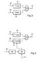
- FIG. 3shows a block diagram of the case for a hard crash.
- the integration time 16which is the time after the noise threshold has been exceeded and the integration of the acceleration signal A has begun, is fed to a block 17, in which It is checked whether the integration time is below the time t almost , which was determined experimentally to detect a hard crash. This means that the first belt tensioner stage has already been fired within this time. This is checked in the lower branch.
- a block 19is supplied with a signal 18 which indicates whether this first stage of the belt tensioner has been ignited. If this is the case, then the block 19 outputs a logical 1 and the block 17 then also outputs a logic 1 if the integration time is still below the time t almost .
- both functions 17 and 19are supplied to an AND gate 20, so that the AND gate 20 outputs only a logic 1 when both conditions are satisfied indicating a hard crash. So if there is a logical 1 in both, then a logic 1 is output as the output signal of the AND gate 20, which then indicates as a signal 21, that now also the second belt tensioner stage is to ignite immediately. In this case, therefore, there is a hard crash. Here no further signal analysis is performed, which would only lead to a delay.
- FIG. 4shows a block diagram of the case of a soft crash.
- a signal 22provides the integration time to a block 23 which checks whether this integration time is below a time t max .
- This time t maxis set to prevent the second belt tensioner stage from being triggered in a soft crash not only for a certain time that has elapsed, so as to avoid unnecessary triggering of this restraining means.
- the block 23therefore outputs only a logical 1 if the integration time is below this time t max .
- the output of the block 23is in turn supplied to an AND gate 26.
- a block 24is supplied with a signal 24, which is the integrated acceleration signal in the direction of travel. This integrated acceleration signal is compared in block 25 with the second threshold, ie the threshold for the second belt tensioner stage.
- the block 25If this signal is above the second threshold, then the block 25 outputs a logical 1, namely to the AND gate 26.
- the AND gate 26 as output signal 27only a logical 1 deliver when the integration time is below the time t max is and the second threshold has been exceeded.
- the second threshold 25, however,is calculated dynamically. This takes place in block 28, which is fed on the one hand by a signal 31, from which dynamic information emerges.
- static information 30which initially leads in block 29 to a first threshold value calculation, enters the threshold value calculation 28. This first threshold is fed to block 28, which then makes a modification of this threshold in response to the dynamic information.
- dynamic informationis calculated as the sensor signal
- static informationare those conditions that do not change during a crash, such as the position of the driver and passenger seats, the speed of the vehicle at crash, the relative speed compared to the obstacle before the first contact, and other such information.
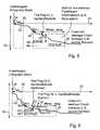
- FIG. 5shows a first typical crash course that occurs in a crash with a low crash severity.
- the crash severityis determined here by a signal derived from the acceleration, in this case by the speed signal.
- the crash severityis determined in particular by a feature analysis.
- the speed signal 43is shown here in a speed-time diagram. On the abscissa 32, the time is shown, while on the ordinate 33, the speed signal is shown.
- the integratorstarts because a noise threshold is exceeded here. From this point in time 34, the time interval is monitored until time t almost 35 to see if there is a hard crash. The condition is, as shown above, that in this time the first belt tensioner stage is ignited.
- the second belt tensioner stageis automatically ignited without carrying out any further signal analysis.
- the threshold for the first belt tensioner stageis reached and the first belt tensioner stage is ignited From time 36, the time is monitored until the time 38, because during this time, the second belt tensioner stage must be ignited, or there is such a crash with low crash severity before, for example, against a soft barrier that the use of the second belt tensioner stage is not necessary.
- the threshold for the driver for the second belt tensioner stagehas been reached and it will ignited the second belt tensioner stage.
- This threshold 39is composed once of the static information presented above and of an add-on, ie a surcharge, of further dynamic parameters. This is where the crash type detection in particular comes in. However, the threshold 40 for the passenger is not reached by the signal 43 during the time until time 38, so that the use of the second belt tensioner stage for the passenger is not necessary here.
- FIG. 6shows a crash course with high crash severity.
- the same elements, which are shown in Figure 5,are here designated by the same reference numerals and are not explained in detail.
- the signal curve of the integrated acceleration signal 43again reaches such a level at time 36 that the first belt tensioner stage is triggered. Wiedemm is monitored until time 38, whether the second belt tensioner stage is triggered.
- the threshold for the passengeris already exceeded by the signal 43 at the time 41, so that the second Gurtshaffertress for the passenger is triggered here.
- the threshold 40is here namely at the time 41 due to the dynamic information lowered by the crash signal and so it comes to an exceeding of this threshold. In the further waveform, you can see that the threshold 40 is raised again.
- the threshold for the driver 39is exceeded at the time 42 by the signal 43. Again, the waveform determines an adaptation of the threshold. Thus, at time 42, the second belt tensioner stage is triggered for the driver. Overall, here is a typical course for a crash with high crash severity on impact, for example, against a hard barrier.
- the requirements for triggering the second belt tensioner stageare generally different for the driver and front passenger. So the second belt tensioner stage is to be ignited, for example, for the driver even at a lower crash severity, as in the passenger to prevent knee injuries. This is especially true for a seating position that is very close to the steering wheel.
- the risk of injury to the passenger by slipping underneath the belt, the so-called submarining, on the other hand,can be relevant only for larger crash severity.
Landscapes
- Engineering & Computer Science (AREA)
- Mechanical Engineering (AREA)
- Air Bags (AREA)
- Automotive Seat Belt Assembly (AREA)
- Tyre Moulding (AREA)
Description
Translated fromGermanDie Erfindung geht aus von einem Verfahren zur Ansteuerung eines zweistufigen Gurtstraffers nach der Gattung des unabhängigen Patentanspruchs. Ein solches Verfahren is aus der US 5 400 487 A bekannt.The invention is based on a method for controlling a two-stage belt tensioner according to the preamble of the independent claim. Such a method is known from US 5,400,487 A.
Das erfindungsgemäße Verfahren zur Ansteuerung eines zweistufigen Gurtstraffers weist die Merkmale des Kennzeichnenden Teil des Anspruchs 1 auf.The inventive method for controlling a two-stage belt tensioner has the features of the characterizing part of
Durch die in den abhängigen Ansprüchen aufgeführten Maßnahmen und Weiterbildungen sind vorteilhafte Verbesserungen des im unabhängigen Patentanspruch angegebenen Verfahrens zur Ansteuerung eines zweistufigen Gurtstraffers möglich.The measures and refinements recited in the dependent claims advantageous improvements of the independent claim method for controlling a two-stage belt tensioner are possible.
Besonders vorteilhaft ist, dass im Falle von harten Crashereignissen die zweite Gurtstrafferstufe mit einer minimalen Verzögerung hinter der ersten gezündet wird, während bei weicheren bzw. langsameren Crashes genügend Zeit für eine detaillierte Auswertung der Signale, die von der Beschleunigung abgeleitet werden, zur Verfügung steht. Diese Signale können von einem Sensor im Zentralgerät und von ausgelagerten Satellitensensoren, wie es beispielsweise Upfrontsensoren sind, stammen.It is particularly advantageous that in the case of hard crash events, the second belt tensioner stage is ignited with a minimum delay behind the first, while at softer or slower crashes enough time for a detailed evaluation of the signals derived from the acceleration available stands. These signals can come from a sensor in the central unit and from remote satellite sensors, such as upfront sensors.
Das erfindungsgemäße Verfahren ermöglicht, dass der Einsatz der zweiten Gurtstrafferstufe, die hier üblicher Weise pyrotechnisch gezündet wird, beispielsweise zwischen der ersten und zweiten Airbagstufe liegt, so dass sich eine Gesamtabfolge der Rückhaltemittel im Falle eines Frontalcrashes ergibt:The method according to the invention makes it possible for the use of the second belt tensioner stage, which is pyrotechnically ignited here, to lie, for example, between the first and second airbag stages, resulting in an overall sequence of the retaining means in the event of a frontal crash:
Gurtstraffer erste Stufe - Airbag erste Stufe - Gurtstraffer zweite Stufe - Airbag zweite Stufe.Belt tensioner first stage - airbag first stage - belt tensioner second stage - airbag second stage.
Zeitlich soll die zweite Gurtstrafferstufe jedoch möglichst vor der ersten Airbagstufe gezündet werden, so dass das erfindungsgemäße Verfahren die Zeitbedingungen relativ zur ersten Gurtstrafferstufe auswertet.In terms of time, however, the second belt tensioner stage should be fired as far as possible before the first airbag stage, so that the method according to the invention evaluates the time conditions relative to the first belt tensioner stage.
Das erfindungsgemäße Verfahren vergleicht das Geschwindigkeitssignal in Fahrtrichtung, also den sogenannten X-Integrator, der das Beschleunigungssignal in Fahrtrichtung integriert, mit einer festen Schwelle. Diese Schwelle ist im allgemeinen verschieden für Fahrer, Beifahrer und gegebenenfalls auch für Rücksitzpositionen. Weiterhin können unterschiedliche Schwellen für unterschiedliche statische Bedingungen, unter denen der Crash stattfindet, angelegt werden. Solche statischen Bedingungen sind Bedingungen, die sich während des Crashes nicht ändern. Dazu gehören zum Beispiel die Position des Fahrer- bzw. Beifahrersitzes, d.h. große bzw. kleine Distanz zum Lenkrad, bzw. dem Armaturenbrett, die Geschwindigkeit des Fahrzeugs bei Crashbeginn, die in verschiedene Klassen eingeteilt werden kann, die Relativgeschwindigkeit zum Hindernis vor dem ersten Kontakt, die mittels Precrashsensorik ermittelt wird und andere Informationen, die im Fahrzeug verfügbar sind.The method according to the invention compares the speed signal in the direction of travel, that is to say the so-called X integrator, which integrates the acceleration signal in the direction of travel, with a fixed threshold. This threshold is generally different for driver, front passenger and possibly also for rear seat positions. Furthermore, different thresholds can be applied for different static conditions under which the crash takes place. Such static conditions are conditions that do not change during the crash. These include, for example, the position of the driver's or front passenger's seat, i. large or small distance to the steering wheel or the dashboard, the speed of the vehicle at the start of the crash, which can be divided into different classes, the relative speed to the obstacle before the first contact, which is determined by Precrashsensorik and other information available in the vehicle are.
Dynamische Informationen aus Zusatzfunktionen, die während des Crashes aus Sensorsignalen berechnet werden, können die Schwellen zeitabhängig modifizieren, d.h. es wird eine Adaption vorgenommen.Dynamic information from additional functions computed from sensor signals during the crash may modify the thresholds time-dependent, i. An adaptation is made.
Das erfindungsgemäße Verfahren wird nur bis zu einem maximalen Zeitpunkt nach Überschreiten der Schwelle für die erste Gurtstrafferstufe, also einer maximalen Verzögerung zwischen der ersten und zweiten Stufe, berechnet, da sonst auch Crashes, die die geforderte Schwere für das Auslösen der zweiten Gurtstrafferstufe nicht erreichen, die Integratorschwelle für die zweite Gurtstrafferstufe in dem späteren Crashverlauf letztlich erreichen würden. Für Crashes, die sich erst spät im Crashverlauf als so schwer erweisen, dass die zweite Airbagstufe ausgelöst werden muss, zum Beispiel bei Crashes gegen eine weiche Barriere, kann es sich als sinnvoll erweisen, ein gleichzeitiges Auslösen der zweiten Gurtstrafferstufe mit der zweiten Airbagstufe zu gewährteisten.The inventive method is only up to a maximum time after exceeding the threshold for the first belt tensioner stage, so a maximum Delay between the first and second stage calculated, otherwise crashes that do not reach the required severity for triggering the second belt tensioner stage would reach the Integratorschwelle for the second belt tensioner stage in the later crash course ultimately. For crashes that prove to be so late in the crash as so difficult that the second airbag stage must be triggered, for example in crashes against a soft barrier, it may prove useful to guarantee a simultaneous triggering of the second belt tensioner stage with the second airbag stage ,
Letztlich ist es auch von Vorteil, dass mit der zweiten Gurtstrafferstufe gleichzeitig ein Knieairbag angesteuert wird. Die zweite Gurtstrafferstufe kann dabei als eine zweite pyrotechnische Zündung in Hüft- oder in Scliulterhöhe, als auch als Bag-in-Belt verbaut sein.Ultimately, it is also advantageous that at the same time a knee airbag is controlled with the second belt tensioner. The second belt tensioner stage can be installed as a second pyrotechnic ignition in hip or Scliulterhöhe, as well as a bag-in-belt.
Ein Ausführungsbeispiele der Erfindung sind in der Zeichnung dargestellt und werden in der nachfolgenden Beschreibung näher erläutert.An embodiment of the invention are illustrated in the drawings and will be explained in more detail in the following description.
Es zeigen
Figur 1- ein Blockschaltbild des erfindungsgemäßen Verfahrens,
Figur 2- ein Flussdiagramm des erfindungsgemäßen Verfahrens,
Figur 3- eine Teilfunktion des erfindungsgemäßen Verfahrens für Härtecrashs,
Figur 4- eine Teilfunktion des erfindungsgemäßen Verfahrens für weiche Crashs, '
Figur 5- einen ersten Signalverlauf des integrierten Beschleunigungssignals in x-Richtung und
Figur 6- einen zweiten Signalverlauf des integrierten Beschleunigungssignals in x-Richtung.
- FIG. 1
- a block diagram of the method according to the invention,
- FIG. 2
- a flow chart of the method according to the invention,
- FIG. 3
- a partial function of the method according to the invention for hardness crashes,
- FIG. 4
- a partial function of the method according to the invention for soft crashes,
- FIG. 5
- a first waveform of the integrated acceleration signal in the x-direction and
- FIG. 6
- a second waveform of the integrated acceleration signal in the x direction.
Heutige Systems sind darauf ausgelegt, in Abhängigkeit von der detektierten Crashschwere ein einstufiges Gurtstraffersystem anzusteuern. Der dazu notwendige Auslöseentscheidungsalgorithmus wird folgendermaßen durchgefiihrt:Today's systems are designed to control a single-stage belt tensioner system depending on the detected crash severity. The triggering decision algorithm necessary for this is carried out as follows:
Das Beschleunigungssignal des zentralen Steuergeräts durchläuft zwei zentrale Pfade. Im oberen Pfad wird das Integral der Beschleunigung in x-Richtung, also in Fahrtrichtung, das ist dann die abgebaute Geschwindigkeit im Crashverlauf, berechnet. Während im unteren Pfad mittels verschiedener Filterfunktionen crash- und fahrzeugspezifische Merkmale aus dem Beschleunigungssignal ebenfalls in Fahrtrichtung extrahiert und in eine beschleunigungsabhängige Auslöseschwelle umgerechnet werden. Die Auslöseentscheidung entsteht dann durch Vergleich des Integratorwertes mit der Auslöseschwelle.The acceleration signal of the central control unit passes through two central paths. In the upper path is the integral of the acceleration in the x-direction, ie in the direction of travel, which is then the degraded speed in the crash course, calculated. While in the lower path by means of various filter functions crash and vehicle-specific features from the acceleration signal also extracted in the direction of travel and converted into an acceleration-dependent triggering threshold. The triggering decision is then created by comparing the integrator value with the triggering threshold.
Erfindungsgemäß wird nun in dieses Konzept die Auslösung einer zweiten Gurtstrafferstufe integriert.According to the invention, the triggering of a second belt tensioner stage is now integrated into this concept.
Figur 1 zeigt als Blockschaltbild den grundsätzlichen Ablauf bei der Auswertung eines Beschleunigungssignals a, das im Block 1 durch einen Beschleunigungssensor gewonnen wird. Dieses Beschleunigungssignal wird in Block 2 integriert zu einem Geschwindigkeitssignal, das bei einem Crash der abgebauten Geschwindigkeit entspricht. Im unteren Pfad in Block 3 wird das gleiche Beschleunigungssignal durch einen Filter 3 gefiltert um dann in Verbindung mit anderen fahrzeugspezifischen Merkmalen aus diesem gefilterten Beschleunigungssignal eine Auslöseschwelle für das integrierte Beschleunigungssignal zu bestimmen. Diese Auslöseschwelle, die zeitabhängig bestimmt wird, wird einem Schwellwertentscheider 5 als Schwelle zur Verfiigung gestellt. Der Schwellwertentscheider 5 vergleicht nun das integrierte Beschleunigungssignal aus dem Block 2 mit dieser Schwelle. Liegt das integrierte Beschleunigungssignal über dieser Schwelle, dann wird auf einen Auslösefall erkannt. Dies wird dann einem Block 6 zugeführt, der für die Ansteuerung von Rückhaltemitteln verantwortlich ist. Um die Rückhaltemittel letztlich auszulösen, ist noch das Signal eines Plausibilitätssensors erforderlich. Dazu kann beispielsweise ein Sicherheitsschalter oder ein weiterer Beschleunigungssensor eingesetzt werden.Figure 1 shows a block diagram of the basic sequence in the evaluation of an acceleration signal a, which is obtained in
Figur 2 zeigt nun den Ablauf des erfindungsgemäßen Verfahrens. In Verfahrensschritt 7 wird das Beschleunigungssignal a in Block 1 erzeugt. In Verfahrensschritt 8 wird mittels einer Schwellwertentscheidung im Schwellwertentscheider 5 entschieden, ob ein Auslösefall vorliegt. Ist dies nicht der Fall, wird zu Verfahrensschritt 7 zurückgesprungen. Ist das jedoch der Fall, dann wird in Verfahrensschritt 9 überprüft, ob zusätzlich zu der nun auslösenden ersten Gurtstrafferstufe auch die zweite Gurtstrafferstufe ausgelöst werden soll. D.h. es findet in Schritt 9 die Prüfung darauf hin statt, ob ein harter Crash vorliegt. In einem solchen Fall muss die zweite Gurtstrafferstufe sofort ausgelöst werden und eine weitere Signalanalyse ist nicht mehr notwendig. Wird also ein harter Crash erkannt, dann wird zu Verfahrensschritt 10 gesprungen und die zweite Gurtstrafferstufe ausgelöst. Parallel dazu und danach berechnet ein weiterer Algorithmus die Auslöseentscheidung für die Airbags.FIG. 2 now shows the sequence of the method according to the invention. In
In die Ansteuerung des Gurtstraffers gehen auch Daten über den Insassen ein. D.h. ist der Platz überhaupt besetzt, welche Gewichtsparameter weist die Person auf und auf welchem Platz sitzt sie. Es können mehr oder weniger als diese drei Parameter verwendet werden. Sitzt die Person auf dem Fahrersitz, dann müssen die Gurtstraffer früher ausgelöst werden, da der Abstand zum Lenkrad, also zu einem Aufprallobjekt für die Person, näher ist als für den Beifahrer zur Armatur. Dies sind statische Parameter, die die Auslöseschwellen im Block 4 bestimmen.The activation of the belt tensioner also includes data about the occupants. That is the place at all occupied, what weight parameters does the person and on what place does she sit. More or less than these three parameters can be used. If the person is seated in the driver's seat, then the belt tensioners must be triggered earlier because the distance to the steering wheel, ie to an impact object for the person, is closer than for the passenger to the valve. These are static parameters that determine the tripping thresholds in
Wurde in Verfahrensschritt 9 erkannt, dass kein harter Crash vorliegt, also dass nur die erste Stufe ausgelöst wird, dann erfolgt in Verfahrensschritt 11 eine detaillierte Signalanalyse des integrierten Beschleunigungssignals. Es kann auch hier das Beschleunigungssignal an sich ausgewertet werden. Ergibt in Verfahrensschritt 12 die Signalanalyse, dass nun auch die zweite Gurtstrafferstufe ausgelöst werden muss, da beispielsweise der weiche Crash sich als so gefährlich erweist, dass die Person mit der zweiten Gurtstrafferstufe zu schützen ist, dann wird zu Verfahrensschritt 50 gesprungen, um die zweite Gurtstrafferstufe auszulösen. Wurde jedoch durch die Signalanalyse in Verfahrensschritt 12 keine Auslösung für die zweite Gurtstrafferstufe ermittelt, dann wird zu Verfahrensschritt 13 gesprungen, um die zweite Airbagstufe zu überwachen. Wurde nun in Verfahrensschritt 14 festgestellt, dass die zweite Airbagstufe ausgelöst wird, dann wird zu Verfahrensschritt 60 gesprungen, um auch die zweite Gurrstrafferstufe auszulösen. Wurde in Verfahrensschritt 14 erkannt, dass die zweite Airbagstufe nicht ausgelöst wird, wird zu Verfahrensschritt 15 gesprungen, um das erfindungsgemäße Verfahren hier zu beenden.If it was detected in method step 9 that there is no hard crash, ie that only the first stage is triggered, then in method step 11 a detailed signal analysis of the integrated acceleration signal takes place. It is also possible here to evaluate the acceleration signal per se. If, in
Figur 3 zeigt als Blockschaltbild den Fall für einen harten Crash. Die Integrationszeit 16, das ist die Zeit, nachdem die Rauschschwelle überschritten wurde und die Integration des Beschleunigungssignals A begonnen hat, wird einem Block 17 zugefiihrt, in dem überprüft wird, ob die Integrationszeit unter der Zeit tfast liegt, die experimentell festgelegt wurde, um einen harten Crash zu erkennen. D.h. innerhalb dieser Zeit muss die erste Gurtstrafferstufe bereits gezündet worden sein. Dies wird im unteren Zweig überprüft. Einem Block 19 wird ein Signal 18 zugeführt, das anzeigt, ob diese erste Stufe des Gurtstraffers gezündet wurde. Ist das der Fall, dann gibt der Block 19 eine logische 1 ab und der Block 17 gibt dann auch eine logische 1 ab, wenn die Integrationszeit noch unter der Zeit tfast liegt. Die Ausgänge beider Funktionen 17 und 19 werden einem UND-Gatter 20 zugeführt, so dass das UND-Gatter 20 nur eine logische 1 abgibt, wenn beide Bedingungen erfüllt sind, die einen harten Crash anzeigen. Liegt bei beiden also eine logische 1 vor, dann wird als Ausgangssignal des UND-Gatters 20 einen logische 1 abgegeben, die als Signal 21 dann anzeigt, dass nun auch die zweite Gurtstrafferstufe sofort zu zünden ist. In diesem Fall liegt demnach ein harter Crash vor. Hier wird keine weitere Signalanalyse durchgeführt, die nur zu einer Verzögerung führen würde.FIG. 3 shows a block diagram of the case for a hard crash. The
Figur 4 zeigt als Blockdiagramm den Fall eines weichen Crashes. Ein Signal 22 liefert die Integrationszeit einem Block 23, der überprüft, ob diese Integrationszeit unterhalb einer Zeit tmax liegt. Diese Zeit tmax wird festgelegt, um zu verhindern, dass bei einem weichen Crash die zweite Gurtstrafferstufe nicht nur wegen einer bestimmten Zeit, die abgelaufen ist, ausgelöst wird, um so ein unnötiges Auslösen dieses Rückhaltemittels zu vermeiden. Der Block 23 gibt demnach nur eine logische 1 ab, wenn die Integrationszeit unterhalb dieser Zeit tmax liegt. Das Ausgangssignal des Blocks 23 wird wiederum einem UND-Gatter 26 zugeführt. Einem Block 25 wird ein Signal 24 zugefiihrt, das das integrierte Beschleunigungssignal in Fahrtrichtung ist. Dieses integrierte Beschleunigungssignal wird im Block 25 mit der zweiten Schwelle, also der Schwelle für die zweite Gurtstrafferstufe verglichen. Liegt dieses Signal über der zweiten Schwelle, dann gibt der Block 25 eine logische 1 ab, und zwar an das UND-Gatter 26. Damit wird das UND-Gatter 26 als Ausgangssignal 27 nur dann eine logische 1 abgeben, wenn die Integrationszeit unterhalb der Zeit tmax liegt und die zweite Schwelle überschritten wurde. Die zweite Schwelle 25 wird jedoch dynamisch berechnet. Dies erfolgt im Block 28, der einerseits durch ein Signal 31 gespeist wird, aus dem dynamische Informationen hervorgehen. Andererseits gehen in die Schwellwertberechnung 28 statische Informationen 30 ein, die zunächst im Block 29 zu einer ersten Schwellwertberechnung führen. Diese erste Schwelle wird dem Block 28 zugeführt, der dann in Abhängigkeit von den dynamischen Informationen eine Modifikation dieser Schwelle vornimmt. Wie oben dargestellt, werden dynamische Informationen als Sensorsignal berechnet, während die statischen Informationen solche Bedingungen sind, die sich während eines Crashes nicht ändern, wie die Position des Fahrer- und Beifahrersitzes, die Geschwindigkeit des Fahrzeugs bei Crashbeginn, die Relativgeschwindigkeit im Vergleich zum Hindernis vor dem ersten Kontakt und andere solche Informationen.FIG. 4 shows a block diagram of the case of a soft crash. A
Gibt nun das UND-Gatter 26 eine logische 1 als Signal 27 ab, dann wird die zweite Gurtstrafferstufe gezündet.Is now the AND
Diese Signale, ob ein Gurtstraffer gezündet wurde, wird üblicher Weise durch Flaggen angezeigt, die in Registern gesetzt wurden. Das erfmdungsgemätie Verfahren läuft üblicherweise auf einem Prozessor im zentralen Steuergerät ab. Als ein solcher Prozessor kann ein Mikrokontroller verwendet werden. Es ist jedoch auch möglich, dass durch eine verteilte Intelligenz dieser Algorithmus berechnet wird. D.h., den Gurtstraffern ist in diesem Fall ein eigener Prozessor zugeordnet.These signals, whether a belt tensioner has been fired, are usually indicated by flags that have been set in registers. The erfmdungsgemätie method usually runs on a processor in the central control unit. As such a processor, a microcontroller can be used. However, it is also possible that this algorithm is calculated by a distributed intelligence. That is, the belt tensioners in this case is assigned its own processor.
Figur 5 zeigt einen ersten typischen Crashverlauf, der bei einem Crash mit niedriger Crashschwere auftritt. Die Crashschwere wird hier durch ein von der Beschleunigung abgeleitetes Signal, in diesem Fall durch das Geschwindigkeitssignal, bestimmt. Die Crashschwere wird dabei insbesondere durch eine Merkmalsanalyse festgelegt. Das Geschwindigkeitssignal 43 ist hier in einem Geschwindigkeits-Zeit-Diagramm dargestellt. Auf der Abszisse 32 ist die Zeit dargestellt, während auf der Ordinate 33 das Geschwindigkeitssignal dargestellt ist. Zum Zeitpunkt 34 startet der Integrator, da hier eine Rauschschwelle überschritten wird. Von diesem Zeitpunkt 34 an wird das Zeitintervall bis zur Zeit tfast 35 überwacht, um festzustellen, ob ein harter Crash vorliegt. Die Bedingung ist, wie oben dargestellt, dass in dieser Zeit die erste Gurtstrafferstufe gezündet wird. In einem solchen Fall wird nach dem Zünden der ersten Gurtstrafferstufe nach der Zeit tdelay, die vorgegeben ist, automatisch die zweite Gurtstrafferstufe gezündet, ohne eine weitere Signalanalyse durchzuführen. Dies ist jedoch hier nicht der Fall. Im weiteren Verlauf zum Zeitpunkt 36 wird der Schwellwert für die erste Gurtstrafferstufe erreicht und die erste Gurtstrafferstufe wird gezündet Ab dem Zeitpunkt 36 wird die Zeitspanne bis zum Zeitpunkt 38 überwacht, denn in dieser Zeit muss die zweite Gurtstrafferstufe gezündet werden, oder es liegt ein solcher Crash mit niedriger Crashschwere vor, beispielsweise gegen eine weiche Barriere, dass der Einsatz der zweiten Gurtstrafferstufe nicht notwendig ist. Zum Zeitpunkt 37 wurde jedoch die Schwelle für den Fahrer für die zweite Gurtstrafferstufe erreicht, und es wird die zweite Gurtstrafferstufe gezündet. Diese Schwelle 39 setzt sich einmal aus der statischen Information zusammen, die oben dargestellt wurde, und einem Add-On, also einem Zuschlag, aus weiteren dynamischen Parametern. Hier geht dann insbesondere die Crashtyperkennung ein. Die Schwelle 40 für den Beifahrer wird durch das Signal 43 während der Zeit bis zum Zeitpunkt 38 jedoch nicht erreicht, so dass hier der Einsatz der zweiten Gurtstrafferstufe für den Beifahrer nicht notwendig ist.FIG. 5 shows a first typical crash course that occurs in a crash with a low crash severity. The crash severity is determined here by a signal derived from the acceleration, in this case by the speed signal. The crash severity is determined in particular by a feature analysis. The
Figur 6 zeigt einen Crashverlauf mit hoher Crashschwere. Die gleichen Elemente, die in Figur 5 dargestellt sind, sind hier mit den gleichen Bezugszeichen bezeichnet und werden nicht näher erläutert. Der Signalverlauf des integrierten Beschleunigungssignals 43 erreicht hier wiederum zum Zeitpunkt 36 eine solche Schwere, dass die erste Gurtstrafferstufe ausgelöst wird. Wiedemm wird bis zum Zeitpunkt 38 überwacht, ob die zweite Gurtstrafferstufe ausgelöst wird. Hier wird jedoch bereits zum Zeitpunkt 41 die Schwelle für den Beifahrer durch das Signal 43 überschritten, so dass die zweite Gurtshafferstufe für den Beifahrer hier ausgelöst wird. Die Schwelle 40 wird hier nämlich zum Zeitpunkt 41 aufgrund der dynamischen Informationen durch das Crashsignal abgesenkt und so kommt es zu einem Überschreiten dieser Schwelle. Im weiteren Signalverlauf sieht man, dass die Schwelle 40 wieder angehoben wird. Die Schwelle für den Fahrer 39 wird erst zum Zeitpunkt 42 durch das Signal 43 überschritten. Auch hier bestimmt der Signalverlauf eine Adaption der Schwelle. Damit wird zum Zeitpunkt 42 auch die zweite Gurtstrafferstufe für den Fahrer ausgelöst. Insgesamt wird hier ein typischer Verlauf für einen Crash mit hoher Crashschwere beim Aufprall beispielsweise gegen eine harte Barriere dargestellt.FIG. 6 shows a crash course with high crash severity. The same elements, which are shown in Figure 5, are here designated by the same reference numerals and are not explained in detail. The signal curve of the integrated
Die Anforderungen für das Auslösen der zweiten Gurtstrafferstufe sind im Allgemeinen unterschiedlich für Fahrer und Beifahrer. So soll die zweite Gurtstrafferstufe beispielsweise für den Fahrer schon bei einer geringeren Crashschwere gezündet werden, als beim Beifahrer, um Knieverletzungen zu verhindern. Dies gilt besonders für eine Sitzposition, die sehr nahe am Lenkrad ist. Die Verletzungsgefahr beim Beifahrer durch Durchrutschen unterhalb des Gurtes, das sogenannte Submarining, kann dagegen erst bei größeren Crashschweren relevant werden.The requirements for triggering the second belt tensioner stage are generally different for the driver and front passenger. So the second belt tensioner stage is to be ignited, for example, for the driver even at a lower crash severity, as in the passenger to prevent knee injuries. This is especially true for a seating position that is very close to the steering wheel. The risk of injury to the passenger by slipping underneath the belt, the so-called submarining, on the other hand, can be relevant only for larger crash severity.
Claims (1)
- Method for actuating a two-stage seatbelt preload device, with the second stage of the seatbelt preload device being controlled as a function of the severity of a crash and a sitting position, with the severity of a crash being determined by at least one signal which is derived from a determined acceleration during a collision, and with the sitting position determining the evaluation of the at least one signal,characterized in that, if the severity of a crash indicates a hard crash, the second stage is actuated after a predetermined time after the first stage is activated.
Applications Claiming Priority (3)
| Application Number | Priority Date | Filing Date | Title |
|---|---|---|---|
| DE10230483ADE10230483A1 (en) | 2002-07-06 | 2002-07-06 | Procedure for controlling a two-stage belt tensioner |
| DE10230483 | 2002-07-06 | ||
| PCT/DE2003/001435WO2004005080A2 (en) | 2002-07-06 | 2003-05-06 | Method for controlling the preload device of a two-level belt |
Publications (2)
| Publication Number | Publication Date |
|---|---|
| EP1536992A2 EP1536992A2 (en) | 2005-06-08 |
| EP1536992B1true EP1536992B1 (en) | 2006-05-03 |
Family
ID=29723756
Family Applications (1)
| Application Number | Title | Priority Date | Filing Date |
|---|---|---|---|
| EP03735273AExpired - LifetimeEP1536992B1 (en) | 2002-07-06 | 2003-05-06 | Method for controlling the preload device of a two-level belt |
Country Status (4)
| Country | Link |
|---|---|
| US (1) | US7416042B2 (en) |
| EP (1) | EP1536992B1 (en) |
| DE (2) | DE10230483A1 (en) |
| WO (1) | WO2004005080A2 (en) |
Families Citing this family (37)
| Publication number | Priority date | Publication date | Assignee | Title |
|---|---|---|---|---|
| DE102004041425B3 (en)* | 2004-08-27 | 2005-10-06 | Bayerische Motoren Werke Ag | Restraint system for a motor vehicle |
| JP2006088899A (en)* | 2004-09-24 | 2006-04-06 | Takata Corp | Occupant crash protection device |
| US7370721B2 (en)* | 2004-12-03 | 2008-05-13 | Autoliv Asp, Inc. | Seatbelt tensioning device and method |
| GB2424983A (en)* | 2005-04-07 | 2006-10-11 | Autoliv Dev | Seatbelt pretensioner control system |
| GB2424982A (en)* | 2005-04-07 | 2006-10-11 | Autoliv Dev | Seatbelt pretensioner dependent on steering rate |
| DE102005035861B4 (en)* | 2005-07-30 | 2014-07-31 | GM Global Technology Operations LLC (n. d. Ges. d. Staates Delaware) | Belt tightening system for a motor vehicle and safety system with such a belt tightening system |
| DE102005035849A1 (en) | 2005-07-30 | 2007-02-08 | GM Global Technology Operations, Inc., Detroit | Safety arrangement with a belt tensioner, motor vehicle with such a safety arrangement, and method for controlling a belt tensioner |
| DE102005035863A1 (en) | 2005-07-30 | 2007-02-01 | GM Global Technology Operations, Inc., Detroit | Method for controlling a belt tensioner and safety arrangement with a belt tensioner |
| DE102005035862A1 (en) | 2005-07-30 | 2007-02-01 | GM Global Technology Operations, Inc., Detroit | Reversible seat-belt-pretensioner controlling method for use in motor vehicle, involves activating seal-belt-pretensioner when actual rotational rate of vehicle is greater than upper threshold value or smaller than lower threshold value |
| DE102007018645B4 (en)* | 2007-04-19 | 2012-06-14 | Autoliv Development Ab | Airbag system and method for operating an airbag system |
| DE102009024558B4 (en)* | 2009-06-08 | 2023-02-02 | Mercedes-Benz Group AG | Method for protecting a vehicle occupant in a vehicle seat of a vehicle |
| DE102015205244B3 (en)* | 2015-03-24 | 2015-12-10 | Bayerische Motoren Werke Aktiengesellschaft | Method for providing obstacle cards for vehicles |
| US10850645B2 (en) | 2018-05-04 | 2020-12-01 | Lear Corporation | Track assembly |
| US11358497B2 (en) | 2018-05-04 | 2022-06-14 | Lear Corporation | Track system having a rolling member |
| US10882420B2 (en) | 2019-03-08 | 2021-01-05 | Lear Corporation | Track assembly |
| US11040639B2 (en) | 2018-05-04 | 2021-06-22 | Lear Corporation | Track assembly |
| US10906431B2 (en) | 2018-05-04 | 2021-02-02 | Lear Corporation | Track assembly |
| US10926667B2 (en) | 2018-05-04 | 2021-02-23 | Lear Corporation | Track assembly |
| US12233756B2 (en) | 2018-05-04 | 2025-02-25 | Lear Corporation | Track system with a support member |
| US11040638B2 (en) | 2018-05-04 | 2021-06-22 | Lear Corporation | Track assembly |
| US11440482B2 (en) | 2018-12-10 | 2022-09-13 | Lear Corporation | Track assembly |
| US11225201B2 (en) | 2018-12-10 | 2022-01-18 | Lear Corporation | Track assembly |
| US11613220B2 (en) | 2018-12-17 | 2023-03-28 | Lear Corporation | Electrical assembly |
| US10855037B2 (en) | 2018-12-17 | 2020-12-01 | Lear Corporation | Support assembly with a support member and a track assembly |
| US11117538B2 (en) | 2018-12-17 | 2021-09-14 | Lear Corporation | Electrical assembly |
| US10950977B2 (en) | 2018-12-18 | 2021-03-16 | Lear Corporation | Track assembly for a vehicle component |
| US11975665B2 (en) | 2019-02-20 | 2024-05-07 | Lear Corporation | Electrical assembly |
| US11040653B2 (en) | 2019-02-25 | 2021-06-22 | Lear Corporation | Track assembly |
| US11807142B2 (en) | 2019-03-06 | 2023-11-07 | Lear Corporation | Electrical track assembly |
| US11299075B2 (en) | 2019-03-06 | 2022-04-12 | Lear Corporation | Electrical assembly |
| US11463083B2 (en) | 2019-10-04 | 2022-10-04 | Lear Corporation | Electrical system |
| US11634101B2 (en) | 2019-10-04 | 2023-04-25 | Lear Corporation | Removable component system |
| US11323114B2 (en) | 2019-10-04 | 2022-05-03 | Lear Corporation | Electrical system |
| US12055205B2 (en) | 2020-02-21 | 2024-08-06 | Lear Corporation | Track system with a support member |
| DE102021104018B4 (en) | 2020-02-21 | 2023-11-09 | Lear Corporation | Rail system with a support element, method for operating a rail system |
| US11505141B2 (en) | 2020-10-23 | 2022-11-22 | Lear Corporation | Electrical system with track assembly and support assembly |
| US12060034B1 (en) | 2023-02-03 | 2024-08-13 | B/E Aerospace, Inc. | Seat belt assemblies for mitigating spinal tension during free-flail |
Family Cites Families (6)
| Publication number | Priority date | Publication date | Assignee | Title |
|---|---|---|---|---|
| US5400487A (en)* | 1994-01-14 | 1995-03-28 | Automotive Systems Laboratory, Inc. | Variable inflation system for vehicle safety restraint |
| US5999871A (en)* | 1996-08-05 | 1999-12-07 | Delphi Technologies, Inc. | Control method for variable level airbag inflation |
| US5871236A (en)* | 1997-05-13 | 1999-02-16 | Trw Vehicle Safety Systems Inc. | Apparatus for pretensioning seat belt webbing |
| US6036225A (en)* | 1998-07-01 | 2000-03-14 | Trw Inc. | Method and apparatus for controlling an actuatable restraint device using crash severity indexing |
| US6549836B1 (en)* | 2000-06-07 | 2003-04-15 | Trw Inc. | Method and apparatus for controlling an actuatable restraint device using a velocity/displacement based safing function with immunity box |
| JP2006088899A (en)* | 2004-09-24 | 2006-04-06 | Takata Corp | Occupant crash protection device |
- 2002
- 2002-07-06DEDE10230483Apatent/DE10230483A1/ennot_activeWithdrawn
- 2003
- 2003-05-06WOPCT/DE2003/001435patent/WO2004005080A2/ennot_activeApplication Discontinuation
- 2003-05-06DEDE50303232Tpatent/DE50303232D1/ennot_activeExpired - Lifetime
- 2003-05-06USUS10/520,558patent/US7416042B2/ennot_activeExpired - Lifetime
- 2003-05-06EPEP03735273Apatent/EP1536992B1/ennot_activeExpired - Lifetime
Also Published As
| Publication number | Publication date |
|---|---|
| EP1536992A2 (en) | 2005-06-08 |
| DE50303232D1 (en) | 2006-06-08 |
| WO2004005080A3 (en) | 2004-03-11 |
| DE10230483A1 (en) | 2004-01-15 |
| US7416042B2 (en) | 2008-08-26 |
| WO2004005080A2 (en) | 2004-01-15 |
| US20060108787A1 (en) | 2006-05-25 |
Similar Documents
| Publication | Publication Date | Title |
|---|---|---|
| EP1536992B1 (en) | Method for controlling the preload device of a two-level belt | |
| DE19743009B4 (en) | Method and apparatus for single point sensing of front and side impact crash conditions | |
| DE10065518B4 (en) | Method for triggering restraint devices in a motor vehicle | |
| DE19945923B4 (en) | A method and apparatus for sensing side impact crash conditions using an enhanced save function | |
| EP1380474B1 (en) | Control arrangement for restraining means | |
| DE4330486C2 (en) | Method for deploying an airbag in a motor vehicle | |
| EP1409297B1 (en) | Method and device for controlling the triggering of a passive security system and the use thereof | |
| EP1523688A1 (en) | Device for monitoring the surroundings of a vehicle | |
| EP1160134B1 (en) | Occupant restraint system | |
| DE10123921C1 (en) | Occupant restraint system with a belt force limiting device | |
| EP1436172A1 (en) | Method for determining a decision for the triggering of restraint means in a vehicle | |
| WO2010142380A1 (en) | Method for controlling a restraint device for occupants of a vehicle | |
| DE102015116057B9 (en) | Occupant protection device for a vehicle | |
| DE10202908B4 (en) | Method and arrangement for determining a detection range of a pre-crash sensor system | |
| DE10157203B4 (en) | Passive security system | |
| DE10138764C1 (en) | Frontal impact detection system for use on motor vehicle uses forward-mounted longitudinal acceleration sensor and rearward-mounted longitudinal and lateral acceleration sensor | |
| EP1641655B1 (en) | Method for controlling an occupant protection device in a vehicle | |
| EP1796941A1 (en) | Method and device for controlling personal protection means | |
| DE10142925C1 (en) | Automobile passenger restraint system release method, uses evaluation of sensor signals differently weighted ahead and after unreliability time point | |
| DE19909296A1 (en) | Motor vehicle occupant protection system | |
| DE102007012461B4 (en) | Control device and method for controlling pedestrian protection devices | |
| EP1566312B1 (en) | Device for lateral collision recognition | |
| EP2036778B1 (en) | Method for controlling irreversible retaining means according to the seat position of a person | |
| DE10317637A1 (en) | Device for controlling an active headrest in a vehicle | |
| DE60305171T2 (en) | System arrangement and release logic for active pedals |
Legal Events
| Date | Code | Title | Description |
|---|---|---|---|
| PUAI | Public reference made under article 153(3) epc to a published international application that has entered the european phase | Free format text:ORIGINAL CODE: 0009012 | |
| 17P | Request for examination filed | Effective date:20050207 | |
| AK | Designated contracting states | Kind code of ref document:A2 Designated state(s):AT BE BG CH CY CZ DE DK EE ES FI FR GB GR HU IE IT LI LU MC NL PT RO SE SI SK TR | |
| GRAP | Despatch of communication of intention to grant a patent | Free format text:ORIGINAL CODE: EPIDOSNIGR1 | |
| RBV | Designated contracting states (corrected) | Designated state(s):DE FR GB | |
| GRAS | Grant fee paid | Free format text:ORIGINAL CODE: EPIDOSNIGR3 | |
| GRAA | (expected) grant | Free format text:ORIGINAL CODE: 0009210 | |
| AK | Designated contracting states | Kind code of ref document:B1 Designated state(s):DE FR GB | |
| PG25 | Lapsed in a contracting state [announced via postgrant information from national office to epo] | Ref country code:GB Free format text:LAPSE BECAUSE OF FAILURE TO SUBMIT A TRANSLATION OF THE DESCRIPTION OR TO PAY THE FEE WITHIN THE PRESCRIBED TIME-LIMIT Effective date:20060503 | |
| REG | Reference to a national code | Ref country code:GB Ref legal event code:FG4D Free format text:NOT ENGLISH | |
| REF | Corresponds to: | Ref document number:50303232 Country of ref document:DE Date of ref document:20060608 Kind code of ref document:P | |
| ET | Fr: translation filed | ||
| GBV | Gb: ep patent (uk) treated as always having been void in accordance with gb section 77(7)/1977 [no translation filed] | Effective date:20060503 | |
| PLBE | No opposition filed within time limit | Free format text:ORIGINAL CODE: 0009261 | |
| STAA | Information on the status of an ep patent application or granted ep patent | Free format text:STATUS: NO OPPOSITION FILED WITHIN TIME LIMIT | |
| 26N | No opposition filed | Effective date:20070206 | |
| REG | Reference to a national code | Ref country code:FR Ref legal event code:PLFP Year of fee payment:14 | |
| PGFP | Annual fee paid to national office [announced via postgrant information from national office to epo] | Ref country code:FR Payment date:20160523 Year of fee payment:14 | |
| REG | Reference to a national code | Ref country code:FR Ref legal event code:ST Effective date:20180131 | |
| PG25 | Lapsed in a contracting state [announced via postgrant information from national office to epo] | Ref country code:FR Free format text:LAPSE BECAUSE OF NON-PAYMENT OF DUE FEES Effective date:20170531 | |
| PGFP | Annual fee paid to national office [announced via postgrant information from national office to epo] | Ref country code:DE Payment date:20220725 Year of fee payment:20 | |
| REG | Reference to a national code | Ref country code:DE Ref legal event code:R071 Ref document number:50303232 Country of ref document:DE |