EP1536582B1 - Methods for changing the size of a jitter buffer and for time alignment, communications system, receiving end, and transcoder - Google Patents
Methods for changing the size of a jitter buffer and for time alignment, communications system, receiving end, and transcoderDownload PDFInfo
- Publication number
- EP1536582B1 EP1536582B1EP05004865AEP05004865AEP1536582B1EP 1536582 B1EP1536582 B1EP 1536582B1EP 05004865 AEP05004865 AEP 05004865AEP 05004865 AEP05004865 AEP 05004865AEP 1536582 B1EP1536582 B1EP 1536582B1
- Authority
- EP
- European Patent Office
- Prior art keywords
- transcoder
- jitter buffer
- speech data
- time
- communications system
- Prior art date
- Legal status (The legal status is an assumption and is not a legal conclusion. Google has not performed a legal analysis and makes no representation as to the accuracy of the status listed.)
- Expired - Lifetime
Links
- 238000000034methodMethods0.000titleclaimsabstractdescription57
- 238000004891communicationMethods0.000titleclaimsabstractdescription34
- 239000000872bufferSubstances0.000titleabstractdescription127
- 230000003139buffering effectEffects0.000claimsabstractdescription32
- 238000012545processingMethods0.000claimsabstractdescription18
- 230000003247decreasing effectEffects0.000claimsabstractdescription13
- 230000005540biological transmissionEffects0.000claimsdescription16
- 230000010363phase shiftEffects0.000claimsdescription15
- 238000009432framingMethods0.000claimsdescription10
- 230000008859changeEffects0.000abstractdescription8
- 230000001934delayEffects0.000abstractdescription3
- 238000004458analytical methodMethods0.000description30
- 238000010586diagramMethods0.000description30
- 230000015572biosynthetic processEffects0.000description28
- 238000003786synthesis reactionMethods0.000description28
- 238000013459approachMethods0.000description25
- 230000003044adaptive effectEffects0.000description23
- 230000007423decreaseEffects0.000description17
- 230000000694effectsEffects0.000description9
- 230000004048modificationEffects0.000description9
- 238000012986modificationMethods0.000description9
- 230000006870functionEffects0.000description8
- 230000007704transitionEffects0.000description7
- 230000003111delayed effectEffects0.000description4
- 230000002238attenuated effectEffects0.000description3
- 230000006835compressionEffects0.000description3
- 238000007906compressionMethods0.000description3
- 230000008569processEffects0.000description3
- 238000006243chemical reactionMethods0.000description2
- 230000006866deteriorationEffects0.000description2
- 230000001360synchronised effectEffects0.000description2
- 230000008901benefitEffects0.000description1
- 238000011156evaluationMethods0.000description1
- 230000007246mechanismEffects0.000description1
- 238000010295mobile communicationMethods0.000description1
- 238000002715modification methodMethods0.000description1
- 230000006855networkingEffects0.000description1
- 230000009467reductionEffects0.000description1
- 230000010076replicationEffects0.000description1
- 230000003362replicative effectEffects0.000description1
- 238000005070samplingMethods0.000description1
- 238000011524similarity measureMethods0.000description1
- 230000005236sound signalEffects0.000description1
Images


Classifications
- H—ELECTRICITY
- H04—ELECTRIC COMMUNICATION TECHNIQUE
- H04W—WIRELESS COMMUNICATION NETWORKS
- H04W88/00—Devices specially adapted for wireless communication networks, e.g. terminals, base stations or access point devices
- H04W88/18—Service support devices; Network management devices
- H04W88/181—Transcoding devices; Rate adaptation devices
- G—PHYSICS
- G10—MUSICAL INSTRUMENTS; ACOUSTICS
- G10L—SPEECH ANALYSIS TECHNIQUES OR SPEECH SYNTHESIS; SPEECH RECOGNITION; SPEECH OR VOICE PROCESSING TECHNIQUES; SPEECH OR AUDIO CODING OR DECODING
- G10L19/00—Speech or audio signals analysis-synthesis techniques for redundancy reduction, e.g. in vocoders; Coding or decoding of speech or audio signals, using source filter models or psychoacoustic analysis
- G—PHYSICS
- G10—MUSICAL INSTRUMENTS; ACOUSTICS
- G10L—SPEECH ANALYSIS TECHNIQUES OR SPEECH SYNTHESIS; SPEECH RECOGNITION; SPEECH OR VOICE PROCESSING TECHNIQUES; SPEECH OR AUDIO CODING OR DECODING
- G10L21/00—Speech or voice signal processing techniques to produce another audible or non-audible signal, e.g. visual or tactile, in order to modify its quality or its intelligibility
- G10L21/04—Time compression or expansion
- H—ELECTRICITY
- H04—ELECTRIC COMMUNICATION TECHNIQUE
- H04J—MULTIPLEX COMMUNICATION
- H04J3/00—Time-division multiplex systems
- H04J3/02—Details
- H04J3/06—Synchronising arrangements
- H04J3/062—Synchronisation of signals having the same nominal but fluctuating bit rates, e.g. using buffers
- H04J3/0632—Synchronisation of packets and cells, e.g. transmission of voice via a packet network, circuit emulation service [CES]
Definitions
- the inventionrelates to a method for carrying out a time alignment in a transcoder of a radio communications system, which time alignment is used for decreasing a buffering delay , said buffering delay resulting from buffering speech data encoded by said transcoder before transmitting said speech data over a radio interface of said radio communications system in order to compensate for a phase shift in a framing of said speech data in said transcoder and at said radio interface. Further, the invention relates to such a radio communications system and to a transcoder for a radio communications system and to an apparatus.
- VoIPvoice over IP
- IP telephony or voice over IPenables users to transmit audio signals like voice over the Internet Protocol. Sending voice over the internet is done by inserting speech samples or compressed speech into packets. The packets are then routed independently from each other to their destination according to the IP-address included in each packet.
- IP telephonyOne drawback in IP telephony is the availability and performance of networks. Although the local networks might be stable and predictable, the Internet is often congested and there are no guarantees that packets are not lost or significantly delayed. Lost packets and long delays have an immediate effect on speech quality, reciprocity and the pace of conversation.
- the packetsBecause of the independent routing of the packets, the packets moreover take variable times to go through the network. The variation in packet arrival times is called jitter.
- the jitter buffercan be employed.
- the jitter buffercan be located before or after a decoder used at the receiving end for decoding the speech which was encoded for transmission. In the jitter buffer, the right order of packets can then be assured by checking sequence numbers contained in the packets. Equally contained timestamps can further be used to determine the jitter level in the network and for compensating for the jitter in play out.
- the size of the jitter bufferhas a contrary effect on the number of packets that are lost and on the end-to-end delay. If the jitter buffer is very small, many packets are lost because they have arrived after their playout point. On the other hand, if the jitter buffer is very large an excessive end-to-end delay appears. Both, packet loss and end-to-end delay, have an effect on speech quality. Therefore, the size of the jitter buffer has to result in an acceptable value for both, packet loss and delay. Since both can vary in time, adaptive jitter buffers have to be employed in order to be able to continuously guarantee a good compromise for the two factors. The size of an adaptive jitter buffer can be changed based on measured delays of received speech packets and measured delay variances between received speech packets.
- Known methodsadjust the jitter buffer size in the beginning of a talkspurt. At the beginning of a talkspurt and therefore at the end of a pause in speech, the played out speech is not affected by the adjustment of the jitter buffer size. This means, however, that an adjustment has to be delayed until a beginning of a talkspurt occurs and that a voice activity detector (VAD) is needed.
- VADvoice activity detector
- jitter bufferscan arise e.g. in voice over ATM networks.
- a similar problemcan moreover arise during time alignment in GSM (global system for mobile communications) or 3G (third generation) systems.
- the air interfacerequires a tight synchronization between uplink and downlink transmission.
- the initial phase shift between uplink and downlink framing in a transcoder used on the network side for encoding data for downlink transmissions and decoding data from uplink transmissionsis different from the corresponding phase shift at the radio interface.
- This phase shiftcan also be seen in the phase shift only of the downlink framing in the transcoder and at a radio interface of the radio communications system.
- a downlink bufferingis needed to achieve a correct synchronization for the air interface, which buffer is included in GSM in a base station and in 3G networks in a radio network controller (RNC) of the communications system.
- the bufferingleads to an additional delay of up to one speech frame in the base station in downlink direction.
- a time alignment procedurecan be utilized on the network side. The time alignment is used to align the phase shift in the framing of the transcoder and thus to minimizing the buffering delay after a call set-up or handover.
- the base station or radio network controllerrequests the transcoder to carry out a desired time alignment. In the time alignment, the transmission time instant of an encoded speech frame and the following frames need to be advanced or delayed.
- a time alignmentis carried out by dropping or repeating speech samples, which leads to a deterioration of the speech quality.
- US patent 5,664,044aims at providing a system and method for allowing user-controlled, variable-speed synchronized playback of an existing, digitally-recorded audio/video presentation.
- the digital data streamis a multiplexed, compressed audio/video data stream such as that specified in the MPEG standard.
- the userdirectly controls the rate of the video playback by setting a video scaling factor.
- the length of time required to play back an audio frameis then adjusted automatically using the time domain harmonic scaling method so that it approximately matches the length of time a video frame is displayed.
- the number of frames of compressed digital audio in an audio bufferis monitored and the time domain harmonic scaling factor is adjusted continuously during playback to ensure that the audio buffer does not overflow or underflow. An underflow or overflow condition in the audio buffer would eventually cause a loss of synchronization between the audio and video.
- This objectis reached on the one hand with a method for carrying out a time alignment in a transcoder of a radio communications system, which time alignment is used for decreasing a buffering delay, said buffering delay resulting from buffering speech data encoded by said transcoder before transmitting said speech data over a radio interface of said radio communications system in order to compensate for a phase shift in a framing of said speech data by said transcoder and by said radio interface.
- a time alignmenthas to be carried out.
- speech datais condensed for achieving the required time alignment by discarding at least one frame of speech data.
- Gain parameters and Linear Predictive Coding (LPC) coefficients of frames of speech data surrounding the at least one discarded frameare moreover modified to smoothly combine the frames surrounding the at least one discarded frame.
- a radio communications systemcomprising at least one radio interface for transmitting encoded speech data and at least one transcoder.
- Said transcoderincludes at least one encoder for encoding speech data to be used for a transmission via said radio interface.
- the transcoderfurther includes processing means for carrying out a time alignment on encoded speech samples according to the proposed method.
- the radio communications systemmoreover comprises buffering means arranged between said radio interface and said transcoder for buffering speech data encoded by said transcoder before transmitting said encoded speech data via said radio interface in order to compensate for a phase shift in a framing of said speech data by said transcoder and by said radio interface.
- the radio communications systemcomprises processing means for determining whether and to which extend the speech samples encoded by said encoder have to be time aligned before transmission in order to minimize a buffering delay for encoded speech data resulting from a buffering by said buffering means.
- processing meansfor determining whether and to which extend the speech samples encoded by said encoder have to be time aligned before transmission in order to minimize a buffering delay for encoded speech data resulting from a buffering by said buffering means.
- the inventionproceeds from the idea that the time alignment in a transcoder of a radio communications system could be achieved with less effect on the encoded speech samples, if it is not carried out by simply dropping or repeating speech samples, but rather by compensating for the time alignment in a more sophisticated way that results in less effect on the quality of the speech data.
- the proposed compensation of a time alignmentensures only smooth transitions within the aligned speech data. It is thus an advantage of the invention that it enables in a simple way an improved time alignment.
- phase shiftrelates to the time difference of sending and receiving the first data bit of a frame on uplink vs. downlink, i.e. how data frames aligned in time at an observation point in different transmission directions.
- GSMGlobal System for Mobile communications
- this time differenceis not equal between air and abis interfaces.
- the time differenceshould be almost equal, i.e. minimal buffering.
- the inventionis based on changing the amount of currently available audio data based on this existing audio data such that a necessary change can be achieved without severe deterioration of the audio data during ongoing transmission.
- the inventioncan be employed in particular, though not exclusively, in a Media Gateway as well as in GSM and 3G time alignments.
- FIG. 1On the left hand side of the figure 1 , an increase of a packet stream is shown, while on the left hand side, a decrease of a packet stream is shown.
- the upper part of the figureshows for both cases original streams, the middle part for both cases streams treated according to a first approach and the lower part for both cases streams treated according to a second or third approach.
- a first packet stream with eight original packets 1 to 8 including speech datais indicated. This packet stream is contained in a jitter buffer of a receiving end in a voice over IP network before an increase of the jitter buffer size becomes necessary.
- a second packet stream with nine packets 9 to 17 including speech datais indicated. This packet streams is contained in a jitter buffer of a receiving end in a voice over IP network before a decrease of the jitter buffer size becomes necessary.
- the first packet streamis shown after an increase of the jitter buffer size.
- the jitter buffer sizewas increased by providing an empty space of the length of one packet between the original packet 4 and the original packet 5 of the packet stream in the jitter buffer.
- This empty spaceis filled by a packet 18 generated according to a bad frame handling BFH as defined in the above mentioned ITU-T G.711 codec, the empty space simply being considered as lost packet.
- the size of the original streamis thus expanded by the length of one packet.
- the second packet streamis shown after a decrease of the jitter buffer size. It is realized in the first described approach by overlapping two consecutive packets, in this example, the original packet 12 and the original packet 13 of the second packet stream. The overlapping reduces the number of speech samples contained in the jitter buffer in the length of one packet, the size of which can thus be reduced by the length of one packet.
- the first packet streamis shown again after an increase of the jitter buffer size which resulted in an empty space of the length of one packet between the original packets 4 and 5 of the first packet stream.
- the original packets 4 and 5were time scaled in the time domain or in the frequency domain according to the second or third approach in order to fill the resulting empty space. That means the data of original packets 4 and 5 was expanded to fill the space of three instead of two packets. The size of the original stream was thus expanded by the length of one packet.
- the second packet streamis shown again after a decrease of the jitter buffer size.
- the corresponding decrease of the data streamwas realized according to the second or third approach by time scaling the data of three original packets to the length of two packets.
- the data of the original packets 12 to 14 of the second packet streamwere condensed to the length of two packets. The size of the original stream was thus reduced by the length of one packet.
- Figure 2is taken from the ITU-T G.711 Appendix specification, where it is used for illustrating lost packet concealment, while here it is used for illustrating the first approach , in which the ITU-T bad frame handler is called between adjacent packets for compensating for an increase of the jitter buffer size.
- Figure 2shows three diagrams which depict the amplitude of signals over the sample number of the signals.
- the signals input to the jitter bufferare shown, while a second and third diagram show synthesized speech at two different points in time.
- the diagramsillustrate how the jitter buffer size is increased according to the first approach corresponding to a bad frame handling presented in the above cited ITU-T G.711 codec.
- the cited standarddescribes a packet loss concealment method for the ITU-T G.711 codec based on pitch waveform replication.
- the packet size employed in this approachis 20ms, which corresponds to 160 samples.
- the BFHwas modified to be able to use 20 ms packets.
- the arrived packets as well as the synthesised packetsare saved in a history buffer of a length of 390 samples.
- the jitter bufferAfter an increase of the size of the jitter buffer by the length of two packets, there is an empty space in the jitter buffer corresponding to two lost packets, indicated in the first diagram of figure 2 by a horizontal line connecting the received signals.
- the contents of the history bufferare copied to a pitch buffer that is used throughout the empty space to find a synthetic waveform that can conceal the empty space.
- the samples that are to the left of the two empty packetsi.e. the samples that have arrived before the increase of size, form the current content of the pitch buffer.
- a cross-correlation methodis now used to calculate a pitch period estimate from the pitch buffer.
- the first empty packetis then replaced by replicating the waveform that starts one pitch period length back from the end of the history buffer, indicated with a vertical line referred to by 21, in the required number.
- the last 30 samples in the history bufferin the region limited by a vertical and an inclined line referred to by 22 in the first diagram, are overlap added with the 30 samples preceding the synthetic waveform in the region limited by the vertical line 21 and a connected inclined line.
- the overlapped signalreplaces the last 30 samples 22 in the pitch buffer. This overlap add procedure causes an algorithmic delay of 3.75 ms, or 30 samples. In the same way, a smooth transition between repeated pitch period length waveforms is ensured.
- the synthetic waveformis moreover extended beyond the duration of the empty packets to ensure a smooth transition between the synthetic waveform and the subsequently received signal.
- the length of the extension 23is 4 ms. In the end of the empty space, the extension is raised by 4 ms per additional added empty packet. The maximum extension length is 10 ms. In the end of the empty space this extension is overlapped with the signal of the first packet after the empty space, the overlap region being indicated in the figure with the inclined line 25.
- the second diagram of figure 2illustrates the state of the synthesized signal after 10 ms, when samples of one packet length have been replicated.
- the first replacement packetis not attenuated.
- the second packetis attenuated with a linear ramp.
- the end of the packetis attenuated by 50 % compared to the start with the used packet size of 20 ms. This attenuation is also used for the following packets. This means that after 3 packets (60 ms) signal amplitude is zero.
- parametric speech coders' bad frame handling methodscan be employed for compensating for an increase of the jitter buffer size.
- Figure 3illustrates how the jitter buffer size is decreased according to the first approach by overlapping two adjacent packets. To this end, the figure shows three diagrams depicting the amplitude of signals over the sample number of the signals.
- the first diagram of figure 3shows the signals of four packets 31-34 presently stored in a jitter buffer before a decrease in size, each packet containing 160 samples.
- the size of the jitter bufferis to be decreased by one packet.
- two adjacent packets 32, 33are multiplied with a downramp 36 and an upramp 37 function respectively, as indicated in the first diagram.
- the multiplied packets 32, 33 of the signalsare overlapped, which is shown in the second diagram of figure 3 .
- the overlapped part of the signal 32/33is added as shown in the third diagram of figure 3 , the fourth packet now being formed by the packet 35 following the original fourth packet 34.
- the result of the overlap addingis a signal comprising one packet less than the original signal, and this removed packet enables a decrease of the size of the jitter buffer.
- the jitter buffer sizeWhen the jitter buffer size is to be decreased by more than one packet at a time, not adjacent but spaced apart packets are overlap added, and the packets in between are discarded. For example, if the jitter buffer size is to be changed from three packets to one, the first packet in the jitter buffer is overlap added with the third packet in the jitter buffer as described for packets 32 and 33 with reference to figure 3 , and the second packet is discard.
- an immediate increase and decrease of a jitter buffer sizeis enabled by a time domain time scaling method, and more particularly by a waveform similarity overlap add (WSOLA) method described in the above mentioned document "An overlap-add technique based on waveform similarity (WSOLA) for high quality time-scale modification of speech".
- WSOLAwaveform similarity overlap add
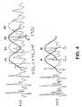
- the WSOLA methodis illustrated for an exemplary time scaling resulting in a reduction of samples of a signal in figure 4 , which comprises in the upper part an original waveform x(n) and in the lower part a synthetic waveform y(n) constructed with suitable values of the original waveform x(n).
- nindicates the respective sample of the signals.
- the WSOLA methodis based on constructing a synthetic waveform that maintains maximal local similarity to the original signal.
- the synthetic waveform y(n) and original waveform x(n)have maximal similarity around time instances specified by a time warping function ⁇ -1 (n).
- segment 41' of the input signal x(n)would overlap perfectly with segment 41 of the input signal x(n).
- Segment 41'is therefore used as a template when choosing a segment 42 around time instant ⁇ -1 (S k ) of the input signal x(n) which is to be used as next synthesis segment B.
- a similarity measure between segment 41' and segment 42is computed to find the optimal shifting value ⁇ that maximizes the similarity between the segments.
- the next synthesis segment Bis thus selected by finding the best match 42 for the template 41' around time instant ⁇ -1 (S k ).
- the best matchmust be within the tolerance interval of ⁇ , which tolerance interval lies between a predetermined minimum ⁇ min and a predetermined maximum ⁇ max value.
- segment 42' of the input signal x(n)is used as the next template.
- the same methodcan be employed not only for reducing the samples of a signal but also for increasing the amount of samples of a signal.
- the pitch periodshould not change during the jumps from the signal used as received to the time scaled signal.
- WSOLA time scalingpreserves the pitch period.
- some discontinuity on either the beginning, or the end of the time scaled signalcan not be avoided sometimes.
- the modified WSOLA (MWSOLA) methoduses history information and extra extension to decrease the effect of this problem.
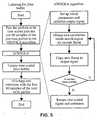
- a MWSOLA algorithm using an extension of the time scale for an extra half of a packet lengthwill now be described with reference to the flow chart of figure 5 and to the five diagrams of figure 6 .
- the used packet sizeis 20 ms, or 160 samples, the sampling rate being 8 kHz.
- the analysis/ synthesis window usedhas the same length as the packets.
- Figure 5illustrates the basic process of updating the jitter buffer size using the proposed MWSOLA algorithm.
- the packets to be time scaledare chosen.
- 1/2 packet length of the previously arrived signali.e. 80 samples, are selected as history samples.
- the selected samplesare also indicated in the first diagram of figure 6 . After being selected, they are forwarded to the MWSOLA algorithm.
- the MWSOLA algorithmwhich is shown in more detail on the right hand side of figure 5 , is then used to provide the desired time scaling on the selected signals as described with reference to figure 4 .
- the analysis/synthesis windowis created by modifying a Hanning window so that the condition of equation (1) is fulfilled.
- the time warping function ⁇ -1 (n)is constructed differently for time scale expansion and compression, i.e. for an increase and for a decrease of the jitter buffer size.
- the first frame from the input signalis copied to an output signal which is to substitute the original signal. This ensures that the change from the preceding original signal to the time scaled signal is smooth.
- a loopis used to find new frames for the time scaled output signal as long as needed.
- a best match between the last L samples of the previous frame and the first L samples of the new frameis used as an indicator in finding the next frame.
- the second diagram of figure 6shows how the analysis windows 61-67 defining different segments are placed in the MWSOLA input signal when time scaling two packets to three packets.
- the third diagram of figure 6shows how overlapping the synthesis segments succeeded. As can be seen, the different windows 61-67 overlap, in this case, quite nicely.
- the jitter bufferis then updated with the time scaled signals and the extension is overlap added with the next arriving packet.
- the resulting signalcan be seen in the fifth diagram of figure 6 .
- phase vocoder based jitter buffer scaling methodwill now be described with reference to figures 7 to 9 as third approach. This method constitutes a frequency domain time scaling method.
- the phase vocoder time scale modification methodis based on taking short-time Fourier transforms (STFT) of the speech signal in the jitter buffer as described in the above mentioned document "Applications of Digital Signal Processing to Audio and Acoustics".
- STFTshort-time Fourier transforms
- Figure 7illustrates this technique.
- the phase vocoder based time scale modificationcomprises an analyzing stage, indicated in the upper part of figure 7 , a phase modification stage indicated in the middle of figure 7 , and a synthesis stage indicated in the lower part of figure 7 .
- short-time Fourier transformsare taken from overlapping windowed parts 71-74 of a received signal.
- DFTdiscrete time Fourier transforms
- R ais called the analysis hop factor.
- the vocoder channelscan also be called bins.
- Nis the size of the DFT, where N must be longer than the length of the analysis window. In practical solutions, the DFT is usually obtained with the Fast Fourier Transform (FFT).
- FFTFast Fourier Transform
- the analysis window's cutoff frequency for the standard (Hanning, Hamming) windowsrequires the analysis windows to overlap by at least 75%. After the analysis FFT, the signal is represented by horizontal vocoder channels and vertical analysis time instants.
- the time scale of the speech signalis modified by setting the analysis hop factor R a different from a to be used synthesis hop factor R s , as described in the mentioned document "Improved Phase Vocoder Time-Scale Modification of Audio".
- the new time-evolution of the sine wavesis achieved by setting ⁇ k )
- X t a u ⁇ ⁇ k and by calculating new phase values for Y t s u ⁇ ⁇ k .
- phase unwrappingis used, where the phase increment between two consecutive frames is used to estimate the instantaneous frequency of a nearby sinusoid in each channel k.
- the instantaneous frequencyis determined because the FFT is calculated only for discrete frequencies ⁇ k . Thus the FFT does not necessarily represent the windowed signal exactly.
- the signalcan be reconstructed in a synthesis stage.
- the distance between the analysis windowsis different from the distance between the synthesis windows due to the time scale modification, therefore a time extension or compression of the received jitter buffer data is achieved.
- Synchronisation between overlapping synthesis windowswas achieved by modifying the phases in the STFT.
- phase vocoder based time scalingfor increasing or decreasing the size of a jitter buffer is illustrated in the flow chart of figure 8 .
- the input signalis received and a time scaling factor is set.
- the algorithmis then initialized by setting analysis and synthesis hop sizes, and by setting the analysis and synthesis time instants.
- the cutoff frequency of the analysis windowmust satisfy w h ⁇ min i ⁇ w i , i.e. the cutoff frequency must be less than the spacing between two sinusoids.
- the length of the analysis windowmust be small enough so that the amplitudes and instantaneous frequencies of the sinusoids can be considered constants inside the analysis window.
- the cutoff frequency and the analysis ratemust satisfy w h Ra ⁇ ⁇ .
- the cutoff frequency for standard analysis windowsis W h ⁇ 4 ⁇ /Nw, where Nw is the length of the analysis window.
- initial parameterthe number of frames to process is calculated. This number is used to determine how many times the following loop in figure 8 must be processed. Finally, initial synthesis phases are set, according to equation (7).
- a vocoder processing loopfollows for the actual time scaling.
- the routineis a straightforward realization of the method presented above.
- the respective next analysis frameis obtained by multiplying the signal with the analysis window at time instant t a u
- the FFT of the frameis calculated.
- the heterodyned phase incrementis calculated by setting R a in equation (4) to t a u - t a u - 1 .
- Instantaneous frequenciesare also obtained by setting R a in equation (5) to t a u - t a u - 1 .
- the time scaled phasesare obtained from equation (6).
- the IFFT of the modified FFT of the current frameis calculated according to equation (8).
- the result of equation (8)is then multiplied by the synthesis window and added to the output signal.
- the previous analysis and synthesis phases to be used in equations (4) and (6)are updated.
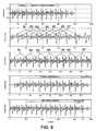
- Figure 9shows the resulting signal when time scaling two packets into three with the phase vocoder based time scaling.
- a first diagram of figure 9the amplitude of the signal over the samples before time scaling is depicted.
- a second diagram of figure 9the amplitude of the signal over the samples after time scaling is depicted.
- the two packets with samples 161 to 481 in the first diagramwere expanded to three packets with samples 161 to 641.
- an error concealmentshould be performed before the jitter buffer size is increased. Moreover, a predetermined number of packets should be received before the jitter buffer size is increased.
- Figure 10is a flow chart illustrating a fourth approach, which can be used for changing a jitter buffer size in the parametric domain.
- the parametric coded speech framesare only decoded by a decoder after buffering in the jitter buffer.
- a first stepit is determined whether the jitter buffer size has to be changed. In case it does not have to be changed, the contents of the jitter buffer are directly forwarded to the decoder.
- the jitter bufferis increased and additional frames are generated by interpolating an additional frame from two adjacent frames in the parametric domain.
- the additional framesare used for filling the empty buffer space resulting from an increase in size. Only then the buffered frames are forwarded to the decoder.
- the jitter bufferis decreased and two adjacent or spaced apart frames are interpolated in the parametric domain into one frame.
- the distance of the two frames used for interpolation to each otherdepends on the amount of the required decrease of the jitter buffer size. Only then the buffered frames are forwarded to the decoder.
- FIG. 11 to 13shows parts of three different voice over IP communications systems.
- an encoder 111 and packetization means 112belong to a transmitting end of the system.
- the transmitting endis connected to a receiving end via a voice over IP network 113.
- the receiving endcomprises a frame memory 114, which is connected via a decoder 115 to an adaptive jitter buffer 116.
- the adaptive jitter buffer 116further has a control input connected to control means and an output to some processing means of the receiving end which are not depicted.
- Speech that is to be transmittedis encoded in the encoder 111 and packetized by the packetization means 112.
- Each packetis provided with information about its correct position in a packet stream and about the correct distance in time to the other packets.
- the resulting packetsare sent over the voice over IP network 113 to the receiving end.
- the received packetsare first reordered in the frame memory 114 in order to bring them again into the original order in which they were transmitted by the transmitting end.
- the reordered packetsare then decoded by the decoder 115 into linear PCM speech.
- the decoder 115also performs a bad frame handling on the decoded data.
- the linear PCM speech packetsare forwarded by the decoder 115 to the adaptive jitter buffer 116.
- a linear time scaling methodcan then be employed to increase or decrease the size of the jitter buffer and thereby get more time or less time for the packets to arrive to the frame memory.
- the control input of the adaptive jitter buffer 116is used for indicating to the adaptive jitter buffer 116 whether the size of the jitter buffer 116 should be changed.
- the decision on thatis taken by control means based on the evaluation of the current overall delay and the current variation of delay between the different packets.
- the control meansindicate more specifically to the adaptive jitter buffer 116 whether the size of the jitter buffer 116 is to be increased or decreased and by which amount and which packets are to be selected for time scaling.
- the adaptive jitter buffer 116time scales at least part of the presently buffered packets according to the received information, e.g. in a way described in the second or third approach.
- the jitter buffer 116is therefore extended by time scale expansion of the currently buffered speech data and reduced by time scale compression of the currently buffered speech data.
- a method based on a bad frame handling method for increasing the buffer sizecould be employed for changing the jitter buffer size. This alternative method could for example be the method of the first approach, in which moreover data is overlapped for decreasing the buffer size.
- the linear time scaling of Figure 11can be employed in particular for a low bit rate codec.
- Figure 12shows a part of a communications system which is based on a linear PCM speech time scaling method.
- a transmitting endwhich corresponds to the one in figure 11 and which is not depicted in figure 12 , is connected again via a voice over IP network 123 to the receiving end.
- the receiving endis designed somewhat differently from the receiving end in the system of figure 11 .
- the receiving endcomprises now means for A-law to linear conversion 125 connected to an adaptive jitter buffer 126.
- the adaptive jitter buffer 126has again additionally a control input connected to control means and an output to some processing means of the receiving end which are not depicted.
- Packets containing speech data which were transmitted by the transmitting end and received by the receiving end via the voice over IP network 123are first input to the means for A-law to liner conversion 125 of the receiving end, where they are converted to linear PCM data. Subsequently, the packets are reorganized in the adaptive jitter buffer 126. Moreover, the adaptive jitter buffer 126 takes care of a bad frame handling, before forwarding the packets with a correct delay to the processing means.
- Control meansare used again for deciding when and how to change the jitter buffer size. Whenever necessary, some time scaling method for linear speech, e.g. one of the presented methods, is then used in the adaptive jitter buffer 126 to change its size according to the information received by the control means. Alternatively, a method based on a bad frame handling method could be employed again for changing the jitter buffer, e.g. the method of the first approach. This alternative method could also make use of the bad frame handling method implemented in the jitter buffer anyhow for bad frame handling.
- Figure 13shows a part of a communications system in which a low bit rate codec and a parametric domain time scaling is employed.
- a transmitting endcorresponding to the one in figure 11 and not being depicted in figure 13 , is connected via a voice over IP network 133 to a receiving end.
- the receiving endcomprises a packet memory and organizer unit 134, which is connected via an adaptive jitter buffer 136 to a decoder 135.
- the adaptive jitter buffer 136further has a control input connected to control means, and the output of the decoder 135 is connected to some processing means of the receiving end, both, control means and processing means not being depicted.
- Packets containing speech data which were transmitted by the transmitting end and received by the receiving end via the voice over IP network 133are first reordered in the packet memory and organizer unit 134.
- the reordered packetsare then forwarded directly to the adaptive jitter buffer 136.
- the jitter buffer 136applies a bad frame handling on the received packets in the parametric domain.
- the speech contained in the packetsis decoded only after leaving the adaptive jitter buffer 136 in the decoder 135.
- the control meansare used for deciding when and how to change the jitter buffer size. Whenever necessary, some time scaling method for parametric speech is then used in the adaptive jitter buffer 136 to change its size according to the information received by the control means.
- a bad frame handling method designed for bad frame handling of packets in the parametric domaincould be employed for increasing the jitter buffer size.
- additional framescould be interpolated from two adjacent frames as proposed with reference to figure 10 . Decreasing the jitter buffer size could be achieved by discarding a packet or by interpolating two packets into one in the parametric domain as proposed with reference to figure 10 . In particular, if a decrease by more than one packet is desired, the packets around the desired amount of packets could be interpolated into one packet.
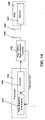
- FIG. 14shows a GSM or 3G radio communications system.
- the radio communications systemcomprises a mobile station 140, of which an antenna 141 and a decoder 142 are depicted.
- a radio access networkof which a base station and a radio network controller 143 is depicted as a single block with access to an antenna 144.
- Base station and radio network controller 143are further connected to a network transcoder 145 comprising an encoder 146 and time alignment means 147 connected to each other.
- Base station or radio network controller 143have moreover a controlling access to the time alignment means 147.
- speech framesare transmitted in the downlink direction from the radio access network to the mobile station 140 and in the downlink direction from the mobile station 140 to the radio access network.
- Speech frames that are to be transmitted in the downlink directionare first encoded by the encoder 146 of the transcoder 145, transmitted via the radio network controller, the base station 143 and the antenna 144 of the radio access network, received by the antenna 142 of the mobile station 140 and decoded by the decoder 141 of the mobile station 140.
- the initial phase shift between uplink and downlink framing in the transcodermay be different from the phase shift of the radio interface, which prevents the required strict synchronous transmissions in uplink and downlink.
- the base station 143therefore guarantees that the phase shift is equal by buffering all encoded speech frames received from the transcoder 145 for a downlink transmission as long as required. Even though the base station 143 determines the required buffering delay by comparing uplink speech data received from the mobile station 140 with downlink speech data received from the transcoder 145, this means also a compensation of a phase shift of the downlink framing in the transcoder and at radio interface of the system accessed via the antenna 144.
- this functionis provided by the radio network controller 143.
- This bufferingleads to an additional delay of up to one speech frame in the base station in downlink direction.
- the radio network controller 143requests from the time alignment means 147 of the transcoder 145 to apply a time alignment to the encoded speech frames.
- the transmission time instant of an encoded speech frame and the following framesis advanced or delayed for a specified amount of samples according to the information received the base station or the radio network controller 143 respectively, thus reducing the necessary buffering delay in the base station or the radio network controller 143.
- the time alignmentis now carried out by the time alignment means 147 by applying a time scaling on the speech frames encoded by the encoder 146, before forwarding them to the radio network controller or the base station 143.
- a time scalingon the speech frames encoded by the encoder 146, before forwarding them to the radio network controller or the base station 143.
- any of the time domain or frequency domain time scaling methods proposed for changing a jitter buffer sizecan be employed.
- the buffering delay in the base station 143is reduced as in a known time alignment, but the speech quality is affected less.
Landscapes
- Engineering & Computer Science (AREA)
- Signal Processing (AREA)
- Multimedia (AREA)
- Health & Medical Sciences (AREA)
- Audiology, Speech & Language Pathology (AREA)
- Human Computer Interaction (AREA)
- Physics & Mathematics (AREA)
- Acoustics & Sound (AREA)
- Computational Linguistics (AREA)
- Computer Networks & Wireless Communication (AREA)
- Quality & Reliability (AREA)
- Computer Hardware Design (AREA)
- Data Exchanges In Wide-Area Networks (AREA)
- Communication Control (AREA)
- Mobile Radio Communication Systems (AREA)
Abstract
Description
- The invention relates to a method for carrying out a time alignment in a transcoder of a radio communications system, which time alignment is used for decreasing a buffering delay , said buffering delay resulting from buffering speech data encoded by said transcoder before transmitting said speech data over a radio interface of said radio communications system in order to compensate for a phase shift in a framing of said speech data in said transcoder and at said radio interface. Further, the invention relates to such a radio communications system and to a transcoder for a radio communications system and to an apparatus.
- An example of a packet network is a voice over IP (VoIP) network.
- IP telephony or voice over IP (VoIP) enables users to transmit audio signals like voice over the Internet Protocol. Sending voice over the internet is done by inserting speech samples or compressed speech into packets. The packets are then routed independently from each other to their destination according to the IP-address included in each packet.
- One drawback in IP telephony is the availability and performance of networks. Although the local networks might be stable and predictable, the Internet is often congested and there are no guarantees that packets are not lost or significantly delayed. Lost packets and long delays have an immediate effect on speech quality, reciprocity and the pace of conversation.
- Because of the independent routing of the packets, the packets moreover take variable times to go through the network. The variation in packet arrival times is called jitter. To play out the voice in the receiving end correctly, though, the packets must be in the order of transmission and equally spaced. To achieve this requirement a jitter buffer can be employed. The jitter buffer can be located before or after a decoder used at the receiving end for decoding the speech which was encoded for transmission. In the jitter buffer, the right order of packets can then be assured by checking sequence numbers contained in the packets. Equally contained timestamps can further be used to determine the jitter level in the network and for compensating for the jitter in play out.
- The size of the jitter buffer, however, has a contrary effect on the number of packets that are lost and on the end-to-end delay. If the jitter buffer is very small, many packets are lost because they have arrived after their playout point. On the other hand, if the jitter buffer is very large an excessive end-to-end delay appears. Both, packet loss and end-to-end delay, have an effect on speech quality. Therefore, the size of the jitter buffer has to result in an acceptable value for both, packet loss and delay. Since both can vary in time, adaptive jitter buffers have to be employed in order to be able to continuously guarantee a good compromise for the two factors. The size of an adaptive jitter buffer can be changed based on measured delays of received speech packets and measured delay variances between received speech packets.
- Known methods adjust the jitter buffer size in the beginning of a talkspurt. At the beginning of a talkspurt and therefore at the end of a pause in speech, the played out speech is not affected by the adjustment of the jitter buffer size. This means, however, that an adjustment has to be delayed until a beginning of a talkspurt occurs and that a voice activity detector (VAD) is needed. Such methods are described e.g. in "An algorithm for playout of packet voice based on adaptive adjustment of talkspurt silence periods", LCN '99, Conference on Local Computer Networks, 1999, Pages 224 - 231, by J. Pinto and K.J. Christensen, and in "Adaptive playout mechanisms for packetized audio applications in wide-area networks", INFOCOM '94, 13th Proceedings IEEE Networking for Global Communications, 1994, Pages 680 - 688, vol.2, by R. Ramjee, J. Kurose, D. Towsley and H. Schulzrinne.
- A similar problem with jitter buffers can arise e.g. in voice over ATM networks.
- A similar problem can moreover arise during time alignment in GSM (global system for mobile communications) or 3G (third generation) systems. In radio communications systems like GSM or a 3G system, the air interface requires a tight synchronization between uplink and downlink transmission. However, at the start of call or after a handover, the initial phase shift between uplink and downlink framing in a transcoder used on the network side for encoding data for downlink transmissions and decoding data from uplink transmissions is different from the corresponding phase shift at the radio interface. This phase shift can also be seen in the phase shift only of the downlink framing in the transcoder and at a radio interface of the radio communications system. Therefore, a downlink buffering is needed to achieve a correct synchronization for the air interface, which buffer is included in GSM in a base station and in 3G networks in a radio network controller (RNC) of the communications system. The buffering leads to an additional delay of up to one speech frame in the base station in downlink direction. To minimize this buffering delay, a time alignment procedure can be utilized on the network side. The time alignment is used to align the phase shift in the framing of the transcoder and thus to minimizing the buffering delay after a call set-up or handover. During the time alignment, the base station or radio network controller requests the transcoder to carry out a desired time alignment. In the time alignment, the transmission time instant of an encoded speech frame and the following frames need to be advanced or delayed. Thereby the window (one speech frame) of input buffer of linear samples before the encoder has to be slided in to the desired direction by the amount of samples requested by the base station. Presently, a time alignment is carried out by dropping or repeating speech samples, which leads to a deterioration of the speech quality.
US patent 5,664,044 aims at providing a system and method for allowing user-controlled, variable-speed synchronized playback of an existing, digitally-recorded audio/video presentation. The digital data stream is a multiplexed, compressed audio/video data stream such as that specified in the MPEG standard. In one embodiment, the user directly controls the rate of the video playback by setting a video scaling factor. The length of time required to play back an audio frame is then adjusted automatically using the time domain harmonic scaling method so that it approximately matches the length of time a video frame is displayed. The number of frames of compressed digital audio in an audio buffer is monitored and the time domain harmonic scaling factor is adjusted continuously during playback to ensure that the audio buffer does not overflow or underflow. An underflow or overflow condition in the audio buffer would eventually cause a loss of synchronization between the audio and video.- It is an object of the invention to improve the time alignment in radio communications systems.
- This object is reached on the one hand with a method for carrying out a time alignment in a transcoder of a radio communications system, which time alignment is used for decreasing a buffering delay, said buffering delay resulting from buffering speech data encoded by said transcoder before transmitting said speech data over a radio interface of said radio communications system in order to compensate for a phase shift in a framing of said speech data by said transcoder and by said radio interface. First, it is determined whether a time alignment has to be carried out.
- In case it was determined that a time alignment has to be carried out, speech data is condensed for achieving the required time alignment by discarding at least one frame of speech data. Gain parameters and Linear Predictive Coding (LPC) coefficients of frames of speech data surrounding the at least one discarded frame are moreover modified to smoothly combine the frames surrounding the at least one discarded frame.
- The object of the invention is reached on the other hand with a radio communications system comprising at least one radio interface for transmitting encoded speech data and at least one transcoder. Said transcoder includes at least one encoder for encoding speech data to be used for a transmission via said radio interface. The transcoder further includes processing means for carrying out a time alignment on encoded speech samples according to the proposed method. The radio communications system moreover comprises buffering means arranged between said radio interface and said transcoder for buffering speech data encoded by said transcoder before transmitting said encoded speech data via said radio interface in order to compensate for a phase shift in a framing of said speech data by said transcoder and by said radio interface. Finally, the radio communications system comprises processing means for determining whether and to which extend the speech samples encoded by said encoder have to be time aligned before transmission in order to minimize a buffering delay for encoded speech data resulting from a buffering by said buffering means. The object of the invention is equally reached with such a transcoder for a radio communications system.
- The invention proceeds from the idea that the time alignment in a transcoder of a radio communications system could be achieved with less effect on the encoded speech samples, if it is not carried out by simply dropping or repeating speech samples, but rather by compensating for the time alignment in a more sophisticated way that results in less effect on the quality of the speech data. The proposed compensation of a time alignment ensures only smooth transitions within the aligned speech data. It is thus an advantage of the invention that it enables in a simple way an improved time alignment.
- It is to be noted that strictly speaking the mentioned phase shift relates to the time difference of sending and receiving the first data bit of a frame on uplink vs. downlink, i.e. how data frames aligned in time at an observation point in different transmission directions. For GSM, e.g., initially this time difference is not equal between air and abis interfaces. After the time alignment, the time difference should be almost equal, i.e. minimal buffering.
- It becomes apparent that the invention is based on changing the amount of currently available audio data based on this existing audio data such that a necessary change can be achieved without severe deterioration of the audio data during ongoing transmission.
- The invention can be employed in particular, though not exclusively, in a Media Gateway as well as in GSM and 3G time alignments.
- In the following, the invention is explained in more detail with reference to drawings, of which
- Fig. 1
- illustrates the principle of three approaches for changing the jitter buffer size;
- Fig. 2
- shows diagrams illustrating an increase in jitter buffer size according to the first approach based on a method for bad frame handling;
- Fig. 3
- shows diagrams illustrating a decrease in jitter buffer size according to the first approach ;
- Fig. 4
- shows diagrams illustrating the principle of a time domain time scaling according to a secondapproach;
- Fig. 5
- is a flow chart of the second approach;
- Fig. 6
- shows diagrams further illustrating the second approach;
- Fig. 7
- shows diagrams illustrating the principle of a third approachfrequency domain time scaling;
- Fig. 8
- is a flow chart of the third approach;
- Fig. 9
- shows jitter buffer signals before and after time scaling according to the third approach;
- Fig. 10
- is a flow chart illustrating a fourth approach changing a jitter buffer size in the parametric domain;
- Fig. 11
- schematically shows a part of a first system;
- Fig. 12
- schematically shows a part of a second system; and
- Fig. 13
- schematically shows a part of a third system; and
- Fig. 14
- schematically shows a communications system in which a time alignment according to the invention can be employed.
- On the left hand side of the
figure 1 , an increase of a packet stream is shown, while on the left hand side, a decrease of a packet stream is shown. The upper part of the figure shows for both cases original streams, the middle part for both cases streams treated according to a first approach and the lower part for both cases streams treated according to a second or third approach. - In the upper left part of
figure 1 , a first packet stream with eightoriginal packets 1 to 8 including speech data is indicated. This packet stream is contained in a jitter buffer of a receiving end in a voice over IP network before an increase of the jitter buffer size becomes necessary. In the upper right part offigure 1 , a second packet stream with ninepackets 9 to 17 including speech data is indicated. This packet streams is contained in a jitter buffer of a receiving end in a voice over IP network before a decrease of the jitter buffer size becomes necessary. - On the left hand side in the middle of
figure 1 , the first packet stream is shown after an increase of the jitter buffer size. The jitter buffer size was increased by providing an empty space of the length of one packet between theoriginal packet 4 and theoriginal packet 5 of the packet stream in the jitter buffer. This empty space is filled by apacket 18 generated according to a bad frame handling BFH as defined in the above mentioned ITU-T G.711 codec, the empty space simply being considered as lost packet. The size of the original stream is thus expanded by the length of one packet. - On the right hand side in the middle of
figure 1 , in contrast, the second packet stream is shown after a decrease of the jitter buffer size. It is realized in the first described approach by overlapping two consecutive packets, in this example, theoriginal packet 12 and theoriginal packet 13 of the second packet stream. The overlapping reduces the number of speech samples contained in the jitter buffer in the length of one packet, the size of which can thus be reduced by the length of one packet. - On the left hand side at the bottom of
figure 1 , the first packet stream is shown again after an increase of the jitter buffer size which resulted in an empty space of the length of one packet between theoriginal packets original packets original packets - On the right hand side at the bottom of
figure 1 , finally, the second packet stream is shown again after a decrease of the jitter buffer size. The corresponding decrease of the data stream was realized according to the second or third approach by time scaling the data of three original packets to the length of two packets. In the presented example, the data of theoriginal packets 12 to 14 of the second packet stream were condensed to the length of two packets. The size of the original stream was thus reduced by the length of one packet. - The increase and decrease of the jitter buffer size according to the first approach will now be explained in detail with reference to
figures 2 and3 . Figure 2 is taken from the ITU-T G.711 Appendix specification, where it is used for illustrating lost packet concealment, while here it is used for illustrating the first approach , in which the ITU-T bad frame handler is called between adjacent packets for compensating for an increase of the jitter buffer size.Figure 2 shows three diagrams which depict the amplitude of signals over the sample number of the signals. In the first diagram the signals input to the jitter buffer are shown, while a second and third diagram show synthesized speech at two different points in time. The diagrams illustrate how the jitter buffer size is increased according to the first approach corresponding to a bad frame handling presented in the above cited ITU-T G.711 codec. As mentioned above, the cited standard describes a packet loss concealment method for the ITU-T G.711 codec based on pitch waveform replication.- The packet size employed in this approach is 20ms, which corresponds to 160 samples. The BFH was modified to be able to use 20 ms packets.
- The arrived packets as well as the synthesised packets are saved in a history buffer of a length of 390 samples.
- After an increase of the size of the jitter buffer by the length of two packets, there is an empty space in the jitter buffer corresponding to two lost packets, indicated in the first diagram of
figure 2 by a horizontal line connecting the received signals. At the start of each empty space, the contents of the history buffer are copied to a pitch buffer that is used throughout the empty space to find a synthetic waveform that can conceal the empty space. In the situation in the first diagram, the samples that are to the left of the two empty packets i.e. the samples that have arrived before the increase of size, form the current content of the pitch buffer. - A cross-correlation method is now used to calculate a pitch period estimate from the pitch buffer. As illustrated in the second diagram of
figure 2 , the first empty packet is then replaced by replicating the waveform that starts one pitch period length back from the end of the history buffer, indicated with a vertical line referred to by 21, in the required number. To ensure a smooth transition between the real and the synthesized speech, as well as between repeated pitch period length waveforms, the last 30 samples in the history buffer, in the region limited by a vertical and an inclined line referred to by 22 in the first diagram, are overlap added with the 30 samples preceding the synthetic waveform in the region limited by thevertical line 21 and a connected inclined line. The overlapped signal replaces the last 30samples 22 in the pitch buffer. This overlap add procedure causes an algorithmic delay of 3.75 ms, or 30 samples. In the same way, a smooth transition between repeated pitch period length waveforms is ensured. - The synthetic waveform is moreover extended beyond the duration of the empty packets to ensure a smooth transition between the synthetic waveform and the subsequently received signal. The length of the extension 23 is 4 ms. In the end of the empty space, the extension is raised by 4 ms per additional added empty packet. The maximum extension length is 10 ms. In the end of the empty space this extension is overlapped with the signal of the first packet after the empty space, the overlap region being indicated in the figure with the
inclined line 25. The second diagram offigure 2 illustrates the state of the synthesized signal after 10 ms, when samples of one packet length have been replicated. - In case there is a second added empty packet, as in the first diagram of
figure 2 , another pitch period is added to the pitch buffer. Now the waveform to be replicated is two pitch periods long and starts from the vertical line referred to by 24. Next, the 30samples 24 before the pitch buffer are overlap added with the last 30samples 22 in the pitch buffer. Again, the overlapped signal replaces the last 30 samples inregion 22 in the pitch buffer. A smooth transition between one and two pitch period length signals is ensured by performing an overlap add between the regions indicated by 23 and 26.Region 26 is placed by subtracting pitch periods until the pitch pointer is in the first wavelength of the currently used portion of the pitch buffer. The result of the overlap adding replaces the samples in region 23. The third diagram offigure 2 shows the synthesized signal in which an empty space of the length of two packets added for an increase in the size of the jitter buffer was concealed. - If the size of the jitter buffer is further increased, another pitch period would be added to the pitch buffer. However, if the increase in jitter buffer size is large it is more likely that the replacement signal falsifies the original signal. Attenuation is used to diminish this problem. The first replacement packet is not attenuated. The second packet is attenuated with a linear ramp. The end of the packet is attenuated by 50 % compared to the start with the used packet size of 20 ms. This attenuation is also used for the following packets. This means that after 3 packets (60 ms) signal amplitude is zero.
- Similarly, parametric speech coders' bad frame handling methods can be employed for compensating for an increase of the jitter buffer size.
Figure 3 illustrates how the jitter buffer size is decreased according to the first approach by overlapping two adjacent packets. To this end, the figure shows three diagrams depicting the amplitude of signals over the sample number of the signals.- The first diagram of
figure 3 shows the signals of four packets 31-34 presently stored in a jitter buffer before a decrease in size, each packet containing 160 samples. Now, the size of the jitter buffer is to be decreased by one packet. To this end, twoadjacent packets downramp 36 and anupramp 37 function respectively, as indicated in the first diagram. Then, the multipliedpackets figure 3 . Finally, the overlapped part of thesignal 32/33 is added as shown in the third diagram offigure 3 , the fourth packet now being formed by thepacket 35 following the originalfourth packet 34. The result of the overlap adding is a signal comprising one packet less than the original signal, and this removed packet enables a decrease of the size of the jitter buffer. - When the jitter buffer size is to be decreased by more than one packet at a time, not adjacent but spaced apart packets are overlap added, and the packets in between are discarded. For example, if the jitter buffer size is to be changed from three packets to one, the first packet in the jitter buffer is overlap added with the third packet in the jitter buffer as described for
packets figure 3 , and the second packet is discard. - In a second approach, an immediate increase and decrease of a jitter buffer size is enabled by a time domain time scaling method, and more particularly by a waveform similarity overlap add (WSOLA) method described in the above mentioned document "An overlap-add technique based on waveform similarity (WSOLA) for high quality time-scale modification of speech".
- The WSOLA method is illustrated for an exemplary time scaling resulting in a reduction of samples of a signal in
figure 4 , which comprises in the upper part an original waveform x(n) and in the lower part a synthetic waveform y(n) constructed with suitable values of the original waveform x(n). n indicates the respective sample of the signals. The WSOLA method is based on constructing a synthetic waveform that maintains maximal local similarity to the original signal. The synthetic waveform y(n) and original waveform x(n) have maximal similarity around time instances specified by a time warping function τ-1(n). - In
figure 4 , theinput segment 41 of original waveform x(n) was the last segment excised from the original waveform x(n). Thissegment 41 is the last segment that was added as a synthesis segment A to the synthesized waveform y(n). Segment A was overlap-added to the output signal y(n) at time Sk-1=(k-1)S, S being the interval between segments in the synthesized signal y(n). - The next synthesis segment B is to be excised from the input signal x(n) around time instant τ-1(Sk), and overlap added to the output signal y(n) at time Sk=kS. As can be seen in the figure, segment 41' of the input signal x(n) would overlap perfectly with
segment 41 of the input signal x(n). Segment 41' is therefore used as a template when choosing asegment 42 around time instant τ-1(Sk) of the input signal x(n) which is to be used as next synthesis segment B. A similarity measure between segment 41' andsegment 42 is computed to find the optimal shifting value Δ that maximizes the similarity between the segments. The next synthesis segment B is thus selected by finding thebest match 42 for the template 41' around time instant τ-1(Sk). The best match must be within the tolerance interval of Δ, which tolerance interval lies between a predetermined minimum Δmin and a predetermined maximum Δmax value. After overlap-adding thesynthesis segment 42 to the output signal as segment B, segment 42' of the input signal x(n) is used as the next template. - The WSOLA method uses regularly spaced synthesis instants Sk=kS. The analysis and synthesis window length is constant. If the analysis/synthesis window is chosen in such a way that,


- By selecting a different time warping function, the same method can be employed not only for reducing the samples of a signal but also for increasing the amount of samples of a signal.
- It is important that the transition from the original signal to the time-scaled signal is smooth. In addition, the pitch period should not change during the jumps from the signal used as received to the time scaled signal. As was explained previously, WSOLA time scaling preserves the pitch period. However, when time scaling is performed for a part in the middle of the speech signal, some discontinuity on either the beginning, or the end of the time scaled signal can not be avoided sometimes.
- In order to decrease the effect of such a phase mismatch, it is proposed for the second approach to slightly modify the method described with reference to
figure 4 . The modified WSOLA (MWSOLA) method uses history information and extra extension to decrease the effect of this problem. - A MWSOLA algorithm using an extension of the time scale for an extra half of a packet length will now be described with reference to the flow chart of
figure 5 and to the five diagrams offigure 6 . The used packet size is 20 ms, or 160 samples, the sampling rate being 8 kHz. The analysis/ synthesis window used has the same length as the packets. Figure 5 illustrates the basic process of updating the jitter buffer size using the proposed MWSOLA algorithm. As shown on the left hand side of the flow chart offigure 5 , first the packets to be time scaled are chosen. In addition, 1/2 packet length of the previously arrived signal, i.e. 80 samples, are selected as history samples. The selected samples are also indicated in the first diagram offigure 6 . After being selected, they are forwarded to the MWSOLA algorithm.- The MWSOLA algorithm, which is shown in more detail on the right hand side of
figure 5 , is then used to provide the desired time scaling on the selected signals as described with reference tofigure 4 . - The analysis/synthesis window is created by modifying a Hanning window so that the condition of equation (1) is fulfilled. The time warping function τ-1(n) is constructed differently for time scale expansion and compression, i.e. for an increase and for a decrease of the jitter buffer size. The time warping function and the limits of the search region Δ (Δ= [Δmin...Δmax]) are chosen in such a way that a good signal variation is obtained. By setting the limits of the search region and the time warping function correctly, it can be avoided that adjacent analysis frames are chosen repeatedly. Finally, the first frame from the input signal is copied to an output signal which is to substitute the original signal. This ensures that the change from the preceding original signal to the time scaled signal is smooth.
- After the initial parameters like the time warping function and the limits for the search region are set and an output signal is initialized, a loop is used to find new frames for the time scaled output signal as long as needed. A best match between the last L samples of the previous frame and the first L samples of the new frame is used as an indicator in finding the next frame. The used length L of the correlation is 1/2 * window length = 80 samples. The search region Δ (Δ= [Δmin...Δmax]) should be longer than the maximum pitch period in samples, so that a correct synchronization between consecutive frames is possible.
- The second diagram of
figure 6 shows how the analysis windows 61-67 defining different segments are placed in the MWSOLA input signal when time scaling two packets to three packets. - The third diagram of
figure 6 shows how overlapping the synthesis segments succeeded. As can be seen, the different windows 61-67 overlap, in this case, quite nicely. - Overlap adding of all the analysis/synthesis frames results in the time scaled signal shown in the fourth diagram of
figure 6 , which constitutes the output signal of the MWSOLA algorithm. The MWSOLA algorithm returns the new time scaled packets and an extension to be overlap added with the first 1/2 packet length of the next arriving packet. - As shown again on the left hand side of the flow chart of
figure 5 , the jitter buffer is then updated with the time scaled signals and the extension is overlap added with the next arriving packet. The resulting signal can be seen in the fifth diagram offigure 6 . - This procedure decreases the effect of the phase and amplitude mismatches between the time-scaled signal and the valid signal.
- A phase vocoder based jitter buffer scaling method will now be described with reference to
figures 7 to 9 as third approach. This method constitutes a frequency domain time scaling method. - The phase vocoder time scale modification method is based on taking short-time Fourier transforms (STFT) of the speech signal in the jitter buffer as described in the above mentioned document "Applications of Digital Signal Processing to Audio and Acoustics".
Figure 7 illustrates this technique. The phase vocoder based time scale modification comprises an analyzing stage, indicated in the upper part offigure 7 , a phase modification stage indicated in the middle offigure 7 , and a synthesis stage indicated in the lower part offigure 7 . - In the analyzing stage, short-time Fourier transforms are taken from overlapping windowed parts 71-74 of a received signal. In particular, discrete time Fourier transforms (DFT) as described byJ. Laroche and M. Dolson in "Improved Phase Vocoder Time-Scale Modification of Audio", IEEE Transactions on Speech and Audio Processing, Vol. 7, No. 3, May 1999. pp. 323-332, can be employed in the phase vocoder analysis stage. This means that both, the frequency scale and the time scale representation of the signal, are discrete. The analysis time instants


- In the phase modification stage, the time scale of the speech signal is modified by setting the analysis hop factor Ra different from a to be used synthesis hop factor Rs, as described in the mentioned document "Improved Phase Vocoder Time-Scale Modification of Audio". The new time-evolution of the sine waves is achieved by setting


- The new phase values for


- Then by adding or subtracting multiples of 2π so that the result of (7) lies between ±π, the principal determination

- The instantaneous frequency is then calculated using

- The instantaneous frequency is determined because the FFT is calculated only for discrete frequencies Ωk. Thus the FFT does not necessarily represent the windowed signal exactly.
- The time scaled phases of the STFT at a timetus are calculated from

- The choice of initial synthesis phases


- After the phases values for

- In the synthesis stage, the modified short time Fourier transforms Y(tsu, Ωk ) are first inverse Fourier transformed with the equation

- The synthesis time instants are set


- The distance between the analysis windows is different from the distance between the synthesis windows due to the time scale modification, therefore a time extension or compression of the received jitter buffer data is achieved. Synchronisation between overlapping synthesis windows was achieved by modifying the phases in the STFT.
- The use of the phase vocoder based time scaling for increasing or decreasing the size of a jitter buffer is illustrated in the flow chart of
figure 8 . - First, the input signal is received and a time scaling factor is set.
- The algorithm is then initialized by setting analysis and synthesis hop sizes, and by setting the analysis and synthesis time instants. When doing this, a few constraints have to be taken into account, which have been listed e.g. in the above mentioned document "Applications of Digital Signal Processing to Audio and Acoustics". The cutoff frequency of the analysis window must satisfy wh < miniΔwi, i.e. the cutoff frequency must be less than the spacing between two sinusoids. Further, the length of the analysis window must be small enough so that the amplitudes and instantaneous frequencies of the sinusoids can be considered constants inside the analysis window. Finally, to enable phase unwrapping, the cutoff frequency and the analysis rate must satisfy whRa < π. The cutoff frequency for standard analysis windows (Hamming, Hanning) is Wh ≈ 4π/Nw, where Nw is the length of the analysis window.
- As further initial parameter, the number of frames to process is calculated. This number is used to determine how many times the following loop in
figure 8 must be processed. Finally, initial synthesis phases are set, according to equation (7). - After initialization, a vocoder processing loop follows for the actual time scaling. Inside the phase vocoder processing loop, the routine is a straightforward realization of the method presented above. First, the respective next analysis frame is obtained by multiplying the signal with the analysis window at time instant


- Finally, before outputting the time scaled signal, transitions between the time scaled and the non time scaled signal are smoothed. After this, the jitter buffer size modification can be completed.
Figure 9 shows the resulting signal when time scaling two packets into three with the phase vocoder based time scaling. In a first diagram offigure 9 , the amplitude of the signal over the samples before time scaling is depicted. In a second diagram offigure 9 , the amplitude of the signal over the samples after time scaling is depicted. The two packets withsamples 161 to 481 in the first diagram were expanded to three packets withsamples 161 to 641. - Before the jitter buffer size is increased, an error concealment should be performed. Moreover, a predetermined number of packets should be received before the jitter buffer size is increased.
Figure 10 is a flow chart illustrating a fourth approach, which can be used for changing a jitter buffer size in the parametric domain. The parametric coded speech frames are only decoded by a decoder after buffering in the jitter buffer.- In a first step, it is determined whether the jitter buffer size has to be changed. In case it does not have to be changed, the contents of the jitter buffer are directly forwarded to the decoder.
- In case it is determined that the jitter buffer size has to be increased, the jitter buffer is increased and additional frames are generated by interpolating an additional frame from two adjacent frames in the parametric domain. The additional frames are used for filling the empty buffer space resulting from an increase in size. Only then the buffered frames are forwarded to the decoder.
- In case it is determined that the jitter buffer size has to be decreased, the jitter buffer is decreased and two adjacent or spaced apart frames are interpolated in the parametric domain into one frame. The distance of the two frames used for interpolation to each other depends on the amount of the required decrease of the jitter buffer size. Only then the buffered frames are forwarded to the decoder.
Figures 11 to 13 shows parts of three different voice over IP communications systems.- In the communications system of
Figure 11 , anencoder 111 and packetization means 112 belong to a transmitting end of the system. The transmitting end is connected to a receiving end via a voice overIP network 113. The receiving end comprises aframe memory 114, which is connected via adecoder 115 to anadaptive jitter buffer 116. Theadaptive jitter buffer 116 further has a control input connected to control means and an output to some processing means of the receiving end which are not depicted. - At the transmitting end, speech that is to be transmitted is encoded in the
encoder 111 and packetized by the packetization means 112. Each packet is provided with information about its correct position in a packet stream and about the correct distance in time to the other packets. The resulting packets are sent over the voice overIP network 113 to the receiving end. - At the receiving end, the received packets are first reordered in the
frame memory 114 in order to bring them again into the original order in which they were transmitted by the transmitting end. The reordered packets are then decoded by thedecoder 115 into linear PCM speech. Thedecoder 115 also performs a bad frame handling on the decoded data. After this, the linear PCM speech packets are forwarded by thedecoder 115 to theadaptive jitter buffer 116. In the adaptive jitter buffer, a linear time scaling method can then be employed to increase or decrease the size of the jitter buffer and thereby get more time or less time for the packets to arrive to the frame memory. - The control input of the
adaptive jitter buffer 116 is used for indicating to theadaptive jitter buffer 116 whether the size of thejitter buffer 116 should be changed. The decision on that is taken by control means based on the evaluation of the current overall delay and the current variation of delay between the different packets. The control means indicate more specifically to theadaptive jitter buffer 116 whether the size of thejitter buffer 116 is to be increased or decreased and by which amount and which packets are to be selected for time scaling. - In case the control means indicate to the
adaptive jitter buffer 116 that its size is to be changed, theadaptive jitter buffer 116 time scales at least part of the presently buffered packets according to the received information, e.g. in a way described in the second or third approach. Thejitter buffer 116 is therefore extended by time scale expansion of the currently buffered speech data and reduced by time scale compression of the currently buffered speech data. Alternatively, a method based on a bad frame handling method for increasing the buffer size could be employed for changing the jitter buffer size. This alternative method could for example be the method of the first approach, in which moreover data is overlapped for decreasing the buffer size. - The linear time scaling of
Figure 11 can be employed in particular for a low bit rate codec. Figure 12 shows a part of a communications system which is based on a linear PCM speech time scaling method. In this system, a transmitting end which corresponds to the one infigure 11 and which is not depicted infigure 12 , is connected again via a voice overIP network 123 to the receiving end. The receiving end, however, is designed somewhat differently from the receiving end in the system offigure 11 . The receiving end comprises now means for A-law tolinear conversion 125 connected to anadaptive jitter buffer 126. Theadaptive jitter buffer 126 has again additionally a control input connected to control means and an output to some processing means of the receiving end which are not depicted.- Packets containing speech data which were transmitted by the transmitting end and received by the receiving end via the voice over
IP network 123 are first input to the means for A-law toliner conversion 125 of the receiving end, where they are converted to linear PCM data. Subsequently, the packets are reorganized in theadaptive jitter buffer 126. Moreover, theadaptive jitter buffer 126 takes care of a bad frame handling, before forwarding the packets with a correct delay to the processing means. - Control means are used again for deciding when and how to change the jitter buffer size. Whenever necessary, some time scaling method for linear speech, e.g. one of the presented methods, is then used in the
adaptive jitter buffer 126 to change its size according to the information received by the control means. Alternatively, a method based on a bad frame handling method could be employed again for changing the jitter buffer, e.g. the method of the first approach. This alternative method could also make use of the bad frame handling method implemented in the jitter buffer anyhow for bad frame handling. Figure 13 , finally, shows a part of a communications system in which a low bit rate codec and a parametric domain time scaling is employed.- Again, a transmitting end corresponding to the one in
figure 11 and not being depicted infigure 13 , is connected via a voice overIP network 133 to a receiving end. The receiving end comprises a packet memory andorganizer unit 134, which is connected via anadaptive jitter buffer 136 to adecoder 135. Theadaptive jitter buffer 136 further has a control input connected to control means, and the output of thedecoder 135 is connected to some processing means of the receiving end, both, control means and processing means not being depicted. - Packets containing speech data which were transmitted by the transmitting end and received by the receiving end via the voice over
IP network 133 are first reordered in the packet memory andorganizer unit 134. - The reordered packets are then forwarded directly to the
adaptive jitter buffer 136. Thejitter buffer 136 applies a bad frame handling on the received packets in the parametric domain. The speech contained in the packets is decoded only after leaving theadaptive jitter buffer 136 in thedecoder 135. - As in the other two presented systems, the control means are used for deciding when and how to change the jitter buffer size. Whenever necessary, some time scaling method for parametric speech is then used in the
adaptive jitter buffer 136 to change its size according to the information received by the control means. Alternatively, also a bad frame handling method designed for bad frame handling of packets in the parametric domain could be employed for increasing the jitter buffer size. As further alternative, additional frames could be interpolated from two adjacent frames as proposed with reference tofigure 10 . Decreasing the jitter buffer size could be achieved by discarding a packet or by interpolating two packets into one in the parametric domain as proposed with reference tofigure 10 . In particular, if a decrease by more than one packet is desired, the packets around the desired amount of packets could be interpolated into one packet. - An embodiment of the invention relating to time alignment will now be presented with reference to
figure 14 , which shows a GSM or 3G radio communications system. - The radio communications system comprises a
mobile station 140, of which anantenna 141 and adecoder 142 are depicted. On the other hand, it comprises a radio access network, of which a base station and aradio network controller 143 is depicted as a single block with access to anantenna 144. Base station andradio network controller 143 are further connected to anetwork transcoder 145 comprising anencoder 146 and time alignment means 147 connected to each other. Base station orradio network controller 143 have moreover a controlling access to the time alignment means 147. - In the radio communications system, speech frames are transmitted in the downlink direction from the radio access network to the
mobile station 140 and in the downlink direction from themobile station 140 to the radio access network. Speech frames that are to be transmitted in the downlink direction are first encoded by theencoder 146 of thetranscoder 145, transmitted via the radio network controller, thebase station 143 and theantenna 144 of the radio access network, received by theantenna 142 of themobile station 140 and decoded by thedecoder 141 of themobile station 140. - At the start of call or after a handover, the initial phase shift between uplink and downlink framing in the transcoder may be different from the phase shift of the radio interface, which prevents the required strict synchronous transmissions in uplink and downlink. In GSM, the
base station 143 therefore guarantees that the phase shift is equal by buffering all encoded speech frames received from thetranscoder 145 for a downlink transmission as long as required. Even though thebase station 143 determines the required buffering delay by comparing uplink speech data received from themobile station 140 with downlink speech data received from thetranscoder 145, this means also a compensation of a phase shift of the downlink framing in the transcoder and at radio interface of the system accessed via theantenna 144. In a 3G network, this function is provided by theradio network controller 143. This buffering leads to an additional delay of up to one speech frame in the base station in downlink direction. In order to minimize the buffering delay required for synchronization, in GSM the base station and in 3G theradio network controller 143 requests from the time alignment means 147 of thetranscoder 145 to apply a time alignment to the encoded speech frames. - In a time alignment, the transmission time instant of an encoded speech frame and the following frames is advanced or delayed for a specified amount of samples according to the information received the base station or the
radio network controller 143 respectively, thus reducing the necessary buffering delay in the base station or theradio network controller 143. - According to the invention, the time alignment is now carried out by the time alignment means 147 by applying a time scaling on the speech frames encoded by the
encoder 146, before forwarding them to the radio network controller or thebase station 143. In particular, any of the time domain or frequency domain time scaling methods proposed for changing a jitter buffer size can be employed. - As a result, the buffering delay in the
base station 143 is reduced as in a known time alignment, but the speech quality is affected less.


Claims (5)
- Method for carrying out a time alignment in a transcoder of a radio communications system, which time alignment is used for decreasing a buffering delay, said buffering delay resulting from buffering speech data encoded by said transcoder before transmitting said speech data over a radio interface of said radio communications system in order to compensate for a phase shift in a framing of said speech data in said transcoder and at said radio interface, the method comprising:- determining whether a time alignment has to be carried out; and- in case it was determined that a time alignment has to be carried out, condensing speech data for achieving the required time alignment by discarding at least one frame of speech data, wherein gain parameters and Linear Predictive Coding coefficients of frames of speech data surrounding the at least one discarded frame are modified to smoothly combine the frames surrounding the at least one discarded frame.
- Method according to claim 1, wherein the transcoder is a network transcoder and wherein said speech data is downlink speech data.
- Radio communications system comprising- at least one radio interface for transmitting encoded speech data;- at least one transcoder (145), which transcoder (145) includes at least one encoder (146) for encoding speech data to be used for a transmission via said radio interface, and which transcoder (145) further includes processing means (147) for carrying out a time alignment on encoded speech samples according to the method of claim 1 or 2; and- buffering means (143) arranged between said radio interface and said transcoder (145) for buffering speech data encoded by said transcoder (145) before transmitting said encoded speech data via said radio interface in order to compensate for a phase shift in a framing of said speech data by said transcoder (145) and by said radio interface; and- processing means (143) for determining whether and to which extend the speech samples encoded by said encoder (146) have to be time aligned before transmission in order to minimize a buffering delay for encoded speech data resulting from a buffering by said buffering means (143).
- Transcoder (145) for a radio communications system comprising:- at least one encoder (146) for encoding speech data to be used for a transmission via a radio interface of said radio communications system; and- processing means (147) for carrying out a time alignment according to the method of claim 1 or 2.
- Apparatus comprising processing means (147) for carrying out a time alignment according to the method of claim 1 or claim 2.
Priority Applications (4)
| Application Number | Priority Date | Filing Date | Title |
|---|---|---|---|
| EP05004865AEP1536582B1 (en) | 2001-04-24 | 2001-04-24 | Methods for changing the size of a jitter buffer and for time alignment, communications system, receiving end, and transcoder |
| DE60137656TDE60137656D1 (en) | 2001-04-24 | 2001-04-24 | Method of changing the size of a jitter buffer and time alignment, communication system, receiver side and transcoder |
| ES05004865TES2319433T3 (en) | 2001-04-24 | 2001-04-24 | PROCEDURES FOR CHANGING THE SIZE OF A TEMPORARY STORAGE MEMORY OF FLUCTUATION AND FOR TEMPORARY ALIGNMENT, COMMUNICATION SYSTEM, END OF RECEPTION AND TRANSCODER. |
| AT05004865TATE422744T1 (en) | 2001-04-24 | 2001-04-24 | METHOD FOR CHANGING THE SIZE OF A JAMMER BUFFER AND TIME ALIGNMENT, COMMUNICATION SYSTEM, RECEIVER SIDE AND TRANSCODER |
Applications Claiming Priority (3)
| Application Number | Priority Date | Filing Date | Title |
|---|---|---|---|
| EP05004865AEP1536582B1 (en) | 2001-04-24 | 2001-04-24 | Methods for changing the size of a jitter buffer and for time alignment, communications system, receiving end, and transcoder |
| EP01931645AEP1382143B1 (en) | 2001-04-24 | 2001-04-24 | Methods for changing the size of a jitter buffer and for time alignment, communications system, receiving end, and transcoder |
| PCT/EP2001/004608WO2002087137A2 (en) | 2001-04-24 | 2001-04-24 | Methods for changing the size of a jitter buffer and for time alignment, communications system, receiving end, and transcoder |
Related Parent Applications (1)
| Application Number | Title | Priority Date | Filing Date |
|---|---|---|---|
| EP01931645ADivisionEP1382143B1 (en) | 2001-04-24 | 2001-04-24 | Methods for changing the size of a jitter buffer and for time alignment, communications system, receiving end, and transcoder |
Publications (3)
| Publication Number | Publication Date |
|---|---|
| EP1536582A2 EP1536582A2 (en) | 2005-06-01 |
| EP1536582A3 EP1536582A3 (en) | 2005-06-15 |
| EP1536582B1true EP1536582B1 (en) | 2009-02-11 |
Family
ID=8164382
Family Applications (2)
| Application Number | Title | Priority Date | Filing Date |
|---|---|---|---|
| EP01931645AExpired - LifetimeEP1382143B1 (en) | 2001-04-24 | 2001-04-24 | Methods for changing the size of a jitter buffer and for time alignment, communications system, receiving end, and transcoder |
| EP05004865AExpired - LifetimeEP1536582B1 (en) | 2001-04-24 | 2001-04-24 | Methods for changing the size of a jitter buffer and for time alignment, communications system, receiving end, and transcoder |
Family Applications Before (1)
| Application Number | Title | Priority Date | Filing Date |
|---|---|---|---|
| EP01931645AExpired - LifetimeEP1382143B1 (en) | 2001-04-24 | 2001-04-24 | Methods for changing the size of a jitter buffer and for time alignment, communications system, receiving end, and transcoder |
Country Status (7)
| Country | Link |
|---|---|
| US (1) | US20040120309A1 (en) |
| EP (2) | EP1382143B1 (en) |
| AT (2) | ATE422744T1 (en) |
| AU (1) | AU2001258364A1 (en) |
| DE (2) | DE60126513T2 (en) |
| ES (2) | ES2280370T3 (en) |
| WO (1) | WO2002087137A2 (en) |
Cited By (4)
| Publication number | Priority date | Publication date | Assignee | Title |
|---|---|---|---|---|
| US9544602B2 (en) | 2005-12-30 | 2017-01-10 | Sharp Laboratories Of America, Inc. | Wireless video transmission system |
| WO2020060966A1 (en)* | 2018-09-18 | 2020-03-26 | Roku, Inc. | Wireless audio synchronization using a spread code |
| US10958301B2 (en) | 2018-09-18 | 2021-03-23 | Roku, Inc. | Audio synchronization of a dumb speaker and a smart speaker using a spread code |
| US10992336B2 (en) | 2018-09-18 | 2021-04-27 | Roku, Inc. | Identifying audio characteristics of a room using a spread code |
Families Citing this family (93)
| Publication number | Priority date | Publication date | Assignee | Title |
|---|---|---|---|---|
| US6665317B1 (en)* | 1999-10-29 | 2003-12-16 | Array Telecom Corporation | Method, system, and computer program product for managing jitter |
| SE0004839D0 (en)* | 2000-12-22 | 2000-12-22 | Ericsson Telefon Ab L M | Method and communication apparatus in a communication system |
| US7697447B2 (en)* | 2001-08-10 | 2010-04-13 | Motorola Inc. | Control of jitter buffer size and depth |
| US20040233931A1 (en)* | 2001-09-12 | 2004-11-25 | Ron Cohen | Method for calculation of jitter buffer and packetization delay |
| US7162418B2 (en)* | 2001-11-15 | 2007-01-09 | Microsoft Corporation | Presentation-quality buffering process for real-time audio |
| US7170855B1 (en)* | 2002-01-03 | 2007-01-30 | Ning Mo | Devices, softwares and methods for selectively discarding indicated ones of voice data packets received in a jitter buffer |
| US7065485B1 (en)* | 2002-01-09 | 2006-06-20 | At&T Corp | Enhancing speech intelligibility using variable-rate time-scale modification |
| US7099820B1 (en)* | 2002-02-15 | 2006-08-29 | Cisco Technology, Inc. | Method and apparatus for concealing jitter buffer expansion and contraction |
| US7103006B2 (en)* | 2002-05-01 | 2006-09-05 | International Business Machines Corporation | Method, system, and article of manufacture for data transmission |
| US20040064308A1 (en)* | 2002-09-30 | 2004-04-01 | Intel Corporation | Method and apparatus for speech packet loss recovery |
| US7525918B2 (en)* | 2003-01-21 | 2009-04-28 | Broadcom Corporation | Using RTCP statistics for media system control |
| US7394833B2 (en)* | 2003-02-11 | 2008-07-01 | Nokia Corporation | Method and apparatus for reducing synchronization delay in packet switched voice terminals using speech decoder modification |
| EP1604352A4 (en)* | 2003-03-15 | 2007-12-19 | Mindspeed Tech Inc | Simple noise suppression model |
| US7274740B2 (en) | 2003-06-25 | 2007-09-25 | Sharp Laboratories Of America, Inc. | Wireless video transmission system |
| CN1297099C (en)* | 2003-06-25 | 2007-01-24 | 华为技术有限公司 | A real time flow buffering and jitter eliminating method for decreasing additive time delay |
| US7619995B1 (en) | 2003-07-18 | 2009-11-17 | Nortel Networks Limited | Transcoders and mixers for voice-over-IP conferencing |
| US7415044B2 (en) | 2003-08-22 | 2008-08-19 | Telefonaktiebolaget Lm Ericsson (Publ) | Remote synchronization in packet-switched networks |
| GB2405773B (en)* | 2003-09-02 | 2006-11-08 | Siemens Ag | A method of controlling provision of audio communication on a network |
| US7596488B2 (en)* | 2003-09-15 | 2009-09-29 | Microsoft Corporation | System and method for real-time jitter control and packet-loss concealment in an audio signal |
| CN1320805C (en)* | 2003-09-17 | 2007-06-06 | 上海贝尔阿尔卡特股份有限公司 | Regulating method of adaptive scillation buffer zone of packet switching network |
| US9325998B2 (en) | 2003-09-30 | 2016-04-26 | Sharp Laboratories Of America, Inc. | Wireless video transmission system |
| WO2005046133A1 (en)* | 2003-11-11 | 2005-05-19 | Telefonaktiebolaget Lm Ericsson (Publ) | Adapting playout buffer based on audio burst length |
| US20050104873A1 (en)* | 2003-11-14 | 2005-05-19 | Mallinath Hatti | Last frame repeat |
| US8018850B2 (en) | 2004-02-23 | 2011-09-13 | Sharp Laboratories Of America, Inc. | Wireless video transmission system |
| JP4462996B2 (en)* | 2004-04-27 | 2010-05-12 | 富士通株式会社 | Packet receiving method and packet receiving apparatus |
| US7424026B2 (en) | 2004-04-28 | 2008-09-09 | Nokia Corporation | Method and apparatus providing continuous adaptive control of voice packet buffer at receiver terminal |
| US7701886B2 (en)* | 2004-05-28 | 2010-04-20 | Alcatel-Lucent Usa Inc. | Packet loss concealment based on statistical n-gram predictive models for use in voice-over-IP speech transmission |
| BRPI0511994A (en)* | 2004-06-09 | 2008-01-22 | Vanu Inc | reducing mobile backhaul cost |
| DE102004041015A1 (en)* | 2004-08-24 | 2006-03-09 | Siemens Ag | A method for switching a communication connection from a first connection path to a second connection path |
| CA2691589A1 (en) | 2004-08-30 | 2006-03-09 | Qualcomm Incorporated | Method and apparatus for an adaptive de-jitter buffer |
| US7418013B2 (en)* | 2004-09-22 | 2008-08-26 | Intel Corporation | Techniques to synchronize packet rate in voice over packet networks |
| US7674096B2 (en)* | 2004-09-22 | 2010-03-09 | Sundheim Gregroy S | Portable, rotary vane vacuum pump with removable oil reservoir cartridge |
| US7783482B2 (en)* | 2004-09-24 | 2010-08-24 | Alcatel-Lucent Usa Inc. | Method and apparatus for enhancing voice intelligibility in voice-over-IP network applications with late arriving packets |
| US8085678B2 (en)* | 2004-10-13 | 2011-12-27 | Qualcomm Incorporated | Media (voice) playback (de-jitter) buffer adjustments based on air interface |
| SE526510C2 (en)* | 2004-10-22 | 2005-09-27 | Cpum | RFID encoding |
| US7970020B2 (en)* | 2004-10-27 | 2011-06-28 | Telefonaktiebolaget Lm Ericsson (Publ) | Terminal having plural playback pointers for jitter buffer |
| US20060107113A1 (en)* | 2004-10-29 | 2006-05-18 | Zhu Xing | System and method for facilitating bi-directional test file transfer |
| US8356327B2 (en) | 2004-10-30 | 2013-01-15 | Sharp Laboratories Of America, Inc. | Wireless video transmission system |
| US7797723B2 (en) | 2004-10-30 | 2010-09-14 | Sharp Laboratories Of America, Inc. | Packet scheduling for video transmission with sender queue control |
| US7784076B2 (en) | 2004-10-30 | 2010-08-24 | Sharp Laboratories Of America, Inc. | Sender-side bandwidth estimation for video transmission with receiver packet buffer |
| CN1328891C (en)* | 2004-11-09 | 2007-07-25 | 北京中星微电子有限公司 | A semantic integrity ensuring method under IP network environment |
| CN100341267C (en)* | 2004-12-02 | 2007-10-03 | 华为技术有限公司 | Method for realizing real-time data stream shaking reduction of mixed packaging time length |
| SE528248C2 (en)* | 2004-12-08 | 2006-10-03 | Ericsson Telefon Ab L M | Method for compensating delays |
| JP2006189937A (en)* | 2004-12-28 | 2006-07-20 | Toshiba Corp | Receiving device, transmitting / receiving device, receiving method, and transmitting / receiving method |
| US7830862B2 (en) | 2005-01-07 | 2010-11-09 | At&T Intellectual Property Ii, L.P. | System and method for modifying speech playout to compensate for transmission delay jitter in a voice over internet protocol (VoIP) network |
| US20060187970A1 (en)* | 2005-02-22 | 2006-08-24 | Minkyu Lee | Method and apparatus for handling network jitter in a Voice-over IP communications network using a virtual jitter buffer and time scale modification |
| US8355907B2 (en)* | 2005-03-11 | 2013-01-15 | Qualcomm Incorporated | Method and apparatus for phase matching frames in vocoders |
| US8155965B2 (en)* | 2005-03-11 | 2012-04-10 | Qualcomm Incorporated | Time warping frames inside the vocoder by modifying the residual |
| JP2006262417A (en)* | 2005-03-18 | 2006-09-28 | Fujitsu Ltd | Communication speed control method and apparatus |
| WO2006109138A1 (en)* | 2005-04-11 | 2006-10-19 | Nokia Corporation | A method and apparatus for dynamic time-warping of speech |
| US8411662B1 (en) | 2005-10-04 | 2013-04-02 | Pico Mobile Networks, Inc. | Beacon based proximity services |
| TWI305101B (en)* | 2006-03-10 | 2009-01-01 | Ind Tech Res Inst | Method and apparatus for dynamically adjusting playout delay |
| US7652994B2 (en) | 2006-03-31 | 2010-01-26 | Sharp Laboratories Of America, Inc. | Accelerated media coding for robust low-delay video streaming over time-varying and bandwidth limited channels |
| US8861597B2 (en) | 2006-09-18 | 2014-10-14 | Sharp Laboratories Of America, Inc. | Distributed channel time allocation for video streaming over wireless networks |
| US7796626B2 (en) | 2006-09-26 | 2010-09-14 | Nokia Corporation | Supporting a decoding of frames |
| US7652993B2 (en) | 2006-11-03 | 2010-01-26 | Sharp Laboratories Of America, Inc. | Multi-stream pro-active rate adaptation for robust video transmission |
| US8279884B1 (en)* | 2006-11-21 | 2012-10-02 | Pico Mobile Networks, Inc. | Integrated adaptive jitter buffer |
| EP2174516B1 (en)* | 2007-05-15 | 2015-12-09 | Broadcom Corporation | Transporting gsm packets over a discontinuous ip based network |
| CN101325631B (en)* | 2007-06-14 | 2010-10-20 | 华为技术有限公司 | Method and device for estimating pitch period |
| US8607127B2 (en)* | 2007-09-21 | 2013-12-10 | France Telecom | Transmission error dissimulation in a digital signal with complexity distribution |
| ES2542150T3 (en)* | 2008-01-22 | 2015-07-31 | Savox Communications Oy Ab (Ltd) | A procedure and arrangement to connect an ad-hoc communication network to a permanent communication network |
| US8281369B2 (en)* | 2008-03-12 | 2012-10-02 | Avaya Inc. | Method and apparatus for creating secure write-enabled web pages that are associated with active telephone calls |
| US8223641B2 (en)* | 2008-07-28 | 2012-07-17 | Cellco Partnership | Dynamic setting of optimal buffer sizes in IP networks |
| EP3985666B1 (en) | 2009-01-28 | 2022-08-17 | Dolby International AB | Improved harmonic transposition |
| EP2953131B1 (en)* | 2009-01-28 | 2017-07-26 | Dolby International AB | Improved harmonic transposition |
| US9525710B2 (en)* | 2009-01-29 | 2016-12-20 | Avaya Gmbh & Co., Kg | Seamless switch over from centralized to decentralized media streaming |
| US8879464B2 (en) | 2009-01-29 | 2014-11-04 | Avaya Inc. | System and method for providing a replacement packet |
| US8238335B2 (en) | 2009-02-13 | 2012-08-07 | Avaya Inc. | Multi-route transmission of packets within a network |
| US7936746B2 (en)* | 2009-03-18 | 2011-05-03 | Avaya Inc. | Multimedia communication session coordination across heterogeneous transport networks |
| US20100265834A1 (en)* | 2009-04-17 | 2010-10-21 | Avaya Inc. | Variable latency jitter buffer based upon conversational dynamics |
| US8094556B2 (en)* | 2009-04-27 | 2012-01-10 | Avaya Inc. | Dynamic buffering and synchronization of related media streams in packet networks |
| US8553849B2 (en)* | 2009-06-17 | 2013-10-08 | Avaya Inc. | Personal identification and interactive device for internet-based text and video communication services |
| US8800049B2 (en)* | 2009-08-26 | 2014-08-05 | Avaya Inc. | Licensing and certificate distribution via secondary or divided signaling communication pathway |
| CN103559891B (en)* | 2009-09-18 | 2016-05-11 | 杜比国际公司 | Improved harmonic wave transposition |
| US9380401B1 (en) | 2010-02-03 | 2016-06-28 | Marvell International Ltd. | Signaling schemes allowing discovery of network devices capable of operating in multiple network modes |
| US8321216B2 (en)* | 2010-02-23 | 2012-11-27 | Broadcom Corporation | Time-warping of audio signals for packet loss concealment avoiding audible artifacts |
| US8744367B2 (en) | 2010-08-31 | 2014-06-03 | At&T Intellectual Property I, L.P. | Tail optimization protocol for cellular radio resource allocation |
| KR101399604B1 (en)* | 2010-09-30 | 2014-05-28 | 한국전자통신연구원 | Apparatus, electronic device and method for adjusting jitter buffer |
| US8527627B2 (en) | 2010-12-14 | 2013-09-03 | At&T Intellectual Property I, L.P. | Intelligent mobility application profiling with respect to identified communication bursts |
| US9220066B2 (en) | 2011-06-20 | 2015-12-22 | At&T Intellectual Property I, L.P. | Bundling data transfers and employing tail optimization protocol to manage cellular radio resource utilization |
| US9264872B2 (en) | 2011-06-20 | 2016-02-16 | At&T Intellectual Property I, L.P. | Controlling traffic transmissions to manage cellular radio resource utilization |
| CN103325385B (en)* | 2012-03-23 | 2018-01-26 | 杜比实验室特许公司 | Speech communication method and device, method and device for operating jitter buffer |
| CN103888381A (en) | 2012-12-20 | 2014-06-25 | 杜比实验室特许公司 | Device and method used for controlling jitter buffer |
| CA2916121C (en) | 2013-06-21 | 2019-01-29 | Fraunhofer-Gesellschaft Zur Foerderung Der Angewandten Forschung E.V. | Jitter buffer control, audio decoder, method and computer program |
| PL3321934T3 (en) | 2013-06-21 | 2024-08-26 | Fraunhofer-Gesellschaft zur Förderung der angewandten Forschung e.V. | Time scaler, audio decoder, method and a computer program using a quality control |
| US9749178B2 (en) | 2015-09-18 | 2017-08-29 | Whatsapp Inc. | Techniques to dynamically configure target bitrate for streaming network connections |
| US10412779B2 (en)* | 2015-09-18 | 2019-09-10 | Whatsapp Inc. | Techniques to dynamically configure jitter buffer sizing |
| CN105554019B (en)* | 2016-01-08 | 2018-07-24 | 全时云商务服务股份有限公司 | A kind of audio Key dithering system and method |
| EP3220603B1 (en) | 2016-03-17 | 2019-05-29 | Dolby Laboratories Licensing Corporation | Jitter buffer apparatus and method |
| EP3553777B1 (en)* | 2018-04-09 | 2022-07-20 | Dolby Laboratories Licensing Corporation | Low-complexity packet loss concealment for transcoded audio signals |
| CN109903752B (en) | 2018-05-28 | 2021-04-20 | 华为技术有限公司 | Method and apparatus for aligning speech |
| CN115336283B (en) | 2020-03-30 | 2023-09-05 | 英国电讯有限公司 | Client device and method of streaming media content to client device |
| CN117061827B (en)* | 2023-08-17 | 2024-06-14 | 广州开得联软件技术有限公司 | Image frame processing method, device, equipment and storage medium |
Family Cites Families (34)
| Publication number | Priority date | Publication date | Assignee | Title |
|---|---|---|---|---|
| US4076958A (en)* | 1976-09-13 | 1978-02-28 | E-Systems, Inc. | Signal synthesizer spectrum contour scaler |
| JPS55111995A (en)* | 1979-02-20 | 1980-08-29 | Sharp Kk | Method and device for voice synthesis |
| JPS57159192A (en)* | 1981-03-27 | 1982-10-01 | Hitachi Ltd | Audio packet exchange system |
| US4885790A (en)* | 1985-03-18 | 1989-12-05 | Massachusetts Institute Of Technology | Processing of acoustic waveforms |
| JP2884163B2 (en)* | 1987-02-20 | 1999-04-19 | 富士通株式会社 | Coded transmission device |
| US5012518A (en)* | 1989-07-26 | 1991-04-30 | Itt Corporation | Low-bit-rate speech coder using LPC data reduction processing |
| US5226108A (en)* | 1990-09-20 | 1993-07-06 | Digital Voice Systems, Inc. | Processing a speech signal with estimated pitch |
| ES2181720T3 (en)* | 1993-06-14 | 2003-03-01 | Ericsson Telefon Ab L M | ALIGNMENT IN THE TRANSMISSION TIME IN A DESCENDING LINK OF A CDMA SYSTEM. |
| US5583652A (en)* | 1994-04-28 | 1996-12-10 | International Business Machines Corporation | Synchronized, variable-speed playback of digitally recorded audio and video |
| US5825771A (en)* | 1994-11-10 | 1998-10-20 | Vocaltec Ltd. | Audio transceiver |
| KR19980702591A (en)* | 1995-02-28 | 1998-07-15 | 다니엘 케이. 니콜스 | Method and apparatus for speech compression in a communication system |
| US5920840A (en)* | 1995-02-28 | 1999-07-06 | Motorola, Inc. | Communication system and method using a speaker dependent time-scaling technique |
| US5699481A (en)* | 1995-05-18 | 1997-12-16 | Rockwell International Corporation | Timing recovery scheme for packet speech in multiplexing environment of voice with data applications |
| JP3265962B2 (en)* | 1995-12-28 | 2002-03-18 | 日本ビクター株式会社 | Pitch converter |
| US6360271B1 (en)* | 1999-02-02 | 2002-03-19 | 3Com Corporation | System for dynamic jitter buffer management based on synchronized clocks |
| FI109755B (en)* | 1997-11-13 | 2002-09-30 | Nokia Corp | A method of controlling a transcoder in a mobile communication system as well as a mobile communication system |
| CA2254706A1 (en)* | 1997-12-02 | 1999-06-02 | Northern Telecom Limited | Speech reception via a packet transmission facility |
| US6301258B1 (en)* | 1997-12-04 | 2001-10-09 | At&T Corp. | Low-latency buffering for packet telephony |
| US6452950B1 (en)* | 1999-01-14 | 2002-09-17 | Telefonaktiebolaget Lm Ericsson (Publ) | Adaptive jitter buffering |
| US6754265B1 (en)* | 1999-02-05 | 2004-06-22 | Honeywell International Inc. | VOCODER capable modulator/demodulator |
| US6389032B1 (en)* | 1999-02-11 | 2002-05-14 | International Business Machines Corporation | Internet voice transmission |
| US6137734A (en)* | 1999-03-30 | 2000-10-24 | Lsi Logic Corporation | Computer memory interface having a memory controller that automatically adjusts the timing of memory interface signals |
| US7117156B1 (en)* | 1999-04-19 | 2006-10-03 | At&T Corp. | Method and apparatus for performing packet loss or frame erasure concealment |
| US6785230B1 (en)* | 1999-05-25 | 2004-08-31 | Matsushita Electric Industrial Co., Ltd. | Audio transmission apparatus |
| US6934759B2 (en)* | 1999-05-26 | 2005-08-23 | Enounce, Inc. | Method and apparatus for user-time-alignment for broadcast works |
| US6580694B1 (en)* | 1999-08-16 | 2003-06-17 | Intel Corporation | Establishing optimal audio latency in streaming applications over a packet-based network |
| US6859460B1 (en)* | 1999-10-22 | 2005-02-22 | Cisco Technology, Inc. | System and method for providing multimedia jitter buffer adjustment for packet-switched networks |
| US6757282B1 (en)* | 1999-11-09 | 2004-06-29 | Synchrodyne Networks, Inc. | Fast switching of data packet with common time reference |
| US6683889B1 (en)* | 1999-11-15 | 2004-01-27 | Siemens Information & Communication Networks, Inc. | Apparatus and method for adaptive jitter buffers |
| GB2360178B (en)* | 2000-03-06 | 2004-04-14 | Mitel Corp | Sub-packet insertion for packet loss compensation in Voice Over IP networks |
| US6700895B1 (en)* | 2000-03-15 | 2004-03-02 | 3Com Corporation | Method and system for computationally efficient calculation of frame loss rates over an array of virtual buffers |
| US6862298B1 (en)* | 2000-07-28 | 2005-03-01 | Crystalvoice Communications, Inc. | Adaptive jitter buffer for internet telephony |
| JP2002162998A (en)* | 2000-11-28 | 2002-06-07 | Fujitsu Ltd | Speech coding method with packet repair processing |
| US7006511B2 (en)* | 2001-07-17 | 2006-02-28 | Avaya Technology Corp. | Dynamic jitter buffering for voice-over-IP and other packet-based communication systems |
- 2001
- 2001-04-24EPEP01931645Apatent/EP1382143B1/ennot_activeExpired - Lifetime
- 2001-04-24DEDE60126513Tpatent/DE60126513T2/ennot_activeExpired - Lifetime
- 2001-04-24WOPCT/EP2001/004608patent/WO2002087137A2/enactiveIP Right Grant
- 2001-04-24USUS10/475,779patent/US20040120309A1/ennot_activeAbandoned
- 2001-04-24EPEP05004865Apatent/EP1536582B1/ennot_activeExpired - Lifetime
- 2001-04-24ESES01931645Tpatent/ES2280370T3/ennot_activeExpired - Lifetime
- 2001-04-24AUAU2001258364Apatent/AU2001258364A1/ennot_activeAbandoned
- 2001-04-24DEDE60137656Tpatent/DE60137656D1/ennot_activeExpired - Lifetime
- 2001-04-24ATAT05004865Tpatent/ATE422744T1/ennot_activeIP Right Cessation
- 2001-04-24ATAT01931645Tpatent/ATE353503T1/ennot_activeIP Right Cessation
- 2001-04-24ESES05004865Tpatent/ES2319433T3/ennot_activeExpired - Lifetime
Cited By (10)
| Publication number | Priority date | Publication date | Assignee | Title |
|---|---|---|---|---|
| US9544602B2 (en) | 2005-12-30 | 2017-01-10 | Sharp Laboratories Of America, Inc. | Wireless video transmission system |
| WO2020060966A1 (en)* | 2018-09-18 | 2020-03-26 | Roku, Inc. | Wireless audio synchronization using a spread code |
| US10931909B2 (en) | 2018-09-18 | 2021-02-23 | Roku, Inc. | Wireless audio synchronization using a spread code |
| US10958301B2 (en) | 2018-09-18 | 2021-03-23 | Roku, Inc. | Audio synchronization of a dumb speaker and a smart speaker using a spread code |
| US10992336B2 (en) | 2018-09-18 | 2021-04-27 | Roku, Inc. | Identifying audio characteristics of a room using a spread code |
| US11177851B2 (en) | 2018-09-18 | 2021-11-16 | Roku, Inc. | Audio synchronization of a dumb speaker and a smart speaker using a spread code |
| US11438025B2 (en) | 2018-09-18 | 2022-09-06 | Roku, Inc. | Audio synchronization of a dumb speaker and a smart speaker using a spread code |
| US11558579B2 (en) | 2018-09-18 | 2023-01-17 | Roku, Inc. | Wireless audio synchronization using a spread code |
| US11671139B2 (en) | 2018-09-18 | 2023-06-06 | Roku, Inc. | Identifying electronic devices in a room using a spread code |
| US12155408B2 (en) | 2018-09-18 | 2024-11-26 | Roku, Inc. | Identifying electronic devices in a room using a spread code |
Also Published As
| Publication number | Publication date |
|---|---|
| EP1536582A3 (en) | 2005-06-15 |
| AU2001258364A1 (en) | 2002-11-05 |
| ATE353503T1 (en) | 2007-02-15 |
| US20040120309A1 (en) | 2004-06-24 |
| EP1536582A2 (en) | 2005-06-01 |
| DE60126513D1 (en) | 2007-03-22 |
| DE60137656D1 (en) | 2009-03-26 |
| EP1382143B1 (en) | 2007-02-07 |
| ES2319433T3 (en) | 2009-05-07 |
| ES2280370T3 (en) | 2007-09-16 |
| WO2002087137A2 (en) | 2002-10-31 |
| WO2002087137A3 (en) | 2003-03-13 |
| ATE422744T1 (en) | 2009-02-15 |
| EP1382143A2 (en) | 2004-01-21 |
| DE60126513T2 (en) | 2007-11-15 |
Similar Documents
| Publication | Publication Date | Title |
|---|---|---|
| EP1536582B1 (en) | Methods for changing the size of a jitter buffer and for time alignment, communications system, receiving end, and transcoder | |
| US7394833B2 (en) | Method and apparatus for reducing synchronization delay in packet switched voice terminals using speech decoder modification | |
| KR100722707B1 (en) | Transmission system for transmitting a multimedia signal | |
| US7319703B2 (en) | Method and apparatus for reducing synchronization delay in packet-based voice terminals by resynchronizing during talk spurts | |
| EP1751744B1 (en) | Method and apparatus providing continuous adaptive control of voice packet buffer at receiver terminal | |
| US7457282B2 (en) | Method and apparatus providing smooth adaptive management of packets containing time-ordered content at a receiving terminal | |
| CN103155030B (en) | Method and device for processing multi-channel audio signal | |
| US9479276B2 (en) | Network jitter smoothing with reduced delay | |
| JP2007511939A5 (en) | ||
| US7444281B2 (en) | Method and communication apparatus generation packets after sample rate conversion of speech stream | |
| Mahfuz | Packet loss concealment for voice transmission over IP networks | |
| Nam et al. | Adaptive playout algorithm using packet expansion for the VoIP |
Legal Events
| Date | Code | Title | Description |
|---|---|---|---|
| PUAI | Public reference made under article 153(3) epc to a published international application that has entered the european phase | Free format text:ORIGINAL CODE: 0009012 | |
| PUAL | Search report despatched | Free format text:ORIGINAL CODE: 0009013 | |
| AC | Divisional application: reference to earlier application | Ref document number:1382143 Country of ref document:EP Kind code of ref document:P | |
| AK | Designated contracting states | Kind code of ref document:A2 Designated state(s):AT BE CH CY DE DK ES FI FR GB GR IE IT LI LU MC NL PT SE TR | |
| AK | Designated contracting states | Kind code of ref document:A3 Designated state(s):AT BE CH CY DE DK ES FI FR GB GR IE IT LI LU MC NL PT SE TR | |
| RIC1 | Information provided on ipc code assigned before grant | Ipc:7H 04J 3/06 A Ipc:7G 10L 21/04 B Ipc:7H 04Q 7/30 B | |
| 17P | Request for examination filed | Effective date:20051206 | |
| AKX | Designation fees paid | Designated state(s):AT BE CH CY DE DK ES FI FR GB GR IE IT LI LU MC NL PT SE TR | |
| 17Q | First examination report despatched | Effective date:20070716 | |
| GRAP | Despatch of communication of intention to grant a patent | Free format text:ORIGINAL CODE: EPIDOSNIGR1 | |
| GRAS | Grant fee paid | Free format text:ORIGINAL CODE: EPIDOSNIGR3 | |
| GRAA | (expected) grant | Free format text:ORIGINAL CODE: 0009210 | |
| AC | Divisional application: reference to earlier application | Ref document number:1382143 Country of ref document:EP Kind code of ref document:P | |
| AK | Designated contracting states | Kind code of ref document:B1 Designated state(s):AT BE CH CY DE DK ES FI FR GB GR IE IT LI LU MC NL PT SE TR | |
| REG | Reference to a national code | Ref country code:GB Ref legal event code:FG4D | |
| REG | Reference to a national code | Ref country code:CH Ref legal event code:EP | |
| REG | Reference to a national code | Ref country code:IE Ref legal event code:FG4D | |
| REF | Corresponds to: | Ref document number:60137656 Country of ref document:DE Date of ref document:20090326 Kind code of ref document:P | |
| REG | Reference to a national code | Ref country code:ES Ref legal event code:FG2A Ref document number:2319433 Country of ref document:ES Kind code of ref document:T3 | |
| PG25 | Lapsed in a contracting state [announced via postgrant information from national office to epo] | Ref country code:NL Free format text:LAPSE BECAUSE OF FAILURE TO SUBMIT A TRANSLATION OF THE DESCRIPTION OR TO PAY THE FEE WITHIN THE PRESCRIBED TIME-LIMIT Effective date:20090211 Ref country code:FI Free format text:LAPSE BECAUSE OF FAILURE TO SUBMIT A TRANSLATION OF THE DESCRIPTION OR TO PAY THE FEE WITHIN THE PRESCRIBED TIME-LIMIT Effective date:20090211 | |
| NLV1 | Nl: lapsed or annulled due to failure to fulfill the requirements of art. 29p and 29m of the patents act | ||
| PG25 | Lapsed in a contracting state [announced via postgrant information from national office to epo] | Ref country code:AT Free format text:LAPSE BECAUSE OF FAILURE TO SUBMIT A TRANSLATION OF THE DESCRIPTION OR TO PAY THE FEE WITHIN THE PRESCRIBED TIME-LIMIT Effective date:20090211 Ref country code:SE Free format text:LAPSE BECAUSE OF FAILURE TO SUBMIT A TRANSLATION OF THE DESCRIPTION OR TO PAY THE FEE WITHIN THE PRESCRIBED TIME-LIMIT Effective date:20090511 | |
| PG25 | Lapsed in a contracting state [announced via postgrant information from national office to epo] | Ref country code:BE Free format text:LAPSE BECAUSE OF FAILURE TO SUBMIT A TRANSLATION OF THE DESCRIPTION OR TO PAY THE FEE WITHIN THE PRESCRIBED TIME-LIMIT Effective date:20090211 | |
| PG25 | Lapsed in a contracting state [announced via postgrant information from national office to epo] | Ref country code:PT Free format text:LAPSE BECAUSE OF FAILURE TO SUBMIT A TRANSLATION OF THE DESCRIPTION OR TO PAY THE FEE WITHIN THE PRESCRIBED TIME-LIMIT Effective date:20090713 Ref country code:DK Free format text:LAPSE BECAUSE OF FAILURE TO SUBMIT A TRANSLATION OF THE DESCRIPTION OR TO PAY THE FEE WITHIN THE PRESCRIBED TIME-LIMIT Effective date:20090211 | |
| REG | Reference to a national code | Ref country code:CH Ref legal event code:PL | |
| PLBE | No opposition filed within time limit | Free format text:ORIGINAL CODE: 0009261 | |
| STAA | Information on the status of an ep patent application or granted ep patent | Free format text:STATUS: NO OPPOSITION FILED WITHIN TIME LIMIT | |
| 26N | No opposition filed | Effective date:20091112 | |
| PG25 | Lapsed in a contracting state [announced via postgrant information from national office to epo] | Ref country code:CH Free format text:LAPSE BECAUSE OF NON-PAYMENT OF DUE FEES Effective date:20090430 Ref country code:LI Free format text:LAPSE BECAUSE OF NON-PAYMENT OF DUE FEES Effective date:20090430 | |
| REG | Reference to a national code | Ref country code:IE Ref legal event code:MM4A | |
| PG25 | Lapsed in a contracting state [announced via postgrant information from national office to epo] | Ref country code:MC Free format text:LAPSE BECAUSE OF NON-PAYMENT OF DUE FEES Effective date:20090430 Ref country code:IE Free format text:LAPSE BECAUSE OF NON-PAYMENT OF DUE FEES Effective date:20090424 | |
| PG25 | Lapsed in a contracting state [announced via postgrant information from national office to epo] | Ref country code:GR Free format text:LAPSE BECAUSE OF FAILURE TO SUBMIT A TRANSLATION OF THE DESCRIPTION OR TO PAY THE FEE WITHIN THE PRESCRIBED TIME-LIMIT Effective date:20090512 | |
| PG25 | Lapsed in a contracting state [announced via postgrant information from national office to epo] | Ref country code:LU Free format text:LAPSE BECAUSE OF NON-PAYMENT OF DUE FEES Effective date:20090424 | |
| PG25 | Lapsed in a contracting state [announced via postgrant information from national office to epo] | Ref country code:TR Free format text:LAPSE BECAUSE OF FAILURE TO SUBMIT A TRANSLATION OF THE DESCRIPTION OR TO PAY THE FEE WITHIN THE PRESCRIBED TIME-LIMIT Effective date:20090211 | |
| PG25 | Lapsed in a contracting state [announced via postgrant information from national office to epo] | Ref country code:CY Free format text:LAPSE BECAUSE OF FAILURE TO SUBMIT A TRANSLATION OF THE DESCRIPTION OR TO PAY THE FEE WITHIN THE PRESCRIBED TIME-LIMIT Effective date:20090211 | |
| REG | Reference to a national code | Ref country code:GB Ref legal event code:732E Free format text:REGISTERED BETWEEN 20150910 AND 20150916 | |
| REG | Reference to a national code | Ref country code:DE Ref legal event code:R081 Ref document number:60137656 Country of ref document:DE Owner name:NOKIA TECHNOLOGIES OY, FI Free format text:FORMER OWNER: NOKIA CORPORATION, ESPOO, FI Ref country code:DE Ref legal event code:R081 Ref document number:60137656 Country of ref document:DE Owner name:NOKIA TECHNOLOGIES OY, FI Free format text:FORMER OWNER: NOKIA CORPORATION, 02610 ESPOO, FI | |
| REG | Reference to a national code | Ref country code:ES Ref legal event code:PC2A Owner name:NOKIA TECHNOLOGIES OY Effective date:20151124 | |
| REG | Reference to a national code | Ref country code:FR Ref legal event code:PLFP Year of fee payment:16 | |
| REG | Reference to a national code | Ref country code:FR Ref legal event code:TP Owner name:NOKIA TECHNOLOGIES OY, FI Effective date:20170109 | |
| REG | Reference to a national code | Ref country code:FR Ref legal event code:PLFP Year of fee payment:17 | |
| REG | Reference to a national code | Ref country code:FR Ref legal event code:PLFP Year of fee payment:18 | |
| PGFP | Annual fee paid to national office [announced via postgrant information from national office to epo] | Ref country code:FR Payment date:20200312 Year of fee payment:20 | |
| PGFP | Annual fee paid to national office [announced via postgrant information from national office to epo] | Ref country code:ES Payment date:20200504 Year of fee payment:20 Ref country code:DE Payment date:20200415 Year of fee payment:20 | |
| PGFP | Annual fee paid to national office [announced via postgrant information from national office to epo] | Ref country code:GB Payment date:20200416 Year of fee payment:20 Ref country code:IT Payment date:20200312 Year of fee payment:20 | |
| REG | Reference to a national code | Ref country code:DE Ref legal event code:R071 Ref document number:60137656 Country of ref document:DE | |
| REG | Reference to a national code | Ref country code:GB Ref legal event code:PE20 Expiry date:20210423 | |
| REG | Reference to a national code | Ref country code:ES Ref legal event code:FD2A Effective date:20210730 | |
| PG25 | Lapsed in a contracting state [announced via postgrant information from national office to epo] | Ref country code:GB Free format text:LAPSE BECAUSE OF EXPIRATION OF PROTECTION Effective date:20210423 | |
| PG25 | Lapsed in a contracting state [announced via postgrant information from national office to epo] | Ref country code:ES Free format text:LAPSE BECAUSE OF EXPIRATION OF PROTECTION Effective date:20210425 |