EP1535581B1 - Vessel sealer and divider - Google Patents
Vessel sealer and dividerDownload PDFInfo
- Publication number
- EP1535581B1 EP1535581B1EP05004909AEP05004909AEP1535581B1EP 1535581 B1EP1535581 B1EP 1535581B1EP 05004909 AEP05004909 AEP 05004909AEP 05004909 AEP05004909 AEP 05004909AEP 1535581 B1EP1535581 B1EP 1535581B1
- Authority
- EP
- European Patent Office
- Prior art keywords
- jaw members
- tissue
- assembly
- sealing
- handle
- Prior art date
- Legal status (The legal status is an assumption and is not a legal conclusion. Google has not performed a legal analysis and makes no representation as to the accuracy of the status listed.)
- Expired - Lifetime
Links
Images


Classifications
- A—HUMAN NECESSITIES
- A61—MEDICAL OR VETERINARY SCIENCE; HYGIENE
- A61B—DIAGNOSIS; SURGERY; IDENTIFICATION
- A61B18/00—Surgical instruments, devices or methods for transferring non-mechanical forms of energy to or from the body
- A61B18/04—Surgical instruments, devices or methods for transferring non-mechanical forms of energy to or from the body by heating
- A61B18/12—Surgical instruments, devices or methods for transferring non-mechanical forms of energy to or from the body by heating by passing a current through the tissue to be heated, e.g. high-frequency current
- A61B18/14—Probes or electrodes therefor
- A61B18/1442—Probes having pivoting end effectors, e.g. forceps
- A61B18/1445—Probes having pivoting end effectors, e.g. forceps at the distal end of a shaft, e.g. forceps or scissors at the end of a rigid rod
- A—HUMAN NECESSITIES
- A61—MEDICAL OR VETERINARY SCIENCE; HYGIENE
- A61B—DIAGNOSIS; SURGERY; IDENTIFICATION
- A61B17/00—Surgical instruments, devices or methods
- A61B17/28—Surgical forceps
- A61B17/29—Forceps for use in minimally invasive surgery
- A61B2017/2948—Sealing means, e.g. for sealing the interior from fluid entry
- A—HUMAN NECESSITIES
- A61—MEDICAL OR VETERINARY SCIENCE; HYGIENE
- A61B—DIAGNOSIS; SURGERY; IDENTIFICATION
- A61B18/00—Surgical instruments, devices or methods for transferring non-mechanical forms of energy to or from the body
- A61B2018/00053—Mechanical features of the instrument of device
- A61B2018/00107—Coatings on the energy applicator
- A61B2018/0013—Coatings on the energy applicator non-sticking
- A—HUMAN NECESSITIES
- A61—MEDICAL OR VETERINARY SCIENCE; HYGIENE
- A61B—DIAGNOSIS; SURGERY; IDENTIFICATION
- A61B18/00—Surgical instruments, devices or methods for transferring non-mechanical forms of energy to or from the body
- A61B2018/0091—Handpieces of the surgical instrument or device
- A61B2018/00916—Handpieces of the surgical instrument or device with means for switching or controlling the main function of the instrument or device
- A—HUMAN NECESSITIES
- A61—MEDICAL OR VETERINARY SCIENCE; HYGIENE
- A61B—DIAGNOSIS; SURGERY; IDENTIFICATION
- A61B90/00—Instruments, implements or accessories specially adapted for surgery or diagnosis and not covered by any of the groups A61B1/00 - A61B50/00, e.g. for luxation treatment or for protecting wound edges
- A61B90/03—Automatic limiting or abutting means, e.g. for safety
- A61B2090/033—Abutting means, stops, e.g. abutting on tissue or skin
- A61B2090/034—Abutting means, stops, e.g. abutting on tissue or skin abutting on parts of the device itself
Definitions
- the present disclosurerelates to an electrosurgical instrument and method for performing endoscopic surgical procedures and more particularly, the present disclosure relates to an open or endoscopic bipolar electrosurgical forceps and method for sealing and/or cutting tissue.
- a hemostat or forcepsis a simple plier-like tool which uses mechanical action between its jaws to constrict vessels and is commonly used in open surgical procedures to grasp, dissect and/or clamp tissue. Electrosurgical forceps utilize both mechanical clamping action and electrical energy to effect hemostasis by heating the tissue and blood vessels to coagulate, cauterize and/or seal tissue.
- endoscopic instrumentsare inserted into the patient through a cannula, or port, that has been made with a trocar.
- Typical sizes for cannulasrange from three millimeters to twelve millimeters. Smaller cannulas are usually preferred, which, as can be appreciated, ultimately presents a design challenge to instrument manufacturers who must find ways to make surgical instruments that fit through the cannulas.
- Certain endoscopic surgical proceduresrequire cutting blood vessels or vascular tissue.
- surgeonscan have difficulty suturing vessels or performing other traditional methods of controlling bleeding, e.g., clamping and/or tying-off transected blood vessels.
- Blood vesselsin the range below two millimeters in diameter, can often be closed using standard electrosurgical techniques.
- a surgeoncan either cauterize, coagulate/desiccate and/or simply reduce or slow bleeding, by controlling the intensity, frequency and duration of the electrosurgical energy applied through the jaw members to the tissue.
- the electrode of each jaw memberis charged to a different electric potential such that when the jaw members grasp tissue, electrical energy can be selectively transferred through the tissue.
- the pressure applied to the tissuetends to become less relevant whereas the gap distance between the electrically conductive surfaces becomes more significant for effective sealing. In other words, the chances of the two electrically conductive surfaces touching during activation increases as the vessels become smaller.
- Electrosurgical methodsmay be able to seal larger vessels using an appropriate electrosurgical power curve, coupled with an instrument capable of applying a large closure force to the vessel walls. It is thought that the process of coagulating small vessels is fundamentally different than electrosurgical vessel sealing.
- coagulationis defined as a process of desiccating tissue wherein the tissue cells are ruptured and dried.
- Vessel sealingis defined as the process of liquefying the collagen in the tissue so that it reforms into a fused mass. Thus, coagulation of small vessels is sufficient to permanently close them. Larger vessels need to be sealed to assure permanent closure.
- Increasing the closure forces between electrodesmay have other undesirable effects, e.g., it may cause the opposing electrodes to come into close contact with one another which may result in a short circuit and a small closure force may cause pre-mature movement of the issue during compression and prior to activation.
- U.S. Patent No. 5,674,220 to Fox et al.discloses a transparent vessel sealing instrument which includes a longitudinally reciprocating knife which severs the tissue once sealed.
- the instrumentincludes a plurality of openings which enable direct visualization of the tissue during the sealing and severing process. This direct visualization allows a user to visually and manually regulate the closure force and gap distance between jaw members to reduce and/or limit certain undesirable visual effects known to occur when sealing vessels, thermal spread, charring, etc.
- U.S. Patent No. 5,702,390 to Austin et al.discloses a vessel sealing instrument which includes a triangularly-shaped electrode which is rotatable from a first position to seal tissue to a second position to cut tissue. Again, the user must rely on direct visualization and expertise to control the various effects of sealing and cutting tissue.
- EP 0 640 317discloses an electrosurgical device for cauterization and/or welding of tissue.
- the preamble of claim 1is based an this document.
- WO 0024331discloses endoscopic bipolar forceps including at least one step member attached to the jaw members for controlling the distance between them.
- the present disclosurerelates to a bipolar electrosurgical forceps for clamping, sealing and dividing tissue as defined in claim 1. More particularly, the present disclosure relates to a bipolar electrosurgical forceps which effects consistency in the overall clamping pressure exerted on tissue between opposing jaw members, regulates the gap distances between opposing jaws members, reduces the chances of short circuiting the opposing jaw members during activation, includes non-conductive stop members which assist in manipulating, gripping and holding the tissue prior to and during activation and division of the tissue, and provides a uniquely-designed electrical cable path through the body of the instrument and to the opposing jaw members to reduce the chances of activation irregularities during the manipulation, sealing and dividing of tissue.
- the presently-disclosed forcepsrelates to an electrosurgical instrument for performing sealing and/or dividing tissue and includes a housing having a shaft attached thereto which defines a longitudinal axis and a first jaw member which is movable relative to a second jaw member.
- the first jaw memberis attached to the shaft and moves from a first open position wherein the jaw members are disposed in spaced relation relative to one another to a second closed position wherein the jaw members cooperate to grasp tissue therebetween.
- the instrumentalso includes a drive rod assembly which imparts movement of the jaw members between the first and second positions, a rotating assembly which rotates the jaw members about the longitudinal axis and a knife assembly which separates the tissue grasped between the jaw members.
- a four-bar handle assemblyis also included which includes a handle and a cam-like piston which cooperate to impart a uniform closure pressure against the tissue grasped between the jaw members.
- the forcepsincludes a knife assembly attached to the housing for separating tissue grosped between the jaw members.
- the forcepsincludes at least one conductive step member disposed an inner facing surface of at least one of the jaw members which defines a gap between the sealing surfaces during sealing.
- a pair of electrical leadsmay connect the jaw members to a source of electrical energy and include slack loops disposed in the rotating assembly which permit rotation of the jaw members about the longitudinal axis.
- first and second jaw membersare movable relative to one another in a pivotable fashion and are rotatable substantially 360 degrees about the longitudinal axis.
- the handle and the cam member of the four-bar mechanical linkagecooperate with a spring to create the uniform closure pressure against tissue grasped between the jaw members.
- the handleis lockable within the housing to selectively lock the jaw members relative to one another.
- the knife assemblyis variable from a locked configuration to an unlocked configuration upon movement of the four-bar mechanical linkage.
- the handlemay includes a flange which is reciprocated into a channel having predefined internal dimensions disposed within the housing. The flange is dimensioned to cooperate with the predefined internal dimensions of the channel to selectively lock the jaw members relative to one another and unlock the knife assembly.
- one of the jaw membersincludes a longitudinal channel at least partially defined therethrough which permits reciprocation of the knife assembly along an ideal cutting plane to separate tissue.
- the rotating assemblyincludes a mechanical interface, e.g., detent, which cooperates with a corresponding mechanical interface, e.g., notch, disposed on the housing to prevent overrotation of the jaw members.
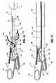
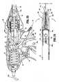
- a bipolar forceps 10for use with various surgical procedures and generally includes a housing 20, a handle assembly 30, a rotating assembly 80, a trigger assembly 70 and an end effector assembly 100 which mutually cooperate to grasp, seal and divide tubular vessels and vascular tissue 420 ( Fig. 20 ).
- a bipolar forceps 10for use in connection with endoscopic surgical procedures
- an open forceps 10'is also contemplated for use in connection with traditional open surgical procedures and is shown by way of example in Fig. 1A .
- the endoscopic versionis discussed in detail, however, it is contemplated that open forceps 10' also includes the same or similar operating components and features as described below.
- forceps 10includes a shaft 12 which has a distal end 14 dimensioned to mechanically engage the end effector assembly 100 and a proximal end 16 which mechanically engages the housing 20.
- shaft 12is bifurcated at the distal end 14 thereof to form ends 14a and 14b which are dimensioned to receive the end effector assembly 100 as best seen in Figs. 7 and 12 .
- the proximal end 16 of shaft 12includes notches 17a (See Figs. 23 and 29 ) and 17b (See Figs. 11 , 12 and 13 ) which are dimensioned to mechanically engage corresponding detents 83a ( Fig. 18A ) and 83b ( Fig.
- proximalas is traditional, will refer to the end of the forceps 10 which is closer to the user, while the term “distal” will refer to the end which is further from the user.
- forceps 10also includes an electrical interface or plug 300 which connects the forceps 10 to a source of electrosurgical energy, e.g., a generator (not shown).
- Plug 300includes a pair of prong members 302a and 302b which are dimensioned to mechanically and electrically connect the forceps 10 to the source of electrosurgical energy.
- An electrical cable 310extends from the plug 300 to a sleeve 99 which securely connects the cable 310 to the forceps 10.
- cable 310is internally divided into cable lead 310a and 310b which each transmit electrosurgical energy through their respective feed paths through the forceps 10 to the end effector assembly 100 as explained in more detail below.
- Handle assembly 30includes a fixed handle 50 and a movable handle 40.
- Fixed handle 50is integrally associated with housing 20 and handle 40 is movable relative to fixed handle 50 as explained in more detail below with respect to the operation of the forceps 10.
- Rotating assembly 80is preferably attached to a distal end 303 ( Fig. 18A ) of housing 20 and is rotatable approximately 180 degrees in either direction about a longitudinal axis "A".
- housing 20is formed from two (2) housing halves 20a and 20b which each include a plurality of interfaces 307a, 307b and 307c ( Fig. 13 ) which are dimensioned to mechanically align and engage one another to form housing 20 and enclose the internal working components of forceps 10.
- fixed handle 50which, as mentioned above is integrally associated with housing 20, takes shape upon the assembly of the housing halves 20a and 20b.
- housing halves 20a and 20bmay be assembled together in any fashion known in the art.
- alignment pins, snap-like interfaces, tongue and groove interfaces, locking tabs, adhesive ports, etc.may all be utilized either alone or in combination for assembly purposes.
- rotating assembly 80includes two halves 80a and 80b which, when assembled, enclose and engage the proximal end 16 of shaft 12 to permit selective rotation of the end effector assembly 100 as needed.
- Half 80aincludes a pair of detents 89a ( Fig. 13 ) which are dimensioned to engage a pair of corresponding sockets 89b (shown in phantom in Fig. 13 ) disposed within half 80b.
- Movable handle 40 and trigger assembly 70are preferably of unitary construction and are operatively connected to the housing 20 and the fixed handle 50 during the assembly process.
- end effector assembly 100is attached to the distal end 14 of shaft 12 and includes a pair of opposing jaw members 110 and 120.
- Movable handle 40 of handle assembly 30is ultimately connected to a drive rod 32 which, together, mechanically cooperate to impart movement of the jaw members 110 and 120 from an open position wherein the jaw members 110 and 120 are disposed in spaced relation relative to one another, to a clamping or closed position wherein the jaw members 110 and 120 cooperate to grasp tissue 420 ( Fig. 20 ) therebetween.
- Figs. 9 -11 and 20-29This is explained in more detail below with respect to Figs. 9 -11 and 20-29 .
- the forceps 10may be designed such that it is fully or partially disposable depending upon a particular purpose or to achieve a particular result.
- end effector assembly 100may be selectively and releasably engageable with the distal end 14 of the shaft 12 and/or the proximal end 16 of shaft 12 may be selectively and releasably engageable with the housing 20 and the handle assembly 30.
- the forceps 10would be considered "partially disposable" or "reposable", i.e., a new or different end effector assembly 100 (or end effector assembly 100 and shaft 12) selectively replaces the old end effector assembly 100 as needed .
- movable handle 40includes an aperture 42 defined therethrough which enables a user to grasp and move the handle 40 relative to the fixed handle 50.
- Handle 40also includes an ergonomically-enhanced gripping element 45 disposed along the inner peripheral edge of aperture 42 which is designed to facilitate gripping of the movable handle 40 during activation.
- gripping element 45may include one or more protuberances, scallops and/or ribs 43a, 43b and 43c, respectively, to facilitate gripping of handle 40.
- movable handle 40is selectively moveable about a pivot 69 from a first position relative to fixed handle 50 to a second position in closer proximity to the fixed handle 50 which, as explained below, imparts movement of the jaw members 110 and 120 relative to one another.
- housing 20encloses a drive assembly 21 which cooperates with the movable handle 40 to impart movement of the jaw members 110 and 120 from an open position wherein the jaw members 110 and 120 are disposed in spaced relation relative to one another, to a clamping or closed position wherein the jaw members 110 and 120 cooperate to grasp tissue therebetween.
- the handle assembly 30can generally be characterized as a four-bar mechanical linkage composed of the following elements: movable handle 40, a link 65, a cam-like link 36 and a base link embodied by fixed handle 50 and a pair of pivot points 37 and 67b.
- Movement of the handle 40activates the four-bar linkage which, in turn, actuates the drive assembly 21 for imparting movement of the opposing jaw members 110 and 120 relative to one another to grasp tissue therebetween. It is envisioned that employing a four-bar mechanical linkage will enable the user to gain a significant mechanical advantage when compressing the jaw members 110 and 120 against the tissue 420 as explained in further detail below with respect the operating parameters of the drive assembly 21. Although shown as a four-bar mechanical linkage, the present disclosure contemplates other linkages to effect relative motion of the jaw members 110 and 120 as is known in the art.
- fixed handle 50includes an channel 54 defined therein which is dimensioned to receive a flange 92 which extends proximally from movable handle 40.
- flange 92includes a fixed end 90 which is affixed to movable handle 40 and a t-shaped free end 93 which is dimensioned for facile reception within channel 54 of handle 50. It is envisioned that flange 92 may be dimensioned to allow a user to selectively, progressively and/or incrementally move jaw members 110 and 120 relative to one another from the open to closed positions.
- flange 92may include a ratchet-like interface which lockingly engages the movable handle 40 and, therefore, jaw members 110 and 120 at selective, incremental positions relative to one another depending upon a particular purpose.
- Other mechanismsmay also be employed to control and/or limit the movement of handle 40 relative to handle 50 (and jaw members 110 and 120) such as, e.g., hydraulic, semi-hydraulic, linear actuator(s), gas-assisted mechansims and/or gearing systems.
- housing halves 20a and 20b of housing 20when assembled, form an internal cavity 52 which predefines the channel 54 within fixed handle 50 such that an entrance pathway 53 and an exit pathway 58 are formed for reciprocation of the t-shaped flange end 93 therein.
- two generally triangular-shaped members 57a and 57bare positioned in close abutment relative to one another to define a rail or track 59 therebetween.
- the t-shaped end 93rides along track 59 between the two triangular members 57a and 57b according to the particular dimensions of the triangularly-shaped members 57a and 57b, which, as can be appreciated, predetermines part of the overall pivoting motion of handle 40 relative to fixed handle 50.
- handle 40moves in a generally arcuate fashion towards fixed handle 50 about pivot 69 which causes link 65 to rotate proximally about pivots 67a and 67b which, in turn, cause cam-like link 36 to rotate about pivots 37 and 69 in a generally proximal direction. Movement of the cam-like link 36 imparts movement to the drive assembly 21 as explained in more detail below. Moreover, proximal rotation of the link 65 about pivots 67a and 67b also causes a distal end 63 of link 65 to release, i.e., "unlock", the trigger assembly 70 for selective actuation. This feature is explained in detail with reference to Figs. 21-29 and the operation of the knife assembly 200.
- shaft 12includes distal and proximal ends 14 and 16, respectively.
- the distal end 14is bifurcated and includes ends 14a and 14b which, together, define a cavity 18 for receiving the end effector assembly 100.
- the proximal end 16includes a pair of notches 17a ( Fig. 29 ) and 17b ( Fig. 11 ) which are dimensioned to engage corresponding detents 83a and 83b ( Fig. 13 ) of the rotating assembly 80.
- actuation of the rotation assembly 80rotates the shaft 12 which, in turn, rotates the end effector assembly 100 to manipulate and grasp tissue 420.
- Shaft 12also includes a pair of longitudinally-oriented channels 19a ( Fig. 15 ) and 19b ( Fig. 12 ) which are each dimensioned to carry an electrosurgical cable lead 310a and 310b, respectively, therein for ultimate connection to each jaw member 120 and 110, respectively, as explained in more detail with reference to Figs. 14-17 below.
- Shaft 12also includes a pair of longitudinally oriented slots 197a and 197b disposed on ends 14a and 14b, respectively. Slots 197a and 197b are preferably dimensioned to allow longitudinal reciprocation of a cam pin 170 therein which, as explained below with reference to Figs. 23 and 24 , causes movement of the opposing jaw member 110 and 120 from the open to closed positions.
- Shaft 12also includes a pair of sockets 169a and 169b disposed at distal ends 14a and 14b which are dimensioned to receive a corresponding pivot pin 160.
- pivot pin 160secures jaws 110 and 120 to the shaft 12 between bifurcated distal ends 14a and 14b and mounts the jaw members 110 and 120 such that longitudinal reciprocation of the cam pin 170 rotates jaw members 110 and 120 about pivot pin 160 from the open to closed positions.
- Knife tube 34includes a rim 35 located at a proximal end thereof and a pair of opposing notches 230a and 230b ( Figs. 25 and 30 ) located at a distal end 229 thereof. As best shown in Fig.
- rim 35is dimensioned to engage a corresponding sleeve 78 disposed at a distal end of the trigger assembly 70 such that distal movement of the sleeve 78 translates the knife tube 34 which, in turn, actuates the knife assembly 200.
- a seal 193may be mounted atop the knife tube 34 and positioned between the knife tube 34 and the shaft 12. It is envisioned that the seal 193 may be dimensioned to facilitate reciprocation of the knife tube 34 within the shaft 12 and/or to protect the other, more sensitive, internal operating components of the forceps from undesirable fluid inundation during surgery. Seal 193 may also be employed to control/regulate pneumo-peritoneal pressure leakage through forceps 10 during surgery. Seal 193 preferably includes a pair of opposing bushings 195a and 195b which assure consistent and accurate reciprocation of the knife tube 34 within shaft 12 (See Fig 15 ).
- Notches 230a and 230bare preferably dimensioned to engage a corresponding key-like interface 211 of the knife assembly 200 which includes a pair of opposing detents 212a and 212b and a pair of opposing steps 214a and 214b.
- each detent and step arrangemente.g., 212a and 214a, respectively, securely engages a corresponding notch, e.g., 230a, such that the distal end of the step 214a abuts the distal end 229 of the knife tube 34. It is envisioned that engaging the knife tube 34 to the knife assembly 200 in this manner will assure consistent and accurate distal translation of the knife tube 34 through the tissue 420.
- the knife tube 34 and knife assembly 200are preferably assembled to operate independently from the operation of the drive assembly 21.
- knife assembly 200is dependent on the drive assembly 21 for activation purposes, i.e., the activation/movement of the drive assembly 21 (via handle assembly 30 and the internal working components thereof) "unlocks" the knife assembly 200 for selective, separation of the tissue.
- the drive assembly 21consists of both the drive rod 32 and the compression mechanism 24 which includes a number of cooperative elements which are described below with reference to Fig. 13 . It is envisioned that arranging the drive assembly 21 in this fashion will enable facile, selective engagement of the drive rod 32 within the compression mechanism 24 for assembly purposes.
- the housing 20may include a release mechanism (not shown) which enables selectively replacement of the drive rod 32 for disposal purposes.
- the forcepswill be considered “partially disposable” or “reposable”, i.e., the shaft 12, end effector assembly 100 and knife assembly 200 are disposable and/or replaceable whereas the housing 20 and handle assembly 30 are re-usable.
- drive rod 32includes a pair of chamfered or beveled edges 31a and 31b at a distal end thereof which are preferably dimensioned to allow facile reciprocation of the drive rod 32 through a knife carrier or guide 220 which forms a part of the knife assembly 200.
- a pin slot 39is disposed at the distal tip of the drive rod 32 and is dimensioned to house the cam pin 170 such that longitudinal reciprocation of the drive rod 32 within the knife tube 34 translates the cam pin 170, which, in turn, rotates the jaw members 110 and 120 about pivot pin 160.
- the cam pin 170rides within slots 172 and 174 of the jaw members 110 and 120, respectively, which causes the jaw members 110 and 120 to rotate from the open to closed positions about the tissue 420.
- the proximal end of the drive rod 32includes a tab 33 which is preferably dimensioned to engage a corresponding compression sleeve 28 disposed within the compression mechanism 24. Proximal movement of the sleeve 28 (as explained below with respect to Figs. 21-24 ) reciprocates (i.e., pulls) the drive rod 32 which, in turn, pivots the jaw members 110 and 120 from the open to closed positions.
- Drive rod 32also includes a donut-like spacer or o-ring 95 which is dimensioned to maintain pneumo-peritoneal pressure during endoscopic procedures. It is also envisioned that o-ring 95 may also prevent the inundation of surgical fluids which may prove detrimental to the internal operating components of the forceps 10. O-ring 95 is made also be made from a material having a low coefficient of friction to facilitate uniform and accurate reciprocation of the drive rod 32 within the knife tube 34.
- Knife assembly 200is disposed between opposing jaw members 110 and 120 of the end effector assembly 100.
- the knife assembly 200 and the end effector assembly 100are independently operable, i.e., the trigger assembly 70 actuates the knife assembly 200 and the handle assembly 30 actuates the end effector assembly 100.
- Knife assembly 200includes a bifurcated knife bar or rod 210 having two forks 210a and 210b and a knife carrier or guide 220.
- Knife forks 210a and 210binclude the above-described key-like interfaces 211 (composed of steps 214a, 214b and detents 212a, 212b, respectively) disposed at the proximal end thereof for engaging the knife tube 34 (as described above) and a common distal end 206 which carries a blade 205 thereon for severing tissue 420.
- each fork 210a and 210bincludes a taper 213a and 213b, respectively, which converge to form common distal end 206. It is envisioned that the tapers 213a and 213b facilitate reciprocation of the knife blade 205 through the end effector assembly 100 as described in more detail below and as best illustrated in Fig. 30 .
- Each fork 210a and 210balso includes a tapered shoulder portion 221 a and 221 b disposed along the outer periphery thereof which is dimensioned to engage a corresponding slot 223a and 223b, respectively, disposed in the knife carrier or guide 220 (See Fig. 16 ). It is envisioned that this shoulder portion 221 a, 221 b and slot 223a, 223b arrangement may be designed to restrict and/or regulate the overall distal movement of the blade 205 after activation.
- Each fork 210a and 210balso includes an arcuately-shaped notch 215a and 215b, respectively disposed along the inward edge thereof which is dimensioned to facilitate insertion of a roller or bushing 216 disposed between the jaw members 110 and 120 during assembly.
- knife assembly 200also includes a knife carrier or guide 220 which includes opposing spring tabs 222a and 222b at a proximal end thereof and upper and lower knife guides 224a and 224b, respectively, at the distal end thereof.
- the inner facing surface of each spring tab, e.g., 222b,is preferably dimensioned to matingly engage a corresponding chamfered edge, e.g., 31b of the drive rod 32 ( Fig. 16 ) and the outer facing surface is preferably dimensioned for friction-fit engagement with the inner periphery of the shaft 12.
- a knife carrier or guide 220which includes opposing spring tabs 222a and 222b at a proximal end thereof and upper and lower knife guides 224a and 224b, respectively, at the distal end thereof.
- the inner facing surface of each spring tab, e.g., 222bis preferably dimensioned to matingly engage a corresponding chamfered edge, e.g., 31b of
- knife carrier 220also includes a drive rod channel 225 defined therethrough which is dimensioned to allow reciprocation of the drive rod 32 during the opening and closing of the jaw members 110 and 120.
- Knife guide 220also includes rests 226a and 226b which extend laterally therefrom which abut the proximal ends 132, 134 of the jaw members 110 and 120 when disposed in the closed position.
- Knife guides 224a and 224bpreferably include slots 223a and 223b, respectively, located therein which guide the knife forks 210a and 210b therealong during activation to provide consistent and accurate reciprocation of the knife blade 205 through the tissue 420. It is envisioned that slots 223a and 223b also restrict undesirable lateral movements of the knife assembly 200 during activation.
- the knife carrier 220is positioned at a point slightly beyond the shoulder portions 221 a and 221 b when assembled.
- the knife assembly 200also includes a roller or bushing 216 which is dimensioned to mate with the inner peripheral edge of each fork 210a and 210b such that, during activation, the forks 210a and 210b glide over the roller or bushing 216 to assure facile and accurate reciprocation of the knife assembly 200 through the tissue 420.
- Bushing 216is also dimensioned to seat between opposing jaw members 110 and 120 and is preferably secured therebetween by pivot pin 160. As mentioned above, the arcuately-shaped notches 215a and 215b facilitate insertion of the bushing 216 during assembly.
- the end effector assembly 100includes opposing jaw members 110 and 120 which are seated within cavity 18 defined between bifurcated ends 14a and 14b of shaft 12. Jaw members 110 and 120 are generally symmetrical and include similar component features which cooperate to permit facile rotation about pivot pin 160 to effect the sealing and dividing of tissue 420. As a result and unless otherwise noted, only jaw member 110 and the operative features associated therewith are described in detail herein but as can be appreciated, many of these features apply to jaw member 120 as well.
- jaw member 110includes a pivot flange 166 which has an arcuately-shaped inner surface 167 which is dimensioned to allow rotation of jaw member 110 about bushing 216 and pivot pin 160 upon reciprocation of drive rod 32 as described above.
- Pivot flange 166also includes a cam slot 172 which is dimensioned to engage cam pin 170 such that longitudinal movement of the drive rod 32 causes the cam pin 170 to ride along cam slot 172.
- cam slot 172may be dimensioned to allow different rotational paths depending upon a particular purpose or to achieve a particular result.
- commonly assigned, co-pending U.S. Patent No. 6,511 480describes a two-stage cam slot arrangement which, as can be appreciated, provides a unique rotational path for the jaw members about the pivot point.
- Pivot flange 166also includes a recess 165 which is preferably dimensioned to secure one free end of the bushing 216 between jaw members 110 and 120.
- the inner periphery of recess 165is preferably dimensioned to receive pivot pin 160 therethrough to secure the jaw member 110 to the shaft 12.
- Jaw member 120includes a similar recess 175 ( Fig. 14 ) which secures the opposite end of bushing 216 and jaw member 120 to shaft 12.
- Jaw member 110also includes a jaw housing 116, an insulative substrate or insulator 114 and an electrically conducive surface 112.
- Jaw housing 116includes a groove (not shown - See groove 179 of jaw member 120) defined therein which is dimensioned to engage a ridge-like interface 161 disposed along the outer periphery of insulator 114.
- Insulator 114is preferably dimensioned to securely engage the electrically conductive sealing surface 112. This may be accomplished by stamping, by overmolding, by overmolding a stamped electrically conductive sealing plate and/or by overmolding a metal injection molded seal plate. All of these manufacturing techniques produce an electrode having an electrically conductive surface 112 which is substantially surrounded by an insulating substrate 114.
- the insulator 114, electrically conductive sealing surface 112 and the outer, non-conductive jaw housing 116are preferably dimensioned to limit and/or reduce many of the known undesirable effects related to tissue sealing, e.g., flashover, thermal spread and stray current dissipation.
- the electrically conductive sealing surface 112may also include a pinch trim 119 ( Fig. 25 ) which facilitates secure engagement of the electrically conductive surface 112 to the insulating substrate 114 and also simplifies the overall manufacturing process. It is envisioned that the electrically conductive sealing surface 112 may also include an outer peripheral edge which has a radius and the insulator 114 meets the electrically conductive sealing surface 112 along an adjoining edge which is generally tangential to the radius and/or meets along the radius. Preferably, at the interface, the electrically conductive surface 112 is raised relative to the insulator 114.
- Insulator 114also includes an inwardly facing finger 162 which abuts pivot flange 166 and is designed to restrict / reduce proximal tissue spread and/or isolate the electrically conductive sealing surface 112 from the remaining end effector assembly 100 during activation.
- the electrically conductive surface 112 and the insulator 114when assembled, form a longitudinally-oriented channel 168a, 168b defined therethrough for reciprocation of the knife blade 205. More particularly, and as best illustrated in Fig. 14 , insulator 114 includes a first channel 168b which aligns with a second channel 168a on electrically conductive sealing surface 112 to form the complete knife channel.
- the knife channel 168a, 168bfacilitates longitudinal reciprocation of the knife blade 205 along a preferred cutting plane "B-B" to effectively and accurately separate the tissue 420 along the formed tissue seal 425 (See Figs. 27, 28 and 31 ).
- jaw member 120includes similar elements which include: a pivot flange 176 which has an arcuately-shaped inner surface 177, a cam slot 174, and a recess 175; a jaw housing 126 which includes a groove 179 which is dimensioned to engage a ridge-like interface 171 disposed along the outer periphery of an insulator 124; the insulator 124 which includes an inwardly facing finger 172 which abuts pivot flange 176; and an electrically conducive sealing surface 122 which is dimensioned to securely engage the insulator 124.
- the electrically conductive surface 122 and the insulator 124when assembled, form a longitudinally-oriented channel 178a, 178b defined therethrough for reciprocation of the knife blade 205.
- each jaw membere.g., 110
- each jaw memberincludes a uniquely-designed electrosurgical cable path disposed therethrough which transmits electrosurgical energy to the electrically conductive sealing surfaces 112, 122.
- jaw member 110includes a cable guide 181a disposed atop pivot flange 166 which directs cable lead 310a towards an aperture 188 disposed through jaw housing 116.
- Aperture 188directs cable lead 310a towards electrically conductive sealing surface 112 through a window 182 disposed within insulator 114.
- a second cable guide 181 bsecures cable lead 310a along the predefined cable path through window 182 and directs a terminal end 310a' of the cable lead 310a into crimp-like electrical connector 183 disposed on an opposite side of the electrically conductive sealing surface 112.
- cable lead 310ais held loosely but securely along the cable path to permit rotation of the jaw member 110 about pivot 169.
- Jaw member 120includes a similar cable path disposed therein and therethrough which includes similarly dimensioned cable guides, apertures and electrical connectors which are not shown in the accompanying illustrations.
- Figs. 15-17also show the presently disclosed feed path for both electrosurgical cable leads 310a and 310b along the outer periphery of the shaft 12 and through each jaw member 110 and 120. More particularly, Fig. 15 shows a cross section of the electrosurgical cable leads 310a and 310b disposed within channels 19a and 19b, respectively, along shaft 12. Figs. 16 and 17 show the feed path of the cable leads 310a and 310b from the opposite channels 19a and 19b of the shaft 12 through the pivot flanges 166 and 176 of the jaw members 110 and 120, respectively.
- this unique cable feed path for cable leads 310a and 310b from the shaft 12 to the jaw members 110 and 120not only electrically isolates each jaw member 100 and 120 but also allows the jaw members 110 and 120 to pivot about pivot pin 160 without unduly straining or possibly tangling the cable leads 310a and 310b.
- the crimp-like electrical connector 183(and the corresponding connector in jaw member 120) greatly facilitates the manufacturing and assembly process and assures a consistent and tight electrical connection for the transfer of energy through the tissue 420.
- the outer surface of shaft 12may be covered by heat shrink tubing 500 or the like which protects the cable leads 310a and 310b from undue wear and tear and secures cable leads 310a and 310b within their respective channels 19a and 19b.
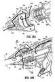
- Figs. 18A and 18Bshow the feed path of the cable leads 310a and 310b through the rotating assembly 80 which, again, allows the user added flexibility during the use of the forceps 10 due to the uniqueness of the feed path. More particularly, Fig. 18A shows the feed path of cable lead 310a through half 80a of the rotating assembly 80 and Fig. 18B shows the path of cable leads 310a and 310b as the cable leads 310a and 310b feed through the instrument housing 20a, through half 80a of the rotating assembly 80 and to the channels 19a and 19b of the shaft 12. Fig. 18A only shows the feed path of cable lead 310a through half 80a of the rotating assembly 80, however, as can be appreciated, cable lead 310b (shown broken in Fig. 19 ) is positioned in a similar fashion within half 80b of rotating assembly 80.
- each cable lead 310a and 310bare fed through respective halves 80a and 80b of the rotating assembly 80 in such a manner to allow rotation of the shaft 12 (via rotation of the rotating assembly 80) in the clockwise or counter-clockwise direction without unduly tangling or twisting the cable leads 310a and 310b. More particularly, each cable lead, e.g., 310a, is looped through each half 80a of the rotating assembly 80 to form slack-loops 321a and 321b which traverse either side of longitudinal axis "A".
- Slack-loop 321 aredirects cable lead 310a across one side of axis "A" and slack-loop 321 b returns cable lead 310a across axis "A".
- feeding the cable leads 310a and 310b through the rotating assembly 80 in this fashionallows the user to rotate the shaft 12 and the end effector assembly 100 without unduly straining or tangling the cable leads 310a and 310b which may prove detrimental to effective sealing.
- this loop-like cable feed pathallows the user to rotate the end effector assembly 100 about 180 degrees in either direction without straining the cable leads 310a and 310b.
- the presently disclosed cable lead feed pathis envisioned to rotate the cable leads 310a and 310b approximately 178 degrees in either direction.
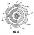
- Fig. 19shows an internal view of half 80a of the rotating assembly 80 as viewed along axis "A" to highlight the internal features thereof. More particularly, at least one stop 88 is preferably positioned within each rotating half 80a and 80b which operates to control the overall rotational movement of the rotating assembly 80 to about 180 degree in either direction.
- the stop member 88is dimensioned to interface with a corresponding notch 309c disposed along the periphery of outer flange 309 to prevent unintended over-rotation of the rotating assembly 80 which may unduly strain one or both of the cable leads 310a and 310b.
- Fig. 18Bshows the feed path of the electrical cable leads 310a and 310b from the housing 20a, through the rotating assembly 80 and to the shaft 12. It is envisioned that the cable leads 310a and 310b are directed through each part of the forceps 10 via a series of cable guide members 311a-311g disposed at various positions through the housing 20 and rotating assembly 80. As explained below, a series of mechanical interfaces, e.g., 309a, 309b ( Fig. 13 ) and 323a, 323b ( Fig. 13 ) may also be dimensioned to contribute in guiding cables 310a and 310b through the housing 20 and rotating assembly 80.
- a series of mechanical interfacese.g., 309a, 309b ( Fig. 13 ) and 323a, 323b ( Fig. 13 ) may also be dimensioned to contribute in guiding cables 310a and 310b through the housing 20 and rotating assembly 80.
- Fig. 13which shows the exploded view of the housing 20, rotating assembly 80, trigger assembly 70 and handle assembly 30, it is envisioned that all of these various component parts along with the shaft 12 and the end effector assembly 100 are assembled during the manufacturing process to form a partially and/or fully disposable forceps 10.
- the shaft 12 and/or end effector assembly 100may be disposable and, therefore, selectively/releasably engagable with the housing 20 and rotating assembly 80 to form a partially disposable forceps 10 and/or the entire forceps 10 may be disposable after use.
- Housing 20is preferably formed from two housing halves 20a and 20b which engage one another via a series of mechanical interfaces 307a, 307b, 307c and 308a, 308b, 308c respectively, to form an internal cavity 300 for housing the hereindescribed internal working components of the forceps 10.
- housing halves 20a and 20are generally symmetrical and, unless otherwise noted, a component described with respect to housing half 20a will have a similar component which forms a part of housing half 20b.
- Housing half 20aincludes proximal and distal ends 301a and 303a, respectively.
- Proximal end 301ais preferably dimensioned to receive an electrical sleeve 99 which secures the electrosurgical cable 310 ( Fig. 1 ) within the housing 20.
- paired cable 310splits into two electrosurgical cable leads 310a and 310b which are subsequently fed through the housing 20 to ultimately transmit different electrical potentials to the opposing jaw members 110 and 120.
- various cable guides 311a-311gare positioned throughout the housing 20 and the rotating assembly 80 to direct the cable leads 310a and 310b to the channels 19a and 19b disposed along the outer periphery of the shaft 12.
- the distal end 303ais generally arcuate in shape such that, when assembled, distal ends 303a and 303b form a collar 303 ( Fig. 13 ) which extends distally from the housing 20.
- Each distal end 303a, 303b of the collar 303includes an outer flange 309a, 309b and a recess 323a, 323b which cooperate to engage corresponding mechanical shoulders 84a, 84b ( Fig. 29 ) and flanges 87a, 87b, respectively, disposed within the rotating assembly 80.
- the interlocking engagement of the flanges 309a, 309b with the shoulders 84a, 84b and the recesses 323a, 323b with the flanges 87a, 87bare dimensioned to allow free rotation about of the rotating assembly 80 about collar 303 when assembled.
- the stop member(s) 88 and the notch(es)mechanically cooperate to limit rotational movement of the rotating assembly 80 to avoid straining cable leads 310a and 310b.
- Each distal end 303a, 303b of collar 303also includes an inner cavity 317a and 317b ( Figs. 9 and 21 ), respectively, defined therein which is dimensioned to permit free rotation of the shaft 12, knife tube 34 and cable leads 310a and 310b housed therein.
- a plurality of detents 89a located within rotating assembly 80engage a corresponding plurality of sockets 89b ( Fig. 13 ) disposed within rotating half 80b to poise the rotating assembly 80 in rotational relationship atop collar 303.
- Housing half 20aalso includes a plurality of hub-like pivot mounts 329a, 331 a and 333a which as explained in more detail below with respect to the operation of the instrument, cooperate with opposite hub-like pivot mounts (shown in phantom in Fig. 13 ) disposed on housing half 20b to engage the free ends of pivot pins 37, 67b and 77, respectively, which are associated with the different operating components described below.
- each of these mounts 329a, 331 a and 333aprovide a fixed point of rotation for each pivoting element, namely, cam link 36, handle link 65 and trigger assembly 70, respectively.
- fixed handle 50which takes shape upon the assembly of housing 20 includes a scallop-like outer surface 51 and an internal cavity 52 defined therein. As mentioned above with respect to the discussion of Fig. 11 , these elements and the other internal elements of the fixed handle 50 cooperate with movable handle 40 to activates the four-bar mechanical linkage which, in turn, actuates the drive assembly 21 for imparting movement of the opposing jaw members 110 and 120 relative to one another to grasp tissue 420 therebetween.
- the handle assembly 30which includes the above-mentioned fixed handle 50 and movable handle 40 also includes the cam link 36 which is generally triangular in shape.
- the cam linkincludes an upper piston 38, a fixed pivot 37 and a handle pivot 69.
- Cam linkis assembled within the internal cavity 300 of housing 20 between housing halves 20a and 20b. More particularly, fixed pivot 37 is rotatingly mounted within fixed mounts 329a and 329b between opposing housing halves 20a and 20b and the handle pivot 69 is rotatingly mounted within the bifurcated end of handle 40 through apertures 68a and 68b.
- Cam piston 38is poised within a longitudinal channel 25c defined through the drive assembly 70 (explained in further detail below with respect to the discussion of the drive assembly 70) in abutting relationship with a compression tab 25 such that movement of the handle 40 rotates piston 38 proximally against coil spring 22.
- Link 65is also associated with the handle assembly 30 and forms an integral part of the four-bar mechanical linkage.
- Link 65includes a distal end 63 and two pivot pins 67a and 67b.
- Pivot pin 67aengages apertures 68a and 68b disposed within the movable handle 40 and pivot 67b engages fixed mounts 331 a and 331 b between housing halves 20a and 20b such that movement of the handle 40 towards fixed handle 50 pivots link 65 about pivots 67a and 67b.
- distal end 63acts as a lockout for the trigger assembly 70.
- Movable handle 40includes a flange 92 which is preferably mounted to the movable handle 40 by pins 46a and 46b which engage apertures 41 a and 41 b disposed within handle 40 and apertures 91 a and 91 b disposed within flange 92, respectively. Other methods of engagement are also contemplated, snap-lock, spring tab, etc.
- Flange 92also includes a t-shaped distal end 93 which, as mentioned above with respect to Fig. 11 , rides within a predefined channel 54 disposed within fixed handle 50. Additional features with respect to the t-shaped end 93 are explained below in the detailed discussion of the operational features of the forceps 10.
- a drive assembly 21is preferably positioned within the housing 20 between housing halves 20a and 20b.
- the drive assembly 21includes the previously described drive rod 32 and the compression mechanism 24.
- Compression mechanism 24includes a compression sleeve 27 which is telescopically and/or slidingly disposed within a spring mount 26.
- the distal end 28 of the compression sleeve 27is preferably C-shaped and dimensioned to engage the tab 33 disposed at the proximal end of drive rod 32 such that longitudinal movement of the compression sleeve 27 actuates the drive rod 32.
- the proximal end of the compression sleeve 27is dimensioned to engage a barbell-shaped compression tab 25 which is disposed within a longitudinal slot 25s of the spring mount 26.
- the compression sleeve 27also includes a longitudinal slot or channel 25c which is longitudinally aligned with slot 25s and is dimensioned to receive the cam piston 38 of the cam link 36 described above.
- the proximal end of spring mount 26includes a circular flange 23 which is dimensioned to bias the compression spring 22 once the compression mechanism 24 is assembled and seated within housing 20 ( Fig. 11 ).
- the distal end of spring mount 26includes a flange 25f which restricts distal movement of the tab 25 to within the slot 25s of the spring mount 26 and biases the opposite end the spring 22.
- spring 22is poised for compression atop spring mount 26 upon actuation of the handle assembly 30. More particularly, movement of the cam piston 38 within slot 25c (via movement of handle assembly 30) moves the tab 25 atop slot 25s and reciprocates the compression sleeve 27 within the spring mount 26 to compress the spring 22. Proximal movement of the compression sleeve 27 imparts proximal movement to the drive rod 32 which closes jaw members 110 and 120 about tissue 420 ( Fig. 26 ). Compression of the spring 22 may be viewed through one or more windows 340 disposed within the housing halves, e.g., 20b.
- Fig. 13also shows the trigger assembly 70 which activates the knife assembly 200 as described above with respect to Fig. 12 .
- trigger assembly 70includes an actuator 73 having a cuff-like distal end 78 which is dimensioned to receive the proximal rim 35 of the knife tube 34.
- a drive pin 74extends laterally from the proximal end of actuator 73.
- Trigger assembly 70also includes an ergonomically enhanced finger tab 72 having opposing wing-like flanges 72a and 72b which are envisioned to facilitate gripping and firing of the trigger assembly during surgery.
- the compression sleeve 27is dimensioned to slide internally within actuator 73 when the forceps 10 is assembled.
- the actuator 73when activated, can slide distally along the outer periphery of compression sleeve 27 to actuate the knife assembly 200 as described above with respect to Fig. 12 .
- the drive pin 74is dimensioned to ride along a pair of guide rails 71 a and 71 b disposed within a bifurcated tail portion of finger tab 72 which includes ends 76a and 76b, respectively.
- a hinge or pivot pin 77mounts the finger tab 72 between housing halves 20a and 20 within mounts 333a and 333b.
- a torsion spring 75may also be incorporated within the trigger assembly 70 to facilitate progressive and consistent longitudinal reciprocation of the actuator 73 and knife tube 34 to assure reliable separation along the tissue seal 425 ( Figs. 27 and 28 ).
- the trigger assembly 70is configured in a proximal, "pre-loaded” configuration prior to activation. This assures accurate and intentional reciprocation of the knife assembly 200.
- the "preload" configuration of the torsion spring 75acts as an automatic recoil of the knife assembly 200 to permit repeated reciprocation through the tissue as needed.
- a plurality of gripping elements 71is preferably incorporated atop the finger tab 72 and wing flanges 72a and 72b to enhance gripping of the finger tab 72.
- the trigger assembly 70is initially prevented from firing due to the unique configuration of the distal end 63 of the link 65 which abuts against the finger tab 72 and "locks" the trigger assembly 70 prior to actuation of the handle assembly 30.
- the opposing jaw members 110 and 120may be rotated and partially opened and closed without unlocking the trigger assembly 70 which, as can be appreciated, allows the user to grip and manipulate the tissue 420 without premature activation of the knife assembly 200.
- the t-shaped end 93 of flange 92is completely reciprocated within channel 54 and seated within a pre-defined catch basin 62 (explained below) will the distal end 63 of link 65 move into a position which will allow activation of the trigger assembly 70.
- Figs. 21-29The operating features and relative movements of the internal working components of the forceps 10 are shown by phantom representation and directional arrows and are best illustrated in Figs. 21-29 .
- a predefined channel 54is formed within the cavity 52 of fixed handle 50.
- the channel 54includes entrance pathway 53 and an exit pathway 58 for reciprocation of the flange 92 and the t-shaped end 93 therein.
- the two generally triangular-shaped members 57a and 57bare positioned in close abutment relative to one another and define track 59 disposed therebetween.
- FIGs. 21 and 22show the initial actuation of handle 40 towards fixed handle 50 which causes the free end 93 of flange 92 to move generally proximally and upwardly along entrance pathway 53.
- the t-shaped end 93rides along track 59 between the two triangular members 57a and 57b.
- channel 197may be dimensioned slightly larger than needed to take into account any dimensional inconsistencies with respect to manufacturing tolerances of the various operating components of the end effector assembly 100 ( Fig. 24 )
- the utilization of a four-bar linkagewill enable the user to selectively compress the coil spring 22 a specific distance which, in turn, imparts a specific load on the drive rod 32.
- the drive rod 32 loadis converted to a torque about the jaw pivot 160 by way of cam pin 170.
- a specific closure forcecan be transmitted to the opposing jaw members 110 and 120.
- window 340 disposed in the housing 20may include graduations, visual markings or other indicia which provide feedback to the user during compression of the handle assembly 30.
- the usercan thus selectively regulate the progressive closure forces applied to the tissue 420 to accomplish a particular purpose or achieve a particular result.
- the window 340may include a specific visual indicator which relates to the proximal-most position of flange 93 prior to engagement within the catch basin 62.
- the jaw members 110 and 120may be opened, closed and rotated to manipulate tissue 420 until sealing is desired without unlocking the trigger assembly 70. This enables the user to position and re-position the forceps 10 prior to activation and sealing. More particularly, as illustrated in Fig. 4 , the end effector assembly 100 is rotatable about longitudinal axis "A" through rotation of the rotating assembly 80. As mentioned above, it is envisioned that the unique feed path of the cable leads 310a and 310b through the rotating assembly 80, along shaft 12 and, ultimately, through the jaw members 110 and 120 enable the user to rotate the end effector assembly 100 about 180 degrees in both the clockwise and counterclockwise direction without tangling or causing undue strain on the cable leads 310a and 310b. As can be appreciated, this facilitates the grasping and manipulation of tissue 420.
- a series of stop members 150a-150care preferably employed on the inner facing surfaces of the electrically conductive sealing surfaces 112 and 122 to facilitate gripping and manipulation of tissue and to define a gap "G" ( Fig. 24 ) between opposing jaw members 110 and 120 during sealing and cutting of tissue.
- handle 40may be compressed fully such that the t-shaped end 93 of flange 92 clears a predefined rail edge 61 located atop the triangular-shaped members 57a and 57b. Once end 93 clears edge 61, distal movement of the handle 40 and flange 92, i.e., release, is redirected by edge 61 into a catch basin 62 located within the exit pathway 58. More particularly, upon a slight reduction in the closing pressure of handle 40 against handle 50, the handle 40 returns slightly distally towards entrance pathway 53 but is re-directed towards exit pathway 58.
- end effector assembly 100 and/or the jaw members 110 and 120may be dimensioned to off-load some of the excessive clamping forces to prevent mechanical failure of certain internal operating elements of the end effector 100.
- the combination of the four-bar mechanical advantage along with the compressive force associated with the compression spring 22facilitate and assure consistent, uniform and accurate closure pressure about the tissue 420.
- the usercan either cauterize, coagulate/desiccate, seal and/or simply reduce or slow bleeding.
- two mechanical factorsplay an important role in determining the resulting thickness of the sealed tissue and effectiveness of the seal 425, i.e., the pressure applied between opposing jaw members 110 and 120 and the gap distance "G" between the opposing sealing surfaces 112, 122 of the jaw members 110 and 120 during the sealing process.
- thickness of the resulting tissue seal 425cannot be adequately controlled by force alone. In other words, too much force and the two jaw members 110 and 120 would touch and possibly short resulting in little energy traveling through the tissue 420 thus resulting in a bad tissue seal 425. Too little force and the seal 425 would be too thick.
- Applying the correct forceis also important for other reasons: to oppose the walls of the vessel; to reduce the tissue impedance to a low enough value that allows enough current through the tissue 420; and to overcome the forces of expansion during tissue heating in addition to contributing towards creating the required end tissue thickness which is an indication of a good seal 425.
- the electrically conductive sealing surfaces 112, 122 of the jaw members 110, 120are relatively flat to avoid current concentrations at sharp edges and to avoid arcing between high points.
- jaw members 110 and 120are preferably manufactured to resist bending.
- the jaw members 110 and 120may be tapered along the width thereof. which is advantageous for two reasons: 1) the taper will apply constant pressure for a constant tissue thickness at parallel; 2) the thicker proximal portion of the jaw members 110 and 120 will resist bending due to the reaction force of the tissue 420.
- At least one jaw member, e.g., 110may include a stop member, e.g., 150a, which limits the movement of the two opposing jaw members 110 and 120 relative to one another ( Figs. 6 and 7 ).
- the stop member, e.g., 150aextends from the sealing surface 112, 122 a predetermined distance according to the specific material properties (e.g., compressive strength, thermal expansion, etc.) to yield a consistent and accurate gap distance "G" during sealing ( Fig. 24 ).
- the gap distance between opposing sealing surfaces 112 and 122 during sealingranges from about 0.001 inches (0.03 mm) to about 0.005 inches (0.1 mm) and, more preferably, between about 0.002 (0.05 mm) and about 0.003 inches (0.08 mm).
- stop members 150a-150care made from an insulative material, e.g., parylene, nylon and/or ceramic and are dimensioned to limit opposing movement of the jaw members 110 and 120 to within the above mentioned gap range. It is envisioned that the stop members 150a-150c may be disposed on one or both of the jaw members 110 and 120 depending upon a particular purpose or to achieve a particular result.
- an insulative materiale.g., parylene, nylon and/or ceramic
- the non-conductive stop members 150a-150care molded onto the jaw members 110 and 120 (e.g., overmolding, injection molding, etc.), stamped onto the jaw members 110 and 120 or deposited (e.g., deposition) onto the jaw members 110 and 120.
- one techniqueinvolves thermally spraying a ceramic material onto the surface of the jaw member 110 and 120 to form the stop members 150a-150c.
- thermal spraying techniquesare contemplated which involve depositing a broad range of heat resistant and insulative materials on various surfaces to create stop members for controlling the gap distance between electrically conductive surfaces 112, 122.
- Other techniques for disposing the stop members 150a-150c on the electrically conductive surfaces 112 and 122are also contemplated, e.g., slide-on, snap-on, adhesives, molds, etc.
- the stop members 150a-150cprotrude about 0.001 inches (0.03 mm) to about 0.005 (0.1 mm) and preferably about 0.002 inches (0.05 mm) to about 0.003 (0.08 mm) inches from the inner-facing surfaces 112, 122 of the jaw member 110 and 120, in some cases it may be preferable to have the stop members 150a-150c protrude more or less depending upon a particular purpose.
- the type of material used for the stop members 150a-150c and that material's ability to absorb the large compressive closure forces between jaw members 110 and 120will vary and, therefore, the overall dimensions of the stop members 150a-150c may vary as well to produce the desired gap distance "G".
- the compressive strength of the material along with the desired or ultimate gap distance "G" required (desirable) for effective sealingare parameters which are carefully considered when forming the stop members 150a-150c and one material may have to be dimensioned differently from another material to achieve the same gap distance or desired result.
- the compressive strength of nylonis different from ceramic and, therefore, the nylon material may have to be dimensioned differently, e.g., thicker, to counteract the closing force of the opposing jaw members 110 and 120 and to achieve the same desired gap distance "G"' when utilizing a ceramic stop member.
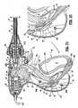
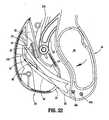
- a tissue seal 425forms isolating two tissue halves 420a and 420b.
- the usermust remove and replace the forceps 10 with a cutting instrument (not shown) to divide the tissue halves 420a and 420b along the tissue seal 425.
- a cutting instrumentnot shown
- the present disclosureincorporates a knife assembly 200 which, when activated via the trigger assembly 70, progressively and selectively divides the tissue 420 along the ideal tissue plane "B-B" in an accurate and precise manner to effectively and reliably divide the tissue 420 into two sealed halves 420a and 420b ( Fig. 31 ) with a tissue gap 430 therebetween.
- the reciprocating knife assembly 200allows the user to quickly separate the tissue 420 immediately after sealing without substituting a cutting instrument through a cannula or trocar port 410.
- accurate sealing and dividing of tissue 420is accomplished with the same forceps.
- knife blade 205may also be coupled to the same or an alternative electrosurgical energy source to facilitate separation of the tissue 420 along the tissue seal 425 (Not shown).
- the angle of the blade tip 207 of the knife blade 205may be dimensioned to provide more or less aggressive cutting angles depending upon a particular purpose.
- the blade tip 207may be positioned at an angle which reduces "tissue wisps" associated with cutting.
- the blade tip 207may be designed having different blade geometries such as serrated, notched, perforated, hollow, concave, convex etc. depending upon a particular purpose or to achieve a particular result.
- the blade tip 207may have a relatively sharp leading edge, it is also envisioned that the blade tip 207 may be substantially blunt or dull. More particularly, it is contemplated that the combination of the closure force between the jaw members 110 and 120 together with the uniquely designed stop members 150a-150c grip and hold the tissue firmly between the jaw members 110 and 120 to permit cutting of the tissue by blade tip 207 even if tip 207 is substantially blunt. As can be appreciated, designing the blade tip 207 blunt eliminates concerns relating to utilizing sharp objects with the surgical field.
- the jaw members 110 and 120may be opened by re-grasping the handle 40 as explained below.
- the knife assembly 200generally cuts in a progressive, uni-directional fashion (i.e., distally), however, it is contemplated that the knife blade may dimensioned to cut bi-directionally as well depending upon a particular purpose.
- the force associated with the recoil of the trigger spring 75may be utilized to with a second blade (not shown) which is designed to cut stray tissue wisps or dangling tissue upon recoil of the knife assembly.
- re-initiation or re-grasping of the handle 40again moves t-shaped end 93 of flange 92 generally proximally along exit pathway 58 until end 93 clears a lip 61 disposed atop triangular-shaped members 57a, 57b along exit pathway 58.
- lip 61is sufficiently cleared, handle 40 and flange 92 are fully and freely releasable from handle 50 along exit pathway 58 upon the reduction of grasping/gripping pressure which, in turn, returns the jaw members 110 and 120 to the open, pre-activated position.
- the forceps 10may include a sensor or feedback mechanism (not shown) which automatically selects the appropriate amount of electrosurgical energy to effectively seal the particularly-sized tissue grasped between the jaw members 110 and 120.
- the sensor or feedback mechanismmay also measure the impedance across the tissue during sealing and provide an indicator (visual and/or audible) that an effective seal has been created between the jaw members 110 and 120.
- the trigger assembly 70may include other types of recoil mechanism which are designed to accomplish the same purpose, e.g., gas-actuated recoil, electrically-actuated recoil (i.e., solenoid), etc. It is also envisioned that the forceps 10 may be used to dive / cut tissue without sealing. Alternatively, the knife assembly may be coupled to the same or alternate electrosurgical energy source to facilitate cutting of the tissue.
- one of the jaw membersmay include a cam-actuated blade member which is seated within one of the jaw members which, upon reciprocation of a cam member, is biased to cut tissue along a plane substantially perpendicular to the longitudinal axis "A".
- a shape memory alloymay be employed to cut the tissue upon transformation from an austenitic state to a martenistic state with a change in temperature or stress.
- SMAsare a family of alloys having anthropomorphic qualities of memory and trainability and are particularly well suited for use with medical instruments. SMAs have been applied to such items as actuators for control systems, steerable catheters and clamps.
- One of the most common SMAsis Nitinol which can retain shape memories for two different physical configurations and changes shape as a function of temperature.
- SMAshave been developed based on copper, zinc and aluminum and have similar shape memory retaining features.
- SMAsundergo a crystalline phase transition upon applied temperature and/or stress variations.
- a particularly useful attribute of SMAsis that after it is deformed by temperature/stress, it can completely recover its original shape on being returned to the original temperature. This transformation is referred to as a thermoelastic martenistic transformation.
- thermoelastic martenistic transformationoccurs over a temperature range which varies with the composition of the alloy, itself, and the type of thermal-mechanical processing by which it was manufactured.
- the temperature at which a shape is "memorized" by an SMAis a function of the temperature at which the martensite and austenite crystals form in that particular alloy.
- Nitinol alloyscan be fabricated so that the shape memory effect will occur over a wide range of temperatures, e.g., -270° to +100° Celsius.
- jaw members as shown and described hereindepict the jaw members movable in a pivotable manner relative to one another to grasp tissue therebetween, it is envisioned that the forceps may be designed such that the jaw members are mounted in any manner which move one or both jaw members from a first juxtaposed position relative to one another to second contact position against the tissue.
Landscapes
- Health & Medical Sciences (AREA)
- Surgery (AREA)
- Engineering & Computer Science (AREA)
- Life Sciences & Earth Sciences (AREA)
- Biomedical Technology (AREA)
- Otolaryngology (AREA)
- Nuclear Medicine, Radiotherapy & Molecular Imaging (AREA)
- Plasma & Fusion (AREA)
- Physics & Mathematics (AREA)
- Heart & Thoracic Surgery (AREA)
- Medical Informatics (AREA)
- Molecular Biology (AREA)
- Animal Behavior & Ethology (AREA)
- General Health & Medical Sciences (AREA)
- Public Health (AREA)
- Veterinary Medicine (AREA)
- Surgical Instruments (AREA)
Description
- The present disclosure relates to an electrosurgical instrument and method for performing endoscopic surgical procedures and more particularly, the present disclosure relates to an open or endoscopic bipolar electrosurgical forceps and method for sealing and/or cutting tissue.
- A hemostat or forceps is a simple plier-like tool which uses mechanical action between its jaws to constrict vessels and is commonly used in open surgical procedures to grasp, dissect and/or clamp tissue. Electrosurgical forceps utilize both mechanical clamping action and electrical energy to effect hemostasis by heating the tissue and blood vessels to coagulate, cauterize and/or seal tissue.
- Over the last several decades, more and more surgeons are complimenting traditional open methods of gaining access to vital organs and body cavities with endoscopes and endoscopic instruments which access organs through small puncture-like incisions. Endoscopic instruments are inserted into the patient through a cannula, or port, that has been made with a trocar. Typical sizes for cannulas range from three millimeters to twelve millimeters. Smaller cannulas are usually preferred, which, as can be appreciated, ultimately presents a design challenge to instrument manufacturers who must find ways to make surgical instruments that fit through the cannulas.
- Certain endoscopic surgical procedures require cutting blood vessels or vascular tissue. However, due to space limitations surgeons can have difficulty suturing vessels or performing other traditional methods of controlling bleeding, e.g., clamping and/or tying-off transected blood vessels. Blood vessels, in the range below two millimeters in diameter, can often be closed using standard electrosurgical techniques. However, if a larger vessel is severed, it may be necessary for the surgeon to convert the endoscopic procedure into an open-surgical procedure and thereby abandon the benefits of laparoscopy.
- Several journal articles have disclosed methods for sealing small blood vessels using electrosurgery. An article entitled Studies on Coagulation and the Development of an Automatic Computerized Bipolar Coagulator, J. Neurosurg.,, describes a bipolar coagulator which is used to seal small blood vessels. The article states that it is not possible to safely coagulate arteries with a diameter larger than 2 to 2.5 mm. A second article is entitled Automatically Controlled Bipolar Electrocoagulation - "COA-COMP", Neurosurg. Rev. (1984), pp.187-190, describes a method for terminating electrosurgical power to the vessel so that charring of the vessel walls can be avoided.
- As mentioned above, by utilizing an electrosurgical forceps, a surgeon can either cauterize, coagulate/desiccate and/or simply reduce or slow bleeding, by controlling the intensity, frequency and duration of the electrosurgical energy applied through the jaw members to the tissue. The electrode of each jaw member is charged to a different electric potential such that when the jaw members grasp tissue, electrical energy can be selectively transferred through the tissue.
- In order to effect a proper seal with larger vessels, two predominant mechanical parameters must be accurately controlled - the pressure applied to the vessel and the gap distance between the electrodes - both of which are affected by the thickness of the sealed vessel. More particularly, accurate application of pressure is important to oppose the walls of the vessel; to reduce the tissue impedance to a low enough value that allows enough electrosurgical energy through the tissue; to overcome the forces of expansion during tissue heating; and to contribute to the end tissue thickness which is an indication of a good seal. It has been determined that a typical fused vessel wall is optimum between 0.001 and 0.005 inches. Below this range, the seal may shred or tear and above this range the lumens may not be properly or effectively sealed.
- With respect to smaller vessel, the pressure applied to the tissue tends to become less relevant whereas the gap distance between the electrically conductive surfaces becomes more significant for effective sealing. In other words, the chances of the two electrically conductive surfaces touching during activation increases as the vessels become smaller.
- Electrosurgical methods may be able to seal larger vessels using an appropriate electrosurgical power curve, coupled with an instrument capable of applying a large closure force to the vessel walls. It is thought that the process of coagulating small vessels is fundamentally different than electrosurgical vessel sealing. For the purposes herein, "coagulation" is defined as a process of desiccating tissue wherein the tissue cells are ruptured and dried. Vessel sealing is defined as the process of liquefying the collagen in the tissue so that it reforms into a fused mass. Thus, coagulation of small vessels is sufficient to permanently close them. Larger vessels need to be sealed to assure permanent closure.
U.S. Patent No. 2,176,479 to Willis,U.S. Patent Nos. 4,005,714 and4,031,898 to Hiltebrandt,U.S. Patent Nos. 5,827,274 ,5,290,287 and5,312,433 to Boebel et al.,U.S. Patent Nos. 4,370,980 ,4,552,143 ,5,026,370 and5,116,332 to Lottick,U.S. Patent No. 5,443,463 to Stern et al.,U.S. Patent No. 5,484,436 to Eggers et al. andU.S. Patent No. 5,951,549 to Richardson et al., all relate to electrosurgical instruments for coagulating, cutting and/or sealing vessels or tissue. However, some of these designs may not provide uniformly reproducible pressure to the blood vessel and may result in an ineffective or non-uniform seal.- Many of these instruments include blade members or shearing members which simply cut tissue in a mechanical and/or electromechanical manner and are relatively ineffective for vessel sealing purposes. Other instruments rely on clamping pressure alone to procure proper sealing thickness and are not designed to take into account gap tolerances and/or parallelism and flatness requirements which are parameters which, if properly controlled, can assure a consistent and effective tissue seal. For example, it is known that it is difficult to adequately control thickness of the resulting sealed tissue by controlling clamping pressure alone for either of two reasons: 1) if too much force is applied, there is a possibility that the two poles will touch and energy will not be transferred through the tissue resulting in an ineffective seal; or 2) if too low a force is applied the tissue may pre-maturely move prior to activation and sealing and/or a thicker, less reliable seal may be created.
- As mentioned above, in order to properly and effectively seal larger vessels, a greater closure force between opposing jaw members is required. It is known that a large closure force between the jaws typically requires a large moment about the pivot for each jaw. This presents a challenge because the jaw members are typically affixed with pins which are positioned to have a small moment arms with respect to the pivot of each jaw member. A large force, coupled with a small moment arm, is undesirable because the large forces may shear the pins. As a result, designers must compensate for these large closure forces by either designing instruments with metal pins and/or by designing instruments which at least partially offload these closure forces to reduce the chances of mechanical failure. As can be appreciated, if metal pivot pins are employed, the metal pins must be insulated to avoid the pin acting as an alternate current path between the jaw members which may prove detrimental to effective sealing.
- Increasing the closure forces between electrodes may have other undesirable effects, e.g., it may cause the opposing electrodes to come into close contact with one another which may result in a short circuit and a small closure force may cause pre-mature movement of the issue during compression and prior to activation.
- Typically and particularly with respect to endoscopic electrosurgical procedures, once a vessel is sealed, the surgeon has to remove the sealing instrument from the operative site, substitute a new instrument through the cannula and accurately sever the vessel along the newly formed tissue seal. As can be appreciated, this additional step may be both time consuming (particularly when sealing a significant number of vessels) and may contribute to imprecise separation of the tissue along the sealing line due to the misalignment or misplacement of the severing instrument along the center of the tissue sealing line.
- Several attempts have been made to design an instrument which incorporates a knife or blade member which effectively severs the tissue after forming a tissue seal. For example,
U.S. Patent No. 5,674,220 to Fox et al. discloses a transparent vessel sealing instrument which includes a longitudinally reciprocating knife which severs the tissue once sealed. The instrument includes a plurality of openings which enable direct visualization of the tissue during the sealing and severing process. This direct visualization allows a user to visually and manually regulate the closure force and gap distance between jaw members to reduce and/or limit certain undesirable visual effects known to occur when sealing vessels, thermal spread, charring, etc. As can be appreciated, the overall success of creating an effective tissue seal with this instrument is greatly reliant upon the user's expertise, vision, dexterity, and experience in judging the appropriate closure force, gap distance and length of reciprocation of the knife to uniformly, consistently and effectively seal the vessel and separate the tissue at the seal along an ideal cutting plane. U.S. Patent No. 5,702,390 to Austin et al. discloses a vessel sealing instrument which includes a triangularly-shaped electrode which is rotatable from a first position to seal tissue to a second position to cut tissue. Again, the user must rely on direct visualization and expertise to control the various effects of sealing and cutting tissue.EP 0 640 317WO 0024331 - Thus, a need exists to develop an electrosurgical instrument which effectively and consistently seals and separates vascular tissue and solves many of the aforementioned problems known in the art.
- The present disclosure relates to a bipolar electrosurgical forceps for clamping, sealing and dividing tissue as defined in claim 1. More particularly, the present disclosure relates to a bipolar electrosurgical forceps which effects consistency in the overall clamping pressure exerted on tissue between opposing jaw members, regulates the gap distances between opposing jaws members, reduces the chances of short circuiting the opposing jaw members during activation, includes non-conductive stop members which assist in manipulating, gripping and holding the tissue prior to and during activation and division of the tissue, and provides a uniquely-designed electrical cable path through the body of the instrument and to the opposing jaw members to reduce the chances of activation irregularities during the manipulation, sealing and dividing of tissue.
- The presently-disclosed forceps relates to an electrosurgical instrument for performing sealing and/or dividing tissue and includes a housing having a shaft attached thereto which defines a longitudinal axis and a first jaw member which is movable relative to a second jaw member. The first jaw member is attached to the shaft and moves from a first open position wherein the jaw members are disposed in spaced relation relative to one another to a second closed position wherein the jaw members cooperate to grasp tissue therebetween.
- The instrument also includes a drive rod assembly which imparts movement of the jaw members between the first and second positions, a rotating assembly which rotates the jaw members about the longitudinal axis and a knife assembly which separates the tissue grasped between the jaw members. A four-bar handle assembly is also included which includes a handle and a cam-like piston which cooperate to impart a uniform closure pressure against the tissue grasped between the jaw members. The forceps includes a knife assembly attached to the housing for separating tissue grosped between the jaw members. The forceps includes at least one conductive step member disposed an inner facing surface of at least one of the jaw members which defines a gap between the sealing surfaces during sealing. A pair of electrical leads may connect the jaw members to a source of electrical energy and include slack loops disposed in the rotating assembly which permit rotation of the jaw members about the longitudinal axis.
- In one embodiment, the first and second jaw members are movable relative to one another in a pivotable fashion and are rotatable substantially 360 degrees about the longitudinal axis. Preferably, the handle and the cam member of the four-bar mechanical linkage cooperate with a spring to create the uniform closure pressure against tissue grasped between the jaw members.
- In another embodiment, the handle is lockable within the housing to selectively lock the jaw members relative to one another. Preferably, the knife assembly is variable from a locked configuration to an unlocked configuration upon movement of the four-bar mechanical linkage. For example, the handle may includes a flange which is reciprocated into a channel having predefined internal dimensions disposed within the housing. The flange is dimensioned to cooperate with the predefined internal dimensions of the channel to selectively lock the jaw members relative to one another and unlock the knife assembly.
- In yet another embodiment, one of the jaw members includes a longitudinal channel at least partially defined therethrough which permits reciprocation of the knife assembly along an ideal cutting plane to separate tissue. In another embodiment, the rotating assembly includes a mechanical interface, e.g., detent, which cooperates with a corresponding mechanical interface, e.g., notch, disposed on the housing to prevent overrotation of the jaw members.
- Various embodiments of the subject instrument are described herein with reference to the drawings wherein:
Fig. 1A is a left, perspective view of an endoscopic bipolar forceps showing a housing, a shaft and an end effector assembly according to the present disclosure;Fig. 1B is a left, perspective of an open bipolar forceps according to the present disclosure;Fig. 2 is a top view of the forceps ofFig. 1 ;Fig. 3 is a right, side view of the forceps ofFig. 1 ;Fig. 4 is a right, perspective view of the forceps ofFig. 1 showing the rotation of the end effector assembly about a longitudinal axis "A";Fig. 5 is a front view of the forceps ofFig. 1 ;Figs. 6 is an enlarged view of the indicated area of detail ofFig. 5 showing an enhanced view of the end effector assembly detailing a pair of opposing jaw members;Fig. 7 is an enlarged, left perspective view of the indicated area of detail ofFig. 1 showing another enhanced view of the end effector assembly;Fig. 8 is an enlarged, right side view of the indicated area of detail ofFig. 3 with a pair of cam slots of the end effector assembly shown in phantom;Fig. 9 is a slightly-enlarged, cross-section of the forceps ofFig. 3 showing the internal working components of the housing;Fig. 10 is an enlarged, cross-section of the indicated area of detail ofFig. 9 showing the initial position of a knife assembly disposed within the end effector assembly;Fig. 11 is an enlarged, left perspective view showing the housing without a cover plate and the internal working components of the forceps disposed therein;Fig. 12 is an exploded, perspective view of the end effector assembly, the knife assembly and the shaft;Fig. 13 . is an exploded, perspective view of the housing and the internal working components thereof with the attachment of the shaft and end effector assembly to the housing shown in broken line illustration;Fig. 14 is greatly-enlarged, top perspective view of the end effector assembly with parts separated showing a feed path for an electrical cable through the top jaw member;Fig. 15 is a longitudinal, cross-section of the indicated area of detail ofFig. 9 ;Fig. 16 is an enlarged, top perspective view of the end effector assembly showing the feed path for the electrical cable through the opposing jaw members and the proximal attachment of the knife assembly to a longitudinally-reciprocating knife tube disposed within the shaft;Fig. 17 is an enlarged, top perspective view of the end effector assembly showing the feed path for the electrical cable along a longitudinally-disposed channel defined within the outer periphery of the shaft;Fig. 18A is a greatly-enlarged, side perspective view of the housing without the cover plate showing the feed path for the electrical cable through a rotating assembly adjacent to a distal end of the housing;Fig. 18B is a greatly-enlarged, side perspective view of the housing without the cover plate showing the feed path for the electrical cable through a rotating assembly with the shaft mounted within the housing;Fig. 19 is a greatly-enlarged, rear view of the rotating assembly showing an internally-disposed stop member;Fig. 20 is a perspective view of the forceps of the present disclosure shown in position to grasp and seal a tubular vessel or bundle through a cannula;Fig. 21 is a slightly-enlarged, cross-section of the internal, cooperative movements of a four-bar handle assembly disposed within the housing which effects movement of the jaw members relative to one another;Fig. 22 is a greatly-enlarged, cross-section showing the initial movement of a flange upon activation of the four-bar handle assembly shown in phantom illustration;Fig. 23 is a greatly-enlarged, side view showing the resulting compression movement of a coil spring in reaction to the movement of the four-bar handle assembly;Fig. 24 is a greatly-enlarged, side view showing the proximal movement of a cam-like drive pin of the end effector assembly as a result of the proximal compression of the coil spring ofFig. 23 which, in turn, moves the opposing jaw members into a closed configuration;Fig. 25 is a greatly-enlarged, cross-section showing the knife assembly poised for activation within a cannula;Fig. 26 is a top perspective view showing the opposing jaw members in closed configuration with a tubular vessel compressed therebetween;Fig. 27 is an enlarged perspective view of a seaed site of a tubular vessel showing a preferred cutting line "B-B" for dividing the tubular vessel after sealing;Fig. 28 is a longitudinal cross-section of the sealed site taken along line 28-28 ofFig. 27 ;Fig. 29 is a side view of the housing without a cover plate showing the longitudinal reciprocation of the knife tube upon activation of a trigger assembly;Fig. 30 is a greatly-enlarged, cross-section of the distal end of the instrument showing longitudinal reciprocation of the knife assembly upon activation of the trigger assembly;Fig. 31 is a longitudinal cross-section of the tubular vessel after reciprocation of the knife assembly through the sealing site along preferred cutting line "B-B" ofFig. 28 ; andFig. 32 is a greatly-enlarged, side view showing movement of the flange upon re-initiation of the handle assembly along a predefined exit path which, in turn, opens the opposing jaw members and releases the tubular vessel.- Referring now to
Figs. 1-6 , one embodiment of abipolar forceps 10 is shown for use with various surgical procedures and generally includes ahousing 20, ahandle assembly 30, a rotatingassembly 80, atrigger assembly 70 and anend effector assembly 100 which mutually cooperate to grasp, seal and divide tubular vessels and vascular tissue 420 (Fig. 20 ). Although the majority of the figure drawings depict abipolar forceps 10 for use in connection with endoscopic surgical procedures, an open forceps 10' is also contemplated for use in connection with traditional open surgical procedures and is shown by way of example inFig. 1A . For the purposes herein, the endoscopic version is discussed in detail, however, it is contemplated that open forceps 10' also includes the same or similar operating components and features as described below. - More particularly,
forceps 10 includes ashaft 12 which has adistal end 14 dimensioned to mechanically engage theend effector assembly 100 and aproximal end 16 which mechanically engages thehousing 20. Preferably,shaft 12 is bifurcated at thedistal end 14 thereof to form ends 14a and 14b which are dimensioned to receive theend effector assembly 100 as best seen inFigs. 7 and12 . Theproximal end 16 ofshaft 12 includesnotches 17a (SeeFigs. 23 and29 ) and 17b (SeeFigs. 11 ,12 and13 ) which are dimensioned to mechanically engage correspondingdetents 83a (Fig. 18A ) and 83b (Fig. 13 shown in phantom) of rotatingassembly 80 as described in more detail below. In the drawings and in the descriptions which follow, the term "proximal", as is traditional, will refer to the end of theforceps 10 which is closer to the user, while the term "distal" will refer to the end which is further from the user. - As best seen in
Fig. 1A ,forceps 10 also includes an electrical interface or plug 300 which connects theforceps 10 to a source of electrosurgical energy, e.g., a generator (not shown).Plug 300 includes a pair ofprong members 302a and 302b which are dimensioned to mechanically and electrically connect theforceps 10 to the source of electrosurgical energy. Anelectrical cable 310 extends from theplug 300 to asleeve 99 which securely connects thecable 310 to theforceps 10. As best seen inFigs. 9 ,11 and18A ,cable 310 is internally divided intocable lead forceps 10 to theend effector assembly 100 as explained in more detail below. - Handle
assembly 30 includes a fixedhandle 50 and amovable handle 40. Fixedhandle 50 is integrally associated withhousing 20 and handle 40 is movable relative to fixedhandle 50 as explained in more detail below with respect to the operation of theforceps 10. Rotatingassembly 80 is preferably attached to a distal end 303 (Fig. 18A ) ofhousing 20 and is rotatable approximately 180 degrees in either direction about a longitudinal axis "A". - As best seen in
Figs. 2 and13 ,housing 20 is formed from two (2)housing halves interfaces Fig. 13 ) which are dimensioned to mechanically align and engage one another to formhousing 20 and enclose the internal working components offorceps 10. As can be appreciated, fixedhandle 50 which, as mentioned above is integrally associated withhousing 20, takes shape upon the assembly of thehousing halves - It is envisioned that a plurality of additional interfaces (not shown) may disposed at various points around the periphery of
housing halves housing halves - Likewise, rotating
assembly 80 includes twohalves proximal end 16 ofshaft 12 to permit selective rotation of theend effector assembly 100 as needed.Half 80a includes a pair ofdetents 89a (Fig. 13 ) which are dimensioned to engage a pair of corresponding sockets 89b (shown in phantom inFig. 13 ) disposed withinhalf 80b.Movable handle 40 and triggerassembly 70 are preferably of unitary construction and are operatively connected to thehousing 20 and the fixedhandle 50 during the assembly process. - As mentioned above,
end effector assembly 100 is attached to thedistal end 14 ofshaft 12 and includes a pair of opposingjaw members Movable handle 40 ofhandle assembly 30 is ultimately connected to adrive rod 32 which, together, mechanically cooperate to impart movement of thejaw members jaw members jaw members Fig. 20 ) therebetween. This is explained in more detail below with respect toFigs. 9 -11 and20-29 . - It is envisioned that the
forceps 10 may be designed such that it is fully or partially disposable depending upon a particular purpose or to achieve a particular result. For example,end effector assembly 100 may be selectively and releasably engageable with thedistal end 14 of theshaft 12 and/or theproximal end 16 ofshaft 12 may be selectively and releasably engageable with thehousing 20 and thehandle assembly 30. In either of these two instances, theforceps 10 would be considered "partially disposable" or "reposable", i.e., a new or different end effector assembly 100 (or endeffector assembly 100 and shaft 12) selectively replaces the oldend effector assembly 100 as needed . - Turning now to the more detailed features of the present disclosure as described with respect to
Figs 1A - 13 ,movable handle 40 includes anaperture 42 defined therethrough which enables a user to grasp and move thehandle 40 relative to the fixedhandle 50.Handle 40 also includes an ergonomically-enhancedgripping element 45 disposed along the inner peripheral edge ofaperture 42 which is designed to facilitate gripping of themovable handle 40 during activation. It is envisioned that grippingelement 45 may include one or more protuberances, scallops and/orribs handle 40. As best seen inFig. 11 ,movable handle 40 is selectively moveable about apivot 69 from a first position relative to fixedhandle 50 to a second position in closer proximity to the fixedhandle 50 which, as explained below, imparts movement of thejaw members - As shown best in
Fig. 11 ,housing 20 encloses adrive assembly 21 which cooperates with themovable handle 40 to impart movement of thejaw members jaw members jaw members handle assembly 30 can generally be characterized as a four-bar mechanical linkage composed of the following elements:movable handle 40, alink 65, a cam-like link 36 and a base link embodied by fixedhandle 50 and a pair of pivot points 37 and 67b. Movement of thehandle 40 activates the four-bar linkage which, in turn, actuates thedrive assembly 21 for imparting movement of the opposingjaw members jaw members tissue 420 as explained in further detail below with respect the operating parameters of thedrive assembly 21. Although shown as a four-bar mechanical linkage, the present disclosure contemplates other linkages to effect relative motion of thejaw members - Preferably, fixed
handle 50 includes anchannel 54 defined therein which is dimensioned to receive aflange 92 which extends proximally frommovable handle 40. Preferably,flange 92 includes afixed end 90 which is affixed tomovable handle 40 and a t-shapedfree end 93 which is dimensioned for facile reception withinchannel 54 ofhandle 50. It is envisioned thatflange 92 may be dimensioned to allow a user to selectively, progressively and/or incrementally movejaw members flange 92 may include a ratchet-like interface which lockingly engages themovable handle 40 and, therefore,jaw members handle 40 relative to handle 50 (andjaw members 110 and 120) such as, e.g., hydraulic, semi-hydraulic, linear actuator(s), gas-assisted mechansims and/or gearing systems. - As best illustrated in
Fig. 11 ,housing halves housing 20, when assembled, form aninternal cavity 52 which predefines thechannel 54 within fixedhandle 50 such that anentrance pathway 53 and anexit pathway 58 are formed for reciprocation of the t-shapedflange end 93 therein. Once assembled, two generally triangular-shapedmembers flange 92 along the entrance and exitpathways end 93 rides alongtrack 59 between the twotriangular members members handle 40 relative to fixedhandle 50. - Once actuated, handle 40 moves in a generally arcuate fashion towards fixed
handle 50 aboutpivot 69 which causes link 65 to rotate proximally aboutpivots like link 36 to rotate aboutpivots like link 36 imparts movement to thedrive assembly 21 as explained in more detail below. Moreover, proximal rotation of thelink 65 aboutpivots distal end 63 oflink 65 to release, i.e., "unlock", thetrigger assembly 70 for selective actuation. This feature is explained in detail with reference toFigs. 21-29 and the operation of theknife assembly 200. - Turning now to
Fig. 12 which shows an the exploded view of theshaft 12 andend effector assembly 100. As mentioned above,shaft 12 includes distal and proximal ends 14 and 16, respectively. Thedistal end 14 is bifurcated and includesends 14a and 14b which, together, define acavity 18 for receiving theend effector assembly 100. Theproximal end 16 includes a pair ofnotches 17a (Fig. 29 ) and 17b (Fig. 11 ) which are dimensioned to engage correspondingdetents 83a and 83b (Fig. 13 ) of the rotatingassembly 80. As can be appreciated, actuation of therotation assembly 80 rotates theshaft 12 which, in turn, rotates theend effector assembly 100 to manipulate and grasptissue 420. Shaft 12 also includes a pair of longitudinally-orientedchannels 19a (Fig. 15 ) and 19b (Fig. 12 ) which are each dimensioned to carry anelectrosurgical cable lead jaw member Figs. 14-17 below.Shaft 12 also includes a pair of longitudinally orientedslots ends 14a and 14b, respectively.Slots cam pin 170 therein which, as explained below with reference toFigs. 23 and 24 , causes movement of the opposingjaw member Shaft 12 also includes a pair ofsockets 169a and 169b disposed atdistal ends 14a and 14b which are dimensioned to receive acorresponding pivot pin 160. As explained below,pivot pin 160 securesjaws shaft 12 between bifurcateddistal ends 14a and 14b and mounts thejaw members cam pin 170 rotatesjaw members pivot pin 160 from the open to closed positions.Shaft 12 is preferably dimensioned to slidingly receive aknife tube 34 therein which engages theknife assembly 200 such that longitudinal movement of theknife tube 34 actuates theknife assembly 200 to dividetissue 420 as explained below with respect toFigs. 29-31 .Knife tube 34 includes arim 35 located at a proximal end thereof and a pair of opposingnotches 230a and 230b (Figs. 25 and30 ) located at adistal end 229 thereof. As best shown inFig. 13 , rim 35 is dimensioned to engage acorresponding sleeve 78 disposed at a distal end of thetrigger assembly 70 such that distal movement of thesleeve 78 translates theknife tube 34 which, in turn, actuates theknife assembly 200. Aseal 193 may be mounted atop theknife tube 34 and positioned between theknife tube 34 and theshaft 12. It is envisioned that theseal 193 may be dimensioned to facilitate reciprocation of theknife tube 34 within theshaft 12 and/or to protect the other, more sensitive, internal operating components of the forceps from undesirable fluid inundation during surgery.Seal 193 may also be employed to control/regulate pneumo-peritoneal pressure leakage throughforceps 10 during surgery.Seal 193 preferably includes a pair of opposingbushings knife tube 34 within shaft 12 (SeeFig 15 ).Notches 230a and 230b are preferably dimensioned to engage a corresponding key-like interface 211 of theknife assembly 200 which includes a pair of opposingdetents steps Figs. 25 and30 , each detent and step arrangement, e.g., 212a and 214a, respectively, securely engages a corresponding notch, e.g., 230a, such that the distal end of thestep 214a abuts thedistal end 229 of theknife tube 34. It is envisioned that engaging theknife tube 34 to theknife assembly 200 in this manner will assure consistent and accurate distal translation of theknife tube 34 through thetissue 420.- As can be appreciated from the present disclosure, the
knife tube 34 andknife assembly 200 are preferably assembled to operate independently from the operation of thedrive assembly 21. However and as described in more detail below,knife assembly 200 is dependent on thedrive assembly 21 for activation purposes, i.e., the activation/movement of the drive assembly 21 (viahandle assembly 30 and the internal working components thereof) "unlocks" theknife assembly 200 for selective, separation of the tissue. For the purposes herein, thedrive assembly 21 consists of both thedrive rod 32 and thecompression mechanism 24 which includes a number of cooperative elements which are described below with reference toFig. 13 . It is envisioned that arranging thedrive assembly 21 in this fashion will enable facile, selective engagement of thedrive rod 32 within thecompression mechanism 24 for assembly purposes. - Although the drawings depict a disposable version of the presently disclosed
forceps 10, it is contemplated that thehousing 20 may include a release mechanism (not shown) which enables selectively replacement of thedrive rod 32 for disposal purposes. In this fashion, the forceps will be considered "partially disposable" or "reposable", i.e., theshaft 12,end effector assembly 100 andknife assembly 200 are disposable and/or replaceable whereas thehousing 20 and handleassembly 30 are re-usable. - As best illustrated in
Figs. 16 and 17 ,drive rod 32 includes a pair of chamfered orbeveled edges drive rod 32 through a knife carrier or guide 220 which forms a part of theknife assembly 200. Apin slot 39 is disposed at the distal tip of thedrive rod 32 and is dimensioned to house thecam pin 170 such that longitudinal reciprocation of thedrive rod 32 within theknife tube 34 translates thecam pin 170, which, in turn, rotates thejaw members pivot pin 160. As will be explained in more detail below with respect toFigs. 23 and 24 , thecam pin 170 rides withinslots jaw members jaw members tissue 420. - The proximal end of the
drive rod 32 includes atab 33 which is preferably dimensioned to engage acorresponding compression sleeve 28 disposed within thecompression mechanism 24. Proximal movement of the sleeve 28 (as explained below with respect toFigs. 21-24 ) reciprocates (i.e., pulls) thedrive rod 32 which, in turn, pivots thejaw members rod 32 also includes a donut-like spacer or o-ring 95 which is dimensioned to maintain pneumo-peritoneal pressure during endoscopic procedures. It is also envisioned that o-ring 95 may also prevent the inundation of surgical fluids which may prove detrimental to the internal operating components of theforceps 10. O-ring 95 is made also be made from a material having a low coefficient of friction to facilitate uniform and accurate reciprocation of thedrive rod 32 within theknife tube 34. - As mentioned above, the
knife assembly 200 is disposed between opposingjaw members end effector assembly 100. Preferably, theknife assembly 200 and theend effector assembly 100 are independently operable, i.e., thetrigger assembly 70 actuates theknife assembly 200 and thehandle assembly 30 actuates theend effector assembly 100.Knife assembly 200 includes a bifurcated knife bar orrod 210 having twoforks Knife forks steps detents distal end 206 which carries ablade 205 thereon for severingtissue 420. Preferably, eachfork distal end 206. It is envisioned that the tapers 213a and 213b facilitate reciprocation of theknife blade 205 through theend effector assembly 100 as described in more detail below and as best illustrated inFig. 30 . - Each
fork corresponding slot 223a and 223b, respectively, disposed in the knife carrier or guide 220 (SeeFig. 16 ). It is envisioned that this shoulder portion 221 a, 221 b andslot 223a, 223b arrangement may be designed to restrict and/or regulate the overall distal movement of theblade 205 after activation. Eachfork notch bushing 216 disposed between thejaw members - As mentioned above,
knife assembly 200 also includes a knife carrier or guide 220 which includes opposingspring tabs 222a and 222b at a proximal end thereof and upper and lower knife guides 224a and 224b, respectively, at the distal end thereof. The inner facing surface of each spring tab, e.g., 222b, is preferably dimensioned to matingly engage a corresponding chamfered edge, e.g., 31b of the drive rod 32 (Fig. 16 ) and the outer facing surface is preferably dimensioned for friction-fit engagement with the inner periphery of theshaft 12. As best seen inFig. 12 ,knife carrier 220 also includes adrive rod channel 225 defined therethrough which is dimensioned to allow reciprocation of thedrive rod 32 during the opening and closing of thejaw members Knife guide 220 also includes rests 226a and 226b which extend laterally therefrom which abut the proximal ends 132, 134 of thejaw members - Knife guides 224a and 224b preferably include
slots 223a and 223b, respectively, located therein which guide theknife forks knife blade 205 through thetissue 420. It is envisioned thatslots 223a and 223b also restrict undesirable lateral movements of theknife assembly 200 during activation. Preferably, theknife carrier 220 is positioned at a point slightly beyond the shoulder portions 221 a and 221 b when assembled. - The
knife assembly 200 also includes a roller orbushing 216 which is dimensioned to mate with the inner peripheral edge of eachfork forks bushing 216 to assure facile and accurate reciprocation of theknife assembly 200 through thetissue 420.Bushing 216 is also dimensioned to seat between opposingjaw members pivot pin 160. As mentioned above, the arcuately-shapednotches bushing 216 during assembly. - The
end effector assembly 100 includes opposingjaw members cavity 18 defined betweenbifurcated ends 14a and 14b ofshaft 12.Jaw members pivot pin 160 to effect the sealing and dividing oftissue 420. As a result and unless otherwise noted, onlyjaw member 110 and the operative features associated therewith are described in detail herein but as can be appreciated, many of these features apply tojaw member 120 as well. - More particularly,
jaw member 110 includes apivot flange 166 which has an arcuately-shapedinner surface 167 which is dimensioned to allow rotation ofjaw member 110 aboutbushing 216 andpivot pin 160 upon reciprocation ofdrive rod 32 as described above.Pivot flange 166 also includes acam slot 172 which is dimensioned to engagecam pin 170 such that longitudinal movement of thedrive rod 32 causes thecam pin 170 to ride alongcam slot 172. It is envisioned thatcam slot 172 may be dimensioned to allow different rotational paths depending upon a particular purpose or to achieve a particular result. For example, commonly assigned, co-pendingU.S. Patent No. 6,511 480 , describes a two-stage cam slot arrangement which, as can be appreciated, provides a unique rotational path for the jaw members about the pivot point. Pivot flange 166 also includes arecess 165 which is preferably dimensioned to secure one free end of thebushing 216 betweenjaw members recess 165 is preferably dimensioned to receivepivot pin 160 therethrough to secure thejaw member 110 to theshaft 12.Jaw member 120 includes a similar recess 175 (Fig. 14 ) which secures the opposite end ofbushing 216 andjaw member 120 toshaft 12.Jaw member 110 also includes ajaw housing 116, an insulative substrate orinsulator 114 and an electricallyconducive surface 112.Jaw housing 116 includes a groove (not shown -See groove 179 of jaw member 120) defined therein which is dimensioned to engage a ridge-like interface 161 disposed along the outer periphery ofinsulator 114.Insulator 114 is preferably dimensioned to securely engage the electricallyconductive sealing surface 112. This may be accomplished by stamping, by overmolding, by overmolding a stamped electrically conductive sealing plate and/or by overmolding a metal injection molded seal plate. All of these manufacturing techniques produce an electrode having an electricallyconductive surface 112 which is substantially surrounded by an insulatingsubstrate 114. Theinsulator 114, electricallyconductive sealing surface 112 and the outer,non-conductive jaw housing 116 are preferably dimensioned to limit and/or reduce many of the known undesirable effects related to tissue sealing, e.g., flashover, thermal spread and stray current dissipation.- Preferably, the electrically
conductive sealing surface 112 may also include a pinch trim 119 (Fig. 25 ) which facilitates secure engagement of the electricallyconductive surface 112 to the insulatingsubstrate 114 and also simplifies the overall manufacturing process. It is envisioned that the electricallyconductive sealing surface 112 may also include an outer peripheral edge which has a radius and theinsulator 114 meets the electricallyconductive sealing surface 112 along an adjoining edge which is generally tangential to the radius and/or meets along the radius. Preferably, at the interface, the electricallyconductive surface 112 is raised relative to theinsulator 114. Insulator 114 also includes an inwardly facingfinger 162 which abutspivot flange 166 and is designed to restrict / reduce proximal tissue spread and/or isolate the electricallyconductive sealing surface 112 from the remainingend effector assembly 100 during activation. Preferably, the electricallyconductive surface 112 and theinsulator 114, when assembled, form a longitudinally-orientedchannel 168a, 168b defined therethrough for reciprocation of theknife blade 205. More particularly, and as best illustrated inFig. 14 ,insulator 114 includes a first channel 168b which aligns with asecond channel 168a on electricallyconductive sealing surface 112 to form the complete knife channel. It is envisioned that theknife channel 168a, 168b facilitates longitudinal reciprocation of theknife blade 205 along a preferred cutting plane "B-B" to effectively and accurately separate thetissue 420 along the formed tissue seal 425 (SeeFigs. 27, 28 and31 ).- As mentioned above,
jaw member 120 includes similar elements which include: apivot flange 176 which has an arcuately-shapedinner surface 177, acam slot 174, and arecess 175; ajaw housing 126 which includes agroove 179 which is dimensioned to engage a ridge-like interface 171 disposed along the outer periphery of aninsulator 124; theinsulator 124 which includes an inwardly facingfinger 172 which abutspivot flange 176; and an electricallyconducive sealing surface 122 which is dimensioned to securely engage theinsulator 124. Likewise, the electricallyconductive surface 122 and theinsulator 124, when assembled, form a longitudinally-orientedchannel 178a, 178b defined therethrough for reciprocation of theknife blade 205. - Preferably, the
jaw members tissue 420 to formseal 425. For example and as best illustrated inFigs. 14 and 15 , each jaw member, e.g., 110, includes a uniquely-designed electrosurgical cable path disposed therethrough which transmits electrosurgical energy to the electrically conductive sealing surfaces 112, 122. More particularly,jaw member 110 includes acable guide 181a disposed atoppivot flange 166 which directscable lead 310a towards anaperture 188 disposed throughjaw housing 116.Aperture 188, in turn, directscable lead 310a towards electricallyconductive sealing surface 112 through awindow 182 disposed withininsulator 114. A second cable guide 181 b securescable lead 310a along the predefined cable path throughwindow 182 and directs aterminal end 310a' of thecable lead 310a into crimp-likeelectrical connector 183 disposed on an opposite side of the electricallyconductive sealing surface 112. Preferably,cable lead 310a is held loosely but securely along the cable path to permit rotation of thejaw member 110 aboutpivot 169. - As can be appreciated, this isolates electrically
conductive sealing surface 112 from the remaining operative components of theend effector assembly 100 andshaft 12.Jaw member 120 includes a similar cable path disposed therein and therethrough which includes similarly dimensioned cable guides, apertures and electrical connectors which are not shown in the accompanying illustrations. Figs. 15-17 also show the presently disclosed feed path for both electrosurgical cable leads 310a and 310b along the outer periphery of theshaft 12 and through eachjaw member Fig. 15 shows a cross section of the electrosurgical cable leads 310a and 310b disposed withinchannels shaft 12.Figs. 16 and 17 show the feed path of the cable leads 310a and 310b from theopposite channels shaft 12 through thepivot flanges jaw members shaft 12 to thejaw members jaw member jaw members pivot pin 160 without unduly straining or possibly tangling the cable leads 310a and 310b. Moreover, it is envisioned that the crimp-like electrical connector 183 (and the corresponding connector in jaw member 120) greatly facilitates the manufacturing and assembly process and assures a consistent and tight electrical connection for the transfer of energy through thetissue 420. As best shown inFig. 17 , the outer surface ofshaft 12 may be covered byheat shrink tubing 500 or the like which protects the cable leads 310a and 310b from undue wear and tear and secures cable leads 310a and 310b within theirrespective channels Figs. 18A and 18B show the feed path of the cable leads 310a and 310b through the rotatingassembly 80 which, again, allows the user added flexibility during the use of theforceps 10 due to the uniqueness of the feed path. More particularly,Fig. 18A shows the feed path ofcable lead 310a throughhalf 80a of the rotatingassembly 80 andFig. 18B shows the path of cable leads 310a and 310b as the cable leads 310a and 310b feed through theinstrument housing 20a, throughhalf 80a of the rotatingassembly 80 and to thechannels shaft 12.Fig. 18A only shows the feed path ofcable lead 310a throughhalf 80a of the rotatingassembly 80, however, as can be appreciated,cable lead 310b (shown broken inFig. 19 ) is positioned in a similar fashion withinhalf 80b of rotatingassembly 80.- As best illustrated in
Fig. 18A , it is envisioned that cable leads 310a and 310b are fed throughrespective halves assembly 80 in such a manner to allow rotation of the shaft 12 (via rotation of the rotating assembly 80) in the clockwise or counter-clockwise direction without unduly tangling or twisting the cable leads 310a and 310b. More particularly, each cable lead, e.g., 310a, is looped through each half 80a of the rotatingassembly 80 to form slack-loops 321a and 321b which traverse either side of longitudinal axis "A". Slack-loop 321 aredirects cable lead 310a across one side of axis "A" and slack-loop 321 b returnscable lead 310a across axis "A". It is envisioned that feeding the cable leads 310a and 310b through the rotatingassembly 80 in this fashion allows the user to rotate theshaft 12 and theend effector assembly 100 without unduly straining or tangling the cable leads 310a and 310b which may prove detrimental to effective sealing. Preferably, this loop-like cable feed path allows the user to rotate theend effector assembly 100 about 180 degrees in either direction without straining the cable leads 310a and 310b. The presently disclosed cable lead feed path is envisioned to rotate the cable leads 310a and 310b approximately 178 degrees in either direction. Fig. 19 shows an internal view ofhalf 80a of the rotatingassembly 80 as viewed along axis "A" to highlight the internal features thereof. More particularly, at least onestop 88 is preferably positioned within eachrotating half assembly 80 to about 180 degree in either direction. Thestop member 88 is dimensioned to interface with acorresponding notch 309c disposed along the periphery of outer flange 309 to prevent unintended over-rotation of the rotatingassembly 80 which may unduly strain one or both of the cable leads 310a and 310b.Fig. 18B shows the feed path of the electrical cable leads 310a and 310b from thehousing 20a, through the rotatingassembly 80 and to theshaft 12. It is envisioned that the cable leads 310a and 310b are directed through each part of theforceps 10 via a series ofcable guide members 311a-311g disposed at various positions through thehousing 20 and rotatingassembly 80. As explained below, a series of mechanical interfaces, e.g., 309a, 309b (Fig. 13 ) and 323a, 323b (Fig. 13 ) may also be dimensioned to contribute in guidingcables housing 20 and rotatingassembly 80.- Turning back to
Fig. 13 which shows the exploded view of thehousing 20, rotatingassembly 80,trigger assembly 70 and handleassembly 30, it is envisioned that all of these various component parts along with theshaft 12 and theend effector assembly 100 are assembled during the manufacturing process to form a partially and/or fullydisposable forceps 10. For example and as mentioned above, theshaft 12 and/or endeffector assembly 100 may be disposable and, therefore, selectively/releasably engagable with thehousing 20 and rotatingassembly 80 to form a partiallydisposable forceps 10 and/or theentire forceps 10 may be disposable after use. Housing 20 is preferably formed from twohousing halves mechanical interfaces internal cavity 300 for housing the hereindescribed internal working components of theforceps 10. For the purposes herein,housing halves housing half 20a will have a similar component which forms a part ofhousing half 20b.Housing half 20a includes proximal anddistal ends Proximal end 301a is preferably dimensioned to receive anelectrical sleeve 99 which secures the electrosurgical cable 310 (Fig. 1 ) within thehousing 20. As best shown inFigs. 9 and21 , pairedcable 310 splits into two electrosurgical cable leads 310a and 310b which are subsequently fed through thehousing 20 to ultimately transmit different electrical potentials to the opposingjaw members various cable guides 311a-311g are positioned throughout thehousing 20 and the rotatingassembly 80 to direct the cable leads 310a and 310b to thechannels shaft 12.- The
distal end 303a is generally arcuate in shape such that, when assembled,distal ends 303a and 303b form a collar 303 (Fig. 13 ) which extends distally from thehousing 20. Eachdistal end 303a, 303b of thecollar 303 includes anouter flange 309a, 309b and arecess 323a, 323b which cooperate to engage correspondingmechanical shoulders Fig. 29 ) andflanges 87a, 87b, respectively, disposed within the rotatingassembly 80. As can be appreciated, the interlocking engagement of theflanges 309a, 309b with theshoulders recesses 323a, 323b with theflanges 87a, 87b are dimensioned to allow free rotation about of the rotatingassembly 80 aboutcollar 303 when assembled. As mentioned above, the stop member(s) 88 and the notch(es) mechanically cooperate to limit rotational movement of the rotatingassembly 80 to avoid straining cable leads 310a and 310b. - Each
distal end 303a, 303b ofcollar 303 also includes aninner cavity 317a and 317b (Figs. 9 and21 ), respectively, defined therein which is dimensioned to permit free rotation of theshaft 12,knife tube 34 and cable leads 310a and 310b housed therein. A plurality ofdetents 89a located within rotatingassembly 80 engage a corresponding plurality of sockets 89b (Fig. 13 ) disposed withinrotating half 80b to poise the rotatingassembly 80 in rotational relationship atopcollar 303. Housing half 20a also includes a plurality of hub-like pivot mounts 329a, 331 a and 333a which as explained in more detail below with respect to the operation of the instrument, cooperate with opposite hub-like pivot mounts (shown in phantom inFig. 13 ) disposed onhousing half 20b to engage the free ends of pivot pins 37, 67b and 77, respectively, which are associated with the different operating components described below. Preferably, each of thesemounts cam link 36, handlelink 65 and triggerassembly 70, respectively.- As best seen in
Figs. 11 and13 , fixedhandle 50 which takes shape upon the assembly ofhousing 20 includes a scallop-likeouter surface 51 and aninternal cavity 52 defined therein. As mentioned above with respect to the discussion ofFig. 11 , these elements and the other internal elements of the fixedhandle 50 cooperate withmovable handle 40 to activates the four-bar mechanical linkage which, in turn, actuates thedrive assembly 21 for imparting movement of the opposingjaw members tissue 420 therebetween. - The
handle assembly 30 which includes the above-mentionedfixed handle 50 andmovable handle 40 also includes thecam link 36 which is generally triangular in shape. The cam link includes anupper piston 38, a fixedpivot 37 and ahandle pivot 69. Cam link is assembled within theinternal cavity 300 ofhousing 20 betweenhousing halves pivot 37 is rotatingly mounted within fixedmounts 329a and 329b between opposinghousing halves handle pivot 69 is rotatingly mounted within the bifurcated end ofhandle 40 throughapertures Cam piston 38 is poised within alongitudinal channel 25c defined through the drive assembly 70 (explained in further detail below with respect to the discussion of the drive assembly 70) in abutting relationship with acompression tab 25 such that movement of thehandle 40rotates piston 38 proximally againstcoil spring 22. These and the other details relating to the operational features are discussed below with reference toFigs. 21-29 . Link 65 is also associated with thehandle assembly 30 and forms an integral part of the four-bar mechanical linkage.Link 65 includes adistal end 63 and twopivot pins Pivot pin 67a engagesapertures movable handle 40 andpivot 67b engages fixedmounts 331 a and 331 b betweenhousing halves handle 40 towards fixedhandle 50 pivots link 65 aboutpivots distal end 63 acts as a lockout for thetrigger assembly 70.Movable handle 40 includes aflange 92 which is preferably mounted to themovable handle 40 bypins handle 40 andapertures 91 a and 91 b disposed withinflange 92, respectively. Other methods of engagement are also contemplated, snap-lock, spring tab, etc.Flange 92 also includes a t-shapeddistal end 93 which, as mentioned above with respect toFig. 11 , rides within apredefined channel 54 disposed within fixedhandle 50. Additional features with respect to the t-shapedend 93 are explained below in the detailed discussion of the operational features of theforceps 10.- A
drive assembly 21 is preferably positioned within thehousing 20 betweenhousing halves drive assembly 21 includes the previously describeddrive rod 32 and thecompression mechanism 24.Compression mechanism 24 includes acompression sleeve 27 which is telescopically and/or slidingly disposed within aspring mount 26. Thedistal end 28 of thecompression sleeve 27 is preferably C-shaped and dimensioned to engage thetab 33 disposed at the proximal end ofdrive rod 32 such that longitudinal movement of thecompression sleeve 27 actuates thedrive rod 32. The proximal end of thecompression sleeve 27 is dimensioned to engage a barbell-shapedcompression tab 25 which is disposed within a longitudinal slot 25s of thespring mount 26. Thecompression sleeve 27 also includes a longitudinal slot orchannel 25c which is longitudinally aligned with slot 25s and is dimensioned to receive thecam piston 38 of thecam link 36 described above. - The proximal end of
spring mount 26 includes acircular flange 23 which is dimensioned to bias thecompression spring 22 once thecompression mechanism 24 is assembled and seated within housing 20 (Fig. 11 ). The distal end ofspring mount 26 includes aflange 25f which restricts distal movement of thetab 25 to within the slot 25s of thespring mount 26 and biases the opposite end thespring 22. - As best seen in
Fig. 11 , once assembled,spring 22 is poised for compression atopspring mount 26 upon actuation of thehandle assembly 30. More particularly, movement of thecam piston 38 withinslot 25c (via movement of handle assembly 30) moves thetab 25 atop slot 25s and reciprocates thecompression sleeve 27 within thespring mount 26 to compress thespring 22. Proximal movement of thecompression sleeve 27 imparts proximal movement to thedrive rod 32 which closesjaw members Fig. 26 ). Compression of thespring 22 may be viewed through one ormore windows 340 disposed within the housing halves, e.g., 20b. Fig. 13 also shows thetrigger assembly 70 which activates theknife assembly 200 as described above with respect toFig. 12 . More particularly,trigger assembly 70 includes anactuator 73 having a cuff-likedistal end 78 which is dimensioned to receive theproximal rim 35 of theknife tube 34. Adrive pin 74 extends laterally from the proximal end ofactuator 73.Trigger assembly 70 also includes an ergonomicallyenhanced finger tab 72 having opposing wing-like flanges - As best shown in
Fig. 11 , thecompression sleeve 27 is dimensioned to slide internally withinactuator 73 when theforceps 10 is assembled. Likewise, theactuator 73, when activated, can slide distally along the outer periphery ofcompression sleeve 27 to actuate theknife assembly 200 as described above with respect toFig. 12 . Thedrive pin 74 is dimensioned to ride along a pair ofguide rails 71 a and 71 b disposed within a bifurcated tail portion offinger tab 72 which includes ends 76a and 76b, respectively. - A hinge or
pivot pin 77 mounts thefinger tab 72 betweenhousing halves mounts 333a and 333b. Atorsion spring 75 may also be incorporated within thetrigger assembly 70 to facilitate progressive and consistent longitudinal reciprocation of theactuator 73 andknife tube 34 to assure reliable separation along the tissue seal 425 (Figs. 27 and 28 ). In other words, thetrigger assembly 70 is configured in a proximal, "pre-loaded" configuration prior to activation. This assures accurate and intentional reciprocation of theknife assembly 200. Moreover, it is envisioned that the "preload" configuration of thetorsion spring 75 acts as an automatic recoil of theknife assembly 200 to permit repeated reciprocation through the tissue as needed. As mentioned above, a plurality ofgripping elements 71 is preferably incorporated atop thefinger tab 72 andwing flanges finger tab 72. - Preferably, the
trigger assembly 70 is initially prevented from firing due to the unique configuration of thedistal end 63 of thelink 65 which abuts against thefinger tab 72 and "locks" thetrigger assembly 70 prior to actuation of thehandle assembly 30. Moreover, it is envisioned that the opposingjaw members trigger assembly 70 which, as can be appreciated, allows the user to grip and manipulate thetissue 420 without premature activation of theknife assembly 200. As mentioned below, only when the t-shapedend 93 offlange 92 is completely reciprocated withinchannel 54 and seated within a pre-defined catch basin 62 (explained below) will thedistal end 63 oflink 65 move into a position which will allow activation of thetrigger assembly 70. - The operating features and relative movements of the internal working components of the
forceps 10 are shown by phantom representation and directional arrows and are best illustrated inFigs. 21-29 . As mentioned above, when theforceps 10 is assembled apredefined channel 54 is formed within thecavity 52 of fixedhandle 50. Thechannel 54 includesentrance pathway 53 and anexit pathway 58 for reciprocation of theflange 92 and the t-shapedend 93 therein. Once assembled, the two generally triangular-shapedmembers track 59 disposed therebetween. - More particularly,
Figs. 21 and 22 show the initial actuation ofhandle 40 towards fixedhandle 50 which causes thefree end 93 offlange 92 to move generally proximally and upwardly alongentrance pathway 53. During movement of theflange 92 along the entrance and exitpathways end 93 rides alongtrack 59 between the twotriangular members - As the
handle 40 is squeezed andflange 92 is incorporated intochannel 54 of fixedhandle 50, thecam link 36, through the mechanical advantage of the four-bar mechanical linkage, is rotated generally proximally aboutpivots cam piston 38biases tab 25 which compressesspring 22 againstflange 23 of the spring mount (Fig. 23 ). Simultaneously, thedrive rod 32 is pulled proximally by thecompression sleeve 27 which, in turn, causescam pin 170 to move proximally withincam slots jaw members Fig. 24 ). It is envisioned thatchannel 197 may be dimensioned slightly larger than needed to take into account any dimensional inconsistencies with respect to manufacturing tolerances of the various operating components of the end effector assembly 100 (Fig. 24 ) - It is envisioned that the utilization of a four-bar linkage will enable the user to selectively compress the coil spring 22 a specific distance which, in turn, imparts a specific load on the
drive rod 32. Thedrive rod 32 load is converted to a torque about thejaw pivot 160 by way ofcam pin 170. As a result, a specific closure force can be transmitted to the opposingjaw members window 340 disposed in thehousing 20 may include graduations, visual markings or other indicia which provide feedback to the user during compression of thehandle assembly 30. As can be appreciated, the user can thus selectively regulate the progressive closure forces applied to thetissue 420 to accomplish a particular purpose or achieve a particular result. For example, it is envisioned that the user may progressively open and close thejaw members flange 93 in thecatch basin 62. Thewindow 340 may include a specific visual indicator which relates to the proximal-most position offlange 93 prior to engagement within thecatch basin 62. - As mentioned above, the
jaw members tissue 420 until sealing is desired without unlocking thetrigger assembly 70. This enables the user to position and re-position theforceps 10 prior to activation and sealing. More particularly, as illustrated inFig. 4 , theend effector assembly 100 is rotatable about longitudinal axis "A" through rotation of the rotatingassembly 80. As mentioned above, it is envisioned that the unique feed path of the cable leads 310a and 310b through the rotatingassembly 80, alongshaft 12 and, ultimately, through thejaw members end effector assembly 100 about 180 degrees in both the clockwise and counterclockwise direction without tangling or causing undue strain on the cable leads 310a and 310b. As can be appreciated, this facilitates the grasping and manipulation oftissue 420. - A series of
stop members 150a-150c are preferably employed on the inner facing surfaces of the electrically conductive sealing surfaces 112 and 122 to facilitate gripping and manipulation of tissue and to define a gap "G" (Fig. 24 ) between opposingjaw members - Once the desired position for the
sealing site 425 is determined and thejaw members end 93 offlange 92 clears apredefined rail edge 61 located atop the triangular-shapedmembers end 93 clearsedge 61, distal movement of thehandle 40 andflange 92, i.e., release, is redirected byedge 61 into acatch basin 62 located within theexit pathway 58. More particularly, upon a slight reduction in the closing pressure ofhandle 40 againsthandle 50, thehandle 40 returns slightly distally towardsentrance pathway 53 but is re-directed towardsexit pathway 58. At this point, the release or return pressure between thehandles drive assembly 70 causes theend 93 offlange 92 to settle or lock withincatch basin 62.Handle 40 is now secured in position within fixedhandle 50 which, in turn, locks thejaw members tissue 420. - At this point the
jaws members Fig. 26 ). Moreover, theforceps 10 is now ready for selective application of electrosurgical energy and subsequent separation of thetissue 420, i.e., as t-shapedend 93 seats withincatch basin 62, link 65 moves into a position to permit activation of the trigger assembly 70 (Figs. 21 and29 ). - As the t-shaped
end 93 offlange 92 becomes seated withincatch basin 62, a proportional axial force on thedrive rod 32 is maintained which, in turn, maintains a compressive force between opposingjaw members tissue 420. It is envisioned that theend effector assembly 100 and/or thejaw members end effector 100. - As can be appreciated, the combination of the four-bar mechanical advantage along with the compressive force associated with the
compression spring 22 facilitate and assure consistent, uniform and accurate closure pressure about thetissue 420. - By controlling the intensity, frequency and duration of the electrosurgical energy applied to the
tissue 420, the user can either cauterize, coagulate/desiccate, seal and/or simply reduce or slow bleeding. As mentioned above, two mechanical factors play an important role in determining the resulting thickness of the sealed tissue and effectiveness of theseal 425, i.e., the pressure applied between opposingjaw members surfaces jaw members tissue seal 425 cannot be adequately controlled by force alone. In other words, too much force and the twojaw members tissue 420 thus resulting in abad tissue seal 425. Too little force and theseal 425 would be too thick. - Applying the correct force is also important for other reasons: to oppose the walls of the vessel; to reduce the tissue impedance to a low enough value that allows enough current through the
tissue 420; and to overcome the forces of expansion during tissue heating in addition to contributing towards creating the required end tissue thickness which is an indication of agood seal 425. - Preferably, the electrically conductive sealing surfaces 112, 122 of the
jaw members tissue 420 when engaged,jaw members jaw members jaw members tissue 420. - As mentioned above, at least one jaw member, e.g., 110 may include a stop member, e.g., 150a, which limits the movement of the two opposing
jaw members Figs. 6 and7 ). Preferably, the stop member, e.g., 150a, extends from the sealingsurface 112, 122 a predetermined distance according to the specific material properties (e.g., compressive strength, thermal expansion, etc.) to yield a consistent and accurate gap distance "G" during sealing (Fig. 24 ). Preferably, the gap distance between opposing sealingsurfaces - Preferably, stop
members 150a-150c are made from an insulative material, e.g., parylene, nylon and/or ceramic and are dimensioned to limit opposing movement of thejaw members stop members 150a-150c may be disposed on one or both of thejaw members - Preferably, the
non-conductive stop members 150a-150c are molded onto thejaw members 110 and 120 (e.g., overmolding, injection molding, etc.), stamped onto thejaw members jaw members jaw member stop members 150a-150c. Several thermal spraying techniques are contemplated which involve depositing a broad range of heat resistant and insulative materials on various surfaces to create stop members for controlling the gap distance between electricallyconductive surfaces stop members 150a-150c on the electricallyconductive surfaces - Further, although it is preferable that the
stop members 150a-150c protrude about 0.001 inches (0.03 mm) to about 0.005 (0.1 mm) and preferably about 0.002 inches (0.05 mm) to about 0.003 (0.08 mm) inches from the inner-facingsurfaces jaw member stop members 150a-150c protrude more or less depending upon a particular purpose. For example, it is contemplated that the type of material used for thestop members 150a-150c and that material's ability to absorb the large compressive closure forces betweenjaw members stop members 150a-150c may vary as well to produce the desired gap distance "G". - In other words, the compressive strength of the material along with the desired or ultimate gap distance "G" required (desirable) for effective sealing are parameters which are carefully considered when forming the
stop members 150a-150c and one material may have to be dimensioned differently from another material to achieve the same gap distance or desired result. For example, the compressive strength of nylon is different from ceramic and, therefore, the nylon material may have to be dimensioned differently, e.g., thicker, to counteract the closing force of the opposingjaw members - As best shown in
Figs. 27 and 28 , as energy is being selectively transferred to theend effector assembly 100, across thejaw members tissue 420, atissue seal 425 forms isolating twotissue halves 420a and 420b. At this point and with other known vessel sealing instruments, the user must remove and replace theforceps 10 with a cutting instrument (not shown) to divide thetissue halves 420a and 420b along thetissue seal 425. As can be appreciated, this is both time consuming and tedious and may result in inaccurate tissue division across thetissue seal 425 due to misalignment or misplacement of the cutting instrument along the ideal tissue cutting plane "B-B". - As explained in detail above, the present disclosure incorporates a
knife assembly 200 which, when activated via thetrigger assembly 70, progressively and selectively divides thetissue 420 along the ideal tissue plane "B-B" in an accurate and precise manner to effectively and reliably divide thetissue 420 into two sealedhalves 420a and 420b (Fig. 31 ) with atissue gap 430 therebetween. The reciprocatingknife assembly 200 allows the user to quickly separate thetissue 420 immediately after sealing without substituting a cutting instrument through a cannula ortrocar port 410. As can be appreciated, accurate sealing and dividing oftissue 420 is accomplished with the same forceps. It is envisioned thatknife blade 205 may also be coupled to the same or an alternative electrosurgical energy source to facilitate separation of thetissue 420 along the tissue seal 425 (Not shown). - Moreover, it is envisioned that the angle of the
blade tip 207 of theknife blade 205 may be dimensioned to provide more or less aggressive cutting angles depending upon a particular purpose. For example, theblade tip 207 may be positioned at an angle which reduces "tissue wisps" associated with cutting. More over, theblade tip 207 may be designed having different blade geometries such as serrated, notched, perforated, hollow, concave, convex etc. depending upon a particular purpose or to achieve a particular result. - Although it is envisioned that the
blade tip 207 have a relatively sharp leading edge, it is also envisioned that theblade tip 207 may be substantially blunt or dull. More particularly, it is contemplated that the combination of the closure force between thejaw members stop members 150a-150c grip and hold the tissue firmly between thejaw members blade tip 207 even iftip 207 is substantially blunt. As can be appreciated, designing theblade tip 207 blunt eliminates concerns relating to utilizing sharp objects with the surgical field. - Once the
tissue 420 is divided intotissue halves 420a and 420b, thejaw members handle 40 as explained below. It is envisioned that theknife assembly 200 generally cuts in a progressive, uni-directional fashion (i.e., distally), however, it is contemplated that the knife blade may dimensioned to cut bi-directionally as well depending upon a particular purpose. For example, the force associated with the recoil of thetrigger spring 75 may be utilized to with a second blade (not shown) which is designed to cut stray tissue wisps or dangling tissue upon recoil of the knife assembly. - As best shown in
Fig. 32 , re-initiation or re-grasping of thehandle 40 again moves t-shapedend 93 offlange 92 generally proximally alongexit pathway 58 untilend 93 clears alip 61 disposed atop triangular-shapedmembers exit pathway 58. Oncelip 61 is sufficiently cleared, handle 40 andflange 92 are fully and freely releasable fromhandle 50 alongexit pathway 58 upon the reduction of grasping/gripping pressure which, in turn, returns thejaw members - From the foregoing and with reference to the various figure drawings, those skilled in the art will appreciate that certain modifications can also be made to the present disclosure without departing from the scope of the present disclosure. For example, it may be preferable to add other features to the
forceps 10, e.g., an articulating assembly to axially displace theend effector assembly 100 relative to theelongated shaft 12. - It is also contemplated that the forceps 10 (and/or the electrosurgical generator used in connection with the forceps 10) may include a sensor or feedback mechanism (not shown) which automatically selects the appropriate amount of electrosurgical energy to effectively seal the particularly-sized tissue grasped between the
jaw members jaw members - Moreover, it is contemplated that the
trigger assembly 70 may include other types of recoil mechanism which are designed to accomplish the same purpose, e.g., gas-actuated recoil, electrically-actuated recoil (i.e., solenoid), etc. It is also envisioned that theforceps 10 may be used to dive / cut tissue without sealing. Alternatively, the knife assembly may be coupled to the same or alternate electrosurgical energy source to facilitate cutting of the tissue. - Although the figures depict the
forceps 10 manipulating anisolated vessel 420, it is contemplated that theforceps 10 may be used with non-isolated vessels as well. Other cutting mechanisms are also contemplated to cuttissue 420 along the ideal tissue plane "B-B". For example, it is contemplated that one of the jaw members may include a cam-actuated blade member which is seated within one of the jaw members which, upon reciprocation of a cam member, is biased to cut tissue along a plane substantially perpendicular to the longitudinal axis "A". - Alternatively, a shape memory alloy (SMAs) may be employed to cut the tissue upon transformation from an austenitic state to a martenistic state with a change in temperature or stress. More particularly, SMAs are a family of alloys having anthropomorphic qualities of memory and trainability and are particularly well suited for use with medical instruments. SMAs have been applied to such items as actuators for control systems, steerable catheters and clamps. One of the most common SMAs is Nitinol which can retain shape memories for two different physical configurations and changes shape as a function of temperature. Recently, other SMAs have been developed based on copper, zinc and aluminum and have similar shape memory retaining features.
- SMAs undergo a crystalline phase transition upon applied temperature and/or stress variations. A particularly useful attribute of SMAs is that after it is deformed by temperature/stress, it can completely recover its original shape on being returned to the original temperature. This transformation is referred to as a thermoelastic martenistic transformation.
- Under normal conditions, the thermoelastic martenistic transformation. occurs over a temperature range which varies with the composition of the alloy, itself, and the type of thermal-mechanical processing by which it was manufactured. In other words, the temperature at which a shape is "memorized" by an SMA is a function of the temperature at which the martensite and austenite crystals form in that particular alloy. For example, Nitinol alloys can be fabricated so that the shape memory effect will occur over a wide range of temperatures, e.g., -270° to +100° Celsius.
- Although the jaw members as shown and described herein depict the jaw members movable in a pivotable manner relative to one another to grasp tissue therebetween, it is envisioned that the forceps may be designed such that the jaw members are mounted in any manner which move one or both jaw members from a first juxtaposed position relative to one another to second contact position against the tissue.
Claims (15)
- An endoscopic bipolar forceps (10) for sealing and dividing tissue, comprising:a housing (20) having an elongated shaft (12) attached thereto, the shaft defining a longitudinal axis;the elongated shaft having opposing jaw members (110, 120) at a distal end thereof, the jaw members being movable relative to one another from a first position wherein the jaw members are disposed in spaced relation relative to one another to a second position wherein the jaw members cooperate to grasp tissue therebetween, each jaw member including an electrically conductive sealing surface (112, 122);a drive rod assembly (32) for imparting movement of the jaw members between the first and second positions;a handle assembly (130) attached to the housing for actuating the drive rod assembly;a source of electrical energy connected to each jaw member such that the sealing surfaces of the jaw members are capable of conducting energy through tissue held therebetween to effect a seal;a knife assembly (200) attached to the housing for separating tissue grasped between the jaw members; andcharacterised bythe handle assembly including a four-bar mechanical linkage (40, 65, 36, 50, 37, 67b) which includes a handle (40) and a cam-like piston (36) which cooperate to impart a uniform closure pressure against tissue grasped between the jaw members, whereby movement of the cam-like piston imparts movement to the drive rod assembly to impart movement of the jaw members between the first and second positions; andat least one non-conductive stop member (150) disposed on an inner facing surface of at least one of the jaw members which defines a gap (G) distance between the sealing surfaces of the jaw members during sealing.
- An endoscopic bipolar forceps according to claim 1, wherein said knife assembly is electrically connected to a source of electrosurgical energy.
- An endoscopic bipolar forceps for sealing and dividing tissue according to claim 1 or 2, wherein at least one jaw member includes a longitudinal channel (168) at least partially defined therethrough which permits reciprocation of the knife assembly along an ideal cutting plane to separate tissue.
- An endoscopic bipolar forceps for sealing and dividing tissue according to any one of the preceding claims, wherein the at least one non-conductive stop member creates a gap between the electrically conductive sealing surfaces within the range of about 0.001 inches (0.03 mm) to about 0.006 inches (0.1 mm).
- An endoscopic bipolar forceps for sealing and dividing tissue according to claim 4, wherein the non-conductive stop member creates a gap between the electrically conductive sealing surfaces within the range of about 0.002 inches (0.05 mm) to about 0.003 inches (0.08 mm).
- An endoscopic bipolar forceps for sealing and dividing tissue according to any one of the preceding claims, wherein the at least one non-conductive stop member is a series of stop members.
- An endoscopic bipolar forceps for sealing and dividing tissue according to any one of the preceding claims, the at least one stop member being stop members, the stop members disposed on each of the jaw members.
- An endoscopic bipolar forceps for sealing and dividing tissue according to any one of the preceding claims, wherein the at least one stop member is made from an insulative material consisting of parylene, nylon or ceramic.
- An endoscopic bipolar forceps for sealing and dividing tissue according to any one of the preceding claims, wherein the at least one stop member is injection molded, overmolded or stamped onto the jaw member.
- An endoscopic bipolar forceps for sealing and dividing tissue according to any one of claims 1 to 8, wherein the at least one stop member is slide-on.
- An endoscopic bipolar forceps according to any one of the preceding claims, wherein the handle and the cam member of the four-bar mechanical linkage cooperate with a spring (22) to create the uniform closure pressure against tissue grasped between the jaw members.
- An endoscopic bipolar forceps according to any one of the preceding claims, wherein the handle assembly includes a fixed handle (50) and a movable handle (40).
- An endoscopic bipolar forceps according to claim 12, wherein the movable handle of the handle assembly is ultimately connected to the drive rod assembly which, together, mechanically cooperate to impart movement of the jaw members from the first open position wherein the jaw members are disposed in spaced relation relative to one another, to the second position wherein the jaw members cooperate to grasp tissue therebetween.
- An endoscopic bipolar forceps according to claim 12 or 13, wherein the four-bar mechanical linkage is composed of the following elements: the movable handle, a link (65), the cam-like piston (36) and a base link embodied by the fixed handle (50) and a pair of pivot points (37, 67b) including a first pivot (37) and a second pivot (67b) such that movement of the movable handle relative to the fixed handle activates the four-bar linkage which, in turn, actuates the drive rod assembly for imparting movement of the opposing jaw members relative to one another to grasp tissue therebetween.
- An endoscopic bipolar forceps according to claim 14, arranged such that once actuated, the movable handle moves in a generally arcuate fashion towards the fixed handle about a third pivot (69) which causes the link to rotate proximally about a fourth pivot (67a) and the first pivot (67b), which, in turn, cause the cam-like piston to rotate about the second pivot and the third pivot in a generally proximal direction, whereby movement of the cam-like piston imparts movement to the drive rod assembly.
Priority Applications (4)
| Application Number | Priority Date | Filing Date | Title |
|---|---|---|---|
| EP10185461.0AEP2263586B1 (en) | 2001-04-06 | 2001-04-06 | Vessel sealer and divider |
| EP10167655.9AEP2226029B1 (en) | 2001-04-06 | 2001-04-06 | Vessel sealer and divider |
| EP10185446.1AEP2260782B1 (en) | 2001-04-06 | 2001-04-06 | Vessel sealer and divider |
| DE60142587TDE60142587D1 (en) | 2001-04-06 | 2001-04-06 | Blood vessel sealing and separating device |
Applications Claiming Priority (2)
| Application Number | Priority Date | Filing Date | Title |
|---|---|---|---|
| PCT/US2001/011340WO2002080795A1 (en) | 2001-04-06 | 2001-04-06 | Vessel sealer and divider |
| EP01930454AEP1372510B1 (en) | 2001-04-06 | 2001-04-06 | Vessel sealer and divider |
Related Parent Applications (2)
| Application Number | Title | Priority Date | Filing Date |
|---|---|---|---|
| EP01930454ADivisionEP1372510B1 (en) | 2001-04-06 | 2001-04-06 | Vessel sealer and divider |
| EP01930454.2Division | 2001-04-06 |
Related Child Applications (3)
| Application Number | Title | Priority Date | Filing Date |
|---|---|---|---|
| EP10167655.9ADivisionEP2226029B1 (en) | 2001-04-06 | 2001-04-06 | Vessel sealer and divider |
| EP10185446.1ADivisionEP2260782B1 (en) | 2001-04-06 | 2001-04-06 | Vessel sealer and divider |
| EP10185461.0ADivisionEP2263586B1 (en) | 2001-04-06 | 2001-04-06 | Vessel sealer and divider |
Publications (3)
| Publication Number | Publication Date |
|---|---|
| EP1535581A2 EP1535581A2 (en) | 2005-06-01 |
| EP1535581A3 EP1535581A3 (en) | 2005-10-26 |
| EP1535581B1true EP1535581B1 (en) | 2010-07-14 |
Family
ID=21742478
Family Applications (8)
| Application Number | Title | Priority Date | Filing Date |
|---|---|---|---|
| EP05004909AExpired - LifetimeEP1535581B1 (en) | 2001-04-06 | 2001-04-06 | Vessel sealer and divider |
| EP01930454AExpired - LifetimeEP1372510B1 (en) | 2001-04-06 | 2001-04-06 | Vessel sealer and divider |
| EP10185461.0AExpired - LifetimeEP2263586B1 (en) | 2001-04-06 | 2001-04-06 | Vessel sealer and divider |
| EP10167655.9AExpired - LifetimeEP2226029B1 (en) | 2001-04-06 | 2001-04-06 | Vessel sealer and divider |
| EP10185446.1AExpired - LifetimeEP2260782B1 (en) | 2001-04-06 | 2001-04-06 | Vessel sealer and divider |
| EP08006917.2AExpired - LifetimeEP1952777B1 (en) | 2001-04-06 | 2002-01-22 | Vessel sealer and divider |
| EP10181956.3AExpired - LifetimeEP2298207B1 (en) | 2001-04-06 | 2002-01-22 | Vessel sealer and divider |
| EP02705907AExpired - LifetimeEP1372511B1 (en) | 2001-04-06 | 2002-01-22 | Vessel sealer and divider |
Family Applications After (7)
| Application Number | Title | Priority Date | Filing Date |
|---|---|---|---|
| EP01930454AExpired - LifetimeEP1372510B1 (en) | 2001-04-06 | 2001-04-06 | Vessel sealer and divider |
| EP10185461.0AExpired - LifetimeEP2263586B1 (en) | 2001-04-06 | 2001-04-06 | Vessel sealer and divider |
| EP10167655.9AExpired - LifetimeEP2226029B1 (en) | 2001-04-06 | 2001-04-06 | Vessel sealer and divider |
| EP10185446.1AExpired - LifetimeEP2260782B1 (en) | 2001-04-06 | 2001-04-06 | Vessel sealer and divider |
| EP08006917.2AExpired - LifetimeEP1952777B1 (en) | 2001-04-06 | 2002-01-22 | Vessel sealer and divider |
| EP10181956.3AExpired - LifetimeEP2298207B1 (en) | 2001-04-06 | 2002-01-22 | Vessel sealer and divider |
| EP02705907AExpired - LifetimeEP1372511B1 (en) | 2001-04-06 | 2002-01-22 | Vessel sealer and divider |
Country Status (7)
| Country | Link |
|---|---|
| EP (8) | EP1535581B1 (en) |
| JP (5) | JP4504621B2 (en) |
| AU (2) | AU2001256990B2 (en) |
| CA (3) | CA2442681C (en) |
| DE (3) | DE60142587D1 (en) |
| ES (4) | ES2348664T3 (en) |
| WO (2) | WO2002080795A1 (en) |
Cited By (110)
| Publication number | Priority date | Publication date | Assignee | Title |
|---|---|---|---|---|
| US7766905B2 (en) | 2004-02-12 | 2010-08-03 | Covidien Ag | Method and system for continuity testing of medical electrodes |
| US7766693B2 (en) | 2003-11-20 | 2010-08-03 | Covidien Ag | Connector systems for electrosurgical generator |
| US7780662B2 (en) | 2004-03-02 | 2010-08-24 | Covidien Ag | Vessel sealing system using capacitive RF dielectric heating |
| US7794457B2 (en) | 2006-09-28 | 2010-09-14 | Covidien Ag | Transformer for RF voltage sensing |
| US7799028B2 (en) | 2004-09-21 | 2010-09-21 | Covidien Ag | Articulating bipolar electrosurgical instrument |
| US7824400B2 (en) | 2002-12-10 | 2010-11-02 | Covidien Ag | Circuit for controlling arc energy from an electrosurgical generator |
| US7834484B2 (en) | 2007-07-16 | 2010-11-16 | Tyco Healthcare Group Lp | Connection cable and method for activating a voltage-controlled generator |
| US7877852B2 (en) | 2007-09-20 | 2011-02-01 | Tyco Healthcare Group Lp | Method of manufacturing an end effector assembly for sealing tissue |
| US7877853B2 (en) | 2007-09-20 | 2011-02-01 | Tyco Healthcare Group Lp | Method of manufacturing end effector assembly for sealing tissue |
| US7887536B2 (en) | 1998-10-23 | 2011-02-15 | Covidien Ag | Vessel sealing instrument |
| US7901400B2 (en) | 1998-10-23 | 2011-03-08 | Covidien Ag | Method and system for controlling output of RF medical generator |
| US7947039B2 (en) | 2005-12-12 | 2011-05-24 | Covidien Ag | Laparoscopic apparatus for performing electrosurgical procedures |
| US7947041B2 (en) | 1998-10-23 | 2011-05-24 | Covidien Ag | Vessel sealing instrument |
| US7951150B2 (en) | 2005-01-14 | 2011-05-31 | Covidien Ag | Vessel sealer and divider with rotating sealer and cutter |
| US7972332B2 (en) | 2006-03-03 | 2011-07-05 | Covidien Ag | System and method for controlling electrosurgical snares |
| US7972328B2 (en) | 2006-01-24 | 2011-07-05 | Covidien Ag | System and method for tissue sealing |
| US8012150B2 (en) | 2003-05-01 | 2011-09-06 | Covidien Ag | Method and system for programming and controlling an electrosurgical generator system |
| US8016827B2 (en) | 2008-10-09 | 2011-09-13 | Tyco Healthcare Group Lp | Apparatus, system, and method for performing an electrosurgical procedure |
| US8025660B2 (en) | 2004-10-13 | 2011-09-27 | Covidien Ag | Universal foot switch contact port |
| US8034052B2 (en) | 2006-05-05 | 2011-10-11 | Covidien Ag | Apparatus and method for electrode thermosurgery |
| US8034049B2 (en) | 2006-08-08 | 2011-10-11 | Covidien Ag | System and method for measuring initial tissue impedance |
| US8096961B2 (en) | 2003-10-30 | 2012-01-17 | Covidien Ag | Switched resonant ultrasonic power amplifier system |
| US8105323B2 (en) | 1998-10-23 | 2012-01-31 | Covidien Ag | Method and system for controlling output of RF medical generator |
| US8104956B2 (en) | 2003-10-23 | 2012-01-31 | Covidien Ag | Thermocouple measurement circuit |
| US8123743B2 (en) | 2004-10-08 | 2012-02-28 | Covidien Ag | Mechanism for dividing tissue in a hemostat-style instrument |
| US8142473B2 (en) | 2008-10-03 | 2012-03-27 | Tyco Healthcare Group Lp | Method of transferring rotational motion in an articulating surgical instrument |
| US8147489B2 (en) | 2005-01-14 | 2012-04-03 | Covidien Ag | Open vessel sealing instrument |
| US8147485B2 (en) | 2006-01-24 | 2012-04-03 | Covidien Ag | System and method for tissue sealing |
| US8162973B2 (en) | 2008-08-15 | 2012-04-24 | Tyco Healthcare Group Lp | Method of transferring pressure in an articulating surgical instrument |
| US8187262B2 (en) | 2006-01-24 | 2012-05-29 | Covidien Ag | Dual synchro-resonant electrosurgical apparatus with bi-directional magnetic coupling |
| US8197479B2 (en) | 2008-12-10 | 2012-06-12 | Tyco Healthcare Group Lp | Vessel sealer and divider |
| US8197633B2 (en) | 2005-09-30 | 2012-06-12 | Covidien Ag | Method for manufacturing an end effector assembly |
| US8216223B2 (en) | 2006-01-24 | 2012-07-10 | Covidien Ag | System and method for tissue sealing |
| US8216220B2 (en) | 2007-09-07 | 2012-07-10 | Tyco Healthcare Group Lp | System and method for transmission of combined data stream |
| US8221416B2 (en) | 2007-09-28 | 2012-07-17 | Tyco Healthcare Group Lp | Insulating boot for electrosurgical forceps with thermoplastic clevis |
| US8226639B2 (en) | 2008-06-10 | 2012-07-24 | Tyco Healthcare Group Lp | System and method for output control of electrosurgical generator |
| US8236025B2 (en) | 2007-09-28 | 2012-08-07 | Tyco Healthcare Group Lp | Silicone insulated electrosurgical forceps |
| US8235993B2 (en) | 2007-09-28 | 2012-08-07 | Tyco Healthcare Group Lp | Insulating boot for electrosurgical forceps with exohinged structure |
| US8235992B2 (en) | 2007-09-28 | 2012-08-07 | Tyco Healthcare Group Lp | Insulating boot with mechanical reinforcement for electrosurgical forceps |
| US8241284B2 (en) | 2001-04-06 | 2012-08-14 | Covidien Ag | Vessel sealer and divider with non-conductive stop members |
| US8241283B2 (en) | 2007-09-28 | 2012-08-14 | Tyco Healthcare Group Lp | Dual durometer insulating boot for electrosurgical forceps |
| US8241282B2 (en) | 2006-01-24 | 2012-08-14 | Tyco Healthcare Group Lp | Vessel sealing cutting assemblies |
| US8251996B2 (en) | 2007-09-28 | 2012-08-28 | Tyco Healthcare Group Lp | Insulating sheath for electrosurgical forceps |
| US8257387B2 (en) | 2008-08-15 | 2012-09-04 | Tyco Healthcare Group Lp | Method of transferring pressure in an articulating surgical instrument |
| US8257352B2 (en) | 2003-11-17 | 2012-09-04 | Covidien Ag | Bipolar forceps having monopolar extension |
| US8267928B2 (en) | 2006-01-24 | 2012-09-18 | Covidien Ag | System and method for closed loop monitoring of monopolar electrosurgical apparatus |
| US8267936B2 (en) | 2007-09-28 | 2012-09-18 | Tyco Healthcare Group Lp | Insulating mechanically-interfaced adhesive for electrosurgical forceps |
| US8287528B2 (en) | 1998-10-23 | 2012-10-16 | Covidien Ag | Vessel sealing system |
| US8298232B2 (en) | 2006-01-24 | 2012-10-30 | Tyco Healthcare Group Lp | Endoscopic vessel sealer and divider for large tissue structures |
| US8298228B2 (en) | 1997-11-12 | 2012-10-30 | Coviden Ag | Electrosurgical instrument which reduces collateral damage to adjacent tissue |
| US8303582B2 (en) | 2008-09-15 | 2012-11-06 | Tyco Healthcare Group Lp | Electrosurgical instrument having a coated electrode utilizing an atomic layer deposition technique |
| US8303586B2 (en) | 2003-11-19 | 2012-11-06 | Covidien Ag | Spring loaded reciprocating tissue cutting mechanism in a forceps-style electrosurgical instrument |
| US8317787B2 (en) | 2008-08-28 | 2012-11-27 | Covidien Lp | Tissue fusion jaw angle improvement |
| US8333765B2 (en) | 2002-10-04 | 2012-12-18 | Covidien Ag | Vessel sealing instrument with electrical cutting mechanism |
| US8361071B2 (en) | 1999-10-22 | 2013-01-29 | Covidien Ag | Vessel sealing forceps with disposable electrodes |
| US8361072B2 (en) | 2005-09-30 | 2013-01-29 | Covidien Ag | Insulating boot for electrosurgical forceps |
| US8382754B2 (en) | 2005-03-31 | 2013-02-26 | Covidien Ag | Electrosurgical forceps with slow closure sealing plates and method of sealing tissue |
| US8394095B2 (en) | 2005-09-30 | 2013-03-12 | Covidien Ag | Insulating boot for electrosurgical forceps |
| US8394096B2 (en) | 2003-11-19 | 2013-03-12 | Covidien Ag | Open vessel sealing instrument with cutting mechanism |
| US8439911B2 (en) | 2009-09-09 | 2013-05-14 | Coviden Lp | Compact jaw including through bore pivot pin |
| US8454602B2 (en) | 2009-05-07 | 2013-06-04 | Covidien Lp | Apparatus, system, and method for performing an electrosurgical procedure |
| US8469957B2 (en) | 2008-10-07 | 2013-06-25 | Covidien Lp | Apparatus, system, and method for performing an electrosurgical procedure |
| US8469956B2 (en) | 2008-07-21 | 2013-06-25 | Covidien Lp | Variable resistor jaw |
| US8480671B2 (en) | 2010-01-22 | 2013-07-09 | Covidien Lp | Compact jaw including split pivot pin |
| US8486107B2 (en) | 2008-10-20 | 2013-07-16 | Covidien Lp | Method of sealing tissue using radiofrequency energy |
| US8486061B2 (en) | 2009-01-12 | 2013-07-16 | Covidien Lp | Imaginary impedance process monitoring and intelligent shut-off |
| US8496656B2 (en) | 2003-05-15 | 2013-07-30 | Covidien Ag | Tissue sealer with non-conductive variable stop members and method of sealing tissue |
| US8512332B2 (en) | 2007-09-21 | 2013-08-20 | Covidien Lp | Real-time arc control in electrosurgical generators |
| US8523898B2 (en) | 2009-07-08 | 2013-09-03 | Covidien Lp | Endoscopic electrosurgical jaws with offset knife |
| US8535312B2 (en) | 2008-09-25 | 2013-09-17 | Covidien Lp | Apparatus, system and method for performing an electrosurgical procedure |
| US8551088B2 (en) | 2008-03-31 | 2013-10-08 | Applied Medical Resources Corporation | Electrosurgical system |
| US8551091B2 (en) | 2002-10-04 | 2013-10-08 | Covidien Ag | Vessel sealing instrument with electrical cutting mechanism |
| US8556890B2 (en) | 2006-04-24 | 2013-10-15 | Covidien Ag | Arc based adaptive control system for an electrosurgical unit |
| US8623017B2 (en) | 2003-11-19 | 2014-01-07 | Covidien Ag | Open vessel sealing instrument with hourglass cutting mechanism and overratchet safety |
| US8623276B2 (en) | 2008-02-15 | 2014-01-07 | Covidien Lp | Method and system for sterilizing an electrosurgical instrument |
| US8636761B2 (en) | 2008-10-09 | 2014-01-28 | Covidien Lp | Apparatus, system, and method for performing an endoscopic electrosurgical procedure |
| US8641713B2 (en) | 2005-09-30 | 2014-02-04 | Covidien Ag | Flexible endoscopic catheter with ligasure |
| US8652125B2 (en) | 2009-09-28 | 2014-02-18 | Covidien Lp | Electrosurgical generator user interface |
| US8663214B2 (en) | 2006-01-24 | 2014-03-04 | Covidien Ag | Method and system for controlling an output of a radio-frequency medical generator having an impedance based control algorithm |
| US8668689B2 (en) | 2005-09-30 | 2014-03-11 | Covidien Ag | In-line vessel sealer and divider |
| US8679140B2 (en) | 2012-05-30 | 2014-03-25 | Covidien Lp | Surgical clamping device with ratcheting grip lock |
| US8679114B2 (en) | 2003-05-01 | 2014-03-25 | Covidien Ag | Incorporating rapid cooling in tissue fusion heating processes |
| US8685016B2 (en) | 2006-01-24 | 2014-04-01 | Covidien Ag | System and method for tissue sealing |
| US8734443B2 (en) | 2006-01-24 | 2014-05-27 | Covidien Lp | Vessel sealer and divider for large tissue structures |
| US8734438B2 (en) | 2005-10-21 | 2014-05-27 | Covidien Ag | Circuit and method for reducing stored energy in an electrosurgical generator |
| US8740901B2 (en) | 2002-10-04 | 2014-06-03 | Covidien Ag | Vessel sealing instrument with electrical cutting mechanism |
| US8753334B2 (en) | 2006-05-10 | 2014-06-17 | Covidien Ag | System and method for reducing leakage current in an electrosurgical generator |
| US8752264B2 (en) | 2012-03-06 | 2014-06-17 | Covidien Lp | Surgical tissue sealer |
| US8764748B2 (en) | 2008-02-06 | 2014-07-01 | Covidien Lp | End effector assembly for electrosurgical device and method for making the same |
| US8777941B2 (en) | 2007-05-10 | 2014-07-15 | Covidien Lp | Adjustable impedance electrosurgical electrodes |
| US8784417B2 (en) | 2008-08-28 | 2014-07-22 | Covidien Lp | Tissue fusion jaw angle improvement |
| US8795274B2 (en) | 2008-08-28 | 2014-08-05 | Covidien Lp | Tissue fusion jaw angle improvement |
| US8852228B2 (en) | 2009-01-13 | 2014-10-07 | Covidien Lp | Apparatus, system, and method for performing an electrosurgical procedure |
| US8898888B2 (en) | 2009-09-28 | 2014-12-02 | Covidien Lp | System for manufacturing electrosurgical seal plates |
| US8945125B2 (en) | 2002-11-14 | 2015-02-03 | Covidien Ag | Compressible jaw configuration with bipolar RF output electrodes for soft tissue fusion |
| US8968314B2 (en) | 2008-09-25 | 2015-03-03 | Covidien Lp | Apparatus, system and method for performing an electrosurgical procedure |
| US8968360B2 (en) | 2012-01-25 | 2015-03-03 | Covidien Lp | Surgical instrument with resilient driving member and related methods of use |
| US9023043B2 (en) | 2007-09-28 | 2015-05-05 | Covidien Lp | Insulating mechanically-interfaced boot and jaws for electrosurgical forceps |
| US9028493B2 (en) | 2009-09-18 | 2015-05-12 | Covidien Lp | In vivo attachable and detachable end effector assembly and laparoscopic surgical instrument and methods therefor |
| US9095347B2 (en) | 2003-11-20 | 2015-08-04 | Covidien Ag | Electrically conductive/insulative over shoe for tissue fusion |
| US9113940B2 (en) | 2011-01-14 | 2015-08-25 | Covidien Lp | Trigger lockout and kickback mechanism for surgical instruments |
| US9149323B2 (en) | 2003-05-01 | 2015-10-06 | Covidien Ag | Method of fusing biomaterials with radiofrequency energy |
| US9186200B2 (en) | 2006-01-24 | 2015-11-17 | Covidien Ag | System and method for tissue sealing |
| US9198717B2 (en) | 2005-08-19 | 2015-12-01 | Covidien Ag | Single action tissue sealer |
| US9198724B2 (en) | 2011-04-08 | 2015-12-01 | Covidien Lp | Microwave tissue dissection and coagulation |
| US9320563B2 (en) | 2010-10-01 | 2016-04-26 | Applied Medical Resources Corporation | Electrosurgical instruments and connections thereto |
| US9375254B2 (en) | 2008-09-25 | 2016-06-28 | Covidien Lp | Seal and separate algorithm |
| US9474564B2 (en) | 2005-03-31 | 2016-10-25 | Covidien Ag | Method and system for compensating for external impedance of an energy carrying component when controlling an electrosurgical generator |
| US9492225B2 (en) | 2003-06-13 | 2016-11-15 | Covidien Ag | Vessel sealer and divider for use with small trocars and cannulas |
| US10765471B2 (en) | 2016-04-15 | 2020-09-08 | Bolder Surgical, Llc | Electrosurgical sealer and divider |
Families Citing this family (167)
| Publication number | Priority date | Publication date | Assignee | Title |
|---|---|---|---|---|
| US6267761B1 (en) | 1997-09-09 | 2001-07-31 | Sherwood Services Ag | Apparatus and method for sealing and cutting tissue |
| US6050996A (en) | 1997-11-12 | 2000-04-18 | Sherwood Services Ag | Bipolar electrosurgical instrument with replaceable electrodes |
| US6726686B2 (en) | 1997-11-12 | 2004-04-27 | Sherwood Services Ag | Bipolar electrosurgical instrument for sealing vessels |
| US6352536B1 (en) | 2000-02-11 | 2002-03-05 | Sherwood Services Ag | Bipolar electrosurgical instrument for sealing vessels |
| US6228083B1 (en) | 1997-11-14 | 2001-05-08 | Sherwood Services Ag | Laparoscopic bipolar electrosurgical instrument |
| US20030014052A1 (en) | 1997-11-14 | 2003-01-16 | Buysse Steven P. | Laparoscopic bipolar electrosurgical instrument |
| US7118570B2 (en) | 2001-04-06 | 2006-10-10 | Sherwood Services Ag | Vessel sealing forceps with disposable electrodes |
| US20040249374A1 (en) | 1998-10-23 | 2004-12-09 | Tetzlaff Philip M. | Vessel sealing instrument |
| EP1372505B1 (en) | 1999-09-01 | 2006-06-21 | Sherwood Services AG | Electrosurgical instrument reducing thermal spread |
| US7887535B2 (en) | 1999-10-18 | 2011-02-15 | Covidien Ag | Vessel sealing wave jaw |
| US7118587B2 (en) | 2001-04-06 | 2006-10-10 | Sherwood Services Ag | Vessel sealer and divider |
| US10849681B2 (en) | 2001-04-06 | 2020-12-01 | Covidien Ag | Vessel sealer and divider |
| AU2001249937B2 (en) | 2001-04-06 | 2006-02-09 | Covidien Ag | Vessel sealing instrument |
| EP1527747B1 (en) | 2001-04-06 | 2015-09-30 | Covidien AG | Electrosurgical instrument which reduces collateral damage to adjacent tissue |
| US20030229344A1 (en) | 2002-01-22 | 2003-12-11 | Dycus Sean T. | Vessel sealer and divider and method of manufacturing same |
| US7101371B2 (en) | 2001-04-06 | 2006-09-05 | Dycus Sean T | Vessel sealer and divider |
| US7083618B2 (en) | 2001-04-06 | 2006-08-01 | Sherwood Services Ag | Vessel sealer and divider |
| US7101373B2 (en) | 2001-04-06 | 2006-09-05 | Sherwood Services Ag | Vessel sealer and divider |
| AU2002250551B2 (en) | 2001-04-06 | 2006-02-02 | Covidien Ag | Molded insulating hinge for bipolar instruments |
| US7090673B2 (en) | 2001-04-06 | 2006-08-15 | Sherwood Services Ag | Vessel sealer and divider |
| DE60142587D1 (en) | 2001-04-06 | 2010-08-26 | Covidien Ag | Blood vessel sealing and separating device |
| US7101372B2 (en) | 2001-04-06 | 2006-09-05 | Sherwood Sevices Ag | Vessel sealer and divider |
| US6994708B2 (en)* | 2001-04-19 | 2006-02-07 | Intuitive Surgical | Robotic tool with monopolar electro-surgical scissors |
| ES2289307T3 (en) | 2002-05-06 | 2008-02-01 | Covidien Ag | BLOOD DETECTOR TO CONTROL AN ELECTROCHIRURGICAL UNIT. |
| US7033354B2 (en) | 2002-12-10 | 2006-04-25 | Sherwood Services Ag | Electrosurgical electrode having a non-conductive porous ceramic coating |
| EP1601298B1 (en) | 2003-03-13 | 2016-09-07 | Covidien AG | Bipolar concentric electrode assembly for soft tissue fusion |
| US8128624B2 (en) | 2003-05-01 | 2012-03-06 | Covidien Ag | Electrosurgical instrument that directs energy delivery and protects adjacent tissue |
| US7597693B2 (en) | 2003-06-13 | 2009-10-06 | Covidien Ag | Vessel sealer and divider for use with small trocars and cannulas |
| US7857812B2 (en) | 2003-06-13 | 2010-12-28 | Covidien Ag | Vessel sealer and divider having elongated knife stroke and safety for cutting mechanism |
| USD956973S1 (en) | 2003-06-13 | 2022-07-05 | Covidien Ag | Movable handle for endoscopic vessel sealer and divider |
| US7150097B2 (en) | 2003-06-13 | 2006-12-19 | Sherwood Services Ag | Method of manufacturing jaw assembly for vessel sealer and divider |
| AU2003236505B2 (en)* | 2003-06-13 | 2010-07-29 | Covidien Ag | Vessel sealer and divider for use with small trocars and cannulas |
| US7150749B2 (en) | 2003-06-13 | 2006-12-19 | Sherwood Services Ag | Vessel sealer and divider having elongated knife stroke and safety cutting mechanism |
| US9848938B2 (en) | 2003-11-13 | 2017-12-26 | Covidien Ag | Compressible jaw configuration with bipolar RF output electrodes for soft tissue fusion |
| US7232440B2 (en) | 2003-11-17 | 2007-06-19 | Sherwood Services Ag | Bipolar forceps having monopolar extension |
| US7252667B2 (en) | 2003-11-19 | 2007-08-07 | Sherwood Services Ag | Open vessel sealing instrument with cutting mechanism and distal lockout |
| US8182501B2 (en) | 2004-02-27 | 2012-05-22 | Ethicon Endo-Surgery, Inc. | Ultrasonic surgical shears and method for sealing a blood vessel using same |
| USD541938S1 (en) | 2004-04-09 | 2007-05-01 | Sherwood Services Ag | Open vessel sealer with mechanical cutter |
| USD533942S1 (en) | 2004-06-30 | 2006-12-19 | Sherwood Services Ag | Open vessel sealer with mechanical cutter |
| US7195631B2 (en) | 2004-09-09 | 2007-03-27 | Sherwood Services Ag | Forceps with spring loaded end effector assembly |
| USD531311S1 (en) | 2004-10-06 | 2006-10-31 | Sherwood Services Ag | Pistol grip style elongated dissecting and dividing instrument |
| USD525361S1 (en) | 2004-10-06 | 2006-07-18 | Sherwood Services Ag | Hemostat style elongated dissecting and dividing instrument |
| USD567943S1 (en) | 2004-10-08 | 2008-04-29 | Sherwood Services Ag | Over-ratchet safety for a vessel sealing instrument |
| US20060079879A1 (en) | 2004-10-08 | 2006-04-13 | Faller Craig N | Actuation mechanism for use with an ultrasonic surgical instrument |
| US7628792B2 (en) | 2004-10-08 | 2009-12-08 | Covidien Ag | Bilateral foot jaws |
| USD564662S1 (en) | 2004-10-13 | 2008-03-18 | Sherwood Services Ag | Hourglass-shaped knife for electrosurgical forceps |
| US7686827B2 (en) | 2004-10-21 | 2010-03-30 | Covidien Ag | Magnetic closure mechanism for hemostat |
| US7837685B2 (en) | 2005-07-13 | 2010-11-23 | Covidien Ag | Switch mechanisms for safe activation of energy on an electrosurgical instrument |
| US7789878B2 (en) | 2005-09-30 | 2010-09-07 | Covidien Ag | In-line vessel sealer and divider |
| US20070191713A1 (en) | 2005-10-14 | 2007-08-16 | Eichmann Stephen E | Ultrasonic device for cutting and coagulating |
| US7594916B2 (en) | 2005-11-22 | 2009-09-29 | Covidien Ag | Electrosurgical forceps with energy based tissue division |
| US7621930B2 (en) | 2006-01-20 | 2009-11-24 | Ethicon Endo-Surgery, Inc. | Ultrasound medical instrument having a medical ultrasonic blade |
| US8882766B2 (en) | 2006-01-24 | 2014-11-11 | Covidien Ag | Method and system for controlling delivery of energy to divide tissue |
| US7766910B2 (en)* | 2006-01-24 | 2010-08-03 | Tyco Healthcare Group Lp | Vessel sealer and divider for large tissue structures |
| US20070173813A1 (en)* | 2006-01-24 | 2007-07-26 | Sherwood Services Ag | System and method for tissue sealing |
| US7648499B2 (en) | 2006-03-21 | 2010-01-19 | Covidien Ag | System and method for generating radio frequency energy |
| US7641653B2 (en) | 2006-05-04 | 2010-01-05 | Covidien Ag | Open vessel sealing forceps disposable handswitch |
| US7776037B2 (en) | 2006-07-07 | 2010-08-17 | Covidien Ag | System and method for controlling electrode gap during tissue sealing |
| US7744615B2 (en) | 2006-07-18 | 2010-06-29 | Covidien Ag | Apparatus and method for transecting tissue on a bipolar vessel sealing instrument |
| US7731717B2 (en) | 2006-08-08 | 2010-06-08 | Covidien Ag | System and method for controlling RF output during tissue sealing |
| US8597297B2 (en) | 2006-08-29 | 2013-12-03 | Covidien Ag | Vessel sealing instrument with multiple electrode configurations |
| US7637907B2 (en) | 2006-09-19 | 2009-12-29 | Covidien Ag | System and method for return electrode monitoring |
| US8070746B2 (en) | 2006-10-03 | 2011-12-06 | Tyco Healthcare Group Lp | Radiofrequency fusion of cardiac tissue |
| US7951149B2 (en) | 2006-10-17 | 2011-05-31 | Tyco Healthcare Group Lp | Ablative material for use with tissue treatment device |
| USD574323S1 (en) | 2007-02-12 | 2008-08-05 | Tyco Healthcare Group Lp | Generator |
| USD649249S1 (en) | 2007-02-15 | 2011-11-22 | Tyco Healthcare Group Lp | End effectors of an elongated dissecting and dividing instrument |
| USD575395S1 (en) | 2007-02-15 | 2008-08-19 | Tyco Healthcare Group Lp | Hemostat style elongated dissecting and dividing instrument |
| US8142461B2 (en) | 2007-03-22 | 2012-03-27 | Ethicon Endo-Surgery, Inc. | Surgical instruments |
| US8057498B2 (en) | 2007-11-30 | 2011-11-15 | Ethicon Endo-Surgery, Inc. | Ultrasonic surgical instrument blades |
| US8911460B2 (en) | 2007-03-22 | 2014-12-16 | Ethicon Endo-Surgery, Inc. | Ultrasonic surgical instruments |
| US20080243121A1 (en)* | 2007-04-02 | 2008-10-02 | Tomoyuki Takashino | Curative treatment system, curative treatment device, and treatment method for living tissue using energy |
| US8267935B2 (en) | 2007-04-04 | 2012-09-18 | Tyco Healthcare Group Lp | Electrosurgical instrument reducing current densities at an insulator conductor junction |
| USD575401S1 (en) | 2007-06-12 | 2008-08-19 | Tyco Healthcare Group Lp | Vessel sealer |
| US8523889B2 (en) | 2007-07-27 | 2013-09-03 | Ethicon Endo-Surgery, Inc. | Ultrasonic end effectors with increased active length |
| US8808319B2 (en) | 2007-07-27 | 2014-08-19 | Ethicon Endo-Surgery, Inc. | Surgical instruments |
| US8430898B2 (en) | 2007-07-31 | 2013-04-30 | Ethicon Endo-Surgery, Inc. | Ultrasonic surgical instruments |
| US9044261B2 (en) | 2007-07-31 | 2015-06-02 | Ethicon Endo-Surgery, Inc. | Temperature controlled ultrasonic surgical instruments |
| US8512365B2 (en) | 2007-07-31 | 2013-08-20 | Ethicon Endo-Surgery, Inc. | Surgical instruments |
| EP2217157A2 (en) | 2007-10-05 | 2010-08-18 | Ethicon Endo-Surgery, Inc. | Ergonomic surgical instruments |
| US10010339B2 (en) | 2007-11-30 | 2018-07-03 | Ethicon Llc | Ultrasonic surgical blades |
| EP2087848B1 (en)* | 2008-02-06 | 2017-12-27 | Covidien LP | End effector assembly for electrosurgical device and method for making the same |
| JP5371309B2 (en)* | 2008-07-23 | 2013-12-18 | オリンパスメディカルシステムズ株式会社 | High frequency treatment tool |
| US9603652B2 (en) | 2008-08-21 | 2017-03-28 | Covidien Lp | Electrosurgical instrument including a sensor |
| DE102008051866B3 (en)* | 2008-10-16 | 2010-01-07 | Bowa Electronic Gmbh & Co. Kg | Function module, for a surgical instrument, operates nipper claws and a cutting blade at the distal end of a hollow shaft |
| US9023069B2 (en)* | 2009-05-18 | 2015-05-05 | Covidien Lp | Attachable clamp for use with surgical instruments |
| US9700339B2 (en) | 2009-05-20 | 2017-07-11 | Ethicon Endo-Surgery, Inc. | Coupling arrangements and methods for attaching tools to ultrasonic surgical instruments |
| US8951272B2 (en) | 2010-02-11 | 2015-02-10 | Ethicon Endo-Surgery, Inc. | Seal arrangements for ultrasonically powered surgical instruments |
| US8486096B2 (en) | 2010-02-11 | 2013-07-16 | Ethicon Endo-Surgery, Inc. | Dual purpose surgical instrument for cutting and coagulating tissue |
| DE102010014435B4 (en)* | 2010-04-09 | 2015-11-19 | Olympus Winter & Ibe Gmbh | Electrosurgical laparoscopic instrument with electrical lead |
| US20110270251A1 (en) | 2010-04-29 | 2011-11-03 | Tyco Healthcare Group Lp | Insulated Sealing Plate |
| US9005200B2 (en)* | 2010-09-30 | 2015-04-14 | Covidien Lp | Vessel sealing instrument |
| US8840639B2 (en) | 2010-10-29 | 2014-09-23 | Covidien Lp | Apparatus for performing an electrosurgical procedure |
| US9844384B2 (en) | 2011-07-11 | 2017-12-19 | Covidien Lp | Stand alone energy-based tissue clips |
| EP2554133B1 (en) | 2011-08-02 | 2014-01-22 | Erbe Elektromedizin GmbH | Instrument for vessel fusion and separation with two arms and with a curved electrode |
| DE102012205018A1 (en)* | 2012-03-28 | 2013-10-02 | Olympus Winter & Ibe Gmbh | Electrosurgical grasping instrument for cutting tissue, has activation device that is provided with trigger which is coupled to switch which activates radio frequency (RF) generator which is connected to cutting electrode |
| DE102012100040A1 (en) | 2012-01-04 | 2013-07-04 | Aesculap Ag | Electrosurgical instrument and jaw part for this |
| DE202012100017U1 (en) | 2012-01-04 | 2012-03-22 | Aesculap Ag | Electrosurgical instrument and jaw part for this |
| JP6182545B2 (en) | 2012-02-08 | 2017-08-16 | アベヌ メディカル インコーポレイテッドAvenu Medical,Inc. | Intravascular arteriovenous anastomosis and tissue junction catheter |
| DE102012101257A1 (en) | 2012-02-16 | 2013-08-22 | Aesculap Ag | Electrosurgical instrument |
| DE202012100833U1 (en) | 2012-03-08 | 2012-04-03 | Aesculap Ag | Electrosurgical instrument and jaw part for this |
| DE102012106067A1 (en) | 2012-03-08 | 2013-09-12 | Aesculap Ag | Electrosurgical instrument and jaw part for this |
| CN104010584B (en) | 2012-03-19 | 2017-03-01 | 奥林巴斯株式会社 | Hold processing meanss |
| US9820765B2 (en) | 2012-05-01 | 2017-11-21 | Covidien Lp | Surgical instrument with stamped double-flange jaws |
| US9668807B2 (en) | 2012-05-01 | 2017-06-06 | Covidien Lp | Simplified spring load mechanism for delivering shaft force of a surgical instrument |
| PL2679186T3 (en) | 2012-06-25 | 2015-12-31 | Erbe Elektromedizin | Instrument for vessel fusion and separation |
| US9529025B2 (en) | 2012-06-29 | 2016-12-27 | Covidien Lp | Systems and methods for measuring the frequency of signals generated by high frequency medical devices |
| US9820768B2 (en) | 2012-06-29 | 2017-11-21 | Ethicon Llc | Ultrasonic surgical instruments with control mechanisms |
| US9301798B2 (en)* | 2012-07-19 | 2016-04-05 | Covidien Lp | Surgical forceps including reposable end effector assemblies |
| DE102012110660A1 (en) | 2012-11-07 | 2014-05-22 | Aesculap Ag | Electrosurgical instrument with clamping pressure control for electrode industries |
| JP6058810B2 (en)* | 2012-11-09 | 2017-01-11 | ジャイラス・エーシーエムアイ・インコーポレーテッド | Forceps with rotating assembly |
| US10070916B2 (en) | 2013-03-11 | 2018-09-11 | Covidien Lp | Surgical instrument with system and method for springing open jaw members |
| US9655673B2 (en) | 2013-03-11 | 2017-05-23 | Covidien Lp | Surgical instrument |
| US10226273B2 (en) | 2013-03-14 | 2019-03-12 | Ethicon Llc | Mechanical fasteners for use with surgical energy devices |
| PL2777583T3 (en) | 2013-03-15 | 2020-11-16 | Erbe Elektromedizin Gmbh | Instrument for vessel fusion and separation |
| US9872719B2 (en) | 2013-07-24 | 2018-01-23 | Covidien Lp | Systems and methods for generating electrosurgical energy using a multistage power converter |
| US9655670B2 (en) | 2013-07-29 | 2017-05-23 | Covidien Lp | Systems and methods for measuring tissue impedance through an electrosurgical cable |
| CN105451670B (en) | 2013-08-07 | 2018-09-04 | 柯惠有限合伙公司 | Surgery forceps |
| GB2521229A (en) | 2013-12-16 | 2015-06-17 | Ethicon Endo Surgery Inc | Medical device |
| GB201322844D0 (en)* | 2013-12-23 | 2014-02-12 | Creo Medical Ltd | Electrosurgical device |
| US20150324317A1 (en) | 2014-05-07 | 2015-11-12 | Covidien Lp | Authentication and information system for reusable surgical instruments |
| WO2015176074A2 (en) | 2014-05-16 | 2015-11-19 | Applied Medical Resources Corporation | Electrosurgical system |
| CN111493981B (en) | 2014-05-16 | 2023-09-26 | 美国奥林匹斯外科技术吉鲁斯阿克米公司 | Endoscopic cutting forceps with jaw clamping lever latching mechanism |
| JP6735272B2 (en) | 2014-05-30 | 2020-08-05 | アプライド メディカル リソーシーズ コーポレイション | Electrosurgical sealing and incision system |
| DE102014108914A1 (en) | 2014-06-25 | 2015-12-31 | Aesculap Ag | Electrosurgical instrument and jaw part for this |
| KR102545505B1 (en) | 2014-12-23 | 2023-06-20 | 어플라이드 메디컬 리소시스 코포레이션 | Bipolar Electrosurgical Sealers and Dividers |
| DE102015108078A1 (en)* | 2015-05-21 | 2016-11-24 | Aesculap Ag | Electrosurgical coagulation instrument |
| US11020140B2 (en) | 2015-06-17 | 2021-06-01 | Cilag Gmbh International | Ultrasonic surgical blade for use with ultrasonic surgical instruments |
| US10357303B2 (en) | 2015-06-30 | 2019-07-23 | Ethicon Llc | Translatable outer tube for sealing using shielded lap chole dissector |
| JP6242536B2 (en)* | 2015-07-21 | 2017-12-06 | オリンパス株式会社 | Forceps treatment tool |
| DE102015010970A1 (en) | 2015-08-26 | 2017-03-02 | Karl Storz Gmbh & Co. Kg | Laboratory use of a microsurgical instrument, microsurgical instrument and force and torque transmission tube |
| US10213250B2 (en) | 2015-11-05 | 2019-02-26 | Covidien Lp | Deployment and safety mechanisms for surgical instruments |
| GB201600546D0 (en)* | 2016-01-12 | 2016-02-24 | Gyrus Medical Ltd | Electrosurgical device |
| WO2017122321A1 (en)* | 2016-01-14 | 2017-07-20 | オリンパス株式会社 | Manipulator |
| EP3417820A4 (en)* | 2016-02-15 | 2019-12-11 | Olympus Corporation | Energy surgery device |
| CN108697452A (en)* | 2016-02-15 | 2018-10-23 | 奥林巴斯株式会社 | Energy Surgical Instruments |
| JP6897670B2 (en)* | 2016-03-31 | 2021-07-07 | 日本ゼオン株式会社 | Forceps type treatment tool |
| JP6214833B1 (en) | 2016-04-26 | 2017-10-18 | オリンパス株式会社 | Treatment system and control device |
| US10245064B2 (en) | 2016-07-12 | 2019-04-02 | Ethicon Llc | Ultrasonic surgical instrument with piezoelectric central lumen transducer |
| US10893883B2 (en) | 2016-07-13 | 2021-01-19 | Ethicon Llc | Ultrasonic assembly for use with ultrasonic surgical instruments |
| US10856933B2 (en) | 2016-08-02 | 2020-12-08 | Covidien Lp | Surgical instrument housing incorporating a channel and methods of manufacturing the same |
| USD847990S1 (en) | 2016-08-16 | 2019-05-07 | Ethicon Llc | Surgical instrument |
| US10952759B2 (en) | 2016-08-25 | 2021-03-23 | Ethicon Llc | Tissue loading of a surgical instrument |
| US10736649B2 (en) | 2016-08-25 | 2020-08-11 | Ethicon Llc | Electrical and thermal connections for ultrasonic transducer |
| US10918407B2 (en) | 2016-11-08 | 2021-02-16 | Covidien Lp | Surgical instrument for grasping, treating, and/or dividing tissue |
| US10603064B2 (en) | 2016-11-28 | 2020-03-31 | Ethicon Llc | Ultrasonic transducer |
| US11166759B2 (en) | 2017-05-16 | 2021-11-09 | Covidien Lp | Surgical forceps |
| US11160604B2 (en)* | 2017-06-28 | 2021-11-02 | Cilag Gmbh International | Surgical end effector to adjust jaw compression |
| US10820920B2 (en) | 2017-07-05 | 2020-11-03 | Ethicon Llc | Reusable ultrasonic medical devices and methods of their use |
| JP7448112B2 (en)* | 2017-11-15 | 2024-03-12 | ユナイテッド ステイツ エンドスコピー グループ,インコーポレイテッド | End effector actuation platform |
| US11179190B2 (en) | 2017-12-12 | 2021-11-23 | Gyrus Acmi, Inc. | Laparoscopic forceps assembly with an operable mechanism |
| JP7168839B2 (en)* | 2018-01-22 | 2022-11-10 | 寛国 川澄 | scissors forceps |
| US10786299B2 (en) | 2018-03-30 | 2020-09-29 | Gyrus Acmi, Inc. | Closure assembly that is laterally movable for selective locking |
| US11294414B2 (en) | 2018-04-05 | 2022-04-05 | Medos International Sàrl | Surgical instruments with rotation stop devices |
| JP7610777B2 (en) | 2018-09-05 | 2025-01-09 | アプライド メディカル リソーシーズ コーポレイション | Electrosurgical Generator Control System |
| USD904611S1 (en) | 2018-10-10 | 2020-12-08 | Bolder Surgical, Llc | Jaw design for a surgical instrument |
| US11696796B2 (en) | 2018-11-16 | 2023-07-11 | Applied Medical Resources Corporation | Electrosurgical system |
| WO2020152811A1 (en)* | 2019-01-23 | 2020-07-30 | オリンパス株式会社 | Energy treatment tool |
| JP7286067B2 (en)* | 2019-03-29 | 2023-06-05 | 日本ゼオン株式会社 | Endoscope Microwave Irradiator |
| AU2020310129B2 (en)* | 2019-07-08 | 2023-06-08 | Cook Medical Technologies Llc | Endoscopic resection cap with built-in oscillating dissector |
| US11844562B2 (en) | 2020-03-23 | 2023-12-19 | Covidien Lp | Electrosurgical forceps for grasping, treating, and/or dividing tissue |
| BR112022020988A2 (en)* | 2020-04-22 | 2022-12-06 | Boston Scientific Medical Device Limited | LACERATION SYSTEM AND DEVICE AND METHODS FOR LACERATION |
| US12226143B2 (en) | 2020-06-22 | 2025-02-18 | Covidien Lp | Universal surgical footswitch toggling |
| US20220192732A1 (en)* | 2020-12-21 | 2022-06-23 | Ethicon Llc | Seal for surgical instrument |
| US20240407831A1 (en)* | 2021-10-22 | 2024-12-12 | Gyrus Acmi, Inc. D/B/A Olympus Surgical Technologies America | Silicone construction vessel sealing device |
| CN114601532B (en)* | 2022-02-21 | 2024-03-29 | 英姿医疗科技(杭州)有限公司 | Tissue resectoscope and resectioning system |
| US20240299079A1 (en)* | 2023-03-06 | 2024-09-12 | Cilag Gmbh International | Knife designs for end effectors used in surgical tools |
| WO2024253183A1 (en)* | 2023-06-09 | 2024-12-12 | テルモ株式会社 | Medical device |
Family Cites Families (35)
| Publication number | Priority date | Publication date | Assignee | Title |
|---|---|---|---|---|
| US177950A (en) | 1876-05-30 | Improvement in horse hay-rakesv | ||
| US2176479A (en) | 1937-03-20 | 1939-10-17 | David A Willis | Apparatus for finding and removing metal particles from human and animal bodies |
| US4031898A (en) | 1974-12-03 | 1977-06-28 | Siegfried Hiltebrandt | Surgical instrument for coagulation purposes |
| US4005714A (en) | 1975-05-03 | 1977-02-01 | Richard Wolf Gmbh | Bipolar coagulation forceps |
| US5116332A (en) | 1981-03-11 | 1992-05-26 | Lottick Edward A | Electrocautery hemostat |
| CA1192465A (en) | 1981-03-11 | 1985-08-27 | Edward A. Lottick | Removable switch electrocautery instruments |
| US4370980A (en) | 1981-03-11 | 1983-02-01 | Lottick Edward A | Electrocautery hemostat |
| US5026370A (en) | 1981-03-11 | 1991-06-25 | Lottick Edward A | Electrocautery instrument |
| US5147357A (en)* | 1991-03-18 | 1992-09-15 | Rose Anthony T | Medical instrument |
| US5484436A (en) | 1991-06-07 | 1996-01-16 | Hemostatic Surgery Corporation | Bi-polar electrosurgical instruments and methods of making |
| DE4130064A1 (en) | 1991-09-11 | 1993-03-18 | Wolf Gmbh Richard | ENDOSCOPIC COAGULATION GRIPPER |
| DE4131176C2 (en) | 1991-09-19 | 1994-12-08 | Wolf Gmbh Richard | Medical forceps |
| US5443463A (en) | 1992-05-01 | 1995-08-22 | Vesta Medical, Inc. | Coagulating forceps |
| US5389098A (en)* | 1992-05-19 | 1995-02-14 | Olympus Optical Co., Ltd. | Surgical device for stapling and/or fastening body tissues |
| US5403312A (en)* | 1993-07-22 | 1995-04-04 | Ethicon, Inc. | Electrosurgical hemostatic device |
| US5807393A (en)* | 1992-12-22 | 1998-09-15 | Ethicon Endo-Surgery, Inc. | Surgical tissue treating device with locking mechanism |
| US5810811A (en)* | 1993-07-22 | 1998-09-22 | Ethicon Endo-Surgery, Inc. | Electrosurgical hemostatic device |
| US5456684A (en)* | 1994-09-08 | 1995-10-10 | Hutchinson Technology Incorporated | Multifunctional minimally invasive surgical instrument |
| US5827274A (en) | 1995-07-18 | 1998-10-27 | Richard Wolf Gmbh | Electrode for vaporizing tissue |
| US5674220A (en)* | 1995-09-29 | 1997-10-07 | Ethicon Endo-Surgery, Inc. | Bipolar electrosurgical clamping device |
| US5702390A (en) | 1996-03-12 | 1997-12-30 | Ethicon Endo-Surgery, Inc. | Bioplar cutting and coagulation instrument |
| US5827279A (en)* | 1996-12-06 | 1998-10-27 | Ethicon Endo-Surgery, Inc. | Knife coupler mechanism for an endoscopic instrument |
| US5951549A (en) | 1996-12-20 | 1999-09-14 | Enable Medical Corporation | Bipolar electrosurgical scissors |
| JPH10211212A (en)* | 1997-01-29 | 1998-08-11 | Nippon Zeon Co Ltd | Electrosurgical treatment instrument |
| CA2283392C (en)* | 1997-03-05 | 2009-06-30 | The Trustees Of Columbia University In The City Of New York | Electrothermal device for sealing and joining or cutting tissue |
| JPH10277050A (en)* | 1997-04-04 | 1998-10-20 | Olympus Optical Co Ltd | High-frequency treating implement for endscope |
| US6096037A (en)* | 1997-07-29 | 2000-08-01 | Medtronic, Inc. | Tissue sealing electrosurgery device and methods of sealing tissue |
| JP3986126B2 (en)* | 1997-08-04 | 2007-10-03 | オリンパス株式会社 | Endoscopic surgical instrument |
| JP3384750B2 (en)* | 1998-09-02 | 2003-03-10 | オリンパス光学工業株式会社 | High frequency treatment tool |
| JP4164235B2 (en)* | 1998-10-23 | 2008-10-15 | コビディエン アクチェンゲゼルシャフト | Endoscopic bipolar electrosurgical forceps |
| JP3255885B2 (en)* | 1999-01-25 | 2002-02-12 | オリンパス光学工業株式会社 | Medical treatment tools |
| US6174309B1 (en)* | 1999-02-11 | 2001-01-16 | Medical Scientific, Inc. | Seal & cut electrosurgical instrument |
| US6152923A (en)* | 1999-04-28 | 2000-11-28 | Sherwood Services Ag | Multi-contact forceps and method of sealing, coagulating, cauterizing and/or cutting vessels and tissue |
| US6419675B1 (en)* | 1999-09-03 | 2002-07-16 | Conmed Corporation | Electrosurgical coagulating and cutting instrument |
| DE60142587D1 (en) | 2001-04-06 | 2010-08-26 | Covidien Ag | Blood vessel sealing and separating device |
- 2001
- 2001-04-06DEDE60142587Tpatent/DE60142587D1/ennot_activeExpired - Lifetime
- 2001-04-06EPEP05004909Apatent/EP1535581B1/ennot_activeExpired - Lifetime
- 2001-04-06EPEP01930454Apatent/EP1372510B1/ennot_activeExpired - Lifetime
- 2001-04-06EPEP10185461.0Apatent/EP2263586B1/ennot_activeExpired - Lifetime
- 2001-04-06EPEP10167655.9Apatent/EP2226029B1/ennot_activeExpired - Lifetime
- 2001-04-06ESES05004909Tpatent/ES2348664T3/ennot_activeExpired - Lifetime
- 2001-04-06WOPCT/US2001/011340patent/WO2002080795A1/enactiveIP Right Grant
- 2001-04-06JPJP2002578834Apatent/JP4504621B2/ennot_activeExpired - Lifetime
- 2001-04-06CACA2442681Apatent/CA2442681C/ennot_activeExpired - Lifetime
- 2001-04-06DEDE60109328Tpatent/DE60109328T2/ennot_activeExpired - Lifetime
- 2001-04-06EPEP10185446.1Apatent/EP2260782B1/ennot_activeExpired - Lifetime
- 2001-04-06ESES01930454Tpatent/ES2236221T3/ennot_activeExpired - Lifetime
- 2001-04-06AUAU2001256990Apatent/AU2001256990B2/ennot_activeExpired
- 2002
- 2002-01-22EPEP08006917.2Apatent/EP1952777B1/ennot_activeExpired - Lifetime
- 2002-01-22ESES08006917.2Tpatent/ES2545955T3/ennot_activeExpired - Lifetime
- 2002-01-22AUAU2002240025Apatent/AU2002240025B8/ennot_activeCeased
- 2002-01-22WOPCT/US2002/001890patent/WO2002080799A1/enactiveApplication Filing
- 2002-01-22ESES02705907Tpatent/ES2301620T3/ennot_activeExpired - Lifetime
- 2002-01-22JPJP2002578838Apatent/JP4097528B2/ennot_activeExpired - Lifetime
- 2002-01-22EPEP10181956.3Apatent/EP2298207B1/ennot_activeExpired - Lifetime
- 2002-01-22CACA2443298Apatent/CA2443298C/ennot_activeExpired - Lifetime
- 2002-01-22CACA2719879Apatent/CA2719879C/ennot_activeExpired - Fee Related
- 2002-01-22EPEP02705907Apatent/EP1372511B1/ennot_activeExpired - Lifetime
- 2002-01-22DEDE60226015Tpatent/DE60226015T2/ennot_activeExpired - Lifetime
- 2007
- 2007-08-22JPJP2007216529Apatent/JP4762957B2/ennot_activeExpired - Lifetime
- 2010
- 2010-11-05JPJP2010249211Apatent/JP5477969B2/ennot_activeExpired - Lifetime
- 2012
- 2012-08-15JPJP2012180190Apatent/JP2013006038A/ennot_activeWithdrawn
Cited By (160)
| Publication number | Priority date | Publication date | Assignee | Title |
|---|---|---|---|---|
| US8298228B2 (en) | 1997-11-12 | 2012-10-30 | Coviden Ag | Electrosurgical instrument which reduces collateral damage to adjacent tissue |
| US9375271B2 (en) | 1998-10-23 | 2016-06-28 | Covidien Ag | Vessel sealing system |
| US9463067B2 (en) | 1998-10-23 | 2016-10-11 | Covidien Ag | Vessel sealing system |
| US8591506B2 (en) | 1998-10-23 | 2013-11-26 | Covidien Ag | Vessel sealing system |
| US8287528B2 (en) | 1998-10-23 | 2012-10-16 | Covidien Ag | Vessel sealing system |
| US9168089B2 (en) | 1998-10-23 | 2015-10-27 | Covidien Ag | Method and system for controlling output of RF medical generator |
| US7947041B2 (en) | 1998-10-23 | 2011-05-24 | Covidien Ag | Vessel sealing instrument |
| US8105323B2 (en) | 1998-10-23 | 2012-01-31 | Covidien Ag | Method and system for controlling output of RF medical generator |
| US9375270B2 (en) | 1998-10-23 | 2016-06-28 | Covidien Ag | Vessel sealing system |
| US7887536B2 (en) | 1998-10-23 | 2011-02-15 | Covidien Ag | Vessel sealing instrument |
| US7896878B2 (en) | 1998-10-23 | 2011-03-01 | Coviden Ag | Vessel sealing instrument |
| US7901400B2 (en) | 1998-10-23 | 2011-03-08 | Covidien Ag | Method and system for controlling output of RF medical generator |
| US9113900B2 (en) | 1998-10-23 | 2015-08-25 | Covidien Ag | Method and system for controlling output of RF medical generator |
| US8361071B2 (en) | 1999-10-22 | 2013-01-29 | Covidien Ag | Vessel sealing forceps with disposable electrodes |
| US8241284B2 (en) | 2001-04-06 | 2012-08-14 | Covidien Ag | Vessel sealer and divider with non-conductive stop members |
| US8333765B2 (en) | 2002-10-04 | 2012-12-18 | Covidien Ag | Vessel sealing instrument with electrical cutting mechanism |
| US9585716B2 (en) | 2002-10-04 | 2017-03-07 | Covidien Ag | Vessel sealing instrument with electrical cutting mechanism |
| US8740901B2 (en) | 2002-10-04 | 2014-06-03 | Covidien Ag | Vessel sealing instrument with electrical cutting mechanism |
| US8551091B2 (en) | 2002-10-04 | 2013-10-08 | Covidien Ag | Vessel sealing instrument with electrical cutting mechanism |
| US8945125B2 (en) | 2002-11-14 | 2015-02-03 | Covidien Ag | Compressible jaw configuration with bipolar RF output electrodes for soft tissue fusion |
| US8523855B2 (en) | 2002-12-10 | 2013-09-03 | Covidien Ag | Circuit for controlling arc energy from an electrosurgical generator |
| US7824400B2 (en) | 2002-12-10 | 2010-11-02 | Covidien Ag | Circuit for controlling arc energy from an electrosurgical generator |
| US9149323B2 (en) | 2003-05-01 | 2015-10-06 | Covidien Ag | Method of fusing biomaterials with radiofrequency energy |
| US8298223B2 (en) | 2003-05-01 | 2012-10-30 | Covidien Ag | Method and system for programming and controlling an electrosurgical generator system |
| US8080008B2 (en) | 2003-05-01 | 2011-12-20 | Covidien Ag | Method and system for programming and controlling an electrosurgical generator system |
| US8303580B2 (en) | 2003-05-01 | 2012-11-06 | Covidien Ag | Method and system for programming and controlling an electrosurgical generator system |
| US8267929B2 (en) | 2003-05-01 | 2012-09-18 | Covidien Ag | Method and system for programming and controlling an electrosurgical generator system |
| US8012150B2 (en) | 2003-05-01 | 2011-09-06 | Covidien Ag | Method and system for programming and controlling an electrosurgical generator system |
| US8679114B2 (en) | 2003-05-01 | 2014-03-25 | Covidien Ag | Incorporating rapid cooling in tissue fusion heating processes |
| US8496656B2 (en) | 2003-05-15 | 2013-07-30 | Covidien Ag | Tissue sealer with non-conductive variable stop members and method of sealing tissue |
| US9492225B2 (en) | 2003-06-13 | 2016-11-15 | Covidien Ag | Vessel sealer and divider for use with small trocars and cannulas |
| US8104956B2 (en) | 2003-10-23 | 2012-01-31 | Covidien Ag | Thermocouple measurement circuit |
| US8647340B2 (en) | 2003-10-23 | 2014-02-11 | Covidien Ag | Thermocouple measurement system |
| US8113057B2 (en) | 2003-10-30 | 2012-02-14 | Covidien Ag | Switched resonant ultrasonic power amplifier system |
| US8966981B2 (en) | 2003-10-30 | 2015-03-03 | Covidien Ag | Switched resonant ultrasonic power amplifier system |
| US8485993B2 (en) | 2003-10-30 | 2013-07-16 | Covidien Ag | Switched resonant ultrasonic power amplifier system |
| US8096961B2 (en) | 2003-10-30 | 2012-01-17 | Covidien Ag | Switched resonant ultrasonic power amplifier system |
| US8257352B2 (en) | 2003-11-17 | 2012-09-04 | Covidien Ag | Bipolar forceps having monopolar extension |
| US8597296B2 (en) | 2003-11-17 | 2013-12-03 | Covidien Ag | Bipolar forceps having monopolar extension |
| US8394096B2 (en) | 2003-11-19 | 2013-03-12 | Covidien Ag | Open vessel sealing instrument with cutting mechanism |
| US8623017B2 (en) | 2003-11-19 | 2014-01-07 | Covidien Ag | Open vessel sealing instrument with hourglass cutting mechanism and overratchet safety |
| US8303586B2 (en) | 2003-11-19 | 2012-11-06 | Covidien Ag | Spring loaded reciprocating tissue cutting mechanism in a forceps-style electrosurgical instrument |
| US7766693B2 (en) | 2003-11-20 | 2010-08-03 | Covidien Ag | Connector systems for electrosurgical generator |
| US9095347B2 (en) | 2003-11-20 | 2015-08-04 | Covidien Ag | Electrically conductive/insulative over shoe for tissue fusion |
| US7766905B2 (en) | 2004-02-12 | 2010-08-03 | Covidien Ag | Method and system for continuity testing of medical electrodes |
| US8348948B2 (en) | 2004-03-02 | 2013-01-08 | Covidien Ag | Vessel sealing system using capacitive RF dielectric heating |
| US7780662B2 (en) | 2004-03-02 | 2010-08-24 | Covidien Ag | Vessel sealing system using capacitive RF dielectric heating |
| US8366709B2 (en) | 2004-09-21 | 2013-02-05 | Covidien Ag | Articulating bipolar electrosurgical instrument |
| US7799028B2 (en) | 2004-09-21 | 2010-09-21 | Covidien Ag | Articulating bipolar electrosurgical instrument |
| US8123743B2 (en) | 2004-10-08 | 2012-02-28 | Covidien Ag | Mechanism for dividing tissue in a hemostat-style instrument |
| US8025660B2 (en) | 2004-10-13 | 2011-09-27 | Covidien Ag | Universal foot switch contact port |
| US8147489B2 (en) | 2005-01-14 | 2012-04-03 | Covidien Ag | Open vessel sealing instrument |
| US7951150B2 (en) | 2005-01-14 | 2011-05-31 | Covidien Ag | Vessel sealer and divider with rotating sealer and cutter |
| US8382754B2 (en) | 2005-03-31 | 2013-02-26 | Covidien Ag | Electrosurgical forceps with slow closure sealing plates and method of sealing tissue |
| US9474564B2 (en) | 2005-03-31 | 2016-10-25 | Covidien Ag | Method and system for compensating for external impedance of an energy carrying component when controlling an electrosurgical generator |
| US9198717B2 (en) | 2005-08-19 | 2015-12-01 | Covidien Ag | Single action tissue sealer |
| US9549775B2 (en) | 2005-09-30 | 2017-01-24 | Covidien Ag | In-line vessel sealer and divider |
| US8668689B2 (en) | 2005-09-30 | 2014-03-11 | Covidien Ag | In-line vessel sealer and divider |
| US8394095B2 (en) | 2005-09-30 | 2013-03-12 | Covidien Ag | Insulating boot for electrosurgical forceps |
| US9579145B2 (en) | 2005-09-30 | 2017-02-28 | Covidien Ag | Flexible endoscopic catheter with ligasure |
| US8197633B2 (en) | 2005-09-30 | 2012-06-12 | Covidien Ag | Method for manufacturing an end effector assembly |
| US8641713B2 (en) | 2005-09-30 | 2014-02-04 | Covidien Ag | Flexible endoscopic catheter with ligasure |
| US8361072B2 (en) | 2005-09-30 | 2013-01-29 | Covidien Ag | Insulating boot for electrosurgical forceps |
| US8734438B2 (en) | 2005-10-21 | 2014-05-27 | Covidien Ag | Circuit and method for reducing stored energy in an electrosurgical generator |
| US9522032B2 (en) | 2005-10-21 | 2016-12-20 | Covidien Ag | Circuit and method for reducing stored energy in an electrosurgical generator |
| US8241278B2 (en) | 2005-12-12 | 2012-08-14 | Covidien Ag | Laparoscopic apparatus for performing electrosurgical procedures |
| US7947039B2 (en) | 2005-12-12 | 2011-05-24 | Covidien Ag | Laparoscopic apparatus for performing electrosurgical procedures |
| US9539053B2 (en) | 2006-01-24 | 2017-01-10 | Covidien Lp | Vessel sealer and divider for large tissue structures |
| US8147485B2 (en) | 2006-01-24 | 2012-04-03 | Covidien Ag | System and method for tissue sealing |
| US8267928B2 (en) | 2006-01-24 | 2012-09-18 | Covidien Ag | System and method for closed loop monitoring of monopolar electrosurgical apparatus |
| US9113903B2 (en) | 2006-01-24 | 2015-08-25 | Covidien Lp | Endoscopic vessel sealer and divider for large tissue structures |
| US8187262B2 (en) | 2006-01-24 | 2012-05-29 | Covidien Ag | Dual synchro-resonant electrosurgical apparatus with bi-directional magnetic coupling |
| US8216223B2 (en) | 2006-01-24 | 2012-07-10 | Covidien Ag | System and method for tissue sealing |
| US8298232B2 (en) | 2006-01-24 | 2012-10-30 | Tyco Healthcare Group Lp | Endoscopic vessel sealer and divider for large tissue structures |
| US8663214B2 (en) | 2006-01-24 | 2014-03-04 | Covidien Ag | Method and system for controlling an output of a radio-frequency medical generator having an impedance based control algorithm |
| US8475447B2 (en) | 2006-01-24 | 2013-07-02 | Covidien Ag | System and method for closed loop monitoring of monopolar electrosurgical apparatus |
| US8202271B2 (en) | 2006-01-24 | 2012-06-19 | Covidien Ag | Dual synchro-resonant electrosurgical apparatus with bi-directional magnetic coupling |
| US7972328B2 (en) | 2006-01-24 | 2011-07-05 | Covidien Ag | System and method for tissue sealing |
| US8241282B2 (en) | 2006-01-24 | 2012-08-14 | Tyco Healthcare Group Lp | Vessel sealing cutting assemblies |
| US8685016B2 (en) | 2006-01-24 | 2014-04-01 | Covidien Ag | System and method for tissue sealing |
| US8734443B2 (en) | 2006-01-24 | 2014-05-27 | Covidien Lp | Vessel sealer and divider for large tissue structures |
| US9186200B2 (en) | 2006-01-24 | 2015-11-17 | Covidien Ag | System and method for tissue sealing |
| US7972332B2 (en) | 2006-03-03 | 2011-07-05 | Covidien Ag | System and method for controlling electrosurgical snares |
| US8556890B2 (en) | 2006-04-24 | 2013-10-15 | Covidien Ag | Arc based adaptive control system for an electrosurgical unit |
| US9119624B2 (en) | 2006-04-24 | 2015-09-01 | Covidien Ag | ARC based adaptive control system for an electrosurgical unit |
| US8034052B2 (en) | 2006-05-05 | 2011-10-11 | Covidien Ag | Apparatus and method for electrode thermosurgery |
| US8753334B2 (en) | 2006-05-10 | 2014-06-17 | Covidien Ag | System and method for reducing leakage current in an electrosurgical generator |
| US8034049B2 (en) | 2006-08-08 | 2011-10-11 | Covidien Ag | System and method for measuring initial tissue impedance |
| US7794457B2 (en) | 2006-09-28 | 2010-09-14 | Covidien Ag | Transformer for RF voltage sensing |
| US8231616B2 (en) | 2006-09-28 | 2012-07-31 | Covidien Ag | Transformer for RF voltage sensing |
| US8777941B2 (en) | 2007-05-10 | 2014-07-15 | Covidien Lp | Adjustable impedance electrosurgical electrodes |
| US7834484B2 (en) | 2007-07-16 | 2010-11-16 | Tyco Healthcare Group Lp | Connection cable and method for activating a voltage-controlled generator |
| US8353905B2 (en) | 2007-09-07 | 2013-01-15 | Covidien Lp | System and method for transmission of combined data stream |
| US8216220B2 (en) | 2007-09-07 | 2012-07-10 | Tyco Healthcare Group Lp | System and method for transmission of combined data stream |
| US7877853B2 (en) | 2007-09-20 | 2011-02-01 | Tyco Healthcare Group Lp | Method of manufacturing end effector assembly for sealing tissue |
| US7877852B2 (en) | 2007-09-20 | 2011-02-01 | Tyco Healthcare Group Lp | Method of manufacturing an end effector assembly for sealing tissue |
| US9271790B2 (en) | 2007-09-21 | 2016-03-01 | Coviden Lp | Real-time arc control in electrosurgical generators |
| US8512332B2 (en) | 2007-09-21 | 2013-08-20 | Covidien Lp | Real-time arc control in electrosurgical generators |
| US8236025B2 (en) | 2007-09-28 | 2012-08-07 | Tyco Healthcare Group Lp | Silicone insulated electrosurgical forceps |
| US8235993B2 (en) | 2007-09-28 | 2012-08-07 | Tyco Healthcare Group Lp | Insulating boot for electrosurgical forceps with exohinged structure |
| US9023043B2 (en) | 2007-09-28 | 2015-05-05 | Covidien Lp | Insulating mechanically-interfaced boot and jaws for electrosurgical forceps |
| US9554841B2 (en) | 2007-09-28 | 2017-01-31 | Covidien Lp | Dual durometer insulating boot for electrosurgical forceps |
| US8267936B2 (en) | 2007-09-28 | 2012-09-18 | Tyco Healthcare Group Lp | Insulating mechanically-interfaced adhesive for electrosurgical forceps |
| US8251996B2 (en) | 2007-09-28 | 2012-08-28 | Tyco Healthcare Group Lp | Insulating sheath for electrosurgical forceps |
| US8696667B2 (en) | 2007-09-28 | 2014-04-15 | Covidien Lp | Dual durometer insulating boot for electrosurgical forceps |
| US8221416B2 (en) | 2007-09-28 | 2012-07-17 | Tyco Healthcare Group Lp | Insulating boot for electrosurgical forceps with thermoplastic clevis |
| US8241283B2 (en) | 2007-09-28 | 2012-08-14 | Tyco Healthcare Group Lp | Dual durometer insulating boot for electrosurgical forceps |
| US8235992B2 (en) | 2007-09-28 | 2012-08-07 | Tyco Healthcare Group Lp | Insulating boot with mechanical reinforcement for electrosurgical forceps |
| US8764748B2 (en) | 2008-02-06 | 2014-07-01 | Covidien Lp | End effector assembly for electrosurgical device and method for making the same |
| US8623276B2 (en) | 2008-02-15 | 2014-01-07 | Covidien Lp | Method and system for sterilizing an electrosurgical instrument |
| US8579894B2 (en) | 2008-03-31 | 2013-11-12 | Applied Medical Resources Corporation | Electrosurgical system |
| US8551088B2 (en) | 2008-03-31 | 2013-10-08 | Applied Medical Resources Corporation | Electrosurgical system |
| US8562598B2 (en) | 2008-03-31 | 2013-10-22 | Applied Medical Resources Corporation | Electrosurgical system |
| US8568411B2 (en) | 2008-03-31 | 2013-10-29 | Applied Medical Resources Corporation | Electrosurgical system |
| US8915910B2 (en) | 2008-03-31 | 2014-12-23 | Applied Medical Resources Corporation | Electrosurgical system |
| US9566108B2 (en) | 2008-03-31 | 2017-02-14 | Applied Medical Resources Corporation | Electrosurgical system |
| US8226639B2 (en) | 2008-06-10 | 2012-07-24 | Tyco Healthcare Group Lp | System and method for output control of electrosurgical generator |
| US9113905B2 (en) | 2008-07-21 | 2015-08-25 | Covidien Lp | Variable resistor jaw |
| US9247988B2 (en) | 2008-07-21 | 2016-02-02 | Covidien Lp | Variable resistor jaw |
| US8469956B2 (en) | 2008-07-21 | 2013-06-25 | Covidien Lp | Variable resistor jaw |
| US8257387B2 (en) | 2008-08-15 | 2012-09-04 | Tyco Healthcare Group Lp | Method of transferring pressure in an articulating surgical instrument |
| US8162973B2 (en) | 2008-08-15 | 2012-04-24 | Tyco Healthcare Group Lp | Method of transferring pressure in an articulating surgical instrument |
| US8795274B2 (en) | 2008-08-28 | 2014-08-05 | Covidien Lp | Tissue fusion jaw angle improvement |
| US8317787B2 (en) | 2008-08-28 | 2012-11-27 | Covidien Lp | Tissue fusion jaw angle improvement |
| US8784417B2 (en) | 2008-08-28 | 2014-07-22 | Covidien Lp | Tissue fusion jaw angle improvement |
| US8303582B2 (en) | 2008-09-15 | 2012-11-06 | Tyco Healthcare Group Lp | Electrosurgical instrument having a coated electrode utilizing an atomic layer deposition technique |
| US9375254B2 (en) | 2008-09-25 | 2016-06-28 | Covidien Lp | Seal and separate algorithm |
| US8535312B2 (en) | 2008-09-25 | 2013-09-17 | Covidien Lp | Apparatus, system and method for performing an electrosurgical procedure |
| US8968314B2 (en) | 2008-09-25 | 2015-03-03 | Covidien Lp | Apparatus, system and method for performing an electrosurgical procedure |
| US8142473B2 (en) | 2008-10-03 | 2012-03-27 | Tyco Healthcare Group Lp | Method of transferring rotational motion in an articulating surgical instrument |
| US8568444B2 (en) | 2008-10-03 | 2013-10-29 | Covidien Lp | Method of transferring rotational motion in an articulating surgical instrument |
| US8469957B2 (en) | 2008-10-07 | 2013-06-25 | Covidien Lp | Apparatus, system, and method for performing an electrosurgical procedure |
| US9113898B2 (en) | 2008-10-09 | 2015-08-25 | Covidien Lp | Apparatus, system, and method for performing an electrosurgical procedure |
| US8016827B2 (en) | 2008-10-09 | 2011-09-13 | Tyco Healthcare Group Lp | Apparatus, system, and method for performing an electrosurgical procedure |
| US8636761B2 (en) | 2008-10-09 | 2014-01-28 | Covidien Lp | Apparatus, system, and method for performing an endoscopic electrosurgical procedure |
| US8486107B2 (en) | 2008-10-20 | 2013-07-16 | Covidien Lp | Method of sealing tissue using radiofrequency energy |
| US8197479B2 (en) | 2008-12-10 | 2012-06-12 | Tyco Healthcare Group Lp | Vessel sealer and divider |
| US8486061B2 (en) | 2009-01-12 | 2013-07-16 | Covidien Lp | Imaginary impedance process monitoring and intelligent shut-off |
| US8852228B2 (en) | 2009-01-13 | 2014-10-07 | Covidien Lp | Apparatus, system, and method for performing an electrosurgical procedure |
| US8454602B2 (en) | 2009-05-07 | 2013-06-04 | Covidien Lp | Apparatus, system, and method for performing an electrosurgical procedure |
| US9345535B2 (en) | 2009-05-07 | 2016-05-24 | Covidien Lp | Apparatus, system and method for performing an electrosurgical procedure |
| US8858554B2 (en) | 2009-05-07 | 2014-10-14 | Covidien Lp | Apparatus, system, and method for performing an electrosurgical procedure |
| US8523898B2 (en) | 2009-07-08 | 2013-09-03 | Covidien Lp | Endoscopic electrosurgical jaws with offset knife |
| US8439911B2 (en) | 2009-09-09 | 2013-05-14 | Coviden Lp | Compact jaw including through bore pivot pin |
| US9028493B2 (en) | 2009-09-18 | 2015-05-12 | Covidien Lp | In vivo attachable and detachable end effector assembly and laparoscopic surgical instrument and methods therefor |
| US8898888B2 (en) | 2009-09-28 | 2014-12-02 | Covidien Lp | System for manufacturing electrosurgical seal plates |
| US9265552B2 (en) | 2009-09-28 | 2016-02-23 | Covidien Lp | Method of manufacturing electrosurgical seal plates |
| US9750561B2 (en) | 2009-09-28 | 2017-09-05 | Covidien Lp | System for manufacturing electrosurgical seal plates |
| US8652125B2 (en) | 2009-09-28 | 2014-02-18 | Covidien Lp | Electrosurgical generator user interface |
| US9113906B2 (en) | 2010-01-22 | 2015-08-25 | Covidien Lp | Compact jaw including split pivot pin |
| US8480671B2 (en) | 2010-01-22 | 2013-07-09 | Covidien Lp | Compact jaw including split pivot pin |
| US9320563B2 (en) | 2010-10-01 | 2016-04-26 | Applied Medical Resources Corporation | Electrosurgical instruments and connections thereto |
| US9113940B2 (en) | 2011-01-14 | 2015-08-25 | Covidien Lp | Trigger lockout and kickback mechanism for surgical instruments |
| US9198724B2 (en) | 2011-04-08 | 2015-12-01 | Covidien Lp | Microwave tissue dissection and coagulation |
| US9504514B2 (en) | 2012-01-25 | 2016-11-29 | Covidien Lp | Surgical instrument with resilient driving member and related methods of use |
| US8968360B2 (en) | 2012-01-25 | 2015-03-03 | Covidien Lp | Surgical instrument with resilient driving member and related methods of use |
| US9211657B2 (en) | 2012-03-06 | 2015-12-15 | Covidien Lp | Surgical tissue sealer |
| US8752264B2 (en) | 2012-03-06 | 2014-06-17 | Covidien Lp | Surgical tissue sealer |
| US8679140B2 (en) | 2012-05-30 | 2014-03-25 | Covidien Lp | Surgical clamping device with ratcheting grip lock |
| US10765471B2 (en) | 2016-04-15 | 2020-09-08 | Bolder Surgical, Llc | Electrosurgical sealer and divider |
Also Published As
Similar Documents
| Publication | Publication Date | Title |
|---|---|---|
| EP1535581B1 (en) | Vessel sealer and divider | |
| EP1372494B1 (en) | Vessel sealer and divider | |
| EP1372509B1 (en) | Vessel sealer and divider | |
| US7384420B2 (en) | Vessel sealer and divider | |
| US7118587B2 (en) | Vessel sealer and divider | |
| US7101373B2 (en) | Vessel sealer and divider | |
| AU2001256990A1 (en) | Vessel sealer and divider | |
| AU2001249910A1 (en) | Vessel sealer and divider | |
| AU2001253202A1 (en) | Vessel sealer and divider | |
| AU2002240025A1 (en) | Vessel sealer and divider | |
| AU2006201813B2 (en) | Vessel sealer and divider | |
| AU2006201812B2 (en) | Vessel sealer and divider |
Legal Events
| Date | Code | Title | Description |
|---|---|---|---|
| PUAI | Public reference made under article 153(3) epc to a published international application that has entered the european phase | Free format text:ORIGINAL CODE: 0009012 | |
| AC | Divisional application: reference to earlier application | Ref document number:1372510 Country of ref document:EP Kind code of ref document:P | |
| AK | Designated contracting states | Kind code of ref document:A2 Designated state(s):DE ES FR GB IE IT | |
| RAP1 | Party data changed (applicant data changed or rights of an application transferred) | Owner name:SHERWOOD SERVICES AG | |
| RIN1 | Information on inventor provided before grant (corrected) | Inventor name:DYCUS, SEAN T. Inventor name:FARASCIONI, DAVID Inventor name:BROWN, DAX D. Inventor name:FOWLER, DAVID Inventor name:PRIMAVERA, MICHAEL | |
| PUAL | Search report despatched | Free format text:ORIGINAL CODE: 0009013 | |
| AK | Designated contracting states | Kind code of ref document:A3 Designated state(s):DE ES FR GB IE IT | |
| 17P | Request for examination filed | Effective date:20060222 | |
| AKX | Designation fees paid | Designated state(s):DE ES FR GB IE IT | |
| RAP1 | Party data changed (applicant data changed or rights of an application transferred) | Owner name:COVIDIEN AG | |
| 17Q | First examination report despatched | Effective date:20070731 | |
| GRAP | Despatch of communication of intention to grant a patent | Free format text:ORIGINAL CODE: EPIDOSNIGR1 | |
| GRAS | Grant fee paid | Free format text:ORIGINAL CODE: EPIDOSNIGR3 | |
| GRAA | (expected) grant | Free format text:ORIGINAL CODE: 0009210 | |
| AC | Divisional application: reference to earlier application | Ref document number:1372510 Country of ref document:EP Kind code of ref document:P | |
| AK | Designated contracting states | Kind code of ref document:B1 Designated state(s):DE ES FR GB IE IT | |
| REG | Reference to a national code | Ref country code:GB Ref legal event code:FG4D | |
| REG | Reference to a national code | Ref country code:IE Ref legal event code:FG4D | |
| REF | Corresponds to: | Ref document number:60142587 Country of ref document:DE Date of ref document:20100826 Kind code of ref document:P | |
| REG | Reference to a national code | Ref country code:ES Ref legal event code:FG2A Effective date:20101126 | |
| PLBE | No opposition filed within time limit | Free format text:ORIGINAL CODE: 0009261 | |
| STAA | Information on the status of an ep patent application or granted ep patent | Free format text:STATUS: NO OPPOSITION FILED WITHIN TIME LIMIT | |
| 26N | No opposition filed | Effective date:20110415 | |
| REG | Reference to a national code | Ref country code:DE Ref legal event code:R097 Ref document number:60142587 Country of ref document:DE Effective date:20110415 | |
| REG | Reference to a national code | Ref country code:FR Ref legal event code:PLFP Year of fee payment:16 | |
| REG | Reference to a national code | Ref country code:FR Ref legal event code:PLFP Year of fee payment:17 | |
| REG | Reference to a national code | Ref country code:FR Ref legal event code:PLFP Year of fee payment:18 | |
| PGFP | Annual fee paid to national office [announced via postgrant information from national office to epo] | Ref country code:GB Payment date:20200323 Year of fee payment:20 Ref country code:IE Payment date:20200318 Year of fee payment:20 | |
| PGFP | Annual fee paid to national office [announced via postgrant information from national office to epo] | Ref country code:FR Payment date:20200319 Year of fee payment:20 | |
| PGFP | Annual fee paid to national office [announced via postgrant information from national office to epo] | Ref country code:DE Payment date:20200319 Year of fee payment:20 | |
| REG | Reference to a national code | Ref country code:DE Ref legal event code:R071 Ref document number:60142587 Country of ref document:DE | |
| REG | Reference to a national code | Ref country code:GB Ref legal event code:PE20 Expiry date:20210405 | |
| REG | Reference to a national code | Ref country code:IE Ref legal event code:MK9A | |
| PG25 | Lapsed in a contracting state [announced via postgrant information from national office to epo] | Ref country code:GB Free format text:LAPSE BECAUSE OF EXPIRATION OF PROTECTION Effective date:20210405 Ref country code:IE Free format text:LAPSE BECAUSE OF EXPIRATION OF PROTECTION Effective date:20210406 | |
| REG | Reference to a national code | Ref country code:ES Ref legal event code:FD2A Effective date:20210831 | |
| PG25 | Lapsed in a contracting state [announced via postgrant information from national office to epo] | Ref country code:IT Free format text:LAPSE BECAUSE OF NON-PAYMENT OF DUE FEES Effective date:20200406 | |
| PG25 | Lapsed in a contracting state [announced via postgrant information from national office to epo] | Ref country code:ES Free format text:LAPSE BECAUSE OF NON-PAYMENT OF DUE FEES Effective date:20200407 |