EP1534146B1 - Cardiac devices for percutaneous repair of atrioventricular valves - Google Patents
Cardiac devices for percutaneous repair of atrioventricular valvesDownload PDFInfo
- Publication number
- EP1534146B1 EP1534146B1EP03785293AEP03785293AEP1534146B1EP 1534146 B1EP1534146 B1EP 1534146B1EP 03785293 AEP03785293 AEP 03785293AEP 03785293 AEP03785293 AEP 03785293AEP 1534146 B1EP1534146 B1EP 1534146B1
- Authority
- EP
- European Patent Office
- Prior art keywords
- catheter
- catheter assembly
- leaflets
- grasping elements
- valve
- Prior art date
- Legal status (The legal status is an assumption and is not a legal conclusion. Google has not performed a legal analysis and makes no representation as to the accuracy of the status listed.)
- Expired - Lifetime
Links
Images


Classifications
- A—HUMAN NECESSITIES
- A61—MEDICAL OR VETERINARY SCIENCE; HYGIENE
- A61B—DIAGNOSIS; SURGERY; IDENTIFICATION
- A61B17/00—Surgical instruments, devices or methods
- A61B17/00234—Surgical instruments, devices or methods for minimally invasive surgery
- A—HUMAN NECESSITIES
- A61—MEDICAL OR VETERINARY SCIENCE; HYGIENE
- A61B—DIAGNOSIS; SURGERY; IDENTIFICATION
- A61B17/00—Surgical instruments, devices or methods
- A61B17/064—Surgical staples, i.e. penetrating the tissue
- A—HUMAN NECESSITIES
- A61—MEDICAL OR VETERINARY SCIENCE; HYGIENE
- A61B—DIAGNOSIS; SURGERY; IDENTIFICATION
- A61B17/00—Surgical instruments, devices or methods
- A61B17/068—Surgical staplers, e.g. containing multiple staples or clamps
- A61B17/0682—Surgical staplers, e.g. containing multiple staples or clamps for applying U-shaped staples or clamps, e.g. without a forming anvil
- A—HUMAN NECESSITIES
- A61—MEDICAL OR VETERINARY SCIENCE; HYGIENE
- A61B—DIAGNOSIS; SURGERY; IDENTIFICATION
- A61B17/00—Surgical instruments, devices or methods
- A61B17/064—Surgical staples, i.e. penetrating the tissue
- A61B17/0644—Surgical staples, i.e. penetrating the tissue penetrating the tissue, deformable to closed position
- A—HUMAN NECESSITIES
- A61—MEDICAL OR VETERINARY SCIENCE; HYGIENE
- A61B—DIAGNOSIS; SURGERY; IDENTIFICATION
- A61B17/00—Surgical instruments, devices or methods
- A61B17/00234—Surgical instruments, devices or methods for minimally invasive surgery
- A61B2017/00238—Type of minimally invasive operation
- A61B2017/00243—Type of minimally invasive operation cardiac
- A—HUMAN NECESSITIES
- A61—MEDICAL OR VETERINARY SCIENCE; HYGIENE
- A61B—DIAGNOSIS; SURGERY; IDENTIFICATION
- A61B17/00—Surgical instruments, devices or methods
- A61B2017/00743—Type of operation; Specification of treatment sites
- A61B2017/00778—Operations on blood vessels
- A61B2017/00783—Valvuloplasty
- A—HUMAN NECESSITIES
- A61—MEDICAL OR VETERINARY SCIENCE; HYGIENE
- A61B—DIAGNOSIS; SURGERY; IDENTIFICATION
- A61B17/00—Surgical instruments, devices or methods
- A61B2017/00831—Material properties
- A61B2017/00867—Material properties shape memory effect
- A—HUMAN NECESSITIES
- A61—MEDICAL OR VETERINARY SCIENCE; HYGIENE
- A61B—DIAGNOSIS; SURGERY; IDENTIFICATION
- A61B17/00—Surgical instruments, devices or methods
- A61B17/30—Surgical pincettes, i.e. surgical tweezers without pivotal connections
- A61B2017/306—Surgical pincettes, i.e. surgical tweezers without pivotal connections holding by means of suction
Definitions
- the present inventionrelates generally to devices (i.e., articles of manufacture, apparatus, systems, instruments) for treating heart disease and, in particular, to devices for minimally invasive repair of atrioventricular valve regurgitation (MR) occurring in the context of mitral valve prolapse (MVP), flail mitral valve, and/or ischemic MR.
- devicesi.e., articles of manufacture, apparatus, systems, instruments
- MVPmitral valve prolapse
- flail mitral valveflail mitral valve
- ischemic MRischemic MR
- a mitral valvesuch as shown in Figure 1A, including an anterior leaflet 1 and a posterior leaflet 2, is the inlet valve to the main heart pumping chamber (left ventricle 4).
- the mitral valveis forced to close when the ventricle 4 contracts, preventing backward flow of blood.
- leaflets 1,2are restrained by a network of tendinous chords 5 anchored to the posterior wall of the heart 6.
- the leafletsnormally meet or coapt so that their tips are juxtaposed, along with up to one-third of their lengths, forming an effective seal 8 to prevent MR.
- leafletsfail to meet properly due to leaflet elongation or elongation or rupture of the chords 5.
- one or more leaflet portions 10may then prolapse into the left atrium 7, reducing coaptation and creating a gap between the leaflets 1,2 that allows MR to occur (blood flow illustrated by arrows 9.).
- Such regurgitationcan produce heart failure, rhythm disorders, sudden death, and a predisposition to lethal heart valve infections. Therapy has until now required open-heart surgery to replace the valve or repair it by approximating leaflet tips.
- a suture 12may be placed between the tips of the leaflets 1,2 to prevent prolapse of one leaflet relative to the other. As shown in Figure 1D, this produces a competent valve with two openings 14, one on each side of the suture 12 position. Such an orifice does not materially obstruct inflow of blood into the left ventricle.
- WO 00/60995discloses a device for repairing a cardiac valve comprising a catheter assembly configured to pass from a remote vasculature of a patient to a position within the heart adjacent the cardiac valve, at least two maneuverable grasping elements independently translatable through the catheter assembly, the grasping elements being reversibly from the catheter assembly to capture and reposition portions of at least two valve leaflets and a fastening mechanism.
- US patent application publication US 2002/0013571discloses methods and devices for grasping and optional repositioning and fixation of the valve leaflets to treat cardiac valve regurgitation, particularly mitral valve regurgitation.
- US patent 6,165,183discloses an approach to mitral or tricuspid valve repair involving the performance of an edge-to-edge fastening/securing of opposing heart valve leaflets through a catheter entering the heart.
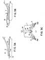
- a rivet or staple 15 emerging from the catheter 20may simply displace the leaflets 1,2 from the catheter tip 22 (as shown in Figure 2C) rather than successfully penetrate the leaflets.
- approaches that employ grasping the leafletsgenerally do so in a plane perpendicular to the catheter, and do not provide a sufficiently large and stable leaflet surface area through which a staple or a suture can be inserted.
- the present inventionprovides novel devices for minimally invasive methods to treat heart disease related to mitral valve regurgitation occurring in the context of cardiac valve prolapse as defined in claim 1.
- the present inventionallows for independent capture and repositioning of mitral leaflets regardless of whether they are aligned, and provides a stabilized large leaflet surface area through which sutures, staples, rivets and the like may be inserted.
- Use of a novel percutaneous catheter and other novel devices disclosed hereinenables therapeutic maneuvers that do not require opening the chest or heart, however the present invention is not limited to percutaneous approaches.
- the several specific preferred embodiments of the present invention referring to the invention's applicability to the mitral valveare meant in no way to be limiting. It will be readily appreciated that the present invention may additionally be effectively applied to leaflets of the tricuspid valve.
- the present inventionprovides a device as defined in claim 1 for use in a method to repair a mitral valve, comprised of a catheter assembly for delivering in a minimally invasive manner a pair of maneuverable grasping elements that are independently translatable through the catheter assembly to a position near the mitral valve.
- the grasping elementsare reversibly and radially extendable from the catheter assembly so as to capture and stabilize portions of two valve leaflets in an apposed position so that a fastening mechanism (e.g. , a staple, rivet or the like) which is also translated through the catheter assembly may be used to affix portions of the anterior and posterior leaflets to one another.
- a fastening mechanisme.g. , a staple, rivet or the like
- the catheter assemblycomprises a single catheter, that may be substantially straight for an antegrade approach, or alternatively may have a curved distal end so as to enable valve access retrograde via the aorta.
- Shape memory materialssuch as nickel titanium (e.g ., NITINOLTM www.nitinol.com) may be used to manufacture several components of the present invention, including the curved distal end of the catheter assembly.
- the fastening mechanism and grasping elementsare optionally composed of shape memory material as well.
- the catheter assemblycomprises a pair of slidably linked catheters, each of which is responsible for delivering a grasping element to the mitral valve region.
- the fastening mechanismis radially extendable and disengagable from the catheter assembly through at least one side port of the catheter assembly. Described below is a mechanism by which the fastening mechanism may be disengaged from the catheter assembly after insertion through the leaflets, which occurs, significantly, without displacing the captured leaflets in a direction away from the catheter assembly and each other.
- the grasping elementsextend from the distal end of the catheter assembly with reverse deformation so as to clip the ventricular side of the valve leaflets.
- the grasping elementsextend from side ports in the catheter assembly and are steered so as to be able to grasp the atrial sides of the leaflets.
- two pairs of grasping elementsare employed to grasp both sides of both the posterior and anterior leaflets.
- Various embodiments of the grasping elementsare described below, including clip-like configurations and embodiments having operable jaws disposed at the ends of each grasping element.
- each grasping elementis triggered by sensors for detecting contact and/or proximity of the leaflet to be grasped to the grasping element1.
- External or internal cardiac imaging of the region of the mitral valvemay be employed to facilitate proper positioning of the grasping elements and/or monitoring of effectiveness of the procedure.
- This imagingcan alternatively be achieved through the use of ultrasound, magnetic resonance or fiber optics.
- Devices in accordance with the present inventionare characterized in that they permit the anterior and posterior leaflets to be separately grasped and independently translated along an axis of a catheter assembly until leaflet apposition is achieved for the purpose of fastening the leaflets to one another.
- Use of the devicesis not, however, limited to the mitral valve, as use on the tricuspid or any other cardiac valve will be readily appreciated by artisans.
- a percutaneous catheter 20is inserted through the interatrial septum into the left atrium 7 and then between the mitral leaflets (only anterior leaflet 1 shown) to the left ventricle 4 to a position adjacent leaflet 1 that is to be repositioned.
- the mitral leafletsonly anterior leaflet 1 shown
- the grasping element 24is composed of a shape memory material that has been pre-formed to have a shape and dimensions appropriate for clipping or compressing leaflet 1 against the external surface 23 of the catheter 20, such as shown in Figure 3B.
- the grasping element 24When the grasping element 24 is extruded from the tip 22, the element takes its pre-formed shape, which as depicted can be a reverse curve 25 that results in a clip-like structure on the ventricular surface 3 of leaflet 1.
- the manufacturing of biocompatible shape memory componentsis well described in the art, thus will not be recited here.
- Figure 3Cdepicts a view of the mitral valve looking down onto the upper surface of the anterior mitral leaflet. Note that the device operates in this case in the gap between the chordal connections 5 to each side of the leaflet.
- the grasping element 24has preferably two side arms 26 that extend to either side of the catheter axis in a V-shaped or similar configuration having a separation there between sufficient to allow a staple or rivet 30 to be inserted through the leaflet unopposed by the grasping element .
- This designprovides greater stability than a single point of leaflet contact, and allows a staple or rivet 30 to be inserted between the side arms 26 of the grasping element without the leaflet being displaced in the process.
- the designalso provides a relatively large, stabilized leaflet surface area against the external surface 23 of the catheter 20 and minimizes leaflet displacement during the process of staple or rivet fastening.
- An alternative embodimentsincludes the use of auxiliary suctioning ports on the catheter 20 to assist in the grasping process; these may be independently translatable.
- alternative embodiments of the grasping elementsare each comprised of a control rod 34 having a steerable distal end 33, upon which is disposed a grabbing tool 32.
- a variety of mechanisms for steering percutaneous surgical instrumentsare known to artisans and may be employed in steering the distal end 33 so as to position the grabbing tool 32 adjacent a portion of the atrial surface 35 to be grasped.
- Each distal end 33is extended and retracted through a side port 37 or groove in catheter 20.
- the grabbing tool 32in one embodiment, has two pincer-like jaws 36 (two versions of which are shown in Figures 4B, 4C) that grasp the atrial surface 35 of the leaflet.
- One experienced in the artwill recognize that a variety of other mechanisms currently available can be used as grabbing tools as an alternative to the jaws 36.
- One such alternativeincludes the use of suction tips combined with pincers, a design serving to improve leaflet-catheter contact but not requiring as high a suction rate such as needed to grasp both leaflets simultaneously, the suction herein being used only for fine positioning and alignment.
- more than one grasping elementis employed to grasp the atrial surface of the leaflet.
- Multiple grasping elementsextend in a similar direction away from the catheter to allow grasping of a selected axial length of the atrial surface. For example, there could be two grasping elements pointing to one side of the valve, and two to the other, thus stabilizing a square or rectangular portion of the leaflet surface.
- a single catheter 20has been used to deliver and position the grasping elements to positions adjacent the ventricular or atrial surfaces of the leaflets.
- four independent grasping elementsare used to grasp both surfaces of both leaflets, two elements per leaflet on opposite sides. This configuration provides the greatest flexibility in repositioning the leaflets into apposition and stabilizing them through the fastening step.
- the grasping elements 24may be delivered independently through separate but linked catheters 21,21'.
- the catheters 21,21'are linked, for example, by a tongue and groove configuration, that allows them to move in a common plane. Translating the catheters achieves the desired leaflet 1,2 approximation after the grasping step.
- Each of the catheters 21,21' in the catheter assemblyhas opening that together form a channel 28 through which the staple or rivet 30 is extended when the leaflets are repositioned in apposition.
- the staples or rivets 30in one embodiment are composed of shape memory material and dimensioned to allow translation through the catheter 20 lumen and rapid expansion, effecting insertion and leaflet fastening, when the staples or rivets 30 reach an orifice 31 in the side wall of the catheter.
- the staples or rivets 30are translated down the catheter 20 lumen by a plunger 29 until the orifice 31 is encountered.
- the staples or rivets 30then emerge and pierce both leaflets, which have been previously stabilized by the grasping elements 24 described above.
- the shape memory staple or rivetemerges on the side of the leaflet opposite that of the catheter, and curves back to form a staple. Two or more such staples or rivets may be inserted at the same site, each facing in a different direction.
- retractable door 40 in the side wall of the cathetercan then be opened to disengage the catheter from the staples and move it to another site, so the leaflets can also be fastened together at additional locations to stabilize the repair, if necessary.
- the shape memory devicecontinues to compress the leaflets together until an effective seal is formed.
- FIGs 5B through 5Eillustrate the sequence of maneuvers that achieve leaflet fastening at more than one site.
- the cardiac valveis viewed from side to side as if looking down on its anterior leaflet 1 (as in the orientation shown in Figure 3C.)
- Catheter 20is depicted as entering from an atrial route, although the same process can be practiced with the catheter entering retrograde from the aorta.
- staples or rivets 30have been inserted through the orifice 31 in the catheter that allows their extrusion into the leaflets.
- a portion 40 of the side wall of the catheteris retracted into the catheter lumen, activated by a wire or other connection to the catheter controls outside the patient.
- This stepopens a hole 41 in the side of the catheter.
- the catheteris then disengaged from the staple or riveting device, and translated parallel to the catheter axis 37.
- Figure 5Dshows the catheter translated to a position closer to one side of the leaflet.
- Figure 5Eshows the retractable catheter wall portion 40 replaced to re-form the piercing orifice 31 and allow fastening of the leaflets at another site. This can increase the efficacy of repair, as necessary, depending upon the precise geometry of the separated and regurgitant leaflets.
- This approachcan be practiced with the linked sub-catheters shown in Figures 3D and 3E as well, using retractable wall portions for each sub-catheter. Retractable portions of the catheter side walls may be placed on both sides of the catheter to allow translation in either direction.
- the disengaged catheter 20may also be translated parallel to its axis 37 to insert additional staples at more than one site along the central axis of the left ventricle, which is parallel to the initial catheter axis.
- an alternative embodimentinserts the catheter 20 retrograde into the left ventricle 4 through the aorta.
- the catheteris shaped or steered to curve back toward the mitral leaflet tips using shape memory materials or other steering mechanisms known in the art.
- An advantage of the present inventionis the need for only a single catheter assembly due to the novel leaflet grasping elements, as opposed to catheters coming from both aortic and artial routes.
- Leaflet-grasping elements, after positioning,are then applied to the distal leaflet tips.
- the grasping elements 24are extended forward from the catheter onto the ventricular sides of the leaflet to surround the leaflet between catheter and clip. This forward grasping may be achieved through a number of mechanisms.
- the grasping elements 24may be comprised of preformed shape memory material that compresses the leaflets upon extension from side ports in the catheter.
- the grasping elementsmay be comprised of more rigid members that are hinged upon control rods within a sock-like component that, when extended beyond the hinge point, urges the members back towards the catheter, encompassing a portion of the leaflet therebetween.
- the entire processis preferably performed under the guidance of an imaging technique, such as echocardiography.
- an imaging techniquesuch as echocardiography.
- Such guidancemay be achieved using near infrared visualization (such as described in U.S. patent 6,178,346 ), with an intracardiac magnetic resonance imaging coil, or by transthoracic real-time three-dimensional echocardiographic imaging.
- Ultrasound imagingmay be performed from the chest surface, esophagus, or within the heart, using an independent intracardiac echo (ICE) catheter (commercially available) within the adjacent right ventricular outflow tract, or an ultrasound transducer within the left ventricle itself, built into the catheter 20.
- ICEintracardiac echo
- This arrangementallows an imaging element 50 to be maneuvered via the catheter to provide high-resolution images of the cardiac valve during the procedure, while also displaying the mitral leaflets and regurgitant jet.
- a two-dimensional matrix array of piezoelectric crystalsmay be used, or a linear phased array may be rapidly rotated to produce a three-dimensional image.
- the imagingmay also be employed to confirm catheter contact with the leaflets and trigger the grasping step.
- the imaging elementcan be comprised of a simple piezoelectric crystal or optical coherence device that senses the motion of the leaflets. When the leaflet approaches the catheter in systole, the device outputs a triggering signal confirmable manually on an output display device. Once confirmed, the following triggering signal is output to a mechanism to translate the grasping element rapidly down the lumen to assume the retroflexing shape thereby effecting capture.
- leaflet captureis effected by rapidly advancing a magnetic rod through the bore of the catheter to a position wherein the distal end of the extruded or extended grasping element, which in this embodiment is composed at least in part of a ferromagnetic material, is rapidly attracted toward the magnetic rod and the catheter.
- a jointed rodis rapidly advanced so as to retroflex the grasping element against the leaflet.
- Both catheter introduction routesmay also be practiced using a stabilizing catheter extension 60 advanced to the left ventricle apex 62, as shown in Figures 7A and 7B.
- a stabilizing catheter extension 60advanced to the left ventricle apex 62, as shown in Figures 7A and 7B.
- the contact element 64may be made of shape memory elastic material which, when extruded from the catheter, forms a curving or tined contacting structure.
- Catheter 20may then be translated along this wire to position the grasping elements 24,32 optimally in the region of the leaflet.
- the stabilizing catheter extension 60is in continuity with the fastening catheter 20, while for retrograde aortic routes ( Figure 7B), the fastening catheter 20 emerges from an introducer catheter 64, and is steered toward the leaflets.
- the fastening catheter 20is passed through a port in the introducer catheter 64, either directly or through a directing arm that may have an occlusive rubber seal.
- the introducer catheter 64is stabilized by the curving contact element 64 extending beyond the catheter tip and shaped to maintain contact with the ventricular apex.
- the contact element 64may alternatively be comprised of several elements composed of shape memory elastic material which, when extended from the catheter itself, form curving or tined contacting elements that may contact other portions of the interior of the cavity.
- the stabilizing mechanism described hereis merely illustrative.
- the stabilizing mechanismis not limited to a wire or shape memory materials, nor is it limited to a single extendable contact element.
- some embodimentsmay employ a plurality of stabilizing legs or telescoping extensions to contact inner left ventricle at numerous points around its circumference.
- the device of this inventionmay also be practiced effectively in conjunction with procedures that assist in approximating the leaflets by inserting a mitral annular ring percutaneously.
- a mitral annular ringpercutaneously.
- Such a deviceis inserted into the coronary sinus, a vein that encircles the mitral valve at the level of its annulus (the insertion of the leaflets onto the rest of the heart). Reducing annular size also helps in approximating the leaflets to achieve optimal repair.
- This combination of techniques utilizing the device of the present inventionwould provide a completely percutaneous approach to comprehensive repair of mitral valve prolapse and degenerative mitral regurgitation.
- the present inventioncan also be used to treat ischemic mitral regurgitation in dilated hearts to reduce volume overload and prevent heart failure. Many of the more severe regurgitant lesions in such patients also involve malcoaption of non-opposed leaftet portions that can be repaired by this device.
- the present inventionmay be used with methods for reducing the tension on the leaflets to be so repaired, including percutaneous annular ring reductions and methods for reducing ventricular size. It can also be used to appose and link any two scallops of the posterior leaflet that may be malaligned or prolapse relative to each other, causing regurgitation.
Landscapes
- Health & Medical Sciences (AREA)
- Life Sciences & Earth Sciences (AREA)
- Surgery (AREA)
- Molecular Biology (AREA)
- General Health & Medical Sciences (AREA)
- Biomedical Technology (AREA)
- Heart & Thoracic Surgery (AREA)
- Medical Informatics (AREA)
- Nuclear Medicine, Radiotherapy & Molecular Imaging (AREA)
- Animal Behavior & Ethology (AREA)
- Engineering & Computer Science (AREA)
- Public Health (AREA)
- Veterinary Medicine (AREA)
- Surgical Instruments (AREA)
- Prostheses (AREA)
- Medicines That Contain Protein Lipid Enzymes And Other Medicines (AREA)
- Pharmaceuticals Containing Other Organic And Inorganic Compounds (AREA)
- Materials For Medical Uses (AREA)
- Medicinal Preparation (AREA)
Abstract
Description
- The present invention relates generally to devices (i.e., articles of manufacture, apparatus, systems, instruments) for treating heart disease and, in particular, to devices for minimally invasive repair of atrioventricular valve regurgitation (MR) occurring in the context of mitral valve prolapse (MVP), flail mitral valve, and/or ischemic MR.
- A mitral valve,such as shown inFigure 1A, including an
anterior leaflet 1 and aposterior leaflet 2, is the inlet valve to the main heart pumping chamber (left ventricle4). The mitral valve is forced to close when theventricle 4 contracts, preventing backward flow of blood. To ensure that this valve does not prolapse backward (into left atrium 7) when the heart contracts,leaflets tendinous chords 5 anchored to the posterior wall of theheart 6. The leaflets normally meet or coapt so that their tips are juxtaposed, along with up to one-third of their lengths, forming aneffective seal 8 to prevent MR. In a variety of diseases, however, the leaflets fail to meet properly due to leaflet elongation or elongation or rupture of thechords 5. As shown inFigure 1B, one or more leaflet portions10 may then prolapse into theleft atrium 7, reducing coaptation and creating a gap between theleaflets arrows 9.). Such regurgitation can produce heart failure, rhythm disorders, sudden death, and a predisposition to lethal heart valve infections. Therapy has until now required open-heart surgery to replace the valve or repair it by approximating leaflet tips. - Alfieri,et. al, have described a possibly minimally invasive repair mechanism. As shown inFigure 1C, a
suture 12 may be placed between the tips of theleaflets openings 14, one on each side of thesuture 12 position. Such an orifice does not materially obstruct inflow of blood into the left ventricle. - Several approaches have been proposed to practice this repair in a minimally invasive manner. Specifically, Grimes (
U.S. patent 6,312,447 ) teaches that a catheter, advanced across the interatrial septum into the left atrium, can grasp the leaflet tips using a suction apparatus at the end of the catheter. A fastener such as a staple or shape memory rivet is then inserted into the leaflet tips to effect the edge-to-edge closure repair. International patent publication WO 00/60995International patent publication WO 99/13777 - US patent application publication
US 2002/0013571 discloses methods and devices for grasping and optional repositioning and fixation of the valve leaflets to treat cardiac valve regurgitation, particularly mitral valve regurgitation. US patent 6,165,183 discloses an approach to mitral or tricuspid valve repair involving the performance of an edge-to-edge fastening/securing of opposing heart valve leaflets through a catheter entering the heart.- Previous approaches employing suctioning and/or suturing of leaflet tips suffer from a number of common limitations. First and foremost, as shown inFigure 2A, in patients with sufficient MR to warrant such procedure, the
leaflets single device 22 alone at the tip of acatheter 20, or multiple devices at a single location along the catheter center axis11, to bring the leaflet tips, at spatiallydistinct positions leaflet surfaces staple 15 emerging from thecatheter 20 may simply displace theleaflets - Thus, what is needed is a percutaneous mitral (or tricuspid) valve repair system that can overcome these and other limitations of the prior art. A single device accomplishing all of the above objectives and others is highly desirable.
- The present invention provides novel devices for minimally invasive methods to treat heart disease related to mitral valve regurgitation occurring in the context of cardiac valve prolapse as defined in
claim 1. The present invention allows for independent capture and repositioning of mitral leaflets regardless of whether they are aligned, and provides a stabilized large leaflet surface area through which sutures, staples, rivets and the like may be inserted. Use of a novel percutaneous catheter and other novel devices disclosed herein enables therapeutic maneuvers that do not require opening the chest or heart, however the present invention is not limited to percutaneous approaches. In the description that follows, the several specific preferred embodiments of the present invention referring to the invention's applicability to the mitral valve are meant in no way to be limiting. It will be readily appreciated that the present invention may additionally be effectively applied to leaflets of the tricuspid valve. - In a first aspect, the present invention provides a device as defined in
claim 1 for use in a method to repair a mitral valve, comprised of a catheter assembly for delivering in a minimally invasive manner a pair of maneuverable grasping elements that are independently translatable through the catheter assembly to a position near the mitral valve. The grasping elements are reversibly and radially extendable from the catheter assembly so as to capture and stabilize portions of two valve leaflets in an apposed position so that a fastening mechanism (e.g., a staple, rivet or the like) which is also translated through the catheter assembly may be used to affix portions of the anterior and posterior leaflets to one another. - In one embodiment, the catheter assembly comprises a single catheter, that may be substantially straight for an antegrade approach, or alternatively may have a curved distal end so as to enable valve access retrograde via the aorta. Shape memory materials, such as nickel titanium (e.g., NITINOL™ www.nitinol.com) may be used to manufacture several components of the present invention, including the curved distal end of the catheter assembly. The fastening mechanism and grasping elements are optionally composed of shape memory material as well.
- In another embodiment, the catheter assembly comprises a pair of slidably linked catheters, each of which is responsible for delivering a grasping element to the mitral valve region.
- The fastening mechanism is radially extendable and disengagable from the catheter assembly through at least one side port of the catheter assembly. Described below is a mechanism by which the fastening mechanism may be disengaged from the catheter assembly after insertion through the leaflets, which occurs, significantly, without displacing the captured leaflets in a direction away from the catheter assembly and each other.
- In one embodiment, the grasping elements extend from the distal end of the catheter assembly with reverse deformation so as to clip the ventricular side of the valve leaflets. In an alternative, but not mutually exclusive embodiment, the grasping elements extend from side ports in the catheter assembly and are steered so as to be able to grasp the atrial sides of the leaflets. In a preferred embodiment, two pairs of grasping elements are employed to grasp both sides of both the posterior and anterior leaflets. Various embodiments of the grasping elements are described below, including clip-like configurations and embodiments having operable jaws disposed at the ends of each grasping element.
- In certain embodiments, the operation of each grasping element is triggered by sensors for detecting contact and/or proximity of the leaflet to be grasped to the grasping element1.
- External or internal cardiac imaging of the region of the mitral valve may be employed to facilitate proper positioning of the grasping elements and/or monitoring of effectiveness of the procedure. This imaging can alternatively be achieved through the use of ultrasound, magnetic resonance or fiber optics.
- For a better understanding of the present invention, reference is made to the accompanying drawing and detailed description. The scope of the present invention will be pointed out in the appended claims.
- The advantages of the present invention will be apparent in the following detailed description of the illustrative embodiments thereof, which is to be read in connection with the accompanying drawing, wherein:
- Figures 1A-1C are illustrations of a portion of a human heart showing normal, prolapsed and repaired mitral leaflet closure, diagrammed in a long-axis view of the left ventricle, as would be viewable by ultrasound imaging;
- Figure 1D is an illustration of the mitral leaflets after repair, as viewable from the left atrial perspective with the valve open when the heart relaxes;
- Figure 2A is a side view illustration of a cardiac valve demonstrating a limitation of a prior art catheter suctioning approach to grasping leaflets at different positions along a catheter due to prolapse;
- Figures 2B-2C are side view illustrations of a cardiac valve demonstrating the displacement of mitral leaflets encountered by prior art approaches to valve stapling;
- Figures 3A-3B are side view illustrations of a cardiac leaflet being grasped on its ventricular surface by a grasping element in accordance with one embodiment of the present invention;
- Figure 3C is an illustration of a grasping element in accordance with the present invention showing two side-arms for stabilizing a portion of the leaflet surface so that a staple or rivet can be inserted therebetween, as viewed from above, looking down onto the upper surface of the anterior mitral leaflet;
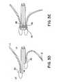
- Figures 3D-3E are side view illustrations of a catheter assembly comprised of two linked catheters that independently translate grasped leaflets into apposition for fastening;
- Figure 4A is a side view illustration of a mechanism for grasping the atrial surface of the leaflets, with independent translation of two grabbing elements to approximate the leaflets;
- Figures 4B,4C are schematic illustrations of serrated and smooth pincer-like grabbing tools disposed at the end of certain embodiments of the grasping elements;
- Figure 5A is a schematic illustration of a mechanism for inserting staples or rivets through an orifice in the catheter to fasten leaflets that have been approximated into apposition;
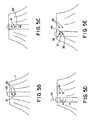
- Figures 5B-5E are illustrations of operational steps for using a mechanism to disengage a staple from the catheter delivering it to the leaflet vicinity;
- Figure 6A is an illustration of a retrograde catheter insertion with grasping elements grasping the ventricular surfaces of the leaflets;
- Figure 6B is an illustration of a retrograde catheter insertion with grasping elements grasping both atrial and ventricular surfaces of the leaflets under imaging guidance;
- Figures 7A-7B are illustrations of embodiments of catheter stabilization mechanisms in accordance with the present invention.
- Preferred embodiments of the present invention will now be described with reference to the several figures of the drawing.
- Numerous embodiments of the present invention will now be described in the context of mitral valve prolapse. Devices in accordance with the present invention are characterized in that they permit the anterior and posterior leaflets to be separately grasped and independently translated along an axis of a catheter assembly until leaflet apposition is achieved for the purpose of fastening the leaflets to one another. Use of the devices is not, however, limited to the mitral valve, as use on the tricuspid or any other cardiac valve will be readily appreciated by artisans.
- With reference toFigure 3A, in one embodiment of the present invention a
percutaneous catheter 20 is inserted through the interatrial septum into theleft atrium 7 and then between the mitral leaflets (onlyanterior leaflet 1 shown) to theleft ventricle 4 to a positionadjacent leaflet 1 that is to be repositioned. Throughcatheter 20 at least oneleaflet grasping element 24 can be reversibly extended from thecatheter tip 22. The graspingelement 24 is composed of a shape memory material that has been pre-formed to have a shape and dimensions appropriate for clipping or compressingleaflet 1 against theexternal surface 23 of thecatheter 20, such as shown inFigure 3B. When the graspingelement 24 is extruded from thetip 22, the element takes its pre-formed shape, which as depicted can be areverse curve 25 that results in a clip-like structure on theventricular surface 3 ofleaflet 1. The manufacturing of biocompatible shape memory components is well described in the art, thus will not be recited here. - Figure 3C depicts a view of the mitral valve looking down onto the upper surface of the anterior mitral leaflet. Note that the device operates in this case in the gap between the
chordal connections 5 to each side of the leaflet. In a preferred embodiment, the graspingelement 24 has preferably twoside arms 26 that extend to either side of the catheter axis in a V-shaped or similar configuration having a separation there between sufficient to allow a staple or rivet30 to be inserted through the leaflet unopposed by the grasping element . This design provides greater stability than a single point of leaflet contact, and allows a staple or rivet30 to be inserted between theside arms 26 of the grasping element without the leaflet being displaced in the process. The design also provides a relatively large, stabilized leaflet surface area against theexternal surface 23 of thecatheter 20 and minimizes leaflet displacement during the process of staple or rivet fastening. An alternative embodiments includes the use of auxiliary suctioning ports on thecatheter 20 to assist in the grasping process; these may be independently translatable. - With reference toFigure 4A, alternative embodiments of the grasping elements are each comprised of a
control rod 34 having a steerabledistal end 33, upon which is disposed a grabbingtool 32. A variety of mechanisms for steering percutaneous surgical instruments are known to artisans and may be employed in steering thedistal end 33 so as to position the grabbingtool 32 adjacent a portion of theatrial surface 35 to be grasped. Eachdistal end 33 is extended and retracted through aside port 37 or groove incatheter 20. The grabbingtool 32, in one embodiment, has two pincer-like jaws36 (two versions of which are shown inFigures 4B, 4C) that grasp theatrial surface 35 of the leaflet. One experienced in the art will recognize that a variety of other mechanisms currently available can be used as grabbing tools as an alternative to thejaws 36. One such alternative includes the use of suction tips combined with pincers, a design serving to improve leaflet-catheter contact but not requiring as high a suction rate such as needed to grasp both leaflets simultaneously, the suction herein being used only for fine positioning and alignment. - In another embodiment (not shown), more than one grasping element is employed to grasp the atrial surface of the leaflet. Multiple grasping elements extend in a similar direction away from the catheter to allow grasping of a selected axial length of the atrial surface. For example, there could be two grasping elements pointing to one side of the valve, and two to the other, thus stabilizing a square or rectangular portion of the leaflet surface.
- In the embodiments described to this point, a
single catheter 20 has been used to deliver and position the grasping elements to positions adjacent the ventricular or atrial surfaces of the leaflets. In a preferred embodiment, four independent grasping elements are used to grasp both surfaces of both leaflets, two elements per leaflet on opposite sides. This configuration provides the greatest flexibility in repositioning the leaflets into apposition and stabilizing them through the fastening step. - With reference to the alternative embodiment shown inFigures 3D and3E, the grasping
elements 24 may be delivered independently through separate but linkedcatheters 21,21'. Thecatheters 21,21' are linked, for example, by a tongue and groove configuration, that allows them to move in a common plane. Translating the catheters achieves the desiredleaflet catheters 21,21' in the catheter assembly has opening that together form achannel 28 through which the staple or rivet 30 is extended when the leaflets are repositioned in apposition. - As shown inFigure 5A, once the
leaflets catheter 20 lumen and rapid expansion, effecting insertion and leaflet fastening, when the staples or rivets30 reach anorifice 31 in the side wall of the catheter. The staples or rivets30 are translated down thecatheter 20 lumen by aplunger 29 until theorifice 31 is encountered. The staples or rivets30 then emerge and pierce both leaflets, which have been previously stabilized by thegrasping elements 24 described above. The shape memory staple or rivet emerges on the side of the leaflet opposite that of the catheter, and curves back to form a staple. Two or more such staples or rivets may be inserted at the same site, each facing in a different direction. - As shown inFigure 5B,
retractable door 40 in the side wall of the catheter can then be opened to disengage the catheter from the staples and move it to another site, so the leaflets can also be fastened together at additional locations to stabilize the repair, if necessary. After the catheter has been disengaged, the shape memory device continues to compress the leaflets together until an effective seal is formed. - Figures 5B through5E illustrate the sequence of maneuvers that achieve leaflet fastening at more than one site. In these figures, the cardiac valve is viewed from side to side as if looking down on its anterior leaflet1 (as in the orientation shown inFigure 3C.)
Catheter 20 is depicted as entering from an atrial route, although the same process can be practiced with the catheter entering retrograde from the aorta. InFigure 5B, staples or rivets30 have been inserted through theorifice 31 in the catheter that allows their extrusion into the leaflets. Turning toFigure 5C, aportion 40 of the side wall of the catheter is retracted into the catheter lumen, activated by a wire or other connection to the catheter controls outside the patient. This step opens ahole 41 in the side of the catheter. The catheter is then disengaged from the staple or riveting device, and translated parallel to thecatheter axis 37. Figure 5D shows the catheter translated to a position closer to one side of the leaflet.Figure 5E shows the retractablecatheter wall portion 40 replaced to re-form the piercingorifice 31 and allow fastening of the leaflets at another site. This can increase the efficacy of repair, as necessary, depending upon the precise geometry of the separated and regurgitant leaflets. This approach can be practiced with the linked sub-catheters shown inFigures 3D and3E as well, using retractable wall portions for each sub-catheter. Retractable portions of the catheter side walls may be placed on both sides of the catheter to allow translation in either direction. After one staple has been placed, with slight adjustment of the angle of catheter approach, thedisengaged catheter 20 may also be translated parallel to itsaxis 37 to insert additional staples at more than one site along the central axis of the left ventricle, which is parallel to the initial catheter axis. - With reference toFigures 6A, and6B, an alternative embodiment inserts the
catheter 20 retrograde into theleft ventricle 4 through the aorta. The catheter is shaped or steered to curve back toward the mitral leaflet tips using shape memory materials or other steering mechanisms known in the art. An advantage of the present invention is the need for only a single catheter assembly due to the novel leaflet grasping elements, as opposed to catheters coming from both aortic and artial routes. Leaflet-grasping elements, after positioning, are then applied to the distal leaflet tips. Thegrasping elements 24 are extended forward from the catheter onto the ventricular sides of the leaflet to surround the leaflet between catheter and clip. This forward grasping may be achieved through a number of mechanisms. For example, the graspingelements 24 may be comprised of preformed shape memory material that compresses the leaflets upon extension from side ports in the catheter. Alternatively, the grasping elements may be comprised of more rigid members that are hinged upon control rods within a sock-like component that, when extended beyond the hinge point, urges the members back towards the catheter, encompassing a portion of the leaflet therebetween. - With reference toFigure 6B, the entire process is preferably performed under the guidance of an imaging technique, such as echocardiography. Such guidance may be achieved using near infrared visualization (such as described in
U.S. patent 6,178,346 ), with an intracardiac magnetic resonance imaging coil, or by transthoracic real-time three-dimensional echocardiographic imaging. Ultrasound imaging may be performed from the chest surface, esophagus, or within the heart, using an independent intracardiac echo (ICE) catheter (commercially available) within the adjacent right ventricular outflow tract, or an ultrasound transducer within the left ventricle itself, built into thecatheter 20. This arrangement allows animaging element 50 to be maneuvered via the catheter to provide high-resolution images of the cardiac valve during the procedure, while also displaying the mitral leaflets and regurgitant jet. To produce a three-dimensional ultrasound image, a two-dimensional matrix array of piezoelectric crystals may be used, or a linear phased array may be rapidly rotated to produce a three-dimensional image. - The imaging may also be employed to confirm catheter contact with the leaflets and trigger the grasping step. The imaging element can be comprised of a simple piezoelectric crystal or optical coherence device that senses the motion of the leaflets. When the leaflet approaches the catheter in systole, the device outputs a triggering signal confirmable manually on an output display device. Once confirmed, the following triggering signal is output to a mechanism to translate the grasping element rapidly down the lumen to assume the retroflexing shape thereby effecting capture. In another embodiment, leaflet capture is effected by rapidly advancing a magnetic rod through the bore of the catheter to a position wherein the distal end of the extruded or extended grasping element, which in this embodiment is composed at least in part of a ferromagnetic material, is rapidly attracted toward the magnetic rod and the catheter. In yet another embodiment, a jointed rod is rapidly advanced so as to retroflex the grasping element against the leaflet.
- Both catheter introduction routes (through the mitral valve or the aorta) may also be practiced using a stabilizing
catheter extension 60 advanced to theleft ventricle apex 62, as shown inFigures 7A and7B. From theextension 60 is extended acurving contact element 64 shaped to maintain contact with the apex62. Thecontact element 64 may be made of shape memory elastic material which, when extruded from the catheter, forms a curving or tined contacting structure.Catheter 20 may then be translated along this wire to position thegrasping elements catheter extension 60 is in continuity with thefastening catheter 20, while for retrograde aortic routes(Figure 7B), thefastening catheter 20 emerges from anintroducer catheter 64, and is steered toward the leaflets. Thefastening catheter 20 is passed through a port in theintroducer catheter 64, either directly or through a directing arm that may have an occlusive rubber seal. Theintroducer catheter 64 is stabilized by the curvingcontact element 64 extending beyond the catheter tip and shaped to maintain contact with the ventricular apex. Thecontact element 64 may alternatively be comprised of several elements composed of shape memory elastic material which, when extended from the catheter itself, form curving or tined contacting elements that may contact other portions of the interior of the cavity. - It is worth noting that the stabilizing mechanism described here is merely illustrative. The stabilizing mechanism is not limited to a wire or shape memory materials, nor is it limited to a single extendable contact element. For example, some embodiments may employ a plurality of stabilizing legs or telescoping extensions to contact inner left ventricle at numerous points around its circumference.
- The device of this invention may also be practiced effectively in conjunction with procedures that assist in approximating the leaflets by inserting a mitral annular ring percutaneously. Such a device is inserted into the coronary sinus, a vein that encircles the mitral valve at the level of its annulus (the insertion of the leaflets onto the rest of the heart). Reducing annular size also helps in approximating the leaflets to achieve optimal repair. This combination of techniques utilizing the device of the present invention would provide a completely percutaneous approach to comprehensive repair of mitral valve prolapse and degenerative mitral regurgitation.
- The present invention can also be used to treat ischemic mitral regurgitation in dilated hearts to reduce volume overload and prevent heart failure. Many of the more severe regurgitant lesions in such patients also involve malcoaption of non-opposed leaftet portions that can be repaired by this device. The present invention may be used with methods for reducing the tension on the leaflets to be so repaired, including percutaneous annular ring reductions and methods for reducing ventricular size. It can also be used to appose and link any two scallops of the posterior leaflet that may be malaligned or prolapse relative to each other, causing regurgitation.
- While the foregoing specification has been described with regard to certain preferred embodiments, and many details have been set forth for the purpose of illustration, it will be apparent to those skilled in the art, that without departing from the spirit and scope of the invention, the invention may be subject to various modifications and additional embodiments, and that certain of the details described herein can be varied considerably without departing from the basic principles of the invention. Such modifications and additional embodiments are also intended to fall within the scope of the invention as defined in appended claims.
Claims (17)
- A device for repairing a cardiac valve, comprising:a catheter assembly (20, 21, 21') configured to pass from a remote vasculature of a patient to a position within the heart adjacent the cardiac valve;at least two maneuverable grasping elements (24, 32) independently translatable through the catheter assembly, the grasping elements being reversibly and radially extendable from the catheter assembly to capture and reposition portions of at least two valve leaflets (1, 2) into an apposed position; anda fastening mechanism (30) translatable through the catheter assembly to secure the stabilized portions of the two valve leaflets,wherein the fastening mechanism is radially extendable and disengagable from the catheter assembly through at least one side port (31, 41) of the catheter assembly.
- The device according to claim 1, wherein the catheter assembly (20, 21, 21') comprises a single catheter having a curved distal end so as to enable valve access retrograde via the aorta.
- The device according to claim 2, wherein the distal end is composed at least in part of a shape memory material.
- The device according to claim 1, wherein the catheter assembly (20, 21, 21') is comprised of a pair of slidably linked catheters, one of the grasping elements (24, 32) being disposed in each catheter, and wherein each catheter includes at least one side port (31, 41) through which the fastening mechanism (30) is extendable and disengagable from the catheter assembly.
- The device according to claim 1, wherein the fastening mechanism (30) comprises a staple or rivet insertable through each of the captured leaflet portions without displacing the leaflets (1, 2).
- The device according to claim 1, wherein the fastening mechanism (30) is composed at least in part of a shape memory material.
- The device according to claim 1, further comprising a retractable portion of the catheter assembly (20, 21, 21') proximate the at least one side port (31, 41), in its retracted state creating a notch in the catheter assembly through which the fastening mechanism is disengagable from the catheter assembly.
- The device according to any of claims 1 to 7, wherein each of the grasping elements (24, 32) extends from the distal end of the catheter assembly (20, 21, 21') with reverse deformation so as to clip a ventricular surface (13) of one of the valve leaflets (1, 2).
- The device according to claim 8, further comprising:steerable grasping elements (24, 32, 33) independently translatable through the catheter assembly (20, 21, 21'), each grasping element reversibly and radially extendable from one of at least two opposed side ports (31, 41) in the catheter assembly with an adjustable deformation so as to grasp an atrial surface (35) of one of the valve leaflets (1, 2).
- The device according to claim 1, wherein each of the grasping elements (24, 32) extends from one of at least two opposed side ports (31, 41) in the catheter assembly (20, 21,21') with at least one of(a) a deformation so as to clip a ventricular surface (3) of one of the valve leaflets (1,2), or(b) an adjustable deformation so as to grasp an atrial surface (35) of the valve leaflets (1, 2).
- The device according to claim 1 or 10, further comprising a pair of operable jaws (36) disposed on each distal end of the grasping elements (24, 32).
- The device according to claim 1 or 10, further comprising a suction assembly disposed on each distal end of the grasping elements (24, 32).
- The device according to any of claims 1 to 12, further comprising an introducer catheter for advancing the catheter assembly (20, 21, 21') toward the cardiac valve.
- The device of claim 13, wherein the introducer catheter further comprises at least one of:a. a directing arm through which the catheter assembly (20, 21 21') is maneuverable to a position proximate the cardiac valve,b. a first arrangement configured to temporarily stabilize a position of the introducer catheter within the left ventricle (4), orc. a second arrangement comprising one or more contact elements reversibly extendable from the introducer catheter so as to contact an internal surface of the heart cavity at one or more points.
- The device according to claim 14, wherein the one or more contact elements are composed of shape memory elastic material.
- The device according to any of claims 1 to 15, further comprising an imaging device (50) oriented so as to image a region near the cardiac valve.
- The device according to claim 1, further comprising:a capture triggering mechanism including one or more sensors for detecting the position of the valve leaflets (1, 2) with respect to the grasping elements (24, 32), wherein the grasping elements extend in response to an indication that the leaflets are within a predetermined distance from the grasping elements.
Priority Applications (2)
| Application Number | Priority Date | Filing Date | Title |
|---|---|---|---|
| EP07122916.5AEP1917919B1 (en) | 2002-08-13 | 2003-08-13 | Cardiac devices for percutaneous repair of atrioventricular valves |
| EP10185283AEP2319427A2 (en) | 2002-08-13 | 2003-08-13 | Cardiac devices and methods for percutaneous repair of atrioventricular valves |
Applications Claiming Priority (3)
| Application Number | Priority Date | Filing Date | Title |
|---|---|---|---|
| US40307302P | 2002-08-13 | 2002-08-13 | |
| US403073P | 2002-08-13 | ||
| PCT/US2003/025521WO2004014282A2 (en) | 2002-08-13 | 2003-08-13 | Cardiac devices and methods for percutaneous repair of atrioventricular valves |
Related Child Applications (1)
| Application Number | Title | Priority Date | Filing Date |
|---|---|---|---|
| EP07122916.5ADivisionEP1917919B1 (en) | 2002-08-13 | 2003-08-13 | Cardiac devices for percutaneous repair of atrioventricular valves |
Publications (3)
| Publication Number | Publication Date |
|---|---|
| EP1534146A2 EP1534146A2 (en) | 2005-06-01 |
| EP1534146A4 EP1534146A4 (en) | 2005-11-09 |
| EP1534146B1true EP1534146B1 (en) | 2008-01-23 |
Family
ID=31715930
Family Applications (2)
| Application Number | Title | Priority Date | Filing Date |
|---|---|---|---|
| EP03785293AExpired - LifetimeEP1534146B1 (en) | 2002-08-13 | 2003-08-13 | Cardiac devices for percutaneous repair of atrioventricular valves |
| EP10185283AWithdrawnEP2319427A2 (en) | 2002-08-13 | 2003-08-13 | Cardiac devices and methods for percutaneous repair of atrioventricular valves |
Family Applications After (1)
| Application Number | Title | Priority Date | Filing Date |
|---|---|---|---|
| EP10185283AWithdrawnEP2319427A2 (en) | 2002-08-13 | 2003-08-13 | Cardiac devices and methods for percutaneous repair of atrioventricular valves |
Country Status (8)
| Country | Link |
|---|---|
| US (1) | US7559936B2 (en) |
| EP (2) | EP1534146B1 (en) |
| JP (1) | JP4929428B2 (en) |
| AT (1) | ATE384479T1 (en) |
| AU (1) | AU2003262683A1 (en) |
| CA (1) | CA2496007C (en) |
| DE (1) | DE60318861T2 (en) |
| WO (1) | WO2004014282A2 (en) |
Cited By (1)
| Publication number | Priority date | Publication date | Assignee | Title |
|---|---|---|---|---|
| DE102008013858A1 (en)* | 2008-03-12 | 2009-09-24 | Siemens Aktiengesellschaft | Catheter device and associated medical examination and treatment device |
Families Citing this family (256)
| Publication number | Priority date | Publication date | Assignee | Title |
|---|---|---|---|---|
| US6050936A (en) | 1997-01-02 | 2000-04-18 | Myocor, Inc. | Heart wall tension reduction apparatus |
| US6406420B1 (en) | 1997-01-02 | 2002-06-18 | Myocor, Inc. | Methods and devices for improving cardiac function in hearts |
| EP2133030A1 (en)* | 1997-06-27 | 2009-12-16 | The Trustees of Columbia University of the City of New York | Method and apparatus for circulatory valve repair |
| FR2768324B1 (en) | 1997-09-12 | 1999-12-10 | Jacques Seguin | SURGICAL INSTRUMENT FOR PERCUTANEOUSLY FIXING TWO AREAS OF SOFT TISSUE, NORMALLY MUTUALLY REMOTE, TO ONE ANOTHER |
| US6332893B1 (en)* | 1997-12-17 | 2001-12-25 | Myocor, Inc. | Valve to myocardium tension members device and method |
| US6260552B1 (en) | 1998-07-29 | 2001-07-17 | Myocor, Inc. | Transventricular implant tools and devices |
| US6752813B2 (en) | 1999-04-09 | 2004-06-22 | Evalve, Inc. | Methods and devices for capturing and fixing leaflets in valve repair |
| US8216256B2 (en) | 1999-04-09 | 2012-07-10 | Evalve, Inc. | Detachment mechanism for implantable fixation devices |
| US10327743B2 (en)* | 1999-04-09 | 2019-06-25 | Evalve, Inc. | Device and methods for endoscopic annuloplasty |
| US7811296B2 (en) | 1999-04-09 | 2010-10-12 | Evalve, Inc. | Fixation devices for variation in engagement of tissue |
| US7226467B2 (en) | 1999-04-09 | 2007-06-05 | Evalve, Inc. | Fixation device delivery catheter, systems and methods of use |
| AU770243B2 (en) | 1999-04-09 | 2004-02-19 | Evalve, Inc. | Methods and apparatus for cardiac valve repair |
| US20040044350A1 (en)* | 1999-04-09 | 2004-03-04 | Evalve, Inc. | Steerable access sheath and methods of use |
| US6440164B1 (en) | 1999-10-21 | 2002-08-27 | Scimed Life Systems, Inc. | Implantable prosthetic valve |
| EP1113497A3 (en)* | 1999-12-29 | 2006-01-25 | Texas Instruments Incorporated | Semiconductor package with conductor impedance selected during assembly |
| US6723038B1 (en) | 2000-10-06 | 2004-04-20 | Myocor, Inc. | Methods and devices for improving mitral valve function |
| US6602286B1 (en) | 2000-10-26 | 2003-08-05 | Ernst Peter Strecker | Implantable valve system |
| US6575971B2 (en)* | 2001-11-15 | 2003-06-10 | Quantum Cor, Inc. | Cardiac valve leaflet stapler device and methods thereof |
| US20030120341A1 (en)* | 2001-12-21 | 2003-06-26 | Hani Shennib | Devices and methods of repairing cardiac valves |
| US6764510B2 (en) | 2002-01-09 | 2004-07-20 | Myocor, Inc. | Devices and methods for heart valve treatment |
| US7048754B2 (en) | 2002-03-01 | 2006-05-23 | Evalve, Inc. | Suture fasteners and methods of use |
| US6752828B2 (en) | 2002-04-03 | 2004-06-22 | Scimed Life Systems, Inc. | Artificial valve |
| US7007698B2 (en) | 2002-04-03 | 2006-03-07 | Boston Scientific Corporation | Body lumen closure |
| AU2003248750A1 (en) | 2002-06-27 | 2004-01-19 | J. Luis Guerrero | Ventricular remodeling for artioventricular valve regurgitation |
| AU2003265354A1 (en) | 2002-08-01 | 2004-02-23 | The General Hospital Corporation | Cardiac devices and methods for minimally invasive repair of ischemic mitral regurgitation |
| US7087064B1 (en) | 2002-10-15 | 2006-08-08 | Advanced Cardiovascular Systems, Inc. | Apparatuses and methods for heart valve repair |
| AU2003285943B2 (en) | 2002-10-24 | 2008-08-21 | Boston Scientific Limited | Venous valve apparatus and method |
| US7112219B2 (en) | 2002-11-12 | 2006-09-26 | Myocor, Inc. | Devices and methods for heart valve treatment |
| US7247134B2 (en) | 2002-11-12 | 2007-07-24 | Myocor, Inc. | Devices and methods for heart valve treatment |
| US8187324B2 (en) | 2002-11-15 | 2012-05-29 | Advanced Cardiovascular Systems, Inc. | Telescoping apparatus for delivering and adjusting a medical device in a vessel |
| US7981152B1 (en) | 2004-12-10 | 2011-07-19 | Advanced Cardiovascular Systems, Inc. | Vascular delivery system for accessing and delivering devices into coronary sinus and other vascular sites |
| US7485143B2 (en) | 2002-11-15 | 2009-02-03 | Abbott Cardiovascular Systems Inc. | Apparatuses and methods for heart valve repair |
| US7404824B1 (en) | 2002-11-15 | 2008-07-29 | Advanced Cardiovascular Systems, Inc. | Valve aptation assist device |
| US7331972B1 (en) | 2002-11-15 | 2008-02-19 | Abbott Cardiovascular Systems Inc. | Heart valve chord cutter |
| US6945978B1 (en) | 2002-11-15 | 2005-09-20 | Advanced Cardiovascular Systems, Inc. | Heart valve catheter |
| US7335213B1 (en) | 2002-11-15 | 2008-02-26 | Abbott Cardiovascular Systems Inc. | Apparatus and methods for heart valve repair |
| US9149602B2 (en) | 2005-04-22 | 2015-10-06 | Advanced Cardiovascular Systems, Inc. | Dual needle delivery system |
| US6945957B2 (en) | 2002-12-30 | 2005-09-20 | Scimed Life Systems, Inc. | Valve treatment catheter and methods |
| US7257450B2 (en)* | 2003-02-13 | 2007-08-14 | Coaptus Medical Corporation | Systems and methods for securing cardiovascular tissue |
| US10631871B2 (en) | 2003-05-19 | 2020-04-28 | Evalve, Inc. | Fixation devices, systems and methods for engaging tissue |
| US7998112B2 (en) | 2003-09-30 | 2011-08-16 | Abbott Cardiovascular Systems Inc. | Deflectable catheter assembly and method of making same |
| US7854761B2 (en) | 2003-12-19 | 2010-12-21 | Boston Scientific Scimed, Inc. | Methods for venous valve replacement with a catheter |
| US8128681B2 (en) | 2003-12-19 | 2012-03-06 | Boston Scientific Scimed, Inc. | Venous valve apparatus, system, and method |
| JP2007535342A (en) | 2004-03-11 | 2007-12-06 | パーキュテイニアス カルディオバスキュラー ソリューションズ ピー・ティー・ワイ リミテッド | Percutaneous prosthetic heart valve |
| US20050240202A1 (en)* | 2004-04-21 | 2005-10-27 | Hani Shennib | Devices and methods of repairing cardiac valves |
| JP4774048B2 (en) | 2004-05-14 | 2011-09-14 | エヴァルヴ インコーポレイテッド | Locking mechanism of fixing device engaged with tissue and tissue engaging method |
| US7566343B2 (en) | 2004-09-02 | 2009-07-28 | Boston Scientific Scimed, Inc. | Cardiac valve, system, and method |
| US7704277B2 (en)* | 2004-09-14 | 2010-04-27 | Edwards Lifesciences Ag | Device and method for treatment of heart valve regurgitation |
| WO2006037073A2 (en)* | 2004-09-27 | 2006-04-06 | Evalve, Inc. | Methods and devices for tissue grasping and assessment |
| US8052592B2 (en) | 2005-09-27 | 2011-11-08 | Evalve, Inc. | Methods and devices for tissue grasping and assessment |
| EP1845861B1 (en) | 2005-01-21 | 2011-06-22 | Mayo Foundation for Medical Education and Research | Thorascopic heart valve repair apparatus |
| US20060173490A1 (en) | 2005-02-01 | 2006-08-03 | Boston Scientific Scimed, Inc. | Filter system and method |
| US7854755B2 (en) | 2005-02-01 | 2010-12-21 | Boston Scientific Scimed, Inc. | Vascular catheter, system, and method |
| US7878966B2 (en) | 2005-02-04 | 2011-02-01 | Boston Scientific Scimed, Inc. | Ventricular assist and support device |
| US7670368B2 (en) | 2005-02-07 | 2010-03-02 | Boston Scientific Scimed, Inc. | Venous valve apparatus, system, and method |
| US7780722B2 (en) | 2005-02-07 | 2010-08-24 | Boston Scientific Scimed, Inc. | Venous valve apparatus, system, and method |
| CA2597066C (en) | 2005-02-07 | 2014-04-15 | Evalve, Inc. | Methods, systems and devices for cardiac valve repair |
| WO2011034628A1 (en) | 2005-02-07 | 2011-03-24 | Evalve, Inc. | Methods, systems and devices for cardiac valve repair |
| US7867274B2 (en) | 2005-02-23 | 2011-01-11 | Boston Scientific Scimed, Inc. | Valve apparatus, system and method |
| US8608797B2 (en) | 2005-03-17 | 2013-12-17 | Valtech Cardio Ltd. | Mitral valve treatment techniques |
| US7722666B2 (en) | 2005-04-15 | 2010-05-25 | Boston Scientific Scimed, Inc. | Valve apparatus, system and method |
| SE531468C2 (en) | 2005-04-21 | 2009-04-14 | Edwards Lifesciences Ag | An apparatus for controlling blood flow |
| US8333777B2 (en) | 2005-04-22 | 2012-12-18 | Benvenue Medical, Inc. | Catheter-based tissue remodeling devices and methods |
| US8012198B2 (en) | 2005-06-10 | 2011-09-06 | Boston Scientific Scimed, Inc. | Venous valve, system, and method |
| US8502681B2 (en) | 2005-06-20 | 2013-08-06 | Biovigil, Llc | Hand cleanliness |
| US7616122B2 (en) | 2005-06-20 | 2009-11-10 | Biovigil, Llc | Hand cleanliness |
| US7286057B2 (en) | 2005-06-20 | 2007-10-23 | Biovigil Llc | Hand cleanliness |
| US8303510B2 (en)* | 2005-07-01 | 2012-11-06 | Scimed Life Systems, Inc. | Medical imaging device having a forward looking flow detector |
| US8951285B2 (en) | 2005-07-05 | 2015-02-10 | Mitralign, Inc. | Tissue anchor, anchoring system and methods of using the same |
| CN100445488C (en) | 2005-08-01 | 2008-12-24 | 邱则有 | A cavity component for cast-in-place concrete molding |
| US7569071B2 (en) | 2005-09-21 | 2009-08-04 | Boston Scientific Scimed, Inc. | Venous valve, system, and method with sinus pocket |
| US7799038B2 (en) | 2006-01-20 | 2010-09-21 | Boston Scientific Scimed, Inc. | Translumenal apparatus, system, and method |
| US7648527B2 (en)* | 2006-03-01 | 2010-01-19 | Cook Incorporated | Methods of reducing retrograde flow |
| GB2437921B (en)* | 2006-05-10 | 2011-08-03 | Francis Wells | Heart valve repair |
| US8932348B2 (en) | 2006-05-18 | 2015-01-13 | Edwards Lifesciences Corporation | Device and method for improving heart valve function |
| AU2007266448B2 (en) | 2006-06-01 | 2013-07-18 | Edwards Lifesciences Corporation | Prosthetic insert for improving heart valve function |
| US11259924B2 (en) | 2006-12-05 | 2022-03-01 | Valtech Cardio Ltd. | Implantation of repair devices in the heart |
| US9883943B2 (en) | 2006-12-05 | 2018-02-06 | Valtech Cardio, Ltd. | Implantation of repair devices in the heart |
| WO2008091493A1 (en) | 2007-01-08 | 2008-07-31 | California Institute Of Technology | In-situ formation of a valve |
| US9192471B2 (en) | 2007-01-08 | 2015-11-24 | Millipede, Inc. | Device for translumenal reshaping of a mitral valve annulus |
| US7967853B2 (en) | 2007-02-05 | 2011-06-28 | Boston Scientific Scimed, Inc. | Percutaneous valve, system and method |
| US11660190B2 (en) | 2007-03-13 | 2023-05-30 | Edwards Lifesciences Corporation | Tissue anchors, systems and methods, and devices |
| US8828079B2 (en) | 2007-07-26 | 2014-09-09 | Boston Scientific Scimed, Inc. | Circulatory valve, system and method |
| CA2703129C (en) | 2007-10-18 | 2016-02-16 | Neochord Inc. | Minimially invasive repair of a valve leaflet in a beating heart |
| US8512362B2 (en)* | 2007-11-05 | 2013-08-20 | Usgi Medical Inc. | Endoscopic ligation |
| EP2227177A4 (en)* | 2007-12-02 | 2014-08-06 | Mor Research Applic Ltd | LEFT-HAND ACCESS AND MOBILITY REDUCTION OF MITRAL VALVULE CUSPID |
| US7892276B2 (en) | 2007-12-21 | 2011-02-22 | Boston Scientific Scimed, Inc. | Valve with delayed leaflet deployment |
| US8382829B1 (en) | 2008-03-10 | 2013-02-26 | Mitralign, Inc. | Method to reduce mitral regurgitation by cinching the commissure of the mitral valve |
| US20090276040A1 (en) | 2008-05-01 | 2009-11-05 | Edwards Lifesciences Corporation | Device and method for replacing mitral valve |
| EP2296744B1 (en) | 2008-06-16 | 2019-07-31 | Valtech Cardio, Ltd. | Annuloplasty devices |
| EP3613383B1 (en) | 2008-11-21 | 2023-08-30 | Percutaneous Cardiovascular Solutions Pty Limited | Heart valve prosthesis |
| US8241351B2 (en) | 2008-12-22 | 2012-08-14 | Valtech Cardio, Ltd. | Adjustable partial annuloplasty ring and mechanism therefor |
| US8715342B2 (en) | 2009-05-07 | 2014-05-06 | Valtech Cardio, Ltd. | Annuloplasty ring with intra-ring anchoring |
| US9011530B2 (en) | 2008-12-22 | 2015-04-21 | Valtech Cardio, Ltd. | Partially-adjustable annuloplasty structure |
| US8911494B2 (en) | 2009-05-04 | 2014-12-16 | Valtech Cardio, Ltd. | Deployment techniques for annuloplasty ring |
| US10517719B2 (en) | 2008-12-22 | 2019-12-31 | Valtech Cardio, Ltd. | Implantation of repair devices in the heart |
| WO2010073246A2 (en) | 2008-12-22 | 2010-07-01 | Valtech Cardio, Ltd. | Adjustable annuloplasty devices and adjustment mechanisms therefor |
| US8147542B2 (en) | 2008-12-22 | 2012-04-03 | Valtech Cardio, Ltd. | Adjustable repair chords and spool mechanism therefor |
| US8353956B2 (en) | 2009-02-17 | 2013-01-15 | Valtech Cardio, Ltd. | Actively-engageable movement-restriction mechanism for use with an annuloplasty structure |
| US9968452B2 (en) | 2009-05-04 | 2018-05-15 | Valtech Cardio, Ltd. | Annuloplasty ring delivery cathethers |
| EP2477555B1 (en) | 2009-09-15 | 2013-12-25 | Evalve, Inc. | Device for cardiac valve repair |
| US20110077733A1 (en)* | 2009-09-25 | 2011-03-31 | Edwards Lifesciences Corporation | Leaflet contacting apparatus and method |
| US10098737B2 (en) | 2009-10-29 | 2018-10-16 | Valtech Cardio, Ltd. | Tissue anchor for annuloplasty device |
| US9180007B2 (en) | 2009-10-29 | 2015-11-10 | Valtech Cardio, Ltd. | Apparatus and method for guide-wire based advancement of an adjustable implant |
| US9011520B2 (en) | 2009-10-29 | 2015-04-21 | Valtech Cardio, Ltd. | Tissue anchor for annuloplasty device |
| US8201828B2 (en)* | 2009-11-12 | 2012-06-19 | Scott Curry | Wagering game based on Bayes' theorem |
| US8734467B2 (en) | 2009-12-02 | 2014-05-27 | Valtech Cardio, Ltd. | Delivery tool for implantation of spool assembly coupled to a helical anchor |
| US8449599B2 (en) | 2009-12-04 | 2013-05-28 | Edwards Lifesciences Corporation | Prosthetic valve for replacing mitral valve |
| US8870950B2 (en) | 2009-12-08 | 2014-10-28 | Mitral Tech Ltd. | Rotation-based anchoring of an implant |
| AU2011275468B2 (en) | 2010-07-09 | 2014-02-06 | Highlife Sas | Transcatheter atrio-ventricular valve prosthesis |
| US11653910B2 (en) | 2010-07-21 | 2023-05-23 | Cardiovalve Ltd. | Helical anchor implantation |
| US20120053680A1 (en) | 2010-08-24 | 2012-03-01 | Bolling Steven F | Reconfiguring Heart Features |
| US20120095348A1 (en)* | 2010-10-19 | 2012-04-19 | Sonavation, Inc. | Three Dimensional Imaging Intra Cardiac Echocardiography (ICE) Catheter |
| EP2658480B1 (en) | 2010-12-29 | 2017-11-01 | Neochord Inc. | Exchangeable system for minimally invasive beating heart repair of heart valve leaflets |
| US8845717B2 (en) | 2011-01-28 | 2014-09-30 | Middle Park Medical, Inc. | Coaptation enhancement implant, system, and method |
| US8888843B2 (en) | 2011-01-28 | 2014-11-18 | Middle Peak Medical, Inc. | Device, system, and method for transcatheter treatment of valve regurgitation |
| CN103813757A (en) | 2011-06-01 | 2014-05-21 | 尼奥绰德有限公司 | Minimally Invasive Repair of heart valve leaflets |
| US10792152B2 (en) | 2011-06-23 | 2020-10-06 | Valtech Cardio, Ltd. | Closed band for percutaneous annuloplasty |
| EP3345573B1 (en) | 2011-06-23 | 2020-01-29 | Valtech Cardio, Ltd. | Closure element for use with annuloplasty structure |
| US9918840B2 (en) | 2011-06-23 | 2018-03-20 | Valtech Cardio, Ltd. | Closed band for percutaneous annuloplasty |
| US9668859B2 (en) | 2011-08-05 | 2017-06-06 | California Institute Of Technology | Percutaneous heart valve delivery systems |
| US8945177B2 (en) | 2011-09-13 | 2015-02-03 | Abbott Cardiovascular Systems Inc. | Gripper pusher mechanism for tissue apposition systems |
| US8858623B2 (en) | 2011-11-04 | 2014-10-14 | Valtech Cardio, Ltd. | Implant having multiple rotational assemblies |
| EP3656434B1 (en) | 2011-11-08 | 2021-10-20 | Valtech Cardio, Ltd. | Controlled steering functionality for implant-delivery tool |
| EP2881083B1 (en) | 2011-12-12 | 2017-03-22 | David Alon | Heart valve repair device |
| EP3281608B1 (en) | 2012-02-10 | 2020-09-16 | CVDevices, LLC | Medical product comprising a frame and visceral pleura |
| US10849755B2 (en) | 2012-09-14 | 2020-12-01 | Boston Scientific Scimed, Inc. | Mitral valve inversion prostheses |
| US10543088B2 (en) | 2012-09-14 | 2020-01-28 | Boston Scientific Scimed, Inc. | Mitral valve inversion prostheses |
| US9216018B2 (en) | 2012-09-29 | 2015-12-22 | Mitralign, Inc. | Plication lock delivery system and method of use thereof |
| EP2911593B1 (en) | 2012-10-23 | 2020-03-25 | Valtech Cardio, Ltd. | Percutaneous tissue anchor techniques |
| WO2014064694A2 (en) | 2012-10-23 | 2014-05-01 | Valtech Cardio, Ltd. | Controlled steering functionality for implant-delivery tool |
| WO2014087402A1 (en) | 2012-12-06 | 2014-06-12 | Valtech Cardio, Ltd. | Techniques for guide-wire based advancement of a tool |
| US20150351906A1 (en) | 2013-01-24 | 2015-12-10 | Mitraltech Ltd. | Ventricularly-anchored prosthetic valves |
| US9439763B2 (en) | 2013-02-04 | 2016-09-13 | Edwards Lifesciences Corporation | Prosthetic valve for replacing mitral valve |
| CA2900862C (en) | 2013-02-11 | 2017-10-03 | Cook Medical Technologies Llc | Expandable support frame and medical device |
| EP2961351B1 (en) | 2013-02-26 | 2018-11-28 | Mitralign, Inc. | Devices for percutaneous tricuspid valve repair |
| US10449333B2 (en) | 2013-03-14 | 2019-10-22 | Valtech Cardio, Ltd. | Guidewire feeder |
| CN105283214B (en) | 2013-03-15 | 2018-10-16 | 北京泰德制药股份有限公司 | Translate conduit, system and its application method |
| WO2014144247A1 (en) | 2013-03-15 | 2014-09-18 | Arash Kheradvar | Handle mechanism and functionality for repositioning and retrieval of transcatheter heart valves |
| US10070857B2 (en) | 2013-08-31 | 2018-09-11 | Mitralign, Inc. | Devices and methods for locating and implanting tissue anchors at mitral valve commissure |
| WO2015059699A2 (en) | 2013-10-23 | 2015-04-30 | Valtech Cardio, Ltd. | Anchor magazine |
| US10166098B2 (en) | 2013-10-25 | 2019-01-01 | Middle Peak Medical, Inc. | Systems and methods for transcatheter treatment of valve regurgitation |
| US9622863B2 (en) | 2013-11-22 | 2017-04-18 | Edwards Lifesciences Corporation | Aortic insufficiency repair device and method |
| US9610162B2 (en) | 2013-12-26 | 2017-04-04 | Valtech Cardio, Ltd. | Implantation of flexible implant |
| US9572666B2 (en) | 2014-03-17 | 2017-02-21 | Evalve, Inc. | Mitral valve fixation device removal devices and methods |
| US10390943B2 (en) | 2014-03-17 | 2019-08-27 | Evalve, Inc. | Double orifice device for transcatheter mitral valve replacement |
| EP3157469B2 (en) | 2014-06-18 | 2024-10-02 | Polares Medical Inc. | Mitral valve implants for the treatment of valvular regurgitation |
| CA2958065C (en) | 2014-06-24 | 2023-10-31 | Middle Peak Medical, Inc. | Systems and methods for anchoring an implant |
| US9180005B1 (en) | 2014-07-17 | 2015-11-10 | Millipede, Inc. | Adjustable endolumenal mitral valve ring |
| EP3174502B1 (en) | 2014-07-30 | 2022-04-06 | Cardiovalve Ltd | Apparatus for implantation of an articulatable prosthetic valve |
| EP3922213A1 (en) | 2014-10-14 | 2021-12-15 | Valtech Cardio, Ltd. | Leaflet-restraining techniques |
| WO2016090308A1 (en) | 2014-12-04 | 2016-06-09 | Edwards Lifesciences Corporation | Percutaneous clip for repairing a heart valve |
| US10188392B2 (en) | 2014-12-19 | 2019-01-29 | Abbott Cardiovascular Systems, Inc. | Grasping for tissue repair |
| RU2708222C2 (en)* | 2015-01-05 | 2019-12-04 | Стрейт Эксесс Текнолоджиз Холдингз (Пти) Лтд | Heart valve leaflet capture device |
| WO2016110760A1 (en) | 2015-01-05 | 2016-07-14 | Strait Access Technologies Holdings (Pty) Ltd | Heart valve leaflet capture device |
| CN110141399B (en) | 2015-02-05 | 2021-07-27 | 卡迪尔维尔福股份有限公司 | Prosthetic valve with axial sliding frame |
| US9848983B2 (en) | 2015-02-13 | 2017-12-26 | Millipede, Inc. | Valve replacement using rotational anchors |
| US20160256269A1 (en) | 2015-03-05 | 2016-09-08 | Mitralign, Inc. | Devices for treating paravalvular leakage and methods use thereof |
| CN107690322A (en)* | 2015-04-01 | 2018-02-13 | 爱德华兹生命科学公司 | heart valve repair device |
| US10524912B2 (en) | 2015-04-02 | 2020-01-07 | Abbott Cardiovascular Systems, Inc. | Tissue fixation devices and methods |
| CN107847320B (en) | 2015-04-30 | 2020-03-17 | 瓦尔泰克卡迪欧有限公司 | Valvuloplasty techniques |
| EP3294219B1 (en) | 2015-05-14 | 2020-05-13 | Edwards Lifesciences Corporation | Heart valve sealing devices and delivery devices therefor |
| CN107847323B (en) | 2015-06-01 | 2020-04-24 | 爱德华兹生命科学公司 | Heart valve repair device configured for percutaneous delivery |
| US10376673B2 (en) | 2015-06-19 | 2019-08-13 | Evalve, Inc. | Catheter guiding system and methods |
| US10238494B2 (en) | 2015-06-29 | 2019-03-26 | Evalve, Inc. | Self-aligning radiopaque ring |
| US10667815B2 (en) | 2015-07-21 | 2020-06-02 | Evalve, Inc. | Tissue grasping devices and related methods |
| US10413408B2 (en) | 2015-08-06 | 2019-09-17 | Evalve, Inc. | Delivery catheter systems, methods, and devices |
| US10335275B2 (en) | 2015-09-29 | 2019-07-02 | Millipede, Inc. | Methods for delivery of heart valve devices using intravascular ultrasound imaging |
| WO2017059406A1 (en) | 2015-10-01 | 2017-04-06 | Neochord, Inc. | Ringless web for repair of heart valves |
| US10238495B2 (en) | 2015-10-09 | 2019-03-26 | Evalve, Inc. | Delivery catheter handle and methods of use |
| US9592121B1 (en) | 2015-11-06 | 2017-03-14 | Middle Peak Medical, Inc. | Device, system, and method for transcatheter treatment of valvular regurgitation |
| CN111329541B (en) | 2015-11-17 | 2023-09-19 | 波士顿科学国际有限公司 | Implantable devices and delivery systems for reshaping cardiac annulus |
| US10751182B2 (en) | 2015-12-30 | 2020-08-25 | Edwards Lifesciences Corporation | System and method for reshaping right heart |
| US10828160B2 (en) | 2015-12-30 | 2020-11-10 | Edwards Lifesciences Corporation | System and method for reducing tricuspid regurgitation |
| US10531866B2 (en) | 2016-02-16 | 2020-01-14 | Cardiovalve Ltd. | Techniques for providing a replacement valve and transseptal communication |
| US11219746B2 (en) | 2016-03-21 | 2022-01-11 | Edwards Lifesciences Corporation | Multi-direction steerable handles for steering catheters |
| US10799675B2 (en) | 2016-03-21 | 2020-10-13 | Edwards Lifesciences Corporation | Cam controlled multi-direction steerable handles |
| US10702274B2 (en) | 2016-05-26 | 2020-07-07 | Edwards Lifesciences Corporation | Method and system for closing left atrial appendage |
| US10736632B2 (en) | 2016-07-06 | 2020-08-11 | Evalve, Inc. | Methods and devices for valve clip excision |
| US10973638B2 (en) | 2016-07-07 | 2021-04-13 | Edwards Lifesciences Corporation | Device and method for treating vascular insufficiency |
| GB201611910D0 (en) | 2016-07-08 | 2016-08-24 | Valtech Cardio Ltd | Adjustable annuloplasty device with alternating peaks and troughs |
| US20190231525A1 (en) | 2016-08-01 | 2019-08-01 | Mitraltech Ltd. | Minimally-invasive delivery systems |
| CA3031187A1 (en) | 2016-08-10 | 2018-02-15 | Cardiovalve Ltd. | Prosthetic valve with concentric frames |
| WO2018058157A1 (en)* | 2016-09-26 | 2018-03-29 | Williams Mervyn Alexander | An accessory for assisting with the repair of a mitral valve |
| US11071564B2 (en) | 2016-10-05 | 2021-07-27 | Evalve, Inc. | Cardiac valve cutting device |
| US10653862B2 (en) | 2016-11-07 | 2020-05-19 | Edwards Lifesciences Corporation | Apparatus for the introduction and manipulation of multiple telescoping catheters |
| US10363138B2 (en) | 2016-11-09 | 2019-07-30 | Evalve, Inc. | Devices for adjusting the curvature of cardiac valve structures |
| US10398553B2 (en) | 2016-11-11 | 2019-09-03 | Evalve, Inc. | Opposing disk device for grasping cardiac valve tissue |
| US10426616B2 (en) | 2016-11-17 | 2019-10-01 | Evalve, Inc. | Cardiac implant delivery system |
| US10779837B2 (en) | 2016-12-08 | 2020-09-22 | Evalve, Inc. | Adjustable arm device for grasping tissues |
| US10314586B2 (en) | 2016-12-13 | 2019-06-11 | Evalve, Inc. | Rotatable device and method for fixing tricuspid valve tissue |
| US10905554B2 (en) | 2017-01-05 | 2021-02-02 | Edwards Lifesciences Corporation | Heart valve coaptation device |
| US10548731B2 (en) | 2017-02-10 | 2020-02-04 | Boston Scientific Scimed, Inc. | Implantable device and delivery system for reshaping a heart valve annulus |
| JP7159230B2 (en) | 2017-03-13 | 2022-10-24 | ポラレス・メディカル・インコーポレイテッド | Devices, systems and methods for transcatheter treatment of valvular regurgitation |
| US10478303B2 (en) | 2017-03-13 | 2019-11-19 | Polares Medical Inc. | Device, system, and method for transcatheter treatment of valvular regurgitation |
| US10653524B2 (en) | 2017-03-13 | 2020-05-19 | Polares Medical Inc. | Device, system, and method for transcatheter treatment of valvular regurgitation |
| US10213306B2 (en) | 2017-03-31 | 2019-02-26 | Neochord, Inc. | Minimally invasive heart valve repair in a beating heart |
| EP4613214A2 (en) | 2017-04-18 | 2025-09-10 | Edwards Lifesciences Corporation | Heart valve sealing devices and delivery devices therefor |
| US11045627B2 (en) | 2017-04-18 | 2021-06-29 | Edwards Lifesciences Corporation | Catheter system with linear actuation control mechanism |
| US11224511B2 (en) | 2017-04-18 | 2022-01-18 | Edwards Lifesciences Corporation | Heart valve sealing devices and delivery devices therefor |
| US10799312B2 (en) | 2017-04-28 | 2020-10-13 | Edwards Lifesciences Corporation | Medical device stabilizing apparatus and method of use |
| US10959846B2 (en) | 2017-05-10 | 2021-03-30 | Edwards Lifesciences Corporation | Mitral valve spacer device |
| US10842619B2 (en) | 2017-05-12 | 2020-11-24 | Edwards Lifesciences Corporation | Prosthetic heart valve docking assembly |
| WO2018209313A1 (en) | 2017-05-12 | 2018-11-15 | Evalve, Inc. | Long arm valve repair clip |
| US11069220B2 (en) | 2017-07-10 | 2021-07-20 | Biovigil Hygiene Technologies, Llc | Hand cleanliness monitoring |
| US11793633B2 (en) | 2017-08-03 | 2023-10-24 | Cardiovalve Ltd. | Prosthetic heart valve |
| US12064347B2 (en) | 2017-08-03 | 2024-08-20 | Cardiovalve Ltd. | Prosthetic heart valve |
| US11051940B2 (en) | 2017-09-07 | 2021-07-06 | Edwards Lifesciences Corporation | Prosthetic spacer device for heart valve |
| US11065117B2 (en) | 2017-09-08 | 2021-07-20 | Edwards Lifesciences Corporation | Axisymmetric adjustable device for treating mitral regurgitation |
| US11040174B2 (en) | 2017-09-19 | 2021-06-22 | Edwards Lifesciences Corporation | Multi-direction steerable handles for steering catheters |
| US10835221B2 (en) | 2017-11-02 | 2020-11-17 | Valtech Cardio, Ltd. | Implant-cinching devices and systems |
| US11135062B2 (en) | 2017-11-20 | 2021-10-05 | Valtech Cardio Ltd. | Cinching of dilated heart muscle |
| CN109953778B (en)* | 2017-12-26 | 2022-02-22 | 先健科技(深圳)有限公司 | Clamping device and system for fixing tissue |
| FI3964175T3 (en) | 2018-01-09 | 2024-12-03 | Edwards Lifesciences Corp | Native valve repair devices |
| US10231837B1 (en) | 2018-01-09 | 2019-03-19 | Edwards Lifesciences Corporation | Native valve repair devices and procedures |
| US10245144B1 (en) | 2018-01-09 | 2019-04-02 | Edwards Lifesciences Corporation | Native valve repair devices and procedures |
| US10111751B1 (en) | 2018-01-09 | 2018-10-30 | Edwards Lifesciences Corporation | Native valve repair devices and procedures |
| US10123873B1 (en) | 2018-01-09 | 2018-11-13 | Edwards Lifesciences Corporation | Native valve repair devices and procedures |
| EP3720389B1 (en) | 2018-01-22 | 2024-07-03 | Edwards Lifesciences Corporation | Heart shape preserving anchor |
| CN116531147A (en) | 2018-01-24 | 2023-08-04 | 爱德华兹生命科学创新(以色列)有限公司 | Contraction of annuloplasty structures |
| EP4248904A3 (en) | 2018-01-26 | 2023-11-29 | Edwards Lifesciences Innovation (Israel) Ltd. | Techniques for facilitating heart valve tethering and chord replacement |
| US11026791B2 (en) | 2018-03-20 | 2021-06-08 | Medtronic Vascular, Inc. | Flexible canopy valve repair systems and methods of use |
| US11285003B2 (en) | 2018-03-20 | 2022-03-29 | Medtronic Vascular, Inc. | Prolapse prevention device and methods of use thereof |
| CA3094990C (en) | 2018-03-23 | 2023-01-03 | Neochord, Inc. | Device for suture attachment for minimally invasive heart valve repair |
| US11389297B2 (en) | 2018-04-12 | 2022-07-19 | Edwards Lifesciences Corporation | Mitral valve spacer device |
| US11207181B2 (en) | 2018-04-18 | 2021-12-28 | Edwards Lifesciences Corporation | Heart valve sealing devices and delivery devices therefor |
| US11253360B2 (en) | 2018-05-09 | 2022-02-22 | Neochord, Inc. | Low profile tissue anchor for minimally invasive heart valve repair |
| US11173030B2 (en) | 2018-05-09 | 2021-11-16 | Neochord, Inc. | Suture length adjustment for minimally invasive heart valve repair |
| EP3820406B1 (en) | 2018-07-12 | 2023-12-20 | Edwards Lifesciences Innovation (Israel) Ltd. | Annuloplasty systems and locking tools therefor |
| AU2019336254B2 (en) | 2018-09-07 | 2021-12-09 | Neochord, Inc. | Device for suture attachment for minimally invasive heart valve repair |
| US10945844B2 (en) | 2018-10-10 | 2021-03-16 | Edwards Lifesciences Corporation | Heart valve sealing devices and delivery devices therefor |
| US12102531B2 (en) | 2018-10-22 | 2024-10-01 | Evalve, Inc. | Tissue cutting systems, devices and methods |
| CN113226223A (en) | 2018-11-20 | 2021-08-06 | 爱德华兹生命科学公司 | Deployment tools and methods for delivering devices to native heart valves |
| CA3118988A1 (en) | 2018-11-21 | 2020-05-28 | Edwards Lifesciences Corporation | Heart valve sealing devices, delivery devices therefor, and retrieval devices |
| CR20210312A (en) | 2018-11-29 | 2021-09-14 | Edwards Lifesciences Corp | Catheterization method and apparatus |
| ES2969252T3 (en) | 2019-02-14 | 2024-05-17 | Edwards Lifesciences Corp | Heart valve sealing devices and delivery devices therefor |
| WO2020214818A1 (en) | 2019-04-16 | 2020-10-22 | Neochord, Inc. | Transverse helical cardiac anchor for minimally invasive heart valve repair |
| SG11202112651QA (en) | 2019-05-29 | 2021-12-30 | Valtech Cardio Ltd | Tissue anchor handling systems and methods |
| JP7543391B2 (en) | 2019-07-15 | 2024-09-02 | エバルブ,インコーポレイティド | Method of Actuating Individual Proximal Elements |
| US12364606B2 (en) | 2019-07-23 | 2025-07-22 | Edwards Lifesciences Innovation (Israel) Ltd. | Fluoroscopic visualization of heart valve anatomy |
| JP2022546160A (en) | 2019-08-30 | 2022-11-04 | エドワーズ ライフサイエンシーズ イノベーション (イスラエル) リミテッド | Anchor channel tip |
| EP4034042A1 (en) | 2019-09-25 | 2022-08-03 | Cardiac Implants LLC | Cardiac valve annulus reduction system |
| EP4193934A1 (en) | 2019-10-29 | 2023-06-14 | Edwards Lifesciences Innovation (Israel) Ltd. | Annuloplasty and tissue anchor technologies |
| WO2021146757A2 (en) | 2020-01-16 | 2021-07-22 | Neochord, Inc. | Helical cardiac anchors for minimally invasive heart valve repair |
| US12303116B2 (en)* | 2020-03-24 | 2025-05-20 | Laminar, Inc. | Devices, systems, and methods for occluding cavities within the body |
| US12171485B2 (en) | 2020-05-06 | 2024-12-24 | Evalve, Inc. | Systems and methods for leaflet cutting using a hook catheter |
| US12171486B2 (en) | 2020-05-06 | 2024-12-24 | Evalve, Inc. | Devices and methods for clip separation |
| US12414811B2 (en) | 2020-05-06 | 2025-09-16 | Evalve, Inc. | Devices and methods for leaflet cutting |
| US12178444B2 (en) | 2020-05-06 | 2024-12-31 | Evalve, Inc. | Clip removal systems and methods |
| US12048448B2 (en) | 2020-05-06 | 2024-07-30 | Evalve, Inc. | Leaflet grasping and cutting device |
| US12023247B2 (en) | 2020-05-20 | 2024-07-02 | Edwards Lifesciences Corporation | Reducing the diameter of a cardiac valve annulus with independent control over each of the anchors that are launched into the annulus |
| CA3182316A1 (en) | 2020-06-19 | 2021-12-23 | Edwards Lifesciences Innovation (Israel) Ltd. | Self-stopping tissue anchors |
| US12357459B2 (en) | 2020-12-03 | 2025-07-15 | Cardiovalve Ltd. | Transluminal delivery system |
| US11464634B2 (en) | 2020-12-16 | 2022-10-11 | Polares Medical Inc. | Device, system, and method for transcatheter treatment of valvular regurgitation with secondary anchors |
| US11759321B2 (en) | 2021-06-25 | 2023-09-19 | Polares Medical Inc. | Device, system, and method for transcatheter treatment of valvular regurgitation |
| USD1071198S1 (en) | 2023-06-28 | 2025-04-15 | Edwards Lifesciences Corporation | Cradle |
Family Cites Families (25)
| Publication number | Priority date | Publication date | Assignee | Title |
|---|---|---|---|---|
| DE3504292C1 (en)* | 1985-02-08 | 1986-07-24 | Richard Wolf Gmbh, 7134 Knittlingen | Instrument for endoscopic interventions, especially for percutaneous gallstone removal or gallbladder surgery |
| US5395367A (en)* | 1992-07-29 | 1995-03-07 | Wilk; Peter J. | Laparoscopic instrument with bendable shaft and removable actuator |
| WO1996035469A1 (en) | 1995-05-10 | 1996-11-14 | Cardiogenesis Corporation | System for treating or diagnosing heart tissue |
| US5716399A (en) | 1995-10-06 | 1998-02-10 | Cardiomend Llc | Methods of heart valve repair |
| US6183411B1 (en) | 1998-09-21 | 2001-02-06 | Myocor, Inc. | External stress reduction device and method |
| US5876373A (en)* | 1997-04-04 | 1999-03-02 | Eclipse Surgical Technologies, Inc. | Steerable catheter |
| EP2133030A1 (en) | 1997-06-27 | 2009-12-16 | The Trustees of Columbia University of the City of New York | Method and apparatus for circulatory valve repair |
| FR2768324B1 (en)* | 1997-09-12 | 1999-12-10 | Jacques Seguin | SURGICAL INSTRUMENT FOR PERCUTANEOUSLY FIXING TWO AREAS OF SOFT TISSUE, NORMALLY MUTUALLY REMOTE, TO ONE ANOTHER |
| US6165183A (en)* | 1998-07-15 | 2000-12-26 | St. Jude Medical, Inc. | Mitral and tricuspid valve repair |
| US7569062B1 (en)* | 1998-07-15 | 2009-08-04 | St. Jude Medical, Inc. | Mitral and tricuspid valve repair |
| US6352503B1 (en)* | 1998-07-17 | 2002-03-05 | Olympus Optical Co., Ltd. | Endoscopic surgery apparatus |
| US6080175A (en) | 1998-07-29 | 2000-06-27 | Corvascular, Inc. | Surgical cutting instrument and method of use |
| US6355030B1 (en) | 1998-09-25 | 2002-03-12 | Cardiothoracic Systems, Inc. | Instruments and methods employing thermal energy for the repair and replacement of cardiac valves |
| US6178346B1 (en) | 1998-10-23 | 2001-01-23 | David C. Amundson | Infrared endoscopic imaging in a liquid with suspended particles: method and apparatus |
| US6432039B1 (en) | 1998-12-21 | 2002-08-13 | Corset, Inc. | Methods and apparatus for reinforcement of the heart ventricles |
| US6752813B2 (en) | 1999-04-09 | 2004-06-22 | Evalve, Inc. | Methods and devices for capturing and fixing leaflets in valve repair |
| AU770243B2 (en) | 1999-04-09 | 2004-02-19 | Evalve, Inc. | Methods and apparatus for cardiac valve repair |
| US6312447B1 (en) | 1999-10-13 | 2001-11-06 | The General Hospital Corporation | Devices and methods for percutaneous mitral valve repair |
| US6626930B1 (en)* | 1999-10-21 | 2003-09-30 | Edwards Lifesciences Corporation | Minimally invasive mitral valve repair method and apparatus |
| US6840246B2 (en) | 2000-06-20 | 2005-01-11 | University Of Maryland, Baltimore | Apparatuses and methods for performing minimally invasive diagnostic and surgical procedures inside of a beating heart |
| US6575971B2 (en) | 2001-11-15 | 2003-06-10 | Quantum Cor, Inc. | Cardiac valve leaflet stapler device and methods thereof |
| US20030120341A1 (en) | 2001-12-21 | 2003-06-26 | Hani Shennib | Devices and methods of repairing cardiac valves |
| US6540666B1 (en) | 2002-01-08 | 2003-04-01 | Heart Care Associates, Llc | Adaptive device for supporting cardiac function during diastolic dysfunction and method therefor |
| AU2003248750A1 (en) | 2002-06-27 | 2004-01-19 | J. Luis Guerrero | Ventricular remodeling for artioventricular valve regurgitation |
| AU2003265354A1 (en) | 2002-08-01 | 2004-02-23 | The General Hospital Corporation | Cardiac devices and methods for minimally invasive repair of ischemic mitral regurgitation |
- 2003
- 2003-08-13EPEP03785293Apatent/EP1534146B1/ennot_activeExpired - Lifetime
- 2003-08-13WOPCT/US2003/025521patent/WO2004014282A2/enactiveIP Right Grant
- 2003-08-13AUAU2003262683Apatent/AU2003262683A1/ennot_activeAbandoned
- 2003-08-13JPJP2004528141Apatent/JP4929428B2/ennot_activeExpired - Fee Related
- 2003-08-13CACA2496007Apatent/CA2496007C/ennot_activeExpired - Lifetime
- 2003-08-13USUS10/640,974patent/US7559936B2/enactiveActive
- 2003-08-13EPEP10185283Apatent/EP2319427A2/ennot_activeWithdrawn
- 2003-08-13ATAT03785293Tpatent/ATE384479T1/ennot_activeIP Right Cessation
- 2003-08-13DEDE60318861Tpatent/DE60318861T2/ennot_activeExpired - Lifetime
Cited By (1)
| Publication number | Priority date | Publication date | Assignee | Title |
|---|---|---|---|---|
| DE102008013858A1 (en)* | 2008-03-12 | 2009-09-24 | Siemens Aktiengesellschaft | Catheter device and associated medical examination and treatment device |
Also Published As
| Publication number | Publication date |
|---|---|
| CA2496007A1 (en) | 2005-02-11 |
| DE60318861T2 (en) | 2009-01-08 |
| JP2006500977A (en) | 2006-01-12 |
| WO2004014282A2 (en) | 2004-02-19 |
| US7559936B2 (en) | 2009-07-14 |
| JP4929428B2 (en) | 2012-05-09 |
| US20040122448A1 (en) | 2004-06-24 |
| AU2003262683A1 (en) | 2004-02-25 |
| EP2319427A2 (en) | 2011-05-11 |
| CA2496007C (en) | 2013-02-05 |
| ATE384479T1 (en) | 2008-02-15 |
| EP1534146A2 (en) | 2005-06-01 |
| AU2003262683A8 (en) | 2004-02-25 |
| WO2004014282A9 (en) | 2004-06-03 |
| EP1534146A4 (en) | 2005-11-09 |
| DE60318861D1 (en) | 2008-03-13 |
| WO2004014282A3 (en) | 2004-07-08 |
Similar Documents
| Publication | Publication Date | Title |
|---|---|---|
| EP1534146B1 (en) | Cardiac devices for percutaneous repair of atrioventricular valves | |
| US10499905B2 (en) | Methods and apparatus for atrioventricular valve repair | |
| US6875224B2 (en) | Devices and methods for percutaneous mitral valve repair | |
| EP0930845B1 (en) | Apparatus for circulatory valve repair | |
| US10327743B2 (en) | Device and methods for endoscopic annuloplasty | |
| US10499941B2 (en) | Mitral valve repair devices | |
| JP4156922B2 (en) | Mitral and tricuspid valve repair | |
| US8323334B2 (en) | Methods and apparatus for cardiac valve repair | |
| WO2006116558A9 (en) | Device and methods for endoscopic annuloplasty | |
| AU2006241065A1 (en) | Device and methods for endoscopic annuloplasty | |
| CN113288516A (en) | Anchoring clamp and valve closing instrument using same | |
| EP1917919B1 (en) | Cardiac devices for percutaneous repair of atrioventricular valves |
Legal Events
| Date | Code | Title | Description |
|---|---|---|---|
| PUAI | Public reference made under article 153(3) epc to a published international application that has entered the european phase | Free format text:ORIGINAL CODE: 0009012 | |
| 17P | Request for examination filed | Effective date:20050315 | |
| AK | Designated contracting states | Kind code of ref document:A2 Designated state(s):AT BE BG CH CY CZ DE DK EE ES FI FR GB GR HU IE IT LI LU MC NL PT RO SE SI SK TR | |
| AX | Request for extension of the european patent | Extension state:AL LT LV MK | |
| A4 | Supplementary search report drawn up and despatched | Effective date:20050926 | |
| RIC1 | Information provided on ipc code assigned before grant | Ipc:7A 61B 17/064 B Ipc:7A 61B 17/08 A | |
| DAX | Request for extension of the european patent (deleted) | ||
| 17Q | First examination report despatched | Effective date:20060125 | |
| GRAP | Despatch of communication of intention to grant a patent | Free format text:ORIGINAL CODE: EPIDOSNIGR1 | |
| RTI1 | Title (correction) | Free format text:CARDIAC DEVICES FOR PERCUTANEOUS REPAIR OF ATRIOVENTRICULAR VALVES | |
| GRAS | Grant fee paid | Free format text:ORIGINAL CODE: EPIDOSNIGR3 | |
| GRAA | (expected) grant | Free format text:ORIGINAL CODE: 0009210 | |
| AK | Designated contracting states | Kind code of ref document:B1 Designated state(s):AT BE BG CH CY CZ DE DK EE ES FI FR GB GR HU IE IT LI LU MC NL PT RO SE SI SK TR | |
| REG | Reference to a national code | Ref country code:GB Ref legal event code:FG4D | |
| REG | Reference to a national code | Ref country code:CH Ref legal event code:EP | |
| REG | Reference to a national code | Ref country code:IE Ref legal event code:FG4D | |
| REF | Corresponds to: | Ref document number:60318861 Country of ref document:DE Date of ref document:20080313 Kind code of ref document:P | |
| NLV1 | Nl: lapsed or annulled due to failure to fulfill the requirements of art. 29p and 29m of the patents act | ||
| PG25 | Lapsed in a contracting state [announced via postgrant information from national office to epo] | Ref country code:LI Free format text:LAPSE BECAUSE OF FAILURE TO SUBMIT A TRANSLATION OF THE DESCRIPTION OR TO PAY THE FEE WITHIN THE PRESCRIBED TIME-LIMIT Effective date:20080123 Ref country code:FI Free format text:LAPSE BECAUSE OF FAILURE TO SUBMIT A TRANSLATION OF THE DESCRIPTION OR TO PAY THE FEE WITHIN THE PRESCRIBED TIME-LIMIT Effective date:20080123 Ref country code:ES Free format text:LAPSE BECAUSE OF FAILURE TO SUBMIT A TRANSLATION OF THE DESCRIPTION OR TO PAY THE FEE WITHIN THE PRESCRIBED TIME-LIMIT Effective date:20080504 Ref country code:CH Free format text:LAPSE BECAUSE OF FAILURE TO SUBMIT A TRANSLATION OF THE DESCRIPTION OR TO PAY THE FEE WITHIN THE PRESCRIBED TIME-LIMIT Effective date:20080123 | |
| REG | Reference to a national code | Ref country code:CH Ref legal event code:PL | |
| PG25 | Lapsed in a contracting state [announced via postgrant information from national office to epo] | Ref country code:AT Free format text:LAPSE BECAUSE OF FAILURE TO SUBMIT A TRANSLATION OF THE DESCRIPTION OR TO PAY THE FEE WITHIN THE PRESCRIBED TIME-LIMIT Effective date:20080123 Ref country code:BG Free format text:LAPSE BECAUSE OF FAILURE TO SUBMIT A TRANSLATION OF THE DESCRIPTION OR TO PAY THE FEE WITHIN THE PRESCRIBED TIME-LIMIT Effective date:20080423 | |
| PG25 | Lapsed in a contracting state [announced via postgrant information from national office to epo] | Ref country code:SI Free format text:LAPSE BECAUSE OF FAILURE TO SUBMIT A TRANSLATION OF THE DESCRIPTION OR TO PAY THE FEE WITHIN THE PRESCRIBED TIME-LIMIT Effective date:20080123 Ref country code:PT Free format text:LAPSE BECAUSE OF FAILURE TO SUBMIT A TRANSLATION OF THE DESCRIPTION OR TO PAY THE FEE WITHIN THE PRESCRIBED TIME-LIMIT Effective date:20080623 Ref country code:BE Free format text:LAPSE BECAUSE OF FAILURE TO SUBMIT A TRANSLATION OF THE DESCRIPTION OR TO PAY THE FEE WITHIN THE PRESCRIBED TIME-LIMIT Effective date:20080123 | |
| ET | Fr: translation filed | ||
| PG25 | Lapsed in a contracting state [announced via postgrant information from national office to epo] | Ref country code:SK Free format text:LAPSE BECAUSE OF FAILURE TO SUBMIT A TRANSLATION OF THE DESCRIPTION OR TO PAY THE FEE WITHIN THE PRESCRIBED TIME-LIMIT Effective date:20080123 Ref country code:CZ Free format text:LAPSE BECAUSE OF FAILURE TO SUBMIT A TRANSLATION OF THE DESCRIPTION OR TO PAY THE FEE WITHIN THE PRESCRIBED TIME-LIMIT Effective date:20080123 Ref country code:SE Free format text:LAPSE BECAUSE OF FAILURE TO SUBMIT A TRANSLATION OF THE DESCRIPTION OR TO PAY THE FEE WITHIN THE PRESCRIBED TIME-LIMIT Effective date:20080423 Ref country code:DK Free format text:LAPSE BECAUSE OF FAILURE TO SUBMIT A TRANSLATION OF THE DESCRIPTION OR TO PAY THE FEE WITHIN THE PRESCRIBED TIME-LIMIT Effective date:20080123 Ref country code:NL Free format text:LAPSE BECAUSE OF FAILURE TO SUBMIT A TRANSLATION OF THE DESCRIPTION OR TO PAY THE FEE WITHIN THE PRESCRIBED TIME-LIMIT Effective date:20080123 | |
| PG25 | Lapsed in a contracting state [announced via postgrant information from national office to epo] | Ref country code:RO Free format text:LAPSE BECAUSE OF FAILURE TO SUBMIT A TRANSLATION OF THE DESCRIPTION OR TO PAY THE FEE WITHIN THE PRESCRIBED TIME-LIMIT Effective date:20080123 | |
| PLBE | No opposition filed within time limit | Free format text:ORIGINAL CODE: 0009261 | |
| STAA | Information on the status of an ep patent application or granted ep patent | Free format text:STATUS: NO OPPOSITION FILED WITHIN TIME LIMIT | |
| 26N | No opposition filed | Effective date:20081024 | |
| PG25 | Lapsed in a contracting state [announced via postgrant information from national office to epo] | Ref country code:MC Free format text:LAPSE BECAUSE OF NON-PAYMENT OF DUE FEES Effective date:20080831 | |
| PG25 | Lapsed in a contracting state [announced via postgrant information from national office to epo] | Ref country code:EE Free format text:LAPSE BECAUSE OF FAILURE TO SUBMIT A TRANSLATION OF THE DESCRIPTION OR TO PAY THE FEE WITHIN THE PRESCRIBED TIME-LIMIT Effective date:20080123 | |
| PG25 | Lapsed in a contracting state [announced via postgrant information from national office to epo] | Ref country code:IE Free format text:LAPSE BECAUSE OF NON-PAYMENT OF DUE FEES Effective date:20080813 Ref country code:CY Free format text:LAPSE BECAUSE OF FAILURE TO SUBMIT A TRANSLATION OF THE DESCRIPTION OR TO PAY THE FEE WITHIN THE PRESCRIBED TIME-LIMIT Effective date:20080123 | |
| PG25 | Lapsed in a contracting state [announced via postgrant information from national office to epo] | Ref country code:IT Free format text:LAPSE BECAUSE OF FAILURE TO SUBMIT A TRANSLATION OF THE DESCRIPTION OR TO PAY THE FEE WITHIN THE PRESCRIBED TIME-LIMIT Effective date:20080123 | |
| PG25 | Lapsed in a contracting state [announced via postgrant information from national office to epo] | Ref country code:LU Free format text:LAPSE BECAUSE OF NON-PAYMENT OF DUE FEES Effective date:20080813 Ref country code:HU Free format text:LAPSE BECAUSE OF FAILURE TO SUBMIT A TRANSLATION OF THE DESCRIPTION OR TO PAY THE FEE WITHIN THE PRESCRIBED TIME-LIMIT Effective date:20080724 | |
| PG25 | Lapsed in a contracting state [announced via postgrant information from national office to epo] | Ref country code:TR Free format text:LAPSE BECAUSE OF FAILURE TO SUBMIT A TRANSLATION OF THE DESCRIPTION OR TO PAY THE FEE WITHIN THE PRESCRIBED TIME-LIMIT Effective date:20080123 | |
| PG25 | Lapsed in a contracting state [announced via postgrant information from national office to epo] | Ref country code:GR Free format text:LAPSE BECAUSE OF FAILURE TO SUBMIT A TRANSLATION OF THE DESCRIPTION OR TO PAY THE FEE WITHIN THE PRESCRIBED TIME-LIMIT Effective date:20080424 | |
| REG | Reference to a national code | Ref country code:DE Ref legal event code:R082 Ref document number:60318861 Country of ref document:DE Representative=s name:MAIWALD PATENTANWALTSGESELLSCHAFT MBH, DE | |
| REG | Reference to a national code | Ref country code:DE Ref legal event code:R081 Ref document number:60318861 Country of ref document:DE Owner name:LEVINE, ROBERT A., US Free format text:FORMER OWNER: THE GENERAL HOSPITAL CORP., BOSTON, US Effective date:20130705 Ref country code:DE Ref legal event code:R082 Ref document number:60318861 Country of ref document:DE Representative=s name:MAIWALD PATENTANWALTSGESELLSCHAFT MBH, DE Effective date:20130705 Ref country code:DE Ref legal event code:R081 Ref document number:60318861 Country of ref document:DE Owner name:LEVINE, ROBERT A., BROOKLINE, US Free format text:FORMER OWNER: THE GENERAL HOSPITAL CORP., BOSTON, MASS., US Effective date:20130705 Ref country code:DE Ref legal event code:R082 Ref document number:60318861 Country of ref document:DE Representative=s name:MAIWALD PATENTANWALTS- UND RECHTSANWALTSGESELL, DE Effective date:20130705 | |
| REG | Reference to a national code | Ref country code:GB Ref legal event code:732E Free format text:REGISTERED BETWEEN 20130919 AND 20130925 | |
| REG | Reference to a national code | Ref country code:FR Ref legal event code:PLFP Year of fee payment:13 | |
| REG | Reference to a national code | Ref country code:FR Ref legal event code:PLFP Year of fee payment:14 | |
| REG | Reference to a national code | Ref country code:FR Ref legal event code:PLFP Year of fee payment:15 | |
| REG | Reference to a national code | Ref country code:FR Ref legal event code:PLFP Year of fee payment:16 | |
| PGFP | Annual fee paid to national office [announced via postgrant information from national office to epo] | Ref country code:GB Payment date:20220623 Year of fee payment:20 | |
| PGFP | Annual fee paid to national office [announced via postgrant information from national office to epo] | Ref country code:FR Payment date:20220609 Year of fee payment:20 | |
| PGFP | Annual fee paid to national office [announced via postgrant information from national office to epo] | Ref country code:DE Payment date:20220608 Year of fee payment:20 | |
| REG | Reference to a national code | Ref country code:DE Ref legal event code:R071 Ref document number:60318861 Country of ref document:DE | |
| REG | Reference to a national code | Ref country code:GB Ref legal event code:PE20 Expiry date:20230812 | |
| PG25 | Lapsed in a contracting state [announced via postgrant information from national office to epo] | Ref country code:GB Free format text:LAPSE BECAUSE OF EXPIRATION OF PROTECTION Effective date:20230812 |