EP1532400B1 - Method and device for combusting a fuel-oxidising agent mixture - Google Patents
Method and device for combusting a fuel-oxidising agent mixtureDownload PDFInfo
- Publication number
- EP1532400B1 EP1532400B1EP03790608.8AEP03790608AEP1532400B1EP 1532400 B1EP1532400 B1EP 1532400B1EP 03790608 AEP03790608 AEP 03790608AEP 1532400 B1EP1532400 B1EP 1532400B1
- Authority
- EP
- European Patent Office
- Prior art keywords
- oxidising agent
- catalyst
- channels
- flow
- fuel
- Prior art date
- Legal status (The legal status is an assumption and is not a legal conclusion. Google has not performed a legal analysis and makes no representation as to the accuracy of the status listed.)
- Expired - Lifetime
Links
Images


Classifications
- F—MECHANICAL ENGINEERING; LIGHTING; HEATING; WEAPONS; BLASTING
- F23—COMBUSTION APPARATUS; COMBUSTION PROCESSES
- F23C—METHODS OR APPARATUS FOR COMBUSTION USING FLUID FUEL OR SOLID FUEL SUSPENDED IN A CARRIER GAS OR AIR
- F23C13/00—Apparatus in which combustion takes place in the presence of catalytic material
- F—MECHANICAL ENGINEERING; LIGHTING; HEATING; WEAPONS; BLASTING
- F23—COMBUSTION APPARATUS; COMBUSTION PROCESSES
- F23R—GENERATING COMBUSTION PRODUCTS OF HIGH PRESSURE OR HIGH VELOCITY, e.g. GAS-TURBINE COMBUSTION CHAMBERS
- F23R3/00—Continuous combustion chambers using liquid or gaseous fuel
- F23R3/40—Continuous combustion chambers using liquid or gaseous fuel characterised by the use of catalytic means
- F—MECHANICAL ENGINEERING; LIGHTING; HEATING; WEAPONS; BLASTING
- F23—COMBUSTION APPARATUS; COMBUSTION PROCESSES
- F23C—METHODS OR APPARATUS FOR COMBUSTION USING FLUID FUEL OR SOLID FUEL SUSPENDED IN A CARRIER GAS OR AIR
- F23C2900/00—Special features of, or arrangements for combustion apparatus using fluid fuels or solid fuels suspended in air; Combustion processes therefor
- F23C2900/13002—Catalytic combustion followed by a homogeneous combustion phase or stabilizing a homogeneous combustion phase
- F—MECHANICAL ENGINEERING; LIGHTING; HEATING; WEAPONS; BLASTING
- F23—COMBUSTION APPARATUS; COMBUSTION PROCESSES
- F23C—METHODS OR APPARATUS FOR COMBUSTION USING FLUID FUEL OR SOLID FUEL SUSPENDED IN A CARRIER GAS OR AIR
- F23C2900/00—Special features of, or arrangements for combustion apparatus using fluid fuels or solid fuels suspended in air; Combustion processes therefor
- F23C2900/9901—Combustion process using hydrogen, hydrogen peroxide water or brown gas as fuel
Definitions
- the present inventionrelates to a method and a device for burning a fuel-oxidizer mixture in a combustion chamber of a turbo group, in particular a power plant.
- the gas turbo groupconsists essentially of a compressor, a combustion chamber, a turbine and a generator.
- fuelis mixed with compressed air in the compressor before combustion and then burned in a combustion chamber.
- Compressed air supplied via a partial air lineis mixed with fuel supplied via a partial fuel line and introduced into a reactor having a catalyst coating.
- the fuel mixtureis converted into a synthesis gas comprising hydrogen, carbon monoxide, residual air and residual fuel. This synthesis gas is injected into such zones of the combustion chamber in which they cause a stabilization of the flame.
- the present inventiondeals with the problem of demonstrating possibilities for stabilization for the combustion of a lean fuel-oxidizer mixture in a combustion chamber of a turbo group.
- the inventionis based on the general idea of only partially oxidizing a rich pilot fuel-oxidizer mixture in a catalyst such that highly reactive hydrogen forms, the partially oxidized hydrogen-containing mixture, together with an additional oxidant stream, into at least one zone which is suitable for stabilizing the combustion of the main fuel-oxidizer mixture.
- the required for Volloxidationthe partially oxidized pilot mixture oxidizer is introduced or injected into the suitable zones for combustion stabilization, whereby the stability of the pilot flames thus generated increases.
- the pilot flamesdo not draw any or at least significantly less oxidant from the main mixture when they are burned, which also makes the main mixture reaction more stable.
- the additionally supplied oxidizer streamwhich is also referred to below as the heat exchanger oxidizer stream, can be used for preheating the pilot-fuel-oxidizer mixture and / or for cooling the catalyst.
- the oxidizer used in a turbo groupusually comes from the pressure side of a compressor, so that the oxidizer, usually air, already has a relatively high temperature.
- a pilot-fuel-oxidizer mixtureis formed whose temperature is below that of the densified oxidizer since the fuel, usually natural gas, has a relatively low temperature during injection.
- another partial flow of the compressor-derived oxidizermay be used to preheat the pilot fuel-oxidizer mixture be used by a suitable heat coupling is performed.
- the ignition limit of the catalytic reactionis achieved even at a relatively short inlet path into the catalyst, which can be achieved at the same time an increased conversion rate in the catalyst.
- the catalytic reactionnow increases the temperature of the catalyst. In order for the desired partial oxidation to take place predominantly in the catalyst, the temperature in the catalyst should not increase too much, since otherwise a full oxidation takes place and / or a homogeneous gas reaction can occur.
- the heat exchanger oxidizer streamis suitable, in particular for its heat release to the pilot fuel-oxidizer mixture, in a special way for cooling the catalyst. As a result, the desired partial oxidation reaction can be stabilized in the catalyst.
- the catalystmay have a plurality of channels through which it is possible to pass in parallel, one of which is catalytically active and the other catalytically inactive.
- the catalytically active channelsthereby form a catalytically active path through the catalyst, which is designed so that it allows the desired partial oxidation with the formation of hydrogen as it flows through the rich pilot fuel-oxidizer mixture.
- the catalytically inactive channelsform a catalytically inactive path through the catalyst, which is flowed through in operation by the heat exchanger-oxidizer stream.
- This constructionthus makes it possible, on the one hand, to preheat the pilot-fuel-oxidizer mixture introduced into the catalytic converter and, on the other hand, to cool the catalytic converter.
- a targeted coordination of the catalytically active channels and the catalytically inactive channels, in particular with regard to their number, arrangement and dimensioninga targeted to a nominal operating state of the device, in particular the turbo group, thermal management for the catalyst can be achieved. This allows a long service life for the catalyst and reproducible combustion reactions in the catalyst and thus in the stabilization zones.
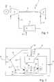
- a turbo group 1comprises a turbine 2, which is designed in particular as a gas turbine, and a compressor 3, which is connected to the turbine 2 via a drive shaft 4.
- the turbo group 1is used in a power plant, in which case the turbine 2 additionally drives a generator 5 via the shaft 4.
- the turbo group 1furthermore comprises a combustion system designated as combustion chamber 6, which has at least one combustion chamber 7 and at least one premix burner 8 arranged upstream of this combustion chamber 7.
- the combustion chamber 6is connected on the input side to the high-pressure side of the compressor 3 and on the output side to the high-pressure side of the turbine 2. Accordingly, the combustion chamber 6 is supplied via an oxidizer 9 from the compressor 3 with oxidizer, in particular air.
- the fuel supplytakes place via a corresponding fuel line 10.
- the hot combustion gasesare supplied to the turbine 2 via a hot gas line 11.
- the combustion chamber 6is used for combustion of a fuel-oxidizer mixture in the combustion chamber 7; the combustion chamber 6 thus forms a device according to the invention. Therefore, this device will be referred to as 6 below.
- Fig. 2is a detailed view of the combustion chamber 6 and the device 6 reproduced. Accordingly, by suitable flow guidance, a total oxidizer stream 12 coming from the compressor 3 is introduced at 13 into a main oxidant stream 14 and a minor oxidizer stream 15. At 16, the sub-oxidant stream 15 is split into a pilot oxidizer stream 17 and a heat exchanger-oxidizer stream 18. Similarly, here too, a total fuel stream 19 at 20 becomes a major fuel Stream 21 and a pilot fuel stream 22 split.
- the splitting of the oxidizer streamscan take place, for example, in a plenum of the combustion chamber 6, so that the splitting stations 13 and 16 coincide.
- the fuel flowmay be a suitable valve or the like. Arranged. It is also possible to provide the pilot fuel stream 22 with its own pump and, in particular, to supply the combustion chamber 6 independently of the main fuel stream 21.
- the main oxidant stream 14 and the main fuel stream 21are supplied to the premix burner 8, whereby a main fuel-oxidizer mixture 23 is formed in the premix burner 8.
- This main fuel-oxidizer mixture 23is then introduced into the combustion chamber 7, where it burns in a complete oxidation.
- the supply of fuel and oxidizertakes place in the premix burner 8 so that a lean main mixture 23 results.
- the device 6 or the combustion chamber 6is also equipped with a catalyst 24, the catalyst material is selected so that it causes partial oxidation of a supplied fuel-oxidizer mixture in certain boundary conditions, such that hydrogen is formed during this partial oxidation.
- the catalyst 24is supplied with a mixture of the pilot oxidant stream 17 and the pilot fuel stream 22.
- the admixing of the pilot fuel stream 22 to the pilot oxidizer stream 17takes place in such a way that a rich pilot fuel-oxidizer mixture 17, 22 is formed.
- the mixture formationcan take place - as here - in an inlet region of the catalyst 24; likewise, the pilot fuel-oxidizer mixture 17, 22 may already be formed upstream of the catalytic converter 24.
- the synthesis gas forming in the catalyst 24 by partial oxidationis hereinafter referred to as partially oxidized pilot fuel-oxidizer mixture, which is introduced into the combustion chamber 7, for example, according to the arrow 25.
- pilot fuel-oxidizer mixturewhich is introduced into the combustion chamber 7, for example, according to the arrow 25.
- further reaction products in the case of a natural gas / air mixtureare essentially carbon monoxide and residual air or residual ester gas.
- the partially oxidized pilot fuel-oxidizer mixture 25is then introduced according to the invention together with the heat exchanger-oxidizer stream 18 into the combustion chamber 7. As a result, at the respective discharge point a very stable pilot flame or pilot combustion can be generated.
- the heat exchanger oxidizer stream 18 and the volumetric flow of the partially oxidized pilot mixture 25are suitably coordinated so that, when mixed, a lean or at least slightly lean mixture is formed.
- the partially oxidized pilot mixture 25 and the heat exchanger oxidizer stream 18are introduced or injected into one or more zones 26, of which Fig. 2 a symbolically bounded by a dotted line. These zones 26 are chosen to be particularly suitable for stabilizing the main combustion of the main fuel-oxidizer mixture 23 formed in the premix burner 8. Such zones 26 are located mainly in the combustion chamber 7.
- At least one such zone 26is in the premix burner 8, so that additionally or alternatively, the partially oxidized pilot mixture 25 together with the heat exchanger-oxidizer stream 18 at a corresponding point in the premix burner 8 are introduced, which, for example, in the embodiments of 3 and 4 is realized.
- suitable zones 26may be, for example: a central recirculation zone in the combustion chamber 7, an external recirculation or dead water zone and a remote from the combustion chamber 7 portion of the Vorrmischbrenners 8.
- the catalyst 24has a catalytically active path 27 and a catalytically inactive path 28, which is coupled to the catalytically active path 27 to transmit heat. While the pilot fuel-oxidizer mixture 17, 22 is introduced into the catalytically active path 27, the catalytically inactive path 28 is traversed by the heat exchanger-oxidizer stream 18. As a result, the heat exchanger-oxidizer stream 18th be used on the one hand for preheating the pilot mixture 17, 22, whose temperature has been lowered by the admixing of the relatively cold pilot fuel stream 22. By preheating the ignition of the catalyst reaction is advantageously shifted toward the inlet end of the catalyst 24.
- the flow through the catalytically inactive path 28 with the heat exchanger-oxidizer stream 18causes a cooling of the catalyst 24, so that the catalyst 24 can be operated in a predetermined and for the desired catalytic reaction particularly suitable temperature window.
- a Butleroxidation of the pilot mixture 17, 22 and the formation of a homogeneous gas reaction in the pilot mixture 17, 22are avoided within the catalyst 24.
- the means used for the supply of the heat exchanger oxidizer stream 18thereby form an oxidizer feed device, in which case the catalytically inactive path 28 of the catalyst 24 forms a component of this oxidizer feed device.
- the catalyst 24may be integrated into the premix burner 8.
- the catalyst 24may be installed in a lance 29, which is centrally located on a head 30 of the benner 8 remote from the combustion chamber 7 and protrudes here in the direction of the combustion chamber 7 into the premix burner 8.
- the reactive, partially oxidized pilot mixture 25is in this case together with the heat exchanger-oxidizer stream 18 injected at the head 30 in the premix burner 8.
- the catalyst 24itself is centrally located in the head 30 of the premix burner 8.
- the catalyst 24may have a plurality of channels 31 and 32 which can be flowed through in parallel, of which one are catalytically active channels 31, while the other are catalytically inactive channels 32.
- the catalytically active channels 31form the catalytically active path 27 of the catalyst 24, while the catalytically inactive channels 32 form the catalytically inactive path 28 of the catalyst 24.
- the catalyst 4In front of the inlet openings of the individual channels 31, 32, the catalyst 4 here has a distribution chamber 33, which is the distribution point 16 in Fig. 2 equivalent.
- the supplied minor oxidant stream 15is distributed to the catalytically active channels 31 (pilot oxidant stream 17) and the catalytically inactive channels 32 (heat exchanger oxidizer stream 18).
- the admixing of the pilot fuel stream 22takes place within the catalytically active channels 31, expediently before a catalytic coating of the catalytically active channels 31.
- the catalytically active channels 31 and the catalytically inactive channels 32are alternately arranged one another.
- the catalytically active channels 31are heat-transmitting coupled to the catalytically inactive channels 32, which can be realized in particular by common boundary walls.
- the individual channels 31, 32 of the catalytic converter 24can be catalytically active or catalytically inactive, line by line, and alternately arranged one row at a time. Accordingly, change in Fig. 5 Lines 34, which consist of juxtaposed catalytically active channels 31, with lines 35, which consist of juxtaposed catalytically inactive channels 32. This results in an alternating layering of the lines 34, 35 transversely to the main flow direction of the catalyst 24.
- Um to separate the introduction of the heat exchanger oxidizer stream 18 into the catalytically inactive channels 32 from the supply of the pilot mixture 17, 22 from pilot fuel stream 22 and pilot oxidant stream 17 into the catalytically active channels 31is the Catalyst 24 upstream of a distributor head 36.
- This distributor head 36has an output 38 connected to an input 37 of the catalytic converter 24.
- the distributor head 36has an in Fig. 5
- the first input 39is connected to a pilot-fuel-oxidizer-mixture line, not shown, which feeds the pilot mixture 17, 22 to the first input 39.
- a heat exchanger-oxidizer line(not shown) which forms part of the abovementioned oxidizer feed device is connected to the second input 40, via which the heat exchanger-oxidizer flow 18 is supplied to the second input 40.
- the distributor head 36is made up of a plurality of shafts 41 and 42 which are adjacent to the main throughflow direction of the catalytic converter 24. All shafts 41, 42 are open to the output 38 of the distributor head 36. The first wells 41 associated with the first input 39 are also open to the first input 39 while being closed to the second input 40. In a corresponding manner, the second slots 40 associated with the second input 40 are open towards the second input 40 and closed towards the first input 39. In this case, the dimensioning of the shafts 41, 42 is matched to the dimensioning of the channels 31, 32 of the catalytic converter 40 so that each shaft outlet covers a row 34, 35.
- the distributor head 36basically has the same structure as in the embodiment according to FIG Fig. 5 ,
- the catalyst 24, the catalytically active channels 31 and the catalytic inactive channels 32 in Fig. 6not more line like in Fig. 5 but arranged in a checkerboard pattern.
- this checkerboard arrangementis rotated relative to a rectangular cross-section of the catalyst 24 by 45 ° about the main flow direction of the catalyst 24, so that quasi a diagonal checkered arrangement of the channels 31, 32 results.
- a perforated plate 43having a plurality of through holes 44 arranged in a predetermined hole pattern 45.
- This hole pattern 45is expediently chosen such that each channel 31, 32 only communicates with one of the shafts 41, 42 via a single through hole 44.
- the holes 44are open on the one hand only to a single well 41, 42 and on the other hand only to a single channel 31, 32 or to a single channel group of catalytically active channels 31 or catalytically inactive channels 32.
- the pilot mixture 17, 22 flowing into the first shafts 41passes exclusively into catalytically active channels 31, while, on the other hand, the heat exchanger oxidizer stream 18 flows exclusively into catalytically inactive channels 32 via the second shafts 42.
- Fig. 7ais a section through the cross section of the catalyst 24 according to Fig. 6 played. Accordingly, the catalytically active channels 31 and the catalytically inactive channels 32 are arranged so that they alternate in a checkerboard pattern.
- Registered linesrepresent the orientations or longitudinal center planes of the respective channels 31, 32 associated shafts 41 and 42 at the exit thereof.
- Fig. 7bgives a line by line alternating arrangement of the catalytically active channels 31 and the catalytically inactive channels 32 according to the in Fig. 5 illustrated embodiment of the catalyst 24 again and otherwise corresponds to the representation according to Fig. 7a ,
- Fig. 7canother advantageous arrangement for the catalytically active channels 31 and the catalytically inactive channels 32 is shown.
- the number of catalytically inactive channels 32 and their share of the total cross-sectional area of the catalyst 24is greater than in the catalytically active channels 31.
- the supply of the heat exchanger-oxidizer stream 18 and the pilot mixture 17, 22then takes place via a corresponding Arrangement of the first shafts 41 and second shafts 42 in the distributor head 36th
- the catalytically active channels 31 and the catalytically inactive channels 32are again arranged like a box, the catalytically active channels 31 being grouped together in groups of four. Accordingly, a significantly larger number of catalytically active channels 31, while the proportion of the total area of the catalyst 24 through which can flow in the catalytically active channels 31 is about the same size as in the catalytically inactive channels 32.
- a catalyst arrangement on the WO 03/033985 A1directed.
- From the WO 03/033985 A1go to a method and a device for supplying and discharging two gases to or from a Multi-channel monolith structure.
- a first and a second gascan be supplied to one another separated from the first and second channels of the monolith structure.
- the channelsare arranged so that each first channel having at least one second channel has a common partition wall through which mass and / or heat exchange between the channels is possible.
Landscapes
- Engineering & Computer Science (AREA)
- Chemical & Material Sciences (AREA)
- Chemical Kinetics & Catalysis (AREA)
- Combustion & Propulsion (AREA)
- Mechanical Engineering (AREA)
- General Engineering & Computer Science (AREA)
Description
Translated fromGermanDie vorliegende Erfindung betrifft ein Verfahren sowie eine Vorrichtung zum Verbrennen eines Brennstoff-Oxidator-Gemischs in einem Brennraum einer Turbogruppe, insbesondere einer Kraftwerksanlage.The present invention relates to a method and a device for burning a fuel-oxidizer mixture in a combustion chamber of a turbo group, in particular a power plant.
Aus der
Aus der
Moderne Vormischbrenner arbeiten mit einem mageren Brennstoff-Oxidator-Gemisch und müssen in der Nähe der Zündgrenze ihres Magergemischs betrieben werden, um die Entstehung von NOX gering zu halten, und um somit die immer schärfer werdenden Emissionsvorschriften erfüllen zu können. Diese Brenner sind folglich sehr anfällig für Instabilitäten des Verbrennungsvorgangs und sind außerdem großen Druckschwankungen ausgesetzt, was sich nachteilig auf die Standzeiten des Brenners, einer nachgeschalteten Brennkammer und einer Gasturbine bzw. deren Schaufeln auswirkt. Es besteht daher das Bedürfnis, bei einem Magermix-Vormischbrenner die Verbrennung zu stabilisieren.Modern premix burners operate with a lean fuel-oxidizer mixture and must be operated near the ignition limit of their lean mixture in order to minimize the formation of NOX , and thus meet the increasingly stringent emissions regulations. Consequently, these burners are very susceptible to instabilities of the combustion process and are also exposed to large pressure fluctuations, which adversely affects the service life of the burner, a downstream combustion chamber and a gas turbine or their blades. Therefore, there is a need to stabilize combustion in a lean burn premix burner.
Hier setzt die Erfindung an. Die vorliegende Erfindung, wie sie in den Ansprüchen gekennzeichnet ist, beschäftigt sich mit dem Problem, für die Verbrennung eines mageren Brennstoff-Oxidator-Gemischs in einem Brennraum einer Turbogruppe Möglichkeiten zur Stabilisierung aufzuzeigen.This is where the invention starts. The present invention, as characterized in the claims, deals with the problem of demonstrating possibilities for stabilization for the combustion of a lean fuel-oxidizer mixture in a combustion chamber of a turbo group.
Erfindungsgemäß wird dieses Problem durch die Gegenstände der unabhängigen Ansprüche gelöst. Vorteilhafte Ausführungsformen sind Gegenstand der abhängigen Ansprüche.According to the invention, this problem is solved by the subject matters of the independent claims. Advantageous embodiments are the subject of the dependent claims.
Die Erfindung beruht auf dem allgemeinen Gedanken, ein fettes Pilot-Brennstoff-Oxidator-Gemisch in einem Katalysator nur teilweise zu oxidieren, derart, dass sich hochreaktiver Wasserstoff bildet, wobei das teiloxidierte, wasserstoffhaltige Gemisch zusammen mit einem zusätzlichen Oxidator-Strom in wenigstens eine Zone eingeleitet wird, die für eine Stabilisierung der Verbrennung des Haupt-Brennstoff-Oxidator-Gemischs geeignet ist. Bei dieser Vorgehensweise wird der für die Volloxidation des teiloxidierten Pilot-Gemischs benötigte Oxidator mit in die für die Verbrennungsstabilisierung geeigneten Zonen eingeleitet bzw. eingedüst, wodurch sich die Stabilität der so erzeugten Pilotflammen erhöht. Gleichzeitig ziehen die Pilotflammen bei Ihrer Verbrennung keinen oder zumindest deutlich weniger Oxidator aus dem Hauptgemisch ab, wodurch auch die Hauptgemischreaktion stabiler ablaufen kann.The invention is based on the general idea of only partially oxidizing a rich pilot fuel-oxidizer mixture in a catalyst such that highly reactive hydrogen forms, the partially oxidized hydrogen-containing mixture, together with an additional oxidant stream, into at least one zone which is suitable for stabilizing the combustion of the main fuel-oxidizer mixture. In this procedure, the required for Volloxidation the partially oxidized pilot mixture oxidizer is introduced or injected into the suitable zones for combustion stabilization, whereby the stability of the pilot flames thus generated increases. At the same time, the pilot flames do not draw any or at least significantly less oxidant from the main mixture when they are burned, which also makes the main mixture reaction more stable.
Besonders günstig für die Stabilisierung der Verbrennung des Haupt-Gemischs hat sich gezeigt, wenn das wasserstoffhaltige, teiloxidierte Pilot-Gemisch und der zusätzliche Oxidator-Strom so dimensioniert werden, dass sich ein mageres Gemisch bildet. Insbesondere kann ein leicht mageres Gemisch angestrebt sein, das nur einen relativ geringen Oxidator-Überschuß besitzt. Der Einfluss auf die Emissionswerte der Haupt-Verbrennung ist dann besonders gering.Particularly favorable for the stabilization of the combustion of the main mixture has been found when the hydrogen-containing, partially oxidized pilot mixture and the additional oxidant stream are dimensioned so that forms a lean mixture. In particular, a slightly lean mixture may be desirable, which has only a relatively small excess of oxidizer. The influence on the emission values of the main combustion is then particularly low.
Gemäß einer besonders vorteilhaften Ausführungsform kann der zusätzlich zugeführte Oxidator-Strom, der im folgenden auch als Wärmeübertrager-Oxidatorstrom bezeichnet wird, zum Vorwärmen des Pilot-Brennstoff-Oxidator-Gemischs und/oder zum Kühlen das Katalysators verwendet werden. Der in einer Turbogruppe verwendete Oxidator stammt in der Regel von der Druckseite eines Verdichters, so dass der Oxidator, üblicherweise Luft, bereits eine relativ hohe Temperatur besitzt. Durch die Eindüsung des Brennstoffs in einen Teilstrom des vom Verdichter stammenden Oxidators wird ein Pilot-Brennstoff-Oxidator-Gemisch gebildet, dessen Temperatur unterhalb der des verdichteten Oxidators liegt, da der Brennstoff, üblicherweise Erdgas, bei der Eindüsung eine relativ niedrige Temperatur aufweist. Dementsprechend kann ein anderer Teilstrom des vom Verdichter stammenden Oxidators zum Vorwärmen des Pilot-Brennstoff-Oxidator-Gemischs genutzt werden, indem eine geeignete Wärmekopplung durchgeführt wird. Hierdurch wird die Zündgrenze der katalytischen Reaktion bereits bei einer relativ kurzen Einlaufstrecke in den Katalysator erreicht, wodurch sich gleichzeitig eine erhöhte Konversionsrate im Katalysator erzielen lässt. Durch die katalytische Reaktion erhöht sich nun die Temperatur des Katalysators. Damit im Katalysator vorwiegend die gewünschte Teiloxidation abläuft, darf die Temperatur im Katalysator nicht zu stark ansteigen, da sonst eine Volloxidation stattfinden und/oder eine homogene Gasreaktion entstehen kann. Der Wärmeübertrager-Oxidator-Strom eignet sich, insbesondere nach seiner Wärmeabgabe an das Pilot-Brennstoff-Oxidator-Gemisch, in besondere Weise zur Kühlung des Katalysators. Hierdurch kann die gewünschte Teiloxidationsreaktion im Katalysator stabilisiert werden.According to a particularly advantageous embodiment, the additionally supplied oxidizer stream, which is also referred to below as the heat exchanger oxidizer stream, can be used for preheating the pilot-fuel-oxidizer mixture and / or for cooling the catalyst. The oxidizer used in a turbo group usually comes from the pressure side of a compressor, so that the oxidizer, usually air, already has a relatively high temperature. By injecting the fuel into a partial stream of the compressor-originating oxidizer, a pilot-fuel-oxidizer mixture is formed whose temperature is below that of the densified oxidizer since the fuel, usually natural gas, has a relatively low temperature during injection. Accordingly, another partial flow of the compressor-derived oxidizer may be used to preheat the pilot fuel-oxidizer mixture be used by a suitable heat coupling is performed. As a result, the ignition limit of the catalytic reaction is achieved even at a relatively short inlet path into the catalyst, which can be achieved at the same time an increased conversion rate in the catalyst. The catalytic reaction now increases the temperature of the catalyst. In order for the desired partial oxidation to take place predominantly in the catalyst, the temperature in the catalyst should not increase too much, since otherwise a full oxidation takes place and / or a homogeneous gas reaction can occur. The heat exchanger oxidizer stream is suitable, in particular for its heat release to the pilot fuel-oxidizer mixture, in a special way for cooling the catalyst. As a result, the desired partial oxidation reaction can be stabilized in the catalyst.
Entsprechend einer bevorzugten Ausführungsform kann der Katalysator mehrere parallel durchströmbare Kanäle aufweisen, von denen die einen katalytisch aktiv und die anderen katalytisch inaktiv sind. Die katalytisch aktiven Kanäle bilden dabei einen katalytisch aktiven Pfad durch den Katalysator, der so gestaltet ist, dass er bei seiner Durchströmung mit dem fetten Pilot-Brennstoff-Oxidator-Gemisch die gewünschte Teiloxidation unter der Ausbildung von Wasserstoff ermöglicht. Die katalytisch inaktiven Kanäle bilden einen katalytisch inaktiven Pfad durch den Katalysator, der im Betrieb vom Wärmeübertrager-Oxidator-Strom durchströmt ist. Durch eine einheitliche Bauweise der Kanäle, also durch die Unterbringung der Kanäle in einer gemeinsamen Struktur des Katalysators, sind die Kanäle wärmeübertragend miteinander gekoppelt. Diese Bauweise ermöglicht somit zum einen ein Vorwärmen des in den Katalysator eingeleiteten Pilot-Brennstoff-Oxidator-Gemischs und zum anderen ein Kühlen des Katalysators. Durch eine gezielte Abstimmung der katalytisch aktiven Kanäle und der katalytisch inaktiven Kanäle, insbesondere im Hinblick auf deren Anzahl, Anordnung und Dimensionierung, kann gezielt ein auf einen Nennbetriebszustand der Vorrichtung, insbesondere der Turbogruppe, ausgelegtes Wärmemanagement für den Katalysator erreicht werden. Dies ermöglicht eine hohe Standzeit für den Katalysator sowie reproduzierbare Verbrennungsreaktionen im Katalysator und somit in den Stabilisierungszonen.According to a preferred embodiment, the catalyst may have a plurality of channels through which it is possible to pass in parallel, one of which is catalytically active and the other catalytically inactive. The catalytically active channels thereby form a catalytically active path through the catalyst, which is designed so that it allows the desired partial oxidation with the formation of hydrogen as it flows through the rich pilot fuel-oxidizer mixture. The catalytically inactive channels form a catalytically inactive path through the catalyst, which is flowed through in operation by the heat exchanger-oxidizer stream. By a uniform construction of the channels, so by the placement of the channels in a common structure of the catalyst, the channels are heat-transmitting coupled together. This construction thus makes it possible, on the one hand, to preheat the pilot-fuel-oxidizer mixture introduced into the catalytic converter and, on the other hand, to cool the catalytic converter. By a targeted coordination of the catalytically active channels and the catalytically inactive channels, in particular with regard to their number, arrangement and dimensioning, a targeted to a nominal operating state of the device, in particular the turbo group, thermal management for the catalyst can be achieved. This allows a long service life for the catalyst and reproducible combustion reactions in the catalyst and thus in the stabilization zones.
Weitere wichtige Merkmale und Vorteile der vorliegenden Erfindung ergeben sich aus den Unteransprüchen, aus den Zeichnungen und aus der zugehörigen Figurenbeschreibung anhand der Zeichnungen.Other important features and advantages of the present invention will become apparent from the dependent claims, from the drawings and from the associated figure description with reference to the drawings.
Bevorzugte Ausführungsbeispiele der Erfindung sind in den Zeichnungen dargestellt und werden in der nachfolgenden Beschreibung näher erläutert, wobei sich gleiche Bezugszeichen auf gleiche oder ähnliche oder funktional gleiche Bauteile beziehen. Es zeigen, jeweils schematisch,
- Fig. 1
- eine schaltplanartige Prinzipdarstellung einer Turbogruppe, die mit einer erfindungsgemäßen Vorrichtung ausgestattet ist,
- Fig. 2
- eine schaltplanartige Prinzipdarstellung einer erfindungsgemäßen Vorrichtung,
- Fig. 3
- eine Prinzipdarstellung im Längsschnitt durch einen Vormischbrenner,
- Fig. 4
- eine Ansicht wie in
Fig. 3 , jedoch bei einer anderen Ausführungsform, - Fig. 5
- eine auseinander gezogene, perspektivische Darstellung eines Katalysators und eines Verteilerkopfs,
- Fig. 6
- eine Darstellung wie in
Fig. 5 , jedoch zusätzlich mit einer Lochplatte, - Fig. 7a bis 7d
- stark vereinfachte Ausschnitte aus einem Querschnitt eines Katalysators bei verschiedenen Ausführungsformen.
- Fig. 1
- a circuit diagram-like schematic representation of a turbo group, which is equipped with a device according to the invention,
- Fig. 2
- a circuit diagram-like schematic diagram of a device according to the invention,
- Fig. 3
- a schematic representation in longitudinal section through a premix burner,
- Fig. 4
- a view like in
Fig. 3 but in another embodiment, - Fig. 5
- an exploded, perspective view of a catalyst and a distributor head,
- Fig. 6
- a representation like in
Fig. 5 , but additionally with a perforated plate, - Fig. 7a to 7d
- highly simplified sections of a cross-section of a catalyst in various embodiments.
Entsprechend
Die Turbogruppe 1 umfaßt außerdem ein als Brennkammer 6 bezeichnetes Verbrennungssystem, das wenigstens einen Brennraum 7 sowie wenigstens einen, diesem Brennraum 7 vorgeschalteten Vormischbrenner 8 aufweist. Die Brennkammer 6 ist eingangsseitig an die Hochdruckseite des Verdichters 3 und ausgangsseitig an die Hochdruckseite der Turbine 2 angeschlossen. Dementsprechend wird die Brennkammer 6 über eine Oxidatorleitung 9 vom Verdichter 3 mit Oxidator, insbesondere Luft, versorgt.The
Die Brennstoffversorgung erfolgt über eine entsprechende Brennstoffleitung 10. Die heißen Verbrennungsgase werden über eine Heißgasleitung 11 der Turbine 2 zugeführt. Die Brennkammer 6 dient zur Verbrennung eines Brennstoff-Oxidator-Gemischs im Brennraum 7; die Brennkammer 6 bildet somit eine Vorrichtung nach der Erfindung. Diese Vorrichtung wird im folgenden daher auch mit 6 bezeichnet.The fuel supply takes place via a corresponding
In
Wie aus dem Schaubild gemäß
Die Vorrichtung 6 bzw. die Brennkammer 6 ist außerdem mit einem Katalysator 24 ausgestattet, dessen Katalysatormaterial so ausgewählt ist, dass es bei bestimmten Randbedingungen eine Teiloxidation eines zugeführten Brennstoff-Oxidator-Gemischs bewirkt, derart, dass bei dieser Teiloxidation Wasserstoff entsteht. Dem Katalysator 24 wird ein Gemisch aus dem Pilot-Oxidator-Strom 17 und dem Pilot-Brennstoff-Strom 22 zugeführt. Die Zumischung des Pilot-Brennstoff-Stroms 22 zum Pilot-Oxidator-Strom 17 erfolgt dabei so, dass sich ein fettes Pilot-Brennstoff-Oxidator-Gemisch 17, 22 bildet. Die Gemischbildung kann dabei - wie hier - in einem Einlaufbereich des Katalysators 24 erfolgen; ebenso kann das Pilot-Brennstoff-Oxidator-Gemisch 17, 22 bereits stromauf des Katalysators 24 gebildet werden. Das sich im Katalysator 24 durch Teiloxidation ausbildende Synthesegas wird im folgenden als teiloxidiertes Pilot-Brennstoff-Oxidator-Gemisch bezeichnet, das entsprechend dem Pfeil 25 beispielsweise in den Brennraum 7 eingeleitet wird. Weitere Reaktionsprodukte bei einem Erdgas-Luft-Gemisch sind neben Wasserstoff im wesentlichen Kohlenmonoxid und Restluft bzw. Resterdgas.The
Das teiloxidierte Pilot-Brennstoff-Oxidator-Gemisch 25 wird dann erfindungsgemäß gemeinsam mit dem Wärmeübertrager-Oxidator-Strom 18 in den Brennraum 7 eingeleitet. Hierdurch kann an der jeweiligen Einleitstelle eine sehr stabile Pilotflamme oder Pilotverbrennung erzeugt werden. Der Wärmeübertrager-Oxidator-Strom 18 und der Volumenstrom des teiloxidierten Pilotgemischs 25 sind zweckmäßig so aufeinander abgestimmt, dass sich bei ihrer Durchmischung ein mageres oder zumindest leicht mageres Gemisch ausbildet.The partially oxidized pilot fuel-
Um mit Hilfe der stabilen Pilotflammen die Hauptverbrennung im Brennraum 7 stabilisieren zu können, werden das teiloxidierte Pilot-Gemisch 25 und der Wärmeübertrager-Oxidator-Strom 18 in eine oder mehrere Zonen 26 eingeleitet bzw. eingedüst, von denen in
Bei der hier gezeigten speziellen Ausführungsform besitzt der Katalysator 24 einen katalytisch aktiven Pfad 27 sowie einen katalytisch inaktiven Pfad 28, der mit dem katalytisch aktiven Pfad 27 wärmeübertragend gekoppelt ist. Während das Pilot-Brennstoff-Oxidator-Gemisch 17, 22 in den katalytisch aktiven Pfad 27 eingeleitet wird, ist der katalytisch inaktive Pfad 28 vom Wärmeübertrager-Oxidator-Strom 18 durchströmt. Hierdurch kann der Wärmeübertrager-Oxidator-Strom 18 einerseits zum Vorwärmen des Pilot-Gemischs 17, 22 genutzt werden, dessen Temperatur durch die Zumischung des relativ kalten Pilot-Brennstoff-Stroms 22 abgesenkt worden ist. Durch die Vorwärmung wird die Zündung der Katalysatorreaktion vorteilhaft in Richtung Einlaufende des Katalysators 24 verschoben. Andererseits bewirkt die Durchströmung des katalytisch inaktiven Pfads 28 mit dem Wärmeübertrager-Oxidator-Strom 18 eine Kühlung des Katalysators 24, so dass der Katalysator 24 in einem vorbestimmten und für die gewünschte katalytische Reaktion besonders geeigneten Temperaturfenster betrieben werden kann. Durch die Kühlung des Katalysators 24 werden innerhalb des Katalysators 24 insbesondere eine Volloxidation des Pilot-Gemischs 17, 22 sowie die Entstehung einer homogenen Gasreaktion im Pilot-Gemisch 17, 22 vermieden.In the specific embodiment shown here, the
Es ist klar, dass im Katalysator 24 bzw. in dessen katalytisch aktiven Pfad 27 neben der Teiloxidation auch eine Volloxidation des Pilot-Gemischs 17, 22 stattfinden kann. Darüber hinaus kann es bei relativ niedrigen Temperaturen und bei der Verwendung von Erdgas als Brennstoff dazu kommen, dass im Katalysator 24 eine endotherme Dampf-Reformierung stattfindet, wodurch die Produktion von Wasserstoff und beispielsweise Kohlenmonoxid verbessert werden kann. Des weiteren ist es möglich, dem Katalysator 24 bzw. dem Pilot-Gemisch 17, 22 Dampf zuzuführen.It is clear that in the
Die für die Zuführung des Wärmeübertrager-Oxidator-Stroms 18 verwendeten Mittel bilden dabei eine Oxidator-Zuführeinrichtung, wobei hier der katalytisch inaktive Pfad 28 des Katalysators 24 einen Bestandteil dieser Oxidator-Zuführeinrichtung bildet.The means used for the supply of the heat
Entsprechend den
Im folgenden wird eine spezielle Ausführungsform des Katalysators 24 anhand
Entsprechend
Der Verteilerkopf 36 ist aus mehreren, quer zur Hauptdurchströmungsrichtung des Katalysators 24 benachbarten Schächten 41 und 42 aufgebaut. Alle Schächte 41, 42 sind zum Ausgang 38 des Verteilerkopfs 36 hin offen. Die dem ersten Eingang 39 zugeordneten ersten Schächte 41 sind außerdem zum ersten Eingang 39 hin offen, während sie zum zweiten Eingang 40 hin geschlossen sind. In entsprechender Weise sind die dem zweiten Eingang 40 zugeordneten zweiten Schächte 42 zum zweiten Eingang 40 hin offen und zum ersten Eingang 39 hin geschlossen. Dabei ist die Dimensionierung der Schächte 41, 42 auf die Dimensionierung der Kanäle 31, 32 des Katalysators 40 so abgestimmt, dass jeder Schachtausgang eine Zeile 34, 35 abdeckt. Da die ersten Schächte 41 und die zweiten Schächte 42 einander abwechselnd nebeneinander angeordnet sind, ergibt sich dadurch die gewünschte Aufteilung der dem Verteilerkopf 36 zugeführten Strömungen, nämlich Pilot-Gemisch 17, 22 einerseits und Wärmeübertrager-Oxidator-Strom 18 andererseits, auf die einzelnen Zeilen 34, 35 des Katalysators 24.The
Bei der Ausführungsform gemäß
Durch die speziellen Maßnahmen der Ausführungsformen gemäß den
In
In
Bei der Ausführungsform gemäß
Im Übrigen wird für weitere Varianten und Ausführungsformen einer derartigen Katalysator-Anordnung auf die
- 11
- TurbogruppeTurbo group
- 22
- Turbineturbine
- 33
- Verdichtercompressor
- 44
- Wellewave
- 55
- Generatorgenerator
- 66
- Vorrichtung/BrennkammerDevice / combustion chamber
- 77
- Brennraumcombustion chamber
- 88th
- Vormischbrennerpremix
- 99
- OxidatorleitungOxidatorleitung
- 1010
- Brennstoffleitungfuel line
- 1111
- HeißgasleitungHot gas line
- 1212
- Gesamt-Oxidator-StromTotal oxidant stream
- 1313
- AufteilstelleAufteilstelle
- 1414
- Haupt-Oxidator-StromMain oxidant stream
- 1515
- Neben-Oxidator-StromBesides oxidizer stream
- 1616
- AufteilstelleAufteilstelle
- 1717
- Pilot-Oxidator-StromPilot oxidizer flow
- 1818
- Wärmeübertrager-Oxidator-StromHeat exchanger-oxidant power
- 1919
- Gesamt-Brennstoff-StromTotal fuel flow
- 2020
- AufteilstelleAufteilstelle
- 2121
- Haupt-Brennstoff-StromMain fuel stream
- 2222
- Pilot-Brennstoff-StromPilot fuel flow
- 2323
- Haupt-Brennstoff-Oxidator-GemischMain fuel-oxidizer mixture
- 2424
- Katalysatorcatalyst
- 2525
- oxidiertes Pilot-Brennstoff-Oxidator-Gemischoxidized pilot fuel-oxidizer mixture
- 2626
- ZoneZone
- 2727
- katalytisch aktiver Pfadcatalytically active path
- 2828
- katalytisch inaktiver Pfadcatalytically inactive path
- 2929
- Lanzelance
- 3030
- Kopf von 8Head of 8
- 3131
- katalytisch aktiver Kanalcatalytically active channel
- 3232
- katalytisch inaktiver Kanalcatalytically inactive channel
- 3333
- Verteilerkammerdistribution chamber
- 3434
- Zeile mit katalytisch aktiven KanälenLine with catalytically active channels
- 3535
- Zeile mit katalytisch inaktiven KanälenLine with catalytically inactive channels
- 3636
- Verteilerkopfdistribution head
- 3737
- Eingang von 24Entrance from 24
- 3838
- Ausgang von 36Output of 36
- 3939
- erster Eingang von 36first entrance of 36
- 4040
- zweiter Eingang von 36second entrance of 36
- 4141
- erster Schachtfirst shaft
- 4242
- zweiter Schachtsecond shaft
- 4343
- Lochplatteperforated plate
- 4444
- DurchgangslochThrough Hole
- 4545
- Lochmusterhole pattern
Claims (15)
- Method for combusting a fuel-oxidising agent mixture in a combustion chamber (7) of a group of turbogenerators (1), in particular of a power plant,- wherein a total oxidising agent flow (12) is divided into a main oxidising agent flow (14) and a secondary oxidising agent flow (15),- wherein said main oxidising agent flow (14) is leanly mixed with a main fuel flow (21) in a premixing burner (8) and this main fuel-oxidising agent mixture (23) is fully oxidised in the combustion chamber (7),- wherein the secondary oxidising agent flow (15) is divided into a pilot oxidising agent flow (17) and a heat transmitter-oxidising agent flow (18),- wherein the pilot oxidising agent flow (17) is richly mixed with a pilot fuel flow (22) and the mixture (17, 22) is partially oxidised in a catalyst (24), producing hydrogen,- wherein the partially oxidised pilot fuel-oxidising agent mixture (25) and the heat transmitter-oxidising agent flow (18) are together, after the catalyst (24), conducted into at least one zone (26) which is suitable for stabilising the combustion of the main fuel-oxidising agent mixture (23).
- Method according to claim 1,characterised in that the heat transmitter-oxidising agent flow (18) and the partially oxidised pilot fuel-oxidising agent mixture (25) are leanly or slightly leanly mixed after the catalyst (24).
- Method according to claim 1 or 2,characterised in that the heat transmitter-oxidising agent flow (18) is used to preheat the pilot fuel-oxidising agent mixture (25) and/or to cool the catalyst (24).
- Method according to any of claims 1 to 3,characterised in that- the catalyst (124) has several through-flow parallel channels (31, 32), of which some (31) are catalytically active and others (32) are catalytically inactive,- the pilot fuel-oxidising agent mixture (17, 22) is conducted through the catalytically active channels (31),- the heat transmitter-oxidising agent flow (18) is conducted through the catalytically inactive channels (32).
- Method according to claim 4,characterised in that the catalytically active channels (31) and the catalytically inactive channels (32) are coupled together heat-transmissively.
- Device (6) with a combustion chamber (7) for combusting a fuel-oxidising agent mixture in a group of turbogenerators (1), in particular of a power plant,- with a premix burner (8) in which, in operation of the device (6), a main oxidising agent flow is leanly mixed with a main fuel flow (21) and this main fuel-oxidising agent mixture (23) is fully oxidised,- with at least one catalyst (24) which is configured, when a rich pilot fuel-oxidising agent mixture (17, 22) passes through it in operation of the device (6), to perform a partial oxidisation, forming hydrogen,- with an oxidising agent supply device (28, 32) which, in operation of the device (6), mixes a heat transmitter-oxidising agent flow (18) into the partially oxidised pilot fuel-oxidising agent mixture (25) downstream of the catalyst (24),- wherein the catalyst (24) and the oxidising agent supply device (28, 32) are configured such that, in operation of the device (6), the partially oxidised pilot fuel-oxidising agent mixture (25) and the heat transmitter-oxidising agent flow (18) are conducted jointly into at least one zone (26) which is suitable for stabilising the combustion of the main fuel-oxidising agent mixture (23),characterised in that- a distributor head (36) is mounted upstream of the catalyst (24) and is connected via a first input (39) to a pilot fuel-oxidising agent mixture line, via a second input (40) to a heat transmitter-oxidising agent line, and via an output (38) to the catalyst (24), and- the distributor head (36) comprises a plurality of shafts (41, 42) which are adjacent transversely to the flow direction, all of which are open at the output (38) and optionally at the first input (39) or at the second input (40).
- Device according to claim 6,characterised in that- the catalyst (24) has a through-flow catalytically active path (27) and a through-flow catalytically inactive path (28) parallel thereto,- the catalytically active path (27) is configured, when a rich pilot fuel-oxidising agent mixture (17, 22) flows through it, to perform a partial oxidisation, forming hydrogen,- the catalytically inactive path (28) is coupled heat-transmissively to the catalytically active path (27) and forms a constituent part of the oxidising agent supply device and, in operation of the device (6), the heat transmitter-oxidising agent flow (18) passes through said path.
- Device according to claim 7,characterised in that:- the catalyst (24) has several through-flow parallel channels (31, 32), of which some (31) are catalytically active and others (32) are catalytically inactive,- the catalytically active path (27) of the catalyst (24) is formed by its catalytically active channels (31),- the catalytically inactive path (28) of the catalyst (24) is formed by its catalytically inactive channels (32).
- Device according to claim 8,characterised in that a pilot fuel line is connected to the catalytically active channels (31) such that, in operation of the device (6), it conducts the pilot fuel flow (22) separately into the individual catalytically active channels (31).
- Device according to claim 7 or 8,characterised in that- a pilot oxidising agent line is connected to the catalytically active path (27),- a pilot fuel line is connected to the pilot oxidising agent line upstream of the catalyst (24).
- Device according to any of claims 6 to 10,characterised in that the catalyst (24) is arranged concentrically in a head (30) of the premix burner (8).
- Device according to any of claims 6 to 10,characterised in that the catalyst (24) is arranged in a lance (29) which is arranged concentrically in a head (30) of the premix burner (8) and protrudes into the premix burner (8).
- Device according to claims 6 and 8,characterised in that- the catalytically active channels (31) and the catalytically inactive channels (32) are distributed so that first rows (34) of catalytically active channels (31) arranged next to each other and second rows (35) of catalytically inactive channels (32) arranged next to each other are arranged alternately, in particular as rows,- the first shafts (41) open to the first input (39) adjoin the first rows (34), and the second shafts (42) open to the second input (40) adjoin the second rows (35).
- Device according to claims 6 or 13,characterised in that a perforated plate (43) is arranged between the distributor head (36) and the catalyst (24), the perforation pattern (45) of which is selected such that each channel (31, 32) communicates with one of the shafts (41, 42) through a single passage hole (44).
- Device according to claim 14,characterised in that- the catalytically active channels (31) and the catalytically inactive channels (32) are arranged alternately in a chequerboard pattern,- the perforation pattern (45) of the perforated plate (43) and the arrangement of the channels (31, 32) are matched to each other such that the catalytically active channels (31) communicate via the assigned passage holes (44) with the first shafts (41) which lead to the first input (39) of the distributor head (36), while the catalytically inactive channels (32) communicate via the assigned passage holes (44) with the second shafts (42) which lead to the second input (40) of the distributor head (36).
Applications Claiming Priority (3)
| Application Number | Priority Date | Filing Date | Title |
|---|---|---|---|
| US40697902P | 2002-08-30 | 2002-08-30 | |
| US406979P | 2002-08-30 | ||
| PCT/CH2003/000542WO2004020905A1 (en) | 2002-08-30 | 2003-08-12 | Method and device for combusting a fuel-oxidising agent mixture |
Publications (2)
| Publication Number | Publication Date |
|---|---|
| EP1532400A1 EP1532400A1 (en) | 2005-05-25 |
| EP1532400B1true EP1532400B1 (en) | 2017-07-26 |
Family
ID=31978397
Family Applications (1)
| Application Number | Title | Priority Date | Filing Date |
|---|---|---|---|
| EP03790608.8AExpired - LifetimeEP1532400B1 (en) | 2002-08-30 | 2003-08-12 | Method and device for combusting a fuel-oxidising agent mixture |
Country Status (5)
| Country | Link |
|---|---|
| US (1) | US7421844B2 (en) |
| EP (1) | EP1532400B1 (en) |
| CN (1) | CN100489397C (en) |
| AU (1) | AU2003249830A1 (en) |
| WO (1) | WO2004020905A1 (en) |
Families Citing this family (49)
| Publication number | Priority date | Publication date | Assignee | Title |
|---|---|---|---|---|
| EP1532400B1 (en) | 2002-08-30 | 2017-07-26 | Ansaldo Energia Switzerland AG | Method and device for combusting a fuel-oxidising agent mixture |
| WO2004020902A1 (en) | 2002-08-30 | 2004-03-11 | Alstom Technology Ltd | Method and device for mixing fluid flows |
| DE102004041794A1 (en)* | 2004-03-30 | 2005-10-20 | Alstom Technology Ltd Baden | Device for flame stabilizing in burner has catalyser assembly upstream of flame and through which flows air/pilot fuel mixture separate from air/fuel mixture, whereby catalyser assembly has at least two stages located in series |
| EP1730441B1 (en)* | 2004-03-30 | 2008-03-19 | Alstom Technology Ltd | Device and method for stabilizing the flame in a burner |
| EP1738109A1 (en)* | 2004-03-31 | 2007-01-03 | Alstom Technology Ltd | Catalytic reactor and method for burning fuel-air mixtures by means of a catalytic reactor |
| EP1614963A1 (en)* | 2004-07-09 | 2006-01-11 | Siemens Aktiengesellschaft | Premix Combustion System and Method |
| WO2006100176A1 (en)* | 2005-03-23 | 2006-09-28 | Alstom Technology Ltd | Method and device for combusting hydrogen in a premix burner |
| DE102005061486B4 (en) | 2005-12-22 | 2018-07-12 | Ansaldo Energia Switzerland AG | Method for operating a combustion chamber of a gas turbine |
| US7841180B2 (en)* | 2006-12-19 | 2010-11-30 | General Electric Company | Method and apparatus for controlling combustor operability |
| US8671658B2 (en) | 2007-10-23 | 2014-03-18 | Ener-Core Power, Inc. | Oxidizing fuel |
| US8393160B2 (en) | 2007-10-23 | 2013-03-12 | Flex Power Generation, Inc. | Managing leaks in a gas turbine system |
| US7928596B2 (en) | 2008-10-06 | 2011-04-19 | General Electric Company | Systems and methods for the utilization of energy generated by a powered vehicle |
| US8701413B2 (en)* | 2008-12-08 | 2014-04-22 | Ener-Core Power, Inc. | Oxidizing fuel in multiple operating modes |
| US20100175386A1 (en)* | 2009-01-09 | 2010-07-15 | General Electric Company | Premixed partial oxidation syngas generation and gas turbine system |
| US8621869B2 (en) | 2009-05-01 | 2014-01-07 | Ener-Core Power, Inc. | Heating a reaction chamber |
| US20100275611A1 (en)* | 2009-05-01 | 2010-11-04 | Edan Prabhu | Distributing Fuel Flow in a Reaction Chamber |
| EP2299178B1 (en) | 2009-09-17 | 2015-11-04 | Alstom Technology Ltd | A method and gas turbine combustion system for safely mixing H2-rich fuels with air |
| IT1397215B1 (en)* | 2009-12-29 | 2013-01-04 | Ansaldo Energia Spa | BURNER ASSEMBLY FOR A GAS TURBINE SYSTEM AND A GAS TURBINE SYSTEM INCLUDING THE BURNER ASSEMBLY |
| WO2011116010A1 (en) | 2010-03-15 | 2011-09-22 | Flexenergy, Inc. | Processing fuel and water |
| NL2006526C2 (en)* | 2011-04-01 | 2012-10-02 | Heatmatrix Group B V | Device and method for mixing two fluids. |
| WO2012142188A2 (en) | 2011-04-11 | 2012-10-18 | Milwaukee Electric Tool Corporation | Hydraulic hand-held knockout punch driver |
| US9057028B2 (en) | 2011-05-25 | 2015-06-16 | Ener-Core Power, Inc. | Gasifier power plant and management of wastes |
| US9279364B2 (en) | 2011-11-04 | 2016-03-08 | Ener-Core Power, Inc. | Multi-combustor turbine |
| US9273606B2 (en) | 2011-11-04 | 2016-03-01 | Ener-Core Power, Inc. | Controls for multi-combustor turbine |
| RU2014130185A (en)* | 2011-12-27 | 2016-02-20 | Кавасаки Дзюкогё Кабусики Кайся | CATALYTIC COMBUSTION CAMERA OF A GAS TURBINE ENGINE |
| US9273608B2 (en) | 2012-03-09 | 2016-03-01 | Ener-Core Power, Inc. | Gradual oxidation and autoignition temperature controls |
| US9726374B2 (en) | 2012-03-09 | 2017-08-08 | Ener-Core Power, Inc. | Gradual oxidation with flue gas |
| US9534780B2 (en) | 2012-03-09 | 2017-01-03 | Ener-Core Power, Inc. | Hybrid gradual oxidation |
| US9347664B2 (en) | 2012-03-09 | 2016-05-24 | Ener-Core Power, Inc. | Gradual oxidation with heat control |
| US9381484B2 (en) | 2012-03-09 | 2016-07-05 | Ener-Core Power, Inc. | Gradual oxidation with adiabatic temperature above flameout temperature |
| US9353946B2 (en) | 2012-03-09 | 2016-05-31 | Ener-Core Power, Inc. | Gradual oxidation with heat transfer |
| US9328660B2 (en) | 2012-03-09 | 2016-05-03 | Ener-Core Power, Inc. | Gradual oxidation and multiple flow paths |
| US8980193B2 (en) | 2012-03-09 | 2015-03-17 | Ener-Core Power, Inc. | Gradual oxidation and multiple flow paths |
| US9328916B2 (en) | 2012-03-09 | 2016-05-03 | Ener-Core Power, Inc. | Gradual oxidation with heat control |
| US8671917B2 (en) | 2012-03-09 | 2014-03-18 | Ener-Core Power, Inc. | Gradual oxidation with reciprocating engine |
| US8807989B2 (en) | 2012-03-09 | 2014-08-19 | Ener-Core Power, Inc. | Staged gradual oxidation |
| US9267432B2 (en) | 2012-03-09 | 2016-02-23 | Ener-Core Power, Inc. | Staged gradual oxidation |
| US9371993B2 (en) | 2012-03-09 | 2016-06-21 | Ener-Core Power, Inc. | Gradual oxidation below flameout temperature |
| US9206980B2 (en) | 2012-03-09 | 2015-12-08 | Ener-Core Power, Inc. | Gradual oxidation and autoignition temperature controls |
| US8926917B2 (en) | 2012-03-09 | 2015-01-06 | Ener-Core Power, Inc. | Gradual oxidation with adiabatic temperature above flameout temperature |
| US9234660B2 (en) | 2012-03-09 | 2016-01-12 | Ener-Core Power, Inc. | Gradual oxidation with heat transfer |
| US9017618B2 (en) | 2012-03-09 | 2015-04-28 | Ener-Core Power, Inc. | Gradual oxidation with heat exchange media |
| US8980192B2 (en) | 2012-03-09 | 2015-03-17 | Ener-Core Power, Inc. | Gradual oxidation below flameout temperature |
| US9567903B2 (en) | 2012-03-09 | 2017-02-14 | Ener-Core Power, Inc. | Gradual oxidation with heat transfer |
| US9359948B2 (en) | 2012-03-09 | 2016-06-07 | Ener-Core Power, Inc. | Gradual oxidation with heat control |
| US8844473B2 (en) | 2012-03-09 | 2014-09-30 | Ener-Core Power, Inc. | Gradual oxidation with reciprocating engine |
| US9359947B2 (en) | 2012-03-09 | 2016-06-07 | Ener-Core Power, Inc. | Gradual oxidation with heat control |
| EP3324113A1 (en)* | 2016-11-17 | 2018-05-23 | Saacke GmbH | Method and device for operating a gas combustor |
| US12037952B2 (en)* | 2022-01-04 | 2024-07-16 | General Electric Company | Systems and methods for providing output products to a combustion chamber of a gas turbine engine |
Family Cites Families (15)
| Publication number | Priority date | Publication date | Assignee | Title |
|---|---|---|---|---|
| FR1069211A (en)* | 1952-12-26 | 1954-07-06 | Gaz Et Chaleur | Hot air generator by catalytic combustion |
| FR2436958A2 (en) | 1978-09-22 | 1980-04-18 | Ceraver | PROCESS FOR THE MANUFACTURE OF AN INDIRECT HEAT EXCHANGE ELEMENT IN CERAMIC MATERIAL, AND ELEMENT OBTAINED BY THIS PROCESS |
| US4298059A (en) | 1978-09-23 | 1981-11-03 | Rosenthal Technik Ag | Heat exchanger and process for its manufacture |
| US5634784A (en)* | 1991-01-09 | 1997-06-03 | Precision Combustion, Inc. | Catalytic method |
| US5235804A (en) | 1991-05-15 | 1993-08-17 | United Technologies Corporation | Method and system for combusting hydrocarbon fuels with low pollutant emissions by controllably extracting heat from the catalytic oxidation stage |
| US5165224A (en)* | 1991-05-15 | 1992-11-24 | United Technologies Corporation | Method and system for lean premixed/prevaporized combustion |
| US5207053A (en)* | 1991-05-15 | 1993-05-04 | United Technologies Corporation | Method and system for staged rich/lean combustion |
| GB9212794D0 (en) | 1992-06-16 | 1992-07-29 | Ici Plc | Catalytic combustion |
| US5512250A (en)* | 1994-03-02 | 1996-04-30 | Catalytica, Inc. | Catalyst structure employing integral heat exchange |
| DE4439619A1 (en) | 1994-11-05 | 1996-05-09 | Abb Research Ltd | Method and device for operating a premix burner |
| DE19654022A1 (en) | 1996-12-21 | 1998-06-25 | Abb Research Ltd | Process for operating a gas turbine group |
| US20020015931A1 (en)* | 1999-03-18 | 2002-02-07 | Lance Smith | Conduit positioner |
| US6358040B1 (en)* | 2000-03-17 | 2002-03-19 | Precision Combustion, Inc. | Method and apparatus for a fuel-rich catalytic reactor |
| NO321805B1 (en) | 2001-10-19 | 2006-07-03 | Norsk Hydro As | Method and apparatus for passing two gases in and out of the channels of a multi-channel monolithic unit. |
| EP1532400B1 (en) | 2002-08-30 | 2017-07-26 | Ansaldo Energia Switzerland AG | Method and device for combusting a fuel-oxidising agent mixture |
- 2003
- 2003-08-12EPEP03790608.8Apatent/EP1532400B1/ennot_activeExpired - Lifetime
- 2003-08-12WOPCT/CH2003/000542patent/WO2004020905A1/ennot_activeApplication Discontinuation
- 2003-08-12CNCNB038247747Apatent/CN100489397C/ennot_activeExpired - Fee Related
- 2003-08-12AUAU2003249830Apatent/AU2003249830A1/ennot_activeAbandoned
- 2003-08-12USUS11/066,926patent/US7421844B2/ennot_activeExpired - Fee Related
Non-Patent Citations (1)
| Title |
|---|
| None* |
Also Published As
| Publication number | Publication date |
|---|---|
| CN100489397C (en) | 2009-05-20 |
| EP1532400A1 (en) | 2005-05-25 |
| US20060080968A1 (en) | 2006-04-20 |
| US7421844B2 (en) | 2008-09-09 |
| WO2004020905A1 (en) | 2004-03-11 |
| CN1703601A (en) | 2005-11-30 |
| AU2003249830A1 (en) | 2004-03-19 |
Similar Documents
| Publication | Publication Date | Title |
|---|---|---|
| EP1532400B1 (en) | Method and device for combusting a fuel-oxidising agent mixture | |
| EP1730441B1 (en) | Device and method for stabilizing the flame in a burner | |
| DE3854666T2 (en) | GAS TURBINE BURNER. | |
| DE3889301T2 (en) | Combustion chamber to reduce pollutant emissions from gas turbines. | |
| DE69625744T2 (en) | Lean premix burner with low NOx emissions for industrial gas turbines | |
| DE69729505T2 (en) | How a gas turbine combustor works | |
| WO2004094909A1 (en) | Method and device for operating a burner of a heat engine, especially a gas turbine plant | |
| EP2116766A1 (en) | Fuel lance | |
| DE2940431A1 (en) | COMBUSTION CHAMBER WITH STAGE FUEL INJECTION AND METHOD FOR OPERATING A HIGH TEMPERATURE COMBUSTION CHAMBER | |
| EP1861657A1 (en) | Method and device for combusting hydrogen in a premix burner | |
| WO2003091626A1 (en) | Combustion chamber with flameless oxidation | |
| WO2005095856A1 (en) | Catalytic reactor and method for burning fuel-air mixtures by means of a catalytic reactor | |
| EP1301697B1 (en) | Gas turbine and method for operating a gas turbine | |
| DE102020212410A1 (en) | Gas turbine combustion apparatus | |
| EP0889289B1 (en) | Gas turbine system and method of operation thereof | |
| DE102020212361B4 (en) | GAS TURBINE COMBUSTION DEVICE | |
| CH702737A2 (en) | Combustion chamber with two combustion chambers. | |
| DE3102165A1 (en) | Burner/boiler combination with an improved burner and combustion process | |
| EP1072758A2 (en) | Method for cooling gas turbine blades | |
| EP1963748B1 (en) | Combustion chamber with burner and associated operating method | |
| EP1446610A1 (en) | Method of combustion, in particular methods for the production of electrical current and/or heat | |
| EP3246557A1 (en) | Rocket propulsion system and method for operating same | |
| EP0210205B1 (en) | Device for combustion of liquid and gas fuels producing nitrogen oxide-free exhaust gases | |
| DE102013112162A1 (en) | Mikromischerdüse | |
| EP3246558B1 (en) | Method for operating a rocket propulsion system and rocket propulsion system |
Legal Events
| Date | Code | Title | Description |
|---|---|---|---|
| PUAI | Public reference made under article 153(3) epc to a published international application that has entered the european phase | Free format text:ORIGINAL CODE: 0009012 | |
| 17P | Request for examination filed | Effective date:20050221 | |
| AK | Designated contracting states | Kind code of ref document:A1 Designated state(s):AT BE BG CH CY CZ DE DK EE ES FI FR GB GR HU IE IT LI LU MC NL PT RO SE SI SK TR | |
| AX | Request for extension of the european patent | Extension state:AL LT LV MK | |
| DAX | Request for extension of the european patent (deleted) | ||
| RBV | Designated contracting states (corrected) | Designated state(s):DE GB | |
| RIN1 | Information on inventor provided before grant (corrected) | Inventor name:WINKLER, DIETER Inventor name:GRIFFIN, TIMOTHY | |
| 17Q | First examination report despatched | Effective date:20070906 | |
| RAP1 | Party data changed (applicant data changed or rights of an application transferred) | Owner name:GENERAL ELECTRIC TECHNOLOGY GMBH | |
| GRAP | Despatch of communication of intention to grant a patent | Free format text:ORIGINAL CODE: EPIDOSNIGR1 | |
| INTG | Intention to grant announced | Effective date:20170209 | |
| RAP1 | Party data changed (applicant data changed or rights of an application transferred) | Owner name:ANSALDO ENERGIA SWITZERLAND AG | |
| GRAS | Grant fee paid | Free format text:ORIGINAL CODE: EPIDOSNIGR3 | |
| GRAA | (expected) grant | Free format text:ORIGINAL CODE: 0009210 | |
| AK | Designated contracting states | Kind code of ref document:B1 Designated state(s):DE GB | |
| REG | Reference to a national code | Ref country code:GB Ref legal event code:FG4D Free format text:NOT ENGLISH | |
| REG | Reference to a national code | Ref country code:DE Ref legal event code:R096 Ref document number:50315681 Country of ref document:DE | |
| PGFP | Annual fee paid to national office [announced via postgrant information from national office to epo] | Ref country code:GB Payment date:20170822 Year of fee payment:15 Ref country code:DE Payment date:20170822 Year of fee payment:15 | |
| REG | Reference to a national code | Ref country code:DE Ref legal event code:R097 Ref document number:50315681 Country of ref document:DE | |
| PLBE | No opposition filed within time limit | Free format text:ORIGINAL CODE: 0009261 | |
| STAA | Information on the status of an ep patent application or granted ep patent | Free format text:STATUS: NO OPPOSITION FILED WITHIN TIME LIMIT | |
| 26N | No opposition filed | Effective date:20180430 | |
| REG | Reference to a national code | Ref country code:DE Ref legal event code:R119 Ref document number:50315681 Country of ref document:DE | |
| GBPC | Gb: european patent ceased through non-payment of renewal fee | Effective date:20180812 | |
| PG25 | Lapsed in a contracting state [announced via postgrant information from national office to epo] | Ref country code:DE Free format text:LAPSE BECAUSE OF NON-PAYMENT OF DUE FEES Effective date:20190301 | |
| PG25 | Lapsed in a contracting state [announced via postgrant information from national office to epo] | Ref country code:GB Free format text:LAPSE BECAUSE OF NON-PAYMENT OF DUE FEES Effective date:20180812 |