EP1525901A1 - Particle therapy system - Google Patents
Particle therapy systemDownload PDFInfo
- Publication number
- EP1525901A1 EP1525901A1EP04025097AEP04025097AEP1525901A1EP 1525901 A1EP1525901 A1EP 1525901A1EP 04025097 AEP04025097 AEP 04025097AEP 04025097 AEP04025097 AEP 04025097AEP 1525901 A1EP1525901 A1EP 1525901A1
- Authority
- EP
- European Patent Office
- Prior art keywords
- charged particle
- particle beam
- energy
- collimator
- ion beam
- Prior art date
- Legal status (The legal status is an assumption and is not a legal conclusion. Google has not performed a legal analysis and makes no representation as to the accuracy of the status listed.)
- Granted
Links
- 238000002727particle therapyMethods0.000titleclaimsabstractdescription20
- 239000002245particleSubstances0.000claimsabstractdescription105
- 238000011144upstream manufacturingMethods0.000claimsabstractdescription13
- 238000000605extractionMethods0.000claimsdescription9
- 230000002238attenuated effectEffects0.000claimsdescription6
- 230000001678irradiating effectEffects0.000claimsdescription6
- 238000010884ion-beam techniqueMethods0.000abstractdescription119
- 238000012545processingMethods0.000abstractdescription21
- RYGMFSIKBFXOCR-UHFFFAOYSA-NCopperChemical compound[Cu]RYGMFSIKBFXOCR-UHFFFAOYSA-N0.000description39
- 229910052802copperInorganic materials0.000description39
- 239000010949copperSubstances0.000description39
- 206010028980NeoplasmDiseases0.000description14
- 201000011510cancerDiseases0.000description13
- 101000642630Homo sapiens Sine oculis-binding protein homologProteins0.000description9
- 102100036670Sine oculis-binding protein homologHuman genes0.000description9
- 239000006096absorbing agentSubstances0.000description8
- 229920001721polyimidePolymers0.000description7
- 150000002500ionsChemical class0.000description6
- 238000000034methodMethods0.000description6
- 238000009826distributionMethods0.000description4
- 238000005259measurementMethods0.000description4
- XLYOFNOQVPJJNP-UHFFFAOYSA-NwaterSubstancesOXLYOFNOQVPJJNP-UHFFFAOYSA-N0.000description4
- 238000000790scattering methodMethods0.000description3
- 238000003892spreadingMethods0.000description3
- 230000007480spreadingEffects0.000description3
- 238000005452bendingMethods0.000description2
- 229910052799carbonInorganic materials0.000description2
- -1carbon ionsChemical class0.000description2
- 238000001514detection methodMethods0.000description2
- 210000001508eyeAnatomy0.000description2
- 230000006870functionEffects0.000description2
- 230000008569processEffects0.000description2
- 238000012360testing methodMethods0.000description2
- OKTJSMMVPCPJKN-UHFFFAOYSA-NCarbonChemical compound[C]OKTJSMMVPCPJKN-UHFFFAOYSA-N0.000description1
- 239000004642PolyimideSubstances0.000description1
- 230000000903blocking effectEffects0.000description1
- 210000005252bulbus oculiAnatomy0.000description1
- 238000010276constructionMethods0.000description1
- 238000005520cutting processMethods0.000description1
- 230000007423decreaseEffects0.000description1
- 239000001064degraderSubstances0.000description1
- 239000012777electrically insulating materialSubstances0.000description1
- 238000010030laminatingMethods0.000description1
- 239000000463materialSubstances0.000description1
- 229920003223poly(pyromellitimide-1,4-diphenyl ether)Polymers0.000description1
- 238000002360preparation methodMethods0.000description1
- 230000005855radiationEffects0.000description1
- 230000009467reductionEffects0.000description1
- 230000004044responseEffects0.000description1
- 238000012552reviewMethods0.000description1
- 238000002560therapeutic procedureMethods0.000description1
- WFKWXMTUELFFGS-UHFFFAOYSA-NtungstenChemical compound[W]WFKWXMTUELFFGS-UHFFFAOYSA-N0.000description1
- 229910052721tungstenInorganic materials0.000description1
- 239000010937tungstenSubstances0.000description1
Images


Classifications
- A—HUMAN NECESSITIES
- A61—MEDICAL OR VETERINARY SCIENCE; HYGIENE
- A61N—ELECTROTHERAPY; MAGNETOTHERAPY; RADIATION THERAPY; ULTRASOUND THERAPY
- A61N5/00—Radiation therapy
- A61N5/10—X-ray therapy; Gamma-ray therapy; Particle-irradiation therapy
- A61N5/1048—Monitoring, verifying, controlling systems and methods
- G—PHYSICS
- G21—NUCLEAR PHYSICS; NUCLEAR ENGINEERING
- G21K—TECHNIQUES FOR HANDLING PARTICLES OR IONISING RADIATION NOT OTHERWISE PROVIDED FOR; IRRADIATION DEVICES; GAMMA RAY OR X-RAY MICROSCOPES
- G21K5/00—Irradiation devices
- G21K5/04—Irradiation devices with beam-forming means
- A—HUMAN NECESSITIES
- A61—MEDICAL OR VETERINARY SCIENCE; HYGIENE
- A61N—ELECTROTHERAPY; MAGNETOTHERAPY; RADIATION THERAPY; ULTRASOUND THERAPY
- A61N5/00—Radiation therapy
- A61N5/10—X-ray therapy; Gamma-ray therapy; Particle-irradiation therapy
- A61N5/1048—Monitoring, verifying, controlling systems and methods
- A61N2005/1074—Details of the control system, e.g. user interfaces
- A—HUMAN NECESSITIES
- A61—MEDICAL OR VETERINARY SCIENCE; HYGIENE
- A61N—ELECTROTHERAPY; MAGNETOTHERAPY; RADIATION THERAPY; ULTRASOUND THERAPY
- A61N5/00—Radiation therapy
- A61N5/10—X-ray therapy; Gamma-ray therapy; Particle-irradiation therapy
- A61N2005/1085—X-ray therapy; Gamma-ray therapy; Particle-irradiation therapy characterised by the type of particles applied to the patient
- A61N2005/1087—Ions; Protons
- A—HUMAN NECESSITIES
- A61—MEDICAL OR VETERINARY SCIENCE; HYGIENE
- A61N—ELECTROTHERAPY; MAGNETOTHERAPY; RADIATION THERAPY; ULTRASOUND THERAPY
- A61N5/00—Radiation therapy
- A61N5/10—X-ray therapy; Gamma-ray therapy; Particle-irradiation therapy
- A61N2005/1092—Details
- A61N2005/1095—Elements inserted into the radiation path within the system, e.g. filters or wedges
- A—HUMAN NECESSITIES
- A61—MEDICAL OR VETERINARY SCIENCE; HYGIENE
- A61N—ELECTROTHERAPY; MAGNETOTHERAPY; RADIATION THERAPY; ULTRASOUND THERAPY
- A61N5/00—Radiation therapy
- A61N5/10—X-ray therapy; Gamma-ray therapy; Particle-irradiation therapy
- A61N5/1048—Monitoring, verifying, controlling systems and methods
- A61N5/1075—Monitoring, verifying, controlling systems and methods for testing, calibrating, or quality assurance of the radiation treatment apparatus
Definitions
- the present inventionrelates to a particle beam irradiation apparatus for use in medical treatment to accelerate and irradiate a particle beam.
- the present inventionalso relates to a safety device for the particle beam irradiation apparatus.
- an acceleratoraccelerates a charged particle beam, i.e., a particle beam (such as a proton beam or a heavy charged-particle beam (e.g., a carbon ion beam)), and the accelerated charged particle beam is used for treatment of cancers (diseased parts).
- the particle therapy systemincludes an irradiation nozzle for irradiating the charged particle beam to a cancer.
- the particle beamwill be referred to as an "ion beam” hereinafter.
- the irradiation nozzlespreads the ion beam in match with the cancer in a direction perpendicular to the direction of advance of the ion beam. This process is called spread of an irradiation field.
- Non-Patent Reference 1"REVIEW OF SCIENTIFIC INSTRUMENTS", Vol. 64, No. 8 (August 1993), pp. 2076-2086
- a wobbling methodsee Patent Reference 1; JP,A 2000-202047, and Non-Patent Reference 1).
- a scattereris installed in a beam path within the irradiation nozzle to enlarge the ion beam through scattering by the scatterer.
- a pair of scanning magnets provided in the irradiation nozzleare energized to scan the ion beam so as to draw a circle, thereby spreading the ion beam.
- the irradiation nozzlefurther includes a SOPB (spread-out of Bragg peak) device (e.g., a ridge filter or a range modulation wheel) for spreading out an energy distribution to increase the range in the direction of advance of the ion beam, a fine degrader for adjusting the energy of the ion beam to final irradiation energy, a collimator for cutting the ion beam that is not necessary for the irradiation, a dose monitor, and a beam position monitor.
- SOPBread-out of Bragg peak
- the energy (namely, range) of the ion beam irradiated to the cancercan be measured by a water phantom device (see Patent Reference 2; JP,A 11-64530) attached in the irradiation nozzle.
- the energy of the ion beamcan also be measured by laminating metallic plates and detecting, from each of the metallic plates, the amount of charges lost through the metallic plates when the ion beam passes them.
- the water phantom deviceWhen measuring the energy of the ion beam by the water phantom device, the water phantom device has hitherto been arranged in the beam path within the irradiation nozzle before start of the cancer treatment. After end of the energy measurement, the water phantom device is moved away from the beam path so as not to interfere with the ion beam used for the treatment. With the related art thus constructed, the energy of the ion beam cannot be measured during a period in which the treatment is performed under irradiation of the ion beam.
- a charged particle beam irradiation apparatuscomprises a collimator for passing a part of a charged particle beam therethrough, and an energy measuring device including a charged particle beam entrance portion disposed upstream of the collimator to receive at least a part of the remaining charged particle beam, for measuring energy of the charged particle beam having entered the charged particle beam entrance portion.
- the energy of the charged particle beamcan be measured while the charged particle beam having passed a beam passage formed by the collimator is irradiated to an irradiation target (e.g., a patient).
- an irradiation targete.g., a patient
- the charged particle beam entrance portion disposed upstream of the collimatoris mounted to the collimator.
- the charged particle beam entrance portion and the collimatorcan be moved together, and therefore the structure of the charged particle beam irradiation apparatus can be simplified.
- the particle therapy systemfurther comprises a safety device for stopping extraction of the charged particle beam from a charged particle beam generation apparatus when a measured energy value of the charged particle beam measured by the energy measuring device exceeds a setting energy value.
- a safety devicefor stopping extraction of the charged particle beam from a charged particle beam generation apparatus when a measured energy value of the charged particle beam measured by the energy measuring device exceeds a setting energy value.
- the irradiation position of the charged particle beam in a direction of depth from an entrance surface of the irradiation targetis deviated from the predetermined position (i.e., the irradiation position set in a treatment plan).
- the provision of the safety devicecan prevent the charged particle beam from being irradiated to the irradiation position different from the predetermined one.
- an energy attenuating deviceis disposed which is movable in a direction intersecting a beam path along which the charged particle beam passes, and which attenuates the energy of the charged particle beam having entered the charged particle beam entrance portion.
- the energy measuring devicecompensates a measured energy value of the charged particle beam having entered the charged particle beam entrance portion based on a value by which the energy of the charged particle beam has attenuated through the energy attenuating device.
- the energy of the charged particle beam having high energycan be measured with high accuracy by employing the charged particle beam entrance portion that has a relatively small thickness in the direction of advance of the charged particle beam.
- the thickness of the charged particle beam entrance portion in the direction of advance of the charged particle beamis reduced, the length of the charged particle beam irradiation apparatus in the direction of advance of the charged particle beam can be reduced as compared with the case not employing the energy attenuating device.
- the energy of the charged particle beamcan be measured while continuing the irradiation of the charged particle beam.
- a particle therapy system according to one embodiment of the present inventionwill be described below with reference to Figs. 1 and 2.
- a particle therapy system 1 of this embodimentcomprises a charged particle beam generation apparatus 2 and an irradiation nozzle (charged particle beam irradiation apparatus) 18.
- the charged particle beam generation apparatus 2comprises an ion source (not shown), a pre-accelerator 3, and a synchrotron 4.
- Ionse.g., protons or carbon ions
- the pre-acceleratore.g., a linear accelerator
- This embodimentis practiced as a proton beam therapy system using a proton beam as an ion beam.
- the ion beam emitted from the pre-accelerator 3enters the synchrotron 4.
- the ion beamis accelerated in the synchrotron 4 serving as an accelerator in which it is given with energy by radiofrequency (RF) power applied from an RF cavity 5.
- RFradiofrequency
- a switch 15is closed in accordance with an extraction command from an accelerator controller 49.
- RF power from an RF power supply 14is applied to an RF knockout electrode 6 through the switch 15, and an RF wave is applied to the circulating ion beam from the RF knockout electrode 6.
- a switch 63is kept closed.
- the ion beam circulating in the synchrotron 4 within a separatrixis forced to transit to the outside of the separatrix and to exit from the synchrotron 4 through an extraction deflector 13.
- currents supplied to magnets, such as quadrupole magnets 7 and bending magnets 8, disposed in the synchrotron 4are held at respective setting values, and therefore the separatrix is also held substantially constant.
- the extraction of the ion beam from the synchrotron 4is stopped by opening the switch 15 in accordance with an extraction stop command from accelerator controller 49 and ceasing the application of the RF power to the RF knockout electrode 6.
- the ion beam extracted from the synchrotron 4reaches the irradiation nozzle 18, serving as the irradiation apparatus, through a beam transportation line 9.
- An inverted U-shaped section 10 as a part of the beam transportation line 9 and the irradiation nozzle 18are both mounted on a rotating gantry (not shown).
- the inverted U-shaped section 10includes bending magnets 11, 12.
- the ion beamis irradiated from the irradiation nozzle 18 to a cancer (diseased part) 62 (Fig. 1) in the body of a patient 61 lying on a treatment couch (bed) 59.
- a shutter 16 opened and closed by a driving unit 17is disposed in the beam transportation line 9. The shutter 16 is kept open while the ion beam is irradiated to the cancer 62 from the irradiation nozzle 18.
- the irradiation nozzle 18is a wobbling type system.
- the irradiation nozzle 18has a casing 19 mounted to the inverted U-shaped section 10.
- the following unitsare arranged successively from the upstream side in the direction of advance of the ion beam, i.e., scanning magnets 20, 21, a scatterer device 22, a range adjuster 25, a device for spreading out the Bragg peak (referred to as an "SOBP device” hereinafter) 28, a beam energy attenuating device 50, a block collimator 30, a bolus 59, and a patient collimator 60.
- SOBP devicea device for spreading out the Bragg peak
- An energy detector 33(see Fig. 3) is disposed upstream of the block collimator 30 and is mounted to the block collimator 30.
- the scanning magnets 20, 21are mounted to the casing 19 upstream of the scatterer device 22.
- the scatterer device 22includes a scatterer 23 attached to a support member 24 having an opening.
- the support member 24is mounted to the casing 19.
- the range adjuster 25comprises an absorber 26 and a support member 27 for holding the absorber 26 with respect to the casing 19.
- a ridge filter and a rotating range modulation wheelare known as examples of the SOBP device 28. In this embodiment, the ridge filter is used as the SOBP device 28.
- the SOBP device 28is held by a support member 29 which is mounted to the casing 19.
- the block collimator 30comprises a pair of collimator members 31A, 31B.
- the collimator members 31A, 31Bare each made of a radiation shield material, e.g., lead or tungsten, capable of blocking off the ion beam.
- the collimator members 31A, 31Bare movably mounted to a pair of linear guides 37 disposed within the casing 19 in horizontally intersecting relation.
- the pair of linear guides 37are arranged with a space left between them so as not to interfere with the ion beam, and are fixedly mounted to an inner surface of the casing 19.
- a driving unit 38is disposed at an end of one of the linear guides 37, and a driving unit 39 is disposed at an end of the other linear guide 37.
- the driving unit 38is coupled to the collimator member 31A
- the driving unit 39is coupled to the collimator member 31B.
- the collimator members 31A, 31Bare moved in opposite directions (i.e., in directions approaching each other or directions away from each other) along the linear guides 37.
- a space formed between the collimator members 31A, 31Bi.e., a beam passage 35
- the beam passage 35is narrowed. The width of the beam passage 35 is adjusted depending on the size of the cancer 62.
- An energy measuring device 32comprises the energy detector 33 and a signal processing unit 42 (see Fig. 4).
- the energy detector 33is of a structure comprising many thin copper sheets (electrodes) 40 and polyimide films 41 which are alternately arranged in parallel.
- the energy detector 33is constituted by arranging eighty copper sheets 40 each having a thickness of 0.15 mm side by side in the direction of advance of the ion beam.
- Each copper sheet 40serves as an energy sensor.
- the copper sheets 40 and the polyimide films 41 thus arrangedare detachably fixed to the collimator member 31B by attaching a retainer 34 to the collimator member 31B with screws (not shown).
- Polyimideis an electrically insulating material, and each polyimide film 41 serves to prevent electrical connection between adjacent two of the copper sheets 40. Because the copper sheets 40 of the energy detector 33 have the function of attenuating the energy of the ion beam, the thickness of the collimator member 31B is set to be smaller than that of the collimator member 31A. Even if some of the ion beam passes through the energy detector 33, it can be completed blocked off by the collimator member 31B which is disposed downstream of the energy detector 33.
- the signal processing unit 42comprises an analog signal processing unit 43 and a digital signal processing unit 44.
- the copper sheets 40are connected to the analog signal processing unit 43 by respective wires 45.
- the analog signal processing unit 43has individual amplifiers (not shown) in one-to-one relation to the copper sheets 40.
- the wires 45connect the copper sheets 40 to the corresponding amplifiers.
- the amplifiersare each connected to the digital signal processing unit 44.
- This embodimentincludes a control system 60 comprising an irradiation controller 54, a memory 55, and driving controllers 56, 57.
- the control system 60further comprises a driving controller (not shown) for controlling respective movements of the scatterer 23 and the absorber 26 which are described later in more detail.
- the signal processing unit 42(specifically the digital signal processing unit 44) is connected to an interlock device 47 serving as a safety device.
- the interlock device 47is connected to a shutter controller 48 and the switch 63.
- the beam energy attenuating device 50comprises an energy attenuator 51 made of copper and a driving unit 52.
- the energy attenuator 51is movable along a guide member 53 extending in a direction perpendicular to the direction of advance of the ion beam.
- the guide member 53is mounted to the inner surface of the casing 19. The thickness of the energy attenuator 51 is much larger than that of the copper sheet 40.
- the irradiation controller 54Prior to positioning of a patient 61 relative to the irradiation nozzle 18, the irradiation controller 54 receives treatment plan information for the patient 61 (such as an irradiation field size (irradiation field information), a range (range information) and incident energy (beam energy information)) from a treatment planning device 58, and then stores the received data in the memory 55.
- the treatment plan informationrepresents conditions for irradiating the ion beam.
- the irradiation controller 54selects the scatterer 23 and the absorber 26 each having a thickness required to meet the irradiation conditions.
- Respective driving controllersmove the selected scatterer 23 and absorber 26 to a beam path (beam axis m) in the casing 19. The scatterer 23 and the absorber 26 are thus positioned to lie on the beam axis m.
- the irradiation controller 54outputs a first movement command for the collimator members 31A, 31B to the driving controller 57.
- the driving controller 57operates the driving units 38, 39 in accordance with the first movement command such that the collimator members 31A, 31B are moved to respective predetermined positions.
- the beam passage 35 formed between the collimator members 31A, 31Bhas a width corresponding to the irradiation field size set for the patient 61.
- the energy detector 33is also moved together with the collimator member 31B to reach a predetermined position (i.e., a position where the energy detector 33 intersects a part of an ion beam passing area which is located on the left side of a left broken line shown in Fig. 5).
- a predetermined positioni.e., a position where the energy detector 33 intersects a part of an ion beam passing area which is located on the left side of a left broken line shown in Fig. 5.
- the irradiation controller 54outputs a second movement command to the driving controller 56.
- the driving controller 56operates the driving unit 52 in accordance with the second movement command such that the energy attenuator 51 is moved along the guide member 53 to a predetermined position where it intersects a portion of the beam path.
- the energy attenuator 51is moved to a position where it overlies the energy detector 33 in exactly aligned relation without projecting into the beam passage 35.
- the driving unit 52is not operated and the energy attenuator 51 is held in a position where it does not overlap with the energy detector 33.
- the energy attenuator 51must be positioned in exactly aligned relation to the energy detector 33.
- a rotating gantryis rotated to make the beam axis m of the irradiation nozzle 18 oriented at a predetermined angle. With that positioning, the beam axis m of the irradiation nozzle 18 is aligned with the cancer 62 in the body of the patient 61. The preparations for irradiating the ion beam to the patient 61 are thereby completed. Subsequently, as described above, the ion beam having entered the synchrotron 4 from the pre-accelerator 3 is caused to exit from the synchrotron 4 and reach the irradiation nozzle 18. At this time, the shutter 16 is in the open state.
- the ion beamis spread out by the scatterer 23 in the direction perpendicular to the beam axis m, and the range of the ion beam is adjusted by the absorber 26. Further, the ion beam passes through the SOBP device 28 and reaches above the block collimator 30. At this time, the ion beam is spread out as indicated by 36 in Fig. 3. A part of the ion beam passes the beam passage 35. The ion beam having passed the beam passage 35 is irradiated to the cancer 62 after passing through the bolus 59 and the patient collimator 60. In such a way, the treatment of the cancer 62 is performed by the irradiation of the ion beam.
- the energy detector 33detects the energy of the ion beam by receiving the ion beam that is not used for the treatment, namely that is not irradiated to the cancer. That condition will now be described in detail with reference to Fig. 5.
- the ion beam having passed through the SOBP device 28has a distribution of beam intensity indicated by a solid line in a graph of Fig. 5.
- the ion beam locating within an area formed between a pair of broken lines in the distribution graphis irradiated to the cancer 62.
- the ion beam locating within an area on the right side of the right broken line in Fig. 5strikes against the collimator member 31A and is blocked off.
- the ion beam (unnecessary ion beam) locating within an area on the left side of the left broken line in Fig. 5passes through the energy attenuator 51 and then enters the energy detector 33.
- the energy of the ion beamis attenuated by the energy attenuator 51.
- An amount by which the energy of the ion beam is attenuated by the energy attenuator 51is measured in advance and therefore it is a known value.
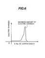
- Each of the copper sheetswhich are included in a zone ranging from the copper sheet 40 which the ion beam first enters to the copper sheet 40 which the ion beam finally reaches, generates electric charges corresponding to an amount of energy loss of the ion beam having entered the relevant copper sheet 40.
- the ion beamis stopped in the copper sheet 40 where the ion beam energy has become 0 (i.e., in one copper sheet which is located at the deepest position among the copper sheets which the ion beam has entered), while releasing a maximum amount of electric charges (see Fig. 6).
- Respective amounts of electric charges generated by the copper sheets 40are amplified by the corresponding amplifiers in the analog signal processing unit 43 through the respective wires 45, and then transmitted to the digital signal processing unit 44.
- the digital signal processing unit 44Based on the input amounts of electric charges, the digital signal processing unit 44 recognizes the address of the copper sheet 40 that has outputted the maximum amount of electric charges.
- the addresses of the copper sheets 40mean the numbers successively assigned to the copper sheets, counting from the surface side of the energy detector 33 closer to the SOBP device 28 in the direction of advance of the ion beam.
- the digital signal processing unit 44stores, in a memory (not shown), the addresses successively assigned as Nos. 1, 2, etc. to the respective copper sheets 40, starting from the surface side of the energy detector 33 closer to the SOBP device 28 in the direction of advance of the ion beam.
- each of the addressesrepresents at what number the relevant copper sheet 40 locates, counting from the surface side of the energy detector 33 closer to the SOBP device 28.
- the digital signal processing unit 44searches for corresponding one of the addresses stored in the memory in accordance with a charge input point from the copper sheet 40 that has outputted the maximum amount of electric charges (i.e., the position connected to the relevant copper sheet 40), thereby recognizing the address of the copper sheet 40 that has outputted the maximum amount of electric charges. Then, the digital signal processing unit 44 determines the energy of the ion beam in accordance with the recognized address of the copper sheet 40.
- the relationship between each copper sheet and the energy of the ion beamis determined in advance based on a test. More specifically, the address of the copper sheet 40 outputting the maximum amount of electric charges is confirmed by causing the ion beams having various levels of energy to enter the energy detector 33 in each of the cases where the ion beam passes through the energy attenuator 51 and where the ion beam does not pass through it.
- the digital signal processing unit 44stores, in the memory, information that is obtained from the test result and represents the correspondent relationship between each energy level and the address of the copper sheet 40 outputting the maximum amount of electric charges which corresponds to each energy level.
- the information representing the correspondent relationshipis prepared separately for each the case where the energy attenuator 51 is positioned in partly intersecting relation to the ion beam passing area and the case where the energy attenuator 51 is not so positioned.
- the digital signal processing unit 44can determine the energy of the ion beam at that time based on the information representing the correspondent relationship between the energy and the address, which is stored in the memory (i.e., direct measurement of the ion beam energy).
- true energy of the ion beamcan be determined by compensating the ion beam energy determined from the address of the copper sheet 40 having outputted the maximum amount of electric charges based on a value by which the ion beam energy has attenuated through the energy attenuator 51 (i.e., compensated measurement of the ion beam energy). Because the polyimide film 41 is very thin (e.g., 75 ⁇ m), there is little probability that an ion beam will stop at the position of polyimide film 41.
- the digital signal processing unit 44outputs the energy value information thus obtained to the interlock device 47 serving as the safety device.
- the interlock device 47receives, from the treatment planning device 53, the beam energy information (setting energy value) for the patient 61 under the treatment by irradiation of the ion beam, and then compares the setting energy value with the energy value (measured energy value) from the digital signal processing unit 44. When the measured energy value exceeds the setting energy value, the interlock device 47 opens the switch 63. As a result, the application of RF power to the RF knockout electrode 6 is stopped, whereby the extraction of the ion beam from the synchrotron 4 is forcibly stopped. Further, when the measured energy value exceeds the setting energy value, the interlock device 47 outputs a shutter closing signal to the shutter controller 48. In response to the shutter closing signal, the shutter controller 48 closes the shutter 16.
- the interlock device 47When the measured energy value is not larger than the setting energy value, the interlock device 47 does not open the switch 63. Accordingly, the extraction of the ion beam from the synchrotron 4 is continued, and the ion beam having exited from the irradiation nozzle 18 is irradiated to the patient 61. The shutter 16 is kept in the open state.
- the ion beam energycan be measured while the ion beam having passed the beam passage 35 is irradiated to the patient 61. Also, when the ion beam energy exceeds the setting energy value during a period in which the ion beam is irradiated for the treatment of the patient 61, the extraction of the ion beam from the synchrotron 4 can be stopped. As a result, the ion beam having energy in excess of the energy setting value can be prevented from being irradiated to the patient 61.
- the energy detector 33since the energy detector 33 is installed on the collimator member 31B, the energy detector 33 and the collimator member 31B can be both moved by one driving unit 39. This eliminates the necessity of installing separate driving units for the energy detector 33 and the collimator member 31B, whereby the construction of the irradiation nozzle can be simplified. Since the beam energy attenuating device 50, specifically the energy attenuator 51, is positioned upstream of the energy detector 33, a detectable energy range of the ion beam can be increased by utilizing the energy attenuator 51. In other words, the energy of the ion beam having a high level of energy can also be detected.
- the energy attenuator 51were not installed, it would be required to noticeably increase not only the number of the copper sheets 40 constituting the energy detector 33, but also the number of Kapton (polyimide) films, thus resulting in a greatly increased thickness of the energy detector 33 in the direction of the beam axis m.
- the provision of the beam energy attenuating device 50can realize a great reduction in thickness of the energy detector 33 in the direction of the beam axis m.
- the ion beam energycan be measured while the ion beam is irradiated to the patient 61.
- the energy detector 33may be separated from the collimator member 31B and disposed upstream of the block collimator 30 in the casing 19. However, this case requires two driving units to be installed to individually move the energy detector 33 and the collimator member 31B.
- the irradiation nozzle 18 used in the above-described embodimentis also applicable to a treatment room not equipped with the rotating gantry.
- an irradiation nozzle for irradiating the ion beam to the eyeis not installed on the rotating gantry and hence it is not rotated.
- Such an irradiation nozzle for treating a cancer produced in an eyeballcan also be constituted by the irradiation nozzle 18 described above.
- the ion beam having exited from the synchrotron 4is similarly introduced to the irradiation nozzle for use in the treatment of the eye.
- the energy measuring device 32 used in the above-described embodimentis also applicable to a particle therapy system employing a cyclotron instead of a synchrotron.
- the interlock device 47opens a power supply switch for an ion source emitting an ion beam to the cyclotron, and also outputs a shutter closing signal to the shutter controller 48. With the opening of the switch, the emission of the ion beam from the ion source is stopped, whereby the irradiation of the ion beam to the patient 61 is also stopped.
- the reason why the power supply switch for the ion source is openedis that the cyclotron is not provided with the RF knockout electrode.
Landscapes
- Health & Medical Sciences (AREA)
- Engineering & Computer Science (AREA)
- Biomedical Technology (AREA)
- Pathology (AREA)
- Nuclear Medicine, Radiotherapy & Molecular Imaging (AREA)
- Radiology & Medical Imaging (AREA)
- Life Sciences & Earth Sciences (AREA)
- Animal Behavior & Ethology (AREA)
- General Health & Medical Sciences (AREA)
- Public Health (AREA)
- Veterinary Medicine (AREA)
- Physics & Mathematics (AREA)
- General Engineering & Computer Science (AREA)
- High Energy & Nuclear Physics (AREA)
- Radiation-Therapy Devices (AREA)
- Particle Accelerators (AREA)
Abstract
Description
Claims (12)
- A particle therapy system comprising a chargedparticle beam generation apparatus and a charged particlebeam irradiation apparatus for irradiating a chargedparticle beam generated by said charged particle beamgeneration apparatus to an irradiation target,
wherein said charged particle beam irradiationapparatus comprises a collimator for passing a part of thecharged particle beam therethrough, and an energy measuringdevice including a charged particle beam entrance portiondisposed upstream of said collimator to receive at least apart of the remaining charged particle beam, for measuringthe energy of the charged particle beam having entered saidcharged particle beam entrance portion. - A particle therapy system according to Claim 1,
wherein said charged particle beam entrance portion ismounted to said collimator. - A particle therapy system according to Claim 2,further comprising a moving device for moving saidcollimator in a direction intersecting a beam path alongwhich the charged particle beam passes.
- A particle therapy system according to one ofClaims 1 to 3, further comprising a safety device forstopping extraction of the charged particle beam from said charged particle beam generation apparatus when a measuredenergy value of the charged particle beam measured by saidenergy measuring device exceeds a setting energy value.
- A particle therapy system according to Claim 1 or 2,further comprising an energy attenuating device disposedupstream of said charged particle beam entrance portion soas to be movable in a direction intersecting a beam pathalong which the charged particle beam passes, forattenuating the energy of the charged particle beam havingentered said charged particle beam entrance portion,
wherein said energy measuring device compensates ameasured energy value of the charged particle beam havingentered said charged particle beam entrance portion based ona value by which the energy of the charged particle beam hasattenuated through said energy attenuating device. - A particle therapy system according to Claim 3,further comprising an energy attenuating device disposedupstream of said charged particle beam entrance portion soas to be movable in a direction intersecting said beam path,for attenuating the energy of the charged particle beamhaving entered said charged particle beam entrance portion,
wherein said energy measuring device compensates ameasured energy value of the charged particle beam havingentered said charged particle beam entrance portion based ona value by which the energy of the charged particle beam hasattenuated through said energy attenuating device. - A particle therapy system according to Claim 3,further comprising a controller for controlling said movingdevice such that said collimator is moved to a positiondetermined depending on an irradiation field size set forsaid irradiation target.
- A charged particle beam irradiation apparatus forirradiating a charged particle beam generated by a chargedparticle beam generation apparatus to an irradiation target,
wherein said charged particle beam irradiationapparatus comprises a collimator for passing a part of thecharged particle beam therethrough, and an energy measuringdevice including a charged particle beam entrance portiondisposed upstream of said collimator to receive at least apart of the remaining charged particle beam, and measuringenergy of the charged particle beam having entered saidcharged particle beam entrance portion. - A charged particle beam irradiation apparatusaccording to Claim 8, wherein said charged particle beamentrance portion is mounted to said collimator.
- A charged particle beam irradiation apparatusaccording to Claim 9, further comprising a moving device formoving said collimator in a direction intersecting a beampath along which the charged particle beam passes.
- A charged particle beam irradiation apparatusaccording to Claim 8, wherein said energy measuring devicemeasurers the energy of the charged particle beam based on aposition at which electric charges generate in maximumamount with incidence of the charged particle beam upon saidcharged particle beam entrance portion.
- A charged particle beam irradiation apparatusaccording to Claim 8, wherein said charged particle beamentrance portion comprises a plurality of metallic sheetsarranged side by side in a direction of advance of thecharged particle beam and generating electric charges withincidence of the charged particle beam, and said energymeasuring device measurers the energy of the chargedparticle beam based on a position at which the metallicsheet having generated a maximum amount of electric chargesis arranged.
Applications Claiming Priority (2)
| Application Number | Priority Date | Filing Date | Title |
|---|---|---|---|
| JP2003363992 | 2003-10-24 | ||
| JP2003363992AJP4114590B2 (en) | 2003-10-24 | 2003-10-24 | Particle beam therapy system |
Publications (2)
| Publication Number | Publication Date |
|---|---|
| EP1525901A1true EP1525901A1 (en) | 2005-04-27 |
| EP1525901B1 EP1525901B1 (en) | 2009-08-12 |
Family
ID=34386535
Family Applications (1)
| Application Number | Title | Priority Date | Filing Date |
|---|---|---|---|
| EP04025097AExpired - LifetimeEP1525901B1 (en) | 2003-10-24 | 2004-10-21 | Particle therapy system |
Country Status (4)
| Country | Link |
|---|---|
| US (2) | US7247869B2 (en) |
| EP (1) | EP1525901B1 (en) |
| JP (1) | JP4114590B2 (en) |
| DE (1) | DE602004022496D1 (en) |
Cited By (3)
| Publication number | Priority date | Publication date | Assignee | Title |
|---|---|---|---|---|
| EP1732369A2 (en) | 2005-06-07 | 2006-12-13 | Hitachi, Ltd. | Charged particle beam extraction system and method |
| EP2196241A1 (en)* | 2008-12-12 | 2010-06-16 | Koninklijke Philips Electronics N.V. | Therapeutic apparatus |
| EP1530410B1 (en)* | 2003-11-07 | 2017-02-08 | Hitachi, Ltd. | Particle therapy system |
Families Citing this family (153)
| Publication number | Priority date | Publication date | Assignee | Title |
|---|---|---|---|---|
| CA2465511C (en) | 2001-10-30 | 2007-12-18 | Loma Linda University Medical Center | Method and device for delivering radiotherapy |
| US7102144B2 (en)* | 2003-05-13 | 2006-09-05 | Hitachi, Ltd. | Particle beam irradiation apparatus, treatment planning unit, and particle beam irradiation method |
| US7317192B2 (en)* | 2003-06-02 | 2008-01-08 | Fox Chase Cancer Center | High energy polyenergetic ion selection systems, ion beam therapy systems, and ion beam treatment centers |
| CA2533680C (en) | 2003-08-12 | 2014-09-16 | Loma Linda University Medical Center | Modular patient support system |
| JP3685194B2 (en)* | 2003-09-10 | 2005-08-17 | 株式会社日立製作所 | Particle beam therapy device, range modulation rotation device, and method of attaching range modulation rotation device |
| EP1584353A1 (en)* | 2004-04-05 | 2005-10-12 | Paul Scherrer Institut | A system for delivery of proton therapy |
| US7073508B2 (en) | 2004-06-25 | 2006-07-11 | Loma Linda University Medical Center | Method and device for registration and immobilization |
| EP1790203B1 (en) | 2004-07-21 | 2015-12-30 | Mevion Medical Systems, Inc. | A programmable radio frequency waveform generator for a synchrocyclotron |
| DE102005035141A1 (en)* | 2005-07-22 | 2007-02-01 | GSI Gesellschaft für Schwerionenforschung mbH | irradiation device |
| EP1752992A1 (en)* | 2005-08-12 | 2007-02-14 | Siemens Aktiengesellschaft | Apparatus for the adaption of a particle beam parameter of a particle beam in a particle beam accelerator and particle beam accelerator with such an apparatus |
| JP5245193B2 (en)* | 2005-09-07 | 2013-07-24 | 株式会社日立製作所 | Charged particle beam irradiation system and charged particle beam extraction method |
| EP1785161A1 (en)* | 2005-11-11 | 2007-05-16 | Siemens Aktiengesellschaft | Treatment room of a particle therapy system, treatment plan, method of creating a treatment plan, and method of irradiation treatment |
| DE102005053971B4 (en)* | 2005-11-11 | 2009-08-27 | Siemens Ag | Particle therapy system with a fluoroscopy system for continuous acquisition of fluoroscopic image data |
| EP2389977A3 (en) | 2005-11-18 | 2012-01-25 | Still River Systems, Inc. | Charged particle radiation therapy |
| JP5448831B2 (en) | 2006-11-21 | 2014-03-19 | ローマ リンダ ユニヴァーシティ メディカル センター | Apparatus and method for securing a patient for breast radiation therapy |
| US8003964B2 (en) | 2007-10-11 | 2011-08-23 | Still River Systems Incorporated | Applying a particle beam to a patient |
| US8581523B2 (en) | 2007-11-30 | 2013-11-12 | Mevion Medical Systems, Inc. | Interrupted particle source |
| US8933650B2 (en) | 2007-11-30 | 2015-01-13 | Mevion Medical Systems, Inc. | Matching a resonant frequency of a resonant cavity to a frequency of an input voltage |
| US8569717B2 (en) | 2008-05-22 | 2013-10-29 | Vladimir Balakin | Intensity modulated three-dimensional radiation scanning method and apparatus |
| US9737272B2 (en)* | 2008-05-22 | 2017-08-22 | W. Davis Lee | Charged particle cancer therapy beam state determination apparatus and method of use thereof |
| US8129699B2 (en) | 2008-05-22 | 2012-03-06 | Vladimir Balakin | Multi-field charged particle cancer therapy method and apparatus coordinated with patient respiration |
| US8399866B2 (en) | 2008-05-22 | 2013-03-19 | Vladimir Balakin | Charged particle extraction apparatus and method of use thereof |
| US9682254B2 (en) | 2008-05-22 | 2017-06-20 | Vladimir Balakin | Cancer surface searing apparatus and method of use thereof |
| US8045679B2 (en)* | 2008-05-22 | 2011-10-25 | Vladimir Balakin | Charged particle cancer therapy X-ray method and apparatus |
| US8373143B2 (en) | 2008-05-22 | 2013-02-12 | Vladimir Balakin | Patient immobilization and repositioning method and apparatus used in conjunction with charged particle cancer therapy |
| US9782140B2 (en) | 2008-05-22 | 2017-10-10 | Susan L. Michaud | Hybrid charged particle / X-ray-imaging / treatment apparatus and method of use thereof |
| US9155911B1 (en) | 2008-05-22 | 2015-10-13 | Vladimir Balakin | Ion source method and apparatus used in conjunction with a charged particle cancer therapy system |
| US9744380B2 (en)* | 2008-05-22 | 2017-08-29 | Susan L. Michaud | Patient specific beam control assembly of a cancer therapy apparatus and method of use thereof |
| JP2011523169A (en) | 2008-05-22 | 2011-08-04 | エゴロヴィチ バラキン、ウラジミール | Charged particle beam extraction method and apparatus for use with a charged particle cancer treatment system |
| US9056199B2 (en) | 2008-05-22 | 2015-06-16 | Vladimir Balakin | Charged particle treatment, rapid patient positioning apparatus and method of use thereof |
| US8975600B2 (en) | 2008-05-22 | 2015-03-10 | Vladimir Balakin | Treatment delivery control system and method of operation thereof |
| US8093564B2 (en)* | 2008-05-22 | 2012-01-10 | Vladimir Balakin | Ion beam focusing lens method and apparatus used in conjunction with a charged particle cancer therapy system |
| US8688197B2 (en) | 2008-05-22 | 2014-04-01 | Vladimir Yegorovich Balakin | Charged particle cancer therapy patient positioning method and apparatus |
| US9616252B2 (en) | 2008-05-22 | 2017-04-11 | Vladimir Balakin | Multi-field cancer therapy apparatus and method of use thereof |
| WO2009142546A2 (en) | 2008-05-22 | 2009-11-26 | Vladimir Yegorovich Balakin | Multi-field charged particle cancer therapy method and apparatus |
| US8624528B2 (en) | 2008-05-22 | 2014-01-07 | Vladimir Balakin | Method and apparatus coordinating synchrotron acceleration periods with patient respiration periods |
| US9095040B2 (en) | 2008-05-22 | 2015-07-28 | Vladimir Balakin | Charged particle beam acceleration and extraction method and apparatus used in conjunction with a charged particle cancer therapy system |
| US8718231B2 (en) | 2008-05-22 | 2014-05-06 | Vladimir Balakin | X-ray tomography method and apparatus used in conjunction with a charged particle cancer therapy system |
| US8178859B2 (en) | 2008-05-22 | 2012-05-15 | Vladimir Balakin | Proton beam positioning verification method and apparatus used in conjunction with a charged particle cancer therapy system |
| US8710462B2 (en) | 2008-05-22 | 2014-04-29 | Vladimir Balakin | Charged particle cancer therapy beam path control method and apparatus |
| US9910166B2 (en) | 2008-05-22 | 2018-03-06 | Stephen L. Spotts | Redundant charged particle state determination apparatus and method of use thereof |
| US9855444B2 (en) | 2008-05-22 | 2018-01-02 | Scott Penfold | X-ray detector for proton transit detection apparatus and method of use thereof |
| US9498649B2 (en) | 2008-05-22 | 2016-11-22 | Vladimir Balakin | Charged particle cancer therapy patient constraint apparatus and method of use thereof |
| US9168392B1 (en) | 2008-05-22 | 2015-10-27 | Vladimir Balakin | Charged particle cancer therapy system X-ray apparatus and method of use thereof |
| US8368038B2 (en) | 2008-05-22 | 2013-02-05 | Vladimir Balakin | Method and apparatus for intensity control of a charged particle beam extracted from a synchrotron |
| US8642978B2 (en) | 2008-05-22 | 2014-02-04 | Vladimir Balakin | Charged particle cancer therapy dose distribution method and apparatus |
| US10548551B2 (en) | 2008-05-22 | 2020-02-04 | W. Davis Lee | Depth resolved scintillation detector array imaging apparatus and method of use thereof |
| US10092776B2 (en) | 2008-05-22 | 2018-10-09 | Susan L. Michaud | Integrated translation/rotation charged particle imaging/treatment apparatus and method of use thereof |
| EP2283711B1 (en) | 2008-05-22 | 2018-07-11 | Vladimir Yegorovich Balakin | Charged particle beam acceleration apparatus as part of a charged particle cancer therapy system |
| US9579525B2 (en) | 2008-05-22 | 2017-02-28 | Vladimir Balakin | Multi-axis charged particle cancer therapy method and apparatus |
| US8969834B2 (en) | 2008-05-22 | 2015-03-03 | Vladimir Balakin | Charged particle therapy patient constraint apparatus and method of use thereof |
| US9981147B2 (en) | 2008-05-22 | 2018-05-29 | W. Davis Lee | Ion beam extraction apparatus and method of use thereof |
| US8907309B2 (en) | 2009-04-17 | 2014-12-09 | Stephen L. Spotts | Treatment delivery control system and method of operation thereof |
| US8089054B2 (en) | 2008-05-22 | 2012-01-03 | Vladimir Balakin | Charged particle beam acceleration and extraction method and apparatus used in conjunction with a charged particle cancer therapy system |
| US7940894B2 (en)* | 2008-05-22 | 2011-05-10 | Vladimir Balakin | Elongated lifetime X-ray method and apparatus used in conjunction with a charged particle cancer therapy system |
| US8188688B2 (en) | 2008-05-22 | 2012-05-29 | Vladimir Balakin | Magnetic field control method and apparatus used in conjunction with a charged particle cancer therapy system |
| US8374314B2 (en) | 2008-05-22 | 2013-02-12 | Vladimir Balakin | Synchronized X-ray / breathing method and apparatus used in conjunction with a charged particle cancer therapy system |
| WO2009142549A2 (en) | 2008-05-22 | 2009-11-26 | Vladimir Yegorovich Balakin | Multi-axis charged particle cancer therapy method and apparatus |
| US8637833B2 (en) | 2008-05-22 | 2014-01-28 | Vladimir Balakin | Synchrotron power supply apparatus and method of use thereof |
| US8598543B2 (en) | 2008-05-22 | 2013-12-03 | Vladimir Balakin | Multi-axis/multi-field charged particle cancer therapy method and apparatus |
| US8144832B2 (en) | 2008-05-22 | 2012-03-27 | Vladimir Balakin | X-ray tomography method and apparatus used in conjunction with a charged particle cancer therapy system |
| US9937362B2 (en) | 2008-05-22 | 2018-04-10 | W. Davis Lee | Dynamic energy control of a charged particle imaging/treatment apparatus and method of use thereof |
| US7943913B2 (en) | 2008-05-22 | 2011-05-17 | Vladimir Balakin | Negative ion source method and apparatus used in conjunction with a charged particle cancer therapy system |
| US8378311B2 (en) | 2008-05-22 | 2013-02-19 | Vladimir Balakin | Synchrotron power cycling apparatus and method of use thereof |
| US9177751B2 (en) | 2008-05-22 | 2015-11-03 | Vladimir Balakin | Carbon ion beam injector apparatus and method of use thereof |
| US10070831B2 (en) | 2008-05-22 | 2018-09-11 | James P. Bennett | Integrated cancer therapy—imaging apparatus and method of use thereof |
| US8896239B2 (en) | 2008-05-22 | 2014-11-25 | Vladimir Yegorovich Balakin | Charged particle beam injection method and apparatus used in conjunction with a charged particle cancer therapy system |
| US8378321B2 (en) | 2008-05-22 | 2013-02-19 | Vladimir Balakin | Charged particle cancer therapy and patient positioning method and apparatus |
| US8129694B2 (en) | 2008-05-22 | 2012-03-06 | Vladimir Balakin | Negative ion beam source vacuum method and apparatus used in conjunction with a charged particle cancer therapy system |
| US8519365B2 (en) | 2008-05-22 | 2013-08-27 | Vladimir Balakin | Charged particle cancer therapy imaging method and apparatus |
| US9737734B2 (en) | 2008-05-22 | 2017-08-22 | Susan L. Michaud | Charged particle translation slide control apparatus and method of use thereof |
| US9737733B2 (en) | 2008-05-22 | 2017-08-22 | W. Davis Lee | Charged particle state determination apparatus and method of use thereof |
| US7953205B2 (en)* | 2008-05-22 | 2011-05-31 | Vladimir Balakin | Synchronized X-ray / breathing method and apparatus used in conjunction with a charged particle cancer therapy system |
| WO2009142548A2 (en) | 2008-05-22 | 2009-11-26 | Vladimir Yegorovich Balakin | X-ray method and apparatus used in conjunction with a charged particle cancer therapy system |
| US9044600B2 (en) | 2008-05-22 | 2015-06-02 | Vladimir Balakin | Proton tomography apparatus and method of operation therefor |
| US10029122B2 (en) | 2008-05-22 | 2018-07-24 | Susan L. Michaud | Charged particle—patient motion control system apparatus and method of use thereof |
| US8198607B2 (en) | 2008-05-22 | 2012-06-12 | Vladimir Balakin | Tandem accelerator method and apparatus used in conjunction with a charged particle cancer therapy system |
| US10684380B2 (en) | 2008-05-22 | 2020-06-16 | W. Davis Lee | Multiple scintillation detector array imaging apparatus and method of use thereof |
| US8309941B2 (en)* | 2008-05-22 | 2012-11-13 | Vladimir Balakin | Charged particle cancer therapy and patient breath monitoring method and apparatus |
| US10143854B2 (en) | 2008-05-22 | 2018-12-04 | Susan L. Michaud | Dual rotation charged particle imaging / treatment apparatus and method of use thereof |
| US8436327B2 (en) | 2008-05-22 | 2013-05-07 | Vladimir Balakin | Multi-field charged particle cancer therapy method and apparatus |
| US7939809B2 (en)* | 2008-05-22 | 2011-05-10 | Vladimir Balakin | Charged particle beam extraction method and apparatus used in conjunction with a charged particle cancer therapy system |
| US8373146B2 (en) | 2008-05-22 | 2013-02-12 | Vladimir Balakin | RF accelerator method and apparatus used in conjunction with a charged particle cancer therapy system |
| US8373145B2 (en) | 2008-05-22 | 2013-02-12 | Vladimir Balakin | Charged particle cancer therapy system magnet control method and apparatus |
| CA2725493C (en) | 2008-05-22 | 2015-08-18 | Vladimir Yegorovich Balakin | Charged particle cancer therapy beam path control method and apparatus |
| US8288742B2 (en) | 2008-05-22 | 2012-10-16 | Vladimir Balakin | Charged particle cancer therapy patient positioning method and apparatus |
| US9974978B2 (en)* | 2008-05-22 | 2018-05-22 | W. Davis Lee | Scintillation array apparatus and method of use thereof |
| US7834336B2 (en)* | 2008-05-28 | 2010-11-16 | Varian Medical Systems, Inc. | Treatment of patient tumors by charged particle therapy |
| US8229072B2 (en) | 2008-07-14 | 2012-07-24 | Vladimir Balakin | Elongated lifetime X-ray method and apparatus used in conjunction with a charged particle cancer therapy system |
| US8627822B2 (en) | 2008-07-14 | 2014-01-14 | Vladimir Balakin | Semi-vertical positioning method and apparatus used in conjunction with a charged particle cancer therapy system |
| US8625739B2 (en) | 2008-07-14 | 2014-01-07 | Vladimir Balakin | Charged particle cancer therapy x-ray method and apparatus |
| US8632448B1 (en) | 2009-02-05 | 2014-01-21 | Loma Linda University Medical Center | Proton scattering analysis system |
| US8053745B2 (en)* | 2009-02-24 | 2011-11-08 | Moore John F | Device and method for administering particle beam therapy |
| BRPI0924903B8 (en) | 2009-03-04 | 2021-06-22 | Zakrytoe Aktsionernoe Obshchestvo Protom | apparatus for generating a negative ion beam for use in charged particle radiation therapy and method for generating a negative ion beam for use with charged particle radiation therapy |
| JP4393581B1 (en)* | 2009-04-24 | 2010-01-06 | 三菱電機株式会社 | Particle beam therapy system |
| EP2483710A4 (en) | 2009-10-01 | 2016-04-27 | Univ Loma Linda Med | Ion Induced IMPACT Ionization SENSOR AND USES THEREOF |
| BR112012009315B1 (en)* | 2009-10-23 | 2018-02-06 | Ion Beam Applications | GANTRY UNDERSTANDING A BEAM ANALYZER FOR USE IN PARTICULATE THERAPIES |
| US9207193B2 (en) | 2010-02-12 | 2015-12-08 | Loma Linda University Medical Center | Systems and methodologies for proton computed tomography |
| JP5280390B2 (en)* | 2010-03-02 | 2013-09-04 | 株式会社日立製作所 | Charged particle beam irradiation system |
| US10555710B2 (en) | 2010-04-16 | 2020-02-11 | James P. Bennett | Simultaneous multi-axes imaging apparatus and method of use thereof |
| US20170216632A1 (en)* | 2010-04-16 | 2017-08-03 | W. Davis Lee | Dispersive force corrected gantry based radiation treatment apparatus and method of use thereof |
| US10349906B2 (en) | 2010-04-16 | 2019-07-16 | James P. Bennett | Multiplexed proton tomography imaging apparatus and method of use thereof |
| US10179250B2 (en) | 2010-04-16 | 2019-01-15 | Nick Ruebel | Auto-updated and implemented radiation treatment plan apparatus and method of use thereof |
| US10638988B2 (en) | 2010-04-16 | 2020-05-05 | Scott Penfold | Simultaneous/single patient position X-ray and proton imaging apparatus and method of use thereof |
| US10625097B2 (en) | 2010-04-16 | 2020-04-21 | Jillian Reno | Semi-automated cancer therapy treatment apparatus and method of use thereof |
| US10751551B2 (en) | 2010-04-16 | 2020-08-25 | James P. Bennett | Integrated imaging-cancer treatment apparatus and method of use thereof |
| US10556126B2 (en) | 2010-04-16 | 2020-02-11 | Mark R. Amato | Automated radiation treatment plan development apparatus and method of use thereof |
| US10086214B2 (en) | 2010-04-16 | 2018-10-02 | Vladimir Balakin | Integrated tomography—cancer treatment apparatus and method of use thereof |
| US11648420B2 (en) | 2010-04-16 | 2023-05-16 | Vladimir Balakin | Imaging assisted integrated tomography—cancer treatment apparatus and method of use thereof |
| US10188877B2 (en) | 2010-04-16 | 2019-01-29 | W. Davis Lee | Fiducial marker/cancer imaging and treatment apparatus and method of use thereof |
| US10589128B2 (en) | 2010-04-16 | 2020-03-17 | Susan L. Michaud | Treatment beam path verification in a cancer therapy apparatus and method of use thereof |
| US10518109B2 (en) | 2010-04-16 | 2019-12-31 | Jillian Reno | Transformable charged particle beam path cancer therapy apparatus and method of use thereof |
| US10376717B2 (en) | 2010-04-16 | 2019-08-13 | James P. Bennett | Intervening object compensating automated radiation treatment plan development apparatus and method of use thereof |
| US9737731B2 (en) | 2010-04-16 | 2017-08-22 | Vladimir Balakin | Synchrotron energy control apparatus and method of use thereof |
| EP2684034A4 (en) | 2011-03-07 | 2014-09-03 | Univ Loma Linda Med | SYSTEMS, DEVICES AND METHODS RELATING TO CALIBRATION OF COMPUTER-COMPUTED PROTONE TRANSMISSION TOMOGRAPHY SCANNER |
| JP5670800B2 (en)* | 2011-03-30 | 2015-02-18 | 住友重機械工業株式会社 | Charged particle beam irradiation apparatus and irradiation position detection method of charged particle beam irradiation apparatus |
| US8963112B1 (en) | 2011-05-25 | 2015-02-24 | Vladimir Balakin | Charged particle cancer therapy patient positioning method and apparatus |
| JP5794501B2 (en)* | 2011-07-25 | 2015-10-14 | 国立研究開発法人理化学研究所 | Manufacturing method of energy application nozzle by charged particles, energy application nozzle, energy application device, and charged particle irradiation intensity measurement system |
| JP5745069B2 (en)* | 2011-08-31 | 2015-07-08 | 株式会社日立製作所 | Charged particle beam irradiation system and method of operating charged particle beam irradiation system |
| CN103687270B (en)* | 2012-09-19 | 2016-06-29 | 同方威视技术股份有限公司 | Accelerator installation |
| TW201424467A (en) | 2012-09-28 | 2014-06-16 | Mevion Medical Systems Inc | Controlling intensity of a particle beam |
| CN108770178B (en) | 2012-09-28 | 2021-04-16 | 迈胜医疗设备有限公司 | Magnetic field regenerator |
| JP6523957B2 (en) | 2012-09-28 | 2019-06-05 | メビオン・メディカル・システムズ・インコーポレーテッド | Magnetic shim for changing the magnetic field |
| WO2014052719A2 (en) | 2012-09-28 | 2014-04-03 | Mevion Medical Systems, Inc. | Adjusting energy of a particle beam |
| EP2901822B1 (en) | 2012-09-28 | 2020-04-08 | Mevion Medical Systems, Inc. | Focusing a particle beam |
| TW201438787A (en) | 2012-09-28 | 2014-10-16 | Mevion Medical Systems Inc | Controlling particle therapy |
| JP6254600B2 (en) | 2012-09-28 | 2017-12-27 | メビオン・メディカル・システムズ・インコーポレーテッド | Particle accelerator |
| US10254739B2 (en) | 2012-09-28 | 2019-04-09 | Mevion Medical Systems, Inc. | Coil positioning system |
| TW201422278A (en) | 2012-09-28 | 2014-06-16 | Mevion Medical Systems Inc | Control system for a particle accelerator |
| US8933651B2 (en) | 2012-11-16 | 2015-01-13 | Vladimir Balakin | Charged particle accelerator magnet apparatus and method of use thereof |
| US9789343B2 (en)* | 2013-03-26 | 2017-10-17 | Ion Beam Applications S.A. | Accessory holder for particle beam apparatus |
| JP6076834B2 (en)* | 2013-05-28 | 2017-02-08 | 住友重機械イオンテクノロジー株式会社 | High energy ion implanter |
| US8791656B1 (en) | 2013-05-31 | 2014-07-29 | Mevion Medical Systems, Inc. | Active return system |
| US9730308B2 (en) | 2013-06-12 | 2017-08-08 | Mevion Medical Systems, Inc. | Particle accelerator that produces charged particles having variable energies |
| CN105764567B (en) | 2013-09-27 | 2019-08-09 | 梅维昂医疗系统股份有限公司 | Particle beam scanning |
| US10675487B2 (en) | 2013-12-20 | 2020-06-09 | Mevion Medical Systems, Inc. | Energy degrader enabling high-speed energy switching |
| US9962560B2 (en) | 2013-12-20 | 2018-05-08 | Mevion Medical Systems, Inc. | Collimator and energy degrader |
| US9661736B2 (en) | 2014-02-20 | 2017-05-23 | Mevion Medical Systems, Inc. | Scanning system for a particle therapy system |
| US9950194B2 (en) | 2014-09-09 | 2018-04-24 | Mevion Medical Systems, Inc. | Patient positioning system |
| WO2016158126A1 (en)* | 2015-03-30 | 2016-10-06 | 住友重機械工業株式会社 | Charged particle radiotherapy device |
| JP6490510B2 (en)* | 2015-06-22 | 2019-03-27 | 古河電気工業株式会社 | Manufacturing method of plating material with excellent heat resistance |
| US10786689B2 (en) | 2015-11-10 | 2020-09-29 | Mevion Medical Systems, Inc. | Adaptive aperture |
| US9907981B2 (en) | 2016-03-07 | 2018-03-06 | Susan L. Michaud | Charged particle translation slide control apparatus and method of use thereof |
| US9855445B2 (en)* | 2016-04-01 | 2018-01-02 | Varian Medical Systems, Inc. | Radiation therapy systems and methods for delivering doses to a target volume |
| US10037863B2 (en)* | 2016-05-27 | 2018-07-31 | Mark R. Amato | Continuous ion beam kinetic energy dissipater apparatus and method of use thereof |
| US20170348547A1 (en)* | 2016-05-27 | 2017-12-07 | W. Davis Lee | Ion beam kinetic energy dissipater apparatus and method of use thereof |
| WO2018009779A1 (en) | 2016-07-08 | 2018-01-11 | Mevion Medical Systems, Inc. | Treatment planning |
| JP6584678B2 (en)* | 2016-09-08 | 2019-10-02 | 三菱電機株式会社 | Scanning electromagnet and method for manufacturing particle beam irradiation apparatus provided with scanning electromagnet |
| US10974076B2 (en) | 2016-12-14 | 2021-04-13 | Varian Medical Systems, Inc | Dynamic three-dimensional beam modification for radiation therapy |
| US11103730B2 (en) | 2017-02-23 | 2021-08-31 | Mevion Medical Systems, Inc. | Automated treatment in particle therapy |
| CN111093767B (en) | 2017-06-30 | 2022-08-23 | 美国迈胜医疗系统有限公司 | Configurable collimator controlled using linear motors |
| CN113811356B (en) | 2019-03-08 | 2025-01-03 | 美国迈胜医疗系统有限公司 | Collimators and range adjusters for particle therapy systems |
| JP6826628B2 (en)* | 2019-04-12 | 2021-02-03 | 住友重機械工業株式会社 | Charged particle beam therapy device and energy adjustment method for charged particle beam |
Citations (2)
| Publication number | Priority date | Publication date | Assignee | Title |
|---|---|---|---|---|
| US6034377A (en)* | 1997-11-12 | 2000-03-07 | Mitsubishi Denki Kabushiki Kaisha | Charged particle beam irradiation apparatus and method of irradiation with charged particle beam |
| US6316776B1 (en)* | 1996-08-30 | 2001-11-13 | Hitachi, Ltd. | Charged particle beam apparatus and method for operating the same |
Family Cites Families (10)
| Publication number | Priority date | Publication date | Assignee | Title |
|---|---|---|---|---|
| JPS59184440A (en)* | 1983-04-04 | 1984-10-19 | Hitachi Ltd | Scanning electron microscope |
| US4726046A (en)* | 1985-11-05 | 1988-02-16 | Varian Associates, Inc. | X-ray and electron radiotherapy clinical treatment machine |
| JPH01102930A (en)* | 1987-10-16 | 1989-04-20 | Hitachi Ltd | Electron beam lithography equipment |
| JP2551984B2 (en)* | 1988-09-30 | 1996-11-06 | 日本電子株式会社 | Scanning electron microscope |
| JP3272820B2 (en)* | 1993-06-24 | 2002-04-08 | 富士通株式会社 | Electron beam exposure apparatus and method |
| JP3203211B2 (en)* | 1997-08-11 | 2001-08-27 | 住友重機械工業株式会社 | Water phantom type dose distribution measuring device and radiotherapy device |
| US5969355A (en)* | 1997-09-04 | 1999-10-19 | Seiko Instruments Inc. | Focused ion beam optical axis adjustment method and focused ion beam apparatus |
| JP2000202047A (en) | 1999-01-13 | 2000-07-25 | Hitachi Ltd | Charged particle beam irradiation method and apparatus |
| US6555830B1 (en)* | 2000-08-15 | 2003-04-29 | Applied Materials, Inc. | Suppression of emission noise for microcolumn applications in electron beam inspection |
| US6937693B2 (en)* | 2003-03-12 | 2005-08-30 | Siemens Medical Solutions Usa, Inc. | Optimal configuration of photon and electron multileaf collimators in mixed beam radiotherapy |
- 2003
- 2003-10-24JPJP2003363992Apatent/JP4114590B2/ennot_activeExpired - Fee Related
- 2004
- 2004-10-21DEDE602004022496Tpatent/DE602004022496D1/ennot_activeExpired - Fee Related
- 2004-10-21EPEP04025097Apatent/EP1525901B1/ennot_activeExpired - Lifetime
- 2004-10-25USUS10/971,004patent/US7247869B2/ennot_activeExpired - Fee Related
- 2005
- 2005-05-13USUS11/128,195patent/US7154108B2/ennot_activeExpired - Fee Related
Patent Citations (2)
| Publication number | Priority date | Publication date | Assignee | Title |
|---|---|---|---|---|
| US6316776B1 (en)* | 1996-08-30 | 2001-11-13 | Hitachi, Ltd. | Charged particle beam apparatus and method for operating the same |
| US6034377A (en)* | 1997-11-12 | 2000-03-07 | Mitsubishi Denki Kabushiki Kaisha | Charged particle beam irradiation apparatus and method of irradiation with charged particle beam |
Non-Patent Citations (5)
| Title |
|---|
| CHU W T: "Instrumentation in medical systems", PARTICLE ACCELERATOR CONFERENCE, 1995., PROCEEDINGS OF THE 1995 DALLAS, TX, USA 1-5 MAY 1995, NEW YORK, NY, USA,IEEE, US, 1 May 1995 (1995-05-01), pages 2394 - 2398, XP010166394, ISBN: 0-7803-2934-1* |
| COUTRAKON G ET AL: "A BEAM INTENSITY MONITOR FOR THE LOMA LINDA CANCER THERAPY PROTON ACCELERATOR", MEDICAL PHYSICS, AMERICAN INSTITUTE OF PHYSICS. NEW YORK, US, vol. 18, no. 4, 1 July 1991 (1991-07-01), pages 817 - 820, XP000259121, ISSN: 0094-2405* |
| GOTTSCHALK BERNARD ET AL: "Nuclear interactions of 160 MeV protons stopping in copper: A test of Monte Carlo nuclear models", MEDICAL PHYSICS, AMERICAN INSTITUTE OF PHYSICS. NEW YORK, US, vol. 26, no. 12, December 1999 (1999-12-01), pages 2597 - 2601, XP012010675, ISSN: 0094-2405* |
| LITZENBERG D W ET AL: "On-line monitoring of radiotherapy beams: Experimental results with proton beams", MEDICAL PHYSICS, AMERICAN INSTITUTE OF PHYSICS. NEW YORK, US, vol. 26, no. 6, June 1999 (1999-06-01), pages 992 - 1006, XP012010812, ISSN: 0094-2405* |
| PEDRONI E ET AL: "THE 200-MEV PROTON THERAPY PROJECT AT THE PAUL SCHERRER INSTITUTE: CONCEPTUAL DESIGN AND PRACTICAL REALIZATION", MEDICAL PHYSICS, AMERICAN INSTITUTE OF PHYSICS. NEW YORK, US, vol. 22, no. 1, January 1995 (1995-01-01), pages 37 - 53, XP000505145, ISSN: 0094-2405* |
Cited By (5)
| Publication number | Priority date | Publication date | Assignee | Title |
|---|---|---|---|---|
| EP1530410B1 (en)* | 2003-11-07 | 2017-02-08 | Hitachi, Ltd. | Particle therapy system |
| EP1732369A2 (en) | 2005-06-07 | 2006-12-13 | Hitachi, Ltd. | Charged particle beam extraction system and method |
| EP1732369A3 (en)* | 2005-06-07 | 2010-01-20 | Hitachi, Ltd. | Charged particle beam extraction system and method |
| EP2196241A1 (en)* | 2008-12-12 | 2010-06-16 | Koninklijke Philips Electronics N.V. | Therapeutic apparatus |
| US10173077B2 (en) | 2008-12-12 | 2019-01-08 | Koninklijke Philips Electronics N.V. | Therapeutic apparatus |
Also Published As
| Publication number | Publication date |
|---|---|
| US20050205806A1 (en) | 2005-09-22 |
| DE602004022496D1 (en) | 2009-09-24 |
| EP1525901B1 (en) | 2009-08-12 |
| US20050087700A1 (en) | 2005-04-28 |
| JP4114590B2 (en) | 2008-07-09 |
| US7247869B2 (en) | 2007-07-24 |
| JP2005124852A (en) | 2005-05-19 |
| US7154108B2 (en) | 2006-12-26 |
Similar Documents
| Publication | Publication Date | Title |
|---|---|---|
| US7247869B2 (en) | Particle therapy system | |
| JP5074915B2 (en) | Charged particle beam irradiation system | |
| JP4206414B2 (en) | Charged particle beam extraction apparatus and charged particle beam extraction method | |
| US7394082B2 (en) | Ion beam delivery equipment and an ion beam delivery method | |
| JP5374731B2 (en) | Laser-driven particle beam irradiation apparatus and method of operating laser-driven particle beam irradiation apparatus | |
| CN101537232B (en) | Particle therapy device | |
| JP6105671B2 (en) | Gantry with a beam analyzer for use in particle beam therapy | |
| EP2005993B1 (en) | Charged particle irradiation system | |
| US7456415B2 (en) | Charged particle beam extraction system and method | |
| US5760395A (en) | Method and apparatus for laser-controlled proton beam radiology | |
| EP2579265B1 (en) | Particle beam irradiation system | |
| JP2005142034A (en) | Particle beam therapy system | |
| US9265970B2 (en) | Particle beam irradiation system | |
| US20190209870A1 (en) | Radiation therapy apparatus | |
| WO2013030996A1 (en) | Charged particle beam irradiation system and operating method of charged particle beam irradiation system | |
| JP2012002772A (en) | Depth-directional dose distribution measuring device, particle therapy apparatus, and particle beam irradiation device | |
| US6687330B2 (en) | System and method for intensity modulated radiation therapy | |
| JP2010253000A (en) | Radiation irradiation system | |
| US6208712B1 (en) | Portal image within a virtual wedge treatment | |
| CN119733175A (en) | Magnetic field generation control device | |
| JP2008272139A (en) | Charged particle beam irradiation system and charged particle beam extraction method | |
| US9937363B2 (en) | Particle beam irradiation system | |
| Yap et al. | Preliminary Study of a Large Energy Acceptance FFA Beam Delivery System for Particle Therapy | |
| JP2006210354A (en) | Particle-beam medical treatment device | |
| JP2000354637A (en) | Charged particle irradiation device |
Legal Events
| Date | Code | Title | Description |
|---|---|---|---|
| PUAI | Public reference made under article 153(3) epc to a published international application that has entered the european phase | Free format text:ORIGINAL CODE: 0009012 | |
| AK | Designated contracting states | Kind code of ref document:A1 Designated state(s):AT BE BG CH CY CZ DE DK EE ES FI FR GB GR HU IE IT LI LU MC NL PL PT RO SE SI SK TR | |
| AX | Request for extension of the european patent | Extension state:AL HR LT LV MK | |
| 17P | Request for examination filed | Effective date:20051024 | |
| AKX | Designation fees paid | Designated state(s):DE FR GB IT SE | |
| GRAP | Despatch of communication of intention to grant a patent | Free format text:ORIGINAL CODE: EPIDOSNIGR1 | |
| GRAC | Information related to communication of intention to grant a patent modified | Free format text:ORIGINAL CODE: EPIDOSCIGR1 | |
| GRAS | Grant fee paid | Free format text:ORIGINAL CODE: EPIDOSNIGR3 | |
| GRAA | (expected) grant | Free format text:ORIGINAL CODE: 0009210 | |
| RAP1 | Party data changed (applicant data changed or rights of an application transferred) | Owner name:HITACHI, LTD. | |
| AK | Designated contracting states | Kind code of ref document:B1 Designated state(s):DE FR GB IT SE | |
| REG | Reference to a national code | Ref country code:GB Ref legal event code:FG4D | |
| REF | Corresponds to: | Ref document number:602004022496 Country of ref document:DE Date of ref document:20090924 Kind code of ref document:P | |
| PG25 | Lapsed in a contracting state [announced via postgrant information from national office to epo] | Ref country code:SE Free format text:LAPSE BECAUSE OF FAILURE TO SUBMIT A TRANSLATION OF THE DESCRIPTION OR TO PAY THE FEE WITHIN THE PRESCRIBED TIME-LIMIT Effective date:20090812 | |
| PLBE | No opposition filed within time limit | Free format text:ORIGINAL CODE: 0009261 | |
| STAA | Information on the status of an ep patent application or granted ep patent | Free format text:STATUS: NO OPPOSITION FILED WITHIN TIME LIMIT | |
| 26N | No opposition filed | Effective date:20100517 | |
| REG | Reference to a national code | Ref country code:FR Ref legal event code:ST Effective date:20100630 | |
| PG25 | Lapsed in a contracting state [announced via postgrant information from national office to epo] | Ref country code:DE Free format text:LAPSE BECAUSE OF NON-PAYMENT OF DUE FEES Effective date:20100501 Ref country code:FR Free format text:LAPSE BECAUSE OF NON-PAYMENT OF DUE FEES Effective date:20091102 | |
| PGFP | Annual fee paid to national office [announced via postgrant information from national office to epo] | Ref country code:GB Payment date:20141015 Year of fee payment:11 | |
| PGFP | Annual fee paid to national office [announced via postgrant information from national office to epo] | Ref country code:IT Payment date:20141016 Year of fee payment:11 | |
| GBPC | Gb: european patent ceased through non-payment of renewal fee | Effective date:20151021 | |
| PG25 | Lapsed in a contracting state [announced via postgrant information from national office to epo] | Ref country code:GB Free format text:LAPSE BECAUSE OF NON-PAYMENT OF DUE FEES Effective date:20151021 Ref country code:IT Free format text:LAPSE BECAUSE OF NON-PAYMENT OF DUE FEES Effective date:20151021 |