EP1524942B1 - Bronchial flow control devices with membrane seal - Google Patents
Bronchial flow control devices with membrane sealDownload PDFInfo
- Publication number
- EP1524942B1 EP1524942B1EP03771833AEP03771833AEP1524942B1EP 1524942 B1EP1524942 B1EP 1524942B1EP 03771833 AEP03771833 AEP 03771833AEP 03771833 AEP03771833 AEP 03771833AEP 1524942 B1EP1524942 B1EP 1524942B1
- Authority
- EP
- European Patent Office
- Prior art keywords
- flow control
- control device
- region
- valve
- frame
- Prior art date
- Legal status (The legal status is an assumption and is not a legal conclusion. Google has not performed a legal analysis and makes no representation as to the accuracy of the status listed.)
- Expired - Lifetime
Links
- 239000012528membraneSubstances0.000titleclaimsabstractdescription134
- 239000012530fluidSubstances0.000claimsabstractdescription57
- 230000037361pathwayEffects0.000claimsabstractdescription17
- 230000001012protectorEffects0.000claimsdescription73
- 239000000463materialSubstances0.000claimsdescription29
- 230000007704transitionEffects0.000claimsdescription10
- 239000002184metalSubstances0.000claims1
- 210000004379membraneAnatomy0.000description122
- 210000004072lungAnatomy0.000description107
- 238000002955isolationMethods0.000description83
- 210000004027cellAnatomy0.000description60
- 239000006185dispersionSubstances0.000description22
- 210000000621bronchiAnatomy0.000description21
- 238000000034methodMethods0.000description17
- 210000001519tissueAnatomy0.000description17
- 238000005336crackingMethods0.000description13
- 230000005012migrationEffects0.000description11
- 238000013508migrationMethods0.000description11
- 229920001296polysiloxanePolymers0.000description10
- 230000008569processEffects0.000description8
- 230000002441reversible effectEffects0.000description8
- 210000003437tracheaAnatomy0.000description8
- 206010014561EmphysemaDiseases0.000description7
- 238000007598dipping methodMethods0.000description7
- 230000029058respiratory gaseous exchangeEffects0.000description7
- 208000006545Chronic Obstructive Pulmonary DiseaseDiseases0.000description6
- 238000003780insertionMethods0.000description6
- 230000037431insertionEffects0.000description6
- 230000014759maintenance of locationEffects0.000description6
- XLYOFNOQVPJJNP-UHFFFAOYSA-NwaterSubstancesOXLYOFNOQVPJJNP-UHFFFAOYSA-N0.000description6
- 230000007246mechanismEffects0.000description5
- 229910001000nickel titaniumInorganic materials0.000description5
- 230000002829reductive effectEffects0.000description5
- 206010011224CoughDiseases0.000description4
- 230000000694effectsEffects0.000description4
- 210000004692intercellular junctionAnatomy0.000description4
- HLXZNVUGXRDIFK-UHFFFAOYSA-Nnickel titaniumChemical compound[Ti].[Ti].[Ti].[Ti].[Ti].[Ti].[Ti].[Ti].[Ti].[Ti].[Ti].[Ni].[Ni].[Ni].[Ni].[Ni].[Ni].[Ni].[Ni].[Ni].[Ni].[Ni].[Ni].[Ni].[Ni]HLXZNVUGXRDIFK-UHFFFAOYSA-N0.000description4
- 230000000149penetrating effectEffects0.000description4
- 210000003281pleural cavityAnatomy0.000description4
- 238000007789sealingMethods0.000description4
- 208000019693Lung diseaseDiseases0.000description3
- 238000004873anchoringMethods0.000description3
- 230000006835compressionEffects0.000description3
- 238000007906compressionMethods0.000description3
- 238000001723curingMethods0.000description3
- 208000037265diseases, disorders, signs and symptomsDiseases0.000description3
- 238000002513implantationMethods0.000description3
- 230000002787reinforcementEffects0.000description3
- JOYRKODLDBILNP-UHFFFAOYSA-NEthyl urethaneChemical compoundCCOC(N)=OJOYRKODLDBILNP-UHFFFAOYSA-N0.000description2
- 230000002411adverseEffects0.000description2
- 239000000560biocompatible materialSubstances0.000description2
- 206010006451bronchitisDiseases0.000description2
- UBAZGMLMVVQSCD-UHFFFAOYSA-Ncarbon dioxide;molecular oxygenChemical groupO=O.O=C=OUBAZGMLMVVQSCD-UHFFFAOYSA-N0.000description2
- 230000008602contractionEffects0.000description2
- 230000006378damageEffects0.000description2
- 201000010099diseaseDiseases0.000description2
- 230000009977dual effectEffects0.000description2
- 230000006870functionEffects0.000description2
- 239000007789gasSubstances0.000description2
- 230000006872improvementEffects0.000description2
- 230000000670limiting effectEffects0.000description2
- 239000007788liquidSubstances0.000description2
- 238000004519manufacturing processMethods0.000description2
- BASFCYQUMIYNBI-UHFFFAOYSA-NplatinumChemical compound[Pt]BASFCYQUMIYNBI-UHFFFAOYSA-N0.000description2
- 229920002635polyurethanePolymers0.000description2
- 239000004814polyurethaneSubstances0.000description2
- 230000009467reductionEffects0.000description2
- 230000001105regulatory effectEffects0.000description2
- 239000007787solidSubstances0.000description2
- 238000001356surgical procedureMethods0.000description2
- 238000011282treatmentMethods0.000description2
- 241000283690Bos taurusSpecies0.000description1
- 206010006458Bronchitis chronicDiseases0.000description1
- 208000027775Bronchopulmonary diseaseDiseases0.000description1
- 208000000059DyspneaDiseases0.000description1
- 206010013975DyspnoeasDiseases0.000description1
- 206010016654FibrosisDiseases0.000description1
- FXHOOIRPVKKKFG-UHFFFAOYSA-NN,N-DimethylacetamideChemical compoundCN(C)C(C)=OFXHOOIRPVKKKFG-UHFFFAOYSA-N0.000description1
- CTQNGGLPUBDAKN-UHFFFAOYSA-NO-XyleneChemical compoundCC1=CC=CC=C1CCTQNGGLPUBDAKN-UHFFFAOYSA-N0.000description1
- MHABMANUFPZXEB-UHFFFAOYSA-NO-demethyl-aloesaponarin INatural productsO=C1C2=CC=CC(O)=C2C(=O)C2=C1C=C(O)C(C(O)=O)=C2CMHABMANUFPZXEB-UHFFFAOYSA-N0.000description1
- WYURNTSHIVDZCO-UHFFFAOYSA-NTetrahydrofuranChemical compoundC1CCOC1WYURNTSHIVDZCO-UHFFFAOYSA-N0.000description1
- HZEWFHLRYVTOIW-UHFFFAOYSA-N[Ti].[Ni]Chemical compound[Ti].[Ni]HZEWFHLRYVTOIW-UHFFFAOYSA-N0.000description1
- 230000002159abnormal effectEffects0.000description1
- 210000004712air sacAnatomy0.000description1
- 229910045601alloyInorganic materials0.000description1
- 239000000956alloySubstances0.000description1
- 238000013459approachMethods0.000description1
- 208000006673asthmaDiseases0.000description1
- QVGXLLKOCUKJST-UHFFFAOYSA-Natomic oxygenChemical group[O]QVGXLLKOCUKJST-UHFFFAOYSA-N0.000description1
- 239000011324beadSubstances0.000description1
- 230000008901benefitEffects0.000description1
- 230000000903blocking effectEffects0.000description1
- 239000008280bloodSubstances0.000description1
- 210000004369bloodAnatomy0.000description1
- 210000001124body fluidAnatomy0.000description1
- 239000010839body fluidSubstances0.000description1
- 230000036760body temperatureEffects0.000description1
- 201000009267bronchiectasisDiseases0.000description1
- 210000003123bronchioleAnatomy0.000description1
- 230000008859changeEffects0.000description1
- 238000003486chemical etchingMethods0.000description1
- 210000000038chestAnatomy0.000description1
- 208000007451chronic bronchitisDiseases0.000description1
- 230000001684chronic effectEffects0.000description1
- 235000019504cigarettesNutrition0.000description1
- 239000002131composite materialSubstances0.000description1
- 238000007796conventional methodMethods0.000description1
- 238000013036cure processMethods0.000description1
- 238000013461designMethods0.000description1
- 238000011161developmentMethods0.000description1
- 229940113088dimethylacetamideDrugs0.000description1
- 238000011038discontinuous diafiltration by volume reductionMethods0.000description1
- 208000035475disorderDiseases0.000description1
- 210000004177elastic tissueAnatomy0.000description1
- 238000005538encapsulationMethods0.000description1
- 239000003344environmental pollutantSubstances0.000description1
- 230000004761fibrosisEffects0.000description1
- 229920002313fluoropolymerPolymers0.000description1
- 239000004811fluoropolymerSubstances0.000description1
- 208000035474group of diseaseDiseases0.000description1
- 230000002401inhibitory effectEffects0.000description1
- 230000003434inspiratory effectEffects0.000description1
- 230000002452interceptive effectEffects0.000description1
- 238000003698laser cuttingMethods0.000description1
- 238000011068loading methodMethods0.000description1
- 230000013011matingEffects0.000description1
- 230000000116mitigating effectEffects0.000description1
- 238000002156mixingMethods0.000description1
- 210000003097mucusAnatomy0.000description1
- 230000001473noxious effectEffects0.000description1
- 229910052760oxygenInorganic materials0.000description1
- 239000001301oxygenSubstances0.000description1
- 230000035515penetrationEffects0.000description1
- 210000003516pericardiumAnatomy0.000description1
- 239000004033plasticSubstances0.000description1
- 229920003023plasticPolymers0.000description1
- 229910052697platinumInorganic materials0.000description1
- 229920000642polymerPolymers0.000description1
- 230000002685pulmonary effectEffects0.000description1
- 238000011084recoveryMethods0.000description1
- 230000000306recurrent effectEffects0.000description1
- 230000003014reinforcing effectEffects0.000description1
- 230000004043responsivenessEffects0.000description1
- 230000000391smoking effectEffects0.000description1
- 239000002904solventSubstances0.000description1
- 239000010935stainless steelSubstances0.000description1
- 229910001220stainless steelInorganic materials0.000description1
- 239000000126substanceSubstances0.000description1
- 208000024891symptomDiseases0.000description1
- 230000001225therapeutic effectEffects0.000description1
- 210000000779thoracic wallAnatomy0.000description1
- 238000012546transferMethods0.000description1
- 230000000472traumatic effectEffects0.000description1
- 238000012800visualizationMethods0.000description1
- 230000037303wrinklesEffects0.000description1
- 239000008096xyleneSubstances0.000description1
Images


Classifications
- A—HUMAN NECESSITIES
- A61—MEDICAL OR VETERINARY SCIENCE; HYGIENE
- A61B—DIAGNOSIS; SURGERY; IDENTIFICATION
- A61B17/00—Surgical instruments, devices or methods
- A61B17/12—Surgical instruments, devices or methods for ligaturing or otherwise compressing tubular parts of the body, e.g. blood vessels or umbilical cord
- A61B17/12022—Occluding by internal devices, e.g. balloons or releasable wires
- A61B17/12099—Occluding by internal devices, e.g. balloons or releasable wires characterised by the location of the occluder
- A61B17/12104—Occluding by internal devices, e.g. balloons or releasable wires characterised by the location of the occluder in an air passage
- A—HUMAN NECESSITIES
- A61—MEDICAL OR VETERINARY SCIENCE; HYGIENE
- A61B—DIAGNOSIS; SURGERY; IDENTIFICATION
- A61B17/00—Surgical instruments, devices or methods
- A61B17/12—Surgical instruments, devices or methods for ligaturing or otherwise compressing tubular parts of the body, e.g. blood vessels or umbilical cord
- A61B17/12022—Occluding by internal devices, e.g. balloons or releasable wires
- A61B17/12027—Type of occlusion
- A61B17/12036—Type of occlusion partial occlusion
- A—HUMAN NECESSITIES
- A61—MEDICAL OR VETERINARY SCIENCE; HYGIENE
- A61B—DIAGNOSIS; SURGERY; IDENTIFICATION
- A61B17/00—Surgical instruments, devices or methods
- A61B17/12—Surgical instruments, devices or methods for ligaturing or otherwise compressing tubular parts of the body, e.g. blood vessels or umbilical cord
- A61B17/12022—Occluding by internal devices, e.g. balloons or releasable wires
- A61B17/12027—Type of occlusion
- A61B17/1204—Type of occlusion temporary occlusion
- A—HUMAN NECESSITIES
- A61—MEDICAL OR VETERINARY SCIENCE; HYGIENE
- A61B—DIAGNOSIS; SURGERY; IDENTIFICATION
- A61B17/00—Surgical instruments, devices or methods
- A61B17/12—Surgical instruments, devices or methods for ligaturing or otherwise compressing tubular parts of the body, e.g. blood vessels or umbilical cord
- A61B17/12022—Occluding by internal devices, e.g. balloons or releasable wires
- A61B17/12131—Occluding by internal devices, e.g. balloons or releasable wires characterised by the type of occluding device
- A61B17/12168—Occluding by internal devices, e.g. balloons or releasable wires characterised by the type of occluding device having a mesh structure
- A61B17/12172—Occluding by internal devices, e.g. balloons or releasable wires characterised by the type of occluding device having a mesh structure having a pre-set deployed three-dimensional shape
- A—HUMAN NECESSITIES
- A61—MEDICAL OR VETERINARY SCIENCE; HYGIENE
- A61F—FILTERS IMPLANTABLE INTO BLOOD VESSELS; PROSTHESES; DEVICES PROVIDING PATENCY TO, OR PREVENTING COLLAPSING OF, TUBULAR STRUCTURES OF THE BODY, e.g. STENTS; ORTHOPAEDIC, NURSING OR CONTRACEPTIVE DEVICES; FOMENTATION; TREATMENT OR PROTECTION OF EYES OR EARS; BANDAGES, DRESSINGS OR ABSORBENT PADS; FIRST-AID KITS
- A61F2/00—Filters implantable into blood vessels; Prostheses, i.e. artificial substitutes or replacements for parts of the body; Appliances for connecting them with the body; Devices providing patency to, or preventing collapsing of, tubular structures of the body, e.g. stents
- A61F2/02—Prostheses implantable into the body
- A61F2/24—Heart valves ; Vascular valves, e.g. venous valves; Heart implants, e.g. passive devices for improving the function of the native valve or the heart muscle; Transmyocardial revascularisation [TMR] devices; Valves implantable in the body
- A61F2/2412—Heart valves ; Vascular valves, e.g. venous valves; Heart implants, e.g. passive devices for improving the function of the native valve or the heart muscle; Transmyocardial revascularisation [TMR] devices; Valves implantable in the body with soft flexible valve members, e.g. tissue valves shaped like natural valves
- A—HUMAN NECESSITIES
- A61—MEDICAL OR VETERINARY SCIENCE; HYGIENE
- A61F—FILTERS IMPLANTABLE INTO BLOOD VESSELS; PROSTHESES; DEVICES PROVIDING PATENCY TO, OR PREVENTING COLLAPSING OF, TUBULAR STRUCTURES OF THE BODY, e.g. STENTS; ORTHOPAEDIC, NURSING OR CONTRACEPTIVE DEVICES; FOMENTATION; TREATMENT OR PROTECTION OF EYES OR EARS; BANDAGES, DRESSINGS OR ABSORBENT PADS; FIRST-AID KITS
- A61F2/00—Filters implantable into blood vessels; Prostheses, i.e. artificial substitutes or replacements for parts of the body; Appliances for connecting them with the body; Devices providing patency to, or preventing collapsing of, tubular structures of the body, e.g. stents
- A61F2/82—Devices providing patency to, or preventing collapsing of, tubular structures of the body, e.g. stents
- A61F2/86—Stents in a form characterised by the wire-like elements; Stents in the form characterised by a net-like or mesh-like structure
- A61F2/90—Stents in a form characterised by the wire-like elements; Stents in the form characterised by a net-like or mesh-like structure characterised by a net-like or mesh-like structure
- A61F2/91—Stents in a form characterised by the wire-like elements; Stents in the form characterised by a net-like or mesh-like structure characterised by a net-like or mesh-like structure made from perforated sheets or tubes, e.g. perforated by laser cuts or etched holes
- A—HUMAN NECESSITIES
- A61—MEDICAL OR VETERINARY SCIENCE; HYGIENE
- A61B—DIAGNOSIS; SURGERY; IDENTIFICATION
- A61B17/00—Surgical instruments, devices or methods
- A61B17/12—Surgical instruments, devices or methods for ligaturing or otherwise compressing tubular parts of the body, e.g. blood vessels or umbilical cord
- A61B17/12022—Occluding by internal devices, e.g. balloons or releasable wires
- A61B2017/1205—Introduction devices
- A61B2017/12054—Details concerning the detachment of the occluding device from the introduction device
- A—HUMAN NECESSITIES
- A61—MEDICAL OR VETERINARY SCIENCE; HYGIENE
- A61F—FILTERS IMPLANTABLE INTO BLOOD VESSELS; PROSTHESES; DEVICES PROVIDING PATENCY TO, OR PREVENTING COLLAPSING OF, TUBULAR STRUCTURES OF THE BODY, e.g. STENTS; ORTHOPAEDIC, NURSING OR CONTRACEPTIVE DEVICES; FOMENTATION; TREATMENT OR PROTECTION OF EYES OR EARS; BANDAGES, DRESSINGS OR ABSORBENT PADS; FIRST-AID KITS
- A61F2/00—Filters implantable into blood vessels; Prostheses, i.e. artificial substitutes or replacements for parts of the body; Appliances for connecting them with the body; Devices providing patency to, or preventing collapsing of, tubular structures of the body, e.g. stents
- A61F2/02—Prostheses implantable into the body
- A61F2/04—Hollow or tubular parts of organs, e.g. bladders, tracheae, bronchi or bile ducts
- A61F2/06—Blood vessels
- A—HUMAN NECESSITIES
- A61—MEDICAL OR VETERINARY SCIENCE; HYGIENE
- A61F—FILTERS IMPLANTABLE INTO BLOOD VESSELS; PROSTHESES; DEVICES PROVIDING PATENCY TO, OR PREVENTING COLLAPSING OF, TUBULAR STRUCTURES OF THE BODY, e.g. STENTS; ORTHOPAEDIC, NURSING OR CONTRACEPTIVE DEVICES; FOMENTATION; TREATMENT OR PROTECTION OF EYES OR EARS; BANDAGES, DRESSINGS OR ABSORBENT PADS; FIRST-AID KITS
- A61F2/00—Filters implantable into blood vessels; Prostheses, i.e. artificial substitutes or replacements for parts of the body; Appliances for connecting them with the body; Devices providing patency to, or preventing collapsing of, tubular structures of the body, e.g. stents
- A61F2/02—Prostheses implantable into the body
- A61F2/24—Heart valves ; Vascular valves, e.g. venous valves; Heart implants, e.g. passive devices for improving the function of the native valve or the heart muscle; Transmyocardial revascularisation [TMR] devices; Valves implantable in the body
- A61F2/2427—Devices for manipulating or deploying heart valves during implantation
- A—HUMAN NECESSITIES
- A61—MEDICAL OR VETERINARY SCIENCE; HYGIENE
- A61F—FILTERS IMPLANTABLE INTO BLOOD VESSELS; PROSTHESES; DEVICES PROVIDING PATENCY TO, OR PREVENTING COLLAPSING OF, TUBULAR STRUCTURES OF THE BODY, e.g. STENTS; ORTHOPAEDIC, NURSING OR CONTRACEPTIVE DEVICES; FOMENTATION; TREATMENT OR PROTECTION OF EYES OR EARS; BANDAGES, DRESSINGS OR ABSORBENT PADS; FIRST-AID KITS
- A61F2/00—Filters implantable into blood vessels; Prostheses, i.e. artificial substitutes or replacements for parts of the body; Appliances for connecting them with the body; Devices providing patency to, or preventing collapsing of, tubular structures of the body, e.g. stents
- A61F2/02—Prostheses implantable into the body
- A61F2/04—Hollow or tubular parts of organs, e.g. bladders, tracheae, bronchi or bile ducts
- A61F2002/043—Bronchi
- A—HUMAN NECESSITIES
- A61—MEDICAL OR VETERINARY SCIENCE; HYGIENE
- A61F—FILTERS IMPLANTABLE INTO BLOOD VESSELS; PROSTHESES; DEVICES PROVIDING PATENCY TO, OR PREVENTING COLLAPSING OF, TUBULAR STRUCTURES OF THE BODY, e.g. STENTS; ORTHOPAEDIC, NURSING OR CONTRACEPTIVE DEVICES; FOMENTATION; TREATMENT OR PROTECTION OF EYES OR EARS; BANDAGES, DRESSINGS OR ABSORBENT PADS; FIRST-AID KITS
- A61F2230/00—Geometry of prostheses classified in groups A61F2/00 - A61F2/26 or A61F2/82 or A61F9/00 or A61F11/00 or subgroups thereof
- A61F2230/0002—Two-dimensional shapes, e.g. cross-sections
- A61F2230/0028—Shapes in the form of latin or greek characters
- A61F2230/005—Rosette-shaped, e.g. star-shaped
- A—HUMAN NECESSITIES
- A61—MEDICAL OR VETERINARY SCIENCE; HYGIENE
- A61F—FILTERS IMPLANTABLE INTO BLOOD VESSELS; PROSTHESES; DEVICES PROVIDING PATENCY TO, OR PREVENTING COLLAPSING OF, TUBULAR STRUCTURES OF THE BODY, e.g. STENTS; ORTHOPAEDIC, NURSING OR CONTRACEPTIVE DEVICES; FOMENTATION; TREATMENT OR PROTECTION OF EYES OR EARS; BANDAGES, DRESSINGS OR ABSORBENT PADS; FIRST-AID KITS
- A61F2230/00—Geometry of prostheses classified in groups A61F2/00 - A61F2/26 or A61F2/82 or A61F9/00 or A61F11/00 or subgroups thereof
- A61F2230/0002—Two-dimensional shapes, e.g. cross-sections
- A61F2230/0028—Shapes in the form of latin or greek characters
- A61F2230/0054—V-shaped
- A—HUMAN NECESSITIES
- A61—MEDICAL OR VETERINARY SCIENCE; HYGIENE
- A61F—FILTERS IMPLANTABLE INTO BLOOD VESSELS; PROSTHESES; DEVICES PROVIDING PATENCY TO, OR PREVENTING COLLAPSING OF, TUBULAR STRUCTURES OF THE BODY, e.g. STENTS; ORTHOPAEDIC, NURSING OR CONTRACEPTIVE DEVICES; FOMENTATION; TREATMENT OR PROTECTION OF EYES OR EARS; BANDAGES, DRESSINGS OR ABSORBENT PADS; FIRST-AID KITS
- A61F2230/00—Geometry of prostheses classified in groups A61F2/00 - A61F2/26 or A61F2/82 or A61F9/00 or A61F11/00 or subgroups thereof
- A61F2230/0063—Three-dimensional shapes
- A61F2230/0067—Three-dimensional shapes conical
- A—HUMAN NECESSITIES
- A61—MEDICAL OR VETERINARY SCIENCE; HYGIENE
- A61F—FILTERS IMPLANTABLE INTO BLOOD VESSELS; PROSTHESES; DEVICES PROVIDING PATENCY TO, OR PREVENTING COLLAPSING OF, TUBULAR STRUCTURES OF THE BODY, e.g. STENTS; ORTHOPAEDIC, NURSING OR CONTRACEPTIVE DEVICES; FOMENTATION; TREATMENT OR PROTECTION OF EYES OR EARS; BANDAGES, DRESSINGS OR ABSORBENT PADS; FIRST-AID KITS
- A61F2230/00—Geometry of prostheses classified in groups A61F2/00 - A61F2/26 or A61F2/82 or A61F9/00 or A61F11/00 or subgroups thereof
- A61F2230/0063—Three-dimensional shapes
- A61F2230/0073—Quadric-shaped
- A61F2230/0078—Quadric-shaped hyperboloidal
Definitions
- This inventionrelates generally to a flow control device according to the preamble of claim 1 for use in performing pulmonary procedures and, more particularly, to devices and procedures for treating lung diseases.
- COPDchronic obstructive pulmonary disease
- COPDcan include such disorders as chronic bronchitis, bronchiectasis, asthma, and emphysema. While each has distinct anatomic and clinical considerations, many patients may have overlapping characteristics of damage at both the acinar (as seen in emphysema) and the bronchial (as seen in bronchitis) levels.
- Emphysemais a condition of the lung characterized by the abnormal permanent enlargement of the airspaces distal to the terminal bronchiole, accompanied by the destruction of their walls, and without obvious fibrosis. It is known that emphysema and other pulmonary diseases reduce the ability of one or both lungs to fully expel air during the exhalation phase of the breathing cycle. One of the effects of such diseases is that the diseased lung tissue is less elastic than healthy lung tissue, which is one factor that prevents full exhalation of air. During breathing, the diseased portion of the lung does not fully recoil due to the diseased (e.g., emphysematic) lung tissue being less elastic than healthy tissue. Consequently, the diseased lung tissue exerts a relatively low driving force, which results in the diseased lung expelling less air volume than a healthy lung.
- the diseased lung tissuee.g., emphysematic
- the problemis further compounded by the diseased, less elastic tissue that surrounds the very narrow airways that lead to the alveoli, which are the air sacs where oxygen-carbon dioxide exchange occurs.
- the diseased tissuehas less tone than healthy tissue and is typically unable to maintain the narrow airways open until the end of the exhalation cycle. This traps air in the lungs and exacerbates the already-inefficient breathing cycle. The trapped air causes the tissue to become hyper-expanded and no longer able to effect efficient oxygen-carbon dioxide exchange.
- hyper-expanded, diseased lung tissueoccupies more of the pleural space than healthy lung tissue. In most cases, a portion of the lung is diseased while the remaining part is relatively healthy and, therefore, still able to somewhat efficiently carry out oxygen exchange.
- the hyper-expanded lung tissuereduces the amount of space available to accommodate the healthy, functioning lung tissue.
- the hyper-expanded lung tissuecauses inefficient breathing due to its own reduced functionality and because it adversely affects the functionality of adjacent relatively healthier tissue.
- Lung reduction surgeryis a conventional method of treating emphysema.
- a diseased portion of the lungis surgically removed, which makes more of the pleural space available to accommodate the functioning, healthy portions of the lung.
- the lungis typically accessed through a median stemotomy or small lateral thoracotomy.
- a portion of the lungtypically the periphery of the upper lobe, is freed from the chest wall and then resected, e.g., by a stapler lined with bovine pericardium to reinforce the lung tissue adjacent the cut line and also to prevent air or blood leakage.
- the chestis then closed and tubes are inserted to remove air and fluid from the pleural cavity.
- the conventional surgical approachis relatively traumatic and invasive, and, like most surgical procedures, is not a viable option for all patients.
- Some recently proposed treatmentsinclude the use of devices that isolate a diseased region of the lung in order to reduce the volume of the diseased region, such as by collapsing the diseased lung region.
- isolation devicesare implanted in airways feeding the targeted region of the lung to regulate fluid flow to the diseased lung region in order to fluidly isolate the region of the lung.
- These implanted isolation devicescan be, for example, one-way valves that allow flow in the exhalation direction only, occluders or plugs that prevent flow in either direction, or two-way valves that Control flow in both directions.
- implanted isolation devicescan be, for example, one-way valves that allow flow in the exhalation direction only, occluders or plugs that prevent flow in either direction, or two-way valves that Control flow in both directions.
- such devicesare still in the development stages. Thus, there is much need for improvement in the design and functionality of such isolation devices.
- US5954766discloses a body fluid flow control device comprising a resilient seal, a frame extending within a portion of the resilient seal which includes a passageway extending through the frame, wherein the frame can be expanded to anchor the device in position in a body duct, a valve body and a valve support located about the whole valve body.
- WO 01/66190discloses an implantable flow control element which prevents air from entering an isolated portion of a patient's lung.
- the elementmay permit air to escape from the isolated portion so that the element acts like a valve.
- Dislcosedis a device for regulating fluid flow to and from a region of a patient's lung, such as to achieve a desired fluid flow dynamic to a lung region during respiration and/or to induce collapse in one or more lung regions.
- a flow control device for a bronchial passagewaycomprises a valve member that regulates fluid flow through the flow control device, the valve having a default shape.
- the devicefurther comprises a frame coupled to the valve member, the frame including a valve protector region that at least partially surrounds the valve member to maintain the default shape formed from a plurality of interconnected struts the valve protector region being collapsible from an expanded state to a contracted state; and a retainer region connected to the valve protector region, the retainer region being formed of a plurality of interconnected struts configured to engage an interior wall of the bronchial passageway to retain the flow control device in a fixed location therein.
- the retainer regionis movable from a contracted state suitable for introduction into the bronchial passageway to an expanded state suitable for engaging the interior wall of the bronchial passageway wherein the diameter of the retainer region in the expanded state is larger than the diameter of the valve protector region in the expanded state.
- the devicefurther comprises a membrane covering at least a portion of the retainer region, wherein at least a portion of the flow control device forms a seal with the interior wall of the bronchial passageway when the flow control device is implanted in the bronchial passageway, and wherein the membrane provides a fluid pathway from the seal to the valve member to direct fluid flowing through the bronchial passageway into the valve member.
- the devicefurther comprises at least one linking strut that links the valve protector region to the retainer region, the at least one linking strut having a curved contour to provide the frame with a smooth transition between the valve protector region and the retainer region.
- the devicemay further comprise at least one retention prong extending from the frame and configured to engage the interior wall of the bronchial passageway to resist migration therein.
- bronchial isolation devices 610that can be used to isolate a diseased region of the lung in order to modify the air flow to the lung region or to achieve volume reduction or collapse of the lung region.
- One or more of the bronchial isolation devices 610are implanted in bronchial passageways that feed fluid to a targeted region of the lung.
- the bronchial isolation devices 610block or regulate fluid flow to the diseased lung region through one or more bronchial passageways that feed air to the targeted lung region.
- the bronchial isolation of the targeted lung regionis accomplished by implanting a bronchial isolation device 610 into a bronchial passageway 15 that feeds air to a targeted lung region 20.
- the bronchial isolation device 610regulates airflow through the bronchial passageway 15 in which the bronchial isolation device 10 is implanted.
- Various embodiments of bronchial isolation devicesare described herein.
- lung regionrefers to a defined division or portion of a lung.
- lung regionsare described herein with reference to human lungs, wherein some exemplary lung regions include lung lobes and lung segments.
- lung regioncan refer, for example, to a lung lobe or a lung segment.
- Such nomenclatureconforms to nomenclature for portions of the lungs that are known to those skilled in the art.
- lung regiondoes not necessarily refer to a lung lobe or a lung segment, but can refer to some other defined division or portion of a human or non-human lung.
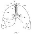
- Figure 2shows an anterior view of a pair of human lungs 110, 115 and a bronchial tree 120 that provides a fluid pathway into and out of the lungs 110, 115 from a trachea 125, as will be known to those skilled in the art.
- the term "fluid”can refer to a gas, a liquid, or a combination of gas(es) and liquid(s).
- Figure 2shows only a portion of the bronchial tree 120, which is described in more detail below with reference to Figure 5 .
- FIG. 1refers to relative directions or locations along a path defined from an entryway into the patient's body (e.g., the mouth or nose) to the patient's lungs.
- the path of airflow into the lungsgenerally begins at the patient's mouth or nose, travels through the trachea into one or more bronchial passageways, and terminates at some point in the patient's lungs.
- Figure 2shows a path 102 that travels through the trachea 125 and through a bronchial passageway into a location in the right lung 110.
- proximal directionrefers to the direction along such a path 102 that points toward the patient's mouth or nose and away from the patient's lungs.
- the proximal directionis generally the same as the expiration direction when the patient breathes.
- the arrow 104 in Figure 2points in the proximal or expiratory direction.
- the term "distal direction”refers to the direction along such a path 102 that points toward the patient's lung and away from the mouth or nose.
- the distal directionis generally the same as the inhalation or inspiratory direction when the patient breathes.
- the arrow 106 in Figure 2points in the distal or inhalation direction.
- the lungsinclude a right lung 110 and a left lung 115.
- the right lung 110includes lung regions comprised of three lobes, including a right upper lobe 130, a right middle lobe 135, and a right lower lobe 140.
- the lobes 130, 135, 140are separated by two interlobar fissures, including a right oblique fissure 126 and a right transverse fissure 128.
- the right oblique fissure 126separates the right lower lobe 140 from the right upper lobe 130 and from the right middle lobe 135.
- the right transverse fissure 128separates the right upper lobe 130 from the right middle lobe 135.
- the left lung 115includes lung regions comprised of two lobes, including the left upper lobe 150 and the left lower lobe 155.
- An interlobar fissure comprised of a left oblique fissure 145 of the left lung 115separates the left upper lobe 150 from the left lower lobe 155.
- the lobes 130, 135, 140, 150, 155are directly supplied air via respective lobar bronchi, as described in detail below.
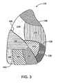
- FIG 3is a lateral view of the right lung 110.
- the right lung 110is subdivided into lung regions comprised of a plurality of bronchopulmonary segments. Each bronchopulmonary segment is directly supplied air by a corresponding segmental tertiary bronchus, as described below.
- the bronchopulmonary segments of the right lung 110include a right apical segment 210, a right posterior segment 220, and a right anterior segment 230, all of which are disposed in the right upper lobe 130.
- the right lung bronchopulmonary segmentsfurther include a right lateral segment 240 and a right medial segment 250, which are disposed in the right middle lobe 135.
- the right lower lobe 140includes bronchopulmonary segments comprised of a right superior segment 260, a right medial basal segment (which cannot be seen from the lateral view and is not shown in Figure 3 ), a right anterior basal segment 280, a right lateral basal segment 290, and a right posterior basal segment 295.
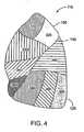
- Figure 4shows a lateral view of the left lung 115, which is subdivided into lung regions comprised of a plurality of bronchopulmonary segments.
- the bronchopulmonary segmentsinclude a left apical segment 310, a left posterior segment 320, a left anterior segment 330, a left superior segment 340, and a left inferior segment 350, which are disposed in the left lung upper lobe 150.
- the lower lobe 155 of the left lung 115includes bronchopulmonary segments comprised of a left superior segment 360, a left medial basal segment (which cannot be seen from the lateral view and is not shown in Figure 4 ), a left anterior basal segment 380, a left lateral basal segment 390, and a left posterior basal segment 395.
- Figure 5shows an anterior view of the trachea 125 and a portion of the bronchial tree 120, which includes a network of bronchial passageways, as described below.
- the trachea 125divides at a lower end into two bronchial passageways comprised of primary bronchi, including a right primary bronchus 410 that provides direct air flow to the right lung 110, and a left primary bronchus 415 that provides direct air flow to the left lung 115.
- Each primary bronchus 410, 415divides into a next generation of bronchial passageways comprised of a plurality of lobar bronchi.
- the right primary bronchus 410divides into a right upper lobar bronchus 417, a right middle lobar bronchus 420, and a right lower lobar bronchus 422.
- the left primary bronchus 415divides into a left upper lobar bronchus 425 and a left lower lobar bronchus 430.
- Each lobar bronchus, 417, 420, 422, 425, 430directly feeds fluid to a respective lung lobe, as indicated by the respective names of the lobar bronchi.
- the lobar bronchieach divide into yet another generation of bronchial passageways comprised of segmental bronchi, which provide air flow to the bronchopulmonary segments discussed above.
- a bronchial passagewaydefines an internal lumen through which fluid can flow to and from a lung or lung region.
- the diameter of the internal lumen for a specific bronchial passagewaycan vary based on the bronchial passageway's location in the bronchial tree (such as whether the bronchial passageway is a lobar bronchus or a segmental bronchus) and can also vary from patient to patient.
- the internal diameter of a bronchial passagewayis generally in the range of 3 millimeters (mm) to 10 mm, although the internal diameter of a bronchial passageway can be outside of this range.
- a bronchial passagewaycan have an internal diameter of well below 1 mm at locations deep within the lung.
- Figure 6shows a perspective view of a bronchial isolation device 610 that includes a frame 615, a valve member 620 mounted in the frame 615, and a membrane 625.
- the bronchial isolation device 610can be positioned within a bronchial passageway to regulate fluid flow through the bronchial passageway.
- Figure 7shows a side, perspective view of a first embodiment of the frame 615, which includes a retainer portion 715 and an integrally-connected valve protector portion 720.
- the frame 615is comprised of a plurality of interconnected struts 710 that collectively form the outer periphery of the bronchial isolation device 610. As shown in the front view of Figure 8 , at least some of the struts 710 are collectively arranged in an annular configuration such that the shape of the frame 615 approximates the internal shape of a bronchial passageway.
- the struts 710are arranged so as to form a plurality of diamond-shaped cells 712.
- the cellsare referred to generally using the reference numeral 712.
- Cells within the retainer portion 715are referred to as “retainer cells 712a” and cells within the valve protector portion 720 are referred to as “valve protector cells 712b.”
- the cells 712can vary in size and shape.
- the retainer cells 712aare longer and wider in size than the valve protector cells 712b.
- the size, shape and quantity of the struts 710 and the cells 712can vary.
- the struts 710can be arranged in a z-pattern or a "zig-zag" pattern.
- the retainer portion 715 of the frame 615has a diameter that is larger than the diameter of the valve protector portion 720.
- the diameter of the retainer portion 715is sufficiently large to cause the retainer portion 715 to press against and anchor to the walls of the bronchial passageway to secure the bronchial isolation device 610 in a fixed location relative to the bronchial passageway.
- Each retainer cell 712a of the frame 615may be shaped to have a curved, distal edge 725 and a curved, proximal edge 730 that both assist in anchoring the retainer portion 715 to the bronchial passageway, as described more fully below.
- Each cell 712ais attached to an adjacent cell 712b at a cell junction 735.
- the valve protector portion 720has valve protector cells 712b, which are smaller than the retainer cells 712a of the retainer portion 715 in order to compensate for the smaller diameter of the valve protector portion 720.
- Each valve protector cell 712bmay have a curved, distal edge 735 and a curved, proximal edge 740.
- the size and shape of the valve protector cells 712b and the retainer cells 712acan vary.
- the valve protector portion 720at least partially surrounds the valve member 620 to maintain a default shape of the valve member, as described more fully below.
- the valve protector portion 720can be rigid or flexible and it can be configured to collapse and expand.
- a plurality of linking struts 745connect the valve protector portion 720 to the retainer portion 715 of the frame 615.
- at least one linking strut 745connects each retainer cell 712a to each valve protector cell 712b.
- each linking strut 745has a first end that connects to the curved, proximal edge 730 of a respective retainer cell 712a.
- Each linking strut 745also has a second end that connects to a cell junction 735 between two valve protector cells 712b or to a distant point of a zig-zag strut of the valve protector portion 720.
- the linking struts 745extends in a longitudinal direction from the valve protector portion 720 to the retainer portion 715.
- the linking struts 745can be manufactured to be stiff or flexible.
- the linking struts 745curve radially outward from the valve protector portion 715 to provide the frame 615 with a smoothly-shaped transition between the retainer portion 715 and the valve protector portion 720 so as to eliminate sharp edges.
- the linking struts 745have a smooth, curved contour without sharp edges to lessen the likelihood of the frame 615 digging into the bronchial wall during removal of the bronchial isolation device 610.
- connection between the curved, proximal edges 730 of the retainer cells 712a and the first end of each linking strut 745eliminates the proximal edges 730 of the retainer cells 712a from hanging in midair, which reduces the likelihood of the proximal edges 730 digging into the bronchial wall during removal.
- the linking struts 745also provide a structural connection between the retainer portion 715 of the frame 615 and the distal edges 730 of the retainer cells 712a.
- the frame 615can transition between a contracted state and an expanded state. In the contracted state, the frame 615 has a diameter that is smaller than the diameter of the frame 615 in the expanded state.
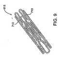
- Figure 9shows a perspective view of another embodiment of a frame 615 in the contracted state, wherein the struts 710 form a series of undulating loops that can be, for example, in a zig-zag pattern. The struts 710 are arranged close to one another so that the cells 712 are constricted and the frame 615 has a reduced diameter. (The frame 615 in Figure 9 is a different embodiment than the frame of Figure 7 .
- the frame 615 in Figure 9is the frame of Figure 10 in a contracted state.
- Figure 7shows the frame 615 in the expanded state, wherein the entire frame 615 is stretched radially-outward so that the struts 710 separate from one another to form enlarged cells 712.
- the struts 710can form at least two connected rows of undulating loops.
- the connected rows of undulating loopstransition to diamond-shaped cells in the expanded state. It should be appreciated that the pattern of the struts can vary in both the contracted and expanded states.
- the retainer portion 715 of the frame 615radially expands to a larger diameter than the valve protector portion 720 so that the frame takes on the shape shown in Figure 7 .
- the bronchial isolation device 610has a compressed profile that facilitates insertion of the bronchial isolation device 610 into a delivery device, such as a bronchoscope, and also facilitates insertion into a bronchial passageway.
- the frame 615is manufactured of a malleable material.
- the frame 615can be manually expanded to the anchoring state, such as by inserting an inflatable balloon inside the frame 615 once the bronchial.isolation device 610 is implanted in the bronchial passageway, and then inflating the balloon to expand the frame beyond the material's yield point into an interfering engagement with the wall of the bronchial passageway.
- the insertion statecan be achieved through a preconstraint of the frame 615 within the elastic range of the frame material. Once positioned in the bronchial passageway, the frame 615 can be released from constraint so that spring resilience causes it to expand into an anchoring state. Constraining tubes or other mechanisms may achieve the initial insertion state.
- the transition temperature of the frame 615could be at a predetermined temperature, such as below body temperature. Under such a circumstance, a frame 615 that is at a temperature below the transition temperature can be deformed into a shape that is suitable for insertion, and will stay in this unrecovered state until the temperature is brought above the transition temperature. The unrecovered state of the frame 615 would be in an insertion position with the frame 615 having a smaller diameter. Upon recovery of the frame material, the frame 615 would expand, such as when the frame achieves a predetermined temperature within the bronchial passageway.
- the frame 615can be manufactured of a variety of bio-compatible materials.
- the frame 615is manufactured of a superelastic material, such as Nitinol, that is heat-treated to attain the shape shown in Figure 7 .
- the entire frame 615is manufactured out of a single piece of tubing made out of Nitinol or some other material.
- Figure 9shows an isometric view of a tubular piece of material that has been cut into a pattern that forms the desired strut pattern. Once the material has been cut, such as through laser-cutting or chemical etching, the material is expanded and optionally heat treated so that it attains the shape shown in Figure 10 .
- the framemay be manufactured from a flat piece of material that is cut into a pattern that forms the desired strut pattern, rolled into an annular configuration and then the mating edges are welded, bonded or otherwise joined. The material, as before, is then expanded and optionally heat treated so that it attains the shape shown in Figure 10 .
- the frame 615can be manufactured of other materials, such as plastic or stainless steel
- Figure 10shows a perspective view of another embodiment of the frame 615 wherein the linking struts 745 are connected to different locations on the retainer portion 715 and valve protector portion 720 of the frame.
- the first end of the linking strut 745is connected to the retainer portion 715 at the cell junction 735 between a pair of retainer cells 712a.
- the second end of the linking strut 745is connected to a cell junction 735 between a pair of valve protector cells 712b.
- the curved, proximal edges 730 of the retainer cells 712aare cantilevered in that they are not connected to or supported by linking struts 745.
- valve protector portion 720 of the frame 615comprises a tube 1210 formed of a solid wall rather than a plurality of struts.
- the tube 1210can include at least one removal window 1215 that can be grasped by a removal device (such as a set of jaws) during removal of the bronchial isolation device 610 from a bronchial passageway.
- the retainer portion 710comprises a plurality of struts 710 that are shown arranged in a zig-zag pattern, although the struts 710 can also form cells, as in the previous embodiments, or can be in other patterns.
- the valve protector portion 720 comprised of the tube 1210does not undergo any expansion or contraction, but rather retains its size. However, the retainer portion 715 can expand and contract as in the previous embodiments.
- Figure 12shows another embodiment of the frame 615 (including the membrane 625) that includes two retainer portions including a proximal retainer portion 715a and a distal retainer portion 715b.
- a central valve protector portion 720is disposed in-between the proximal retainer portion 715a and the distal retainer portion 715b and connected thereto by linking struts 745.
- the retainer portions 715a,bhave larger diameters than the valve protector portion 720 so that the frame 615 has an hourglass-like shape. It should be appreciated that the diameter of the proximal retainer portion 715a is not necessarily equal to the diameter of the distal retainer portion 715b.
- the dual retainer portions 715a, 715bcan provide an increase in stability when the bronchial isolation device 610 is mounted in a bronchial passageway, as both retainer portions 715a, 715b provide independent anchors to the bronchial wall. Both retainer portions 715a, 715b also provide seals against the bronchial wall in which the bronchial isolation device is mounted. Thus, if the anchor or seal in one of the retainer portions weakens or fails, the other anchor portion 715a, 715b can compensate for the weakened or failed seal.
- bronchial isolation deviceIt is important to prevent the bronchial isolation device from migrating in either the proximal or the distal direction after implantation in the bronchial passageway. It has been determined that migration in the proximal (i.e., exhalation) direction can occur when the patient coughs, resulting in pressure buildup behind the bronchial isolation device. This can lead to migration or expulsion of the device from the bronchial passageway.
- One mitigating factor that can reduce the likelihood of this occurringis that the bronchial passageways are constricted by the pressure of the cough, and this can cause the passageway to tend to grip the device more firmly in place.
- exhalationis inherently difficult for patients with emphysema, and has the effect of reducing the pressure that can build up behind the device during exhalation.
- the exhalation flow produced by coughing or breathingwill preferentially flow through the valve, and will thus reduce the pressure that can build up behind the device.
- Migration in the distal (i.e., inhalation) directioncan occur when the patient takes a deep inhalation breath, which can result in the device being "sucked" deeper into the lung. This effect is exacerbated by the fact that the bronchial lumens expand when air is inhaled, and this can lead to a less secure retention of the device in the airway.
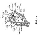
- Figures 13-16show embodiments of the frame 615 that include features that prevent or limit migration of the device in the proximal or distal direction once the device is implanted in a bronchial passageway.
- the frame 615includes retention prongs comprised of cross struts that resist migration of the bronchial isolation device in a bronchial passageway, such as by limiting the depth that the cell portions of the frame can penetrate into a bronchial wall in which the bronchial isolation device 610 is located.
- Figure 13shows the frame 615 in an expander, annular state, wherein the frame includes at least one distal cross strut 1410 and at least one proximal cross strut 1415.
- the cross struts 1410, 1415comprise additional struts or projections that have v-shape in the expanded state and extend outward between the struts of the frame 615.
- the cross struts 1410, 1415can be loop shaped in the contracted state.
- the cross struts 1410, 1415extend outward from the cells 712 at connection locations 1420, which serve as stopping points that limit the cells 712 from penetrating into a bronchial wall beyond a predetermined distance, as described in more detail below.
- the cross struts 1410, 1415also form additional cells 1425 that can be engaged with the membrane 625 to provide additional sealing capability between the frame 615 and the bronchial wall. It should be appreciated that the cross struts 1410, 1415 can be positioned at various locations on the frame beside that which is shown in Figure 13 .
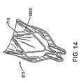
- Figure 14shows another embodiment of the frame 615 with retention prongs 1610 that project radially-outward from the struts 710 in the expanded state.
- the prongs 1610are bent so that they protrude radially-outward from the radial periphery of the retainer portion of the frame 615.
- the prongs 1610can at least partially sink in the bronchial wall tissue and prevent migration of the device in the distal direction.
- the retention prongs 1610limit migration in the distal direction by fixing the frame 615 to the bronchial wall and thus preventing the cells 712 from penetrating the bronchial wall tissue.
- FIG. 15shows a front view of the frame 615 and Figure 16 shows a cross-sectional view of the frame 615.
- the valve member 620is shown in Figure 16 mounted within the valve protector portion 720.
- Figure 16does not show the membrane 625 for clarity of illustration, although it should be appreciated that the membrane 625 would be attached to the frame 615 and the valve member 620 and would thereby secure the valve member 620 to the frame 615.
- the frame 615includes distal cross struts 1410 that form distal cells 1425 that can be smaller than the retainer cells 712a.
- the cells 1425can move and flex independently of the retainer cells 712a that form the remainder of the retainer section 715 of the frame 615. This allows different portions of the retainer sections to independently conform to the shape of a bronchial wall.
- the membrane 625is connected to the frame 615.
- Figure 17Ashows a cross-sectional view of a portion of the membrane 625 and a strut 710, cut along the line 17-17 of Figure 13 .
- the membrane 625can fully encapsulate the struts 710 of the frame 615 so that the membrane 625 is integrally attached to the frame 615.
- the encapsulation of the membrane 625 over the struts 710can be accomplished by using a dipping manufacturing process described below.
- the membrane 625can also be connected to the valve member 620.
- the membrane 625extends in a web-like manner between the struts 710 within the spaces of the cells 712 of the frame 615.
- the membrane 625can be stretched in tension across the cells, although this is not necessary.
- the membranehas a thickness T.
- the membrane 625generally bulges outwardly from the struts 710 in the region where the membrane 625 surrounds the struts.
- the thickness Tis not substantially larger than the diameter or thickness of the struts 710. In this manner, the membrane 625 does not substantially contribute to or increase the diameter of the frame 615.
- the membrane 625can be disposed over the entire frame 615, including both the retainer portion 715 and the valve protector portion 720, or the membrane can be disposed only over a portion of the frame, such as the enlarged-diameter retainer portion 715. It should be appreciated that the thickness T of the membrane can vary relative to the diameter of the struts 710 and that the thickness T need not be uniform across the entire membrane.
- FIG 17Bshows another embodiment of the configuration of the membrane 625 relative to the struts 710.
- the membrane 710does not entirely encapsulate the strut 710 but rather leaves a portion of the strut 710 uncovered or exposed.
- the membrane 710covers a radially-outward portion 1602 and sides of the strut 710 and does not cover a radially-inward portion 1604 of the struts 710.
- An inner surface 1606 of the membrane 625is positioned substantially flush with the radially-inward portion 1604 of the strut 710, thereby leaving the radially-inward portion 1604 exposed.
- Figure 17Cshows another embodiment of the configuration of the membrane 625 relative to the strut 710 wherein the membrane 625 does not entirely encapsulate the strut 710.
- the membranecovers the radially-inward portion 1604 but does not cover the radially-outward portion 1602 of the strut 710.
- An outer surface 1608 of the membrane 625is positioned substantially flush with the radially-outward portion 1602 of the strut 710, thereby leaving the radially-outward portion 1602 exposed.
- Figure 17Dshows yet another embodiment of the configuration of the membrane 625 relative to the strut 710.
- the membrane 625is mounted on one side of the strut 710 and does not encapsulate or surround the strut 710.
- Figure 17Dshows the membrane 625 mounted on the radially-inward portion 1604 of the strut 710 with the outer surface 1608 of the membrane juxtaposed with the radially-inward portion 1604.
- the membrane 625can also be mounted on the radially-outward portion 1602.
- the membrane 625can be mounted on the struts 710 in other manners and that the membrane 625 can encapsulate other portions of the struts and leave various portions of the struts 710 uncovered or exposed.
- the membrane 625is disposed over the entire retainer portion of the frame 615 such that the retainer portion can expand and contract without causing the membrane 625 to wrinkle against the bronchial wall when disposed in a bronchial passageway.
- the membrane 625can be thin and elastic so that the membrane 625 can expand along with the frame 615 without inhibiting the frame from exerting a sufficient radial force to grip the bronchial wall.
- the membrane 625does not inhibit the frame 615 from expanding or contracting, but rather expands and contracts according to any expansion or contraction of the frame 615.
- the membrane 625is desirably attached to the valve member 620 in a leak-free manner. That is, when the bronchial isolation device 610 is positioned in a bronchial passageway, fluid is prevented from flowing in-between the membrane 625 and the valve member, but must rather flow through a fluid-flow opening in the valve member 620.
- the membrane 625provides a fluid pathway into an entry mouth of the valve member that directs fluid in a bronchial passageway into the valve member, as described more fully below. It is not necessary that the membrane 625 completely cover the self-expanding valve protector section of the frame or that the membrane 625 completely cover the valve member 620.
- the membrane 625is firmly attached to the self-expanding, retainer portion 715 of the frame 615.
- the self-expanding retainer portion 715radially expands to sealingly anchor against the bronchial passageway wall.
- the sealcan be either between the membrane 625 and the bronchial wall or the frame 615 and the bronchial wall, as described more fully below.
- the bronchial isolation device 610seals inside the bronchial passageway, and flow of fluid around the bronchial isolation device 610 is prevented in a desired direction, such as the inhalation direction or in the exhalation direction.
- the bronchial isolation device 610also prevents flow-around the device in the exhalation direction, and the only flow that is allowed is through the valve member 620 in the exhalation direction.
- the self-expanding retainer portion 715 of the frame 615can be configured to allow fluid flowing in the exhalation direction to flow between the frame and the bronchial lumen wall as well as through the one-way valve, yet still prevent flow in the inhalation direction (either through the one-way valve or between the frame and the bronchial lumen wall).
- the flexible membrane 625can be thin so that it provides a relatively small amount of material that must be compressed when the bronchial isolation device 610 is in the compressed state.
- the membrane 625is contoured so as to increase the tendency of the membrane 625 to deform in a desired manner when the flow control device 610 is compressed.
- the thickness of the membrane 625can vary. In one embodiment, the membrane 625 has a thickness in the range of about 12.7 ⁇ m (0.0005 inch) to about 127 ⁇ m (0.005 inch), although other thickness outside this range are possible. In one embodiment, the membrane 625 has a thickness in the range of about 25.4 ⁇ m (0.001 inch) to about 254 ⁇ m (0.010 inch) In one embodiment, the thickness of the membrane is 76.2 ⁇ m (0.003 inch).
- the flexible membrane 625is formed of a biocompatible, flexible material, such as, for example, silicone, urethane, or a urethane/silicone composite. It should be appreciated that the membrane can be manufactured of other materials.
- the thin membrane 625can be manufactured according to a variety of processes.
- the membrane 625is manufactured by dipping a frame 615 into a dispersion 1810 of material used to manufacture the membrane 625.
- the dispersion 1810is located within a container 1815.
- the frame 615is first expanded, such as to the maximum possible diameter. This may be accomplished, for example, by mounting the frame 615 onto a mounting tool, such as a mandrel 1820 that is sized to receive the frame 615.
- the frame 615is then dipped into the dispersion 1810, such as in a dispersion of silicone, polyurethane or other polymer.
- the dispersion 1810is generated by mixing platinum cure silicone (uncured) with xylene.
- Another exemplary dispersion 1810comprises polyurethane dissolved in a solvent such as THF (tetrahydrofuran) or DMAC (dimethyl acetamide).
- the material of the dispersionadheres to the frame 615.
- the adhesion of a polymeric dispersion to a Nitinol framecan be enhanced with a primer such as a naphtha solution, which is especially useful for silicone membranes.
- the frame 615is removed from the dispersion so that a portion of the dispersion adheres to the frame 615. The dispersion is then allowed to cure and form the membrane 625.
- the thickness of the membrane 625can be controlled by adjusting the percent solids of the dispersion and the dip rate, or through the use of a dipping mandrel, such as the mandrel 1810 shown in Figure 18 .
- the dipped frame 615is rotated during the cure process about an axis that is either in a vertical orientation, a horizontal orientation, or both. The rotation of the frame 615 uniformly coats the dispersion about the frame 615. A variety of membrane thicknesses can be achieved using this process.
- One specific method of applying the dispersion 1810 to the frame 615is to dip the frame 615 into the dispersion 1810 (such as silicone), rotate the frame 615 to a horizontal position, and spin the frame 615 about a horizontal axis 1915 to evenly distribute the dispersion 1810 about the frame 615, as shown in Figure 19 .
- the frame 615is rotated to a vertical position that is upside down relative to the original dipped position, and spun about a vertical axis 2010 to continue to evenly distribute the dispersion, as shown in Figure 20 .
- the siliconecan then be cured in an oven.
- One curing methodincludes a two stage cure.
- the siliconeis cured at a first temperature for a first amount of time, such as at 140°F for 10 minutes.
- the siliconeis cured at a second temperature for a second amount, such as at 325°F for 10 minutes.
- the membrane 625can have a contoured shape that increases the tendency of the membrane to deform in a desired manner when the flow control device is compressed.
- the contours on the membrane 625can be created by dipping a stent that has a number of closed cells or perimeters, such as the cells 712. The dispersion fills the cells and creates a surface tension within the cells, which creates a dispersion membrane across each closed perimeter so that the membrane solidifies upon curing.
- the membrane contourscan be altered by conducting the dipping process with the stent placed over a formed tool or mandrel 1820.
- the mandrel 1820is manufactured of a material that does not adhere to the dispersion, such as PFA or some other fluoropolymer, in order to eliminate or reduce adhesion of the membrane 625 to the mandrel 1820.
- the shape of the membrane 625can be altered when the frame 615 is compressed for delivery.
- the mandrel 1820can be contoured to create concave surfaces on the membrane, wherein the concave surfaces will pleat inward during compression of the frame 615. This protects the membrane during compression, loading, and deployment of the bronchial isolation device.
- the membrane 625does not extend distally or proximally past the frame 615. That is, the membrane 625 is trimmed so that its distal edge follows the contours of the distal-most struts 710.
- the membrane 625extends distally past the struts 710 such that the membrane 625 has an untrimmed, distal edge 2102.
- the distal edge 2102is folded over and bonded to itself to form a flap. It can be folded over either inside or outside of the membrane 625.
- the folded-over flapprovides a thicker distal edge 2102 to reinforce the structural integrity of the distal edge 2102.
- the distal edge 2102can be structurally-reinforced by dipping the distal edge 2102 into a dispersion of the membrane material or by applying a section of the material to the distal edge 2102 with a syringe, and then curing the membrane 625 to form a reinforcing bead on the distal edge 2102.
- the valve member 620is disposed within the valve protection portion 720 of the frame 615.
- the valve member 620can be configured to either permit fluid flow in two directions (i.e., proximal and distal directions), permit fluid flow in only one direction (proximal or distal direction), or any combination of the above.
- the valve member 620can be configure such that when fluid flow, is permitted, it is only permitted above a certain pressure, referred to as the cracking pressure.
- the valve member 620is desirably formed of an elastic, biocompatible material, such as silicone, although other materials can be used.
- valve member 620comprises a one-way valve, it desirably has the following characteristics: low cracking pressure, high flow in the forward direction, rapid closure upon flow reversal, and complete sealing in the reverse direction, as discussed below.
- the cracking pressure in the exhalation directionis in the range of 0 to 254 mm (0 to 10 inches) of water. In another embodiment, the cracking pressure is in the range of 0 to 27mm (0 to 5 inches) of water. In another embodiment, the cracking pressure is in the range of 0 to 508mm (0 to 2 inch) of water. Given the 100% humidity conditions that exist in the lungs, these cracking pressures can be measured under similar or wet conditions in order to simulate the conditions of the lungs.
- the pressure differential across the valve at a flow of 50 ml/min in the exhalation directionis in the range of 0 to 101.6 mm (0 to 4 inches) of water.
- the pressure differential across the valve at a flow of 50 ml/min in the exhalation directionis in the range of 0 to 508 mm (0 to 2 inch) of water.
- the pressure differential across the valve at a flow of 50 ml/min in the exhalation directionis in the range of 0 to 25.4 mm (0 to 1 inches) of water.
- the responsiveness of the valveis a measure of how quickly the valve closes once flow through the valve in the exhalation direction is stopped. For example, a high-performing valve would close instantly when the valve encounters a reverse-direction flow and not allow any flow in the reverse direction back through the valve.
- a flow of 120 ml/minis sent in the exhalation direction of the valve, and then reversed to flow in the inhalation direction, the valve closes and seal completely in less than 4 seconds in one embodiment, in less than 2 seconds in another embodiment, and in less than 1 second in another embodiment.
- valve bronchial isolation devicesit is desirable for implanted one-way valve bronchial isolation devices to seal completely in the inhalation direction at all times after deployment in a bronchial passageway under all conditions.
- the valvedesirably stays sealed regardless of the orientation of the patient's body, regardless of the rotational orientation of the valve in the bronchial lumen, regardless of whether or not the implanted device is being compressed by external compression of the bronchial lumen, regardless of whether or not there is mucus present on the valve seal surfaces, etc.
- the valveshould remain sealed even if there is little or no pressure differential across the valve
- the valve member 620comprises a duckbill valve that permits flow in one direction and prevents or restricts flow in a second direction.
- Figures 23-25show an embodiment of a valve member 620 comprised of a duckbill valve 2310 that can be used in the bronchial isolation device 610.
- the duckbill valve 2310includes a tubular base 2315 that has an outer diameter that fits within the annular valve protector portion 720 of the frame 615.
- the duckbill valve 2310includes a pair of opposed, inclined walls 2320 having ends that meet at lips 2325.
- the lips 2325meet at two opposed corners.
- the walls 2320can move with respect to one another so as to separate at the lips 2325 and form an opening through which fluid can travel.
- the walls 2320When exposed to fluid flow in a first direction (represented by the arrow 2330 in Figure 23 ) at the cracking pressure, the walls 2320 separate from one another to form the opening. When exposed to fluid flow in a second direction (represented by the arrow 2335 in Figure 23 ), the walls 2320 remain closed and prevent fluid from flowing through the duckbill valve 2310.
- the valve protector portion 720 of the frame 615provides structural support to the valve member 620 and serves to prevent the valve member 620 from being deformed to the extent that the performance of the valve member 620 is adversely affected.
- a bronchial passagewaycan constrict or otherwise change shape during inhalation, exhalation, or cough.
- the valve protector portion 720substantially shields the valve member 620 from excessive deformation when the bronchial passageway changes shape.
- the valve member 620can optionally include a reinforcement member 2202 comprised of a curved or looped wire that extends between the two corners of the lips and around the duckbill valve 2310 or other type of valve. For clarity of illustration, the reinforcement member is only shown in Figure 24 .
- the curved wireis rigid so as to provide structural protection to the valve 2310, such as to maintain the distance between the corners of the lips, in the event that the valve 2310 is exposed to forces that might deform the valve 2310.
- the reinforcement member 2202may be used in combination with the valve protector portion 720 of the frame, of may be used as a substitute for the valve protector portion 720.
- the walls 2320have an outwardly-domed outer surface 2342 and as a leading edge 1910 that forms an outward curve.
- the curved-shape of the leading edge 1910provides a longer lips 2325 than the lip for a straight leading edge, such as the straight leading edge 2502 of the duckbill valve 2504 shown in Figures 26 and 27 .
- the resultis that for a given valve size, the flow rate at a given differential pressure across the lips is higher for a curved leading edge valve than for a straight leading edge valve.
- Table 1lists the pressure drop across two duckbill valves, including a duckbill valve with a curved leading edge (i.e., a curved mouth) and a diameter of about 0.128 inches and a duckbill valve with a straight leading edge (i.e., a straight mouth) and a diameter of about 2.95 mm (0.116 inches). As shown in Table 1, even though the curved-mouth valve has a smaller diameter, the pressure drop across the curved-mouth valve is lower than the straight mouth valve at both 50 ml/min and 500 ml/min. Table 1: Curved vs.
- the curved-mouth duckbill valveprovides a higher flow rate than the straight-mouthed duckbill valve, which makes the curved mouth duckbill valve particularly well suited for use in a one-way valve bronchial isolation device.
- the cracking pressure of a duckbill valvecan be altered by changing the angle between the faces of the two lips of the valves.
- the cracking pressurewill be reduced if this angle is reduced, and the cracking pressure will be increased if this angle is increased.
- the angleis reduced, the length of the valve increases, and this should be taken into account if a very short valve is desired.
- FIGs 28A and 28Bshows an embodiment of a one-way duckbill valve 2702 that provides a controlled flow in a reverse direction.
- the valve 2702behaves as a one-way valve in the forward direction (represented by the arrow 2704 in Figure 28A ) in that the valve 2702 allows free flow of fluid through the valve at or above the valve's cracking pressure.
- the valve 2702also allows a small, controlled rate of flow in the reverse direction (represented by the arrow 2706 in Figure 28A ).
- the duckbill valve 2702includes a small flow channel 2708 that extends through the lips of the valve, as best shown in the enlarged view of Figure 28B .
- the flow channel 2708allows fluid to flow in the reverse direction through the lips.
- the rate of flowis a function of the diameter and length of the flow channel 2708.
- valve member 620can comprise valve types other than a duckbill valve.
- the one-way duckbill valvecould be replaced with another type of one-way valve, such as a flap valve, a Heimlich valve, a tri-lobe duckbill valve or other multi-lobe valves, a diaphragm valve, a ball valve, etc.
- the one-way valvecan be replaced with a blocking element to prevent flow through the device in either direction, or a two-way valve to allow controlled flow in both directions, or one-way or two-way valves that are designed to allow the passage of a catheter to suction, inject therapeutic substances or otherwise treat the isolated lung region distal to the implanted bronchial isolation device.
- Figure 29shows a cross-sectional view of the flow control device 610 employing the embodiment of the frame 615 shown in Figures 15 and 16 .
- the valve member 620is mounted within the valve protector portion 720 of the frame 615.
- the membrane 625is attached to the valve member 620 at one or more locations to secure the valve member 620 to the frame 615.
- the valve memberis positioned such that an entry mouth 2903 is located at a distal region of the valve protector portion 720 and an exit mouth 2905 is located at a proximal region.
- the valve protector portion 720at least partially surrounds the valve member 620 to maintain a default shape of the valve member 620.
- valve protector portion 720protects the valve member 620 from deformation.
- the default shape of the valve member 620can be a closed configuration that prohibits fluid flow or the default shape can be some other default shape.
- the membrane 625is positioned in a web-like manner within the cells 712.
- the membrane 625covers or is connected to at least a portion of the frame 615.
- the membranecovers at least a portion of the retainer portion 715 and can also cover at least a portion of the valve protector portion 720.
- the membrane 625can cover the entire retainer portion 715 or it can cover a portion of the retainer portion 715.
- the membrane 625can cover the entire valve protector portion 720 or it can cover a portion of the valve protector portion 720.
- the membrane 625defines a fluid pathway that is open at a distal end of the frame 615 and that leads into the entry mouth 2903 of the valve 620.
- the general outer contour of the fluid pathwayis represented by a bold line 2907 in Figure 29 .
- the membrane 625follows the outer contour of the frame 615 such that the fluid pathway is generally cylindrical in this portion of the frame 615.
- the fluid pathwayit is not necessary that the fluid pathway be cylindrical as long as it leads into the entry mouth 2903 of the valve member 620.
- the membranecover the entire bronchial isolation device 610 as long as the membrane forms the fluid pathway.
- the outer contour of the membrane 625slopes radially inward (as exhibited by the bold lines 2911) moving toward the entry mouth 2903 of the valve member 620. In this manner, the membrane 625 forms a funnel-shaped fluid pathway that leads into the valve member 620.
- the membrane 625also forms radially-extending fins 2914 between the outer membrane wall of the funnel-shaped fluid pathway and the linking struts 745.
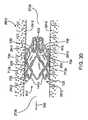
- Figure 30shows a cross-sectional view of bronchial passageway 2910 having interior walls 2915 that define a lumen of the bronchial passageway 2910.
- fluidscan travel to and from a region of the lung through the lumen of the bronchial passageway 2910.
- the embodiment of the bronchial isolation device 610 of Figure 29is shown positioned within the bronchial passageway 2910.
- the bronchial isolation device 610is shown in Figure 30 with the membrane 625 trimmed along the distal edge of the frame 615.
- the frame 615When the bronchial isolation device 610 is positioned within the bronchial passageway 2910, the frame 615 is in an expanded state so that it exerts a radial force against the interior walls 2915, as represented by the arrows 2912 in Figure 30 .
- the radial forcecauses the frame 615 to press against the bronchial wall 2915 with a pressure sufficient to retain the bronchial isolation device 610 in a fixed position relative to the bronchial passageway.
- the distal edges 725 of the retainer cells 712aare positioned such that they lodge against the interior walls 2915 and inhibit the bronchial isolation device 610 from migrating in the distal direction 206.
- the proximal edges 730 of the retainer cells 712aare attached to the linking struts 745.
- the linking struts 745provide a smooth transition between the retainer section and the valve protector section of the frame 615.
- the linking struts 745also lessen any sharpness of the proximal edges 730 of the retainer cells 712a and prevent the proximal edges 730 from penetrating into the bronchial wall 2915 if the bronchial isolation device 610 is pulled in the proximal direction during removal.
- the linking struts 745assist in radially constricting the retainer section of the frame 615 during removal of the bronchial isolation device 610.
- the linking struts 745transfer the radial constriction to the retainer section of the frame 615.
- the frame 615can optionally include one or more distal cross struts 1410 and one or more proximal cross struts 1415.
- the cross struts 1410, 1415function to limit the distance that the cells 712 can penetrate into the bronchial wall 2915.
- Figure 31shows the bronchial isolation device 610 after it has migrated in the distal direction 206 such that some of the distal edges 725 of the retainer cells 712a have penetrated into the bronchial wall 2915.
- the connection point 3010 between the distal cross strut 1410 and the cell 712aprovides a stopping point that will prevent the retainer cell 712a from penetrating any deeper beyond the connection point 3010.
- the expanded frame 615presses against the bronchial wall 2915 so that the bronchial isolation device 610 sealingly engages the bronchial wall 2915 around the entire circumference of the bronchial isolation device 610.
- the sealcan be formed between the frame 615 and the bronchial wall 2915, between the membrane 625 and the bronchial wall 2915, between both the membrane 625/frame 615 and the bronchial wall 2915, or any combination thereof.
- Figure 32Ashows an enlarged view of the portion of the flow control device 610 that forms a seal with the bronchial wall 2915.
- the membrane 625is positioned between a frame strut 710 and the bronchial wall 2915 such that the membrane 625 seals with the bronchial wall 2915.
- the situation shown in Figure 32Acorresponds to use of the frame/membrane configuration shown in Figures 17A, 17B .
- both the membrane 625 and the frame strut 710seal with the bronchial wall 2915.
- the situation shown in Figure 32Bcorresponds to use of the frame/membrane configuration shown in Figures 17C .
- the frame strut 710seals with the bronchial wall 2915 but the membrane 625 does not necessarily seal with or contact the bronchial wall 2915.
- the situation shown in Figure 32Ccorresponds to use of the frame/membrane configuration shown in Figures 17D .
- the frame 615is sealed with the bronchial wall 2915. It should be appreciated that the seal can occur at any location along the frame 615 as long as the membrane 625 provides a fluid pathway between the location of the seal and the valve member 620. As mentioned, the cross struts 1410 create additional cells that permit the frame to flex at different locations along its length. In this manner, the struts that form the cells can form independent and redundant seals with the bronchial wall 2915.
- the frame 615 and/or the membrane 625provide a seal that prevents fluid from flowing between the interior walls 2915 and the bronchial isolation device 610.
- the membrane 625engages with the portion of the bronchial isolation device that is sealed to the bronchial wall 2915 such that the fluid pathway formed by the membrane directs fluid into the valve member 620 so that fluid must flow through the valve member 620 in order to flow from a proximal side 2730 of the bronchial isolation device 610 to a distal side 2735 or vice-versa.
- the sealing engagement between the bronchial isolation device 610 and the bronchial wall 2915prevents fluid from flowing around the periphery of the bronchial isolation device 610, thereby forcing fluid flow to occur through the membrane path and into the valve member 620.
- the membrane 625provides a fluid pathway into the valve member 620. It is not necessary for the membrane 625 to cover the entire bronchial isolation device as long as the membrane 625 forms a pathway from the location of the seal to the entry mouth of the valve member 620.
- bronchial isolation device 610can be modified to permit such limited flow.
- the bronchial isolation device 610can be deployed to a desired location in a bronchial passageway according to a variety of methods.
- the bronchial isolation devicemay be is coupled to the distal end of a delivery catheter, which is then inserted through the patient's mouth or nose, into the trachea, and to the location in the bronchial passageway.
- the bronchial isolation device 610is then uncoupled from the delivery catheter such that it is positioned at a desired location in the bronchial passageway.
- a delivery catheter 3102can be deployed using a bronchoscope 3104, which in an exemplary embodiment has a steering mechanism 3106, a shaft 3108, a working channel entry port 3112, and a visualization eyepiece 3115.
- the bronchoscope 3104has been passed into a patient's trachea 125 and guided into the right primary bronchus 510 according to well-known methods.
- the delivery catheter 3102is then inserted into the bronchoscope through the working channel entry port 3112 and fed into the working channel so the distal end 3120 of the delivery catheter (and the attached bronchial isolation device 610) protrude out of the distal end of the bronchoscope.
- the bronchial isolation device 610is then released from the delivery catheter so that the frame 615 expands and anchors at a desired location, as shown in Figure 1 .
Landscapes
- Health & Medical Sciences (AREA)
- Life Sciences & Earth Sciences (AREA)
- Surgery (AREA)
- Biomedical Technology (AREA)
- Engineering & Computer Science (AREA)
- General Health & Medical Sciences (AREA)
- Animal Behavior & Ethology (AREA)
- Vascular Medicine (AREA)
- Heart & Thoracic Surgery (AREA)
- Veterinary Medicine (AREA)
- Public Health (AREA)
- Molecular Biology (AREA)
- Reproductive Health (AREA)
- Nuclear Medicine, Radiotherapy & Molecular Imaging (AREA)
- Medical Informatics (AREA)
- Cardiology (AREA)
- Oral & Maxillofacial Surgery (AREA)
- Transplantation (AREA)
- Physics & Mathematics (AREA)
- Optics & Photonics (AREA)
- Prostheses (AREA)
- Infusion, Injection, And Reservoir Apparatuses (AREA)
- External Artificial Organs (AREA)
- Media Introduction/Drainage Providing Device (AREA)
Abstract
Description
- This invention relates generally to a flow control device according to the preamble of claim 1 for use in performing pulmonary procedures and, more particularly, to devices and procedures for treating lung diseases.
- Pulmonary diseases, such as chronic obstructive pulmonary disease, (COPD), reduce the ability of one or both lungs to fully expel air during the exhalation phase of the breathing cycle. The term "Chronic Obstructive Pulmonary Disease" (COPD) refers to a group of diseases that share a major symptom, dyspnea. Such diseases are accompanied by chronic or recurrent obstruction to air flow within the lung. Because of the increase in environmental pollutants, cigarette smoking, and other noxious exposures, the incidence of COPD has increased dramatically in the last few decades and now ranks as a major cause of activity-restricting or bed-confining disability in the United States. COPD can include such disorders as chronic bronchitis, bronchiectasis, asthma, and emphysema. While each has distinct anatomic and clinical considerations, many patients may have overlapping characteristics of damage at both the acinar (as seen in emphysema) and the bronchial (as seen in bronchitis) levels.
- Emphysema is a condition of the lung characterized by the abnormal permanent enlargement of the airspaces distal to the terminal bronchiole, accompanied by the destruction of their walls, and without obvious fibrosis. It is known that emphysema and other pulmonary diseases reduce the ability of one or both lungs to fully expel air during the exhalation phase of the breathing cycle. One of the effects of such diseases is that the diseased lung tissue is less elastic than healthy lung tissue, which is one factor that prevents full exhalation of air. During breathing, the diseased portion of the lung does not fully recoil due to the diseased (e.g., emphysematic) lung tissue being less elastic than healthy tissue. Consequently, the diseased lung tissue exerts a relatively low driving force, which results in the diseased lung expelling less air volume than a healthy lung.
- The problem is further compounded by the diseased, less elastic tissue that surrounds the very narrow airways that lead to the alveoli, which are the air sacs where oxygen-carbon dioxide exchange occurs. The diseased tissue has less tone than healthy tissue and is typically unable to maintain the narrow airways open until the end of the exhalation cycle. This traps air in the lungs and exacerbates the already-inefficient breathing cycle. The trapped air causes the tissue to become hyper-expanded and no longer able to effect efficient oxygen-carbon dioxide exchange.
- In addition, hyper-expanded, diseased lung tissue occupies more of the pleural space than healthy lung tissue. In most cases, a portion of the lung is diseased while the remaining part is relatively healthy and, therefore, still able to somewhat efficiently carry out oxygen exchange. By taking up more of the pleural space, the hyper-expanded lung tissue reduces the amount of space available to accommodate the healthy, functioning lung tissue. As a result, the hyper-expanded lung tissue causes inefficient breathing due to its own reduced functionality and because it adversely affects the functionality of adjacent relatively healthier tissue.
- Lung reduction surgery is a conventional method of treating emphysema. According to the lung reduction procedure, a diseased portion of the lung is surgically removed, which makes more of the pleural space available to accommodate the functioning, healthy portions of the lung. The lung is typically accessed through a median stemotomy or small lateral thoracotomy. A portion of the lung, typically the periphery of the upper lobe, is freed from the chest wall and then resected, e.g., by a stapler lined with bovine pericardium to reinforce the lung tissue adjacent the cut line and also to prevent air or blood leakage. The chest is then closed and tubes are inserted to remove air and fluid from the pleural cavity. The conventional surgical approach is relatively traumatic and invasive, and, like most surgical procedures, is not a viable option for all patients.
- Some recently proposed treatments include the use of devices that isolate a diseased region of the lung in order to reduce the volume of the diseased region, such as by collapsing the diseased lung region. According to such treatments, isolation devices are implanted in airways feeding the targeted region of the lung to regulate fluid flow to the diseased lung region in order to fluidly isolate the region of the lung. These implanted isolation devices can be, for example, one-way valves that allow flow in the exhalation direction only, occluders or plugs that prevent flow in either direction, or two-way valves that Control flow in both directions. However, such devices are still in the development stages. Thus, there is much need for improvement in the design and functionality of such isolation devices.
US5954766 discloses a body fluid flow control device comprising a resilient seal, a frame extending within a portion of the resilient seal which includes a passageway extending through the frame, wherein the frame can be expanded to anchor the device in position in a body duct, a valve body and a valve support located about the whole valve body.WO 01/66190 - In view of the foregoing, there is a need for an improved device for regulating fluid flow to a diseased lung region.
- Dislcosed is a device for regulating fluid flow to and from a region of a patient's lung, such as to achieve a desired fluid flow dynamic to a lung region during respiration and/or to induce collapse in one or more lung regions. In accordance with the invention as defined in claim 1, there is disclosed a flow control device for a bronchial passageway. The flow control device comprises a valve member that regulates fluid flow through the flow control device, the valve having a default shape. The device further comprises a frame coupled to the valve member, the frame including a valve protector region that at least partially surrounds the valve member to maintain the default shape formed from a plurality of interconnected struts the valve protector region being collapsible from an expanded state to a contracted state; and a retainer region connected to the valve protector region, the retainer region being formed of a plurality of interconnected struts configured to engage an interior wall of the bronchial passageway to retain the flow control device in a fixed location therein. The retainer region is movable from a contracted state suitable for introduction into the bronchial passageway to an expanded state suitable for engaging the interior wall of the bronchial passageway wherein the diameter of the retainer region in the expanded state is larger than the diameter of the valve protector region in the expanded state. The device further comprises a membrane covering at least a portion of the retainer region, wherein at least a portion of the flow control device forms a seal with the interior wall of the bronchial passageway when the flow control device is implanted in the bronchial passageway, and wherein the membrane provides a fluid pathway from the seal to the valve member to direct fluid flowing through the bronchial passageway into the valve member.
- The device further comprises at least one linking strut that links the valve protector region to the retainer region, the at least one linking strut having a curved contour to provide the frame with a smooth transition between the valve protector region and the retainer region.
- The device may further comprise at least one retention prong extending from the frame and configured to engage the interior wall of the bronchial passageway to resist migration therein.
- Other features and advantages of the present invention should be apparent from the following description of various embodiments, which illustrate, by way of example, the principles of the invention.
Figure 1 shows an anterior view of a pair of human lungs and a bronchial tree with a bronchial isolation device implanted in a bronchial passageway to bronchially isolate a region of the lung.Figure 2 shows an anterior view of a pair of human lungs and a bronchial tree.Figure 3 shows a lateral view of the right lung.Figure 4 shows a lateral view of the left lung.Figure 5 shows an anterior view of the trachea and a portion of the bronchial tree.Figure 6 shows a perspective view of a bronchial isolation device.Figure 7 shows a side view of a frame of the bronchial isolation device.Figure 8 shows a front view of the frame ofFigure 7 .Figure 9 shows the frame ofFigure 10 in a contracted state.Figure 10 shows another embodiment of the frame of the bronchial isolation device.Figure 11 shows another embodiment of the frame of the bronchial isolation device.Figure 12 shows another embodiment of a bronchial isolation device including a frame with dual retainer portions.Figure 13 shows an embodiment of the frame with cross struts, the frame in an expanded, annular state.Figure 14 shows another embodiment of the frame with retention prongs.Figure 15 shows a front view of another embodiment of the frame.Figure 16 shows a cross-sectional, side view of the frame ofFigure 16 along line 16-16 ofFigure 15 .Figure 17A-17D each show a cross-sectional view of a portion of a frame strut and an embodiment of the membrane of the bronchial isolation device, the view along the line 17-17 ofFigure 13 .Figure 18 shows a step in the process of forming a membrane on the frame of the bronchial isolation device.Figure 19 shows another step in the process of forming a membrane on the frame of the bronchial isolation device.Figure 20 shows another step in the process of forming a membrane on the frame of the bronchial isolation device.Figure 21 shows an embodiment of the flow control device having an untrimmed membrane edge.Figure 22 shows an embodiment of the flow control device having a reinforced membrane edge.Figure 23 shows a perspective view of a duckbill valve member of the bronchial isolation device.Figure 24 shows a top view of the duckbill valve member ofFigure 23 .Figure 25 shows a cross-sectional, side view of the duckbill valve member ofFigure 23 .Figure 26 shows a perspective view of another embodiment of a duckbill valve member with a straight leading edge.Figure 27 shows a top view of the duckbill valve member ofFigure 26 .Figure 28A shows a perspective view of an embodiment of a one-way duckbill valve that provides a controlled flow in a reverse direction.Figure 28B shows an enlarged, perspective view of a mouth region of the valve ofFigure 28A .Figure 29 shows a cross-sectional view of the bronchial isolation device employing the frame ofFigure 15 and 16 .Figure 30 shows a bronchial isolation device deployed in a bronchial passageway.Figure 31 shows a bronchial isolation device deployed in a bronchial passageway and partially embedded in a bronchial wall of the passageway.Figure 32A-32C each show an enlarged view of the portion of the flow control device that forms a seal with the bronchial wall.Figure 33 shows a bronchoscope deployed within a bronchial tree of a patient for delivering a bronchial isolation device into a bronchial passageway.- Unless defined otherwise, all technical and scientific terms used herein have the same meaning as is commonly understood by one of skill in the art to which the invention(s) belong. Disclosed are various devices for treating bronchopulmonary diseases.
- Disclosed are various embodiments of
bronchial isolation devices 610 that can be used to isolate a diseased region of the lung in order to modify the air flow to the lung region or to achieve volume reduction or collapse of the lung region. One or more of thebronchial isolation devices 610 are implanted in bronchial passageways that feed fluid to a targeted region of the lung. Thebronchial isolation devices 610 block or regulate fluid flow to the diseased lung region through one or more bronchial passageways that feed air to the targeted lung region. - As shown in
Figure 1 , the bronchial isolation of the targeted lung region is accomplished by implanting abronchial isolation device 610 into abronchial passageway 15 that feeds air to a targetedlung region 20. Thebronchial isolation device 610 regulates airflow through thebronchial passageway 15 in which the bronchial isolation device 10 is implanted. Various embodiments of bronchial isolation devices are described herein. - Throughout this disclosure, reference is made to the term "lung region". As used herein, the term "lung region" refers to a defined division or portion of a lung. For purposes of example, lung regions are described herein with reference to human lungs, wherein some exemplary lung regions include lung lobes and lung segments. Thus, the term "lung region" as used herein can refer, for example, to a lung lobe or a lung segment. Such nomenclature conforms to nomenclature for portions of the lungs that are known to those skilled in the art. However, it should be appreciated that the term "lung region" does not necessarily refer to a lung lobe or a lung segment, but can refer to some other defined division or portion of a human or non-human lung.
Figure 2 shows an anterior view of a pair ofhuman lungs bronchial tree 120 that provides a fluid pathway into and out of thelungs trachea 125, as will be known to those skilled in the art. As used herein, the term "fluid" can refer to a gas, a liquid, or a combination of gas(es) and liquid(s). For clarity of illustration,Figure 2 shows only a portion of thebronchial tree 120, which is described in more detail below with reference toFigure 5 .- Throughout this description, certain terms are used that refer to relative directions or locations along a path defined from an entryway into the patient's body (e.g., the mouth or nose) to the patient's lungs. The path of airflow into the lungs generally begins at the patient's mouth or nose, travels through the trachea into one or more bronchial passageways, and terminates at some point in the patient's lungs. For example,
Figure 2 shows apath 102 that travels through thetrachea 125 and through a bronchial passageway into a location in theright lung 110. The term "proximal direction" refers to the direction along such apath 102 that points toward the patient's mouth or nose and away from the patient's lungs. In other words, the proximal direction is generally the same as the expiration direction when the patient breathes. Thearrow 104 inFigure 2 points in the proximal or expiratory direction. The term "distal direction" refers to the direction along such apath 102 that points toward the patient's lung and away from the mouth or nose. The distal direction is generally the same as the inhalation or inspiratory direction when the patient breathes. Thearrow 106 inFigure 2 points in the distal or inhalation direction. - The lungs include a
right lung 110 and aleft lung 115. Theright lung 110 includes lung regions comprised of three lobes, including a rightupper lobe 130, a rightmiddle lobe 135, and a rightlower lobe 140. Thelobes right oblique fissure 126 and a righttransverse fissure 128. Theright oblique fissure 126 separates the rightlower lobe 140 from the rightupper lobe 130 and from the rightmiddle lobe 135. The righttransverse fissure 128 separates the rightupper lobe 130 from the rightmiddle lobe 135. - As shown in
Figure 2 , theleft lung 115 includes lung regions comprised of two lobes, including the leftupper lobe 150 and the leftlower lobe 155. An interlobar fissure comprised of aleft oblique fissure 145 of theleft lung 115 separates the leftupper lobe 150 from the leftlower lobe 155. Thelobes Figure 3 is a lateral view of theright lung 110. Theright lung 110 is subdivided into lung regions comprised of a plurality of bronchopulmonary segments. Each bronchopulmonary segment is directly supplied air by a corresponding segmental tertiary bronchus, as described below. The bronchopulmonary segments of theright lung 110 include a rightapical segment 210, aright posterior segment 220, and a rightanterior segment 230, all of which are disposed in the rightupper lobe 130. The right lung bronchopulmonary segments further include a rightlateral segment 240 and a rightmedial segment 250, which are disposed in the rightmiddle lobe 135. The rightlower lobe 140 includes bronchopulmonary segments comprised of a rightsuperior segment 260, a right medial basal segment (which cannot be seen from the lateral view and is not shown inFigure 3 ), a right anteriorbasal segment 280, a right lateralbasal segment 290, and a right posteriorbasal segment 295.Figure 4 shows a lateral view of theleft lung 115, which is subdivided into lung regions comprised of a plurality of bronchopulmonary segments. The bronchopulmonary segments include a leftapical segment 310, aleft posterior segment 320, a leftanterior segment 330, a leftsuperior segment 340, and a leftinferior segment 350, which are disposed in the left lungupper lobe 150. Thelower lobe 155 of theleft lung 115 includes bronchopulmonary segments comprised of a leftsuperior segment 360, a left medial basal segment (which cannot be seen from the lateral view and is not shown inFigure 4 ), a left anteriorbasal segment 380, a left lateralbasal segment 390, and a left posteriorbasal segment 395.Figure 5 shows an anterior view of thetrachea 125 and a portion of thebronchial tree 120, which includes a network of bronchial passageways, as described below. In the context of describing the lung, the terms "pathway" and "lumen" are used interchangeably herein. Thetrachea 125 divides at a lower end into two bronchial passageways comprised of primary bronchi, including a rightprimary bronchus 410 that provides direct air flow to theright lung 110, and a leftprimary bronchus 415 that provides direct air flow to theleft lung 115. Eachprimary bronchus primary bronchus 410 divides into a right upperlobar bronchus 417, a right middlelobar bronchus 420, and a right lowerlobar bronchus 422. The leftprimary bronchus 415 divides into a left upperlobar bronchus 425 and a left lowerlobar bronchus 430. Each lobar bronchus, 417, 420, 422, 425, 430 directly feeds fluid to a respective lung lobe, as indicated by the respective names of the lobar bronchi. The lobar bronchi each divide into yet another generation of bronchial passageways comprised of segmental bronchi, which provide air flow to the bronchopulmonary segments discussed above.- As is known to those skilled in the art, a bronchial passageway defines an internal lumen through which fluid can flow to and from a lung or lung region. The diameter of the internal lumen for a specific bronchial passageway can vary based on the bronchial passageway's location in the bronchial tree (such as whether the bronchial passageway is a lobar bronchus or a segmental bronchus) and can also vary from patient to patient. However, the internal diameter of a bronchial passageway is generally in the range of 3 millimeters (mm) to 10 mm, although the internal diameter of a bronchial passageway can be outside of this range. For example, a bronchial passageway can have an internal diameter of well below 1 mm at locations deep within the lung.
Figure 6 shows a perspective view of abronchial isolation device 610 that includes aframe 615, avalve member 620 mounted in theframe 615, and amembrane 625. As mentioned above, thebronchial isolation device 610 can be positioned within a bronchial passageway to regulate fluid flow through the bronchial passageway.Figure 7 shows a side, perspective view of a first embodiment of theframe 615, which includes aretainer portion 715 and an integrally-connectedvalve protector portion 720. Theframe 615 is comprised of a plurality ofinterconnected struts 710 that collectively form the outer periphery of thebronchial isolation device 610. As shown in the front view ofFigure 8 , at least some of thestruts 710 are collectively arranged in an annular configuration such that the shape of theframe 615 approximates the internal shape of a bronchial passageway.- With reference to
Figure 7 , thestruts 710 are arranged so as to form a plurality of diamond-shapedcells 712. The cells are referred to generally using thereference numeral 712. Cells within theretainer portion 715 are referred to as "retainer cells 712a" and cells within thevalve protector portion 720 are referred to as "valve protector cells 712b." Thecells 712 can vary in size and shape. For example, theretainer cells 712a are longer and wider in size than thevalve protector cells 712b. It should be appreciated that the size, shape and quantity of thestruts 710 and thecells 712 can vary. For example, thestruts 710 can be arranged in a z-pattern or a "zig-zag" pattern. - The
retainer portion 715 of theframe 615 has a diameter that is larger than the diameter of thevalve protector portion 720. When thebronchial isolation device 610 is deployed within a bronchial passageway, the diameter of theretainer portion 715 is sufficiently large to cause theretainer portion 715 to press against and anchor to the walls of the bronchial passageway to secure thebronchial isolation device 610 in a fixed location relative to the bronchial passageway. Eachretainer cell 712a of theframe 615 may be shaped to have a curved,distal edge 725 and a curved,proximal edge 730 that both assist in anchoring theretainer portion 715 to the bronchial passageway, as described more fully below. Eachcell 712a is attached to anadjacent cell 712b at acell junction 735. - With reference still to
Figure 7 , thevalve protector portion 720 hasvalve protector cells 712b, which are smaller than theretainer cells 712a of theretainer portion 715 in order to compensate for the smaller diameter of thevalve protector portion 720. Eachvalve protector cell 712b may have a curved,distal edge 735 and a curved,proximal edge 740. As mentioned, the size and shape of thevalve protector cells 712b and theretainer cells 712a can vary. Thevalve protector portion 720 at least partially surrounds thevalve member 620 to maintain a default shape of the valve member, as described more fully below. Thevalve protector portion 720 can be rigid or flexible and it can be configured to collapse and expand. - A plurality of linking
struts 745 connect thevalve protector portion 720 to theretainer portion 715 of theframe 615. In the embodiment shown inFigure 7 , at least one linkingstrut 745 connects eachretainer cell 712a to eachvalve protector cell 712b. In this regard, each linkingstrut 745 has a first end that connects to the curved,proximal edge 730 of arespective retainer cell 712a. Each linkingstrut 745 also has a second end that connects to acell junction 735 between twovalve protector cells 712b or to a distant point of a zig-zag strut of thevalve protector portion 720. The linking struts 745 extends in a longitudinal direction from thevalve protector portion 720 to theretainer portion 715. The linking struts 745 can be manufactured to be stiff or flexible. - The linking struts 745 curve radially outward from the
valve protector portion 715 to provide theframe 615 with a smoothly-shaped transition between theretainer portion 715 and thevalve protector portion 720 so as to eliminate sharp edges. As can be seen inFigure 7 , the linking struts 745 have a smooth, curved contour without sharp edges to lessen the likelihood of theframe 615 digging into the bronchial wall during removal of thebronchial isolation device 610. In particular, the connection between the curved,proximal edges 730 of theretainer cells 712a and the first end of each linkingstrut 745 eliminates theproximal edges 730 of theretainer cells 712a from hanging in midair, which reduces the likelihood of theproximal edges 730 digging into the bronchial wall during removal. The linking struts 745 also provide a structural connection between theretainer portion 715 of theframe 615 and thedistal edges 730 of theretainer cells 712a. This allows thedistal edges 730 of theretainer cells 712a to be radially constricted by pulling or constricting thevalve protector cells 712b, which assists removal of the bronchialflow control device 610 from a bronchial passageway, as described in more detail below. - The
frame 615 can transition between a contracted state and an expanded state. In the contracted state, theframe 615 has a diameter that is smaller than the diameter of theframe 615 in the expanded state.Figure 9 shows a perspective view of another embodiment of aframe 615 in the contracted state, wherein thestruts 710 form a series of undulating loops that can be, for example, in a zig-zag pattern. Thestruts 710 are arranged close to one another so that thecells 712 are constricted and theframe 615 has a reduced diameter. (Theframe 615 inFigure 9 is a different embodiment than the frame ofFigure 7 . Theframe 615 inFigure 9 is the frame ofFigure 10 in a contracted state.)Figure 7 shows theframe 615 in the expanded state, wherein theentire frame 615 is stretched radially-outward so that thestruts 710 separate from one another to formenlarged cells 712. Thus, in the contracted state, thestruts 710 can form at least two connected rows of undulating loops. The connected rows of undulating loops transition to diamond-shaped cells in the expanded state. It should be appreciated that the pattern of the struts can vary in both the contracted and expanded states. - During transition from the contracted state to the expanded state, the
retainer portion 715 of theframe 615 radially expands to a larger diameter than thevalve protector portion 720 so that the frame takes on the shape shown inFigure 7 . When theframe 615 is in the compressed state, thebronchial isolation device 610 has a compressed profile that facilitates insertion of thebronchial isolation device 610 into a delivery device, such as a bronchoscope, and also facilitates insertion into a bronchial passageway. - Various mechanisms can be employed to achieve the expanded and contracted states of the
frame 615. In one embodiment, theframe 615 is manufactured of a malleable material. Theframe 615 can be manually expanded to the anchoring state, such as by inserting an inflatable balloon inside theframe 615 once thebronchial.isolation device 610 is implanted in the bronchial passageway, and then inflating the balloon to expand the frame beyond the material's yield point into an interfering engagement with the wall of the bronchial passageway. - Another mechanism that can be employed to achieve the two-state frame size is spring resilience. The insertion state can be achieved through a preconstraint of the
frame 615 within the elastic range of the frame material. Once positioned in the bronchial passageway, theframe 615 can be released from constraint so that spring resilience causes it to expand into an anchoring state. Constraining tubes or other mechanisms may achieve the initial insertion state. - Another mechanism that can be used to achieve both the contracted and the expanded states of the
frame 615 is the shape memory characteristics of certain materials such as certain nickel titanium alloys, including Nitinol. The transition temperature of theframe 615 could be at a predetermined temperature, such as below body temperature. Under such a circumstance, aframe 615 that is at a temperature below the transition temperature can be deformed into a shape that is suitable for insertion, and will stay in this unrecovered state until the temperature is brought above the transition temperature. The unrecovered state of theframe 615 would be in an insertion position with theframe 615 having a smaller diameter. Upon recovery of the frame material, theframe 615 would expand, such as when the frame achieves a predetermined temperature within the bronchial passageway. - The
frame 615 can be manufactured of a variety of bio-compatible materials. In one embodiment, theframe 615 is manufactured of a superelastic material, such as Nitinol, that is heat-treated to attain the shape shown inFigure 7 . In one embodiment, theentire frame 615 is manufactured out of a single piece of tubing made out of Nitinol or some other material.Figure 9 shows an isometric view of a tubular piece of material that has been cut into a pattern that forms the desired strut pattern. Once the material has been cut, such as through laser-cutting or chemical etching, the material is expanded and optionally heat treated so that it attains the shape shown inFigure 10 . - Alternatively, the frame may be manufactured from a flat piece of material that is cut into a pattern that forms the desired strut pattern, rolled into an annular configuration and then the mating edges are welded, bonded or otherwise joined. The material, as before, is then expanded and optionally heat treated so that it attains the shape shown in
Figure 10 . It should be appreciated that theframe 615 can be manufactured of other materials, such as plastic or stainless steel Figure 10 shows a perspective view of another embodiment of theframe 615 wherein the linking struts 745 are connected to different locations on theretainer portion 715 andvalve protector portion 720 of the frame. For each linkingstrut 745, the first end of the linkingstrut 745 is connected to theretainer portion 715 at thecell junction 735 between a pair ofretainer cells 712a. The second end of the linkingstrut 745 is connected to acell junction 735 between a pair ofvalve protector cells 712b. Thus, the curved,proximal edges 730 of theretainer cells 712a are cantilevered in that they are not connected to or supported by linkingstruts 745.Figure 11 shows yet another embodiment of theframe 615. In this embodiment,valve protector portion 720 of theframe 615 comprises atube 1210 formed of a solid wall rather than a plurality of struts. Thetube 1210 can include at least oneremoval window 1215 that can be grasped by a removal device (such as a set of jaws) during removal of thebronchial isolation device 610 from a bronchial passageway. Theretainer portion 710 comprises a plurality ofstruts 710 that are shown arranged in a zig-zag pattern, although thestruts 710 can also form cells, as in the previous embodiments, or can be in other patterns. Thevalve protector portion 720 comprised of thetube 1210 does not undergo any expansion or contraction, but rather retains its size. However, theretainer portion 715 can expand and contract as in the previous embodiments.Figure 12 shows another embodiment of the frame 615 (including the membrane 625) that includes two retainer portions including aproximal retainer portion 715a and adistal retainer portion 715b. A centralvalve protector portion 720 is disposed in-between theproximal retainer portion 715a and thedistal retainer portion 715b and connected thereto by linkingstruts 745. Theretainer portions 715a,b have larger diameters than thevalve protector portion 720 so that theframe 615 has an hourglass-like shape. It should be appreciated that the diameter of theproximal retainer portion 715a is not necessarily equal to the diameter of thedistal retainer portion 715b.- The
dual retainer portions bronchial isolation device 610 is mounted in a bronchial passageway, as bothretainer portions retainer portions other anchor portion - It is important to prevent the bronchial isolation device from migrating in either the proximal or the distal direction after implantation in the bronchial passageway. It has been determined that migration in the proximal (i.e., exhalation) direction can occur when the patient coughs, resulting in pressure buildup behind the bronchial isolation device. This can lead to migration or expulsion of the device from the bronchial passageway. One mitigating factor that can reduce the likelihood of this occurring is that the bronchial passageways are constricted by the pressure of the cough, and this can cause the passageway to tend to grip the device more firmly in place. In addition, exhalation is inherently difficult for patients with emphysema, and has the effect of reducing the pressure that can build up behind the device during exhalation. In addition, the exhalation flow produced by coughing or breathing will preferentially flow through the valve, and will thus reduce the pressure that can build up behind the device. Migration in the distal (i.e., inhalation) direction can occur when the patient takes a deep inhalation breath, which can result in the device being "sucked" deeper into the lung. This effect is exacerbated by the fact that the bronchial lumens expand when air is inhaled, and this can lead to a less secure retention of the device in the airway. In view of the foregoing, it is desirable to have features on the
frame 615 to prevent or limit migration of the device after implantation, such as to prevent or limit migration in the distal direction. Figures 13-16 show embodiments of theframe 615 that include features that prevent or limit migration of the device in the proximal or distal direction once the device is implanted in a bronchial passageway. In one embodiment, theframe 615 includes retention prongs comprised of cross struts that resist migration of the bronchial isolation device in a bronchial passageway, such as by limiting the depth that the cell portions of the frame can penetrate into a bronchial wall in which thebronchial isolation device 610 is located.Figure 13 shows theframe 615 in an expander, annular state, wherein the frame includes at least onedistal cross strut 1410 and at least oneproximal cross strut 1415. The cross struts 1410, 1415 comprise additional struts or projections that have v-shape in the expanded state and extend outward between the struts of theframe 615. The cross struts 1410, 1415 can be loop shaped in the contracted state. The cross struts 1410, 1415 extend outward from thecells 712 atconnection locations 1420, which serve as stopping points that limit thecells 712 from penetrating into a bronchial wall beyond a predetermined distance, as described in more detail below. The cross struts 1410, 1415 also formadditional cells 1425 that can be engaged with themembrane 625 to provide additional sealing capability between theframe 615 and the bronchial wall. It should be appreciated that the cross struts 1410, 1415 can be positioned at various locations on the frame beside that which is shown inFigure 13 .Figure 14 shows another embodiment of theframe 615 withretention prongs 1610 that project radially-outward from thestruts 710 in the expanded state. Theprongs 1610 are bent so that they protrude radially-outward from the radial periphery of the retainer portion of theframe 615. When thebronchial isolation device 610 is implanted in a bronchial passageway, theprongs 1610 can at least partially sink in the bronchial wall tissue and prevent migration of the device in the distal direction. Unlike the distal cross struts 1410 that limit migration in the distal direction by limiting the depth of penetration of thecells 712, theretention prongs 1610 limit migration in the distal direction by fixing theframe 615 to the bronchial wall and thus preventing thecells 712 from penetrating the bronchial wall tissue.- With reference to
Figures 15 and 16 , there is shown another embodiment of theframe 615.Figure 15 shows a front view of theframe 615 andFigure 16 shows a cross-sectional view of theframe 615. Thevalve member 620 is shown inFigure 16 mounted within thevalve protector portion 720.Figure 16 does not show themembrane 625 for clarity of illustration, although it should be appreciated that themembrane 625 would be attached to theframe 615 and thevalve member 620 and would thereby secure thevalve member 620 to theframe 615. Theframe 615 includes distal cross struts 1410 that formdistal cells 1425 that can be smaller than theretainer cells 712a. Thecells 1425 can move and flex independently of theretainer cells 712a that form the remainder of theretainer section 715 of theframe 615. This allows different portions of the retainer sections to independently conform to the shape of a bronchial wall. - With reference again to
Figure 13 , themembrane 625 is connected to theframe 615.Figure 17A shows a cross-sectional view of a portion of themembrane 625 and astrut 710, cut along the line 17-17 ofFigure 13 . As shown in the embodiment ofFigure 17A , themembrane 625 can fully encapsulate thestruts 710 of theframe 615 so that themembrane 625 is integrally attached to theframe 615. The encapsulation of themembrane 625 over thestruts 710 can be accomplished by using a dipping manufacturing process described below. Themembrane 625 can also be connected to thevalve member 620. - As shown in
Figure 13 , themembrane 625 extends in a web-like manner between thestruts 710 within the spaces of thecells 712 of theframe 615. Themembrane 625 can be stretched in tension across the cells, although this is not necessary. As shown inFigure 17A , the membrane has a thickness T. Themembrane 625 generally bulges outwardly from thestruts 710 in the region where themembrane 625 surrounds the struts. In one embodiment, the thickness T is not substantially larger than the diameter or thickness of thestruts 710. In this manner, themembrane 625 does not substantially contribute to or increase the diameter of theframe 615. Themembrane 625 can be disposed over theentire frame 615, including both theretainer portion 715 and thevalve protector portion 720, or the membrane can be disposed only over a portion of the frame, such as the enlarged-diameter retainer portion 715. It should be appreciated that the thickness T of the membrane can vary relative to the diameter of thestruts 710 and that the thickness T need not be uniform across the entire membrane. Figure 17B shows another embodiment of the configuration of themembrane 625 relative to thestruts 710. In this embodiment, themembrane 710 does not entirely encapsulate thestrut 710 but rather leaves a portion of thestrut 710 uncovered or exposed. In this regard, themembrane 710 covers a radially-outward portion 1602 and sides of thestrut 710 and does not cover a radially-inward portion 1604 of thestruts 710. Aninner surface 1606 of themembrane 625 is positioned substantially flush with the radially-inward portion 1604 of thestrut 710, thereby leaving the radially-inward portion 1604 exposed.Figure 17C shows another embodiment of the configuration of themembrane 625 relative to thestrut 710 wherein themembrane 625 does not entirely encapsulate thestrut 710. In this embodiment, the membrane covers the radially-inward portion 1604 but does not cover the radially-outward portion 1602 of thestrut 710. Anouter surface 1608 of themembrane 625 is positioned substantially flush with the radially-outward portion 1602 of thestrut 710, thereby leaving the radially-outward portion 1602 exposed.Figure 17D shows yet another embodiment of the configuration of themembrane 625 relative to thestrut 710. In this embodiment, themembrane 625 is mounted on one side of thestrut 710 and does not encapsulate or surround thestrut 710.Figure 17D shows themembrane 625 mounted on the radially-inward portion 1604 of thestrut 710 with theouter surface 1608 of the membrane juxtaposed with the radially-inward portion 1604. It should be appreciated that themembrane 625 can also be mounted on the radially-outward portion 1602. Furthermore, it should be appreciated that themembrane 625 can be mounted on thestruts 710 in other manners and that themembrane 625 can encapsulate other portions of the struts and leave various portions of thestruts 710 uncovered or exposed.- In one embodiment, the
membrane 625 is disposed over the entire retainer portion of theframe 615 such that the retainer portion can expand and contract without causing themembrane 625 to wrinkle against the bronchial wall when disposed in a bronchial passageway. Themembrane 625 can be thin and elastic so that themembrane 625 can expand along with theframe 615 without inhibiting the frame from exerting a sufficient radial force to grip the bronchial wall. Thus, themembrane 625 does not inhibit theframe 615 from expanding or contracting, but rather expands and contracts according to any expansion or contraction of theframe 615. - The
membrane 625 is desirably attached to thevalve member 620 in a leak-free manner. That is, when thebronchial isolation device 610 is positioned in a bronchial passageway, fluid is prevented from flowing in-between themembrane 625 and the valve member, but must rather flow through a fluid-flow opening in thevalve member 620. In this regard, themembrane 625 provides a fluid pathway into an entry mouth of the valve member that directs fluid in a bronchial passageway into the valve member, as described more fully below. It is not necessary that themembrane 625 completely cover the self-expanding valve protector section of the frame or that themembrane 625 completely cover thevalve member 620. - The
membrane 625 is firmly attached to the self-expanding,retainer portion 715 of theframe 615. When thebronchial isolation device 610 is properly positioned within a bronchial passageway, the self-expandingretainer portion 715 radially expands to sealingly anchor against the bronchial passageway wall. It should be appreciated that the seal can be either between themembrane 625 and the bronchial wall or theframe 615 and the bronchial wall, as described more fully below. Thus, thebronchial isolation device 610 seals inside the bronchial passageway, and flow of fluid around thebronchial isolation device 610 is prevented in a desired direction, such as the inhalation direction or in the exhalation direction. In general, thebronchial isolation device 610 also prevents flow-around the device in the exhalation direction, and the only flow that is allowed is through thevalve member 620 in the exhalation direction. However, the self-expandingretainer portion 715 of theframe 615 can be configured to allow fluid flowing in the exhalation direction to flow between the frame and the bronchial lumen wall as well as through the one-way valve, yet still prevent flow in the inhalation direction (either through the one-way valve or between the frame and the bronchial lumen wall). - The
flexible membrane 625 can be thin so that it provides a relatively small amount of material that must be compressed when thebronchial isolation device 610 is in the compressed state. In one embodiment, themembrane 625 is contoured so as to increase the tendency of themembrane 625 to deform in a desired manner when theflow control device 610 is compressed. The thickness of themembrane 625 can vary. In one embodiment, themembrane 625 has a thickness in the range of about 12.7 µm (0.0005 inch) to about 127 µm (0.005 inch), although other thickness outside this range are possible. In one embodiment, themembrane 625 has a thickness in the range of about 25.4 µm (0.001 inch) to about 254 µm (0.010 inch) In one embodiment, the thickness of the membrane is 76.2 µm (0.003 inch). - The
flexible membrane 625 is formed of a biocompatible, flexible material, such as, for example, silicone, urethane, or a urethane/silicone composite. It should be appreciated that the membrane can be manufactured of other materials. - The
thin membrane 625 can be manufactured according to a variety of processes. In an exemplary process, described with reference toFigure 18 , themembrane 625 is manufactured by dipping aframe 615 into adispersion 1810 of material used to manufacture themembrane 625. Thedispersion 1810 is located within acontainer 1815. According to the exemplary process, theframe 615 is first expanded, such as to the maximum possible diameter. This may be accomplished, for example, by mounting theframe 615 onto a mounting tool, such as amandrel 1820 that is sized to receive theframe 615. Theframe 615 is then dipped into thedispersion 1810, such as in a dispersion of silicone, polyurethane or other polymer. In one exemplary embodiment, thedispersion 1810 is generated by mixing platinum cure silicone (uncured) with xylene. Anotherexemplary dispersion 1810 comprises polyurethane dissolved in a solvent such as THF (tetrahydrofuran) or DMAC (dimethyl acetamide). - When the
frame 615 is dipped into thedispersion 1810, the material of the dispersion adheres to theframe 615. The adhesion of a polymeric dispersion to a Nitinol frame can be enhanced with a primer such as a naphtha solution, which is especially useful for silicone membranes. After dipping theframe 615, theframe 615 is removed from the dispersion so that a portion of the dispersion adheres to theframe 615. The dispersion is then allowed to cure and form themembrane 625. - The thickness of the
membrane 625 can be controlled by adjusting the percent solids of the dispersion and the dip rate, or through the use of a dipping mandrel, such as themandrel 1810 shown inFigure 18 . In one embodiment, the dippedframe 615 is rotated during the cure process about an axis that is either in a vertical orientation, a horizontal orientation, or both. The rotation of theframe 615 uniformly coats the dispersion about theframe 615. A variety of membrane thicknesses can be achieved using this process. - One specific method of applying the
dispersion 1810 to theframe 615 is to dip theframe 615 into the dispersion 1810 (such as silicone), rotate theframe 615 to a horizontal position, and spin theframe 615 about ahorizontal axis 1915 to evenly distribute thedispersion 1810 about theframe 615, as shown inFigure 19 . After a period of time, such as about three minutes, theframe 615 is rotated to a vertical position that is upside down relative to the original dipped position, and spun about avertical axis 2010 to continue to evenly distribute the dispersion, as shown inFigure 20 . The silicone can then be cured in an oven. One curing method includes a two stage cure. In the first stage, the silicone is cured at a first temperature for a first amount of time, such as at 140°F for 10 minutes. In the second stage, the silicone is cured at a second temperature for a second amount, such as at 325°F for 10 minutes. - As mentioned, the
membrane 625 can have a contoured shape that increases the tendency of the membrane to deform in a desired manner when the flow control device is compressed. The contours on themembrane 625 can be created by dipping a stent that has a number of closed cells or perimeters, such as thecells 712. The dispersion fills the cells and creates a surface tension within the cells, which creates a dispersion membrane across each closed perimeter so that the membrane solidifies upon curing. The membrane contours can be altered by conducting the dipping process with the stent placed over a formed tool ormandrel 1820. In one embodiment, themandrel 1820 is manufactured of a material that does not adhere to the dispersion, such as PFA or some other fluoropolymer, in order to eliminate or reduce adhesion of themembrane 625 to themandrel 1820. By using this method, the shape of themembrane 625 can be altered when theframe 615 is compressed for delivery. For example, themandrel 1820 can be contoured to create concave surfaces on the membrane, wherein the concave surfaces will pleat inward during compression of theframe 615. This protects the membrane during compression, loading, and deployment of the bronchial isolation device. - In the embodiment shown in
Figure 6 , themembrane 625 does not extend distally or proximally past theframe 615. That is, themembrane 625 is trimmed so that its distal edge follows the contours of the distal-most struts 710. In another embodiment, shown inFigure 21 using the embodiment of the frame ofFigures 15 and 16 , themembrane 625 extends distally past thestruts 710 such that themembrane 625 has an untrimmed,distal edge 2102. In another embodiment of the untrimmed-membrane, shown inFigure 22 , thedistal edge 2102 is folded over and bonded to itself to form a flap. It can be folded over either inside or outside of themembrane 625. The folded-over flap provides a thickerdistal edge 2102 to reinforce the structural integrity of thedistal edge 2102. Alternately, thedistal edge 2102 can be structurally-reinforced by dipping thedistal edge 2102 into a dispersion of the membrane material or by applying a section of the material to thedistal edge 2102 with a syringe, and then curing themembrane 625 to form a reinforcing bead on thedistal edge 2102. - With reference to
Figure 6 , thevalve member 620 is disposed within thevalve protection portion 720 of theframe 615. Thevalve member 620 can be configured to either permit fluid flow in two directions (i.e., proximal and distal directions), permit fluid flow in only one direction (proximal or distal direction), or any combination of the above. Thevalve member 620 can be configure such that when fluid flow, is permitted, it is only permitted above a certain pressure, referred to as the cracking pressure. Thevalve member 620 is desirably formed of an elastic, biocompatible material, such as silicone, although other materials can be used. - When the
valve member 620 comprises a one-way valve, it desirably has the following characteristics: low cracking pressure, high flow in the forward direction, rapid closure upon flow reversal, and complete sealing in the reverse direction, as discussed below. - During exhalation from a lung that is damaged by emphysema or COPD, the amount of driving pressure that can be generated to force air out of the lung is quite low. Given this condition, in order for air to be exhaled from the isolated lung region, it is desirable that the cracking pressure in the exhalation direction be as low as possible. In one embodiment, the cracking pressure is in the range of 0 to 254 mm (0 to 10 inches) of water. In another embodiment, the cracking pressure is in the range of 0 to 27mm (0 to 5 inches) of water. In another embodiment, the cracking pressure is in the range of 0 to 508mm (0 to 2 inch) of water. Given the 100% humidity conditions that exist in the lungs, these cracking pressures can be measured under similar or wet conditions in order to simulate the conditions of the lungs.
- Rapid exhalation of air from the region of the lung isolated behind a one-way or two-way valve device is important for the rapid and complete collapse of the isolated lung portion, or for the maximal improvement in flow dynamics in the absence of collapse. Thus, the higher the flow through the bronchial isolation device at a given pressure across the device, the better the performance of the device. To this end, in one embodiment, the pressure differential across the valve at a flow of 50 ml/min in the exhalation direction is in the range of 0 to 101.6 mm (0 to 4 inches) of water. In another embodiment, the pressure differential across the valve at a flow of 50 ml/min in the exhalation direction is in the range of 0 to 508 mm (0 to 2 inch) of water. In another embodiment, the pressure differential across the valve at a flow of 50 ml/min in the exhalation direction is in the range of 0 to 25.4 mm (0 to 1 inches) of water.
- The responsiveness of the valve is a measure of how quickly the valve closes once flow through the valve in the exhalation direction is stopped. For example, a high-performing valve would close instantly when the valve encounters a reverse-direction flow and not allow any flow in the reverse direction back through the valve. When a flow of 120 ml/min is sent in the exhalation direction of the valve, and then reversed to flow in the inhalation direction, the valve closes and seal completely in less than 4 seconds in one embodiment, in less than 2 seconds in another embodiment, and in less than 1 second in another embodiment.
- It is desirable for implanted one-way valve bronchial isolation devices to seal completely in the inhalation direction at all times after deployment in a bronchial passageway under all conditions. The valve desirably stays sealed regardless of the orientation of the patient's body, regardless of the rotational orientation of the valve in the bronchial lumen, regardless of whether or not the implanted device is being compressed by external compression of the bronchial lumen, regardless of whether or not there is mucus present on the valve seal surfaces, etc. In addition, the valve should remain sealed even if there is little or no pressure differential across the valve
- In one embodiment, the
valve member 620 comprises a duckbill valve that permits flow in one direction and prevents or restricts flow in a second direction.Figures 23-25 show an embodiment of avalve member 620 comprised of aduckbill valve 2310 that can be used in thebronchial isolation device 610. Theduckbill valve 2310 includes atubular base 2315 that has an outer diameter that fits within the annularvalve protector portion 720 of theframe 615. As best shown inFigures 23 and 25 , theduckbill valve 2310 includes a pair of opposed,inclined walls 2320 having ends that meet atlips 2325. Thelips 2325 meet at two opposed corners. Thewalls 2320 can move with respect to one another so as to separate at thelips 2325 and form an opening through which fluid can travel. When exposed to fluid flow in a first direction (represented by thearrow 2330 inFigure 23 ) at the cracking pressure, thewalls 2320 separate from one another to form the opening. When exposed to fluid flow in a second direction (represented by thearrow 2335 inFigure 23 ), thewalls 2320 remain closed and prevent fluid from flowing through theduckbill valve 2310. - The
valve protector portion 720 of theframe 615 provides structural support to thevalve member 620 and serves to prevent thevalve member 620 from being deformed to the extent that the performance of thevalve member 620 is adversely affected. For example, a bronchial passageway can constrict or otherwise change shape during inhalation, exhalation, or cough. Thevalve protector portion 720 substantially shields thevalve member 620 from excessive deformation when the bronchial passageway changes shape. Thevalve member 620 can optionally include areinforcement member 2202 comprised of a curved or looped wire that extends between the two corners of the lips and around theduckbill valve 2310 or other type of valve. For clarity of illustration, the reinforcement member is only shown inFigure 24 . The curved wire is rigid so as to provide structural protection to thevalve 2310, such as to maintain the distance between the corners of the lips, in the event that thevalve 2310 is exposed to forces that might deform thevalve 2310. Thereinforcement member 2202 may be used in combination with thevalve protector portion 720 of the frame, of may be used as a substitute for thevalve protector portion 720. - With reference to
Figures 23-25 , thewalls 2320 have an outwardly-domedouter surface 2342 and as aleading edge 1910 that forms an outward curve. The curved-shape of theleading edge 1910 provides alonger lips 2325 than the lip for a straight leading edge, such as the straightleading edge 2502 of theduckbill valve 2504 shown inFigures 26 and 27 . The result is that for a given valve size, the flow rate at a given differential pressure across the lips is higher for a curved leading edge valve than for a straight leading edge valve. Table 1 lists the pressure drop across two duckbill valves, including a duckbill valve with a curved leading edge (i.e., a curved mouth) and a diameter of about 0.128 inches and a duckbill valve with a straight leading edge (i.e., a straight mouth) and a diameter of about 2.95 mm (0.116 inches). As shown in Table 1, even though the curved-mouth valve has a smaller diameter, the pressure drop across the curved-mouth valve is lower than the straight mouth valve at both 50 ml/min and 500 ml/min.Table 1: Curved vs. Straight Duckbill Valve Pressure Drop Valve Type Valve Diameter, inches Pressure Drop Across Valve, in-H2O 50 ml/min 500 ml/min Straight mouth 325 mm (0.128) 0.5 2.8 Curved Mouth 215 mm (0.116) 0.4 2.4 - Thus, the curved-mouth duckbill valve provides a higher flow rate than the straight-mouthed duckbill valve, which makes the curved mouth duckbill valve particularly well suited for use in a one-way valve bronchial isolation device. As mentioned above, for bronchial implantation, the higher the flow rate once the valve is cracked open, the better the performance of the valve.
- It has been determined that the cracking pressure of a duckbill valve can be altered by changing the angle between the faces of the two lips of the valves. The cracking pressure will be reduced if this angle is reduced, and the cracking pressure will be increased if this angle is increased. As the angle is reduced, the length of the valve increases, and this should be taken into account if a very short valve is desired.
- There may be situations where a controlled reverse flow through a one-way valve might be desirable.
Figures 28A and 28B shows an embodiment of a one-way duckbill valve 2702 that provides a controlled flow in a reverse direction. Thevalve 2702 behaves as a one-way valve in the forward direction (represented by thearrow 2704 inFigure 28A ) in that thevalve 2702 allows free flow of fluid through the valve at or above the valve's cracking pressure. Thevalve 2702 also allows a small, controlled rate of flow in the reverse direction (represented by thearrow 2706 inFigure 28A ). In this regard, theduckbill valve 2702 includes asmall flow channel 2708 that extends through the lips of the valve, as best shown in the enlarged view ofFigure 28B . Theflow channel 2708 allows fluid to flow in the reverse direction through the lips. The rate of flow is a function of the diameter and length of theflow channel 2708. - It should be appreciated that the
valve member 620 can comprise valve types other than a duckbill valve. For example, the one-way duckbill valve could be replaced with another type of one-way valve, such as a flap valve, a Heimlich valve, a tri-lobe duckbill valve or other multi-lobe valves, a diaphragm valve, a ball valve, etc. In addition, the one-way valve can be replaced with a blocking element to prevent flow through the device in either direction, or a two-way valve to allow controlled flow in both directions, or one-way or two-way valves that are designed to allow the passage of a catheter to suction, inject therapeutic substances or otherwise treat the isolated lung region distal to the implanted bronchial isolation device. Figure 29 shows a cross-sectional view of theflow control device 610 employing the embodiment of theframe 615 shown inFigures 15 and 16 . Thevalve member 620 is mounted within thevalve protector portion 720 of theframe 615. Themembrane 625 is attached to thevalve member 620 at one or more locations to secure thevalve member 620 to theframe 615. The valve member is positioned such that anentry mouth 2903 is located at a distal region of thevalve protector portion 720 and anexit mouth 2905 is located at a proximal region. Thevalve protector portion 720 at least partially surrounds thevalve member 620 to maintain a default shape of thevalve member 620. For example, if the bronchial passageway deforms while thebronchial isolation device 610 is mounted therein, thevalve protector portion 720 protects thevalve member 620 from deformation. The default shape of thevalve member 620 can be a closed configuration that prohibits fluid flow or the default shape can be some other default shape.- The
membrane 625 is positioned in a web-like manner within thecells 712. Themembrane 625 covers or is connected to at least a portion of theframe 615. The membrane covers at least a portion of theretainer portion 715 and can also cover at least a portion of thevalve protector portion 720. Themembrane 625 can cover theentire retainer portion 715 or it can cover a portion of theretainer portion 715. In addition, themembrane 625 can cover the entirevalve protector portion 720 or it can cover a portion of thevalve protector portion 720. - The
membrane 625 defines a fluid pathway that is open at a distal end of theframe 615 and that leads into theentry mouth 2903 of thevalve 620. The general outer contour of the fluid pathway is represented by abold line 2907 inFigure 29 . In thevalve retainer portion 715, themembrane 625 follows the outer contour of theframe 615 such that the fluid pathway is generally cylindrical in this portion of theframe 615. However, it is not necessary that the fluid pathway be cylindrical as long as it leads into theentry mouth 2903 of thevalve member 620. Moreover, it is not necessary that the membrane cover the entirebronchial isolation device 610 as long as the membrane forms the fluid pathway. Moving toward thevalve member 625, the outer contour of themembrane 625 slopes radially inward (as exhibited by the bold lines 2911) moving toward theentry mouth 2903 of thevalve member 620. In this manner, themembrane 625 forms a funnel-shaped fluid pathway that leads into thevalve member 620. Themembrane 625 also forms radially-extendingfins 2914 between the outer membrane wall of the funnel-shaped fluid pathway and the linking struts 745. Figure 30 shows a cross-sectional view ofbronchial passageway 2910 havinginterior walls 2915 that define a lumen of thebronchial passageway 2910. As is known to those skilled in the art, fluids can travel to and from a region of the lung through the lumen of thebronchial passageway 2910. The embodiment of thebronchial isolation device 610 ofFigure 29 is shown positioned within thebronchial passageway 2910. Thebronchial isolation device 610 is shown inFigure 30 with themembrane 625 trimmed along the distal edge of theframe 615. When thebronchial isolation device 610 is positioned within thebronchial passageway 2910, theframe 615 is in an expanded state so that it exerts a radial force against theinterior walls 2915, as represented by thearrows 2912 inFigure 30 . The radial force causes theframe 615 to press against thebronchial wall 2915 with a pressure sufficient to retain thebronchial isolation device 610 in a fixed position relative to the bronchial passageway. Thedistal edges 725 of theretainer cells 712a are positioned such that they lodge against theinterior walls 2915 and inhibit thebronchial isolation device 610 from migrating in thedistal direction 206.- As discussed above, the
proximal edges 730 of theretainer cells 712a are attached to the linking struts 745. The linking struts 745 provide a smooth transition between the retainer section and the valve protector section of theframe 615. The linking struts 745 also lessen any sharpness of theproximal edges 730 of theretainer cells 712a and prevent theproximal edges 730 from penetrating into thebronchial wall 2915 if thebronchial isolation device 610 is pulled in the proximal direction during removal. In addition, the linking struts 745 assist in radially constricting the retainer section of theframe 615 during removal of thebronchial isolation device 610. When the valve protector section is radially constricted (such as by using forceps that are deployed to the location of the bronchial isolation device 610), the linking struts 745 transfer the radial constriction to the retainer section of theframe 615. - As discussed above, the
frame 615 can optionally include one or more distal cross struts 1410 and one or more proximal cross struts 1415. The cross struts 1410, 1415 function to limit the distance that thecells 712 can penetrate into thebronchial wall 2915. For example,Figure 31 shows thebronchial isolation device 610 after it has migrated in thedistal direction 206 such that some of thedistal edges 725 of theretainer cells 712a have penetrated into thebronchial wall 2915. Theconnection point 3010 between thedistal cross strut 1410 and thecell 712a provides a stopping point that will prevent theretainer cell 712a from penetrating any deeper beyond theconnection point 3010. - With reference again to
Figure 30 , the expandedframe 615 presses against thebronchial wall 2915 so that thebronchial isolation device 610 sealingly engages thebronchial wall 2915 around the entire circumference of thebronchial isolation device 610. The seal can be formed between theframe 615 and thebronchial wall 2915, between themembrane 625 and thebronchial wall 2915, between both themembrane 625/frame 615 and thebronchial wall 2915, or any combination thereof. For example,Figure 32A shows an enlarged view of the portion of theflow control device 610 that forms a seal with thebronchial wall 2915. In the embodiment ofFigure 32A , themembrane 625 is positioned between aframe strut 710 and thebronchial wall 2915 such that themembrane 625 seals with thebronchial wall 2915. The situation shown inFigure 32A corresponds to use of the frame/membrane configuration shown inFigures 17A, 17B . - In another embodiment, shown in
Figure 32B , both themembrane 625 and theframe strut 710 seal with thebronchial wall 2915. The situation shown inFigure 32B corresponds to use of the frame/membrane configuration shown inFigures 17C . - In another embodiment, shown in
Figure 32C , the frame strut 710 seals with thebronchial wall 2915 but themembrane 625 does not necessarily seal with or contact thebronchial wall 2915. The situation shown inFigure 32C corresponds to use of the frame/membrane configuration shown inFigures 17D . - In the embodiment shown in
Figure 30 , theframe 615 is sealed with thebronchial wall 2915. It should be appreciated that the seal can occur at any location along theframe 615 as long as themembrane 625 provides a fluid pathway between the location of the seal and thevalve member 620. As mentioned, the cross struts 1410 create additional cells that permit the frame to flex at different locations along its length. In this manner, the struts that form the cells can form independent and redundant seals with thebronchial wall 2915. - Thus, the
frame 615 and/or themembrane 625 provide a seal that prevents fluid from flowing between theinterior walls 2915 and thebronchial isolation device 610. Themembrane 625 engages with the portion of the bronchial isolation device that is sealed to thebronchial wall 2915 such that the fluid pathway formed by the membrane directs fluid into thevalve member 620 so that fluid must flow through thevalve member 620 in order to flow from aproximal side 2730 of thebronchial isolation device 610 to adistal side 2735 or vice-versa. That is, the sealing engagement between thebronchial isolation device 610 and thebronchial wall 2915 prevents fluid from flowing around the periphery of thebronchial isolation device 610, thereby forcing fluid flow to occur through the membrane path and into thevalve member 620. In this manner, themembrane 625 provides a fluid pathway into thevalve member 620. It is not necessary for themembrane 625 to cover the entire bronchial isolation device as long as themembrane 625 forms a pathway from the location of the seal to the entry mouth of thevalve member 620. - It should be appreciated that in certain circumstances it may be desirable to permit a limited amount of fluid to flow around the bronchial isolation device rather than through the valve member. In such circumstances, the
bronchial isolation device 610 can be modified to permit such limited flow. - The
bronchial isolation device 610 can be deployed to a desired location in a bronchial passageway according to a variety of methods. The embodiment, the bronchial isolation device may be is coupled to the distal end of a delivery catheter, which is then inserted through the patient's mouth or nose, into the trachea, and to the location in the bronchial passageway. Thebronchial isolation device 610 is then uncoupled from the delivery catheter such that it is positioned at a desired location in the bronchial passageway. - With reference to
Figure 33 , adelivery catheter 3102 can be deployed using abronchoscope 3104, which in an exemplary embodiment has asteering mechanism 3106, ashaft 3108, a workingchannel entry port 3112, and avisualization eyepiece 3115. Thebronchoscope 3104 has been passed into a patient'strachea 125 and guided into the rightprimary bronchus 510 according to well-known methods. Thedelivery catheter 3102 is then inserted into the bronchoscope through the workingchannel entry port 3112 and fed into the working channel so thedistal end 3120 of the delivery catheter (and the attached bronchial isolation device 610) protrude out of the distal end of the bronchoscope. Thebronchial isolation device 610 is then released from the delivery catheter so that theframe 615 expands and anchors at a desired location, as shown inFigure 1 . - Although embodiments of various methods and devices are described herein in detail with reference to certain versions, it should be appreciated that other versions, embodiments, methods of use, and combinations thereof are
Claims (38)
- A flow control device (610) for a bronchial passageway, comprising:a valve member (620) that regulates fluid flow through the flow control device (610), the valve having a default shape;a frame (615) coupled to the valve member (620), the frame (615) including a valve protector region (720); anda retainer region (715) connected to the valve protector region (720), the retainer region being formed of a plurality of interconnected struts (710) configured to engage an interior wall of the bronchial passageway to retain the flow control device (610) in a fixed location therein, the retainer region (715) being movable from a contracted state suitable for introduction into the bronchial passageway to an expanded state suitable for engaging the interior wall of the bronchial passageway, wherein the diameter of the retainer region (715) in the expanded state is larger than the diameter of the valve protector region (720) in the expanded state; anda membrane (625) having a shape defined by the frame (615), the membrane (625) covering at least a portion of the retainer region (715), wherein at least a portion of the flow control device (610) forms a seal with the interior wall of the bronchial passageway when the flow control device (610) is implanted in the bronchial passageway, and wherein the membrane (625) provides a fluid pathway from the seal to the valve member (620) to direct fluid flowing through the bronchial passageway into the valve member (620).characterized in that the valve protector region (720) at least partially surrounds the valve member (620) to maintain the default shape, the valve protector region (720) formed of a plurality of interconnected struts (710), wherein the valve protector region (720) is collapsible from an expanded state to a contracted state; and
in that at least one linking strut (745) links the valve protector region (720) to the retainer region (715), the at least one linking strut (745) having a curved contour to provide the frame (615) with a smooth transition between the valve protector region (720) and the retainer region (715); - A flow control device (610) as defined in claim 1, wherein the membrane (625) covers the entire retainer region (715) of the frame (615).
- A flow control device (610) as defined in claim 1, wherein the membrane (625) covers the retainer region (715) of the frame (615) and the valve protector region (720) of the frame (615).
- A flow control device (610) as defined in claim 1, wherein at least some of the struts (710) form cells (712a, 712b) and wherein the cells are covered by the membrane (625).
- A flow control device (610) as defined in claim 1, wherein the frame (615) comprises a superelastic material.
- A flow control device (610) as defined in claim 1, wherein the valve member (620) limits fluid flow in an inhalation direction and permits fluid flow in an exhalation direction.
- A flow control device (610) as defined in claim 1, wherein the valve member (620) blocks fluid flow in an inhalation direction and permits fluid flow in an exhalation direction.
- A flow control device (610) as defined in claim 1, wherein the valve member (620) comprises a duckbill valve (2310) having a pair of opposed walls (2320) having edges that form opposed lips (2325) of a mouth, wherein the walls (2320) can move with respect to one another to open and close the mouth.
- A flow control device (610) as defined in claim 8, wherein the lips (2325) of the mouth are curved.
- A flow control device (610) as defined in claim 8, wherein the lips (2325) of the mouth are straight.
- A flow control device (610) as defined in claim 8, wherein the opposed walls (2320) have domed outer surfaces (2342).
- A flow control device (610) as defined in claim 8, wherein the opposed walls (2320) have flat outer surfaces.
- A flow control device (610) as defined in claim 8, wherein a flow channel is located between the lips (2325) of the valve mouth.
- A flow control device (610) as defined in claim 1, wherein the valve protector region (720) comprises a tube (1210).
- A flow control device (610) as defined in claim 14, wherein the tube has at least one window (1215) formed therein.
- A flow control device (610) as defined in claim 1, wherein the valve protector region (720) is flexible.
- A flow control device (610) as defined in claim 1, wherein the valve protector region (720) and the retainer region (715) are formed from a single piece of material.
- A flow control device (610) as defined in claim 17, wherein the single piece of material comprises a tube.
- A flow control device (610) as defined in claim 1, wherein the valve protector region (720) and the retainer region (715) are composed of the same material.
- A flow control device (610) as defined in claim 19, wherein the material is metal.
- A flow control device (610) as defined in claim 1, wherein the struts (710) form a series of undulating loops in the contracted state.
- A flow control device (610) as defined in claim 21, wherein the undulating loops form a series of zig-zags in the expanded state.
- A flow control device (610) as defined in claim 1, wherein at least some of the struts (710) form at least two connected rows of undulating loops in the contracted state, the connected rows of undulating loops forming a series of diamond-shaped cells (712a, 712b) in the expanded state.
- A flow control device (610) as defined in claim 1, wherein the linking struts (745) extend in a longitudinal direction from the valve protector region (720) to the retainer region (715).
- A flow control device (610) as defined in claim 1, wherein the membrane (625) secures the valve member (620) to the frame.
- A flow control device (610) as defined in claim 1, wherein the linking struts (745) are flexible.
- A flow control device (610) as defined in claim 1, wherein the linking struts (745) and the retainer region (715) are formed of the same material.
- A flow control device (610) as defined in claim 27, wherein the linking struts (745), retainer region (715) and valve protector region (720) are formed of the same material.
- A flow control device (610) as defined in claim 1, wherein valve protector region (720) has a first diameter and the retainer region (615) has a second diameter larger than the first diameter, the linking struts (745) extending radially outwardly from the valve protector region (720) to the retainer region (715).
- A flow control device (610) as defined in claim 29, wherein the linking struts (745) are curved radially outwardly from the valve protector region (720) to the retainer region (715).
- A flow control device (610) as defined in claim 1, wherein the struts (710) of the retainer region (715) form a plurality of zig-zags in the expanded state, each zig-zag having a proximal point and a distal point with a strut (710) extending therebetween, each linking strut (745) being connected to one of the proximal points.
- A flow control device (610) as defined in claim 1, wherein the struts (710) of the retainer region (715) form a plurality of zig-zags in the expanded sate, each zig-zag having a proximal point and a distal point with a strut extending therebetween, each linking strut (745) being connected to one of the distal points.
- A flow control device (610) as defined in claim 1, wherein the frame (615) comprises a second retainer region (715) connected to the valve protector region (720).
- A flow control device (610) as defined in claim 33, wherein the retainer region (715a) is on a first side of the valve protector region (720) and the second retainer region (715b) is on a second side of the valve protector region (720).
- A flow control device (610) as defined in claim 34, wherein the valve protector region (720) has a diameter less than both of the retainer region (715a) and the second retainer region (715b) such that the frame (615) has an hourglass-like shape.
- A flow control device (610) as defined in claim 33, wherein the membrane (625) at least partially covers the second retainer region (715b).
- A flow control device (610) as defined in claim 1, wherein the retainer region (720) is self-exparanding from the contracted state to the expanded state.
- A flow control device (610) as defined in claim 1, wherein the valve protector region (720) is self-expandable from the contracted state to the expanded state.
Applications Claiming Priority (5)
| Application Number | Priority Date | Filing Date | Title |
|---|---|---|---|
| US39927302P | 2002-07-26 | 2002-07-26 | |
| US42990202P | 2002-11-27 | 2002-11-27 | |
| US429902P | 2002-11-27 | ||
| PCT/US2003/023295WO2004010845A2 (en) | 2002-07-26 | 2003-07-25 | Bronchial flow control devices with membrane seal |
| US399273P | 2010-07-09 |
Publications (2)
| Publication Number | Publication Date |
|---|---|
| EP1524942A2 EP1524942A2 (en) | 2005-04-27 |
| EP1524942B1true EP1524942B1 (en) | 2008-09-10 |
Family
ID=31191258
Family Applications (1)
| Application Number | Title | Priority Date | Filing Date |
|---|---|---|---|
| EP03771833AExpired - LifetimeEP1524942B1 (en) | 2002-07-26 | 2003-07-25 | Bronchial flow control devices with membrane seal |
Country Status (7)
| Country | Link |
|---|---|
| US (1) | US8251067B2 (en) |
| EP (1) | EP1524942B1 (en) |
| AT (1) | ATE407629T1 (en) |
| AU (1) | AU2003256798A1 (en) |
| CA (1) | CA2487405A1 (en) |
| DE (1) | DE60323502D1 (en) |
| WO (1) | WO2004010845A2 (en) |
Cited By (15)
| Publication number | Priority date | Publication date | Assignee | Title |
|---|---|---|---|---|
| US10856984B2 (en) | 2017-08-25 | 2020-12-08 | Neovasc Tiara Inc. | Sequentially deployed transcatheter mitral valve prosthesis |
| US10940001B2 (en) | 2012-05-30 | 2021-03-09 | Neovasc Tiara Inc. | Methods and apparatus for loading a prosthesis onto a delivery system |
| US11311376B2 (en) | 2019-06-20 | 2022-04-26 | Neovase Tiara Inc. | Low profile prosthetic mitral valve |
| US11357622B2 (en) | 2016-01-29 | 2022-06-14 | Neovase Tiara Inc. | Prosthetic valve for avoiding obstruction of outflow |
| US11389291B2 (en) | 2013-04-04 | 2022-07-19 | Neovase Tiara Inc. | Methods and apparatus for delivering a prosthetic valve to a beating heart |
| US11413139B2 (en) | 2011-11-23 | 2022-08-16 | Neovasc Tiara Inc. | Sequentially deployed transcatheter mitral valve prosthesis |
| US11419720B2 (en) | 2010-05-05 | 2022-08-23 | Neovasc Tiara Inc. | Transcatheter mitral valve prosthesis |
| US11464631B2 (en) | 2016-11-21 | 2022-10-11 | Neovasc Tiara Inc. | Methods and systems for rapid retraction of a transcatheter heart valve delivery system |
| US11491006B2 (en) | 2019-04-10 | 2022-11-08 | Neovasc Tiara Inc. | Prosthetic valve with natural blood flow |
| US11497602B2 (en) | 2012-02-14 | 2022-11-15 | Neovasc Tiara Inc. | Methods and apparatus for engaging a valve prosthesis with tissue |
| US11602429B2 (en) | 2019-04-01 | 2023-03-14 | Neovasc Tiara Inc. | Controllably deployable prosthetic valve |
| US11737872B2 (en) | 2018-11-08 | 2023-08-29 | Neovasc Tiara Inc. | Ventricular deployment of a transcatheter mitral valve prosthesis |
| US11779742B2 (en) | 2019-05-20 | 2023-10-10 | Neovasc Tiara Inc. | Introducer with hemostasis mechanism |
| US11998447B2 (en) | 2019-03-08 | 2024-06-04 | Neovasc Tiara Inc. | Retrievable prosthesis delivery system |
| US12109111B2 (en) | 2015-12-15 | 2024-10-08 | Neovasc Tiara Inc. | Transseptal delivery system |
Families Citing this family (86)
| Publication number | Priority date | Publication date | Assignee | Title |
|---|---|---|---|---|
| US6679264B1 (en) | 2000-03-04 | 2004-01-20 | Emphasys Medical, Inc. | Methods and devices for use in performing pulmonary procedures |
| US8474460B2 (en) | 2000-03-04 | 2013-07-02 | Pulmonx Corporation | Implanted bronchial isolation devices and methods |
| US7011094B2 (en) | 2001-03-02 | 2006-03-14 | Emphasys Medical, Inc. | Bronchial flow control devices and methods of use |
| US7798147B2 (en) | 2001-03-02 | 2010-09-21 | Pulmonx Corporation | Bronchial flow control devices with membrane seal |
| US20030050648A1 (en) | 2001-09-11 | 2003-03-13 | Spiration, Inc. | Removable lung reduction devices, systems, and methods |
| CA2458595C (en) | 2001-10-11 | 2007-12-04 | Peter M. Wilson | Bronchial flow control devices and methods of use |
| US6592594B2 (en) | 2001-10-25 | 2003-07-15 | Spiration, Inc. | Bronchial obstruction device deployment system and method |
| US6929637B2 (en) | 2002-02-21 | 2005-08-16 | Spiration, Inc. | Device and method for intra-bronchial provision of a therapeutic agent |
| US20030216769A1 (en) | 2002-05-17 | 2003-11-20 | Dillard David H. | Removable anchored lung volume reduction devices and methods |
| US20030181922A1 (en) | 2002-03-20 | 2003-09-25 | Spiration, Inc. | Removable anchored lung volume reduction devices and methods |
| US20040059263A1 (en) | 2002-09-24 | 2004-03-25 | Spiration, Inc. | Device and method for measuring the diameter of an air passageway |
| EP1524942B1 (en) | 2002-07-26 | 2008-09-10 | Emphasys Medical, Inc. | Bronchial flow control devices with membrane seal |
| US7814912B2 (en)* | 2002-11-27 | 2010-10-19 | Pulmonx Corporation | Delivery methods and devices for implantable bronchial isolation devices |
| US7100616B2 (en) | 2003-04-08 | 2006-09-05 | Spiration, Inc. | Bronchoscopic lung volume reduction method |
| US7533671B2 (en) | 2003-08-08 | 2009-05-19 | Spiration, Inc. | Bronchoscopic repair of air leaks in a lung |
| US7036509B2 (en) | 2003-12-04 | 2006-05-02 | Emphasys Medical, Inc. | Multiple seal port anesthesia adapter |
| US8206684B2 (en) | 2004-02-27 | 2012-06-26 | Pulmonx Corporation | Methods and devices for blocking flow through collateral pathways in the lung |
| US7771472B2 (en) | 2004-11-19 | 2010-08-10 | Pulmonx Corporation | Bronchial flow control devices and methods of use |
| US8157837B2 (en)* | 2006-03-13 | 2012-04-17 | Pneumrx, Inc. | Minimally invasive lung volume reduction device and method |
| US7691151B2 (en) | 2006-03-31 | 2010-04-06 | Spiration, Inc. | Articulable Anchor |
| EP3381289B1 (en)* | 2007-09-20 | 2021-05-05 | Bayer CropScience LP | Combinations comprising a fungicidal strain and an active compound |
| EP2641572B1 (en) | 2007-10-12 | 2019-07-24 | Spiration Inc. | Valve loader method, system, and apparatus |
| US9687242B2 (en) | 2008-04-03 | 2017-06-27 | Cook Medical Technologies Llc | Occlusion device |
| US11254926B2 (en) | 2008-04-29 | 2022-02-22 | Virginia Tech Intellectual Properties, Inc. | Devices and methods for high frequency electroporation |
| US9198733B2 (en) | 2008-04-29 | 2015-12-01 | Virginia Tech Intellectual Properties, Inc. | Treatment planning for electroporation-based therapies |
| US10238447B2 (en) | 2008-04-29 | 2019-03-26 | Virginia Tech Intellectual Properties, Inc. | System and method for ablating a tissue site by electroporation with real-time monitoring of treatment progress |
| US9867652B2 (en) | 2008-04-29 | 2018-01-16 | Virginia Tech Intellectual Properties, Inc. | Irreversible electroporation using tissue vasculature to treat aberrant cell masses or create tissue scaffolds |
| US9283051B2 (en) | 2008-04-29 | 2016-03-15 | Virginia Tech Intellectual Properties, Inc. | System and method for estimating a treatment volume for administering electrical-energy based therapies |
| US10702326B2 (en) | 2011-07-15 | 2020-07-07 | Virginia Tech Intellectual Properties, Inc. | Device and method for electroporation based treatment of stenosis of a tubular body part |
| US10117707B2 (en) | 2008-04-29 | 2018-11-06 | Virginia Tech Intellectual Properties, Inc. | System and method for estimating tissue heating of a target ablation zone for electrical-energy based therapies |
| US10245098B2 (en) | 2008-04-29 | 2019-04-02 | Virginia Tech Intellectual Properties, Inc. | Acute blood-brain barrier disruption using electrical energy based therapy |
| US10272178B2 (en) | 2008-04-29 | 2019-04-30 | Virginia Tech Intellectual Properties Inc. | Methods for blood-brain barrier disruption using electrical energy |
| US11272979B2 (en) | 2008-04-29 | 2022-03-15 | Virginia Tech Intellectual Properties, Inc. | System and method for estimating tissue heating of a target ablation zone for electrical-energy based therapies |
| US8992517B2 (en) | 2008-04-29 | 2015-03-31 | Virginia Tech Intellectual Properties Inc. | Irreversible electroporation to treat aberrant cell masses |
| US9598691B2 (en) | 2008-04-29 | 2017-03-21 | Virginia Tech Intellectual Properties, Inc. | Irreversible electroporation to create tissue scaffolds |
| US8632534B2 (en) | 2009-04-03 | 2014-01-21 | Angiodynamics, Inc. | Irreversible electroporation (IRE) for congestive obstructive pulmonary disease (COPD) |
| US11382681B2 (en) | 2009-04-09 | 2022-07-12 | Virginia Tech Intellectual Properties, Inc. | Device and methods for delivery of high frequency electrical pulses for non-thermal ablation |
| US11638603B2 (en) | 2009-04-09 | 2023-05-02 | Virginia Tech Intellectual Properties, Inc. | Selective modulation of intracellular effects of cells using pulsed electric fields |
| WO2010138919A2 (en) | 2009-05-28 | 2010-12-02 | Angiodynamics, Inc. | System and method for synchronizing energy delivery to the cardiac rhythm |
| US9895189B2 (en) | 2009-06-19 | 2018-02-20 | Angiodynamics, Inc. | Methods of sterilization and treating infection using irreversible electroporation |
| EP2298238B1 (en) | 2009-09-21 | 2015-11-11 | Arnold Wolfovich Levin | Device for the treatment of lung associated conditions |
| US8425455B2 (en)* | 2010-03-30 | 2013-04-23 | Angiodynamics, Inc. | Bronchial catheter and method of use |
| US8702788B2 (en)* | 2010-04-07 | 2014-04-22 | California Institute Of Technology | Expandable stent that collapses into a non-convex shape and expands into an expanded, convex shape |
| WO2012042287A1 (en) | 2010-09-29 | 2012-04-05 | Arnold Wolfovich Levin | Device for the treatment of lung associated conditions |
| EP2627274B1 (en) | 2010-10-13 | 2022-12-14 | AngioDynamics, Inc. | System for electrically ablating tissue of a patient |
| WO2012088149A2 (en) | 2010-12-20 | 2012-06-28 | Virginia Tech Intellectual Properties, Inc. | High-frequency electroporation for cancer therapy |
| WO2013044267A1 (en) | 2011-09-23 | 2013-03-28 | Pulmonx, Inc. | Implant loading device and system |
| US9078665B2 (en) | 2011-09-28 | 2015-07-14 | Angiodynamics, Inc. | Multiple treatment zone ablation probe |
| US9414881B2 (en) | 2012-02-08 | 2016-08-16 | Angiodynamics, Inc. | System and method for increasing a target zone for electrical ablation |
| GB2503000B (en) | 2012-06-13 | 2014-06-11 | Cook Medical Technologies Llc | Implantable occluder or filter |
| US9795756B2 (en) | 2012-12-04 | 2017-10-24 | Mallinckrodt Hospital Products IP Limited | Cannula for minimizing dilution of dosing during nitric oxide delivery |
| SMT201700286T1 (en) | 2012-12-04 | 2017-07-18 | Ino Therapeutics Llc | Cannula for minimizing dilution of dosing during nitric oxide delivery |
| US9308078B2 (en) | 2013-07-19 | 2016-04-12 | Boston Scientific Scimed, Inc. | Medical device, system, and method for regulating fluid flow in bronchial passageways |
| EP3027124B1 (en) | 2013-07-31 | 2022-01-12 | Embolic Acceleration, LLC | Devices for endovascular embolization |
| US10010328B2 (en) | 2013-07-31 | 2018-07-03 | NeuVT Limited | Endovascular occlusion device with hemodynamically enhanced sealing and anchoring |
| US9763778B2 (en)* | 2014-03-18 | 2017-09-19 | St. Jude Medical, Cardiology Division, Inc. | Aortic insufficiency valve percutaneous valve anchoring |
| WO2015175570A1 (en) | 2014-05-12 | 2015-11-19 | Virginia Tech Intellectual Properties, Inc. | Selective modulation of intracellular effects of cells using pulsed electric fields |
| US10076402B2 (en) | 2014-06-26 | 2018-09-18 | Cook Medical Technologies Llc | Vascular filter with pressure sensor and valve |
| US12114911B2 (en) | 2014-08-28 | 2024-10-15 | Angiodynamics, Inc. | System and method for ablating a tissue site by electroporation with real-time pulse monitoring |
| EP3028652A1 (en)* | 2014-12-03 | 2016-06-08 | Peter Osypka Stiftung | Closure device suitable for closing the atrial appendage |
| US10694972B2 (en) | 2014-12-15 | 2020-06-30 | Virginia Tech Intellectual Properties, Inc. | Devices, systems, and methods for real-time monitoring of electrophysical effects during tissue treatment |
| US9848983B2 (en)* | 2015-02-13 | 2017-12-26 | Millipede, Inc. | Valve replacement using rotational anchors |
| US10201425B2 (en)* | 2015-03-02 | 2019-02-12 | Georgia Tech Research Corporation | Implantable open vein valve |
| BR102015011376B1 (en)* | 2015-05-18 | 2023-04-04 | Murilo Pundek Rocha | IMPLANTABLE ARTIFICIAL BRONCHI |
| WO2017062740A1 (en)* | 2015-10-09 | 2017-04-13 | EMBA Medical Limited | Endovascular occlusion device with hemodynamically enhanced sealing and anchoring |
| CN108601597A (en)* | 2016-02-26 | 2018-09-28 | 波士顿科学国际有限公司 | Cone-type spiral coil bronchus flap film |
| WO2018075616A1 (en)* | 2016-10-18 | 2018-04-26 | University Of Pittsburgh - Of The Commonwealth System Of Higher Education | Esophageal temporary occlusion device and method for endotracheal intubation and orogastric tube insertion |
| US10905492B2 (en) | 2016-11-17 | 2021-02-02 | Angiodynamics, Inc. | Techniques for irreversible electroporation using a single-pole tine-style internal device communicating with an external surface electrode |
| GB2574754B (en) | 2017-03-23 | 2021-12-08 | Gyrus Acmi Inc | Airway valve apparatus |
| US11607537B2 (en) | 2017-12-05 | 2023-03-21 | Virginia Tech Intellectual Properties, Inc. | Method for treating neurological disorders, including tumors, with electroporation |
| US12390262B2 (en) | 2018-03-13 | 2025-08-19 | Virginia Tech Intellectual Properties, Inc. | Treatment planning system for immunotherapy enhancement via non-thermal ablation |
| US11311329B2 (en) | 2018-03-13 | 2022-04-26 | Virginia Tech Intellectual Properties, Inc. | Treatment planning for immunotherapy based treatments using non-thermal ablation techniques |
| US11925405B2 (en) | 2018-03-13 | 2024-03-12 | Virginia Tech Intellectual Properties, Inc. | Treatment planning system for immunotherapy enhancement via non-thermal ablation |
| CN110742667B (en)* | 2018-07-23 | 2024-09-17 | 苏州优友瑞医疗科技有限公司 | Methods and devices for treating pulmonary dysfunction using implantable valves |
| WO2020023365A1 (en) | 2018-07-23 | 2020-01-30 | Eolo Medical Inc. | Methods and devices for the treatment of pulmonary disorders with implantable valves |
| US20220211481A1 (en) | 2019-04-22 | 2022-07-07 | Eolo Medical Inc. | Devices for the treatment of pulmonary disorders with implantable valves |
| US11950835B2 (en) | 2019-06-28 | 2024-04-09 | Virginia Tech Intellectual Properties, Inc. | Cycled pulsing to mitigate thermal damage for multi-electrode irreversible electroporation therapy |
| US12214189B2 (en) | 2019-07-24 | 2025-02-04 | Virginia Tech Intellectual Properties, Inc. | Fourier analysis spectroscopy for monitoring tissue impedance changes and treatment outcome during electroporation-based-therapies |
| USD902407S1 (en) | 2019-11-19 | 2020-11-17 | Pulmair Medical, Inc. | Implantable artificial bronchus |
| US20230346380A1 (en) | 2020-01-22 | 2023-11-02 | Eolo Medical Inc. | Methods and devices for the treatment of pulmonary disorders with a braided implantable flow control device |
| USD954953S1 (en) | 2020-11-03 | 2022-06-14 | Pulmair Medical, Inc. | Implantable artificial bronchus |
| AU2022258731A1 (en) | 2021-04-16 | 2023-10-26 | Free Flow Medical, Inc. | Valved devices, treatments and methods to restore tissue elastic recoil |
| CN113729830A (en)* | 2021-09-27 | 2021-12-03 | 启晨(上海)医疗器械有限公司 | Airway obstruction device |
| CN114041896B (en)* | 2021-12-21 | 2024-05-07 | 启晨(上海)医疗器械有限公司 | Airway obstruction device |
| CN115177411B (en)* | 2022-07-22 | 2024-07-12 | 启晨(上海)医疗器械有限公司 | Bronchus valve |
| USD1014758S1 (en) | 2023-04-19 | 2024-02-13 | Pulmair Medical, Inc. | Implantable artificial bronchus |
Family Cites Families (218)
| Publication number | Priority date | Publication date | Assignee | Title |
|---|---|---|---|---|
| US2981254A (en) | 1957-11-12 | 1961-04-25 | Edwin G Vanderbilt | Apparatus for the gas deflation of an animal's stomach |
| US3657744A (en) | 1970-05-08 | 1972-04-25 | Univ Minnesota | Method for fixing prosthetic implants in a living body |
| US3788327A (en) | 1971-03-30 | 1974-01-29 | H Donowitz | Surgical implant device |
| US3874388A (en) | 1973-02-12 | 1975-04-01 | Ochsner Med Found Alton | Shunt defect closure system |
| US4014318A (en) | 1973-08-20 | 1977-03-29 | Dockum James M | Circulatory assist device and system |
| US4016318A (en)* | 1976-07-16 | 1977-04-05 | General Latex And Chemical Corporation | Automotive carpet mat and method of preparing same |
| US4086665A (en) | 1976-12-16 | 1978-05-02 | Thermo Electron Corporation | Artificial blood conduit |
| US4250873A (en) | 1977-04-26 | 1981-02-17 | Richard Wolf Gmbh | Endoscopes |
| US4212463A (en) | 1978-02-17 | 1980-07-15 | Pratt Enoch B | Humane bleeder arrow |
| SU852321A1 (en) | 1979-10-02 | 1981-08-07 | Второй Московский Ордена Ленинагосударственный Медицинский Ин-Ститут Им. H.И.Пирогова | Method of treating acute purulent diseases of lungs and pleura of children |
| DE3019996A1 (en) | 1980-05-24 | 1981-12-03 | Institute für Textil- und Faserforschung Stuttgart, 7410 Reutlingen | HOHLORGAN |
| US4808183A (en) | 1980-06-03 | 1989-02-28 | University Of Iowa Research Foundation | Voice button prosthesis and method for installing same |
| US4302854A (en) | 1980-06-04 | 1981-12-01 | Runge Thomas M | Electrically activated ferromagnetic/diamagnetic vascular shunt for left ventricular assist |
| US4483075A (en) | 1982-01-29 | 1984-11-20 | Kundin Jane I | Apparatus and method for measuring deformed areas of skin surface |
| US4477930A (en) | 1982-09-28 | 1984-10-23 | Mitral Medical International, Inc. | Natural tissue heat valve and method of making same |
| FR2543834B1 (en) | 1983-04-07 | 1985-08-23 | Descartes Universite Rene | VARIABLE GEOMETRY PROBE FOR MEASURING RADIAL CONSTRAINTS IN A SPHINCTER OF A LIVING ORGANISM |
| US4506205A (en) | 1983-06-10 | 1985-03-19 | The Perkin-Elmer Corporation | Electro-magnetic alignment apparatus |
| JPS6039672A (en)* | 1983-08-12 | 1985-03-01 | Hitachi Ltd | Toner concentration detection device |
| WO1986002845A1 (en) | 1984-11-15 | 1986-05-22 | Stefano Nazari | Device for selective bronchial intubation and separate lung ventilation |
| ES8705239A1 (en) | 1984-12-05 | 1987-05-01 | Medinvent Sa | A device for implantation and a method of implantation in a vessel using such device. |
| US4759758A (en) | 1984-12-07 | 1988-07-26 | Shlomo Gabbay | Prosthetic heart valve |
| US4586491A (en) | 1984-12-14 | 1986-05-06 | Warner-Lambert Technologies, Inc. | Bronchoscope with small gauge viewing attachment |
| US4710192A (en) | 1985-12-30 | 1987-12-01 | Liotta Domingo S | Diaphragm and method for occlusion of the descending thoracic aorta |
| SU1371700A1 (en) | 1986-02-21 | 1988-02-07 | МВТУ им.Н.Э.Баумана | Prosthesis of heart valve |
| US4832680A (en) | 1986-07-03 | 1989-05-23 | C.R. Bard, Inc. | Apparatus for hypodermically implanting a genitourinary prosthesis |
| US4795449A (en) | 1986-08-04 | 1989-01-03 | Hollister Incorporated | Female urinary incontinence device |
| US4852568A (en) | 1987-02-17 | 1989-08-01 | Kensey Nash Corporation | Method and apparatus for sealing an opening in tissue of a living being |
| SU1593651A1 (en) | 1987-07-07 | 1990-09-23 | 1-Й Московский Медицинский Институт Им.И.М.Сеченова | Artery prosthesis |
| DE3821631A1 (en) | 1987-07-28 | 1989-02-09 | Bader Paul | CLOSURE FOR A MALE UTILITY |
| US4879998A (en) | 1987-08-28 | 1989-11-14 | Litton Systems, Inc. | Balanced exhalation valve for use in a closed loop breathing system |
| US4774942A (en) | 1987-08-28 | 1988-10-04 | Litton Systems, Inc. | Balanced exhalation valve for use in a closed loop breathing system |
| US5010892A (en) | 1988-05-04 | 1991-04-30 | Triangle Research And Development Corp. | Body lumen measuring instrument |
| US4830003A (en) | 1988-06-17 | 1989-05-16 | Wolff Rodney G | Compressive stent and delivery system |
| JP2710355B2 (en) | 1988-09-20 | 1998-02-10 | 日本ゼオン株式会社 | Medical valve device |
| SE8803444D0 (en) | 1988-09-28 | 1988-09-28 | Medinvent Sa | A DEVICE FOR TRANSLUMINAL IMPLANTATION OR EXTRACTION |
| US4846836A (en) | 1988-10-03 | 1989-07-11 | Reich Jonathan D | Artificial lower gastrointestinal valve |
| US4877025A (en) | 1988-10-06 | 1989-10-31 | Hanson Donald W | Tracheostomy tube valve apparatus |
| DE3834545A1 (en) | 1988-10-11 | 1990-04-12 | Rau Guenter | FLEXIBLE LOCKING ORGAN, PARTICULARLY HEART VALVE, AND METHOD FOR PRODUCING THE SAME |
| US5800339A (en) | 1989-02-09 | 1998-09-01 | Opticon Medical Inc. | Urinary control valve |
| US4968294A (en) | 1989-02-09 | 1990-11-06 | Salama Fouad A | Urinary control valve and method of using same |
| JP3127378B2 (en) | 1989-05-31 | 2001-01-22 | バクスター インターナショナル インコーポレーテッド | Biological valve prosthesis |
| US5352240A (en) | 1989-05-31 | 1994-10-04 | Promedica International, Inc. | Human heart valve replacement with porcine pulmonary valve |
| US5562608A (en) | 1989-08-28 | 1996-10-08 | Biopulmonics, Inc. | Apparatus for pulmonary delivery of drugs with simultaneous liquid lavage and ventilation |
| US5061274A (en) | 1989-12-04 | 1991-10-29 | Kensey Nash Corporation | Plug device for sealing openings and method of use |
| US5271385A (en) | 1990-03-29 | 1993-12-21 | United States Surgical Corporation | Abdominal cavity organ retractor |
| US5158548A (en) | 1990-04-25 | 1992-10-27 | Advanced Cardiovascular Systems, Inc. | Method and system for stent delivery |
| DK124690D0 (en) | 1990-05-18 | 1990-05-18 | Henning Rud Andersen | FAT PROTECTION FOR IMPLEMENTATION IN THE BODY FOR REPLACEMENT OF NATURAL FLEET AND CATS FOR USE IN IMPLEMENTING A SUCH FAT PROTECTION |
| US5411552A (en) | 1990-05-18 | 1995-05-02 | Andersen; Henning R. | Valve prothesis for implantation in the body and a catheter for implanting such valve prothesis |
| US5116360A (en) | 1990-12-27 | 1992-05-26 | Corvita Corporation | Mesh composite graft |
| IT1247037B (en) | 1991-06-25 | 1994-12-12 | Sante Camilli | ARTIFICIAL VENOUS VALVE |
| US5649906A (en) | 1991-07-17 | 1997-07-22 | Gory; Pierre | Method for implanting a removable medical apparatus in a human body |
| US5161524A (en) | 1991-08-02 | 1992-11-10 | Glaxo Inc. | Dosage inhalator with air flow velocity regulating means |
| US5151105A (en) | 1991-10-07 | 1992-09-29 | Kwan Gett Clifford | Collapsible vessel sleeve implant |
| US5662713A (en) | 1991-10-09 | 1997-09-02 | Boston Scientific Corporation | Medical stents for body lumens exhibiting peristaltic motion |
| US5123919A (en) | 1991-11-21 | 1992-06-23 | Carbomedics, Inc. | Combined prosthetic aortic heart valve and vascular graft |
| IT1253903B (en) | 1991-12-05 | 1995-08-31 | Luigi Gigante | VALVE CATHETER FOR INCONTINENCE AND URINARY RETENTION |
| US6190381B1 (en) | 1995-06-07 | 2001-02-20 | Arthrocare Corporation | Methods for tissue resection, ablation and aspiration |
| CA2128338C (en) | 1992-01-21 | 2004-10-12 | Gladwin S. Das | Septal defect closure device |
| US5382261A (en) | 1992-09-01 | 1995-01-17 | Expandable Grafts Partnership | Method and apparatus for occluding vessels |
| US5409019A (en) | 1992-10-30 | 1995-04-25 | Wilk; Peter J. | Coronary artery by-pass method |
| US5643317A (en) | 1992-11-25 | 1997-07-01 | William Cook Europe S.A. | Closure prosthesis for transcatheter placement |
| DE4300285A1 (en) | 1993-01-08 | 1994-07-14 | Wolf Gmbh Richard | Instrument for implanting and extracting stents |
| US5980455A (en) | 1993-02-22 | 1999-11-09 | Heartport, Inc. | Method for manipulating a tissue structure within a thoracic cavity |
| US5306234A (en) | 1993-03-23 | 1994-04-26 | Johnson W Dudley | Method for closing an atrial appendage |
| DE69317548T2 (en) | 1993-04-23 | 1998-08-13 | Schneider (Europe) Gmbh, Buelach | Stent with a coating of elastic material and method for applying the coating on the stent |
| WO1994026175A1 (en) | 1993-05-06 | 1994-11-24 | Vitaphore Corporation | Embolization device |
| US5486154A (en) | 1993-06-08 | 1996-01-23 | Kelleher; Brian S. | Endoscope |
| US5366478A (en) | 1993-07-27 | 1994-11-22 | Ethicon, Inc. | Endoscopic surgical sealing device |
| US5957672A (en) | 1993-11-10 | 1999-09-28 | The United States Of America As Represented By The Administrator Of The National Aeronautics And Space Administration | Blood pump bearing system |
| US5453090A (en) | 1994-03-01 | 1995-09-26 | Cordis Corporation | Method of stent delivery through an elongate softenable sheath |
| US5645519A (en) | 1994-03-18 | 1997-07-08 | Jai S. Lee | Endoscopic instrument for controlled introduction of tubular members in the body and methods therefor |
| US5392775A (en) | 1994-03-22 | 1995-02-28 | Adkins, Jr.; Claude N. | Duckbill valve for a tracheostomy tube that permits speech |
| US5499995C1 (en) | 1994-05-25 | 2002-03-12 | Paul S Teirstein | Body passageway closure apparatus and method of use |
| US5824041A (en) | 1994-06-08 | 1998-10-20 | Medtronic, Inc. | Apparatus and methods for placement and repositioning of intraluminal prostheses |
| US5683451A (en) | 1994-06-08 | 1997-11-04 | Cardiovascular Concepts, Inc. | Apparatus and methods for deployment release of intraluminal prostheses |
| US5417226A (en) | 1994-06-09 | 1995-05-23 | Juma; Saad | Female anti-incontinence device |
| US5755770A (en) | 1995-01-31 | 1998-05-26 | Boston Scientific Corporatiion | Endovascular aortic graft |
| DE29507519U1 (en) | 1995-05-05 | 1995-08-10 | Angiomed Ag, 76227 Karlsruhe | Endosphincter and set for releasable closing of the urethra |
| US6312407B1 (en) | 1995-06-05 | 2001-11-06 | Medtronic Percusurge, Inc. | Occlusion of a vessel |
| US5645565A (en) | 1995-06-13 | 1997-07-08 | Ethicon Endo-Surgery, Inc. | Surgical plug |
| US5588424A (en) | 1995-06-28 | 1996-12-31 | The Cleveland Clinic Foundation | Bronchial blocker endotracheal apparatus |
| US5697968A (en) | 1995-08-10 | 1997-12-16 | Aeroquip Corporation | Check valve for intraluminal graft |
| US5660175A (en) | 1995-08-21 | 1997-08-26 | Dayal; Bimal | Endotracheal device |
| ATE440559T1 (en) | 1995-10-13 | 2009-09-15 | Medtronic Vascular Inc | DEVICE FOR INTERSTITIAL TRANSVASCULAR PROCEDURES |
| DE19547538C2 (en) | 1995-12-20 | 1999-09-23 | Ruesch Willy Ag | Instrument for use in interventional flexible tracheoscopy / bronchoscopy |
| EP1011889B1 (en) | 1996-01-30 | 2002-10-30 | Medtronic, Inc. | Articles for and methods of making stents |
| US5885228A (en) | 1996-05-08 | 1999-03-23 | Heartport, Inc. | Valve sizer and method of use |
| US6152909A (en) | 1996-05-20 | 2000-11-28 | Percusurge, Inc. | Aspiration system and method |
| EP0906135B1 (en) | 1996-05-20 | 2004-12-29 | Medtronic Percusurge, Inc. | Low profile catheter valve |
| US6325777B1 (en) | 1996-05-20 | 2001-12-04 | Medtronic Percusurge, Inc. | Low profile catheter valve and inflation adaptor |
| US6050972A (en) | 1996-05-20 | 2000-04-18 | Percusurge, Inc. | Guidewire inflation system |
| EP0808614B1 (en) | 1996-05-23 | 2003-02-26 | Samsung Electronics Co., Ltd. | Flexible self-expandable stent and method for making the same |
| KR980000327U (en) | 1996-06-13 | 1998-03-30 | 이정행 | Earring hole molding for earring installation |
| US5855601A (en) | 1996-06-21 | 1999-01-05 | The Trustees Of Columbia University In The City Of New York | Artificial heart valve and method and device for implanting the same |
| WO1998000840A1 (en) | 1996-06-28 | 1998-01-08 | Samsung Electronics Co., Ltd. | Thin film magnetic head tip and manufacturing method therefor |
| IT1284108B1 (en) | 1996-07-04 | 1998-05-08 | Carlo Rebuffat | SURGICAL PRESIDIUM FOR THE TREATMENT OF PULMONARY EMPHYSEMA |
| US6077295A (en) | 1996-07-15 | 2000-06-20 | Advanced Cardiovascular Systems, Inc. | Self-expanding stent delivery system |
| US5782916A (en) | 1996-08-13 | 1998-07-21 | Galt Laboratories, Inc. | Device for maintaining urinary continence |
| US6027508A (en) | 1996-10-03 | 2000-02-22 | Scimed Life Systems, Inc. | Stent retrieval device |
| US5893867A (en) | 1996-11-06 | 1999-04-13 | Percusurge, Inc. | Stent positioning apparatus and method |
| US5968052A (en) | 1996-11-27 | 1999-10-19 | Scimed Life Systems Inc. | Pull back stent delivery system with pistol grip retraction handle |
| US5919224A (en)* | 1997-02-12 | 1999-07-06 | Schneider (Usa) Inc | Medical device having a constricted region for occluding fluid flow in a body lumen |
| WO1998038929A1 (en) | 1997-03-06 | 1998-09-11 | Percusurge, Inc. | Intravascular aspiration system |
| US5851232A (en) | 1997-03-15 | 1998-12-22 | Lois; William A. | Venous stent |
| US6283988B1 (en) | 1997-04-07 | 2001-09-04 | Broncus Technologies, Inc. | Bronchial stenter having expandable electrodes |
| US6083255A (en) | 1997-04-07 | 2000-07-04 | Broncus Technologies, Inc. | Bronchial stenter |
| US6634363B1 (en) | 1997-04-07 | 2003-10-21 | Broncus Technologies, Inc. | Methods of treating lungs having reversible obstructive pulmonary disease |
| US6273907B1 (en) | 1997-04-07 | 2001-08-14 | Broncus Technologies, Inc. | Bronchial stenter |
| US6411852B1 (en) | 1997-04-07 | 2002-06-25 | Broncus Technologies, Inc. | Modification of airways by application of energy |
| US6200333B1 (en) | 1997-04-07 | 2001-03-13 | Broncus Technologies, Inc. | Bronchial stenter |
| US6488673B1 (en) | 1997-04-07 | 2002-12-03 | Broncus Technologies, Inc. | Method of increasing gas exchange of a lung |
| GB2324729B (en) | 1997-04-30 | 2002-01-02 | Bradford Hospitals Nhs Trust | Lung treatment device |
| US5957949A (en) | 1997-05-01 | 1999-09-28 | World Medical Manufacturing Corp. | Percutaneous placement valve stent |
| US5855597A (en) | 1997-05-07 | 1999-01-05 | Iowa-India Investments Co. Limited | Stent valve and stent graft for percutaneous surgery |
| US6162245A (en) | 1997-05-07 | 2000-12-19 | Iowa-India Investments Company Limited | Stent valve and stent graft |
| US6245102B1 (en) | 1997-05-07 | 2001-06-12 | Iowa-India Investments Company Ltd. | Stent, stent graft and stent valve |
| US6007575A (en) | 1997-06-06 | 1999-12-28 | Samuels; Shaun Laurence Wilkie | Inflatable intraluminal stent and method for affixing same within the human body |
| US5957919A (en) | 1997-07-02 | 1999-09-28 | Laufer; Michael D. | Bleb reducer |
| US5984965A (en) | 1997-08-28 | 1999-11-16 | Urosurge, Inc. | Anti-reflux reinforced stent |
| US5954766A (en) | 1997-09-16 | 1999-09-21 | Zadno-Azizi; Gholam-Reza | Body fluid flow control device |
| JP3231707B2 (en) | 1997-10-28 | 2001-11-26 | 譲 土井 | Endoscope measuring tool |
| US5976174A (en) | 1997-12-15 | 1999-11-02 | Ruiz; Carlos E. | Medical hole closure device and methods of use |
| US6699231B1 (en) | 1997-12-31 | 2004-03-02 | Heartport, Inc. | Methods and apparatus for perfusion of isolated tissue structure |
| US5910144A (en) | 1998-01-09 | 1999-06-08 | Endovascular Technologies, Inc. | Prosthesis gripping system and method |
| US5944738A (en) | 1998-02-06 | 1999-08-31 | Aga Medical Corporation | Percutaneous catheter directed constricting occlusion device |
| US6039333A (en) | 1998-02-09 | 2000-03-21 | Hamblin; Steven Lee | Hiker's utility trail cart |
| US20010016704A1 (en) | 1998-02-19 | 2001-08-23 | Gholam Reza Zadno-Azizi | Low profile fluid delivery and sealing system for a catheter |
| DE59812219D1 (en) | 1998-03-04 | 2004-12-09 | Schneider Europ Gmbh Buelach | Device for inserting an endoprosthesis into a catheter shaft |
| US6009614A (en) | 1998-04-21 | 2000-01-04 | Advanced Cardiovascular Systems, Inc. | Stent crimping tool and method of use |
| US6141855A (en) | 1998-04-28 | 2000-11-07 | Advanced Cardiovascular Systems, Inc. | Stent crimping tool and method of use |
| US5974652A (en) | 1998-05-05 | 1999-11-02 | Advanced Cardiovascular Systems, Inc. | Method and apparatus for uniformly crimping a stent onto a catheter |
| US6493589B1 (en) | 1998-05-07 | 2002-12-10 | Medtronic, Inc. | Methods and apparatus for treatment of pulmonary conditions |
| US6174323B1 (en) | 1998-06-05 | 2001-01-16 | Broncus Technologies, Inc. | Method and assembly for lung volume reduction |
| US6599311B1 (en) | 1998-06-05 | 2003-07-29 | Broncus Technologies, Inc. | Method and assembly for lung volume reduction |
| US6143021A (en) | 1998-07-10 | 2000-11-07 | American Medical Systems, Inc. | Stent placement instrument and method of assembly |
| US6641610B2 (en) | 1998-09-10 | 2003-11-04 | Percardia, Inc. | Valve designs for left ventricular conduits |
| EP1447057A1 (en) | 1998-09-30 | 2004-08-18 | Bard Peripheral Vascular, Inc. | Delivery mechanism for implantable stent |
| US6270527B1 (en) | 1998-10-16 | 2001-08-07 | Sulzer Carbomedics Inc. | Elastic valve with partially exposed stent |
| RU2140211C1 (en) | 1998-10-28 | 1999-10-27 | Российская медицинская академия последипломного образования Министерства здравоохранения Российской Федерации | Method of surgical treatment of patients with pathology of respiratory organs complicated with pulmonary hemorrhages |
| US6020380A (en) | 1998-11-25 | 2000-02-01 | Tap Holdings Inc. | Method of treating chronic obstructive pulmonary disease |
| US6051022A (en) | 1998-12-30 | 2000-04-18 | St. Jude Medical, Inc. | Bileaflet valve having non-parallel pivot axes |
| WO2000042950A2 (en) | 1999-01-26 | 2000-07-27 | Edwards Lifesciences Corporation | Flexible heart valve |
| US6896690B1 (en) | 2000-01-27 | 2005-05-24 | Viacor, Inc. | Cardiac valve procedure methods and devices |
| US6110201A (en)* | 1999-02-18 | 2000-08-29 | Venpro | Bifurcated biological pulmonary valved conduit |
| JP2000292108A (en) | 1999-04-05 | 2000-10-20 | Olympus Optical Co Ltd | Length measuring device |
| US6206918B1 (en) | 1999-05-12 | 2001-03-27 | Sulzer Carbomedics Inc. | Heart valve prosthesis having a pivot design for improving flow characteristics |
| EP1191977A1 (en) | 1999-06-18 | 2002-04-03 | Powerlung Inc | Pulmonary exercise device |
| US6234996B1 (en) | 1999-06-23 | 2001-05-22 | Percusurge, Inc. | Integrated inflation/deflation device and method |
| US6287290B1 (en) | 1999-07-02 | 2001-09-11 | Pulmonx | Methods, systems, and kits for lung volume reduction |
| US6247471B1 (en) | 1999-07-08 | 2001-06-19 | Essex Pb&R Corporation | Smoke hood with oxygen supply device and method of use |
| US6174331B1 (en) | 1999-07-19 | 2001-01-16 | Sulzer Carbomedics Inc. | Heart valve leaflet with reinforced free margin |
| US7422584B2 (en) | 2002-07-05 | 2008-09-09 | Broncus Technologies, Inc. | Extrapleural airway device and method |
| US6712812B2 (en) | 1999-08-05 | 2004-03-30 | Broncus Technologies, Inc. | Devices for creating collateral channels |
| US7175644B2 (en) | 2001-02-14 | 2007-02-13 | Broncus Technologies, Inc. | Devices and methods for maintaining collateral channels in tissue |
| US6709427B1 (en) | 1999-08-05 | 2004-03-23 | Kensey Nash Corporation | Systems and methods for delivering agents into targeted tissue of a living being |
| US6749606B2 (en) | 1999-08-05 | 2004-06-15 | Thomas Keast | Devices for creating collateral channels |
| EP1400204A1 (en) | 1999-08-05 | 2004-03-24 | Broncus Technologies, Inc. | Methods and devices for creating collateral channels in the lungs |
| AU6896400A (en) | 1999-08-13 | 2001-03-13 | Percusurge, Inc. | Occlusion of a vessel |
| US6610043B1 (en) | 1999-08-23 | 2003-08-26 | Bistech, Inc. | Tissue volume reduction |
| US6416554B1 (en) | 1999-08-24 | 2002-07-09 | Spiration, Inc. | Lung reduction apparatus and method |
| US6293951B1 (en) | 1999-08-24 | 2001-09-25 | Spiration, Inc. | Lung reduction device, system, and method |
| DE60031052T2 (en) | 1999-08-24 | 2007-04-05 | Spiration, Inc., Redmond | Set for reducing the lung volume |
| US6328689B1 (en) | 2000-03-23 | 2001-12-11 | Spiration, Inc., | Lung constriction apparatus and method |
| US6402754B1 (en) | 1999-10-20 | 2002-06-11 | Spiration, Inc. | Apparatus for expanding the thorax |
| US6440164B1 (en) | 1999-10-21 | 2002-08-27 | Scimed Life Systems, Inc. | Implantable prosthetic valve |
| US6398775B1 (en) | 1999-10-21 | 2002-06-04 | Pulmonx | Apparatus and method for isolated lung access |
| US6458153B1 (en) | 1999-12-31 | 2002-10-01 | Abps Venture One, Ltd. | Endoluminal cardiac and venous valve prostheses and methods of manufacture and delivery thereof |
| AU2736901A (en) | 1999-12-23 | 2001-07-03 | Percusurge, Inc. | Strut design for an occlusion device |
| US6510846B1 (en) | 1999-12-23 | 2003-01-28 | O'rourke Sam | Sealed back pressure breathing device |
| PT1255544E (en) | 2000-01-31 | 2007-06-15 | Genaera Corp | INHIBITORS OF MUCIN SYNTHESIS. |
| MXPA02007426A (en) | 2000-01-31 | 2003-10-14 | Cook Biotech Inc | Stent valves and uses of same. |
| US6458076B1 (en) | 2000-02-01 | 2002-10-01 | 5 Star Medical | Multi-lumen medical device |
| US20030070683A1 (en) | 2000-03-04 | 2003-04-17 | Deem Mark E. | Methods and devices for use in performing pulmonary procedures |
| US6679264B1 (en) | 2000-03-04 | 2004-01-20 | Emphasys Medical, Inc. | Methods and devices for use in performing pulmonary procedures |
| US6450976B2 (en) | 2000-03-10 | 2002-09-17 | Accumed Systems, Inc. | Apparatus for measuring the length and width of blood vessels and other body lumens |
| WO2001074271A1 (en) | 2000-03-31 | 2001-10-11 | Broncus Technologies, Inc. | Lung elastic recoil restoring/compression device |
| EP1284663A4 (en) | 2000-05-18 | 2007-04-18 | Emphasys Medical Inc | Bronchiopulmonary occlusion devices and lung volume reduction methods |
| KR100397875B1 (en) | 2000-05-18 | 2003-09-13 | 엘지.필립스 엘시디 주식회사 | Thin Film Transistor and method for fabricating the same |
| US6722360B2 (en) | 2000-06-16 | 2004-04-20 | Rajiv Doshi | Methods and devices for improving breathing in patients with pulmonary disease |
| AU2001275974A1 (en) | 2000-07-19 | 2002-01-30 | University Of Florida | Method for treating chronic obstructive pulmonary disorder |
| US6572652B2 (en) | 2000-08-29 | 2003-06-03 | Venpro Corporation | Method and devices for decreasing elevated pulmonary venous pressure |
| AU2001292609A1 (en) | 2000-09-11 | 2002-03-26 | Closure Medical Corporation | Bronchial occlusion method and apparatus |
| EP1326549B1 (en) | 2000-10-17 | 2005-12-21 | Asthmatx, Inc. | Modification of airways by application of energy |
| US6585639B1 (en) | 2000-10-27 | 2003-07-01 | Pulmonx | Sheath and method for reconfiguring lung viewing scope |
| US6527761B1 (en) | 2000-10-27 | 2003-03-04 | Pulmonx, Inc. | Methods and devices for obstructing and aspirating lung tissue segments |
| GB0030476D0 (en) | 2000-12-14 | 2001-01-24 | Bodenham Andrew R | A bronchial ventilation device |
| EP1341487B1 (en) | 2000-12-15 | 2005-11-23 | Angiomed GmbH & Co. Medizintechnik KG | Stent with valve |
| USD450607S1 (en) | 2001-01-16 | 2001-11-20 | Emerson Electric Co. | Angle gage |
| AU2002241902A1 (en) | 2001-01-18 | 2002-07-30 | The Brigham And Women's Hospital, Inc. | Prosthetic device for respiratory patients |
| US6802846B2 (en) | 2001-02-12 | 2004-10-12 | Ams Research Corporation | Foreign body retrieval device and method |
| US20020112729A1 (en) | 2001-02-21 | 2002-08-22 | Spiration, Inc. | Intra-bronchial obstructing device that controls biological interaction with the patient |
| US7011094B2 (en) | 2001-03-02 | 2006-03-14 | Emphasys Medical, Inc. | Bronchial flow control devices and methods of use |
| US20040074491A1 (en) | 2001-03-02 | 2004-04-22 | Michael Hendricksen | Delivery methods and devices for implantable bronchial isolation devices |
| US7798147B2 (en) | 2001-03-02 | 2010-09-21 | Pulmonx Corporation | Bronchial flow control devices with membrane seal |
| US6503272B2 (en) | 2001-03-21 | 2003-01-07 | Cordis Corporation | Stent-based venous valves |
| KR100419495B1 (en) | 2001-04-09 | 2004-02-19 | 고려용접봉 주식회사 | Flux Cored Wire For Gas Shielded Arc Welding |
| US6524259B2 (en) | 2001-06-08 | 2003-02-25 | Cervilenz, Inc. | Devices and methods for cervix measurement |
| US6491706B1 (en) | 2001-07-10 | 2002-12-10 | Spiration, Inc. | Constriction device including fixation structure |
| JP4602602B2 (en) | 2001-07-19 | 2010-12-22 | オリンパス株式会社 | Medical instruments |
| US20030018327A1 (en) | 2001-07-20 | 2003-01-23 | Csaba Truckai | Systems and techniques for lung volume reduction |
| AU2002324884A1 (en) | 2001-09-04 | 2003-03-18 | Broncus Technologies, Inc. | Conduits having distal cage structure for maintaining collateral channels in tissue and related methods |
| US20030050648A1 (en) | 2001-09-11 | 2003-03-13 | Spiration, Inc. | Removable lung reduction devices, systems, and methods |
| CA2458595C (en) | 2001-10-11 | 2007-12-04 | Peter M. Wilson | Bronchial flow control devices and methods of use |
| US6592594B2 (en)* | 2001-10-25 | 2003-07-15 | Spiration, Inc. | Bronchial obstruction device deployment system and method |
| US20030127090A1 (en) | 2001-11-14 | 2003-07-10 | Emphasys Medical, Inc. | Active pump bronchial implant devices and methods of use thereof |
| AU2003220124A1 (en) | 2002-03-08 | 2003-09-22 | Emphasys Medical, Inc. | Methods and devices for inducing collapse in lung regions fed by collateral pathways |
| EP2353557B1 (en) | 2002-03-20 | 2020-05-27 | Spiration, Inc. | Removable anchored lung volume reduction devices |
| US20030181922A1 (en) | 2002-03-20 | 2003-09-25 | Spiration, Inc. | Removable anchored lung volume reduction devices and methods |
| US20030195385A1 (en) | 2002-04-16 | 2003-10-16 | Spiration, Inc. | Removable anchored lung volume reduction devices and methods |
| US20040089306A1 (en) | 2002-05-28 | 2004-05-13 | Ronald Hundertmark | Devices and methods for removing bronchial isolation devices implanted in the lung |
| EP1524942B1 (en) | 2002-07-26 | 2008-09-10 | Emphasys Medical, Inc. | Bronchial flow control devices with membrane seal |
| US7717115B2 (en) | 2002-11-27 | 2010-05-18 | Pulmonx Corporation | Delivery methods and devices for implantable bronchial isolation devices |
| US7814912B2 (en) | 2002-11-27 | 2010-10-19 | Pulmonx Corporation | Delivery methods and devices for implantable bronchial isolation devices |
| WO2005007023A2 (en) | 2003-07-09 | 2005-01-27 | Emphasys Medical, Inc. | Treatment planning with implantable bronchial isolation devices |
| US7036509B2 (en) | 2003-12-04 | 2006-05-02 | Emphasys Medical, Inc. | Multiple seal port anesthesia adapter |
| US20050178389A1 (en) | 2004-01-27 | 2005-08-18 | Shaw David P. | Disease indications for selective endobronchial lung region isolation |
| US8206684B2 (en) | 2004-02-27 | 2012-06-26 | Pulmonx Corporation | Methods and devices for blocking flow through collateral pathways in the lung |
| EP2368525B1 (en) | 2004-03-08 | 2019-09-18 | Pulmonx, Inc | Implanted bronchial isolation devices |
- 2003
- 2003-07-25EPEP03771833Apatent/EP1524942B1/ennot_activeExpired - Lifetime
- 2003-07-25AUAU2003256798Apatent/AU2003256798A1/ennot_activeAbandoned
- 2003-07-25CACA002487405Apatent/CA2487405A1/ennot_activeAbandoned
- 2003-07-25WOPCT/US2003/023295patent/WO2004010845A2/ennot_activeApplication Discontinuation
- 2003-07-25ATAT03771833Tpatent/ATE407629T1/ennot_activeIP Right Cessation
- 2003-07-25DEDE60323502Tpatent/DE60323502D1/ennot_activeExpired - Lifetime
- 2010
- 2010-08-16USUS12/857,356patent/US8251067B2/ennot_activeExpired - Lifetime
Cited By (24)
| Publication number | Priority date | Publication date | Assignee | Title |
|---|---|---|---|---|
| US11419720B2 (en) | 2010-05-05 | 2022-08-23 | Neovasc Tiara Inc. | Transcatheter mitral valve prosthesis |
| US11413139B2 (en) | 2011-11-23 | 2022-08-16 | Neovasc Tiara Inc. | Sequentially deployed transcatheter mitral valve prosthesis |
| US12053369B2 (en) | 2011-11-23 | 2024-08-06 | Neovasc Tiara Inc. | Sequentially deployed transcatheter mitral valve prosthesis |
| US12138159B2 (en) | 2012-02-14 | 2024-11-12 | Neovasc Tiara Inc. | Methods and apparatus for engaging a valve prosthesis with tissue |
| US11497602B2 (en) | 2012-02-14 | 2022-11-15 | Neovasc Tiara Inc. | Methods and apparatus for engaging a valve prosthesis with tissue |
| US11617650B2 (en) | 2012-05-30 | 2023-04-04 | Neovasc Tiara Inc. | Methods and apparatus for loading a prosthesis onto a delivery system |
| US11389294B2 (en) | 2012-05-30 | 2022-07-19 | Neovasc Tiara Inc. | Methods and apparatus for loading a prosthesis onto a delivery system |
| US10940001B2 (en) | 2012-05-30 | 2021-03-09 | Neovasc Tiara Inc. | Methods and apparatus for loading a prosthesis onto a delivery system |
| US11389291B2 (en) | 2013-04-04 | 2022-07-19 | Neovase Tiara Inc. | Methods and apparatus for delivering a prosthetic valve to a beating heart |
| US12109111B2 (en) | 2015-12-15 | 2024-10-08 | Neovasc Tiara Inc. | Transseptal delivery system |
| US12193932B2 (en) | 2016-01-29 | 2025-01-14 | Neovasc Tiara Inc. | Prosthetic valve for avoiding obstruction of outflow |
| US11357622B2 (en) | 2016-01-29 | 2022-06-14 | Neovase Tiara Inc. | Prosthetic valve for avoiding obstruction of outflow |
| US11464631B2 (en) | 2016-11-21 | 2022-10-11 | Neovasc Tiara Inc. | Methods and systems for rapid retraction of a transcatheter heart valve delivery system |
| US12201524B2 (en) | 2016-11-21 | 2025-01-21 | Neovasc Tiara Inc. | Methods and systems for rapid retraction of a transcatheter heart valve delivery system |
| US10856984B2 (en) | 2017-08-25 | 2020-12-08 | Neovasc Tiara Inc. | Sequentially deployed transcatheter mitral valve prosthesis |
| US11793640B2 (en) | 2017-08-25 | 2023-10-24 | Neovasc Tiara Inc. | Sequentially deployed transcatheter mitral valve prosthesis |
| US11737872B2 (en) | 2018-11-08 | 2023-08-29 | Neovasc Tiara Inc. | Ventricular deployment of a transcatheter mitral valve prosthesis |
| US11998447B2 (en) | 2019-03-08 | 2024-06-04 | Neovasc Tiara Inc. | Retrievable prosthesis delivery system |
| US11602429B2 (en) | 2019-04-01 | 2023-03-14 | Neovasc Tiara Inc. | Controllably deployable prosthetic valve |
| US12036117B2 (en) | 2019-04-10 | 2024-07-16 | Neovasc Tiara Inc. | Prosthetic valve with natural blood flow |
| US11491006B2 (en) | 2019-04-10 | 2022-11-08 | Neovasc Tiara Inc. | Prosthetic valve with natural blood flow |
| US11779742B2 (en) | 2019-05-20 | 2023-10-10 | Neovasc Tiara Inc. | Introducer with hemostasis mechanism |
| US11311376B2 (en) | 2019-06-20 | 2022-04-26 | Neovase Tiara Inc. | Low profile prosthetic mitral valve |
| US11931254B2 (en) | 2019-06-20 | 2024-03-19 | Neovasc Tiara Inc. | Low profile prosthetic mitral valve |
Also Published As
| Publication number | Publication date |
|---|---|
| WO2004010845A9 (en) | 2004-09-16 |
| US8251067B2 (en) | 2012-08-28 |
| US20110017207A1 (en) | 2011-01-27 |
| ATE407629T1 (en) | 2008-09-15 |
| AU2003256798A1 (en) | 2004-02-16 |
| DE60323502D1 (en) | 2008-10-23 |
| EP1524942A2 (en) | 2005-04-27 |
| WO2004010845A3 (en) | 2004-06-10 |
| CA2487405A1 (en) | 2004-02-05 |
| WO2004010845A2 (en) | 2004-02-05 |
| AU2003256798A8 (en) | 2004-02-16 |
Similar Documents
| Publication | Publication Date | Title |
|---|---|---|
| EP1524942B1 (en) | Bronchial flow control devices with membrane seal | |
| US7798147B2 (en) | Bronchial flow control devices with membrane seal | |
| US8474460B2 (en) | Implanted bronchial isolation devices and methods | |
| EP2368525B1 (en) | Implanted bronchial isolation devices | |
| US10729528B2 (en) | Bronchoscopic lung volume reduction valve | |
| US7011094B2 (en) | Bronchial flow control devices and methods of use | |
| EP1434615B1 (en) | Bronchial flow control device | |
| US20140058433A1 (en) | Bronchial isolation devices for placement in short lumens | |
| AU2017340499B2 (en) | High resistance implanted bronchial isolation devices and methods | |
| US20040089306A1 (en) | Devices and methods for removing bronchial isolation devices implanted in the lung | |
| CN111134899A (en) | Aortic implant | |
| US11857406B2 (en) | High resistance implanted bronchial isolation devices and methods | |
| US20240156584A1 (en) | High resistance implanted bronchial isolation devices and methods | |
| CN117750924A (en) | Leaflets and leaflet separators for prosthetic valves |
Legal Events
| Date | Code | Title | Description |
|---|---|---|---|
| PUAI | Public reference made under article 153(3) epc to a published international application that has entered the european phase | Free format text:ORIGINAL CODE: 0009012 | |
| 17P | Request for examination filed | Effective date:20050113 | |
| AK | Designated contracting states | Kind code of ref document:A2 Designated state(s):AT BE BG CH CY CZ DE DK EE ES FI FR GB GR HU IE IT LI LU MC NL PT RO SE SI SK TR | |
| AX | Request for extension of the european patent | Extension state:AL LT LV MK | |
| 17Q | First examination report despatched | Effective date:20051227 | |
| GRAP | Despatch of communication of intention to grant a patent | Free format text:ORIGINAL CODE: EPIDOSNIGR1 | |
| GRAS | Grant fee paid | Free format text:ORIGINAL CODE: EPIDOSNIGR3 | |
| GRAA | (expected) grant | Free format text:ORIGINAL CODE: 0009210 | |
| AK | Designated contracting states | Kind code of ref document:B1 Designated state(s):AT BE BG CH CY CZ DE DK EE ES FI FR GB GR HU IE IT LI LU MC NL PT RO SE SI SK TR | |
| AX | Request for extension of the european patent | Extension state:AL LT LV MK | |
| REG | Reference to a national code | Ref country code:GB Ref legal event code:FG4D | |
| REG | Reference to a national code | Ref country code:CH Ref legal event code:EP | |
| REG | Reference to a national code | Ref country code:IE Ref legal event code:FG4D | |
| REF | Corresponds to: | Ref document number:60323502 Country of ref document:DE Date of ref document:20081023 Kind code of ref document:P | |
| LTIE | Lt: invalidation of european patent or patent extension | Effective date:20080910 | |
| PG25 | Lapsed in a contracting state [announced via postgrant information from national office to epo] | Ref country code:SI Free format text:LAPSE BECAUSE OF FAILURE TO SUBMIT A TRANSLATION OF THE DESCRIPTION OR TO PAY THE FEE WITHIN THE PRESCRIBED TIME-LIMIT Effective date:20080910 Ref country code:FI Free format text:LAPSE BECAUSE OF FAILURE TO SUBMIT A TRANSLATION OF THE DESCRIPTION OR TO PAY THE FEE WITHIN THE PRESCRIBED TIME-LIMIT Effective date:20080910 Ref country code:AT Free format text:LAPSE BECAUSE OF FAILURE TO SUBMIT A TRANSLATION OF THE DESCRIPTION OR TO PAY THE FEE WITHIN THE PRESCRIBED TIME-LIMIT Effective date:20080910 | |
| NLV1 | Nl: lapsed or annulled due to failure to fulfill the requirements of art. 29p and 29m of the patents act | ||
| PG25 | Lapsed in a contracting state [announced via postgrant information from national office to epo] | Ref country code:BE Free format text:LAPSE BECAUSE OF FAILURE TO SUBMIT A TRANSLATION OF THE DESCRIPTION OR TO PAY THE FEE WITHIN THE PRESCRIBED TIME-LIMIT Effective date:20080910 | |
| PG25 | Lapsed in a contracting state [announced via postgrant information from national office to epo] | Ref country code:ES Free format text:LAPSE BECAUSE OF FAILURE TO SUBMIT A TRANSLATION OF THE DESCRIPTION OR TO PAY THE FEE WITHIN THE PRESCRIBED TIME-LIMIT Effective date:20081221 Ref country code:BG Free format text:LAPSE BECAUSE OF FAILURE TO SUBMIT A TRANSLATION OF THE DESCRIPTION OR TO PAY THE FEE WITHIN THE PRESCRIBED TIME-LIMIT Effective date:20081210 | |
| PG25 | Lapsed in a contracting state [announced via postgrant information from national office to epo] | Ref country code:PT Free format text:LAPSE BECAUSE OF FAILURE TO SUBMIT A TRANSLATION OF THE DESCRIPTION OR TO PAY THE FEE WITHIN THE PRESCRIBED TIME-LIMIT Effective date:20090210 Ref country code:CZ Free format text:LAPSE BECAUSE OF FAILURE TO SUBMIT A TRANSLATION OF THE DESCRIPTION OR TO PAY THE FEE WITHIN THE PRESCRIBED TIME-LIMIT Effective date:20080910 Ref country code:SK Free format text:LAPSE BECAUSE OF FAILURE TO SUBMIT A TRANSLATION OF THE DESCRIPTION OR TO PAY THE FEE WITHIN THE PRESCRIBED TIME-LIMIT Effective date:20080910 Ref country code:RO Free format text:LAPSE BECAUSE OF FAILURE TO SUBMIT A TRANSLATION OF THE DESCRIPTION OR TO PAY THE FEE WITHIN THE PRESCRIBED TIME-LIMIT Effective date:20080910 Ref country code:NL Free format text:LAPSE BECAUSE OF FAILURE TO SUBMIT A TRANSLATION OF THE DESCRIPTION OR TO PAY THE FEE WITHIN THE PRESCRIBED TIME-LIMIT Effective date:20080910 | |
| PLBE | No opposition filed within time limit | Free format text:ORIGINAL CODE: 0009261 | |
| STAA | Information on the status of an ep patent application or granted ep patent | Free format text:STATUS: NO OPPOSITION FILED WITHIN TIME LIMIT | |
| PG25 | Lapsed in a contracting state [announced via postgrant information from national office to epo] | Ref country code:DK Free format text:LAPSE BECAUSE OF FAILURE TO SUBMIT A TRANSLATION OF THE DESCRIPTION OR TO PAY THE FEE WITHIN THE PRESCRIBED TIME-LIMIT Effective date:20080910 Ref country code:EE Free format text:LAPSE BECAUSE OF FAILURE TO SUBMIT A TRANSLATION OF THE DESCRIPTION OR TO PAY THE FEE WITHIN THE PRESCRIBED TIME-LIMIT Effective date:20080910 | |
| 26N | No opposition filed | Effective date:20090611 | |
| PG25 | Lapsed in a contracting state [announced via postgrant information from national office to epo] | Ref country code:SE Free format text:LAPSE BECAUSE OF FAILURE TO SUBMIT A TRANSLATION OF THE DESCRIPTION OR TO PAY THE FEE WITHIN THE PRESCRIBED TIME-LIMIT Effective date:20081210 | |
| PG25 | Lapsed in a contracting state [announced via postgrant information from national office to epo] | Ref country code:MC Free format text:LAPSE BECAUSE OF NON-PAYMENT OF DUE FEES Effective date:20090731 | |
| REG | Reference to a national code | Ref country code:CH Ref legal event code:PL | |
| PG25 | Lapsed in a contracting state [announced via postgrant information from national office to epo] | Ref country code:CH Free format text:LAPSE BECAUSE OF NON-PAYMENT OF DUE FEES Effective date:20090731 Ref country code:LI Free format text:LAPSE BECAUSE OF NON-PAYMENT OF DUE FEES Effective date:20090731 | |
| PG25 | Lapsed in a contracting state [announced via postgrant information from national office to epo] | Ref country code:GR Free format text:LAPSE BECAUSE OF FAILURE TO SUBMIT A TRANSLATION OF THE DESCRIPTION OR TO PAY THE FEE WITHIN THE PRESCRIBED TIME-LIMIT Effective date:20081211 | |
| REG | Reference to a national code | Ref country code:GB Ref legal event code:732E Free format text:REGISTERED BETWEEN 20110106 AND 20110112 | |
| PG25 | Lapsed in a contracting state [announced via postgrant information from national office to epo] | Ref country code:LU Free format text:LAPSE BECAUSE OF NON-PAYMENT OF DUE FEES Effective date:20090725 | |
| PG25 | Lapsed in a contracting state [announced via postgrant information from national office to epo] | Ref country code:HU Free format text:LAPSE BECAUSE OF FAILURE TO SUBMIT A TRANSLATION OF THE DESCRIPTION OR TO PAY THE FEE WITHIN THE PRESCRIBED TIME-LIMIT Effective date:20090311 | |
| PG25 | Lapsed in a contracting state [announced via postgrant information from national office to epo] | Ref country code:TR Free format text:LAPSE BECAUSE OF FAILURE TO SUBMIT A TRANSLATION OF THE DESCRIPTION OR TO PAY THE FEE WITHIN THE PRESCRIBED TIME-LIMIT Effective date:20080910 | |
| REG | Reference to a national code | Ref country code:FR Ref legal event code:TP | |
| PG25 | Lapsed in a contracting state [announced via postgrant information from national office to epo] | Ref country code:CY Free format text:LAPSE BECAUSE OF FAILURE TO SUBMIT A TRANSLATION OF THE DESCRIPTION OR TO PAY THE FEE WITHIN THE PRESCRIBED TIME-LIMIT Effective date:20080910 | |
| REG | Reference to a national code | Ref country code:DE Ref legal event code:R082 Ref document number:60323502 Country of ref document:DE Representative=s name:PATENTANWAELTE WEICKMANN & WEICKMANN, DE Effective date:20110915 Ref country code:DE Ref legal event code:R081 Ref document number:60323502 Country of ref document:DE Owner name:PULMONX CORP., REDWOORD CITY, US Free format text:FORMER OWNER: EMPHASYS MEDICAL, INC., REDWOOD CITY, CALIF., US Effective date:20110915 Ref country code:DE Ref legal event code:R082 Ref document number:60323502 Country of ref document:DE Representative=s name:WEICKMANN & WEICKMANN PATENTANWAELTE - RECHTSA, DE Effective date:20110915 Ref country code:DE Ref legal event code:R082 Ref document number:60323502 Country of ref document:DE Representative=s name:WEICKMANN & WEICKMANN PATENT- UND RECHTSANWAEL, DE Effective date:20110915 | |
| REG | Reference to a national code | Ref country code:FR Ref legal event code:PLFP Year of fee payment:14 | |
| REG | Reference to a national code | Ref country code:FR Ref legal event code:PLFP Year of fee payment:15 | |
| REG | Reference to a national code | Ref country code:FR Ref legal event code:PLFP Year of fee payment:16 | |
| PGFP | Annual fee paid to national office [announced via postgrant information from national office to epo] | Ref country code:IE Payment date:20220729 Year of fee payment:20 Ref country code:GB Payment date:20220708 Year of fee payment:20 Ref country code:DE Payment date:20220629 Year of fee payment:20 | |
| PGFP | Annual fee paid to national office [announced via postgrant information from national office to epo] | Ref country code:FR Payment date:20220725 Year of fee payment:20 | |
| PGFP | Annual fee paid to national office [announced via postgrant information from national office to epo] | Ref country code:IT Payment date:20220711 Year of fee payment:20 | |
| REG | Reference to a national code | Ref country code:DE Ref legal event code:R071 Ref document number:60323502 Country of ref document:DE | |
| REG | Reference to a national code | Ref country code:GB Ref legal event code:PE20 Expiry date:20230724 | |
| REG | Reference to a national code | Ref country code:IE Ref legal event code:MK9A | |
| PG25 | Lapsed in a contracting state [announced via postgrant information from national office to epo] | Ref country code:IE Free format text:LAPSE BECAUSE OF EXPIRATION OF PROTECTION Effective date:20230725 Ref country code:GB Free format text:LAPSE BECAUSE OF EXPIRATION OF PROTECTION Effective date:20230724 |