EP1523960A2 - Stent design having stent segments which uncouple upon deployment - Google Patents
Stent design having stent segments which uncouple upon deploymentDownload PDFInfo
- Publication number
- EP1523960A2 EP1523960A2EP04256319AEP04256319AEP1523960A2EP 1523960 A2EP1523960 A2EP 1523960A2EP 04256319 AEP04256319 AEP 04256319AEP 04256319 AEP04256319 AEP 04256319AEP 1523960 A2EP1523960 A2EP 1523960A2
- Authority
- EP
- European Patent Office
- Prior art keywords
- stent
- bridges
- medical device
- marker
- loops
- Prior art date
- Legal status (The legal status is an assumption and is not a legal conclusion. Google has not performed a legal analysis and makes no representation as to the accuracy of the status listed.)
- Granted
Links
- 239000000956alloySubstances0.000claimsdescription22
- 229910045601alloyInorganic materials0.000claimsdescription21
- 230000013011matingEffects0.000claimsdescription11
- PXHVJJICTQNCMI-UHFFFAOYSA-NNickelChemical compound[Ni]PXHVJJICTQNCMI-UHFFFAOYSA-N0.000claimsdescription9
- 229910052759nickelInorganic materials0.000claimsdescription3
- 239000010936titaniumSubstances0.000claimsdescription3
- RTAQQCXQSZGOHL-UHFFFAOYSA-NTitaniumChemical compound[Ti]RTAQQCXQSZGOHL-UHFFFAOYSA-N0.000claimsdescription2
- 229910052719titaniumInorganic materials0.000claimsdescription2
- 239000003550markerSubstances0.000description96
- 239000000463materialSubstances0.000description36
- 238000000034methodMethods0.000description26
- 229910001000nickel titaniumInorganic materials0.000description24
- 229910000734martensiteInorganic materials0.000description21
- 229910001566austeniteInorganic materials0.000description20
- HLXZNVUGXRDIFK-UHFFFAOYSA-Nnickel titaniumChemical compound[Ti].[Ti].[Ti].[Ti].[Ti].[Ti].[Ti].[Ti].[Ti].[Ti].[Ti].[Ni].[Ni].[Ni].[Ni].[Ni].[Ni].[Ni].[Ni].[Ni].[Ni].[Ni].[Ni].[Ni].[Ni]HLXZNVUGXRDIFK-UHFFFAOYSA-N0.000description18
- 230000008569processEffects0.000description18
- 230000006835compressionEffects0.000description15
- 238000007906compressionMethods0.000description15
- 230000009466transformationEffects0.000description14
- 229910052751metalInorganic materials0.000description13
- 239000002184metalSubstances0.000description13
- 229910052715tantalumInorganic materials0.000description11
- GUVRBAGPIYLISA-UHFFFAOYSA-Ntantalum atomChemical compound[Ta]GUVRBAGPIYLISA-UHFFFAOYSA-N0.000description11
- 238000005452bendingMethods0.000description10
- 229940079593drugDrugs0.000description10
- 239000003814drugSubstances0.000description10
- 230000000694effectsEffects0.000description9
- 230000003902lesionEffects0.000description9
- 230000005540biological transmissionEffects0.000description8
- 230000001965increasing effectEffects0.000description8
- 230000008901benefitEffects0.000description7
- 230000036760body temperatureEffects0.000description7
- 230000008859changeEffects0.000description7
- 230000007797corrosionEffects0.000description7
- 238000005260corrosionMethods0.000description7
- 239000010410layerSubstances0.000description7
- 238000004519manufacturing processMethods0.000description7
- 230000009467reductionEffects0.000description7
- 229910001220stainless steelInorganic materials0.000description7
- 239000010935stainless steelSubstances0.000description7
- BASFCYQUMIYNBI-UHFFFAOYSA-NplatinumChemical compound[Pt]BASFCYQUMIYNBI-UHFFFAOYSA-N0.000description6
- 230000002792vascularEffects0.000description6
- 239000003795chemical substances by applicationSubstances0.000description5
- 150000001875compoundsChemical class0.000description5
- 238000010276constructionMethods0.000description5
- 230000003073embolic effectEffects0.000description5
- 238000002594fluoroscopyMethods0.000description5
- 238000002399angioplastyMethods0.000description4
- 230000009286beneficial effectEffects0.000description4
- KHYBPSFKEHXSLX-UHFFFAOYSA-NiminotitaniumChemical compound[Ti]=NKHYBPSFKEHXSLX-UHFFFAOYSA-N0.000description4
- 210000005166vasculatureAnatomy0.000description4
- 210000001715carotid arteryAnatomy0.000description3
- 239000002131composite materialSubstances0.000description3
- 230000006870functionEffects0.000description3
- PCHJSUWPFVWCPO-UHFFFAOYSA-NgoldChemical compound[Au]PCHJSUWPFVWCPO-UHFFFAOYSA-N0.000description3
- 239000010931goldSubstances0.000description3
- 229910052737goldInorganic materials0.000description3
- 238000010438heat treatmentMethods0.000description3
- 238000001727in vivoMethods0.000description3
- 238000003780insertionMethods0.000description3
- 230000037431insertionEffects0.000description3
- 230000001788irregularEffects0.000description3
- 230000036961partial effectEffects0.000description3
- 229910052697platinumInorganic materials0.000description3
- 230000002829reductive effectEffects0.000description3
- 230000003014reinforcing effectEffects0.000description3
- 230000003245working effectEffects0.000description3
- HTTJABKRGRZYRN-UHFFFAOYSA-NHeparinChemical compoundOC1C(NC(=O)C)C(O)OC(COS(O)(=O)=O)C1OC1C(OS(O)(=O)=O)C(O)C(OC2C(C(OS(O)(=O)=O)C(OC3C(C(O)C(O)C(O3)C(O)=O)OS(O)(=O)=O)C(CO)O2)NS(O)(=O)=O)C(C(O)=O)O1HTTJABKRGRZYRN-UHFFFAOYSA-N0.000description2
- 206010061218InflammationDiseases0.000description2
- HZEWFHLRYVTOIW-UHFFFAOYSA-N[Ti].[Ni]Chemical compound[Ti].[Ni]HZEWFHLRYVTOIW-UHFFFAOYSA-N0.000description2
- 210000001367arteryAnatomy0.000description2
- 230000017531blood circulationEffects0.000description2
- 230000015271coagulationEffects0.000description2
- 238000005345coagulationMethods0.000description2
- 238000000576coating methodMethods0.000description2
- 230000008878couplingEffects0.000description2
- 238000010168coupling processMethods0.000description2
- 238000005859coupling reactionMethods0.000description2
- 238000005520cutting processMethods0.000description2
- 125000004122cyclic groupChemical group0.000description2
- 230000006378damageEffects0.000description2
- 238000002224dissectionMethods0.000description2
- 229960002897heparinDrugs0.000description2
- 229920000669heparinPolymers0.000description2
- 230000004054inflammatory processEffects0.000description2
- 238000003698laser cuttingMethods0.000description2
- 239000013047polymeric layerSubstances0.000description2
- 238000004080punchingMethods0.000description2
- ZAHRKKWIAAJSAO-UHFFFAOYSA-NrapamycinNatural productsCOCC(O)C(=C/C(C)C(=O)CC(OC(=O)C1CCCCN1C(=O)C(=O)C2(O)OC(CC(OC)C(=CC=CC=CC(C)CC(C)C(=O)C)C)CCC2C)C(C)CC3CCC(O)C(C3)OC)CZAHRKKWIAAJSAO-UHFFFAOYSA-N0.000description2
- 208000037803restenosisDiseases0.000description2
- 229910001285shape-memory alloyInorganic materials0.000description2
- 238000007493shaping processMethods0.000description2
- 238000004904shorteningMethods0.000description2
- 229960002930sirolimusDrugs0.000description2
- QFJCIRLUMZQUOT-HPLJOQBZSA-NsirolimusChemical compoundC1C[C@@H](O)[C@H](OC)C[C@@H]1C[C@@H](C)[C@H]1OC(=O)[C@@H]2CCCCN2C(=O)C(=O)[C@](O)(O2)[C@H](C)CC[C@H]2C[C@H](OC)/C(C)=C/C=C/C=C/[C@@H](C)C[C@@H](C)C(=O)[C@H](OC)[C@H](O)/C(C)=C/[C@@H](C)C(=O)C1QFJCIRLUMZQUOT-HPLJOQBZSA-N0.000description2
- RYECOJGRJDOGPP-UHFFFAOYSA-NEthylureaChemical compoundCCNC(N)=ORYECOJGRJDOGPP-UHFFFAOYSA-N0.000description1
- 229920002614Polyether block amidePolymers0.000description1
- 239000004698PolyethyleneSubstances0.000description1
- 239000004642PolyimideSubstances0.000description1
- 229920006099Vestamid®Polymers0.000description1
- 208000027418Wounds and injuryDiseases0.000description1
- 230000009471actionEffects0.000description1
- 230000001154acute effectEffects0.000description1
- 230000002411adverseEffects0.000description1
- 210000003484anatomyAnatomy0.000description1
- 230000003466anti-cipated effectEffects0.000description1
- 239000010953base metalSubstances0.000description1
- 239000000560biocompatible materialSubstances0.000description1
- 210000004204blood vesselAnatomy0.000description1
- 239000011248coating agentSubstances0.000description1
- 230000001010compromised effectEffects0.000description1
- 239000000470constituentSubstances0.000description1
- 230000001186cumulative effectEffects0.000description1
- 230000003247decreasing effectEffects0.000description1
- 230000001419dependent effectEffects0.000description1
- 230000010339dilationEffects0.000description1
- 201000010099diseaseDiseases0.000description1
- 208000037265diseases, disorders, signs and symptomsDiseases0.000description1
- 238000006073displacement reactionMethods0.000description1
- 238000012377drug deliveryMethods0.000description1
- 230000009977dual effectEffects0.000description1
- 238000005516engineering processMethods0.000description1
- 230000001747exhibiting effectEffects0.000description1
- 239000000835fiberSubstances0.000description1
- 230000036541healthEffects0.000description1
- 230000003116impacting effectEffects0.000description1
- 238000002513implantationMethods0.000description1
- 230000001939inductive effectEffects0.000description1
- 208000014674injuryDiseases0.000description1
- 230000000670limiting effectEffects0.000description1
- 230000007774longtermEffects0.000description1
- 230000007246mechanismEffects0.000description1
- 229910052758niobiumInorganic materials0.000description1
- 239000010955niobiumSubstances0.000description1
- GUCVJGMIXFAOAE-UHFFFAOYSA-Nniobium atomChemical compound[Nb]GUCVJGMIXFAOAE-UHFFFAOYSA-N0.000description1
- 210000000056organAnatomy0.000description1
- 238000007747platingMethods0.000description1
- -1polyethylenePolymers0.000description1
- 229920000573polyethylenePolymers0.000description1
- 229920001721polyimidePolymers0.000description1
- 230000002028prematureEffects0.000description1
- 238000011084recoveryMethods0.000description1
- 208000037974severe injuryDiseases0.000description1
- 230000009528severe injuryEffects0.000description1
- 239000007787solidSubstances0.000description1
- 238000001356surgical procedureMethods0.000description1
- 230000001225therapeutic effectEffects0.000description1
- 238000002560therapeutic procedureMethods0.000description1
- 230000000451tissue damageEffects0.000description1
- 231100000827tissue damageToxicity0.000description1
- WFKWXMTUELFFGS-UHFFFAOYSA-NtungstenChemical compound[W]WFKWXMTUELFFGS-UHFFFAOYSA-N0.000description1
- 229910052721tungstenInorganic materials0.000description1
- 239000010937tungstenSubstances0.000description1
- 238000009827uniform distributionMethods0.000description1
- 238000012800visualizationMethods0.000description1
Images


Classifications
- A—HUMAN NECESSITIES
- A61—MEDICAL OR VETERINARY SCIENCE; HYGIENE
- A61F—FILTERS IMPLANTABLE INTO BLOOD VESSELS; PROSTHESES; DEVICES PROVIDING PATENCY TO, OR PREVENTING COLLAPSING OF, TUBULAR STRUCTURES OF THE BODY, e.g. STENTS; ORTHOPAEDIC, NURSING OR CONTRACEPTIVE DEVICES; FOMENTATION; TREATMENT OR PROTECTION OF EYES OR EARS; BANDAGES, DRESSINGS OR ABSORBENT PADS; FIRST-AID KITS
- A61F2/00—Filters implantable into blood vessels; Prostheses, i.e. artificial substitutes or replacements for parts of the body; Appliances for connecting them with the body; Devices providing patency to, or preventing collapsing of, tubular structures of the body, e.g. stents
- A61F2/82—Devices providing patency to, or preventing collapsing of, tubular structures of the body, e.g. stents
- A61F2/86—Stents in a form characterised by the wire-like elements; Stents in the form characterised by a net-like or mesh-like structure
- A61F2/90—Stents in a form characterised by the wire-like elements; Stents in the form characterised by a net-like or mesh-like structure characterised by a net-like or mesh-like structure
- A61F2/91—Stents in a form characterised by the wire-like elements; Stents in the form characterised by a net-like or mesh-like structure characterised by a net-like or mesh-like structure made from perforated sheets or tubes, e.g. perforated by laser cuts or etched holes
- A61F2/915—Stents in a form characterised by the wire-like elements; Stents in the form characterised by a net-like or mesh-like structure characterised by a net-like or mesh-like structure made from perforated sheets or tubes, e.g. perforated by laser cuts or etched holes with bands having a meander structure, adjacent bands being connected to each other
- A—HUMAN NECESSITIES
- A61—MEDICAL OR VETERINARY SCIENCE; HYGIENE
- A61F—FILTERS IMPLANTABLE INTO BLOOD VESSELS; PROSTHESES; DEVICES PROVIDING PATENCY TO, OR PREVENTING COLLAPSING OF, TUBULAR STRUCTURES OF THE BODY, e.g. STENTS; ORTHOPAEDIC, NURSING OR CONTRACEPTIVE DEVICES; FOMENTATION; TREATMENT OR PROTECTION OF EYES OR EARS; BANDAGES, DRESSINGS OR ABSORBENT PADS; FIRST-AID KITS
- A61F2/00—Filters implantable into blood vessels; Prostheses, i.e. artificial substitutes or replacements for parts of the body; Appliances for connecting them with the body; Devices providing patency to, or preventing collapsing of, tubular structures of the body, e.g. stents
- A61F2/82—Devices providing patency to, or preventing collapsing of, tubular structures of the body, e.g. stents
- A61F2/86—Stents in a form characterised by the wire-like elements; Stents in the form characterised by a net-like or mesh-like structure
- A61F2/89—Stents in a form characterised by the wire-like elements; Stents in the form characterised by a net-like or mesh-like structure the wire-like elements comprising two or more adjacent rings flexibly connected by separate members
- A—HUMAN NECESSITIES
- A61—MEDICAL OR VETERINARY SCIENCE; HYGIENE
- A61F—FILTERS IMPLANTABLE INTO BLOOD VESSELS; PROSTHESES; DEVICES PROVIDING PATENCY TO, OR PREVENTING COLLAPSING OF, TUBULAR STRUCTURES OF THE BODY, e.g. STENTS; ORTHOPAEDIC, NURSING OR CONTRACEPTIVE DEVICES; FOMENTATION; TREATMENT OR PROTECTION OF EYES OR EARS; BANDAGES, DRESSINGS OR ABSORBENT PADS; FIRST-AID KITS
- A61F2/00—Filters implantable into blood vessels; Prostheses, i.e. artificial substitutes or replacements for parts of the body; Appliances for connecting them with the body; Devices providing patency to, or preventing collapsing of, tubular structures of the body, e.g. stents
- A61F2/82—Devices providing patency to, or preventing collapsing of, tubular structures of the body, e.g. stents
- A61F2/86—Stents in a form characterised by the wire-like elements; Stents in the form characterised by a net-like or mesh-like structure
- A61F2/90—Stents in a form characterised by the wire-like elements; Stents in the form characterised by a net-like or mesh-like structure characterised by a net-like or mesh-like structure
- A61F2/91—Stents in a form characterised by the wire-like elements; Stents in the form characterised by a net-like or mesh-like structure characterised by a net-like or mesh-like structure made from perforated sheets or tubes, e.g. perforated by laser cuts or etched holes
- A—HUMAN NECESSITIES
- A61—MEDICAL OR VETERINARY SCIENCE; HYGIENE
- A61F—FILTERS IMPLANTABLE INTO BLOOD VESSELS; PROSTHESES; DEVICES PROVIDING PATENCY TO, OR PREVENTING COLLAPSING OF, TUBULAR STRUCTURES OF THE BODY, e.g. STENTS; ORTHOPAEDIC, NURSING OR CONTRACEPTIVE DEVICES; FOMENTATION; TREATMENT OR PROTECTION OF EYES OR EARS; BANDAGES, DRESSINGS OR ABSORBENT PADS; FIRST-AID KITS
- A61F2/00—Filters implantable into blood vessels; Prostheses, i.e. artificial substitutes or replacements for parts of the body; Appliances for connecting them with the body; Devices providing patency to, or preventing collapsing of, tubular structures of the body, e.g. stents
- A61F2/82—Devices providing patency to, or preventing collapsing of, tubular structures of the body, e.g. stents
- A61F2/852—Two or more distinct overlapping stents
- A—HUMAN NECESSITIES
- A61—MEDICAL OR VETERINARY SCIENCE; HYGIENE
- A61F—FILTERS IMPLANTABLE INTO BLOOD VESSELS; PROSTHESES; DEVICES PROVIDING PATENCY TO, OR PREVENTING COLLAPSING OF, TUBULAR STRUCTURES OF THE BODY, e.g. STENTS; ORTHOPAEDIC, NURSING OR CONTRACEPTIVE DEVICES; FOMENTATION; TREATMENT OR PROTECTION OF EYES OR EARS; BANDAGES, DRESSINGS OR ABSORBENT PADS; FIRST-AID KITS
- A61F2/00—Filters implantable into blood vessels; Prostheses, i.e. artificial substitutes or replacements for parts of the body; Appliances for connecting them with the body; Devices providing patency to, or preventing collapsing of, tubular structures of the body, e.g. stents
- A61F2/82—Devices providing patency to, or preventing collapsing of, tubular structures of the body, e.g. stents
- A61F2002/826—Devices providing patency to, or preventing collapsing of, tubular structures of the body, e.g. stents more than one stent being applied sequentially
- A—HUMAN NECESSITIES
- A61—MEDICAL OR VETERINARY SCIENCE; HYGIENE
- A61F—FILTERS IMPLANTABLE INTO BLOOD VESSELS; PROSTHESES; DEVICES PROVIDING PATENCY TO, OR PREVENTING COLLAPSING OF, TUBULAR STRUCTURES OF THE BODY, e.g. STENTS; ORTHOPAEDIC, NURSING OR CONTRACEPTIVE DEVICES; FOMENTATION; TREATMENT OR PROTECTION OF EYES OR EARS; BANDAGES, DRESSINGS OR ABSORBENT PADS; FIRST-AID KITS
- A61F2/00—Filters implantable into blood vessels; Prostheses, i.e. artificial substitutes or replacements for parts of the body; Appliances for connecting them with the body; Devices providing patency to, or preventing collapsing of, tubular structures of the body, e.g. stents
- A61F2/82—Devices providing patency to, or preventing collapsing of, tubular structures of the body, e.g. stents
- A61F2/86—Stents in a form characterised by the wire-like elements; Stents in the form characterised by a net-like or mesh-like structure
- A61F2/90—Stents in a form characterised by the wire-like elements; Stents in the form characterised by a net-like or mesh-like structure characterised by a net-like or mesh-like structure
- A61F2/91—Stents in a form characterised by the wire-like elements; Stents in the form characterised by a net-like or mesh-like structure characterised by a net-like or mesh-like structure made from perforated sheets or tubes, e.g. perforated by laser cuts or etched holes
- A61F2/915—Stents in a form characterised by the wire-like elements; Stents in the form characterised by a net-like or mesh-like structure characterised by a net-like or mesh-like structure made from perforated sheets or tubes, e.g. perforated by laser cuts or etched holes with bands having a meander structure, adjacent bands being connected to each other
- A61F2002/91516—Stents in a form characterised by the wire-like elements; Stents in the form characterised by a net-like or mesh-like structure characterised by a net-like or mesh-like structure made from perforated sheets or tubes, e.g. perforated by laser cuts or etched holes with bands having a meander structure, adjacent bands being connected to each other the meander having a change in frequency along the band
- A—HUMAN NECESSITIES
- A61—MEDICAL OR VETERINARY SCIENCE; HYGIENE
- A61F—FILTERS IMPLANTABLE INTO BLOOD VESSELS; PROSTHESES; DEVICES PROVIDING PATENCY TO, OR PREVENTING COLLAPSING OF, TUBULAR STRUCTURES OF THE BODY, e.g. STENTS; ORTHOPAEDIC, NURSING OR CONTRACEPTIVE DEVICES; FOMENTATION; TREATMENT OR PROTECTION OF EYES OR EARS; BANDAGES, DRESSINGS OR ABSORBENT PADS; FIRST-AID KITS
- A61F2/00—Filters implantable into blood vessels; Prostheses, i.e. artificial substitutes or replacements for parts of the body; Appliances for connecting them with the body; Devices providing patency to, or preventing collapsing of, tubular structures of the body, e.g. stents
- A61F2/82—Devices providing patency to, or preventing collapsing of, tubular structures of the body, e.g. stents
- A61F2/86—Stents in a form characterised by the wire-like elements; Stents in the form characterised by a net-like or mesh-like structure
- A61F2/90—Stents in a form characterised by the wire-like elements; Stents in the form characterised by a net-like or mesh-like structure characterised by a net-like or mesh-like structure
- A61F2/91—Stents in a form characterised by the wire-like elements; Stents in the form characterised by a net-like or mesh-like structure characterised by a net-like or mesh-like structure made from perforated sheets or tubes, e.g. perforated by laser cuts or etched holes
- A61F2/915—Stents in a form characterised by the wire-like elements; Stents in the form characterised by a net-like or mesh-like structure characterised by a net-like or mesh-like structure made from perforated sheets or tubes, e.g. perforated by laser cuts or etched holes with bands having a meander structure, adjacent bands being connected to each other
- A61F2002/91533—Stents in a form characterised by the wire-like elements; Stents in the form characterised by a net-like or mesh-like structure characterised by a net-like or mesh-like structure made from perforated sheets or tubes, e.g. perforated by laser cuts or etched holes with bands having a meander structure, adjacent bands being connected to each other characterised by the phase between adjacent bands
- A—HUMAN NECESSITIES
- A61—MEDICAL OR VETERINARY SCIENCE; HYGIENE
- A61F—FILTERS IMPLANTABLE INTO BLOOD VESSELS; PROSTHESES; DEVICES PROVIDING PATENCY TO, OR PREVENTING COLLAPSING OF, TUBULAR STRUCTURES OF THE BODY, e.g. STENTS; ORTHOPAEDIC, NURSING OR CONTRACEPTIVE DEVICES; FOMENTATION; TREATMENT OR PROTECTION OF EYES OR EARS; BANDAGES, DRESSINGS OR ABSORBENT PADS; FIRST-AID KITS
- A61F2/00—Filters implantable into blood vessels; Prostheses, i.e. artificial substitutes or replacements for parts of the body; Appliances for connecting them with the body; Devices providing patency to, or preventing collapsing of, tubular structures of the body, e.g. stents
- A61F2/82—Devices providing patency to, or preventing collapsing of, tubular structures of the body, e.g. stents
- A61F2/86—Stents in a form characterised by the wire-like elements; Stents in the form characterised by a net-like or mesh-like structure
- A61F2/90—Stents in a form characterised by the wire-like elements; Stents in the form characterised by a net-like or mesh-like structure characterised by a net-like or mesh-like structure
- A61F2/91—Stents in a form characterised by the wire-like elements; Stents in the form characterised by a net-like or mesh-like structure characterised by a net-like or mesh-like structure made from perforated sheets or tubes, e.g. perforated by laser cuts or etched holes
- A61F2/915—Stents in a form characterised by the wire-like elements; Stents in the form characterised by a net-like or mesh-like structure characterised by a net-like or mesh-like structure made from perforated sheets or tubes, e.g. perforated by laser cuts or etched holes with bands having a meander structure, adjacent bands being connected to each other
- A61F2002/9155—Adjacent bands being connected to each other
- A61F2002/91558—Adjacent bands being connected to each other connected peak to peak
- A—HUMAN NECESSITIES
- A61—MEDICAL OR VETERINARY SCIENCE; HYGIENE
- A61F—FILTERS IMPLANTABLE INTO BLOOD VESSELS; PROSTHESES; DEVICES PROVIDING PATENCY TO, OR PREVENTING COLLAPSING OF, TUBULAR STRUCTURES OF THE BODY, e.g. STENTS; ORTHOPAEDIC, NURSING OR CONTRACEPTIVE DEVICES; FOMENTATION; TREATMENT OR PROTECTION OF EYES OR EARS; BANDAGES, DRESSINGS OR ABSORBENT PADS; FIRST-AID KITS
- A61F2/00—Filters implantable into blood vessels; Prostheses, i.e. artificial substitutes or replacements for parts of the body; Appliances for connecting them with the body; Devices providing patency to, or preventing collapsing of, tubular structures of the body, e.g. stents
- A61F2/82—Devices providing patency to, or preventing collapsing of, tubular structures of the body, e.g. stents
- A61F2/86—Stents in a form characterised by the wire-like elements; Stents in the form characterised by a net-like or mesh-like structure
- A61F2/90—Stents in a form characterised by the wire-like elements; Stents in the form characterised by a net-like or mesh-like structure characterised by a net-like or mesh-like structure
- A61F2/91—Stents in a form characterised by the wire-like elements; Stents in the form characterised by a net-like or mesh-like structure characterised by a net-like or mesh-like structure made from perforated sheets or tubes, e.g. perforated by laser cuts or etched holes
- A61F2/915—Stents in a form characterised by the wire-like elements; Stents in the form characterised by a net-like or mesh-like structure characterised by a net-like or mesh-like structure made from perforated sheets or tubes, e.g. perforated by laser cuts or etched holes with bands having a meander structure, adjacent bands being connected to each other
- A61F2002/9155—Adjacent bands being connected to each other
- A61F2002/91591—Locking connectors, e.g. using male-female connections
- A—HUMAN NECESSITIES
- A61—MEDICAL OR VETERINARY SCIENCE; HYGIENE
- A61F—FILTERS IMPLANTABLE INTO BLOOD VESSELS; PROSTHESES; DEVICES PROVIDING PATENCY TO, OR PREVENTING COLLAPSING OF, TUBULAR STRUCTURES OF THE BODY, e.g. STENTS; ORTHOPAEDIC, NURSING OR CONTRACEPTIVE DEVICES; FOMENTATION; TREATMENT OR PROTECTION OF EYES OR EARS; BANDAGES, DRESSINGS OR ABSORBENT PADS; FIRST-AID KITS
- A61F2230/00—Geometry of prostheses classified in groups A61F2/00 - A61F2/26 or A61F2/82 or A61F9/00 or A61F11/00 or subgroups thereof
- A61F2230/0002—Two-dimensional shapes, e.g. cross-sections
- A61F2230/0028—Shapes in the form of latin or greek characters
- A61F2230/0054—V-shaped
- A—HUMAN NECESSITIES
- A61—MEDICAL OR VETERINARY SCIENCE; HYGIENE
- A61F—FILTERS IMPLANTABLE INTO BLOOD VESSELS; PROSTHESES; DEVICES PROVIDING PATENCY TO, OR PREVENTING COLLAPSING OF, TUBULAR STRUCTURES OF THE BODY, e.g. STENTS; ORTHOPAEDIC, NURSING OR CONTRACEPTIVE DEVICES; FOMENTATION; TREATMENT OR PROTECTION OF EYES OR EARS; BANDAGES, DRESSINGS OR ABSORBENT PADS; FIRST-AID KITS
- A61F2250/00—Special features of prostheses classified in groups A61F2/00 - A61F2/26 or A61F2/82 or A61F9/00 or A61F11/00 or subgroups thereof
- A61F2250/0058—Additional features; Implant or prostheses properties not otherwise provided for
- A61F2250/006—Additional features; Implant or prostheses properties not otherwise provided for modular
- A61F2250/0063—Nested prosthetic parts
- A—HUMAN NECESSITIES
- A61—MEDICAL OR VETERINARY SCIENCE; HYGIENE
- A61F—FILTERS IMPLANTABLE INTO BLOOD VESSELS; PROSTHESES; DEVICES PROVIDING PATENCY TO, OR PREVENTING COLLAPSING OF, TUBULAR STRUCTURES OF THE BODY, e.g. STENTS; ORTHOPAEDIC, NURSING OR CONTRACEPTIVE DEVICES; FOMENTATION; TREATMENT OR PROTECTION OF EYES OR EARS; BANDAGES, DRESSINGS OR ABSORBENT PADS; FIRST-AID KITS
- A61F2250/00—Special features of prostheses classified in groups A61F2/00 - A61F2/26 or A61F2/82 or A61F9/00 or A61F11/00 or subgroups thereof
- A61F2250/0058—Additional features; Implant or prostheses properties not otherwise provided for
- A61F2250/0096—Markers and sensors for detecting a position or changes of a position of an implant, e.g. RF sensors, ultrasound markers
- A61F2250/0098—Markers and sensors for detecting a position or changes of a position of an implant, e.g. RF sensors, ultrasound markers radio-opaque, e.g. radio-opaque markers
Definitions
- the present inventionrelates to stents having a modified bridge design and more particularly to stents having an anvil bridge design.
- the present inventionrelates to intraluminal devices, and more particularly to intraluminal devices, such as stems, incorporating integral markers for increasing the radiopacity thereof.
- the present inventionalso relates to stent structures constructed from independent, interlocking stent segments which uncouple once deployed.
- Percutaneous transluminal angioplastyis a therapeutic medical procedure used to increase blood flow through an artery.
- the angioplasty balloonis inflated within the stenosed vessel, or body passageway, in order to shear and disrupt the wall components of the vessel to obtain an enlarged lumen.
- the relatively incompressible plaqueremains unaltered, while the more elastic medial and adventitial layers of the body passageway stretch around the plaque. This process produces dissection, or a splitting and tearing, of the body passageway wall layers, wherein the intima, or internal surface of the artery or body passageway, suffers fissuring.
- This dissectionforms a "flap" of underlying tissue, which may reduce the blood flow through the lumen, or completely block the lumen.
- the distending intraluminal pressure within the body passagewaycan hold the disrupted layer, or flap, in place. If the intimal flap created by the balloon dilation procedure is not maintained in place against the expanded intima, the intimal flap can fold down into the lumen and close off the lumen, or may even become detached and enter the body passageway. When the intimal flap closes off the body passageway, immediate surgery is necessary to correct the problem.
- transluminal prostheseshave been widely used in the medical arts for implantation in blood vessels, biliary ducts, or other similar organs of the living body. These prostheses are commonly referred to as stents and are used to maintain, open, or dilate tubular structures.
- An example of a commonly used stentis given in US-4733665 (Palmaz).
- Such stentsare often referred to as balloon expandable stents.
- the stentis made from a solid tube of stainless steel. Thereafter, a series of cuts are made in the wall of the stent.
- the stenthas a first smaller diameter, which permits the stent to be delivered through the human vasculature by being crimped onto a balloon catheter.
- the stentalso has a second, expanded diameter, upon application of a radially, outwardly directed force, by the balloon catheter, from the interior of the tubular shaped member.
- stentsare often impractical for use in some vessels such as the carotid artery.
- the carotid arteryis easily accessible from the exterior of the human body, and is close to the surface of the skin.
- a patient having a balloon expandable stent made from stainless steel or the like, placed in their carotid arterymight be susceptible to severe injury through day-to-day activity. A sufficient force placed on the patient's neck could cause the stent to collapse, resulting in injury to the patient.
- self-expanding stentshave been proposed for use in such vessels. Self-expanding stents act like springs and will recover to their expanded or implanted configuration after being crushed.
- US-4655771One type of self-expanding stent is disclosed in US-4655771.
- the stent disclosed in US-4655771has a radially and axially flexible, elastic tubular body with a predetermined diameter that is variable under axial movement of the ends of the body relative to each other and which is composed of a plurality of individually rigid but flexible and elastic thread elements defining a radially self-expanding helix.
- This type of stentis known in the art as a "braided stent" and is so designated herein. Placement of such stents in a body vessel can be achieved by a device which comprises an outer catheter for holding the stent at its distal end, and an inner piston which pushes the stent forward once it is in position.
- braided stentshave many disadvantages. They typically do not have the necessary radial strength to effectively hold open a diseased vessel.
- the plurality of wires or fibers used to make such stentscould become dangerous if separated from the body of the stent, where they could pierce through the vessel. Therefore, there has been a desire to have a self-expanding stent which is cut from a tube of metal, which is the common manufacturing method for many commercially available balloon-expandable stents.
- the alloy usedIn order to manufacture a self-expanding stent cut from a tube, the alloy used would preferably exhibit superelastic or psuedoelastic characteristics at body temperature, so that it is crush recoverable.
- the prior artmakes reference to the use of alloys such as Nitinol (Ni-Ti alloy), which have shape memory and/or superelastic characteristics, in medical devices which are designed to be inserted into a patient's body.
- the shape memory characteristicsallow the devices to be deformed to facilitate their insertion into a body lumen or cavity and then be heated within the body so that the device returns to its original shape.
- Superelastic characteristicsgenerally allow the metal to be deformed and restrained in the deformed condition to facilitate the insertion of the medical device containing the metal into a patient's body, with such deformation causing the phase transformation. Once within the body lumen, the restraint on the superelastic member can be removed, thereby reducing the stress therein so that the superelastic member can return to its original un-deformed shape by the transformation back to the original phase.
- Alloys having shape memory/superelastic characteristicsgenerally have at least two phases. These phases are a martensite phase, which has a relatively low tensile strength and which is stable at relatively low temperatures, and an austenite phase, which has a relatively high tensile strength and which is stable at temperatures higher than the martensite phase.
- Shape memory characteristicsare imparted to the alloy by heating the metal at a temperature above which the transformation from the martensite phase to the austenite phase is complete, i.e. a temperature above which the austenite phase is stable (the Af temperature).
- the shape of the metal during this heat treatmentis the shape "remembered.”
- the heat-treated metalis cooled to a temperature at which the martensite phase is stable, causing the austenite phase to transform to the martensite phase.
- the metal in the martensite phaseis then plastically deformed, e.g. to facilitate the entry thereof into a patient's body.
- the specimenWhen stress is applied to a specimen of a metal such as Nitinol exhibiting superelastic characteristics at a temperature above which the austenite is stable (i.e. the temperature at which the transformation of martensite phase to the austenite phase is complete), the specimen deforms elastically until it reaches a particular stress level where the alloy then undergoes a stress-induced phase transformation from the austenite phase to the martensite phase. As the phase transformation proceeds, the alloy undergoes significant increases in strain but with little or no corresponding increases in stress. The strain increases while the stress remains essentially constant until the transformation of the austenite phase to the martensite phase is complete. Thereafter, further increases in stress are necessary to cause further deformation. The martensitic metal first deforms elastically upon the application of additional stress and then plastically with permanent residual deformation.
- a metalsuch as Nitinol exhibiting superelastic characteristics at a temperature above which the austenite is stable (i.e. the temperature at which the transformation of martensite phase to
- the martensitic specimenwill elastically recover and transform back to the austenite phase.
- the reduction in stressfirst causes a decrease in strain.
- stress reductionreaches the level at which the martensite phase transforms back into the austenite phase
- the stress level in the specimenwill remain essentially constant (but substantially less than the constant stress level at which the austenite transforms to the martensite) until the transformation back to the austenite phase is complete, i.e. there is significant recovery in strain with only negligible corresponding stress reduction.
- further stress reductionresults in elastic strain reduction.
- a concern associated with self-expanding stentsis that of the compressive forces associated with stent loading and stent deployment.
- the resulting gaps between unconnected loopsmay be disadvantageous, especially during loading into a stent delivery system and subsequent deployment from a stent delivery system.
- the stentis constrained to a small diameter and subjected to high compressive axial forces. These forces are transmitted axially through the stent by the connecting bridges and may cause undesirable buckling or compression of the adjacent hoops in the areas where the loops are not connected by bridges.
- markersmade from highly radiopaque materials, to the stent, or to use radiopaque materials in plating or coating processes. Those materials typically include gold, platinum, or tantalum.
- typical markersare not integral to the stent and thus may interfere with the overall performance of the stent as well as become dislodged from the stent. Also, typical markers are used to indicate relative position within the lumen and not whether the device is in the deployed or undepolyed position.
- stentsin general are the transmission of forces between interconnected elements.
- Conventional vascular stentscomprise a series of ring-like radially expandable structural members that are axially connected by bridging elements.
- bridging elementsWhen a stent is subjected to in vivo bending, stretching or compression, its ring-like structural members distribute themselves accordingly, thus allowing the structure to conform to its vascular surroundings. These loading conditions cause the ring-like structural members to change their relative axial positions.
- the bridging elementsconstrain the ring-like structural members and therefore communicate strain between the ring-like structural members.
- any deviceincluding a stent
- Many of the performance characteristics of such devicesare a function of its structural properties.
- Important performance characteristicsinclude the ability to reliably and repeatably manufacture and assemble the device, accurately deliver it to the intended site, the strength and flexibility of the device, and its acute and long term integrity, among many others. Accordingly, such performance characteristics are strongly influenced by the material and construction of the device.
- This inventiondescribes several aspects relating to material selection and properties, including but is primarily concerned with construction. Specifically, this invention relates to geometrical configurations of stents, systems of stents, and devices for delivering such stents.
- the present inventionovercomes the disadvantages associated with undesirable loading effects during stent loading and stent deployment as briefly discussed above.
- the present inventionalso overcomes many of the disadvantages associated with reduced radiopacity exhibited by self-expanding stents, balloon-expandable stents, and other medical devices as briefly discussed above.
- the present inventionalso overcomes the disadvantages associated with the potential loading effects caused by the interconnectedness of the structural members.
- the present inventionis directed to an intraluminal medical device.
- the intraluminal medical devicecomprises multiple, independent, self-expanding stent segments, each stent segment including a plurality of longitudinal struts, a plurality of loops connecting adjacent struts, at least one bridging element and at least one receptacle, wherein the at least one bridging element of one or more of the stent segments is configured to be releasably engaged with the at least one receptacle on an adjacent stent segment.
- the present inventionis directed to a delivery system for a segmented, self-expanding stent.
- the delivery system for a segmented, self-expanding stentcomprising an outer sheath including an elongated tubular member having distal and proximal ends; and an inner shaft located coaxially and slidably within the outer sheath, the inner shaft having a distal end and a proximal end the shaft having a collar including mating sections for releasably securing at least a portion of the segmented, self-expanding stent.
- Stent structuresare often constructed of radially expanding members or hoops connected by bridge elements.
- the bridge elementsmay connect every tip or loop of the radially expanding members or hoops to a corresponding tip or loop of an adjacent radially expanding member or hoop. This type of design provides for a less flexible stent.
- the bridge elementsdo not connect every set of tips or loops, but rather, the bridges are placed periodically. When bridges are periodically spaced, open gaps may exist between unconnected tips or loops.
- This designaffords increased flexibility, however, potential deformation of the unconnected tips or loops may occur when the stent is subject to compressive axial loading, for example, during loading of the stent into the stent delivery system or during deployment of the stent.
- the anvil bridge design of the present inventionmay be utilized to effectively fill the gap between adjacent unconnected tips or loops without serving as a structural connection point between such tips or loops. Accordingly, there is no sacrifice in terms of flexibility.
- anvil bridge designserves to increase the surface area of the stent. This increased surface area may be utilized to modify a drug release profile by increasing the amount of drug available for drug delivery. Essentially, increased surface area on the stent allows for more drug coating thereon.
- the intraluminal medical device of the present inventionmay utilize high radiopacity markers to ensure proper positioning of the device within a lumen.
- the markerscomprise a housing which is integral to the device itself, thereby ensuring minimal interference with deployment and operation of the device.
- the housingsare also shaped to minimally impact the overall profile of the stent. For example, a properly shaped housing allows a stent to maintain a radiopaque stent marker size utilized in a seven French delivery system to fit into a six French delivery system.
- the markersalso comprise a properly sized marker insert having a higher radiopacity than the material forming the device itself.
- the marker insertis sized to match the curvature of the housing thereby ensuring a tight and unobtrusive fit.
- the marker insertsare made from a material close in the galvanic series to the device material and sized to substantially minimize the effect of galvanic corrosion.
- the improved radiopacity intraluminal medical device of the present inventionprovides for more precise placement and post-procedural visualization in a lumen by increasing the radiopacity of the device under X-ray fluoroscopy.
- the marker housingsare integral to the device, they are simpler and less expensive to manufacture than markers that have to be attached in a separate process.
- the improved radiopacity intraluminal medical device of the present inventionis manufactured utilizing a process which ensures that the marker insert is securely positioned within the marker housing.
- the marker housingis laser cut from the same tube and is integral to the device.
- the hole in the marker housingis conical in the radial direction with the outer surface diameter being larger than the inner surface diameter.
- the conical tapering effect in the marker housingis beneficial in providing an interference fit between the marker insert and the marker housing to prevent the marker insert from being dislodged once the device is deployed.
- the marker insertsare loaded into a crimped device by punching a disk from annealed ribbon stock and shaping it to have the same radius of curvature as the marker housing.
- a coining processis used to properly seat the marker below the surface of the housing.
- the coining punchis also shaped to maintain the same radius of curvature as the marker housing. The coining process deforms the marker housing material to form a protrusion, thereby locking in the insert or disk.
- the intraluminal medical device of the present inventioncomprises a number of individual, independent, self-expanding stent segments which are designed to interlock when constrained within a delivery sheath and uncouple upon deployment. Since the elements are independent, there is no transmission of undesirable forces and/or loads.
- the primary advantage of the independent stent structuresis the ability to deploy individual segments in a controlled manner.
- the interlocking couplingmay be designed such that it does not disengage a deployed segment from the delivery system until it is firmly opposed to the vessel wall. Without such a measure, short individual segments would tend to propel themselves out of the delivery system in an uncontrolled fashion as they expand to their full diameter.
- the length of the scaffoldingmay be precisely matched to the length of the lesion. Multiple lesions may be treated in a single intervention, using a single delivery device.
- the pitch or spacing of the individual segments deployed at the treatment sitemay be varied to increase or decrease scaffolding density. Utilized in combination with drug eluting technology, this could also be used to alter drug dosage per unit length of vessel.
- the delivery devicemay be pre-loaded with the maximum number of individual segments anticipated for a range of cases. As such, the same delivery system may be used to treat a short focal lesion or a long diffuse lesion. In the case of a short lesion, most of the pre-loaded stent segments may go unused and could be considered disposable.
- Conventional stentsare often comprised of expandable structural segments connected by bridges which join adjacent segments periodically around the circumference of the device.
- This system of unconnected, independent structural segmentsprovides for an insensitivity to longitudinal elongation, compression or torsion. Essentially, without bridges to connect adjacent structural members, these structures will not be pulled or twisted if the vessel is elongated or twisted.
- This systemalso provides for an insensitivity to tortuosity.
- the short, independent segmentswill contour easily to conform to tortuous anatomy.
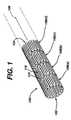
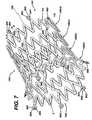
- FIG. 1 and 2a stent 100, which may be utilized in connection with the present invention.
- Figures 1 and 2illustrate the exemplary stent 100 in its unexpanded or compressed state.
- the stent 100is preferably made from a superelastic alloy such as Nitinol.
- the stent 100is made from an alloy comprising from about 50.0 percent (as used herein these percentages refer to weight percentages) Ni to about 60 percent Ni, and more preferably about 55.8 percent Ni, with the remainder of the alloy being Ti.
- the stent 100is designed such that it is superelastic at body temperature, and preferably has an Af in the range from about twenty-four degrees C to about thirty-seven degrees C. The superelastic design of the stent 100 makes it crush recoverable, which, as discussed above, makes it useful as a stent or frame for any number of vascular devices in different applications.
- Stent 100is a tubular member having front and back open ends 102 and 104 and a longitudinal axis 106 extending therebetween.
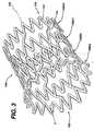
- the tubular memberhas a first smaller diameter, Figures 1 and 2, for insertion into a patient and navigation through the vessels, and a second larger diameter, Figures 3 and 4, for deployment into the target area of a vessel.
- the tubular memberis made from a plurality of adjacent hoops 108, Figure 1 showing hoops 108(a) - 108(d), extending between the front and back ends 102 and 104.
- the hoops 108include a plurality of longitudinal struts 110 and a plurality of loops 112 connecting adjacent struts, wherein adjacent struts are connected at opposite ends so as to form a substantially S or Z shape pattern.
- the loops 112are curved, substantially semi-circular with symmetrical sections about their centers 114.
- Stent 100further includes a plurality of bridges 116 which connect adjacent hoops 108 and which can best be described in detail by referring to Figure 5.
- Each bridge 116has two ends 118 and 120.
- the bridges 116have one end attached to one strut and/or loop, and another end attached to a strut and/or loop on an adjacent hoop.
- the bridges 116connect adjacent struts together at bridge to loop connection points 122 and 124.
- bridge end 118is connected to loop 114(a) at bridge to loop connection point 122
- bridge end 120is connected to loop 114(b) at bridge to loop connection point 124.
- Each bridge to loop connection pointhas a center 126.
- the bridge to loop connection pointsare separated angularly with respect to the longitudinal axis. That is, the connection points are not immediately opposite each other. Essentially, one could not draw a straight line between the connection points, wherein such line would be parallel to the longitudinal axis of the stent.
- the above-described geometryhelps to better distribute strain throughout the stent, prevents metal-to-metal contact when the stent is bent, and minimizes the opening size between the struts, loops and bridges.
- the number of and nature of the design of the struts, loops and bridgesare important factors when determining the working properties and fatigue life properties of the stent. It was previously thought that in order to improve the rigidity of the stent, that struts should be large, and therefore there should be fewer struts per hoop. However, it has now been discovered that stents having smaller struts and more struts per hoop actually improve the construction of the stent and provide greater rigidity.
- each hoophas between twenty-four to thirty-six or more struts. It has been determined that a stent having a ratio of number of struts per hoop to strut length L (in inches) which is greater than four hundred has increased rigidity over prior art stents, which typically have a ratio of under two hundred. The length of a strut is measured in its compressed state parallel to the longitudinal axis 106 of the stent 100 as illustrated in Figure 1.
- the geometry of the stent 100changes quite significantly as the stent 100 is deployed from its un-expanded state to its expanded state.
- the strut angle and strain levels in the loops and bridgesare affected.
- all of the stent featureswill strain in a predictable manner so that the stent is reliable and uniform in strength.
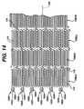
- the stentsits in the delivery system in its un-expanded state as shown in Figures 10 and 11.
- Nitinol stents made from wiredeploy in much the same manner, and are dependent upon the same design constraints, as laser cut stents.
- Stainless steel stentsdeploy similarly in terms of geometric changes as they are assisted by forces from balloons or other devices.
- the present inventionutilizes structural geometries which distribute strain to areas of the stent which are less susceptible to failure than others.
- one of the most vulnerable areas of the stentis the inside radius of the connecting loops.
- the connecting loopsundergo the most deformation of all the stent features.
- the inside radius of the loopwould normally be the area with the highest level of strain on the stent. This area is also critical in that it is usually the smallest radius on the stent.
- Stress concentrationsare generally controlled or minimized by maintaining the largest radii possible.
- One way to accomplish thisis to utilize the largest possible radii while maintaining feature widths which are consistent with applied forces.
- Another considerationis to minimize the maximum open area of the stent. Efficient utilization of the original tube from which the stent is cut increases stent strength and its ability to trap embolic material.
- This featureallows for maximum utilization of Ni-Ti or other material properties to enhance radial strength, to improve stent strength uniformity, to improve fatigue life by minimizing local strain levels, to allow for smaller open areas which enhance entrapment of embolic material, and to improve stent apposition in irregular vessel wall shapes and curves.
- stent 100comprises strut connecting loops 112 having a width W1, as measured at the center 114 parallel to axis 106, which are greater than the strut widths W2, as measured perpendicular to axis 106 itself.
- the thickness of the loopsvary so that they are thickest near their centers. This increases strain deformation at the strut and reduces the maximum strain levels at the extreme radii of the loop. This reduces the risk of stent failure and allows one to maximize radial strength properties. This feature is particularly advantageous for stents having large expansion ratios, which in turn requires them to have extreme bending requirements where large elastic strains are required.
- Nitinolcan withstand extremely large amounts of elastic strain deformation, so the above features are well suited to stents made from this alloy. As stated above, this feature allows for maximum utilization of Ni-Ti or other material properties to enhance radial strength, to improve stent strength uniformity, to improve fatigue life by minimizing local strain levels, to allow for smaller open areas which enhance entrapment of embolic material, and to improve stent apposition in irregular vessel wall shapes and curves.
- bridge geometrychanges as a stent is deployed from its compressed state to its expanded state and vise-versa.
- strut angle and loop strainis affected. Since the bridges are connected to either the loops, struts or both, they are affected. Twisting of one end of the stent with respect to the other, while loaded in the stent delivery system, should be avoided. Local torque delivered to the bridge ends displaces the bridge geometry. If the bridge design is duplicated around the stent perimeter, this displacement causes rotational shifting of the two loops being connected by the bridges. If the bridge design is duplicated throughout the stent, as in the present invention, this shift will occur down the length of the stent.
- a stent delivery systemsuch as the one described below, will deploy the distal end first, then allow the proximal end to expand. It would be undesirable to allow the distal end to anchor into the vessel wall while holding the stent fixed in rotation, then release the proximal end. This could cause the stent to twist or whip in rotation to equilibrium after it is at least partially deployed within the vessel. Such whipping action may cause damage to the vessel.
- one exemplary embodiment of the present inventionreduces the chance of such events happening when deploying the stent.
- the rotational shift of the Z-sections or S-sectionsmay be made to alternate and will minimize large rotational changes between any two points on a given stent during deployment or constraint. That is, the bridges 116 connecting loop 108(b) to loop 108(c) are angled upwardly from left to right, while the bridges connecting loop 108(c) to loop 108(d) are angled downwardly from left to right. This alternating pattern is repeated down the length of the stent 100.
- This alternating pattern of bridge slopesimproves the torsional characteristics of the stent so as to minimize any twisting or rotation of the stent with respect to any two hoops.
- This alternating bridge slopeis particularly beneficial if the stent starts to twist in vivo. As the stent twists, the diameter of the stent will change. Alternating bridge slopes tend to minimize this effect. The diameter of a stent having bridges which are all sloped in the same direction will tend to grow if twisted in one direction and shrink if twisted in the other direction. With alternating bridge slopes this effect is minimized and localized.
- stentsare laser cut from small diameter tubing.
- this manufacturing processled to designs with geometric features, such as struts, loops and bridges, having axial widths W2, W 1 and W3, respectively, which are larger than the tube wall thickness T (illustrated in Figure 3).
- struts, loops and bridgeshaving axial widths W2, W 1 and W3, respectively, which are larger than the tube wall thickness T (illustrated in Figure 3).
- This featureallows for maximum utilization of Ni-Ti or other material properties to enhance radial strength, to improve stent strength uniformity, to improve fatigue life by minimizing local strain levels, to allow for smaller open areas which enhance entrapment of embolic material, and to improve stent apposition in irregular vessel wall shapes and curves.
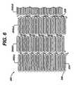
- FIG. 6shows stent 200 which is similar to stent 100 illustrated in Figures 1-5.
- Stent 200is made from a plurality of adjacent hoops 202, Figure 6 showing hoops 202(a) - 202(d).
- the hoops 202include a plurality of longitudinal struts 204 and a plurality of loops 206 connecting adjacent struts, wherein adjacent struts are connected at opposite ends so as to form a substantially S or Z shape pattern.
- Stent 200further includes a plurality of bridges 208 which connect adjacent hoops 202. As seen from the figure, bridges 208 are non-linear and curve between adjacent hoops.
- the stent of the present inventionbe made from a superelastic alloy and most preferably made of an alloy material having greater than 50.5 atomic percentage Nickel and the balance Titanium. Greater than 50.5 atomic percentage Nickel allows for an alloy in which the temperature at which the martensite phase transforms completely to the austenite phase (the Af temperature) is below human body temperature, and preferably is about twenty-four degrees C to about thirty-seven degrees C, so that austenite is the only stable phase at body temperature.
- Nitinol tubingis commercially available from a number of suppliers including Nitinol Devices and Components, Fremont CA.
- the tubular memberis then loaded into a machine which will cut the predetermined pattern of the stent into the tube, as discussed above and as shown in the figures.
- Machines for cutting patterns in tubular devices to make stents or the likeare well known to those of ordinary skill in the art and are commercially available.
- Such machinestypically hold the metal tube between the open ends while a cutting laser, preferably under microprocessor control, cuts the pattern.
- the pattern dimensions and styles, laser positioning requirements, and other informationare programmed into a microprocessor, which controls all aspects of the process.
- the stent patternis cut, the stent is treated and polished using any number of methods or combination of methods well known to those skilled in the art. Lastly, the stent is then cooled until it is completely martensitic, crimped down to its un-expanded diameter and then loaded into the sheath of the delivery apparatus.
- Figure 15illustrates an alternate exemplary embodiment of a self-expanding stent 1500 formed from Nitinol.
- a plurality of split-bridgesare utilized to fill the gap between unbridged loops without serving as a structural connection point between these loops.
- the resulting gaps between unconnected loopsmay be disadvantageous, especially during loading of the stent into a stent delivery system and subsequent deployment from a stent delivery system. In both the loading and deployment situations, the stent is constrained to a small diameter and subjected to high compressive axial forces.
- a split- bridgemay be utilized to substantially minimize this undesirable deformation under conditions of constrained axial compression.
- the wide flat surfaces of adjacent ends of the split-bridgequickly come into contact and transmit compressive axial loads without allowing undesirable deformation of the stent structure.
- the split-bridge designis particularly advantageous in that it allows the transmission of the compressive axial loads during stent loading and deployment without the loss of flexibility caused by standard bridges once the stent is deployed.
- a simple examplemay be utilized to illustrate the usefulness of a stent comprising split-bridges.
- a constrained stentwhich comprises three bridges, typically spaced one hundred twenty degrees apart, must transmit the entire compressive load associated with stent loading and deployment through these three bridges. Unconnected loops within the one hundred twenty degree arc or span between bridges may be undesirably deformed, potentially out of plane, thereby allowing compression of the entire stent structure and potentially adversely impacting loading or deployment characteristics.
- a stent with three standard bridges and three split-bridgeswould better distribute the axial compressive load, with half the load at or on each bridge, now spaced apart by sixty degrees.
- the split-bridgehelps to prevent undesirable compression or deformation of the constrained stent and loading or deployment difficulties, which may result from such compression or deformation. This may facilitate loading and delivery of stent designs which might otherwise be impractical.
- the split-bridge designmay be utilized in any number of stent designs, for ease of explanation, the split-bridge design is described with respect to the exemplary stent illustrated in Figure 15.
- the stent 1500comprises a plurality of adjacent hoops 1502.
- the hoops 1502include a plurality of longitudinal struts 1504 and a plurality of loops 1506 connecting adjacent struts 1504, wherein adjacent struts 1504 are connected at opposite ends so as to form a substantially S or Z shape pattern.
- the loops 1506are curved, substantially semi-circular with symmetrical sections about their centers 1508.
- the stent 1500further comprises a plurality of bridges 1510 which connect adjacent hoops 1502.
- the bridges 1510are equivalent to the bridges illustrated in Figure 5 and described above.
- the bridge orientationis changed from hoop to hoop so as to minimize rotational changes between any two points on a given stent during stent deployment or constraint.
- the number of and nature of the design of the struts, loops and bridgesare important factors when determining the working properties and fatigue life properties of the stent as is discussed above.
- the stent 1500also comprises a plurality of split-bridges 1512.
- the split-bridges 1512may comprise any suitable configuration and may be positioned in any suitable pattern between bridges 1510.
- the split-bridges 1512are orientated in a direction opposite from that of the bridges 1510 such that a symmetric configuration of bridges 1510 and split-bridges 1512 results.
- a symmetric configurationis not required, but it is preferred.
- the split-bridges 1512is designed to maximize the surface area for contact between adjacent sections of the split-bridges 1512. This split-bridge design allows for contact between adjacent sections and thus force transmission even if the adjacent hoops 1502 become somewhat misaligned.
- the width or thickness of the split-bridges 1512is preferably larger than the width or thickness of the standard bridges 1510 to provide additional surface area for abutting contact.
- the split-bridges 1512have one end of one independent section attached to the one loop 1506 and another end of one independent section attached to a loop 1506 on an adjacent hoop 1502.
- each split-bridge 1512comprises first and second independent sections which come into contact when the stent 1500 is under compressive axial loading and make no contact when the stent 1500 is deployed.
- the geometry of the split-bridgemay take any number of forms which serves the purpose of filling the gaps which may be unoccupied by standard bridges. In addition, the number and arrangement of split-bridges is virtually unlimited.
- the split-bridgeadvantageously allows transmission of compressive loads when constrained because the sections of each split-bridge abut at least partially. However, unlike a traditional bridge, it does not transmit tensile or compressive strains when the expanded structure is stretched, compressed or bent. As illustrated in Figure 16, the split-bridges are not aligned once the structure is expanded. As such, the split-bridge may prove advantageous over a traditional bridge in contourability and fatigue durability.
- stentsVarious drugs, agents or compounds may be locally delivered via medical devices such as stents.
- rapamycin and/or heparinmay be delivered by a stent to reduce restenosis, inflammation and coagulation.
- One potential limiting factor in these stentsis the surface area available on the stent for the drugs, agents and/or compounds. Accordingly, in addition to the advantages discussed above, the split-bridge offers additional surface area onto which various drugs, agents and/or compounds may be affixed.
- markers having a radiopacity greater than that of the superelastic alloysmay be utilized to facilitate more precise placement of the stent within the vasculature.
- markersmay be utilized to determine when and if a stent is fully deployed. For example, by determining the spacing between the markers, one can determine if the deployed stent has achieved its maximum diameter and adjusted accordingly utilizing a tacking process.
- Figure 7illustrates an exemplary embodiment of the stent 100 illustrated in Figures 1-5 having at least one marker on each end thereof.
- a stent having thirty-six struts per hoopcan accommodate six markers 800.
- Each marker 800comprises a marker housing 802 and a marker insert 804.
- the marker insert 804may be formed from any suitable biocompatible material having a high radiopacity under X-ray fluoroscopy. In other words, the marker inserts 804 should preferably have a radiopacity higher than that of the material comprising the stent 100.
- the addition of the marker housings 802 to the stentnecessitates that the lengths of the struts in the last two hoops at each end of the stent 100 be longer than the strut lengths in the body of the stent to increase the fatigue life at the stent ends.
- the marker housings 802are preferably cut from the same tube as the stent as briefly described above. Accordingly, the housings 802 are integral to the stent 100. Having the housings 802 integral to the stent 100 serves to ensure that the markers 800 do not interfere with the operation of the stent
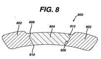
- Figure 8is a cross-sectional view of a marker housing 802.
- the housing 802may be elliptical when observed from the outer surface as illustrated in Figure 7.
- the hole 806 in the marker housing 802is conical in the radial direction with the outer surface 808 having a diameter larger than the diameter of the inner surface 810, as illustrated in Figure 8.
- the conical tapering in the marker housing 802is beneficial in providing an interference fit between the marker insert 804 and the marker housing 802 to prevent the marker insert 804 from being dislodged once the stent 100 is deployed. A detailed description of the process of locking the marker insert 804 into the marker housing 802 is given below.
- the marker inserts 804may be made from any suitable material having a radiopacity higher than the superelastic material forming the stent or other medical device.
- the marker insert 804may be formed from niobium, tungsten, gold, platinum or tantalum.
- tantalumis utilized because of its closeness to nickel-titanium in the galvanic series and thus would minimize galvanic corrosion.
- the surface area ratio of the tantalum marker inserts 804 to the nickel-titaniumis optimized to provide the largest possible tantalum marker insert, easy to see, while minimizing the galvanic corrosion potential.
- marker inserts 804having a diameter of 0.254 mm (0.010 inches) could be placed at the end of the stent 100; however, these marker inserts 804 would be less visible under X-ray fluoroscopy.
- three to four marker inserts 804 having a diameter of 0.635 mm (0.025 inches)could be accommodated on the stent 100; however, galvanic corrosion resistance would be compromised.
- six tantalum markers having a diameter of 0.508 mm (0.020 inches)are utilized on each end of the stent 100 for a total of twelve markers 800.
- the tantalum markers 804may be manufactured and loaded into the housing utilizing a variety of known techniques.
- the tantalum markers 804are punched out from an annealed ribbon stock and are shaped to have the same curvature as the radius of the marker housing 802 as illustrated in Figure 8.
- a coining processis used to properly seat the marker insert 804 below the surface of the housing 802.
- the coining punchis also shaped to maintain the same radius of curvature as the marker housing 802. As illustrated in Figure 8, the coining process deforms the marker housing 802 material to lock in the marker insert 804.
- the hole 806 in the marker housing 802is conical in the radial direction with the outer surface 808 having a diameter larger than the diameter of the inner surface 810 as illustrated in Figure 8.
- the inside and outside diametersvary depending on the radius of the tube from which the stent is cut.
- the marker inserts 804, as stated above,are formed by punching a tantalum disk from annealed ribbon stock and shaping it to have the same radius of curvature as the marker housing 802. It is important to note that the marker inserts 804, prior to positioning in the marker housing 804, have straight edges. In other words, they are not angled to match the hole 806.
- the diameter of the marker insert 804is between the inside and outside diameter of the marker housing 802.
- the thickness of the marker insert 804is less than or equal to the thickness of the tubing and thus the thickness or height of the hole 806. Accordingly, by applying the proper pressure during the coining process and using a coining tool that is larger than the marker insert 804, the marker insert 804 may be seated in the marker housing 802 in such a way that it is locked into position by a radially oriented protrusion 812. Essentially, the applied pressure, and size and shape of the housing tool forces the marker insert 804 to form the protrusion 812 in the marker housing 802.
- the coining toolis also shaped to maintain the same radius of curvature as the marker housing 802. As illustrated in Figure 8, the protrusion 812 prevents the marker insert 804 from becoming dislodged from the marker housing 802.
- the marker inserts 804are positioned in and locked into the marker housing 802 when the stent 100 is in its unexpanded state. This is due to the fact that it is desirable that the tube's natural curvature be utilized. If the stent were in its expanded state, the coining process would change the curvature due to the pressure or force exerted by the coining tool.
- the marker inserts 804form a substantially solid line that clearly defines the ends of the stent in the stent delivery system when seen under fluoroscopic equipment.
- the markers 800move away from each other and flower open as the stent 100 expands as illustrated in Figure 7.
- the change in the marker groupingprovides the physician or other health care provider with the ability to determine when the stent 100 has been fully deployed from the stent delivery system.
- markers 800may be positioned at other locations on the stent 100.
- FIG 13illustrates an alternate exemplary embodiment of a radiopaque marker 900.
- the marker housing 902comprises flat sides 914 and 916.
- the flat sides 914 and 916serve a number of functions. Firstly, the flat sides 914 and 916 minimize the overall profile of the stent 100 without reducing the radiopacity of the stent 100 under x-ray fluoroscopy. Essentially, the flat sides 914 and 916 allow the marker housings 902 to fit more closely together when the stent 100 is crimped for delivery. Accordingly, the flat sides 914 and 916 of the marker housing 902 allow for larger stents to utilize high radiopacity markers while also allowing the stent to fit into smaller delivery systems.
- the flat sides 914 and 916 on radiopaque markers 900 of the size described aboveallow a stent to maintain a radiopaque stent marker size utilized in a seven French delivery system to fit into a six French delivery system.
- the flat sides 914 and 916also maximize the nitinol tab to radiopaque marker material ratio, thereby further reducing the effects of any galvanic corrosion as described above.
- the marker insert 904 and the marker hole 906are formed of the same materials and have the same shape as described above with respect to Figures 1-12.
- the markers 900are also constructed utilizing the same coining process as described above.
- FIG 14illustrates yet another alternate exemplary embodiment of a radiopaque marker 1000.
- This exemplary embodimentoffers the same advantages as the above-described embodiment; namely, reduced profile without reduction in radiopacity and a reduction in the effects of galvanic corrosion.
- the radiopaque marker 1000has substantially the same total area as that of the markers 900, 800 described above, but with an oval shape rather than a circular shape or circular shape with flat sides.
- the marker 1000comprises a substantially oval shaped marker housing 1002 and a substantially oval shaped marker insert 1004.
- the marker 1000is longer in the axial direction and shorter in the radial direction to allow a larger stent to fit into a smaller delivery system as described above.
- the nitinol tab to radiopaque marker material ratiois improved.
- the substantially oval shapeprovides for a more constant marker housing 1002 thickness around the marker insert 1004.
- markers described hereinmay be utilized or any of the stent designs illustrated as well as any other stent requiring improved radiopacity.
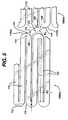
- FIG. 10 and 11show a self-expanding stent delivery apparatus 10 for a stent made in accordance with the present invention.
- Apparatus 10comprises inner and outer coaxial tubes.
- the inner tubeis called the shaft 12 and the outer tube is called the sheath 14.
- Shaft 12has proximal and distal ends. The proximal end of the shaft 12 terminates at a luer lock hub 16.
- shaft 12has a proximal portion 18 which is made from a relatively stiff material such as stainless steel, Nitinol, or any other suitable material, and a distal portion 20 which may be made from a polyethylene, polyimide, Pellethane, Pebax, Vestamid, Cristamid, Grillamid or any other suitable material known to those of ordinary skill in the art.
- the two portionsare joined together by any number of means known to those of ordinary skill in the art.
- the stainless steel proximal endgives the shaft the necessary rigidity or stiffness it needs to effectively push out the stent, while the polymeric distal portion provides the necessary flexibility to navigate tortuous vessels.
- the distal portion 20 of the shaft 12has a distal tip 22 attached thereto.
- the distal tip 22has a proximal end 24 whose diameter is substantially the same as the outer diameter of the sheath 14.
- the distal tip 22tapers to a smaller diameter from its proximal end to its distal end, wherein the distal end 26 of the distal tip 22 has a diameter smaller than the inner diameter of the sheath 14.
- a stop 28which is proximal to the distal tip 22. Stop 28 may be made from any number of materials known in the art, including stainless steel, and is even more preferably made from a highly radiopaque material such as platinum, gold or tantalum.
- stop 28is substantially the same as the inner diameter of sheath 14, and would actually make frictional contact with the inner surface of the sheath. Stop 28 helps to push the stent out of the sheath during deployment, and helps keep the stent from migrating proximally into the sheath 14.
- a stent bed 30is defined as being that portion of the shaft between the distal tip 22 and the stop 28.
- the stent bed 30 and the stent 100are coaxial so that the distal portion 20 of shaft 12 comprising the stent bed 30 is located within the lumen of the stent 100.
- the stent bed 30does not make any contact with stent 100 itself.
- shaft 12has a guidewire lumen 32 extending along its length from its proximal end and exiting through its distal tip 22. This allows the shaft 12 to receive a guidewire much in the same way that an ordinary balloon angioplasty catheter receives a guidewire.
- Such guidewiresare well known in art and help guide catheters and other medical devices through the vasculature of the body.
- Sheath 14is preferably a polymeric catheter and has a proximal end terminating at a sheath hub 40. Sheath 14 also has a distal end which terminates at the proximal end 24 of distal tip 22 of the shaft 12, when the stent is in its fully un-deployed position as shown in the figures.
- the distal end of sheath 14includes a radiopaque marker band 34 disposed along its outer surface. As will be explained below, the stent is fully deployed from the delivery apparatus when the marker band 34 is lined up with radiopaque stop 28, thus indicating to the physician that it is now safe to remove the apparatus 10 from the body.
- Sheath 14preferably comprises an outer polymeric layer and an inner polymeric layer.
- Braided reinforcing layerPositioned between outer and inner layers is a braided reinforcing layer. Braided reinforcing layer is preferably made from stainless steel. The use of braided reinforcing layers in other types of medical devices can be found in US-3,585,707 (Stevens) issued on June 22, 1971, US-5,045,072 (Castillo et al.) issued on September 3, 1991, and US-5,254,107 (Soltesz) on October 19, 1993.
- FIGS 10 and 11illustrate the stent 100 as being in its fully un-deployed position. This is the position the stent is in when the apparatus 10 is inserted into the vasculature and its distal end is navigated to a target site.
- Stent 100is disposed around stent bed 30 and at the distal end of sheath 14.
- the distal tip 22 of the shaft 12is distal to the distal end of the sheath 14, and the proximal end of the shaft 12 is proximal to the proximal end of the sheath 14.
- the stent 100is in a compressed state and makes frictional contact with the inner surface 36 of the sheath 14.
- a Tuohy Borst valve 38When being inserted into a patient, sheath 14 and shaft 12 are locked together at their proximal ends by a Tuohy Borst valve 38. This prevents any sliding movement between the shaft and sheath which could result in a premature deployment or partial deployment of the stent 100. When the stent 100 reaches its target site and is ready for deployment, the Tuohy Borst valve 38 is opened so that that the sheath 14 and shaft 12 are no longer locked together.
- the method under which the apparatus 10 deploys the stent 100is readily apparent.
- the apparatus 10is first inserted into the vessel until the radiopaque stent markers 800 (leading 102 and trailing 104 ends, see Figure 7) are proximal and distal to the target lesion. Once this has occurred the physician would open the Tuohy Borst valve 38. The physician would then grasp hub 16 of shaft 12 so as to hold it in place. Thereafter, the physician would grasp the proximal end of the sheath 14 and slide it proximal, relative to the shaft 12. Stop 28 prevents the stent 100 from sliding back with the sheath 14, so that as the sheath 14 is moved back, the stent 100 is pushed out of the distal end of the sheath 14.
- the radiopaque stent markers 800move apart once they come out of the distal end of sheath 14. Stent deployment is complete when the marker 34 on the outer sheath 14 passes the stop 28 on the inner shaft 12. The apparatus 10 can now be withdrawn through the stent 100 and removed from the patient.
- Figure 12illustrates the stent 100 in a partially deployed state. As illustrated, as the stent 100 expands from the delivery device 10, the markers 800 move apart from one another and expand in a flower like manner.
- FIG 17illustrates yet another alternate exemplary embodiment of a self-expanding stent 1700 formed from Nitinol.
- a plurality of anvil bridgesare utilized to fill the gap between unbridged loops without serving as a structural connection point between these loops.
- the split-bridge embodiment described abovecomprises a pair of structural elements originating from adjacent loops on adjacent hoops. These pairs of structural elements come into contact when the stent is placed in axial compression, thereby providing a means for transmitting axial loading without undesirable deformation of the stent structure or closing of the gaps between hoops and resulting compression of the constrained structure.
- the anvil bridge embodimentcomprises only a single element which originates from one loop and comes into mating or abutting contact with a flattened area of at least one adjacent loop on an adjacent hoop when under axial compression.
- the anvil bridge stent 1700comprises a plurality of adjacent hoops 1702.
- the hoops 1702include a plurality of longitudinal struts 1704 and a plurality of loops 1706 connecting adjacent struts 1704, wherein adjacent struts 1704 are connected at opposite ends so as to form a substantially S or Z shape pattern.
- the loops 1706are curved, substantially semi-circular with symmetrical sections about their centers 1708.
- the stent 1700further comprises a plurality of bridges 1710 which connect adjacent hoops 1702.
- the bridges 1710are equivalent to the bridges illustrated in Figures 5 and 15 and described above; however, the bridges 1710 may assume a variety of alternate configurations.
- the bridge orientationis changed from hoop to hoop so as to minimize rotational changes between any two points on a given stent during constraint or deployment.
- the number of and nature of the design of the struts 1704, loops 1706 and bridges 1710are important factors when determining the working properties and fatigue life properties of the stent as is discussed in detail above.
- the stent 1700also comprises a plurality of anvil bridges 1712.
- the anvil bridges 1712may comprise any suitable configuration and may be positioned in any suitable pattern between bridges 1710. As set forth above, symmetric loading and hence symmetric placement of the bridges, both regular and anvil type, is preferable but not necessary. In the exemplary embodiment illustrated in Figure 17, the anvil bridges 1712 are centered between bridges 1710 such that a symmetric configuration of bridges 1710 and anvil bridges 1712 results.
- the anvil bridge 1712comprises a one-piece structure which extends from one loop 1706 on one hoop 1702 to a flat surface 1714 formed in two loops 1706 on an adjacent hoop 1702 when the stent is under axial compressive loading.
- the flat surface 1714is preferable, but not necessary.
- the anvil bridge one-piece structure 1712extends from a single loop 1706 and has an increasing profile until it forms a flat anvil-like surface.
- the anvil designprovides more contact surface area then other designs. This allows the design to be more tolerant of misalignments resulting from variation in constraint diameter and loading deformation.
- the contact surface area on the adjacent hoop 1702requires the flat surface 1714 be formed from two longitudinally adjacent loops 1706.
- the flat surface 1714is preferable, but not required.
- the contact surface areamay comprise one loop, two loops as described, or more than 2 loops.
- the anvil bridgeitself is designed to maximize contact surface area and the mating surfaces of the adjacent tips are flattened for the same reason.
- the mating contact surfaces 1714include two loops 1706. All of these factors allow for loading forces to be distributed over a larger area. This allows for more uniform distribution of loading forces throughout the structure, improving stability and decreasing the likelihood of undesirable deformation when the constrained structure is loaded in axial compression.
- the geometry of the anvil bridgemay take any number of forms which serves the purpose of filling the gaps which may be unoccupied by standard bridges.
- the number and arrangement of axial bridgesis virtually unlimited.
- the arrangement of the markers 800, standard bridges 1710 and anvil bridges 1712was carefully chosen to promote purely axial load transmission through the stent 1700 structure.
- the anvil bridgeadvantageously allows transmission of compressive loads when constrained because the anvil portion abuts or makes at least partial contact with the contact surface 1714.
- itdoes not transmit tensile or compressive strains when the expanded structure is stretched, compressed or bent.
- the anvil bridges 1712are not aligned once the stent 1700 is expanded. As such, the anvil bridge may provide advantages over a traditional bridge in contourability and fatigue durability.
- various drugs, agents or compoundsmay be locally delivered via medical devices such as stents.
- rapamycin and/or heparinmay be delivered by a stent to reduce restenosis, inflammation and coagulation.
- the additional stent surface area provided by the anvil bridgeswould be beneficial if an additional amount of the drug, agent, and/or compound is required for a specific dosing, release profile or the like.
- Conventional vascular stentsgenerally comprise a series of ring-like radially expandable structural members which are axially connected by bridging elements as described herein.
- a stentWhen a stent is subjected to in vivo bending, stretching or compression, its constituent ring-like members distribute themselves accordingly, thereby allowing the stent structure to conform to its vascular surroundings.
- These loading conditions on the stent structurecause adjacent ring-like structural members (hoops) to change their relative axial position.
- the ring-like structural memberswill tend to pull apart from each other or squeeze more closely together depending on local loading conditions.
- the bridging elementsact to constrain adjacent, ring-like members, providing a geometrical structural connection between these members. As such, these bridging elements communicate strain between the adjacent ring-like members.
- a stentmay be constructed from a plurality of individual stent segments which are coupled prior to deployment and which are uncoupled upon deployment.
- the vascular scaffolding or stent structurecomprises individual, independent, self-expanding stent segments, which are designed to interlock when constrained within a stent delivery sheath and uncouple upon deployment as the delivery sheath is retracted.
- This alternate exemplary stent designprovides a means for reducing or eliminating bridging elements, thereby allowing adjacent ring-like structural members independence from each other.
- This exemplary designprovides for a series of axially independent ring-like members which comprise a composite stent structure. With such a construction, adjacent ring-like members could move relative to one another without inducing strain in the overall structure. As such, the composite stent structure could experience cyclic axial compression or extension, bending, or twisting without experiencing cyclic strain relating to these modes of deformation.
- FIG 19illustrates an exemplary embodiment of a self-expanding, composite stent structure 1900 formed from a superelastic alloy such as nitinol. It is important to note, however, that the stent may be constructed from any number of suitable materials.
- each stent segment 1902 of the stent structurecomprises a hoop 1904 formed from a plurality of longitudinal struts 1906 and a plurality of loops 1908 connecting adjacent longitudinal struts 1906, wherein adjacent longitudinal struts 1906 are connected at opposite ends so as to form a substantially "S" or "Z” shape patterns.
- the individual stent segments 1902are constructed as simple "S" or "Z” shaped structures; however, in alternate exemplary embodiments, the individual segments 1902 may comprise any number of design variations, including short segments of conventional stents or similar hybrid designs.
- Each individual stent segment 1902comprises a number of bridging elements 1910 and a number of receptacles 1912.
- the bridging elements 1910are designed to mate with and engage the receptacles 1912 on adjacent stent segments 1902.
- the bridging elements 1910protrude from a predetermined number of loops 1908 on each stent segment 1902.
- the number of bridging elements 1910depends on a number of factors including the radial size or diameter of the stent 1900.
- the receptacles 1912are formed by creating additional space between adjacent longitudinal struts 1906 and expanding certain loops 1908.
- Each bridging element 1910includes a protrusion 1914 that fits within a cavity 1916 of each receptacle 1912 when the individual stent segments 1902 are properly nested together and restrained.
- the delivery system for this exemplary stentis designed such that the bridging elements 1910 of the most proximal stent segment 1902 mate with a collar having cavities similar to the cavities 1916 in the receptacles 1912 as described in more detail subsequently.
- the protrusions 1914 and the corresponding cavities 1916have a substantially oval shape. However, in alternate exemplary embodiments, any shape may be utilized.
- the stent segments 1902are not nested. In other words, the longitudinal struts 1906 of one stent segment 1902 does not fit within the longitudinal struts 1906 of an adjacent stent segment 1902. However, by shortening the bridging element 1910, or some other suitable arrangement the stent segments 1902 may be nested. Basically, shortening the bridging elements 1910 allows for nesting of the stent segments 1902, and nested segments allow for better coverage. However, longer bridging elements 1910 allow for better deployment stability.
- Figure 20illustrates the deployment of the individual stent segments 1902 which uncouple as the sheath 2000 is retracted.
- the individual stent segments 1902begin to exit the delivery system and expand to their full diameter.
- a segment 1902 exits the sheath 2000it remains coupled to its proximally adjacent segment 1902, as illustrated at 2002.
- the sheath 2000is further retracted and the stent segment 1902 achieves opposition to the vessel wall, as illustrated at 2004, the next stent segment 1902 begins to deploy from the sheath 2000, thus releasing the bridging element 1910.
- the individual stent segments 1902are fully independent from adjacent segments.
- the bridging elements 1910remain, but are no longer coupled.
- a significant advantage of this exemplary stentis the ability to deploy individual stent segments in a controlled fashion.
- the interlocking couplingmay be designed such that it does not disengage a deployed segment from the delivery system until it is firmly opposed to the vessel wall. Without such a mechanism, short individual segments could potentially propel themselves out of the delivery system in an uncontrolled fashion as they expand to their full diameter.
- Figure 21illustrates and exemplary delivery device in accordance with the present invention.
- the exemplary delivery deviceis substantially identical to the delivery device described herein and illustrated in Figures 10 and 11.
- the shaft 12may comprise a collar or a modified stop 28.
- the modified stop/collar 28comprises mating openings 29 that correspond in shape to the cavities 1916 of the stent segments 1902 ( Figure 19).
- the number of mating openings 29depends on the number of bridging elements 1910 ( Figure 19).
- the delivery devicemay be utilized to deploy a given number of stent segments thereby allowing the physician to treat various size lesions and/or multiple lesions.
- the radiopaque markers disclosed hereinmay be incorporated into the design of the individual stent segments.
- the markers illustrated in Figures 7, 8 and 9may be incorporated into the bridging elements 1910.
- a marker housing and marker insertmay be utilized. Accordingly, the markers would serve a dual purpose.
- the end segmentsmay comprise the markers as described above.
Landscapes
- Health & Medical Sciences (AREA)
- Engineering & Computer Science (AREA)
- Biomedical Technology (AREA)
- Cardiology (AREA)
- Oral & Maxillofacial Surgery (AREA)
- Transplantation (AREA)
- Heart & Thoracic Surgery (AREA)
- Vascular Medicine (AREA)
- Life Sciences & Earth Sciences (AREA)
- Animal Behavior & Ethology (AREA)
- General Health & Medical Sciences (AREA)
- Public Health (AREA)
- Veterinary Medicine (AREA)
- Physics & Mathematics (AREA)
- Optics & Photonics (AREA)
- Media Introduction/Drainage Providing Device (AREA)
- Prostheses (AREA)
- Materials For Medical Uses (AREA)
Abstract
Description
Claims (10)
- An intraluminal medical device comprising multiple, independent, self-expandingstent segments, each stent segment including a plurality of longitudinal struts, a plurality ofloops connecting adjacent struts, at least one bridging element and at least one receptacle,wherein the at least one bridging element of one or more of the stent segments isconfigured to be releasably engaged with the at least one receptacle on an adjacent stentsegment.
- The intraluminal medical device according to Claim 1, wherein the at least onebridging element comprises an elongate member extending from one of the plurality ofloops and having a free end with a mating protrusion.
- The intraluminal medical device according to Claim 2, wherein the at least onereceptacle is configured as a space between adjacent longitudinal struts and defines a cavityfor the elongate member and mating protrusion.
- The intraluminal medical device according to Claim 3, wherein the cavity and themating protrusion have a substantially oval shape.
- The intraluminal medical device according to Claim 4, wherein the self-expandingstent segments comprise a superelastic alloy.
- The intraluminal medical device according to Claim 5, wherein the superelasticalloy comprises from about fifty percent to about sixty percent Nickel and the remaindertitanium.
- The intraluminal medical device according to Claim 1, wherein the plurality ofstruts and the plurality of loops form a substantially S-shaped configuration.
- The intraluminal medical device according to Claim 1, further comprising one ormore radiopaque markers.
- The intraluminal medical device according to Claim 8, wherein the one or moremarkers are incorporated into the mating protrusion.
- A delivery system for a segmented, self-expanding stent comprising:an outer sheath including an elongated tubular member having distal and proximalends; andan inner shaft located coaxially and slidably within the outer sheath, the innershaft having a distal end and a proximal end, the shaft having a collar including matingsections for releasably securing at least a portion of the segmented, self-expanding stent.
Applications Claiming Priority (2)
| Application Number | Priority Date | Filing Date | Title |
|---|---|---|---|
| US687143 | 2003-10-16 | ||
| US10/687,143US7175654B2 (en) | 2003-10-16 | 2003-10-16 | Stent design having stent segments which uncouple upon deployment |
Publications (3)
| Publication Number | Publication Date |
|---|---|
| EP1523960A2true EP1523960A2 (en) | 2005-04-20 |
| EP1523960A3 EP1523960A3 (en) | 2005-06-29 |
| EP1523960B1 EP1523960B1 (en) | 2008-12-10 |
Family
ID=34377654
Family Applications (1)
| Application Number | Title | Priority Date | Filing Date |
|---|---|---|---|
| EP04256319AExpired - LifetimeEP1523960B1 (en) | 2003-10-16 | 2004-10-14 | Stent design having stent segments which uncouple upon deployment |
Country Status (6)
| Country | Link |
|---|---|
| US (1) | US7175654B2 (en) |
| EP (1) | EP1523960B1 (en) |
| JP (1) | JP2005118571A (en) |
| AT (1) | ATE416721T1 (en) |
| CA (1) | CA2484828C (en) |
| DE (1) | DE602004018245D1 (en) |
Cited By (39)
| Publication number | Priority date | Publication date | Assignee | Title |
|---|---|---|---|---|
| US7402168B2 (en) | 2005-04-11 | 2008-07-22 | Xtent, Inc. | Custom-length stent delivery system with independently operable expansion elements |
| DE102007030753A1 (en)* | 2007-07-02 | 2009-01-08 | Acandis Gmbh & Co. Kg | stent |
| US7553324B2 (en) | 2003-10-14 | 2009-06-30 | Xtent, Inc. | Fixed stent delivery devices and methods |
| GB2469296A (en)* | 2009-04-07 | 2010-10-13 | Cook Inc | Modular stent assembly |
| US7892273B2 (en) | 2001-12-03 | 2011-02-22 | Xtent, Inc. | Custom length stent apparatus |
| US7892274B2 (en) | 2001-12-03 | 2011-02-22 | Xtent, Inc. | Apparatus and methods for deployment of vascular prostheses |
| US7918881B2 (en) | 2003-06-09 | 2011-04-05 | Xtent, Inc. | Stent deployment systems and methods |
| WO2011053693A1 (en)* | 2009-10-30 | 2011-05-05 | Cordis Corporation | Intraluminal device with improved flexibility and durability |
| US7938852B2 (en) | 2001-12-03 | 2011-05-10 | Xtent, Inc. | Apparatus and methods for delivery of braided prostheses |
| US8016870B2 (en) | 2001-12-03 | 2011-09-13 | Xtent, Inc. | Apparatus and methods for delivery of variable length stents |
| US8016871B2 (en) | 2001-12-03 | 2011-09-13 | Xtent, Inc. | Apparatus and methods for delivery of multiple distributed stents |
| US8080048B2 (en) | 2001-12-03 | 2011-12-20 | Xtent, Inc. | Stent delivery for bifurcated vessels |
| US8177831B2 (en) | 2001-12-03 | 2012-05-15 | Xtent, Inc. | Stent delivery apparatus and method |
| US8257427B2 (en) | 2001-09-11 | 2012-09-04 | J.W. Medical Systems, Ltd. | Expandable stent |
| US8282680B2 (en) | 2003-01-17 | 2012-10-09 | J. W. Medical Systems Ltd. | Multiple independent nested stent structures and methods for their preparation and deployment |
| US8317859B2 (en) | 2004-06-28 | 2012-11-27 | J.W. Medical Systems Ltd. | Devices and methods for controlling expandable prostheses during deployment |
| US8460358B2 (en) | 2004-03-30 | 2013-06-11 | J.W. Medical Systems, Ltd. | Rapid exchange interventional devices and methods |
| US8486132B2 (en) | 2007-03-22 | 2013-07-16 | J.W. Medical Systems Ltd. | Devices and methods for controlling expandable prostheses during deployment |
| US8585747B2 (en) | 2003-12-23 | 2013-11-19 | J.W. Medical Systems Ltd. | Devices and methods for controlling and indicating the length of an interventional element |
| US8652198B2 (en) | 2006-03-20 | 2014-02-18 | J.W. Medical Systems Ltd. | Apparatus and methods for deployment of linked prosthetic segments |
| US8702781B2 (en) | 2001-12-03 | 2014-04-22 | J.W. Medical Systems Ltd. | Apparatus and methods for delivery of multiple distributed stents |
| US8769796B2 (en) | 2008-09-25 | 2014-07-08 | Advanced Bifurcation Systems, Inc. | Selective stent crimping |
| US8795347B2 (en) | 2008-09-25 | 2014-08-05 | Advanced Bifurcation Systems, Inc. | Methods and systems for treating a bifurcation with provisional side branch stenting |
| US8808347B2 (en) | 2008-09-25 | 2014-08-19 | Advanced Bifurcation Systems, Inc. | Stent alignment during treatment of a bifurcation |
| US8821562B2 (en) | 2008-09-25 | 2014-09-02 | Advanced Bifurcation Systems, Inc. | Partially crimped stent |
| US8979917B2 (en) | 2008-09-25 | 2015-03-17 | Advanced Bifurcation Systems, Inc. | System and methods for treating a bifurcation |
| US8980297B2 (en) | 2007-02-20 | 2015-03-17 | J.W. Medical Systems Ltd. | Thermo-mechanically controlled implants and methods of use |
| US8986362B2 (en) | 2004-06-28 | 2015-03-24 | J.W. Medical Systems Ltd. | Devices and methods for controlling expandable prostheses during deployment |
| US9101503B2 (en) | 2008-03-06 | 2015-08-11 | J.W. Medical Systems Ltd. | Apparatus having variable strut length and methods of use |
| US9254210B2 (en) | 2011-02-08 | 2016-02-09 | Advanced Bifurcation Systems, Inc. | Multi-stent and multi-balloon apparatus for treating bifurcations and methods of use |
| RU2574992C2 (en)* | 2009-10-30 | 2016-02-10 | Кордис Корпорейшн | Intraluminal device with improved flexibility and wear resistance |
| US9364356B2 (en) | 2011-02-08 | 2016-06-14 | Advanced Bifurcation System, Inc. | System and methods for treating a bifurcation with a fully crimped stent |
| WO2017066201A1 (en)* | 2015-10-16 | 2017-04-20 | Abbott Cardiovascular Systems Inc. | Non-circular radiopaque markers and methods for attaching a marker to a scaffold |
| CN107072799A (en)* | 2014-09-04 | 2017-08-18 | 波士顿科学国际有限公司 | The skeleton pattern of bioerodable polymer support |
| US9737424B2 (en) | 2008-09-25 | 2017-08-22 | Advanced Bifurcation Systems, Inc. | Partially crimped stent |
| US10610387B2 (en) | 2015-06-12 | 2020-04-07 | Abbott Cardiovascular Systems Inc. | Scaffolds having a radiopaque marker and methods for attaching a marker to a scaffold |
| US11298252B2 (en) | 2008-09-25 | 2022-04-12 | Advanced Bifurcation Systems Inc. | Stent alignment during treatment of a bifurcation |
| US12076258B2 (en) | 2008-09-25 | 2024-09-03 | Advanced Bifurcation Systems Inc. | Selective stent crimping |
| US12324756B2 (en) | 2008-09-25 | 2025-06-10 | Advanced Bifurcation Systems Inc. | System and methods for treating a bifurcation |
Families Citing this family (137)
| Publication number | Priority date | Publication date | Assignee | Title |
|---|---|---|---|---|
| GB0020491D0 (en) | 2000-08-18 | 2000-10-11 | Angiomed Ag | Stent with attached element and method of making such a stent |
| EP1309289A2 (en) | 2000-08-18 | 2003-05-14 | Atritech, Inc. | Expandable implant devices for filtering blood flow from atrial appendages |
| US7842083B2 (en) | 2001-08-20 | 2010-11-30 | Innovational Holdings, Llc. | Expandable medical device with improved spatial distribution |
| US7182779B2 (en)* | 2001-12-03 | 2007-02-27 | Xtent, Inc. | Apparatus and methods for positioning prostheses for deployment from a catheter |
| US20050085897A1 (en)* | 2003-10-17 | 2005-04-21 | Craig Bonsignore | Stent design having independent stent segments which uncouple upon deployment |
| US7445631B2 (en)* | 2003-12-23 | 2008-11-04 | Sadra Medical, Inc. | Methods and apparatus for endovascularly replacing a patient's heart valve |
| US9526609B2 (en) | 2003-12-23 | 2016-12-27 | Boston Scientific Scimed, Inc. | Methods and apparatus for endovascularly replacing a patient's heart valve |
| US7381219B2 (en) | 2003-12-23 | 2008-06-03 | Sadra Medical, Inc. | Low profile heart valve and delivery system |
| US8579962B2 (en)* | 2003-12-23 | 2013-11-12 | Sadra Medical, Inc. | Methods and apparatus for performing valvuloplasty |
| US20070156225A1 (en)* | 2003-12-23 | 2007-07-05 | Xtent, Inc. | Automated control mechanisms and methods for custom length stent apparatus |
| US7329279B2 (en)* | 2003-12-23 | 2008-02-12 | Sadra Medical, Inc. | Methods and apparatus for endovascularly replacing a patient's heart valve |
| US8343213B2 (en) | 2003-12-23 | 2013-01-01 | Sadra Medical, Inc. | Leaflet engagement elements and methods for use thereof |
| US20050137687A1 (en) | 2003-12-23 | 2005-06-23 | Sadra Medical | Heart valve anchor and method |
| US8840663B2 (en)* | 2003-12-23 | 2014-09-23 | Sadra Medical, Inc. | Repositionable heart valve method |
| US7959666B2 (en)* | 2003-12-23 | 2011-06-14 | Sadra Medical, Inc. | Methods and apparatus for endovascularly replacing a heart valve |
| US8182528B2 (en) | 2003-12-23 | 2012-05-22 | Sadra Medical, Inc. | Locking heart valve anchor |
| US8603160B2 (en) | 2003-12-23 | 2013-12-10 | Sadra Medical, Inc. | Method of using a retrievable heart valve anchor with a sheath |
| US8287584B2 (en)* | 2005-11-14 | 2012-10-16 | Sadra Medical, Inc. | Medical implant deployment tool |
| US7824443B2 (en)* | 2003-12-23 | 2010-11-02 | Sadra Medical, Inc. | Medical implant delivery and deployment tool |
| US20120041550A1 (en) | 2003-12-23 | 2012-02-16 | Sadra Medical, Inc. | Methods and Apparatus for Endovascular Heart Valve Replacement Comprising Tissue Grasping Elements |
| US7780725B2 (en) | 2004-06-16 | 2010-08-24 | Sadra Medical, Inc. | Everting heart valve |
| US7824442B2 (en)* | 2003-12-23 | 2010-11-02 | Sadra Medical, Inc. | Methods and apparatus for endovascularly replacing a heart valve |
| US20050137694A1 (en) | 2003-12-23 | 2005-06-23 | Haug Ulrich R. | Methods and apparatus for endovascularly replacing a patient's heart valve |
| US7748389B2 (en)* | 2003-12-23 | 2010-07-06 | Sadra Medical, Inc. | Leaflet engagement elements and methods for use thereof |
| EP2529699B1 (en)* | 2003-12-23 | 2014-01-29 | Sadra Medical, Inc. | Repositionable heart valve |
| US11278398B2 (en) | 2003-12-23 | 2022-03-22 | Boston Scientific Scimed, Inc. | Methods and apparatus for endovascular heart valve replacement comprising tissue grasping elements |
| US8828078B2 (en)* | 2003-12-23 | 2014-09-09 | Sadra Medical, Inc. | Methods and apparatus for endovascular heart valve replacement comprising tissue grasping elements |
| US9005273B2 (en) | 2003-12-23 | 2015-04-14 | Sadra Medical, Inc. | Assessing the location and performance of replacement heart valves |
| US8337543B2 (en)* | 2004-11-05 | 2012-12-25 | Boston Scientific Scimed, Inc. | Prosthesis anchoring and deploying device |
| US8287583B2 (en)* | 2005-01-10 | 2012-10-16 | Taheri Laduca Llc | Apparatus and method for deploying an implantable device within the body |
| US20070150051A1 (en)* | 2005-01-10 | 2007-06-28 | Duke Fiduciary, Llc | Vascular implants and methods of fabricating the same |
| DE102005003632A1 (en) | 2005-01-20 | 2006-08-17 | Fraunhofer-Gesellschaft zur Förderung der angewandten Forschung e.V. | Catheter for the transvascular implantation of heart valve prostheses |
| US7962208B2 (en) | 2005-04-25 | 2011-06-14 | Cardiac Pacemakers, Inc. | Method and apparatus for pacing during revascularization |
| US8961585B2 (en)* | 2005-04-25 | 2015-02-24 | Covidien Lp | Controlled fracture connections for stents |
| ATE487445T1 (en)* | 2005-07-25 | 2010-11-15 | Invatec Spa | ENDOLUMINAL PROSTHESIS WITH BIORESORBABLE SECTIONS |
| US7712606B2 (en)* | 2005-09-13 | 2010-05-11 | Sadra Medical, Inc. | Two-part package for medical implant |
| US8562666B2 (en)* | 2005-09-28 | 2013-10-22 | Nitinol Development Corporation | Intraluminal medical device with nested interlocking segments |
| US20070100431A1 (en)* | 2005-11-03 | 2007-05-03 | Craig Bonsignore | Intraluminal medical device with strain concentrating bridge |
| US20070112420A1 (en)* | 2005-11-14 | 2007-05-17 | Duke Fiduciary Llc | Detachable therapeutic tube |
| US20070213813A1 (en) | 2005-12-22 | 2007-09-13 | Symetis Sa | Stent-valves for valve replacement and associated methods and systems for surgery |
| EP1988851A2 (en) | 2006-02-14 | 2008-11-12 | Sadra Medical, Inc. | Systems and methods for delivering a medical implant |
| US8652192B2 (en)* | 2006-03-31 | 2014-02-18 | St. Jude Medical, Cardiology Division, Inc. | Stent and system and method for deploying a stent |
| GB0609841D0 (en) | 2006-05-17 | 2006-06-28 | Angiomed Ag | Bend-capable tubular prosthesis |
| GB0609911D0 (en) | 2006-05-18 | 2006-06-28 | Angiomed Ag | Bend-capable stent prosthesis |
| US20080097620A1 (en)* | 2006-05-26 | 2008-04-24 | Nanyang Technological University | Implantable article, method of forming same and method for reducing thrombogenicity |
| US20070281117A1 (en)* | 2006-06-02 | 2007-12-06 | Xtent, Inc. | Use of plasma in formation of biodegradable stent coating |
| GB0616729D0 (en)* | 2006-08-23 | 2006-10-04 | Angiomed Ag | Method of welding a component to a shape memory alloy workpiece |
| GB0616999D0 (en)* | 2006-08-29 | 2006-10-04 | Angiomed Ag | Annular mesh |
| EP2063824B1 (en)* | 2006-09-07 | 2020-10-28 | Angiomed GmbH & Co. Medizintechnik KG | Helical implant having different ends |
| GB0622465D0 (en) | 2006-11-10 | 2006-12-20 | Angiomed Ag | Stent |
| GB0624419D0 (en)* | 2006-12-06 | 2007-01-17 | Angiomed Ag | Stenting ring with marker |
| JP2010517703A (en)* | 2007-02-09 | 2010-05-27 | タヘリ ラドュカ エルエルシー | Vascular graft and method for processing the same |
| GB0703379D0 (en)* | 2007-02-21 | 2007-03-28 | Angiomed Ag | Stent with radiopaque marker |
| GB0706499D0 (en) | 2007-04-03 | 2007-05-09 | Angiomed Ag | Bendable stent |
| US7896915B2 (en) | 2007-04-13 | 2011-03-01 | Jenavalve Technology, Inc. | Medical device for treating a heart valve insufficiency |
| WO2009002819A2 (en)* | 2007-06-22 | 2008-12-31 | Cr Bard Inc. | Locked segments pushable stent-graft |
| GB0717481D0 (en) | 2007-09-07 | 2007-10-17 | Angiomed Ag | Self-expansible stent with radiopaque markers |
| US8128677B2 (en) | 2007-12-12 | 2012-03-06 | Intact Vascular LLC | Device and method for tacking plaque to a blood vessel wall |
| US8091455B2 (en) | 2008-01-30 | 2012-01-10 | Cummins Filtration Ip, Inc. | Apparatus, system, and method for cutting tubes |
| BR112012021347A2 (en) | 2008-02-26 | 2019-09-24 | Jenavalve Tecnology Inc | stent for positioning and anchoring a valve prosthesis at an implantation site in a patient's heart |
| US9044318B2 (en) | 2008-02-26 | 2015-06-02 | Jenavalve Technology Gmbh | Stent for the positioning and anchoring of a valvular prosthesis |
| US20110152997A1 (en)* | 2008-06-05 | 2011-06-23 | Daniel John Kelly | Delivery system for multiple stents |
| US10898620B2 (en) | 2008-06-20 | 2021-01-26 | Razmodics Llc | Composite stent having multi-axial flexibility and method of manufacture thereof |
| US8206635B2 (en) | 2008-06-20 | 2012-06-26 | Amaranth Medical Pte. | Stent fabrication via tubular casting processes |
| US8206636B2 (en) | 2008-06-20 | 2012-06-26 | Amaranth Medical Pte. | Stent fabrication via tubular casting processes |
| US9060892B2 (en)* | 2008-09-15 | 2015-06-23 | Abbott Laboratories Vascular Enterprises Limited | Stent with independent stent rings and transitional attachments |
| EP3238661B1 (en) | 2008-10-10 | 2019-05-22 | Boston Scientific Scimed, Inc. | Medical devices and delivery systems for delivering medical devices |
| KR101063418B1 (en)* | 2009-03-18 | 2011-09-07 | 신경민 | Stent |
| US10856978B2 (en) | 2010-05-20 | 2020-12-08 | Jenavalve Technology, Inc. | Catheter system |
| WO2011147849A1 (en) | 2010-05-25 | 2011-12-01 | Jenavalve Technology Inc. | Prosthetic heart valve and transcatheter delivered endoprosthesis comprising a prosthetic heart valve and a stent |
| US9387077B2 (en) | 2010-05-27 | 2016-07-12 | Medtronic Vascular Galway | Catheter assembly with prosthesis crimping and prosthesis retaining accessories |
| AU2011300644B2 (en) | 2010-09-10 | 2015-08-20 | Symetis Sa | Valve replacement devices and a system comprising the valve replacement device and a delivery device therefor |
| KR101244159B1 (en)* | 2011-02-23 | 2013-03-25 | 주식회사 엘티에스 | Stent |
| EP2688516B1 (en) | 2011-03-21 | 2022-08-17 | Cephea Valve Technologies, Inc. | Disk-based valve apparatus |
| EP2520251A1 (en) | 2011-05-05 | 2012-11-07 | Symetis SA | Method and Apparatus for Compressing Stent-Valves |
| US8998976B2 (en) | 2011-07-12 | 2015-04-07 | Boston Scientific Scimed, Inc. | Coupling system for medical devices |
| US9131926B2 (en) | 2011-11-10 | 2015-09-15 | Boston Scientific Scimed, Inc. | Direct connect flush system |
| US8940014B2 (en) | 2011-11-15 | 2015-01-27 | Boston Scientific Scimed, Inc. | Bond between components of a medical device |
| US8951243B2 (en) | 2011-12-03 | 2015-02-10 | Boston Scientific Scimed, Inc. | Medical device handle |
| US9510945B2 (en) | 2011-12-20 | 2016-12-06 | Boston Scientific Scimed Inc. | Medical device handle |
| US9277993B2 (en) | 2011-12-20 | 2016-03-08 | Boston Scientific Scimed, Inc. | Medical device delivery systems |
| WO2013112547A1 (en) | 2012-01-25 | 2013-08-01 | Boston Scientific Scimed, Inc. | Valve assembly with a bioabsorbable gasket and a replaceable valve implant |
| US9233015B2 (en) | 2012-06-15 | 2016-01-12 | Trivascular, Inc. | Endovascular delivery system with an improved radiopaque marker scheme |
| US9883941B2 (en) | 2012-06-19 | 2018-02-06 | Boston Scientific Scimed, Inc. | Replacement heart valve |
| US8834556B2 (en)* | 2012-08-13 | 2014-09-16 | Abbott Cardiovascular Systems Inc. | Segmented scaffold designs |
| US20140114434A1 (en)* | 2012-10-22 | 2014-04-24 | Orbusneich Medical, Inc. | Medical device for implantation into luminal structures |
| JP6361651B2 (en)* | 2013-05-07 | 2018-07-25 | 株式会社カネカ | Stent, manufacturing method and manufacturing apparatus thereof |
| US8870948B1 (en) | 2013-07-17 | 2014-10-28 | Cephea Valve Technologies, Inc. | System and method for cardiac valve repair and replacement |
| CN105491978A (en) | 2013-08-30 | 2016-04-13 | 耶拿阀门科技股份有限公司 | Radially collapsible frame for a prosthetic valve and method for manufacturing such a frame |
| US9980835B2 (en) | 2013-10-22 | 2018-05-29 | Orbusneich Medical Inc. | Medical device for implantation into luminal structures incorporating corrugated structural elements |
| US9901445B2 (en) | 2014-11-21 | 2018-02-27 | Boston Scientific Scimed, Inc. | Valve locking mechanism |
| WO2016093877A1 (en) | 2014-12-09 | 2016-06-16 | Cephea Valve Technologies, Inc. | Replacement cardiac valves and methods of use and manufacture |
| WO2016115375A1 (en) | 2015-01-16 | 2016-07-21 | Boston Scientific Scimed, Inc. | Displacement based lock and release mechanism |
| US9861477B2 (en) | 2015-01-26 | 2018-01-09 | Boston Scientific Scimed Inc. | Prosthetic heart valve square leaflet-leaflet stitch |
| US9375336B1 (en) | 2015-01-29 | 2016-06-28 | Intact Vascular, Inc. | Delivery device and method of delivery |
| US9433520B2 (en) | 2015-01-29 | 2016-09-06 | Intact Vascular, Inc. | Delivery device and method of delivery |
| WO2016126524A1 (en) | 2015-02-03 | 2016-08-11 | Boston Scientific Scimed, Inc. | Prosthetic heart valve having tubular seal |
| US9788942B2 (en) | 2015-02-03 | 2017-10-17 | Boston Scientific Scimed Inc. | Prosthetic heart valve having tubular seal |
| US10285809B2 (en) | 2015-03-06 | 2019-05-14 | Boston Scientific Scimed Inc. | TAVI anchoring assist device |
| US10426617B2 (en) | 2015-03-06 | 2019-10-01 | Boston Scientific Scimed, Inc. | Low profile valve locking mechanism and commissure assembly |
| US10080652B2 (en) | 2015-03-13 | 2018-09-25 | Boston Scientific Scimed, Inc. | Prosthetic heart valve having an improved tubular seal |
| EP3270825B1 (en) | 2015-03-20 | 2020-04-22 | JenaValve Technology, Inc. | Heart valve prosthesis delivery system |
| US10709555B2 (en) | 2015-05-01 | 2020-07-14 | Jenavalve Technology, Inc. | Device and method with reduced pacemaker rate in heart valve replacement |
| AU2016262564B2 (en) | 2015-05-14 | 2020-11-05 | Cephea Valve Technologies, Inc. | Replacement mitral valves |
| EP3294220B1 (en) | 2015-05-14 | 2023-12-06 | Cephea Valve Technologies, Inc. | Cardiac valve delivery devices and systems |
| WO2018136959A1 (en) | 2017-01-23 | 2018-07-26 | Cephea Valve Technologies, Inc. | Replacement mitral valves |
| US10195392B2 (en) | 2015-07-02 | 2019-02-05 | Boston Scientific Scimed, Inc. | Clip-on catheter |
| WO2017004377A1 (en) | 2015-07-02 | 2017-01-05 | Boston Scientific Scimed, Inc. | Adjustable nosecone |
| US10136991B2 (en) | 2015-08-12 | 2018-11-27 | Boston Scientific Scimed Inc. | Replacement heart valve implant |
| US10179041B2 (en) | 2015-08-12 | 2019-01-15 | Boston Scientific Scimed Icn. | Pinless release mechanism |
| US10779940B2 (en) | 2015-09-03 | 2020-09-22 | Boston Scientific Scimed, Inc. | Medical device handle |
| US10993824B2 (en) | 2016-01-01 | 2021-05-04 | Intact Vascular, Inc. | Delivery device and method of delivery |
| US10342660B2 (en) | 2016-02-02 | 2019-07-09 | Boston Scientific Inc. | Tensioned sheathing aids |
| US10245136B2 (en) | 2016-05-13 | 2019-04-02 | Boston Scientific Scimed Inc. | Containment vessel with implant sheathing guide |
| US10583005B2 (en) | 2016-05-13 | 2020-03-10 | Boston Scientific Scimed, Inc. | Medical device handle |
| WO2017195125A1 (en) | 2016-05-13 | 2017-11-16 | Jenavalve Technology, Inc. | Heart valve prosthesis delivery system and method for delivery of heart valve prosthesis with introducer sheath and loading system |
| US11622872B2 (en)* | 2016-05-16 | 2023-04-11 | Elixir Medical Corporation | Uncaging stent |
| US10201416B2 (en) | 2016-05-16 | 2019-02-12 | Boston Scientific Scimed, Inc. | Replacement heart valve implant with invertible leaflets |
| WO2017218877A1 (en) | 2016-06-17 | 2017-12-21 | Cephea Valve Technologies, Inc. | Cardiac valve delivery devices and systems |
| AU2018203053B2 (en) | 2017-01-23 | 2020-03-05 | Cephea Valve Technologies, Inc. | Replacement mitral valves |
| WO2018138658A1 (en) | 2017-01-27 | 2018-08-02 | Jenavalve Technology, Inc. | Heart valve mimicry |
| US10828154B2 (en) | 2017-06-08 | 2020-11-10 | Boston Scientific Scimed, Inc. | Heart valve implant commissure support structure |
| US11660218B2 (en) | 2017-07-26 | 2023-05-30 | Intact Vascular, Inc. | Delivery device and method of delivery |
| EP3661458A1 (en) | 2017-08-01 | 2020-06-10 | Boston Scientific Scimed, Inc. | Medical implant locking mechanism |
| US10939996B2 (en) | 2017-08-16 | 2021-03-09 | Boston Scientific Scimed, Inc. | Replacement heart valve commissure assembly |
| US11246625B2 (en) | 2018-01-19 | 2022-02-15 | Boston Scientific Scimed, Inc. | Medical device delivery system with feedback loop |
| EP3740160A2 (en) | 2018-01-19 | 2020-11-25 | Boston Scientific Scimed Inc. | Inductance mode deployment sensors for transcatheter valve system |
| EP3749252A1 (en) | 2018-02-07 | 2020-12-16 | Boston Scientific Scimed, Inc. | Medical device delivery system with alignment feature |
| EP3758651B1 (en) | 2018-02-26 | 2022-12-07 | Boston Scientific Scimed, Inc. | Embedded radiopaque marker in adaptive seal |
| CN112399836B (en) | 2018-05-15 | 2024-10-15 | 波士顿科学国际有限公司 | Replacement heart valve commissure assembly |
| US11241310B2 (en) | 2018-06-13 | 2022-02-08 | Boston Scientific Scimed, Inc. | Replacement heart valve delivery device |
| US11241312B2 (en) | 2018-12-10 | 2022-02-08 | Boston Scientific Scimed, Inc. | Medical device delivery system including a resistance member |
| US11439504B2 (en) | 2019-05-10 | 2022-09-13 | Boston Scientific Scimed, Inc. | Replacement heart valve with improved cusp washout and reduced loading |
| EP4498944A1 (en) | 2022-03-28 | 2025-02-05 | Elixir Medical Corporation | Aspiration catheters with expandable distal tip |
| WO2024019909A1 (en)* | 2022-07-19 | 2024-01-25 | Edwards Lifesciences Corporation | Devices and systems for docking a prosthetic valve |
| CN115670740A (en)* | 2022-10-10 | 2023-02-03 | 上海腾复医疗科技有限公司 | Vascular net rack structure |
| WO2024102411A1 (en) | 2022-11-09 | 2024-05-16 | Jenavalve Technology, Inc. | Catheter system for sequential deployment of an expandable implant |
Family Cites Families (26)
| Publication number | Priority date | Publication date | Assignee | Title |
|---|---|---|---|---|
| US3585707A (en) | 1966-04-13 | 1971-06-22 | Cordis Corp | Method of making tubular products |
| US3858707A (en)* | 1973-11-07 | 1975-01-07 | Rockford Automation | Conveyor system |
| SE445884B (en)* | 1982-04-30 | 1986-07-28 | Medinvent Sa | DEVICE FOR IMPLANTATION OF A RODFORM PROTECTION |
| US4733665C2 (en)* | 1985-11-07 | 2002-01-29 | Expandable Grafts Partnership | Expandable intraluminal graft and method and apparatus for implanting an expandable intraluminal graft |
| CA1322628C (en)* | 1988-10-04 | 1993-10-05 | Richard A. Schatz | Expandable intraluminal graft |
| US5045072A (en)* | 1989-06-13 | 1991-09-03 | Cordis Corporation | Catheter having highly radiopaque, flexible tip |
| US5254107A (en)* | 1991-03-06 | 1993-10-19 | Cordis Corporation | Catheter having extended braid reinforced transitional tip |
| US5441515A (en)* | 1993-04-23 | 1995-08-15 | Advanced Cardiovascular Systems, Inc. | Ratcheting stent |
| DE69330132T2 (en)* | 1993-07-23 | 2001-11-15 | Cook Inc., Bloomington | FLEXIBLE STENT WITH A CONFIGURATION MOLDED FROM A MATERIAL SHEET |
| JP2825452B2 (en)* | 1994-04-25 | 1998-11-18 | アドヴァンスド カーディオヴァスキュラー システムズ インコーポレーテッド | Radiopak stent marker |
| CA2171896C (en)* | 1995-03-17 | 2007-05-15 | Scott C. Anderson | Multi-anchor stent |
| US6033434A (en)* | 1995-06-08 | 2000-03-07 | Ave Galway Limited | Bifurcated endovascular stent and methods for forming and placing |
| US8728143B2 (en)* | 1996-06-06 | 2014-05-20 | Biosensors International Group, Ltd. | Endoprosthesis deployment system for treating vascular bifurcations |
| US6143016A (en)* | 1997-04-21 | 2000-11-07 | Advanced Cardiovascular Systems, Inc. | Sheath and method of use for a stent delivery system |
| US5741327A (en)* | 1997-05-06 | 1998-04-21 | Global Therapeutics, Inc. | Surgical stent featuring radiopaque markers |
| US6022374A (en)* | 1997-12-16 | 2000-02-08 | Cardiovasc, Inc. | Expandable stent having radiopaque marker and method |
| AU6144599A (en) | 1998-09-16 | 2000-04-03 | Isostent, Inc. | Linkage stent |
| US6251134B1 (en)* | 1999-02-28 | 2001-06-26 | Inflow Dynamics Inc. | Stent with high longitudinal flexibility |
| US6375676B1 (en)* | 1999-05-17 | 2002-04-23 | Advanced Cardiovascular Systems, Inc. | Self-expanding stent with enhanced delivery precision and stent delivery system |
| DE29915724U1 (en)* | 1999-09-07 | 1999-12-23 | Angiomed GmbH & Co. Medizintechnik KG, 76227 Karlsruhe | Stent delivery system |
| US6743219B1 (en)* | 2000-08-02 | 2004-06-01 | Cordis Corporation | Delivery apparatus for a self-expanding stent |
| US6863685B2 (en)* | 2001-03-29 | 2005-03-08 | Cordis Corporation | Radiopacity intraluminal medical device |
| US6623518B2 (en)* | 2001-02-26 | 2003-09-23 | Ev3 Peripheral, Inc. | Implant delivery system with interlock |
| US6599314B2 (en)* | 2001-06-08 | 2003-07-29 | Cordis Corporation | Apparatus and method for stenting a vessel using balloon-actuated stent with interlocking elements |
| US20030135266A1 (en)* | 2001-12-03 | 2003-07-17 | Xtent, Inc. | Apparatus and methods for delivery of multiple distributed stents |
| GB0206061D0 (en) | 2002-03-14 | 2002-04-24 | Angiomed Ag | Metal structure compatible with MRI imaging, and method of manufacturing such a structure |
- 2003
- 2003-10-16USUS10/687,143patent/US7175654B2/ennot_activeExpired - Lifetime
- 2004
- 2004-10-14ATAT04256319Tpatent/ATE416721T1/ennot_activeIP Right Cessation
- 2004-10-14DEDE602004018245Tpatent/DE602004018245D1/ennot_activeExpired - Lifetime
- 2004-10-14EPEP04256319Apatent/EP1523960B1/ennot_activeExpired - Lifetime
- 2004-10-15CACA2484828Apatent/CA2484828C/ennot_activeExpired - Fee Related
- 2004-10-15JPJP2004301992Apatent/JP2005118571A/enactivePending
Cited By (80)
| Publication number | Priority date | Publication date | Assignee | Title |
|---|---|---|---|---|
| US8257427B2 (en) | 2001-09-11 | 2012-09-04 | J.W. Medical Systems, Ltd. | Expandable stent |
| US9326876B2 (en) | 2001-12-03 | 2016-05-03 | J.W. Medical Systems Ltd. | Apparatus and methods for delivery of multiple distributed stents |
| US8016871B2 (en) | 2001-12-03 | 2011-09-13 | Xtent, Inc. | Apparatus and methods for delivery of multiple distributed stents |
| US8574282B2 (en) | 2001-12-03 | 2013-11-05 | J.W. Medical Systems Ltd. | Apparatus and methods for delivery of braided prostheses |
| US7892273B2 (en) | 2001-12-03 | 2011-02-22 | Xtent, Inc. | Custom length stent apparatus |
| US7892274B2 (en) | 2001-12-03 | 2011-02-22 | Xtent, Inc. | Apparatus and methods for deployment of vascular prostheses |
| US8177831B2 (en) | 2001-12-03 | 2012-05-15 | Xtent, Inc. | Stent delivery apparatus and method |
| US8956398B2 (en) | 2001-12-03 | 2015-02-17 | J.W. Medical Systems Ltd. | Custom length stent apparatus |
| US8080048B2 (en) | 2001-12-03 | 2011-12-20 | Xtent, Inc. | Stent delivery for bifurcated vessels |
| US7938852B2 (en) | 2001-12-03 | 2011-05-10 | Xtent, Inc. | Apparatus and methods for delivery of braided prostheses |
| US8016870B2 (en) | 2001-12-03 | 2011-09-13 | Xtent, Inc. | Apparatus and methods for delivery of variable length stents |
| US8702781B2 (en) | 2001-12-03 | 2014-04-22 | J.W. Medical Systems Ltd. | Apparatus and methods for delivery of multiple distributed stents |
| US8070789B2 (en) | 2001-12-03 | 2011-12-06 | Xtent, Inc. | Apparatus and methods for deployment of vascular prostheses |
| US8282680B2 (en) | 2003-01-17 | 2012-10-09 | J. W. Medical Systems Ltd. | Multiple independent nested stent structures and methods for their preparation and deployment |
| US8740968B2 (en) | 2003-01-17 | 2014-06-03 | J.W. Medical Systems Ltd. | Multiple independent nested stent structures and methods for their preparation and deployment |
| US7918881B2 (en) | 2003-06-09 | 2011-04-05 | Xtent, Inc. | Stent deployment systems and methods |
| US7553324B2 (en) | 2003-10-14 | 2009-06-30 | Xtent, Inc. | Fixed stent delivery devices and methods |
| US9566179B2 (en) | 2003-12-23 | 2017-02-14 | J.W. Medical Systems Ltd. | Devices and methods for controlling and indicating the length of an interventional element |
| US8585747B2 (en) | 2003-12-23 | 2013-11-19 | J.W. Medical Systems Ltd. | Devices and methods for controlling and indicating the length of an interventional element |
| US8460358B2 (en) | 2004-03-30 | 2013-06-11 | J.W. Medical Systems, Ltd. | Rapid exchange interventional devices and methods |
| US8317859B2 (en) | 2004-06-28 | 2012-11-27 | J.W. Medical Systems Ltd. | Devices and methods for controlling expandable prostheses during deployment |
| US8986362B2 (en) | 2004-06-28 | 2015-03-24 | J.W. Medical Systems Ltd. | Devices and methods for controlling expandable prostheses during deployment |
| US9700448B2 (en) | 2004-06-28 | 2017-07-11 | J.W. Medical Systems Ltd. | Devices and methods for controlling expandable prostheses during deployment |
| US7402168B2 (en) | 2005-04-11 | 2008-07-22 | Xtent, Inc. | Custom-length stent delivery system with independently operable expansion elements |
| US8652198B2 (en) | 2006-03-20 | 2014-02-18 | J.W. Medical Systems Ltd. | Apparatus and methods for deployment of linked prosthetic segments |
| US9883957B2 (en) | 2006-03-20 | 2018-02-06 | J.W. Medical Systems Ltd. | Apparatus and methods for deployment of linked prosthetic segments |
| US9457133B2 (en) | 2007-02-20 | 2016-10-04 | J.W. Medical Systems Ltd. | Thermo-mechanically controlled implants and methods of use |
| US8980297B2 (en) | 2007-02-20 | 2015-03-17 | J.W. Medical Systems Ltd. | Thermo-mechanically controlled implants and methods of use |
| US9339404B2 (en) | 2007-03-22 | 2016-05-17 | J.W. Medical Systems Ltd. | Devices and methods for controlling expandable prostheses during deployment |
| US8486132B2 (en) | 2007-03-22 | 2013-07-16 | J.W. Medical Systems Ltd. | Devices and methods for controlling expandable prostheses during deployment |
| CN104068951B (en)* | 2007-05-23 | 2016-08-24 | 山东吉威医疗制品有限公司 | For controlling the device of expandable prosthesis in instrumentation |
| CN104068951A (en)* | 2007-05-23 | 2014-10-01 | 山东吉威医疗制品有限公司 | Devices for controlling expandable prostheses during deployment |
| DE102007030753A1 (en)* | 2007-07-02 | 2009-01-08 | Acandis Gmbh & Co. Kg | stent |
| US9101503B2 (en) | 2008-03-06 | 2015-08-11 | J.W. Medical Systems Ltd. | Apparatus having variable strut length and methods of use |
| US9724218B2 (en) | 2008-09-25 | 2017-08-08 | Advanced Bifurcation Systems, Inc. | Methods and systems for ostial stenting of a bifurcation |
| US11426297B2 (en) | 2008-09-25 | 2022-08-30 | Advanced Bifurcation Systems Inc. | Selective stent crimping |
| US8821562B2 (en) | 2008-09-25 | 2014-09-02 | Advanced Bifurcation Systems, Inc. | Partially crimped stent |
| US8979917B2 (en) | 2008-09-25 | 2015-03-17 | Advanced Bifurcation Systems, Inc. | System and methods for treating a bifurcation |
| US12324756B2 (en) | 2008-09-25 | 2025-06-10 | Advanced Bifurcation Systems Inc. | System and methods for treating a bifurcation |
| US12076258B2 (en) | 2008-09-25 | 2024-09-03 | Advanced Bifurcation Systems Inc. | Selective stent crimping |
| US10918506B2 (en) | 2008-09-25 | 2021-02-16 | Advanced Bifurcation Systems Inc. | System and methods for treating a bifurcation |
| US8808347B2 (en) | 2008-09-25 | 2014-08-19 | Advanced Bifurcation Systems, Inc. | Stent alignment during treatment of a bifurcation |
| US12042412B2 (en) | 2008-09-25 | 2024-07-23 | Advanced Bifurcation Systems Inc. | Stent alignment during treatment of a bifurcation |
| US10610391B2 (en) | 2008-09-25 | 2020-04-07 | Advanced Bifurcation Systems Inc. | Stent alignment during treatment of a bifurcation |
| US8828071B2 (en) | 2008-09-25 | 2014-09-09 | Advanced Bifurcation Systems, Inc. | Methods and systems for ostial stenting of a bifurcation |
| US11839562B2 (en) | 2008-09-25 | 2023-12-12 | Advanced Bifurcation Systems Inc. | Partially crimped stent |
| US11857442B2 (en) | 2008-09-25 | 2024-01-02 | Advanced Bifurcation Systems Inc. | System and methods for treating a bifurcation |
| US8769796B2 (en) | 2008-09-25 | 2014-07-08 | Advanced Bifurcation Systems, Inc. | Selective stent crimping |
| US11000392B2 (en) | 2008-09-25 | 2021-05-11 | Advanced Bifurcation Systems Inc. | Partially crimped stent |
| US10219927B2 (en) | 2008-09-25 | 2019-03-05 | Advanced Bifurcation Systems Inc. | System and methods for treating a bifurcation |
| US9730821B2 (en) | 2008-09-25 | 2017-08-15 | Advanced Bifurcation Systems, Inc. | Methods and systems for treating a bifurcation with provisional side branch stenting |
| US11298252B2 (en) | 2008-09-25 | 2022-04-12 | Advanced Bifurcation Systems Inc. | Stent alignment during treatment of a bifurcation |
| US9737424B2 (en) | 2008-09-25 | 2017-08-22 | Advanced Bifurcation Systems, Inc. | Partially crimped stent |
| US9855158B2 (en) | 2008-09-25 | 2018-01-02 | Advanced Bifurcation Systems, Inc. | Stent alignment during treatment of a bifurcation |
| US8795347B2 (en) | 2008-09-25 | 2014-08-05 | Advanced Bifurcation Systems, Inc. | Methods and systems for treating a bifurcation with provisional side branch stenting |
| US10219926B2 (en) | 2008-09-25 | 2019-03-05 | Advanced Bifurcation Systems Inc. | Selective stent crimping |
| GB2469296B (en)* | 2009-04-07 | 2011-03-09 | Cook Inc | Modular stent assembly |
| GB2469296A (en)* | 2009-04-07 | 2010-10-13 | Cook Inc | Modular stent assembly |
| US8361141B2 (en) | 2009-04-07 | 2013-01-29 | Cook Medical Technologies Llc | Modular stent assembly |
| CN102753119A (en)* | 2009-10-30 | 2012-10-24 | 科迪斯公司 | Intravascular devices with improved flexibility and durability |
| US11399971B2 (en) | 2009-10-30 | 2022-08-02 | CARDINAL HEALTH SWITZERLAND 515 GmbH | Intraluminal device with improved flexibility and durability |
| RU2574992C2 (en)* | 2009-10-30 | 2016-02-10 | Кордис Корпорейшн | Intraluminal device with improved flexibility and wear resistance |
| CN106901881B (en)* | 2009-10-30 | 2019-06-18 | 科迪斯公司 | With improved flexible and durability intraluminal device |
| WO2011053693A1 (en)* | 2009-10-30 | 2011-05-05 | Cordis Corporation | Intraluminal device with improved flexibility and durability |
| CN106901881A (en)* | 2009-10-30 | 2017-06-30 | 科迪斯公司 | Intraluminal device with improved flexible and durability |
| US11717428B2 (en) | 2011-02-08 | 2023-08-08 | Advanced Bifurcation Systems Inc. | System and methods for treating a bifurcation with a fully crimped stent |
| US10285832B2 (en) | 2011-02-08 | 2019-05-14 | Advanced Bifurcation Systems Inc. | System and methods for treating a bifurcation with a fully crimped stent |
| US11000393B2 (en) | 2011-02-08 | 2021-05-11 | Advanced Bifurcation Systems Inc. | System and methods for treating a bifurcation with a fully crimped stent |
| US9254210B2 (en) | 2011-02-08 | 2016-02-09 | Advanced Bifurcation Systems, Inc. | Multi-stent and multi-balloon apparatus for treating bifurcations and methods of use |
| US11484424B2 (en) | 2011-02-08 | 2022-11-01 | Advanced Bifurcation Systems Inc. | Multi-stent and multi-balloon apparatus for treating bifurcations and methods of use |
| US10406010B2 (en) | 2011-02-08 | 2019-09-10 | Advanced Bifurcation Systems Inc. | Multi-stent and multi-balloon apparatus for treating bifurcations and methods of use |
| US12324757B2 (en) | 2011-02-08 | 2025-06-10 | Advanced Bifurcation Systems Inc. | Multi-stent and multi-balloon apparatus for treating bifurcations and methods of use |
| US12263107B2 (en) | 2011-02-08 | 2025-04-01 | Advanced Bifurcation Systems Inc. | System and methods for treating a bifurcation with a fully crimped stent |
| US9364356B2 (en) | 2011-02-08 | 2016-06-14 | Advanced Bifurcation System, Inc. | System and methods for treating a bifurcation with a fully crimped stent |
| US12053400B2 (en) | 2011-02-08 | 2024-08-06 | Advanced Bifurcation Systems Inc. | Multi-stent and multi-balloon apparatus for treating bifurcations and methods of use |
| CN107072799A (en)* | 2014-09-04 | 2017-08-18 | 波士顿科学国际有限公司 | The skeleton pattern of bioerodable polymer support |
| US10610387B2 (en) | 2015-06-12 | 2020-04-07 | Abbott Cardiovascular Systems Inc. | Scaffolds having a radiopaque marker and methods for attaching a marker to a scaffold |
| US12324755B2 (en) | 2015-06-12 | 2025-06-10 | Abbott Cardiovascular Systems Inc. | Scaffolds having a radiopaque marker and methods for attaching a marker to a scaffold |
| US11478370B2 (en) | 2015-06-12 | 2022-10-25 | Abbott Cardiovascular Systems Inc. | Scaffolds having a radiopaque marker and methods for attaching a marker to a scaffold |
| WO2017066201A1 (en)* | 2015-10-16 | 2017-04-20 | Abbott Cardiovascular Systems Inc. | Non-circular radiopaque markers and methods for attaching a marker to a scaffold |
Also Published As
| Publication number | Publication date |
|---|---|
| EP1523960A3 (en) | 2005-06-29 |
| US20050085896A1 (en) | 2005-04-21 |
| DE602004018245D1 (en) | 2009-01-22 |
| JP2005118571A (en) | 2005-05-12 |
| CA2484828A1 (en) | 2005-04-16 |
| US7175654B2 (en) | 2007-02-13 |
| CA2484828C (en) | 2010-05-11 |
| ATE416721T1 (en) | 2008-12-15 |
| EP1523960B1 (en) | 2008-12-10 |
Similar Documents
| Publication | Publication Date | Title |
|---|---|---|
| US7175654B2 (en) | Stent design having stent segments which uncouple upon deployment | |
| EP1523959B1 (en) | Stent having independent segments which uncouple upon deployment | |
| EP1372752B1 (en) | Radiopaque intraluminal medical device | |
| US8882829B2 (en) | Low profile improved radiopacity intraluminal medical device | |
| EP0928605B1 (en) | An intravascular stent having an improved strut configuration | |
| CA2467940C (en) | Improved radiopacity intraluminal medical device | |
| EP0928606B1 (en) | An intravascular stent having curved bridges for connecting adjacent hoops | |
| AU2002303157A1 (en) | Radiopaque intraluminal medical device | |
| CA2459506C (en) | Anvil bridge stent design | |
| EP2158880B1 (en) | Intravascular stent having improved design for loading and deploying | |
| CA2459516C (en) | Split-bridge stent design |
Legal Events
| Date | Code | Title | Description |
|---|---|---|---|
| PUAI | Public reference made under article 153(3) epc to a published international application that has entered the european phase | Free format text:ORIGINAL CODE: 0009012 | |
| AK | Designated contracting states | Kind code of ref document:A2 Designated state(s):AT BE BG CH CY CZ DE DK EE ES FI FR GB GR HU IE IT LI LU MC NL PL PT RO SE SI SK TR | |
| AX | Request for extension of the european patent | Extension state:AL HR LT LV MK | |
| PUAL | Search report despatched | Free format text:ORIGINAL CODE: 0009013 | |
| AK | Designated contracting states | Kind code of ref document:A3 Designated state(s):AT BE BG CH CY CZ DE DK EE ES FI FR GB GR HU IE IT LI LU MC NL PL PT RO SE SI SK TR | |
| AX | Request for extension of the european patent | Extension state:AL HR LT LV MK | |
| 17P | Request for examination filed | Effective date:20050923 | |
| AKX | Designation fees paid | Designated state(s):AT BE BG CH CY CZ DE DK EE ES FI FR GB GR HU IE IT LI LU MC NL PL PT RO SE SI SK TR | |
| 17Q | First examination report despatched | Effective date:20070320 | |
| GRAP | Despatch of communication of intention to grant a patent | Free format text:ORIGINAL CODE: EPIDOSNIGR1 | |
| GRAS | Grant fee paid | Free format text:ORIGINAL CODE: EPIDOSNIGR3 | |
| GRAS | Grant fee paid | Free format text:ORIGINAL CODE: EPIDOSNIGR3 | |
| GRAA | (expected) grant | Free format text:ORIGINAL CODE: 0009210 | |
| AK | Designated contracting states | Kind code of ref document:B1 Designated state(s):AT BE BG CH CY CZ DE DK EE ES FI FR GB GR HU IE IT LI LU MC NL PL PT RO SE SI SK TR | |
| REG | Reference to a national code | Ref country code:GB Ref legal event code:FG4D | |
| REG | Reference to a national code | Ref country code:CH Ref legal event code:NV Representative=s name:E. BLUM & CO. AG PATENT- UND MARKENANWAELTE VSP Ref country code:CH Ref legal event code:EP | |
| REG | Reference to a national code | Ref country code:IE Ref legal event code:FG4D | |
| REF | Corresponds to: | Ref document number:602004018245 Country of ref document:DE Date of ref document:20090122 Kind code of ref document:P | |
| PG25 | Lapsed in a contracting state [announced via postgrant information from national office to epo] | Ref country code:SI Free format text:LAPSE BECAUSE OF FAILURE TO SUBMIT A TRANSLATION OF THE DESCRIPTION OR TO PAY THE FEE WITHIN THE PRESCRIBED TIME-LIMIT Effective date:20081210 Ref country code:PL Free format text:LAPSE BECAUSE OF FAILURE TO SUBMIT A TRANSLATION OF THE DESCRIPTION OR TO PAY THE FEE WITHIN THE PRESCRIBED TIME-LIMIT Effective date:20081210 Ref country code:FI Free format text:LAPSE BECAUSE OF FAILURE TO SUBMIT A TRANSLATION OF THE DESCRIPTION OR TO PAY THE FEE WITHIN THE PRESCRIBED TIME-LIMIT Effective date:20081210 | |
| PG25 | Lapsed in a contracting state [announced via postgrant information from national office to epo] | Ref country code:EE Free format text:LAPSE BECAUSE OF FAILURE TO SUBMIT A TRANSLATION OF THE DESCRIPTION OR TO PAY THE FEE WITHIN THE PRESCRIBED TIME-LIMIT Effective date:20081210 Ref country code:ES Free format text:LAPSE BECAUSE OF FAILURE TO SUBMIT A TRANSLATION OF THE DESCRIPTION OR TO PAY THE FEE WITHIN THE PRESCRIBED TIME-LIMIT Effective date:20090321 Ref country code:BG Free format text:LAPSE BECAUSE OF FAILURE TO SUBMIT A TRANSLATION OF THE DESCRIPTION OR TO PAY THE FEE WITHIN THE PRESCRIBED TIME-LIMIT Effective date:20090310 Ref country code:RO Free format text:LAPSE BECAUSE OF FAILURE TO SUBMIT A TRANSLATION OF THE DESCRIPTION OR TO PAY THE FEE WITHIN THE PRESCRIBED TIME-LIMIT Effective date:20081210 | |
| PG25 | Lapsed in a contracting state [announced via postgrant information from national office to epo] | Ref country code:AT Free format text:LAPSE BECAUSE OF FAILURE TO SUBMIT A TRANSLATION OF THE DESCRIPTION OR TO PAY THE FEE WITHIN THE PRESCRIBED TIME-LIMIT Effective date:20081210 Ref country code:CZ Free format text:LAPSE BECAUSE OF FAILURE TO SUBMIT A TRANSLATION OF THE DESCRIPTION OR TO PAY THE FEE WITHIN THE PRESCRIBED TIME-LIMIT Effective date:20081210 Ref country code:PT Free format text:LAPSE BECAUSE OF FAILURE TO SUBMIT A TRANSLATION OF THE DESCRIPTION OR TO PAY THE FEE WITHIN THE PRESCRIBED TIME-LIMIT Effective date:20090511 Ref country code:SE Free format text:LAPSE BECAUSE OF FAILURE TO SUBMIT A TRANSLATION OF THE DESCRIPTION OR TO PAY THE FEE WITHIN THE PRESCRIBED TIME-LIMIT Effective date:20090310 | |
| PG25 | Lapsed in a contracting state [announced via postgrant information from national office to epo] | Ref country code:SK Free format text:LAPSE BECAUSE OF FAILURE TO SUBMIT A TRANSLATION OF THE DESCRIPTION OR TO PAY THE FEE WITHIN THE PRESCRIBED TIME-LIMIT Effective date:20081210 | |
| PLBE | No opposition filed within time limit | Free format text:ORIGINAL CODE: 0009261 | |
| STAA | Information on the status of an ep patent application or granted ep patent | Free format text:STATUS: NO OPPOSITION FILED WITHIN TIME LIMIT | |
| PG25 | Lapsed in a contracting state [announced via postgrant information from national office to epo] | Ref country code:DK Free format text:LAPSE BECAUSE OF FAILURE TO SUBMIT A TRANSLATION OF THE DESCRIPTION OR TO PAY THE FEE WITHIN THE PRESCRIBED TIME-LIMIT Effective date:20081210 | |
| 26N | No opposition filed | Effective date:20090911 | |
| PG25 | Lapsed in a contracting state [announced via postgrant information from national office to epo] | Ref country code:MC Free format text:LAPSE BECAUSE OF NON-PAYMENT OF DUE FEES Effective date:20091031 | |
| PG25 | Lapsed in a contracting state [announced via postgrant information from national office to epo] | Ref country code:GR Free format text:LAPSE BECAUSE OF FAILURE TO SUBMIT A TRANSLATION OF THE DESCRIPTION OR TO PAY THE FEE WITHIN THE PRESCRIBED TIME-LIMIT Effective date:20090311 | |
| PG25 | Lapsed in a contracting state [announced via postgrant information from national office to epo] | Ref country code:LU Free format text:LAPSE BECAUSE OF NON-PAYMENT OF DUE FEES Effective date:20091014 | |
| PG25 | Lapsed in a contracting state [announced via postgrant information from national office to epo] | Ref country code:HU Free format text:LAPSE BECAUSE OF FAILURE TO SUBMIT A TRANSLATION OF THE DESCRIPTION OR TO PAY THE FEE WITHIN THE PRESCRIBED TIME-LIMIT Effective date:20090611 | |
| PG25 | Lapsed in a contracting state [announced via postgrant information from national office to epo] | Ref country code:TR Free format text:LAPSE BECAUSE OF FAILURE TO SUBMIT A TRANSLATION OF THE DESCRIPTION OR TO PAY THE FEE WITHIN THE PRESCRIBED TIME-LIMIT Effective date:20081210 | |
| PG25 | Lapsed in a contracting state [announced via postgrant information from national office to epo] | Ref country code:CY Free format text:LAPSE BECAUSE OF FAILURE TO SUBMIT A TRANSLATION OF THE DESCRIPTION OR TO PAY THE FEE WITHIN THE PRESCRIBED TIME-LIMIT Effective date:20081210 | |
| REG | Reference to a national code | Ref country code:FR Ref legal event code:PLFP Year of fee payment:13 | |
| REG | Reference to a national code | Ref country code:FR Ref legal event code:PLFP Year of fee payment:14 | |
| PGFP | Annual fee paid to national office [announced via postgrant information from national office to epo] | Ref country code:DE Payment date:20171027 Year of fee payment:14 Ref country code:FR Payment date:20171025 Year of fee payment:14 | |
| PGFP | Annual fee paid to national office [announced via postgrant information from national office to epo] | Ref country code:CH Payment date:20171027 Year of fee payment:14 Ref country code:IE Payment date:20171031 Year of fee payment:14 Ref country code:BE Payment date:20171027 Year of fee payment:14 Ref country code:GB Payment date:20171027 Year of fee payment:14 Ref country code:NL Payment date:20171026 Year of fee payment:14 Ref country code:IT Payment date:20171024 Year of fee payment:14 | |
| REG | Reference to a national code | Ref country code:GB Ref legal event code:732E Free format text:REGISTERED BETWEEN 20180614 AND 20180620 | |
| REG | Reference to a national code | Ref country code:DE Ref legal event code:R119 Ref document number:602004018245 Country of ref document:DE | |
| REG | Reference to a national code | Ref country code:CH Ref legal event code:PL | |
| REG | Reference to a national code | Ref country code:NL Ref legal event code:MM Effective date:20181101 | |
| GBPC | Gb: european patent ceased through non-payment of renewal fee | Effective date:20181014 | |
| REG | Reference to a national code | Ref country code:BE Ref legal event code:MM Effective date:20181031 | |
| REG | Reference to a national code | Ref country code:IE Ref legal event code:MM4A | |
| PG25 | Lapsed in a contracting state [announced via postgrant information from national office to epo] | Ref country code:DE Free format text:LAPSE BECAUSE OF NON-PAYMENT OF DUE FEES Effective date:20190501 Ref country code:NL Free format text:LAPSE BECAUSE OF NON-PAYMENT OF DUE FEES Effective date:20181101 | |
| PG25 | Lapsed in a contracting state [announced via postgrant information from national office to epo] | Ref country code:CH Free format text:LAPSE BECAUSE OF NON-PAYMENT OF DUE FEES Effective date:20181031 Ref country code:LI Free format text:LAPSE BECAUSE OF NON-PAYMENT OF DUE FEES Effective date:20181031 Ref country code:BE Free format text:LAPSE BECAUSE OF NON-PAYMENT OF DUE FEES Effective date:20181031 | |
| PG25 | Lapsed in a contracting state [announced via postgrant information from national office to epo] | Ref country code:IE Free format text:LAPSE BECAUSE OF NON-PAYMENT OF DUE FEES Effective date:20181014 Ref country code:IT Free format text:LAPSE BECAUSE OF NON-PAYMENT OF DUE FEES Effective date:20181014 Ref country code:GB Free format text:LAPSE BECAUSE OF NON-PAYMENT OF DUE FEES Effective date:20181014 Ref country code:FR Free format text:LAPSE BECAUSE OF NON-PAYMENT OF DUE FEES Effective date:20181031 |