EP1522826B1 - Securing device for transporting and mounting a measuring assembly - Google Patents
Securing device for transporting and mounting a measuring assemblyDownload PDFInfo
- Publication number
- EP1522826B1 EP1522826B1EP04022640AEP04022640AEP1522826B1EP 1522826 B1EP1522826 B1EP 1522826B1EP 04022640 AEP04022640 AEP 04022640AEP 04022640 AEP04022640 AEP 04022640AEP 1522826 B1EP1522826 B1EP 1522826B1
- Authority
- EP
- European Patent Office
- Prior art keywords
- extension
- securing device
- mounting foot
- base body
- connecting means
- Prior art date
- Legal status (The legal status is an assumption and is not a legal conclusion. Google has not performed a legal analysis and makes no representation as to the accuracy of the status listed.)
- Expired - Lifetime
Links
Images


Classifications
- G—PHYSICS
- G01—MEASURING; TESTING
- G01D—MEASURING NOT SPECIALLY ADAPTED FOR A SPECIFIC VARIABLE; ARRANGEMENTS FOR MEASURING TWO OR MORE VARIABLES NOT COVERED IN A SINGLE OTHER SUBCLASS; TARIFF METERING APPARATUS; MEASURING OR TESTING NOT OTHERWISE PROVIDED FOR
- G01D5/00—Mechanical means for transferring the output of a sensing member; Means for converting the output of a sensing member to another variable where the form or nature of the sensing member does not constrain the means for converting; Transducers not specially adapted for a specific variable
- G01D5/26—Mechanical means for transferring the output of a sensing member; Means for converting the output of a sensing member to another variable where the form or nature of the sensing member does not constrain the means for converting; Transducers not specially adapted for a specific variable characterised by optical transfer means, i.e. using infrared, visible, or ultraviolet light
- G01D5/32—Mechanical means for transferring the output of a sensing member; Means for converting the output of a sensing member to another variable where the form or nature of the sensing member does not constrain the means for converting; Transducers not specially adapted for a specific variable characterised by optical transfer means, i.e. using infrared, visible, or ultraviolet light with attenuation or whole or partial obturation of beams of light
- G01D5/34—Mechanical means for transferring the output of a sensing member; Means for converting the output of a sensing member to another variable where the form or nature of the sensing member does not constrain the means for converting; Transducers not specially adapted for a specific variable characterised by optical transfer means, i.e. using infrared, visible, or ultraviolet light with attenuation or whole or partial obturation of beams of light the beams of light being detected by photocells
- G01D5/347—Mechanical means for transferring the output of a sensing member; Means for converting the output of a sensing member to another variable where the form or nature of the sensing member does not constrain the means for converting; Transducers not specially adapted for a specific variable characterised by optical transfer means, i.e. using infrared, visible, or ultraviolet light with attenuation or whole or partial obturation of beams of light the beams of light being detected by photocells using displacement encoding scales
- G01D5/34746—Linear encoders
- G01D5/34761—Protection devices, e.g. caps; Blowing devices
Definitions
- the inventionrelates to a securing device for the transport and installation of a measuring device for determining the position of two relatively movable components according to the preamble of patent claim 1.
- Such a securing deviceis used, in the transport and assembly of a measuring device, a longitudinal measuring graduation, a support body for the measuring graduation, a scanning the measuring graduation and guided at a defined distance from the measuring graduation scanning and a mounting base for attaching the scanner to a of the two mutually movable components, the scanning device in a defined position (desired position) set relative to the carrier body of the measuring device.
- the securing devicecomprises a body which is longitudinally displaceable along a guideway of the carrier body and which can be secured on the mounting foot on the one hand and on the carrier body on the other hand in order to be able to hold the mounting foot in a predefinable desired position relative to the carrier body.
- the two components that are movable relative to one anothermay in particular be the carriage and the associated bed of a machine tool.
- the carrier body with the measuring graduation on the one hand and the mounting foot with the scanning device on the other handattached to each one of these two components.
- a safety device of the aforementioned typewhich has two along the extension direction of the measuring graduation spaced-apart base body, which are arranged on one end face of the mounting foot and connected to each other via a guide element.
- the two basic bodiescan be fixed in each case by clamping forces on the carrier body of the measuring graduation, so that the assembly foot can be positioned between the two basic bodies at a defined position of the carrier body of the measuring graduation. In this case, a secure support on both sides of the mounting foot is made possible in its desired position.
- the inventionis based on the problem of further improving a safety device of the type mentioned in the introduction, in particular with regard to a simplified positioning of the mounting foot on the carrier body by means of the safety device.
- the solution according to the inventionallows a connection of the securing device in only one operation and in particular by actuation of the securing device at only one point, namely at its base body with the mounting foot on two along the extension direction of the measuring graduation or in the direction of displacement of the main body spaced apart locations of the mounting foot, preferably in the vicinity of the two end faces of the mounting foot.
- the extensionis integrally formed on the base body.
- the body and extension of the securing devicecan also be formed by separate, interconnected assemblies.
- the connecting meansare in turn preferably integrally formed on the extension and provided for insertion into an associated connection point of the mounting foot, in particular for forming a (positive) locking or plug connection by moving the body along the guide path of the carrier body provided therefor.
- the extensionis preferably angled in the region of the connecting means such that the connecting means can slide over a ramp provided at the connection point of the mounting foot.
- guide meansare provided on the extension, by means of which the extension along an associated guide means of the carrier body, in particular along the same guide track as the base body of the securing device, in the extension direction of the measuring graduation is displaceable.
- the guide meansclose in the extension direction of the extension directly to the connecting means and are advantageously formed by two along that extension direction spaced guide portions. This makes it possible to achieve that, upon engagement of the connecting means of the extension in the associated connection point of the mounting foot, in particular in a simultaneous driving over a ramp of the mounting foot, by lifting, ie by a movement transverse to the direction of displacement of the base body and the extension, the extension to the support body is clamped by the guide means of the extension are pressed against the associated guide means of the carrier body.
- the extensionhas two substantially mutually parallel legs, which are each provided with connecting means and guide means.
- the main body of the securing device itselfis designed such that it can be fixed to the mounting foot by moving along the guideway of the carrier body by means of a plug-in and / or latching connection form-fitting manner.
- the main bodymay have plug elements which can be inserted into an associated plug region of the mounting foot.
- These connector elementsare preferably formed by a respective projection, in particular in the form of a pressing nose, of the base body, which can be inserted into a recess of the mounting foot.
- the base bodymay have a latching element in the form of an elastic latching lever, which can be latched into a latching position of the mounting foot designed as a latching opening.
- the main body on guide meanswhich are displaceable along the guide rail of the carrier body in the extension direction of the measuring graduation and can be clamped thereto by means of an actuating element.
- the actuating elementis preferably rotatable and can be designed, for example, as a knurled screw or knurled nut. This acts in its operation on a (separate) clamping element, which in turn braces the guide means against the guide rail of the support body and thereby produces the clamping connection.
- the actuating elementWith the actuating element, three different states of the clamping element can be adjusted, wherein in one state of the clamping element, the securing device can be removed from the carrier body, in a further state of the clamping element, the securing device along the guide track is displaceable and in the third state of the clamping element, the securing device is clamped fixed to the carrier body. Rest stops can be provided on the actuating element, by means of which the actuating element can be locked in the various positions which correspond to the three aforementioned states of the clamping element. Alternatively, the positions of the actuating element corresponding to the three aforementioned states of the clamping element may be marked by markings.
- the actuating elementto form a backstop on blocking means which prevent by interaction with an associated locking element of the body that the actuating element is inadvertently transferred to a state in which the clamping piece would be released from the securing device.
- a measuring device for determining the position of two relatively movable components with a securing device according to the inventionis characterized by the features of claim 30.
- the mounting of such a measuring devicehas two along the extension direction of the measuring graduation spaced end faces, wherein the base body is fixed to one and the extension with its connecting means in the vicinity of the other end side of the mounting foot.
- connection pointis provided on the mounting foot into which the connecting means of the extension automatically engage when the base body is fixed (by displacement along the guide track of the carrier body) to the mounting foot. This is preferably done in such a way that when fixing the body on the mounting foot of the extension snaps with its connecting means in the associated connection point of the mounting foot and thereby produces a positive and optionally complementary frictional connection.
- the junction of the mounting foothas a ramp by means of which the extension is raised in the region of its connecting means, so that the guide means of the extension are pressed against a stop of the associated guide means of the support body and a clamping connection between extension and support body is made.
- a rampis generally considered to be an element provided at the connection point of the mounting foot which causes a displacement or deformation of the connecting means of the extension transversely to its direction of displacement on the guideway or transversely to the extension direction of the measuring graduation, irrespective of the geometric configuration of the ramp , This does not necessarily have to be designed in the manner of an inclined plane or the like. It is sufficient that the ramp can cause a movement of the connecting means (possibly by elastic deformation of the connecting means) transversely to the aforementioned extension or displacement direction.
- thishas an insertion phase.
- the extensioncomprises two legs extending parallel to one another, each having connecting and guiding means, two connecting points (arranged juxtaposed transversely to the guide track), which are each associated with one of the two legs of the extension, are provided on the mounting foot.
- the guideway of the carrier body, along which the securing device is movable and on which the securing device can be fixed in a clamping manneris preferably formed by two mutually parallel guides, in each of which guide means of the base body and the extension of the securing device engage.
- In addition to these two guides of the guidewaymay each have another (outer) run guide, in which the securing device in addition to its main body engages to achieve a horizontal fixation of the securing device to the support body in the plane defined by the various guides.
- FIGS. 1 a to 5a measuring device for determining the position of two relatively movable components (machine components M1, M2) of a machine tool is shown, comprising a carrier body 1 and a scanning device 2 and a securing device 3, with which the scanning device 2 held in a defined desired position on the carrier body 1 can be.
- the carrier body 1is intended for attachment to a machine component, such as the carriage M1 of a machine tool, and has an elongated hollow profile 10 with an inner guideway, which extends through two parallel to each other along the extension direction E of the hollow section 10 inner guides 16 is formed.
- inner guides 16extends parallel to an outer guide 15th
- This hollow profile 10encloses an inner cavity H, in which an elongated measuring graduation 19 is arranged.
- a scanning carriage 29 of a scanning device 2is arranged longitudinally displaceable, which carries for scanning the measuring graduation 19 of the carrier body 1, for example, a light source, a lens system and associated photo elements.
- the scanning carriage 29is connected in a known manner via a driver 28 resiliently, but in the direction of extension E of the hollow section 10 (measuring direction) rigidly connected to an outside of the hollow chamber H of the hollow section 10 mounting base 20.
- the mounting foot 20serves to secure the scanner 2 to a second machine component, such as the bed M2 of the machine tool mentioned above.
- the direction of displacement V of the scanning device 2that is, the mounting foot 20 and the scanning carriage 29 on the support body 1 corresponds to the extension direction E of the hollow section 10 and the measuring graduation 19 arranged therein.
- a measuring device of the type described aboveis well known and therefore need not be further explained in terms of their function here.
- the measuring deviceis associated with a securing device 3, 4, which is connected to the mounting base 20.
- This securing device 3, 4has a main body 3 and a (integrally formed thereon) along the extension direction E of the hollow section 10 extended extension 4, which extends between the mounting base 20 and the support body 1 and its hollow section 10, ie between each other facing surfaces of the mounting foot 20 on the one hand and the carrier body 1 and of the hollow section 10 on the other.
- the extension 4is fork-shaped with two mutually parallel legs 40.
- the securing device 3, 4is on the one hand with its base body 3 on an end face 21 of the mounting base 20 and on the other hand with the two legs 40 of its extension 4 in the vicinity of an opposite end side 22nd the mounting foot 20 can be fixed.
- a plug element 32 in the form of a pressing nosewhich can be inserted into an associated plug region 23b in the form of a recess on the one end face 21 of the mounting foot 2, serves to fix the base body 3 of the securing device 3, 4.
- a locking element in the form of a resilient latching lever 31 with a latching projection 31awhich can be latched into an associated latching position in the form of a latching opening 23 with a latching groove 23a on one end face 21 of the mounting base 20.
- Connecting means 41, 41 a in the form of one of the corresponding leg 40 angled tab 41 with a Andrücknase 41 aserve at the ends of the two parallel legs 40 formed
- Connecting means 41, 41 ain the form of one of the corresponding leg 40 angled tab 41 with a Andschreibnase 41 a.
- These connecting means 41, 41 aare inserted into a (formed by a groove) associated connection point 24 of the mounting base 20, wherein a positive connection between the legs 40 of the extension 4 and the mounting base 20 of the scanning device 2 is produced.
- the said connection point 24 of the mounting foot 20is located on the support body 1 or its hollow profile 10 facing surface of the mounting foot 20 (and lies in the extension direction E of the extension 4 in front of the second end face 22 of the mounting foot 20).
- the securing device 3, 4can be both in the region of its base body 3 and on the other hand at the end remote from the base body 3 of the extension 4 each in the region of an end face 21, 22 of the mounting base 20 connect with this.
- To hold the mounting foot 20 on the hollow section 10 of the support body 1 in a defined desired positionit is also necessary to fix the securing device 3, 4 with respect to the hollow section 10 of the support body 1. This is done by clamp connections, as will be explained below.
- the base body 3 of the securing device 3, 4engages with guide means in the form of clamping feet 36 in the two inner guides 16 of the hollow section 10.
- These clamping feet 36is associated with a clamping piece 37 which is received as a separate part between the two clamping feet 36 and by means of an associated actuating element in the form of a knurled nut 38 in a direction z perpendicular to the extension direction E of the hollow section 1 and the extension 4 displaceable (liftable) is, where it presses the clamping feet 36 of the body 3 outwardly into the respective associated inner guide 16 of the hollow section 10 and thereby produces a positive and at the same time clamping connection between the base body 3 and the hollow section 10 of the support body 1, by the base body 3 with respect the support body 1 is fixed both along its direction of displacement V (due to the clamping action) and horizontally and vertically perpendicular to the displacement direction V (in particular due to the positive connection).
- the position of the base body 3 with respect to the hollow profile 10 of the carrier body 1 in a horizontal direction perpendicular to the direction of displacement Vis also determined by the fact that the main body 3 with additional outer guide means 35 in each case an outer Guide 15 of the hollow section 10 is guided, wherein each of the two outer guides 15 adjacent to one of the inner guides 16 of the hollow section 10 and extends parallel thereto.
- a clamping connection between securing device 3, 4 and hollow section 10 of the support body 1is also in the region of the front ends of the legs 40 of the extension 4 and that by means provided there guide means 46, 47.
- the at each of the two legs 40 of the extension 4 in Guiding means 46, 47 arranged in the region of its front endare each formed by a first guide region 46, which adjoins the connecting means 41 of the respective leg 40 in the extension direction E of the extension 4, and by a second guide region 47 spaced therefrom along the extension direction E.
- At least the first guide areas 46 on the respective leg 40 of the extension 4are raised upon engagement of the connecting means 41 of the respective leg 40 in the associated connection point 24 of the mounting foot 20, due to the interaction with a ramp 25 provided there, in such a way that si e clamped against an associated stop of the respective inner guide 16 of the hollow section 10 of the support body 1 are pressed and thereby secured thereto by clamping, whereby at the same time the position of the extension 40 (and thus also the fixed thereon mounting foot 20) with respect to the hollow profile in the vertical direction z is set perpendicular to the extension direction E or displacement direction V.
- a total of three different states of the main body 3can be defined with regard to its positioning on the hollow profile 10 of the carrier body 1.
- the clamping piece 37 by means of the knurled nut 38is raised so far in the vertical direction z, that the base body 3 is clamped by means of the clamping feet 36 in the associated inner guides 16 of the hollow section-10.
- the clamping piece 37is in a position in which it does not press apart the clamping feet 36 of the main body 3, so that it can move in the direction of displacement V in the inner guides 16 and the outer guides 15 of the hollow section 10.
- the clamping piece 37is detached from the base body 3 so that it is detached from the hollow profile 10 of the carrier body 1 leaves.
- These different states with respect to the attachment of the base body 3 on the hollow profile 10correspond to different positions of the knurled nut 38, which respective latching points 38a, 38b, 38c of the knurled nut 38 are assigned.
- one of these latching points 38a, 38b, 38cis in engagement with an associated latching element 39 of the base body 3 in the form of a latching hook.
- the corresponding statescan be set defined by means of the knurled nut 38 and the knurled nut 38 can be held in a position corresponding to the respective state.
- a backstop 380, 381is provided which prevents the actuator in the form of a knurled nut rotates so far in the release direction that the clamping piece 37 is completely detached from the main body 3.
- the backstop 380, 381comprises a formed on the knurled nut 38 elastic locking means in the form of a nose 380 and formed on the base body 3 blocking element 381.
- the nose 381 provided on the knurled nut 38can drive over the associated blocking element 381 of the base body 3.
- FIG. 6athe securing device 3, 4 (transport lock) is placed on the hollow section 10 of the support body 1 and then according to FIG. 6b positioned between hollow section 10 and mounting base 20, where then a further displacement along a direction of displacement V in the direction of extension E of the hollow section 10 takes place, cf.
- FIG. 6cServe for this purpose provided on the hollow profile 10 outer guides 15 and inner guides 16, which, as described above with reference to FIGS. 1 a to 5 described, with corresponding guide means of the base body 3 and the extension 4 of the securing device 3, 4 cooperate.
- FIGS. 9a and 9bFinally, the end position of the connecting means 41, 41 a in the associated connection points 24 of the mounting foot 20 is shown.
- the connecting means 41, 41 aare snapped with their respective Andschreibnase 41 a in each formed by a groove connecting points 24 of the mounting foot 20 above the respective ramp 25 or engaged.
- the front guide portions 46 of the legs 40 of the extension 4have been raised so far in the vertical direction z, that they each against an upper stop 16a of the corresponding inner guide 16th of the hollow section 10 are pressed.
- the vertical position (perpendicular to the extension direction E and displacement direction V) of the extension 4 of the securing device 3, 4 with respect to the hollow profile 10 of the carrier body 1is fixed.
- the positionis thereby defined by the thickness (extension along the vertical direction z) of the legs 40 of the extension 4 at a contact point 45, over which the legs 40 (next to the junction 24) on the mounting base 20 abut.
- the securing device 3, 4 described aboveis characterized in summary by the fact that for their positive and non-positive attachment to the mounting base 20 of the scanning unit 2 and on the hollow section 10 of the carrier body 1 no additional tools, such as screwdrivers, are required, sondem that For this purpose, only the main body 3 of the securing device 3, 4 must be brought into abutment with the one end 21 of the mounting base 20, automatically the male and locking connections between securing device 3, 4 and mounting base 20 are created and also a clamping connection between the extension 4 of Securing device 3, 4 and the hollow section 10 of the carrier body 1 is generated. Finally, the clamping connection between the base body 3 and the hollow profile 10 is then produced by means of the knurled nut 38. In a corresponding manner, disassembly of the securing device 3, 4 is possible without tools.
- the securing devicecan be brought by means of the knurled nut 38 in three different states, wherein it is clamped in the one state on the hollow section 10 of the support body 1 to hold the scanning unit 2 on the support body 1 in a defined desired position and compliance with assembly tolerances To ensure installation of the measuring device in a machine tool.
- the securing device 3, 4can be displaced together with the scanning unit 2 along the extension direction E of the hollow profile 10 or of the carrier body 1 in order to be able to bring the scanning unit into a specific, predefinable position.
- the securing device 3, 4lies loosely on the carrier body 1 and can be removed from it.
Landscapes
- Physics & Mathematics (AREA)
- General Physics & Mathematics (AREA)
- Length Measuring Devices With Unspecified Measuring Means (AREA)
- A Measuring Device Byusing Mechanical Method (AREA)
- Connection Of Plates (AREA)
- Automatic Assembly (AREA)
- Control Of Conveyors (AREA)
- Geophysics And Detection Of Objects (AREA)
- Surgical Instruments (AREA)
Abstract
Description
Translated fromGermanDie Erfindung betrifft eine Sicherungsvorrichtung für den Transport und die Montage einer Messeinrichtung zur Bestimmung der Lage zweier relativ zueinander beweglicher Bauteile nach dem Oberbegriff des Patentanspruchs 1.The invention relates to a securing device for the transport and installation of a measuring device for determining the position of two relatively movable components according to the preamble of
Eine solche Sicherungsvorrichtung dient dazu, bei dem Transport und bei der Montage einer Messeinrichtung, die eine längserstreckte Messteilung, einen Trägerkörper für die Messteilung, eine die Messteilung abtastende und in einem definierten Abstand von der Messteilung geführte Abtasteinrichtung sowie einen Montagefuß zum Befestigen der Abtasteinrichtung an einem der beiden zueinander beweglichen Bauteile aufweist, die Abtasteinrichtung in einer definierten Position (Solllage) gegenüber dem Trägerkörper der Messeinrichtung festzulegen. Die Sicherungsvorrichtung umfasst hierzu einen entlang einer Führungsbahn des Trägerkörpers längsverschieblichen Grundkörper, der einerseits an dem Montagefuß und andererseits an dem Trägerkörper festlegbar ist, um den Montagefuß in einer vorgebbaren Solllage bezüglich des Trägerkörpers halten zu können.Such a securing device is used, in the transport and assembly of a measuring device, a longitudinal measuring graduation, a support body for the measuring graduation, a scanning the measuring graduation and guided at a defined distance from the measuring graduation scanning and a mounting base for attaching the scanner to a of the two mutually movable components, the scanning device in a defined position (desired position) set relative to the carrier body of the measuring device. For this purpose, the securing device comprises a body which is longitudinally displaceable along a guideway of the carrier body and which can be secured on the mounting foot on the one hand and on the carrier body on the other hand in order to be able to hold the mounting foot in a predefinable desired position relative to the carrier body.
Bei den beiden zueinander beweglichen Bauteilen kann es sich insbesondere um den Schlitten und das zugehörige Bett einer Werkzeugmaschine handeln. In diesem Fall werden der Trägerkörper mit der Messteilung einerseits und der Montagefuß mit der Abtasteinrichtung andererseits an jeweils einem dieser beiden Bauteile befestigt.The two components that are movable relative to one another may in particular be the carriage and the associated bed of a machine tool. In this case, the carrier body with the measuring graduation on the one hand and the mounting foot with the scanning device on the other hand attached to each one of these two components.
Aus der
Der Erfindung liegt das Problem zugrunde, eine Sicherungsvorrichtung der eingangs genannten Art weiter zu verbessern, insbesondere im Hinblick auf eine vereinfachte Positionierung des Montagefußes an dem Trägerkörper mittels der Sicherungsvorrichtung.The invention is based on the problem of further improving a safety device of the type mentioned in the introduction, in particular with regard to a simplified positioning of the mounting foot on the carrier body by means of the safety device.
Dieses Problem wird erfindungsgemäß durch die Schaffung einer Sicherungsvorrichtung mit den Merkmalen des Anspruchs 1 gelöst.This problem is solved according to the invention by the provision of a securing device having the features of
Danach steht von dem Grundkörper der Sicherungsvorrichtung ein Fortsatz ab, der sich entlang der Messteilung erstreckt und an dem Verbindungsmittel vorgesehen sind, die bei Festlegung des Grundkörpers der Sicherungsvorrichtung an dem Montagefuß automatisch mit einer zugeordneten Verbindungsstelle des Montagefußes in Eingriff bringbar sind.Thereafter, stands from the main body of the securing device from an extension which extends along the measuring graduation and are provided on the connecting means, which are automatically engageable in fixing the base body of the securing device to the mounting foot with an associated connection point of the mounting foot.
Die erfindungsgemäße Lösung ermöglicht in nur einem Arbeitsgang und insbesondere durch Betätigung der Sicherungsvorrichtung an nur einer Stelle, nämlich an deren Grundkörper, eine Verbindung der Sicherungsvorrichtung mit dem Montagefuß an zwei entlang der Erstreckungsrichtung der Messteilung bzw. in Verschieberichtung des Grundkörpers voneinander beabstandeten Stellen des Montagefußes, vorzugsweise in der Umgebung der beiden Stirnseiten des Montagefußes.The solution according to the invention allows a connection of the securing device in only one operation and in particular by actuation of the securing device at only one point, namely at its base body with the mounting foot on two along the extension direction of the measuring graduation or in the direction of displacement of the main body spaced apart locations of the mounting foot, preferably in the vicinity of the two end faces of the mounting foot.
Für eine besonders einfache Ausbildung der Sicherungsvorrichtung ist der Fortsatz einstückig an den Grundkörper angeformt. Alternativ können jedoch Grundkörper und Fortsatz der Sicherungsvorrichtung auch durch separate, miteinander verbundene Baugruppen gebildet werden.For a particularly simple embodiment of the securing device, the extension is integrally formed on the base body. Alternatively, however, the body and extension of the securing device can also be formed by separate, interconnected assemblies.
Die Verbindungsmittel sind wiederum bevorzugt einstückig an dem Fortsatz angeformt und zur Einführung in eine zugeordnete Verbindungsstelle des Montagefußes vorgesehen, und zwar insbesondere zur Bildung einer (formschlüssigen) Rast- bzw. Steckverbindung durch Verschieben des Grundkörpers entlang der hierfür vorgesehen Führungsbahn des Trägerkörpers.The connecting means are in turn preferably integrally formed on the extension and provided for insertion into an associated connection point of the mounting foot, in particular for forming a (positive) locking or plug connection by moving the body along the guide path of the carrier body provided therefor.
Weiterhin ist der Fortsatz im Bereich der Verbindungsmittel bevorzugt derart abgewinkelt, dass die Verbindungsmittel über eine an der Verbindungsstelle des Montagefußes vorgesehene Rampe gleiten können.Furthermore, the extension is preferably angled in the region of the connecting means such that the connecting means can slide over a ramp provided at the connection point of the mounting foot.
Mit Vorteil sind an dem Fortsatz Führungsmittel vorgesehen, mittels derer der Fortsatz entlang einer zugeordneten Führungseinrichtung des Trägerkörpers, insbesondere entlang der selben Führungsbahn wie der Grundkörper der Sicherungsvorrichtung, in Erstreckungsrichtung der Messteilung verschiebbar ist. Die Führungsmittel schließen sich in Erstreckungsrichtung des Fortsatzes unmittelbar an die Verbindungsmittel an und werden mit Vorteil durch zwei entlang jener Erstreckungsrichtung voneinander beabstandete Führungsbereiche gebildet. Hiermit lässt sich erreichen, dass beim Eingreifen der Verbindungsmittel des Fortsatzes in die zugeordnete Verbindungsstelle des Montagefußes, insbesondere bei einem gleichzeitigen Überfahren einer Rampe des Montagefußes, durch Anheben, also durch eine Bewegung quer zur Verschieberichtung des Grundkörpers und des Fortsatzes, der Fortsatz an dem Trägerkörper festgeklemmt wird, indem die Führungsmittel des Fortsatzes gegen die zugeordnete Führungseinrichtung des Trägerkörpers gedrückt werden.Advantageously, guide means are provided on the extension, by means of which the extension along an associated guide means of the carrier body, in particular along the same guide track as the base body of the securing device, in the extension direction of the measuring graduation is displaceable. The guide means close in the extension direction of the extension directly to the connecting means and are advantageously formed by two along that extension direction spaced guide portions. This makes it possible to achieve that, upon engagement of the connecting means of the extension in the associated connection point of the mounting foot, in particular in a simultaneous driving over a ramp of the mounting foot, by lifting, ie by a movement transverse to the direction of displacement of the base body and the extension, the extension to the support body is clamped by the guide means of the extension are pressed against the associated guide means of the carrier body.
Für eine besonders stabile Fixierung des Fortsatzes an dem Montagefuß einerseits und an dem Trägerkörper andererseits weist der Fortsatz zwei im Wesentlichen parallel zueinander verlaufende Schenkel auf, die jeweils mit Verbindungsmitteln sowie Führungsmitteln versehen sind.For a particularly stable fixation of the extension on the mounting foot on the one hand and on the carrier body on the other hand, the extension has two substantially mutually parallel legs, which are each provided with connecting means and guide means.
Der Grundkörper der Sicherungsvorrichtung selbst ist derart ausgebildet, dass er sich an dem Montagefuß durch Verschieben entlang der Führungsbahn des Trägerkörpers mittels einer Steck- und/oder Rastverbindung formschlüssig befestigen lässt. Der Grundkörper kann hierzu einerseits Steckerelemente aufweisen, die in einen zugeordneten Steckerbereich des Montagefußes einsteckbar sind. Diese Steckerelemente werden bevorzugt durch jeweils einen Vorsprung, insbesondere in Form einer Andrücknase, des Grundkörpers gebildet, die sich in eine Ausnehmung des Montagefußes einstecken lassen. Ferner kann der Grundkörper ein Rastelement in Form eines elastischen Rasthebels aufweisen, der in eine als Rastöffnung ausgebildete Raststelle des Montagefußes einrastbar ist.The main body of the securing device itself is designed such that it can be fixed to the mounting foot by moving along the guideway of the carrier body by means of a plug-in and / or latching connection form-fitting manner. For this purpose, the main body may have plug elements which can be inserted into an associated plug region of the mounting foot. These connector elements are preferably formed by a respective projection, in particular in the form of a pressing nose, of the base body, which can be inserted into a recess of the mounting foot. Furthermore, the base body may have a latching element in the form of an elastic latching lever, which can be latched into a latching position of the mounting foot designed as a latching opening.
Um den Grundkörper in einer definierten Position an dem Trägerkörper festlegen zu können und hierdurch auch den Montagefuß bezüglich des Trägerkörpers zu positionieren, weist der Grundkörper Führungsmittel auf, die entlang der Führungsbahn des Trägerkörpers in Erstreckungsrichtung der Messteilung verschiebbar und an dieser mittels eines Betätigungselementes festklemmbar sind. Das Betätigungselement ist bevorzugt drehbar ausgebildet und kann beispielsweise als Rändelschraube bzw. Rändelmutter ausgeführt sein. Diese wirkt bei ihrer Betätigung auf ein (separates) Klemmelement ein, welches wiederum die Führungsmittel gegen die Führungsbahn des Trägerkörpers verspannt und hierdurch die Klemmverbindung herstellt.In order to fix the base body in a defined position on the carrier body and thereby also to position the mounting base with respect to the carrier body, the main body on guide means which are displaceable along the guide rail of the carrier body in the extension direction of the measuring graduation and can be clamped thereto by means of an actuating element. The actuating element is preferably rotatable and can be designed, for example, as a knurled screw or knurled nut. This acts in its operation on a (separate) clamping element, which in turn braces the guide means against the guide rail of the support body and thereby produces the clamping connection.
Mit dem Betätigungselement lassen sich drei unterschiedliche Zustände des Klemmelementes einstellen, wobei in dem einen Zustand des Klemmelementes die Sicherungsvorrichtung von dem Trägerkörper abnehmbar ist, in einem weiteren Zustand des Klemmelementes die Sicherungsvorrichtung entlang der Führungsbahn verschiebbar ist und in dem dritten Zustand des Klemmelementes die Sicherungsvorrichtung klemmend an dem Trägerkörper fixiert ist. An dem Betätigungselement können Raststellen vorgesehen sein, mittels derer sich das Betätigungselement in den verschiedenen Positionen arretieren lässt, die den drei vorgenannten Zuständen des Klemmelementes entsprechen. Alternativ können die den drei vorgenannten Zuständen des Klemmelementes entsprechenden Positionen des Betätigungselementes durch Markierungen gekennzeichnet sein.With the actuating element, three different states of the clamping element can be adjusted, wherein in one state of the clamping element, the securing device can be removed from the carrier body, in a further state of the clamping element, the securing device along the guide track is displaceable and in the third state of the clamping element, the securing device is clamped fixed to the carrier body. Rest stops can be provided on the actuating element, by means of which the actuating element can be locked in the various positions which correspond to the three aforementioned states of the clamping element. Alternatively, the positions of the actuating element corresponding to the three aforementioned states of the clamping element may be marked by markings.
Gemäß einer Weiterbildung der Erfindung weist das Betätigungselement zur Bildung einer Rücklaufsperre Sperrmittel auf, die durch Zusammenwirken mit einem zugeordneten Sperrelement des Grundkörpers verhindern, dass das Betätigungselement versehentlich in einen Zustand überführt wird, in dem das Klemmstück sich von der Sicherungsvorrichtung lösen würde.According to one embodiment of the invention, the actuating element to form a backstop on blocking means which prevent by interaction with an associated locking element of the body that the actuating element is inadvertently transferred to a state in which the clamping piece would be released from the securing device.
Eine Messeinrichtung zur Bestimmung der Lage zweier relativ zueinander beweglicher Bauteile mit einer erfindungsgemäßen Sicherungsvorrichtung ist durch die Merkmale des Patentanspruchs 30 charakterisiert.A measuring device for determining the position of two relatively movable components with a securing device according to the invention is characterized by the features of claim 30.
Der Montagefuß einer solchen Messeinrichtung weist zwei entlang der Erstreckungsrichtung der Messteilung voneinander beabstandete Stirnseiten auf, wobei der Grundkörper an der einen und der Fortsatz mit seinen Verbindungsmitteln in der Umgebung der anderen Stirnseite des Montagefußes festlegbar ist.The mounting of such a measuring device has two along the extension direction of the measuring graduation spaced end faces, wherein the base body is fixed to one and the extension with its connecting means in the vicinity of the other end side of the mounting foot.
Hierzu ist an dem Montagefuß eine Verbindungsstelle vorgesehen, in die die Verbindungsmittel des Fortsatzes automatisch eingreifen, wenn der Grundkörper (durch Verschieben entlang der Führungsbahn des Trägerkörpers) an dem Montagefuß festgelegt wird. Dies geschieht bevorzugt in der Weise, dass beim Festlegen des Grundkörpers am Montagefuß der Fortsatz mit seinen Verbindungsmitteln in die zugeordnete Verbindungsstelle des Montagefußes einschnappt und hierdurch eine formschlüssige sowie gegebenenfalls ergänzend reibschlüssige Verbindung herstellt.For this purpose, a connection point is provided on the mounting foot into which the connecting means of the extension automatically engage when the base body is fixed (by displacement along the guide track of the carrier body) to the mounting foot. This is preferably done in such a way that when fixing the body on the mounting foot of the extension snaps with its connecting means in the associated connection point of the mounting foot and thereby produces a positive and optionally complementary frictional connection.
Die Verbindungsstelle des Montagefußes weist eine Rampe auf, mittels derer der Fortsatz im Bereich seiner Verbindungsmittel angehoben wird, so dass die Führungsmittel des Fortsatzes gegen einen Anschlag der zugeordneten Führungseinrichtung des Trägerkörpers gedrückt werden und eine klemmende Verbindung zwischen Fortsatz und Trägerkörper hergestellt wird.The junction of the mounting foot has a ramp by means of which the extension is raised in the region of its connecting means, so that the guide means of the extension are pressed against a stop of the associated guide means of the support body and a clamping connection between extension and support body is made.
Unter einer Rampe wird hier allgemein ein an der Verbindungsstelle des Montagefußes vorgesehenes Element angesehen, das eine Verschiebung bzw. Deformation der Verbindungsmittel des Fortsatzes quer zu deren Verschieberichtung an der Führungsbahn bzw. quer zu der Erstreckungsrichtung der Messteilung bewirkt, unabhängig von der geometrischen Ausgestaltung der Rampe. Diese muss also keineswegs zwingend nach Art einer schiefen Ebene oder dergleichen ausgebildet sein. Es genügt, dass die Rampe eine Bewegung der Verbindungsmittel (gegebenenfalls durch elastische Deformation der Verbindungsmittel) quer zur vorstehend genannten Erstreckung- bzw. Verschieberichtung bewirken kann.Here, a ramp is generally considered to be an element provided at the connection point of the mounting foot which causes a displacement or deformation of the connecting means of the extension transversely to its direction of displacement on the guideway or transversely to the extension direction of the measuring graduation, irrespective of the geometric configuration of the ramp , This does not necessarily have to be designed in the manner of an inclined plane or the like. It is sufficient that the ramp can cause a movement of the connecting means (possibly by elastic deformation of the connecting means) transversely to the aforementioned extension or displacement direction.
Zur Erleichterung des Einführens der Verbindungsmittel des Fortsatzes in die zugeordnete Verbindungsstelle des Montagefußes weist dieser eine Einführphase auf.To facilitate the insertion of the connecting means of the extension in the associated connection point of the mounting foot, this has an insertion phase.
Sofern der Fortsatz zwei parallel zueinander erstreckte Schenkel umfasst, die jeweils Verbindungs- und Führungsmittel aufweisen, sind an dem Montagefuß zwei (quer zu der Führungsbahn nebeneinander angeordnete) Verbindungsstellen vorgesehen, die je einem der beiden Schenkel des Fortsatzes zugeordnet sind.If the extension comprises two legs extending parallel to one another, each having connecting and guiding means, two connecting points (arranged juxtaposed transversely to the guide track), which are each associated with one of the two legs of the extension, are provided on the mounting foot.
Die Führungsbahn des Trägerkörpers, entlang der die Sicherungsvorrichtung bewegbar ist und an der sich die Sicherungsvorrichtung klemmend festlegen lässt, wird bevorzugt durch zwei parallel zueinander verlaufende Führungen gebildet, in die jeweils Führungsmittel des Grundkörpers sowie des Fortsatzes der Sicherungsvorrichtung eingreifen. Neben diesen beiden Führungen der Führungsbahn kann jeweils noch eine weitere (äußere) Führung verlaufen, in die die Sicherungsvorrichtung zusätzlich mit ihrem Grundkörper eingreift, um eine horizontale Fixierung der Sicherungsvorrichtung an dem Trägerkörper in der durch die verschiedenen Führungen definierten Ebene zu erreichen.The guideway of the carrier body, along which the securing device is movable and on which the securing device can be fixed in a clamping manner, is preferably formed by two mutually parallel guides, in each of which guide means of the base body and the extension of the securing device engage. In addition to these two guides of the guideway may each have another (outer) run guide, in which the securing device in addition to its main body engages to achieve a horizontal fixation of the securing device to the support body in the plane defined by the various guides.
Weitere Merkmale und Vorteile der Erfindung werden bei der nachfolgenden Beschreibung eines Ausführungsbeispieles anhand der Figuren deutlich werden.Further features and advantages of the invention will become apparent in the following description of an embodiment with reference to the figures.
Es zeigen:
- Figur 1a-
- eine perspektivische Darstellung einer Messeinrichtung zur Bestimmung der Lage zweier relativ zueinander beweglicher Bauteile mit einem Trägerkörper für eine längserstreckte Messteilung, mit einer die Messteilung abtastenden Abtasteinrichtung, die an dem Trägerkörper längsverschieblich geführt ist und die über einen Montagefuß an einem der zueinander beweglichen Bauteile befestigbar ist, sowie mit einer Sicherungsvorrichtung, um den Montagefuß in einer definierten Solllage an dem Trägerkörper zu halten;
- Figur 1b
- eine weitere perspektivische Darstellung der Messeinrichtung aus
Figur 1a , jedoch ohne Montagefuß; - Figuren 2a und 2b
- zwei unterschiedliche perspektivische Darstellungen der Sicherungs-vorrichtung aus den
Figuren 1a und1b ; Figur 3- eine perspektivische Darstellung eines Ausschnittes der Sicherungsvorrichtung aus den
Figuren 1a und1b ; Figur 4- eine perspektivische Darstellung des Montagefußes aus den
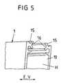
Figuren 1a und1b ; - Figur 5
- eine perspektivische Darstellung eines Ausschnittes des Trägerkörpers aus den
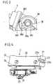
Figuren 1a und1b ; - Figuren 6a bis 6d
- vier Verfahrensschritte bei der Herstellung einer Verbindung zwischen Sicherungsvorrichtung und Montagefuß, um den Montagefuß mittels der Sicherungsvorrichtung in einer definierten Solllage am Trägerkörper zu positionieren;
- Figur 7a
- eine vergrößerte Darstellung der Verbindungsmittel der Sicherungsvorrichtung beim Einfahren in eine zugeordnete Verbindungsstelle des Montagefußes;
- Figur 7b
- das Zusammenwirken von Führungsmitteln der Sicherungsvorrichtung mit einer Führungsbahn des Trägerkörpers beim Einführen der Verbindungsmittel der Sicherungsvorrichtung in die Verbindungsstelle des Montagefußes gemäß
Figur 7a ; - Figuren 8a und 8b
- Darstellungen gemäß den
Figuren 7a bzw. 7b, wobei die Verbindungsmittel eine Rampe der Verbindungsstelle überfahren; - Figuren 9a und 9b
- Darstellungen gemäß den
Figuren 7a bzw. 7b nach Vollendung des Eingriffs der Verbindungsmittel in die Verbindungsstelle.
- Figure 1a
- a perspective view of a measuring device for determining the position of two relatively movable components with a carrier body for a longitudinal measuring graduation, with a measuring graduation scanning scanning device, which is guided longitudinally displaceably on the carrier body and which is fastened via a mounting foot on one of the mutually movable components, and with a securing device to hold the mounting foot in a defined desired position on the carrier body;
- FIG. 1b
- another perspective view of the measuring device
FIG. 1a , but without mounting foot; - FIGS. 2a and 2b
- two different perspective views of the safety device from the
FIGS. 1a and1b ; - FIG. 3
- a perspective view of a section of the securing device from the
FIGS. 1a and1b ; - FIG. 4
- a perspective view of the mounting foot of the
FIGS. 1a and1b ; - FIG. 5
- a perspective view of a section of the carrier body from the
FIGS. 1a and1b ; - FIGS. 6a to 6d
- four process steps in the preparation of a connection between the securing device and mounting foot to position the mounting foot by means of the securing device in a defined desired position on the support body;
- Figure 7a
- an enlarged view of the connecting means of the securing device when retracting into an associated connection point of the mounting foot;
- FIG. 7b
- the interaction of guide means of the securing device with a guideway of the carrier body during insertion of the connecting means of the securing device in the connection point of the mounting foot according to
Figure 7a ; - FIGS. 8a and 8b
- Representations according to the
FIGS. 7a or 7b, wherein the connecting means run over a ramp of the connection point; - FIGS. 9a and 9b
- Representations according to the
FIGS. 7a or 7b after completion of the engagement of the connecting means in the connection point.
In den
Der Trägerkörper 1 ist zur Befestigung an einem Maschinenbauteil, wie zum Beispiel dem Schlitten M1 einer Werkzeugmaschine, vorgesehen und ausgebildet, und weist ein längserstrecktes Hohlprofil 10 mit einer inneren Führungsbahn auf, die durch zwei parallel zueinander entlang der Erstreckungsrichtung E des Hohlprofils 10 verlaufende innere Führungen 16 gebildet wird. Neben jeder der inneren Führungen 16 erstreckt sich parallel eine äußere Führung 15.The
Dieses Hohlprofil 10 umschließt einen inneren Hohlraum H, in dem eine längserstreckte Messteilung 19 angeordnet ist.
Innerhalb des Hohlprofils 10 ist längsverschieblich ein Abtastwagen 29 einer Abtasteinrichtung 2 angeordnet, der zum Abtasten der Messteilung 19 des Trägerkörpers 1 beispielsweise eine Lichtquelle, ein Linsensystem und zugeordnete Fotoelemente trägt. Der Abtastwagen 29 ist in bekannter Weise über einen Mitnehmer 28 federnd, aber in Erstreckungsrichtung E des Hohlprofils 10 (Messrichtung) starr mit einem außerhalb der Hohlkammer H des Hohlprofils 10 angeordneten Montagefuß 20 verbunden. Der Montagefuß 20 dient zur Befestigung der Abtasteinrichtung 2 an einem zweiten Maschinenbauteil, wie beispielsweise dem Bett M2 der oben erwähnten Werkzeugmaschine. Die Verschieberichtung V der Abtasteinrichtung 2, also des Montagefußes 20 und des Abtastwagens 29 an dem Trägerkörper 1 entspricht der Erstreckungsrichtung E des Hohlprofils 10 und der darin angeordneten Messteilung 19.This
Within the
Eine Messeinrichtung der vorstehend beschriebenen Art ist allgemein bekannt und braucht daher hinsichtlich ihrer Funktion hier nicht näher erläutert zu werden.A measuring device of the type described above is well known and therefore need not be further explained in terms of their function here.
Gemäß den
Zur Festlegung des Grundkörpers 3 der Sicherungsvorrichtung 3, 4 an der einen Stirnseite 21 des Montagefußes 20 dient einerseits ein Steckerelement 32 in Form einer Andrücknase, das in einen zugeordneten Steckerbereich 23b in Form einer Ausnehmung an der einen Stirnseite 21 des Montagefußes 2 einführbar ist. Zum anderen dient hierzu ein Rastelement in Form eines federnden Rasthebels 31 mit einem Rastvorsprung 31a, der in eine zugeordnete Raststelle in Form einer Rastöffnung 23 mit einer Rastnut 23a an der einen Stirnseite 21 des Montagefußes 20 einrastbar ist.On the one hand, a
Zur Festlegung der beiden Schenkel 40 des Fortsatzes 4 der Sicherungsvorrichtung 3, 4 an dem Montagefuß 20 vor seiner anderen Stirnseite 22, die entlang der Erstreckungsrichtung E des Fortsatzes 4 von der einen Stirnseite 21 beabstandet ist, dienen an den Enden der beiden parallelen Schenkel 40 ausgebildete Verbindungsmittel 41, 41 a in Form jeweils einer von dem entsprechenden Schenkel 40 abgewinkelten Lasche 41 mit einer Andrücknase 41 a. Diese Verbindungsmittel 41, 41 a sind in eine (durch eine Nut gebildete) zugeordnete Verbindungsstelle 24 des Montagefußes 20 einführbar, wobei eine formschlüssige Verbindung zwischen den Schenkeln 40 des Fortsatzes 4 und dem Montagefuß 20 der Abtasteinrichtung 2 hergestellt wird. Die besagte Verbindungsstelle 24 des Montagefußes 20 befindet sich an der dem Trägerkörper 1 bzw. dessen Hohlprofil 10 zugewandten Oberfläche des Montagefußes 20 (und liegt in Erstreckungsrichtung E des Fortsatzes 4 vor der zweiten Stirnseite 22 des Montagefußes 20).To fix the two
Durch die vorstehend beschriebenen Maßnahmen lässt sich die Sicherungsvorrichtung 3, 4 einerseits im Bereich ihres Grundkörpers 3 und andererseits an dem dem Grundkörper 3 abgewandten Ende des Fortsatzes 4 jeweils im Bereich einer Stirnseite 21, 22 des Montagefußes 20 mit diesem verbinden. Zum Halten des Montagefußes 20 an dem Hohlprofil 10 des Trägerkörpers 1 in einer definierten Solllage ist es darüber hinaus erforderlich, die Sicherungsvorrichtung 3, 4 auch bezüglich des Hohlprofils 10 des Trägerkörpers 1 zu fixieren. Dies geschieht durch Klemmverbindungen, wie nachfolgend erläutert werden wird.By the measures described above, the securing
Anhand der
Die Position des Grundkörpers 3 bezüglich des Hohlprofils 10 des Trägerkörpers 1 in horizontaler Richtung senkrecht zur Verschieberichtung V (also in der durch die inneren Führungen 16 definierten Ebenen) wird außerdem dadurch festgelegt, dass der Grundkörper 3 mit zusätzlichen, äußeren Führungsmitteln 35 in jeweils einer äußeren Führung 15 des Hohlprofils 10 geführt ist, wobei sich jede der beiden äußeren Führungen 15 neben einer der inneren Führungen 16 des Hohlprofils 10 und parallel zu dieser erstreckt.The position of the
Darüber hinaus erfolgt eine klemmende Verbindung zwischen Sicherungsvorrichtung 3, 4 und Hohlprofil 10 des Trägerkörpers 1 auch im Bereich der vorderen Enden der Schenkel 40 des Fortsatzes 4 und zwar mittels dort vorgesehener Führungsmittel 46, 47. Die an jedem der beiden Schenkel 40 des Fortsatzes 4 im Bereich seines vorderen Endes angeordneten Führungsmittel 46, 47 werden jeweils gebildet durch einen ersten Führungsbereich 46, der sich in Erstreckungsrichtung E des Fortsatzes 4 unmittelbar an die Verbindungsmittel 41 des jeweiligen Schenkels 40 anschließt, sowie durch einen zweiten, entlang der Erstreckungsrichtung E hiervon beabstandeten Führungsbereich 47. Zumindest die ersten Führungsbereiche 46 am jeweiligen Schenkel 40 des Fortsatzes 4 werden beim Eingreifen der Verbindungsmittel 41 des jeweiligen Schenkels 40 in die zugeordnete Verbindungsstelle 24 des Montagefußes 20, aufgrund des Zusammenwirkens mit einer dort jeweils vorgesehenen Rampe 25, derart angehoben, dass sie klemmend gegen einen zugeordneten Anschlag der jeweiligen inneren Führung 16 des Hohlprofils 10 des Trägerkörpers 1 gedrückt werden und hierdurch an diesem klemmend befestigt sind, wodurch zugleich die Position des Fortsatzes 40 (und damit auch des daran festgelegten Montagefußes 20) bezüglich des Hohlprofils in vertikaler Richtung z senkrecht zur Erstreckungsrichtung E bzw. Verschieberichtung V festgelegt ist.In addition, a clamping connection between securing
Durch Betätigung des Klemmstückes 37 mittels der zugeordneten Rändelmutter 38 lassen sich insgesamt drei unterschiedliche Zustände des Grundkörpers 3 hinsichtlich seiner Positionierung am Hohlprofil 10 des Trägerkörpers 1 definieren. In dem einen Zustand ist das Klemmstück 37 mittels der Rändelmutter 38 soweit in vertikaler Richtung z angehoben, dass der Grundkörper 3 mittels der Klemmfüße 36 in den zugeordneten inneren Führungen 16 des Hohlprofils-10 klemmend befestigt ist. In dem anderen Zustand befindet sich das Klemmstück 37 in einer Position, in der es die Klemmfüße 36 des Grundkörpers 3 nicht auseinander drückt, so dass sich dieser in Verschieberichtung V in den inneren Führungen 16 sowie den äußeren Führungen 15 des Hohlprofils 10 verschieben lässt. In einem dritten Zustand schließlich ist das Klemmstück 37 so weit von dem Grundkörper 3 gelöst, so dass sich dieser von dem Hohlprofil 10 des Trägerkörpers 1 abnehmen lässt. Diese unterschiedlichen Zustände hinsichtlich der Befestigung des Grundkörpers 3 am Hohlprofil 10 entsprechen unterschiedlichen Positionen der Rändelmutter 38, denen jeweils entsprechende Raststellen 38a, 38b, 38c der Rändelmutter 38 zugeordnet sind. In jedem der drei vorbeschriebenen Zustände befindet sich eine dieser Raststellen 38a, 38b, 38c in Eingriff mit einem zugeordneten Rastelement 39 des Grundkörpers 3 in Form eines Rasthakens. Hierdurch lassen sich die entsprechenden Zustände mittels der Rändelmutter 38 definiert einstellen und die Rändelmutter 38 kann in einer dem jeweiligen Zustand entsprechenden Position gehalten werden.By operating the clamping
Ferner ist eine Rücklaufsperre 380, 381 vorgesehen, die verhindert, dass sich das Betätigungselement in Form einer Rändelmutter so weit in Löserichtung dreht, dass das Klemmstück 37 sich vollständig von dem Grundkörper 3 löst. Die Rücklaufsperre 380, 381 umfasst ein an der Rändelmutter 38 ausgebildetes elastisches Sperrmittel in Form einer Nase 380 sowie ein an dem Grundkörper 3 ausgebildetes Sperrelement 381. Bei einer Drehbewegung der Rändelmutter 38 in Fixierungsrichtung (also in
Im Folgenden wird nun anhand der
Gemäß
Während des Einschiebens des Rasthebels 31 und der Andrücknase 32 des Grundkörpers 3 in die zugeordnete Rastöffnung 23 bzw. Ausnehmung 23b des Montagefußes 20 treten die an den vorderen Enden der Schenkel 40 des Fortsatzes 4 vorgesehenen Verbindungsmittel 41 in Eingriff mit den zugeordneten Verbindungsstellen 24 im Bereich der anderen Stirnseite 22 des Montagefußes 20, wie nachfolgend anhand der
In dem in
Vor dem Erreichen dieses horizontalen Formschlusses durchfahren die Verbindungsmittel 41, 41 a jeweils eine am Montagefuß 20 vorgesehene Fase 26, die als Einführfase wirkt und vor dem Erreichen der in
Anhand
Bei einem weiteren Verschieben des Grundkörpers 3 und des Fortsatzes 4 der Sicherungsvorrichtung 3, 4 in Verschieberichtung V, so dass der Rasthebel 31 (vergl.
Gleichzeitig werden die vorderen Führungsbereiche 46 (aufgrund des Anfahrens der Rampen 25) in vertikaler Richtung z in Richtung auf die oberen Anschläge 16a der inneren Führungen 16 des Hohlprofils 10 angehoben, vergl.
In den
Somit ist durch die Befestigung des Grundkörpers 3 an der einen Stirnseite 21 des Montagefußes 20 (wie in den
Das heißt, für das Herstellen der Verbindungen zwischen dem Fortsatz 4 und dem Montagefuß 20 sowie zwischen dem Fortsatz 4 und dem Trägerkörper 10 sind keine zusätzlichen Montageschritte neben dem ohnehin vorgesehenen Festlegen des Grundkörpers 3 der Sicherungsvorrichtung 3, 4 am Montagefuß 20 durch Verschieben entlang des Trägerkörpers 1 erforderlich.That is, for making the connections between the
Abschließend wird dann lediglich noch der Grundkörper 20 in der vorstehend anhand der
Die vorstehend beschriebene Sicherungsvorrichtung 3, 4 zeichnet sich zusammenfassend dadurch aus, dass zu deren form- und kraftschlüssiger Befestigung an dem Montagefuß 20 der Abtasteinheit 2 sowie an dem Hohlprofil 10 des Trägerkörpers 1 keine zusätzlichen Werkzeuge, wie zum Beispiel Schraubendreher, erforderlich sind, sondem dass hierfür lediglich der Grundkörper 3 der Sicherungsvorrichtung 3, 4 in Anschlag mit der einen Stirnseite 21 des Montagefußes 20 gebracht werden muss, wobei automatisch die Steck- und Rastverbindungen zwischen Sicherungsvorrichtung 3, 4 und Montagefuß 20 geschaffen werden sowie außerdem eine Klemmverbindung zwischen dem Fortsatz 4 der Sicherungsvorrichtung 3, 4 und dem Hohlprofil 10 des Trägerkörpers 1 erzeugt wird. Abschließend wird dann mittels der Rändelmutter 38 die klemmschlüssige Verbindung zwischen dem Grundkörper 3 und dem Hohlprofil 10 hergestellt. In entsprechender Weise ist auch eine Demontage der Sicherungsvorrichtung 3, 4 ohne Werkzeug möglich.The securing
Die Sicherungsvorrichtung kann mittels der Rändelmutter 38 in drei unterschiedliche Zustände gebracht werden, wobei sie in dem einen Zustand an dem Hohlprofil 10 des Trägerkörpers 1 festgeklemmt ist, um die Abtasteinheit 2 an dem Trägerkörper 1 in einer definierten Solllage zu halten und die Einhaltung von Montagetoleranzen beim Einbau der Messeinrichtung in eine Werkzeugmaschine zu gewährleisten. In einem zweiten Zustand lässt sich die Sicherungsvorrichtung 3, 4 zusammen mit der Abtasteinheit 2 entlang der Erstreckungsrichtung E des Hohlprofils 10 bzw. des Trägerkörpers 1 verschieben, um die Abtasteinheit in eine bestimmte, vorgebbare Position bringen zu können. Im dritten Zustand schließlich liegt die Sicherungsvorrichtung 3, 4 lediglich lose auf dem Trägerkörper 1 auf und lässt sich von diesem entnehmen.The securing device can be brought by means of the
Die vorbeschriebene Sicherungsvorrichtung hat ferner die Vorteile, dass beide Seiten der Messeinrichtung 1, 2 als Montageflächen verwendet werden können, so dass eine Kabelabgangsrichtung frei gewählt werden kann, dass die Sicherungsvorrichtung bei gleichzeitiger Verwendung einer Montageschiene einsetzbar ist sowie dass keine den Trägerkörper 1 und den Montagefuß 20 umgreifenden Elemente erforderlich sind, um Anschlagflächen bei der Montage frei zu halten.The above-described securing device further has the advantages that both sides of the measuring
Claims (45)
- A securing device for the transport and the mounting of a measuring device for determining the position of two components (M1, M2), which can be moved relative to one another and which comprise a measuring scale (19), which extends longitudinally, a support body (1) for the measuring scale (19), a scanner (2), which scans the measuring scale (19) and which is guided at a defined distance from the measuring scale (19), and a mounting foot (20) for attaching the scanner (2) to one of the components (M2), which are movable relative to one another, wherein the securing device comprises a base body (3), which can be displaced longitudinally along a guide track of the support body and which can be fixed to the mounting foot (20) on the one side and to the support body (1) on the other side, so as to hold the mounting foot (20) in a desired position with reference to the support body (1) and wherein an extension (4), which extends along the measuring scale (19), projects from the base body (3),
characterized in
that provision is made on the extension (4) for connecting means (41, 41a), which can be automatically engaged with an assigned junction (24) of the mounting foot (20). - The securing device according to claim 1,characterized in that the connecting means (41, 41a) can be engaged with the junction (24) by displacing the base body (3) in the direction of extension (E) of the extension (4).
- The securing device according to claim 1 or 2,characterized in that the connecting means (41, 41a) are spaced apart from the base body (3) in the direction of extension (E) of the extension (4) andin that the connecting means (41, 41a) are preferably provided on one end of the extension (4), which is spaced apart from the base body (3).
- The securing device according to one of the preceding claims,characterized in that the connecting means (41, 41a) are integrally molded on the extension (4) in one piece.
- The securing device according to one of the preceding claims,characterized in that the connecting means (41, 41a) of the extension (4) can be inserted into the assigned junction (24) of the mounting foot (20).
- The securing device according to one of the preceding claims,characterized in that the connecting means (41, 41a) are embodied for establishing a plug-in connection.
- The securing device according to one of the preceding claims,characterized in that the connecting means (41, 41a) are embodied for establishing a positive connection.
- The securing device according to one of the preceding claims,characterized in that the extension (4) is angled in the area of the connecting means (41, 41a) such that the connecting means (41, 41a) can glide across a ramp (25) of the junction (24).
- The securing device according to one of the preceding claims,characterized in that the section of the extension (4), which is provided with the connecting means (41, 41a) can be moved by means of elastic deformation at right angles to the direction of extension (E) of the extension (4).
- The securing device according to one of the preceding claims,characterized in that the connecting means (41, 41a) encompass at least one pressure nose (41a), which can engage with the junction (24).
- The securing device according to one of the preceding claims,characterized in that the extension (4) is integrally molded on the base body (3) in one piece.
- The securing device according to one of the preceding claims,characterized in that provision is made on the extension (4) for guide means (46, 47), by means of which the extension (4) can be displaced along an assigned guide device (16) of the support body (1) in the direction of extension (E) of the measuring scale (19).
- The securing device according to claim 12,characterized in that the guide means (46, 47) connect to the connecting means (41, 41a) in the direction of extension (E) of the extension (4).
- The securing device according to claim 12 or 13,characterized in that provision is made on the extension (4) for two guide areas (46 and 47) of the guide means (46, 47), which are spaced apart from one another in the direction of extension (E) of the extension (4).
- The securing device according to one of the preceding claims,characterized in that the extension (4) encompasses two journals (40), which extend substantially parallel to one another and which are in each case provided with connecting means (41, 41a).
- The securing device according to one of the preceding claims,characterized in that the base body (3) can be attached to the mounting foot (20) by displacing along the guide track (16) of the support body (1).
- The securing device according to claim 16,characterized in that the base body (3) can be attached to the mounting foot (20) in a positive fit, in particular by means of a snap-in connection (23, 23a, 31, 31a) and/or by means of a plug-in connection (23b, 32).
- The securing device according to claim 17,characterized in that the base body (3) encompasses at least one plug element (32) for plugging into a plug area (23b) of the mounting foot (20).
- The securing device according to claim 18,characterized in that the plug element (32) is formed by means of a projection, in particular by means of a pressure nose, for plugging into a recess (23b) of the mounting foot (20).
- The securing device according to claim 17,characterized in that the base body (3) encompasses at least one snap-in element (31) for snapping into a snap-in location (23) of the mounting foot (20).
- The securing device according to claim 20,characterized in that the snap-in element (31) is formed by means of a snap-in lever, which can be snapped into a snap-in opening (23).
- The securing device according to one of the preceding claims,characterized in that the base body (3) encompasses a clamping device (36, 37) for fixedly clamping to the support body (1).
- The securing device according to one of the preceding claims,characterized in that the base body (3) encompasses guide means (35, 36), by means of which it can be displaced along the guide track (15, 16) of the support body (1) in the direction of extension (E) of the measuring scale (19).
- The securing device according to claim 22 and 23,characterized in that the guide means (35, 36) can be clamped to the guide track (15, 16) of the support body (1) by means of the clamping device (36, 37).
- The securing device according to claim 24,characterized in that provision is made on the base body (3) for an actuating element (38), which acts on a clamping element (37) of the clamping device (36, 37) for actuating the clamping device (36, 37).
- The securing device according to claim 25,characterized in that the actuating element (38) is embodied so as to be rotatable and is formed in particular by means of a knurled screw or knurled nut.
- The securing device according to claim 25 or 26,characterized in that provision is made on the actuating element (38) for locking means (380), which can interact with an assigned locking element (381) of the base body (3), so as to define a resetting motion of the actuating element (38).
- The securing device according to one of claims 25 to 27,characterized in that provision is made on the actuating element (38) for snap-in locations (38a, 38b, 38c), so as to be able to lock the actuating element (38) in different positions, which correspond in each case to the clamping device (36, 37), which can be actuated by means of the actuating element (38).
- The securing device according to one of claims 25 to 27,characterized in that provision is made on the actuating element (38) for markings, which represent the different states of the clamping device (36, 37), which can be actuated by means of the actuating element (38).
- A measuring device for determining the position of two components (M1, M2), which can be moved relative to one another, comprising- a measuring scale (19) extending longitudinally,- a support body (1) for the measuring scale (19),- a scanner (2), which scans the measuring scale (19) and which is guided at a defined distance from the measuring scale (19),- a mounting foot (20) for attaching the scanner (2) to one of the components (M2), which can be moved relative to one another and- a securing device comprising a base body (3), which can be longitudinally displaced along a guide track of the support body (1) and which can be fixed to the mounting foot (20) on the one side and to the support body (1) on the other side, so as to hold the mounting foot (20) in a desired position with reference to the support body (1),characterized by
an embodiment of the securing device (3, 4) according to one of claims 1 to 29. - The measuring device according to claim 30,characterized in that the mounting foot (20) encompasses to front faces (21, 22), which are spaced apart from one another along the direction of extension (E) of the measuring scale (19), wherein the base body (3) can be fixed to the one front side (21) of the mounting foot (20) and the extension (4) can be fixed on the mounting foot (20) at a junction (24), which is spaced apart from this front side (21) in the direction of extension (E) of the measuring scale (19).
- The measuring device according to claim 30 or 31,characterized in that provision is made on the mounting foot (20) for a junction (24), with which the connecting means (41, 41a) of the extension (4) engage automatically when the base body (3) is fixed to the mounting foot (20).
- The measuring device according to claim 32,characterized in that the connecting means (41, 41a) snap into the junction (40) when the base body (3) is displaced along the guide track (15, 16) of the support body (1) for attaching to the mounting foot (20).
- The measuring device according to claim 32 or 33,characterized in that the connecting means (41, 41a) can be engaged in a positive fit with the junction (24) of the mounting foot (20).
- The measuring device according to one of claims 32 to 34,characterized in that the junction (24) encompasses a ramp (25), by means of which the extension (4) can be moved along a direction (z) at right angles to the direction of extension (E) of the measuring scale (19) in the area of the connecting means (41, 41a) of said extension (4).
- The measuring device according to claim 35, comprising a securing device according to one of claims 12 to 14,characterized in that the connecting means (41, 41a) can be moved at right angles to the direction of extension (E) of the measuring scale (19) by means of the ramp (25) such that the guide means (46) of the extension (4) are pressed against a stop (16a) of the assigned guide track (16) of the support body (1).
- The measuring device according to one of claims 30 to 36,characterized in that the extension (4) extends between the mounting foot (20) and the support body (1).
- The measuring device according to one of claims 30 to 37,characterized in that provision is made on the mounting foot (20) for an insertion nose (26), so as to facilitate the supply of the connecting means (41, 41a) to the junction (24) of the mounting foot (20).
- The measuring device according to one of claims 30 to 38, comprising a securing device according to claim 15,characterized in that the mounting foot (20) encompasses two junctions (24), which are in each case assigned to one of the connection means (41, 41a) of the extension (4).
- The measuring device according to one of claims 30 to 39, comprising a securing device according to claim 18 or 19,characterized in that provision is made on the mounting foot (20) for a plug-in area (23b) for inserting the plug-in element (32) of the base body (3).
- The measuring device according to one of claims 30 to 40, comprising a securing device according to claim 20 or 21,characterized in that provision is made on the mounting foot (20) for a snap-in location (23) for engaging the snap-in element (31) of the base body (3).
- The measuring device according to one of claims 30 to 41, comprising a securing device according to claim 27,characterized in that a locking element (381) of the base body (3) is assigned to the locking means (380) of the actuating element (38) for forming a backstop.
- The measuring device according to one of claims 30 to 42, comprising a securing device according to claim 28,characterized in that provision is made on the base body (3) for a snap-in element (39) for snapping into the snap-in locations (38a, 38b, 38c) of the actuating element (38).
- The measuring device according to one of the preceding claims,characterized in that the guide track (15, 16) of the support body (1) encompasses first guides (16), to which the securing device (3, 4) can be clamped.
- The measuring device according to claim 44,characterized in that second guides (15) run parallel to the first guides (16) on the support body (43), so as to fix the position of the securing device (3, 4) in the plane, which is defined by the guides (15, 16), at right angles to the direction of extension (E) of the measuring scale (19).
Applications Claiming Priority (2)
| Application Number | Priority Date | Filing Date | Title |
|---|---|---|---|
| DE10347965 | 2003-10-10 | ||
| DE10347965ADE10347965A1 (en) | 2003-10-10 | 2003-10-10 | Safety device for the transport and installation of a measuring device |
Publications (2)
| Publication Number | Publication Date |
|---|---|
| EP1522826A1 EP1522826A1 (en) | 2005-04-13 |
| EP1522826B1true EP1522826B1 (en) | 2011-01-19 |
Family
ID=34306411
Family Applications (1)
| Application Number | Title | Priority Date | Filing Date |
|---|---|---|---|
| EP04022640AExpired - LifetimeEP1522826B1 (en) | 2003-10-10 | 2004-09-23 | Securing device for transporting and mounting a measuring assembly |
Country Status (7)
| Country | Link |
|---|---|
| US (1) | US7143523B2 (en) |
| EP (1) | EP1522826B1 (en) |
| JP (1) | JP2005114719A (en) |
| CN (1) | CN1605828A (en) |
| AT (1) | ATE496281T1 (en) |
| DE (2) | DE10347965A1 (en) |
| ES (1) | ES2358590T3 (en) |
Families Citing this family (9)
| Publication number | Priority date | Publication date | Assignee | Title |
|---|---|---|---|---|
| DE10329374A1 (en)* | 2003-06-30 | 2005-01-20 | Dr. Johannes Heidenhain Gmbh | Scanning unit of a position measuring device |
| DE102005013364A1 (en)* | 2004-05-18 | 2005-12-15 | Dr. Johannes Heidenhain Gmbh | Position measuring device |
| DE102004035299B4 (en)* | 2004-07-21 | 2015-07-09 | Dr. Johannes Heidenhain Gmbh | Mounting aid of a position measuring device |
| US7735513B2 (en)* | 2004-10-08 | 2010-06-15 | I-Con Systems, Inc. | Diaphragm valve with electronic pressure detection |
| DE102005060687A1 (en)* | 2005-12-15 | 2007-06-21 | Dr. Johannes Heidenhain Gmbh | Safety device for the transport and installation of a measuring device |
| DE102006031756A1 (en)* | 2006-07-04 | 2008-01-10 | Dr. Johannes Heidenhain Gmbh | Position measuring device for determining the position of two relatively movable components |
| JP4956263B2 (en)* | 2007-04-20 | 2012-06-20 | 株式会社ミツトヨ | Holding device and measuring device |
| JP5264385B2 (en)* | 2008-09-19 | 2013-08-14 | 株式会社森精機製作所 | Holding device |
| ES2702948T3 (en)* | 2016-07-27 | 2019-03-06 | Heidenhain Gmbh Dr Johannes | Equipment for measuring lengths |
Family Cites Families (8)
| Publication number | Priority date | Publication date | Assignee | Title |
|---|---|---|---|---|
| AT379449B (en)* | 1984-07-03 | 1986-01-10 | R S F Elektronik Ohg Rechtsfor | LENGTH MEASURING DEVICE |
| US5258931A (en)* | 1988-07-08 | 1993-11-02 | Parker-Hannifin Corporation | Precision electronic absolute and relative position sensing device and method of using same |
| DE19526517C2 (en)* | 1995-07-20 | 2000-08-24 | Zeiss Carl Jena Gmbh | Arrangement for attaching a length measuring device |
| DE19918654B4 (en)* | 1999-04-16 | 2004-07-15 | Dr. Johannes Heidenhain Gmbh | Safety device for the transport and assembly of a measuring device |
| JP3943498B2 (en)* | 2000-12-22 | 2007-07-11 | ドクトル・ヨハネス・ハイデンハイン・ゲゼルシヤフト・ミツト・ベシユレンクテル・ハフツング | Length measuring device |
| DE10109909C2 (en)* | 2001-02-20 | 2003-12-04 | Heidenhain Gmbh Dr Johannes | Safety device for the transport and assembly of a measuring device |
| JP4423851B2 (en)* | 2002-02-28 | 2010-03-03 | 日本精工株式会社 | Method for manufacturing linear motion guide device |
| DE10329374A1 (en)* | 2003-06-30 | 2005-01-20 | Dr. Johannes Heidenhain Gmbh | Scanning unit of a position measuring device |
- 2003
- 2003-10-10DEDE10347965Apatent/DE10347965A1/ennot_activeWithdrawn
- 2004
- 2004-09-17JPJP2004270684Apatent/JP2005114719A/ennot_activeWithdrawn
- 2004-09-23EPEP04022640Apatent/EP1522826B1/ennot_activeExpired - Lifetime
- 2004-09-23DEDE502004012123Tpatent/DE502004012123D1/ennot_activeExpired - Lifetime
- 2004-09-23ESES04022640Tpatent/ES2358590T3/ennot_activeExpired - Lifetime
- 2004-09-23ATAT04022640Tpatent/ATE496281T1/enactive
- 2004-10-05USUS10/958,599patent/US7143523B2/ennot_activeExpired - Fee Related
- 2004-10-10CNCN200410085230.9Apatent/CN1605828A/enactivePending
Also Published As
| Publication number | Publication date |
|---|---|
| JP2005114719A (en) | 2005-04-28 |
| EP1522826A1 (en) | 2005-04-13 |
| US20050076527A1 (en) | 2005-04-14 |
| CN1605828A (en) | 2005-04-13 |
| US7143523B2 (en) | 2006-12-05 |
| ES2358590T3 (en) | 2011-05-12 |
| DE10347965A1 (en) | 2005-05-04 |
| ATE496281T1 (en) | 2011-02-15 |
| DE502004012123D1 (en) | 2011-03-03 |
Similar Documents
| Publication | Publication Date | Title |
|---|---|---|
| DE202004002321U1 (en) | Positioning device for a multi-segment slide rail device for drawers | |
| EP2372172B1 (en) | Device with at least two parts that can be moved relative to each other | |
| EP2287974A1 (en) | Electric push-pull connector | |
| DE69123335T2 (en) | Device for adjusting the length of a rod, in particular a rod for the operation of a vehicle lock | |
| EP1522826B1 (en) | Securing device for transporting and mounting a measuring assembly | |
| DE4004197C2 (en) | Quick connection device for furniture hinges | |
| EP1275541A1 (en) | Module, specially a sliding roof module for a vehicle | |
| EP0605782B1 (en) | Joint device for face plates | |
| EP2228503A1 (en) | Paneel | |
| EP3608588B1 (en) | Holder spring for light | |
| EP1798527B1 (en) | Securing device for the transport and assembly of a measuring apparatus | |
| EP2389488B1 (en) | Floor covering made of a composite board | |
| DE19923487B4 (en) | Abutment with molding for attaching control cables | |
| EP3643565B1 (en) | Device, system and method for securing a load in a vehicle | |
| WO2015074933A1 (en) | Holding device for a housing and method for mounting the housing using the holding device | |
| EP1622731A1 (en) | Tool-receiving device | |
| EP1751437B1 (en) | Position measuring device | |
| EP0104340A2 (en) | Arrangement, in particular for a shower partition wall | |
| EP3945936B1 (en) | Retraction or ejection device | |
| DE69510627T2 (en) | Device support device To be installed on a cable duct body | |
| DE202009014693U1 (en) | fitting assembly | |
| DE29812988U1 (en) | Fixing device for bones arranged side by side and application instrument therefor | |
| EP4407136B1 (en) | Corner connector with expanding element | |
| EP2997315B1 (en) | System for fixing mounting rails | |
| EP0197376B1 (en) | Socket for a component |
Legal Events
| Date | Code | Title | Description |
|---|---|---|---|
| PUAI | Public reference made under article 153(3) epc to a published international application that has entered the european phase | Free format text:ORIGINAL CODE: 0009012 | |
| AK | Designated contracting states | Kind code of ref document:A1 Designated state(s):AT BE BG CH CY CZ DE DK EE ES FI FR GB GR HU IE IT LI LU MC NL PL PT RO SE SI SK TR | |
| AX | Request for extension of the european patent | Extension state:AL HR LT LV MK | |
| 17P | Request for examination filed | Effective date:20051013 | |
| AKX | Designation fees paid | Designated state(s):AT BE BG CH CY CZ DE DK EE ES FI FR GB GR HU IE IT LI LU MC NL PL PT RO SE SI SK TR | |
| GRAP | Despatch of communication of intention to grant a patent | Free format text:ORIGINAL CODE: EPIDOSNIGR1 | |
| GRAS | Grant fee paid | Free format text:ORIGINAL CODE: EPIDOSNIGR3 | |
| GRAA | (expected) grant | Free format text:ORIGINAL CODE: 0009210 | |
| AK | Designated contracting states | Kind code of ref document:B1 Designated state(s):AT BE BG CH CY CZ DE DK EE ES FI FR GB GR HU IE IT LI LU MC NL PL PT RO SE SI SK TR | |
| REG | Reference to a national code | Ref country code:GB Ref legal event code:FG4D Free format text:NOT ENGLISH | |
| REG | Reference to a national code | Ref country code:CH Ref legal event code:EP | |
| REG | Reference to a national code | Ref country code:IE Ref legal event code:FG4D Free format text:LANGUAGE OF EP DOCUMENT: GERMAN | |
| REF | Corresponds to: | Ref document number:502004012123 Country of ref document:DE Date of ref document:20110303 Kind code of ref document:P | |
| REG | Reference to a national code | Ref country code:DE Ref legal event code:R096 Ref document number:502004012123 Country of ref document:DE Effective date:20110303 | |
| REG | Reference to a national code | Ref country code:ES Ref legal event code:FG2A Ref document number:2358590 Country of ref document:ES Kind code of ref document:T3 Effective date:20110429 | |
| REG | Reference to a national code | Ref country code:NL Ref legal event code:VDEP Effective date:20110119 | |
| PG25 | Lapsed in a contracting state [announced via postgrant information from national office to epo] | Ref country code:SE Free format text:LAPSE BECAUSE OF FAILURE TO SUBMIT A TRANSLATION OF THE DESCRIPTION OR TO PAY THE FEE WITHIN THE PRESCRIBED TIME-LIMIT Effective date:20110119 Ref country code:PT Free format text:LAPSE BECAUSE OF FAILURE TO SUBMIT A TRANSLATION OF THE DESCRIPTION OR TO PAY THE FEE WITHIN THE PRESCRIBED TIME-LIMIT Effective date:20110519 Ref country code:GR Free format text:LAPSE BECAUSE OF FAILURE TO SUBMIT A TRANSLATION OF THE DESCRIPTION OR TO PAY THE FEE WITHIN THE PRESCRIBED TIME-LIMIT Effective date:20110420 | |
| REG | Reference to a national code | Ref country code:IE Ref legal event code:FD4D | |
| PG25 | Lapsed in a contracting state [announced via postgrant information from national office to epo] | Ref country code:NL Free format text:LAPSE BECAUSE OF FAILURE TO SUBMIT A TRANSLATION OF THE DESCRIPTION OR TO PAY THE FEE WITHIN THE PRESCRIBED TIME-LIMIT Effective date:20110119 Ref country code:CY Free format text:LAPSE BECAUSE OF FAILURE TO SUBMIT A TRANSLATION OF THE DESCRIPTION OR TO PAY THE FEE WITHIN THE PRESCRIBED TIME-LIMIT Effective date:20110119 Ref country code:BG Free format text:LAPSE BECAUSE OF FAILURE TO SUBMIT A TRANSLATION OF THE DESCRIPTION OR TO PAY THE FEE WITHIN THE PRESCRIBED TIME-LIMIT Effective date:20110419 Ref country code:SI Free format text:LAPSE BECAUSE OF FAILURE TO SUBMIT A TRANSLATION OF THE DESCRIPTION OR TO PAY THE FEE WITHIN THE PRESCRIBED TIME-LIMIT Effective date:20110119 Ref country code:PL Free format text:LAPSE BECAUSE OF FAILURE TO SUBMIT A TRANSLATION OF THE DESCRIPTION OR TO PAY THE FEE WITHIN THE PRESCRIBED TIME-LIMIT Effective date:20110119 Ref country code:FI Free format text:LAPSE BECAUSE OF FAILURE TO SUBMIT A TRANSLATION OF THE DESCRIPTION OR TO PAY THE FEE WITHIN THE PRESCRIBED TIME-LIMIT Effective date:20110119 | |
| PG25 | Lapsed in a contracting state [announced via postgrant information from national office to epo] | Ref country code:DK Free format text:LAPSE BECAUSE OF FAILURE TO SUBMIT A TRANSLATION OF THE DESCRIPTION OR TO PAY THE FEE WITHIN THE PRESCRIBED TIME-LIMIT Effective date:20110119 Ref country code:IE Free format text:LAPSE BECAUSE OF FAILURE TO SUBMIT A TRANSLATION OF THE DESCRIPTION OR TO PAY THE FEE WITHIN THE PRESCRIBED TIME-LIMIT Effective date:20110119 Ref country code:EE Free format text:LAPSE BECAUSE OF FAILURE TO SUBMIT A TRANSLATION OF THE DESCRIPTION OR TO PAY THE FEE WITHIN THE PRESCRIBED TIME-LIMIT Effective date:20110119 | |
| PLBE | No opposition filed within time limit | Free format text:ORIGINAL CODE: 0009261 | |
| STAA | Information on the status of an ep patent application or granted ep patent | Free format text:STATUS: NO OPPOSITION FILED WITHIN TIME LIMIT | |
| PG25 | Lapsed in a contracting state [announced via postgrant information from national office to epo] | Ref country code:SK Free format text:LAPSE BECAUSE OF FAILURE TO SUBMIT A TRANSLATION OF THE DESCRIPTION OR TO PAY THE FEE WITHIN THE PRESCRIBED TIME-LIMIT Effective date:20110119 Ref country code:CZ Free format text:LAPSE BECAUSE OF FAILURE TO SUBMIT A TRANSLATION OF THE DESCRIPTION OR TO PAY THE FEE WITHIN THE PRESCRIBED TIME-LIMIT Effective date:20110119 Ref country code:RO Free format text:LAPSE BECAUSE OF FAILURE TO SUBMIT A TRANSLATION OF THE DESCRIPTION OR TO PAY THE FEE WITHIN THE PRESCRIBED TIME-LIMIT Effective date:20110119 | |
| 26N | No opposition filed | Effective date:20111020 | |
| PG25 | Lapsed in a contracting state [announced via postgrant information from national office to epo] | Ref country code:IT Free format text:LAPSE BECAUSE OF FAILURE TO SUBMIT A TRANSLATION OF THE DESCRIPTION OR TO PAY THE FEE WITHIN THE PRESCRIBED TIME-LIMIT Effective date:20110119 | |
| REG | Reference to a national code | Ref country code:DE Ref legal event code:R097 Ref document number:502004012123 Country of ref document:DE Effective date:20111020 | |
| BERE | Be: lapsed | Owner name:DR. JOHANNES HEIDENHAIN G.M.B.H. Effective date:20110930 | |
| PG25 | Lapsed in a contracting state [announced via postgrant information from national office to epo] | Ref country code:MC Free format text:LAPSE BECAUSE OF NON-PAYMENT OF DUE FEES Effective date:20110930 | |
| REG | Reference to a national code | Ref country code:CH Ref legal event code:PL | |
| GBPC | Gb: european patent ceased through non-payment of renewal fee | Effective date:20110923 | |
| REG | Reference to a national code | Ref country code:FR Ref legal event code:ST Effective date:20120531 | |
| PG25 | Lapsed in a contracting state [announced via postgrant information from national office to epo] | Ref country code:BE Free format text:LAPSE BECAUSE OF NON-PAYMENT OF DUE FEES Effective date:20110930 | |
| PG25 | Lapsed in a contracting state [announced via postgrant information from national office to epo] | Ref country code:LI Free format text:LAPSE BECAUSE OF NON-PAYMENT OF DUE FEES Effective date:20110930 Ref country code:CH Free format text:LAPSE BECAUSE OF NON-PAYMENT OF DUE FEES Effective date:20110930 | |
| PG25 | Lapsed in a contracting state [announced via postgrant information from national office to epo] | Ref country code:GB Free format text:LAPSE BECAUSE OF NON-PAYMENT OF DUE FEES Effective date:20110923 Ref country code:FR Free format text:LAPSE BECAUSE OF NON-PAYMENT OF DUE FEES Effective date:20110930 | |
| REG | Reference to a national code | Ref country code:AT Ref legal event code:MM01 Ref document number:496281 Country of ref document:AT Kind code of ref document:T Effective date:20110923 | |
| PG25 | Lapsed in a contracting state [announced via postgrant information from national office to epo] | Ref country code:AT Free format text:LAPSE BECAUSE OF NON-PAYMENT OF DUE FEES Effective date:20110923 | |
| PG25 | Lapsed in a contracting state [announced via postgrant information from national office to epo] | Ref country code:LU Free format text:LAPSE BECAUSE OF NON-PAYMENT OF DUE FEES Effective date:20110923 | |
| PG25 | Lapsed in a contracting state [announced via postgrant information from national office to epo] | Ref country code:TR Free format text:LAPSE BECAUSE OF FAILURE TO SUBMIT A TRANSLATION OF THE DESCRIPTION OR TO PAY THE FEE WITHIN THE PRESCRIBED TIME-LIMIT Effective date:20110119 | |
| PG25 | Lapsed in a contracting state [announced via postgrant information from national office to epo] | Ref country code:HU Free format text:LAPSE BECAUSE OF FAILURE TO SUBMIT A TRANSLATION OF THE DESCRIPTION OR TO PAY THE FEE WITHIN THE PRESCRIBED TIME-LIMIT Effective date:20110119 | |
| PGFP | Annual fee paid to national office [announced via postgrant information from national office to epo] | Ref country code:ES Payment date:20181022 Year of fee payment:15 | |
| REG | Reference to a national code | Ref country code:ES Ref legal event code:FD2A Effective date:20210128 | |
| PG25 | Lapsed in a contracting state [announced via postgrant information from national office to epo] | Ref country code:ES Free format text:LAPSE BECAUSE OF NON-PAYMENT OF DUE FEES Effective date:20190924 | |
| PGFP | Annual fee paid to national office [announced via postgrant information from national office to epo] | Ref country code:DE Payment date:20220620 Year of fee payment:19 | |
| REG | Reference to a national code | Ref country code:DE Ref legal event code:R119 Ref document number:502004012123 Country of ref document:DE | |
| PG25 | Lapsed in a contracting state [announced via postgrant information from national office to epo] | Ref country code:DE Free format text:LAPSE BECAUSE OF NON-PAYMENT OF DUE FEES Effective date:20240403 |