EP1522499A2 - Child-resistant closure and container package - Google Patents
Child-resistant closure and container packageDownload PDFInfo
- Publication number
- EP1522499A2 EP1522499A2EP04078578AEP04078578AEP1522499A2EP 1522499 A2EP1522499 A2EP 1522499A2EP 04078578 AEP04078578 AEP 04078578AEP 04078578 AEP04078578 AEP 04078578AEP 1522499 A2EP1522499 A2EP 1522499A2
- Authority
- EP
- European Patent Office
- Prior art keywords
- thread
- closure
- finish
- set forth
- container
- Prior art date
- Legal status (The legal status is an assumption and is not a legal conclusion. Google has not performed a legal analysis and makes no representation as to the accuracy of the status listed.)
- Granted
Links
Images


Classifications
- B—PERFORMING OPERATIONS; TRANSPORTING
- B65—CONVEYING; PACKING; STORING; HANDLING THIN OR FILAMENTARY MATERIAL
- B65D—CONTAINERS FOR STORAGE OR TRANSPORT OF ARTICLES OR MATERIALS, e.g. BAGS, BARRELS, BOTTLES, BOXES, CANS, CARTONS, CRATES, DRUMS, JARS, TANKS, HOPPERS, FORWARDING CONTAINERS; ACCESSORIES, CLOSURES, OR FITTINGS THEREFOR; PACKAGING ELEMENTS; PACKAGES
- B65D41/00—Caps, e.g. crown caps or crown seals, i.e. members having parts arranged for engagement with the external periphery of a neck or wall defining a pouring opening or discharge aperture; Protective cap-like covers for closure members, e.g. decorative covers of metal foil or paper
- B65D41/02—Caps or cap-like covers without lines of weakness, tearing strips, tags, or like opening or removal devices
- B65D41/04—Threaded or like caps or cap-like covers secured by rotation
- B65D41/0471—Threaded or like caps or cap-like covers secured by rotation with means for positioning the cap on the container, or for limiting the movement of the cap, or for preventing accidental loosening of the cap
- B—PERFORMING OPERATIONS; TRANSPORTING
- B65—CONVEYING; PACKING; STORING; HANDLING THIN OR FILAMENTARY MATERIAL
- B65D—CONTAINERS FOR STORAGE OR TRANSPORT OF ARTICLES OR MATERIALS, e.g. BAGS, BARRELS, BOTTLES, BOXES, CANS, CARTONS, CRATES, DRUMS, JARS, TANKS, HOPPERS, FORWARDING CONTAINERS; ACCESSORIES, CLOSURES, OR FITTINGS THEREFOR; PACKAGING ELEMENTS; PACKAGES
- B65D50/00—Closures with means for discouraging unauthorised opening or removal thereof, with or without indicating means, e.g. child-proof closures
- B65D50/02—Closures with means for discouraging unauthorised opening or removal thereof, with or without indicating means, e.g. child-proof closures openable or removable by the combination of plural actions
- B65D50/04—Closures with means for discouraging unauthorised opening or removal thereof, with or without indicating means, e.g. child-proof closures openable or removable by the combination of plural actions requiring the combination of simultaneous actions, e.g. depressing and turning, lifting and turning, maintaining a part and turning another one
- B65D50/043—Closures with means for discouraging unauthorised opening or removal thereof, with or without indicating means, e.g. child-proof closures openable or removable by the combination of plural actions requiring the combination of simultaneous actions, e.g. depressing and turning, lifting and turning, maintaining a part and turning another one the closure comprising a screw cap whose threads are shaped to accommodate blocking elements and the closure is removed after first applying axial force to unblock it and allow it to be unscrewed
- B—PERFORMING OPERATIONS; TRANSPORTING
- B65—CONVEYING; PACKING; STORING; HANDLING THIN OR FILAMENTARY MATERIAL
- B65D—CONTAINERS FOR STORAGE OR TRANSPORT OF ARTICLES OR MATERIALS, e.g. BAGS, BARRELS, BOTTLES, BOXES, CANS, CARTONS, CRATES, DRUMS, JARS, TANKS, HOPPERS, FORWARDING CONTAINERS; ACCESSORIES, CLOSURES, OR FITTINGS THEREFOR; PACKAGING ELEMENTS; PACKAGES
- B65D51/00—Closures not otherwise provided for
- B65D51/18—Arrangements of closures with protective outer cap-like covers or of two or more co-operating closures
- B65D51/20—Caps, lids, or covers co-operating with an inner closure arranged to be opened by piercing, cutting, or tearing
- B—PERFORMING OPERATIONS; TRANSPORTING
- B65—CONVEYING; PACKING; STORING; HANDLING THIN OR FILAMENTARY MATERIAL
- B65D—CONTAINERS FOR STORAGE OR TRANSPORT OF ARTICLES OR MATERIALS, e.g. BAGS, BARRELS, BOTTLES, BOXES, CANS, CARTONS, CRATES, DRUMS, JARS, TANKS, HOPPERS, FORWARDING CONTAINERS; ACCESSORIES, CLOSURES, OR FITTINGS THEREFOR; PACKAGING ELEMENTS; PACKAGES
- B65D55/00—Accessories for container closures not otherwise provided for
- B65D55/02—Locking devices; Means for discouraging or indicating unauthorised opening or removal of closure
- B65D55/06—Deformable or tearable wires, strings or strips; Use of seals
- B65D55/08—Annular elements encircling container necks
- B65D55/089—Annular tamper band connected to the closure, but not coacting with the container for preventing initial downward motion, e.g. on two-parts child-proof closures
- B—PERFORMING OPERATIONS; TRANSPORTING
- B65—CONVEYING; PACKING; STORING; HANDLING THIN OR FILAMENTARY MATERIAL
- B65D—CONTAINERS FOR STORAGE OR TRANSPORT OF ARTICLES OR MATERIALS, e.g. BAGS, BARRELS, BOTTLES, BOXES, CANS, CARTONS, CRATES, DRUMS, JARS, TANKS, HOPPERS, FORWARDING CONTAINERS; ACCESSORIES, CLOSURES, OR FITTINGS THEREFOR; PACKAGING ELEMENTS; PACKAGES
- B65D2251/00—Details relating to container closures
- B65D2251/0003—Two or more closures
- B65D2251/0006—Upper closure
- B65D2251/0015—Upper closure of the 41-type
- B—PERFORMING OPERATIONS; TRANSPORTING
- B65—CONVEYING; PACKING; STORING; HANDLING THIN OR FILAMENTARY MATERIAL
- B65D—CONTAINERS FOR STORAGE OR TRANSPORT OF ARTICLES OR MATERIALS, e.g. BAGS, BARRELS, BOTTLES, BOXES, CANS, CARTONS, CRATES, DRUMS, JARS, TANKS, HOPPERS, FORWARDING CONTAINERS; ACCESSORIES, CLOSURES, OR FITTINGS THEREFOR; PACKAGING ELEMENTS; PACKAGES
- B65D2251/00—Details relating to container closures
- B65D2251/0003—Two or more closures
- B65D2251/0068—Lower closure
- B65D2251/0093—Membrane
Definitions
- the present inventionis directed to child-resistant closure and container packages, to closures and containers for such packages, and to methods of making such packages, closures and containers.
- Child-resistant closure and container packagesare conventionally employed for prescription vials, vitamin bottles and a number of other applications.
- the present inventiondeals particularly with those types of child-resistant packages that involve application of axial pressure to the closure and simultaneous turning of the closure with respect to the container in order to remove the closure from the container.
- the present inventioninvolves a number of features or aspects in a child-resistant closure, container or package, which may be implemented separately from or more preferably in combination with each other.
- a child-resistant closure and container packageincludes a container having a finish with at least one external thread and pockets in the thread.
- a closurehas a base wall, a peripheral skirt with at least one internal thread and lugs on the internal thread for receipt in the pockets, and a spring element on the base wall for engagement with the container finish to bias the closure away from the container finish and resiliently urge the lugs into the pockets.
- a linerpreferably is urged by the spring element into engagement with the container finish.
- the linermay include a base with metal and plastic layers for induction-welded sealing engagement with the finish such that, upon removal of the closure, the metal and plastic layers remain secured to the finish and the liner base is removed with the closure.
- the metal and plastic layersmay be removed by a user for access to the contents of the container, and the liner base continues to serve as a package seal during use of the package.
- the packagemay alternatively be supplied with a mono-layer liner, or without a liner.
- the pockets in the at least one external thread on the container finishare formed on an undersurface of the external thread and do not extend axially through the thread, such that the upper surface of the external thread is continuous throughout the external thread. This feature helps prevent cross threading during application of the closure to the container finish.
- the at least one external thread on the container finish and the at least one internal thread on the closure skirtmay be of elongated dimension as compared with industry standards, and thread abutment stops are formed on the ends of the threads to prevent over-tightening of the closure and potential damage to the spring element.
- each thread on the closuremay extend over an arc of 190° for example, and each thread on the finish may extend over an arc of 180°.
- the closure threadmay extend over an arc of 450° and the finish thread may extend over an arc of 455°.
- the closure threadmay extend over an arc of 370° and the finish thread may extend over an arc of 360°.
- a closure in accordance with a further aspect of the present inventionis of integrally molded plastic construction.
- the closurehas a base wall, a peripheral skirt with at least one internal thread and lugs on an upper surface of the thread, and a spring element on the base wall for engagement with a container finish to bias the lugs into opposing thread pockets on the container finish.
- the lugshave an angulated surface sloping toward an end of the thread remote from the base wall and a circumferentially facing radially extending abutment surface on an end of the lugs facing the opposing end of the thread.
- the spring elementpreferably comprises a circumferentially continuous conical lip that extends radially and axially inwardly from the base wall adjacent to the skirt.
- a container in accordance with yet another aspect of the inventionincludes an integrally molded plastic body having a finish with at least one external thread and pockets on an undersurface of the thread that do not extend axially through the thread, such that the upper surface of the thread is continuous throughout the thread.
- the pockets in the external threadhave a circumferentially extending axially angulated cam surface and a radially extending abutment surface opposed to the cam surface.
- FIG. 1illustrates a child-resistant closure and container package 20 in accordance with one presently preferred embodiment of the invention as comprising a closure 22 threadably secured to the finish of a container 24.
- Closure 22(FIGS. 1-9) is preferably of integrally molded plastic construction having a circular base wall 26 and a depending peripheral skirt 28.
- An internal helical thread 30extends around the inside surface of peripheral skirt 28 between an upper end 32 and a lower end 34 adjacent to the free edge of peripheral skirt 28.
- upper end 32 of thread 30is adjacent to closure base wall 26, while lower thread end 34 is adjacent to the free edge of skirt 28.
- Upper end 32 of thread 30contains the usual tapered thread lead-in, while lower end 34 is flat, faces circumferentially and is disposed in the plane of the diameter of the closure.
- a plurality of circumferentially spaced lugs 36are formed on the upper surface of thread 30.
- the illustrated embodimentincludes a single internal thread 30 having four lugs 36 at 90° spacing from each other, with the first lug being spaced 90° from thread end 32.
- Each lug 36has a flat circumferentially oriented abutment surface 38 disposed in a plane that includes the closure axis, and a sloping cam surface 40 facing in the opposite direction from abutment surface 38.
- the profile of lug 36follows the thread helix angle for about 5°, and then tangentially tapers into the thread over an angle of 25°.
- a spring element 42 in the illustrated embodimenttakes the form of a conical lip that extends axially and radially inwardly from base wall 26 adjacent to the junction of base wall 26 and peripheral skirt 28.
- spring lip 42may extend axially and radially inwardly from the upper end of skirt 28 adjacent to the juncture with base wall 26.
- Spring lip 42is circumferentially continuous, as best seen in FIG. 5, and tapers in thickness from base wall 26 to the free edge 44 of the lip.
- free edge 44 of lip 42is rounded - i.e., has a rounded convex contour facing axially downwardly with respect to base wall 26.
- the tapering contour of spring lip 42promotes differential flexing of the spring lip, as will be described.
- Closure 22 illustrated in the drawingsis of integral injection molded plastic construction, such as HDPE or PP. However, other plastic materials are also envisioned.
- Container 24(FIGS. 1-3 and 10-13) includes a hollow body 50 from which a finish 52 axially extends to form the container mouth.
- Finish 52is cylindrical and has a central axis that is coincident with the central axis of closure skirt 28 in assembly.
- a helical external thread 54extends around finish 52 from an upper end 56 to a lower end 58.
- a thread abutment stop 60projects radially outwardly from finish 52 and extends axially (i.e., parallel to the central axis of the finish) from lower thread end 58 to a bead 61 that externally surrounds finish 52.
- Abutment stop 60has a flat circumferentially facing face 62 disposed in the plane of the finish diameter.
- a series of pockets 64are spaced around the underside or undersurface of thread 54.
- Each pocket 64has a circumferentially oriented abutment face 66 and an angulated cam face 68.
- Each abutment face 66is flat and disposed in a plane that includes the axis of the finish.
- each pocket 64follows the thread helix angle for about 10°, and then tangentially tapers into the thread over an angle of about 25°. It will be particularly noted in FIG.
- Container 24is preferably of integrally molded construction, such as HDPE, PP or PET.
- a liner 70is preferably disposed between closure spring lip 42 and the upper edge of container finish 52, at least when the package is initially assembled.
- Liner 70 in the embodiment of FIGS. 1-13comprises a disk having sequential layers of cellulose 72, wax 74, metal 76 and plastic 78. (These layers are not illustrated to scale in the drawings.) Liner disks of this type are conventional in and of themselves. Liner 70 is in axial abutment with the upper edge or sealing surface of container finish 52, being held against the container by resilient compression of spring lip 42. As previously noted, the tapering contour of spring lip 42 helps promote differential flexing of the spring lip.
- Liner 70may be initially assembled to closure 22, and preferably is of a diameter to be loosely retained within the closure by the upper reach of closure internal thread 30. Alternatively, liner 70 may have a greater diameter than closure skirt 28 and be held by friction within the closure skirt.
- conventional induction equipmentis employed to heat metal layer 76, vaporize wax layer 74 and melt plastic layer 78 so as to secure the metal and plastic layers to the upper edge of container finish 52.
- closure 22is thereafter removed from the container by a user, cellulose layer 72 is removed with the closure, while metal layer 76 and plastic layer 78 remain with the container for removal by the user.
- Cellulose layer 72remains in the closure loosely or frictionally captured between the closure base wall and the upper reach of the thread. Layer 72 provides a sealing function during continued use of the package.
- lug abutment faces 38When it is thereafter attempted to remove the closure from the container finish, lug abutment faces 38 will cooperate with pocket abutment faces 60 to prevent unscrewing of the closure in the absence of sufficient axial force on the closure to compress spring lip 42 and permit the lugs to clear the pockets.
- This structureprovides the child-resistant feature of the invention.
- closure internal thread 30 and finish external thread 54are greater than the one-turn thread dimensions recommended by the Closure Manufacturers Association and the Society of the Plastics Industry.
- the spiral threadspreferably both extend at least 450° around the closure and the container finish.
- thread stop 60disposed at the lower end of finish thread 54
- the closure threadextends over an arc of 450° and the finish thread extends over an arc of 455°.
- Thread abutment stop 60 on container finish 52(FIGS. 10-11 and 13) cooperates with stop face 34 (FIGS.
- closure internal thread 30to prevent over-tightening of the closure on the container finish, and possible damage to spring lip 42 due to over compression.
- the elongated dimension of container external thread 54permits the container to be used with a non-child-resistant closure, for example, by the elderly who may have difficulty opening the child-resistant closure.
- the continuous internal thread on the non-child-resistant closurewill readily bridge pockets 64 on the container finish.
- the extended finish thread lengthwill ensure that the closure thread (typically about 360° in total length) does not engage and potentially jam on container finish thread stop 60.
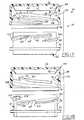
- FIGS. 14-16illustrate a closure and container package 80 in accordance with a modified embodiment of the invention.
- Package 80includes a closure 82 secured to finish 52 of container 24.
- the primary difference between package 80 in FIGS. 14-16 and package 20 in FIGS. 1-13lies in the fact that a tear band 84 is integrally molded onto the lower edge of closure peripheral skirt 86, being secured thereto by frangible bridges or a thin frangible membrane. Tear band 84 extends from the lower edge of skirt 86 to a position adjacent to bead 61 on container finish 52.
- closure 82cannot be axially compressed with respect to container finish 52 in order to remove the closure without first removing tear band 84 from the lower edge of the closure.
- Tear band 84thus provides a tamper-indicating capability to the package 80 illustrated in FIGS. 14-16.
- the tear bandalso removes top load forces from spring lip 42 to prevent damage to the spring lip under long term top load conditions.
- the remainder of package 80is the same as package 20, and identical reference numerals are employed in the drawings to indicate identical parts.
- FIGS. 17-23illustrate a container and closure package 90 in accordance with another embodiment of the invention as comprising a container 92, a closure 94 and a liner 96.
- Container 92has a cylindrical finish 98 with dual external threads 100, 102.
- Each thread 100, 102has two circumferentially spaced pockets 68 with abutment faces 66 as previously described.
- the pockets in each threadare at 90° spacing from each other, and the pockets in thread 100 are substantially diametrically opposed to the pockets in thread 102.
- Each thread 100,102preferably extends over an arc of at least 180°, plus a 10° lead-in.
- the upper end of each thread 100, 102terminates in a circumferentially facing flat abutment face 104.
- Abutment faces 104preferably lie in a common plane that intersects the central axis of the container finish.
- Closure 94 in this embodimenthas a base wall 26, a peripheral skirt 28 and a spring lip 42 as in the previous embodiments.
- Closure 94is a dual-thread closure, containing a pair of internal threads 106, 108. Each internal thread preferably extends over an arc of 190°, plus a 10° lead-in.
- Each thread 106,108includes a circumferentially spaced pair of lugs 36 with circumferentially oriented abutment surfaces 38 and sloping cam surfaces 40 as previously described. Lugs 36 are at 90° spacing.
- the upper end of each thread -i.e., the end adjacent to closure base wall 26 - terminates in an axially upwardly extending thread abutment stop 110.
- Each abutment stopprojects radially inwardly from skirt 28 and has a circumferentially facing abutment stop face 112 opposed to the stop face 38 of the adjacent lug 36 on that thread.
- abutment face 112 of stop 110cooperates with abutment face 104 at the upper end of each external thread 100,102 to prevent over-tightening of the closure onto the container and potential damage to spring element 42.
- Liner 96 in the embodiment of FIGS. 17-23is either a single-layer or multiple-layer liner that is not welded or otherwise secured to the container finish.
- Liner 96may comprise a single layer of cellulose, for example.
- liner 96is captured within closure 94 by internal threads 106, 108 adjacent to base wall 26 of the closure.
- liner 96seals against the axial edge of closure finish 98.
- FIG. 21illustrates the amount 116 of radial overlap between lugs 36 on the closure internal thread and pockets 64 on the container finish external thread.
- FIGS. 17-23has the advantage that formation of the opposing thread stops adjacent to the upper end of the closure thread helps to reduce over-torquing the closure caused by bypassing the thread stops due to ovalization.
- FIG. 24illustrates a package 120 that is similar to those previously discussed, but in which the liner has been eliminated.
- Closure 122 of package 120has a spring lip 124 that is compressed against finish 52 of container 24.
- Spring lip 124is similar to lip 42 discussed above, but is designed to achieve the desired compression of the spring lip without the liner being present. Spring lip 42 also obtains a measure of sealing against the container finish.
Landscapes
- Engineering & Computer Science (AREA)
- Mechanical Engineering (AREA)
- Closures For Containers (AREA)
- Packages (AREA)
Abstract
Description
Claims (45)
- A child-resistant closure and container package that includes:wherein said pockets in said external thread do not extend axially through saidthread such that an upper surface of said thread is continuous throughout said thread.a container having a finish with at least one external thread and pockets in saidexternal thread, anda closure having a base wall, a peripheral skirt with at least one internal thread, lugson said internal thread for receipt in said pockets, and a spring element for engagementwith said finish to bias said closure away from said finish and urge said lugs into saidpockets,one of said internal thread and said external thread having a circumferentiallyfacing axially extending stop at an end of said one thread, and the other of said internalthread and said external thread having an abutment face at an end of said other thread forabutment with said stop to prevent over-tightening of said closure on said finish and over-compressionof said spring element,
- The package set forth in claim 1 wherein said pockets and said lugs have opposedangulated surfaces to cam said lugs over said pockets during application of said closure to saidfinish, and opposed abutment surfaces to resist removal of said closure absent pressure on saidspring element.
- The package set forth in claim 1 wherein said closure, including said springelement, is of integrally molded plastic construction.
- The package set forth in claim 3 wherein said spring element comprises acircumferentially continuous conical lip that extends radially and axially inwardly from said basewall adjacent to said skirt, said lip tapering in thickness from said base wall to a free end of saidlip.
- The package set forth in claim 4 wherein said lip has a rounded free edge forengagement with said container finish.
- The package set forth in claim 5 further comprising a liner urged by said springelement into engagement with said finish.
- The package set forth in claim 6 wherein said liner includes a base with metaland plastic layers for induction sealing securement to said finish such that, upon removal of saidclosure, said metal and plastic layers remain secured to said finish and said liner base is removedwith said closure.
- The package set forth in claim 6 wherein said liner is loosely captured by saidat least one internal thread within said closure adjacent to said base wall.
- A child-resistant closure and container package that includes:a container having a finish with at least one external thread and pockets on anundersurface of said external thread that do not extend axially through said thread such that anupper surface of said external thread is continuous throughout said external thread, anda closure having a base wall, a peripheral skirt with at least one internal thread andlugs on said internal thread for receipt in said pockets, and a spring element for engagement withsaid finish to bias said closure away from said finish and urge said lugs into said pockets.
- The package as set forth in claim 9 wherein said pockets and said lugs haveopposed angulated surfaces to cam said lugs over said pockets during application of said closureto said finish, and opposed abutment surfaces to resist removal of said closure absent pressureon said spring element.
- The package set forth in claim 9 wherein one of said internal thread and saidexternal thread having a circumferentially facing axially extending stop at an end of said onethread, and the other of said internal thread and said external thread having an abutment face atan end of said other thread for abutment with said stop to prevent over-tightening of said closureon said finish and over-compression of said spring element.
- The package set forth in claim 11 wherein said stop is disposed at a lower end ofsaid at least one external thread and projects radially outwardly from said finish, and saidabutment face is disposed at a lower end of said at least one internal thread.
- The package set forth in claim 11 wherein said stop is disposed at an upper endof said at least one internal thread adjacent to said base wall and projects radially inwardly fromsaid skirt, and said abutment face is disposed at an upper end of said at least one external thread.
- The package set forth in claim 11 wherein internal and external threads arecontinuous single threads and extend for at least 360°.
- The package set forth in claim 11 wherein said internal and external threads aredouble threads, with each thread extending for at least 180°.
- The package set forth in claim 9 wherein said closure, including said springelement, is of integrally molded plastic construction.
- The package set forth in claim 16 wherein said spring element comprises acircumferentially continuous conical lip that extends radially and axially inwardly from said basewall adjacent to said skirt, said lip tapering in thickness from said base wall to a free end of saidlip.
- The package set forth in claim 17 wherein said lip has a rounded free edge forengagement with said container finish.
- The package set forth in claim 9 further comprising a liner urged by said springelement into engagement with said finish.
- The package set forth in claim 19 wherein said liner includes a base with metaland plastic layers for induction sealing securement to said finish such that, upon removal of saidclosure, said metal and plastic layers remain secured to said finish and said liner base is removedwith said closure.
- The package set forth in claim 19 wherein said liner is loosely captured by saidat least one internal thread within said closure adjacent to said base wall.
- A child-resistant closure and container package that includes:a container having a finish with at least one external thread and pockets in saidthread,a closure having a base wall, peripheral skirt with at least one internal thread andlugs on said internal thread for receipt in said pockets, and a spring element for engagement withsaid container finish to bias said closure away from said finish and urge said lugs into saidpockets, anda liner urged by said spring element into engagement with said finish, said linerincluding a base with metal and plastic layers for induction sealing securement to said finish suchthat, upon removal of said closure, said metal and plastic layers remain secured to said finish andsaid liner base is removed with said closure.
- The package set forth in claim 22 wherein said pockets in said external thread donot extend axially through said thread such that an upper surface of said thread is continuousthroughout said thread.
- The package set forth in claim 23 wherein said pockets and said lugs haveopposed angulated surfaces to cam said lugs over said pockets during application of said closureto said finish, and opposed abutment surfaces to resist removal of said closure absent pressureon said spring element.
- The package set forth in claim 11 wherein said internal and external threads aredouble threads, with each thread extending for at least 180°.
- The package set forth in claim 22 wherein said closure, including said springelement, is of integrally molded plastic construction.
- The package set forth in claim 26 wherein said spring element comprises acircumferentially continuous conical lip that extends radially and axially inwardly from said basewall adjacent to said skirt, said lip tapering in thickness from said base wall to a free end of saidlip.
- The package set forth in claim 27 wherein said lip has a rounded free edge forengagement with said liner and for engagement with said container finish when said liner isremoved after opening said package.
- The package set forth in claim 22 wherein said container is of integrally moldedplastic construction.
- The package set forth in claim 22 wherein said liner includes sequential layers ofcellulose, wax, metal and plastic, with said wax layer evaporating and said plastic layer meltingupon application of induction current to said metal layer.
- A closure that includes an integrally molded plastic body having a base wall, aperipheral skirt with at least one internal thread and lugs on an upper surface of said thread, saidlugs having an angulated surface sloping toward an end of said thread remote from said base walland a circumferentially facing radially extending abutment surface on an end of said lugs facingan opposing end of said thread, and a spring element for engagement with a container finish tobias said lugs into opposing pockets on the container finish.
- The closure set forth in claim 31 wherein said spring element comprises acircumferentially continuous conical lip that extends radially and axially inwardly from said basewall adjacent to said skirt, said lip tapering in thickness from said base wall to a free end of saidlip for differential flexing upon engagement with a container finish.
- The closure set forth in claim 32 wherein said at least one internal thread is asingle thread that extends continuously for at least 450°.
- The closure set forth in claim 32 wherein said at least one internal thread is adouble thread, with each thread extending at least 190°.
- The closure set forth in claim 31 wherein said at least one internal thread has anend remote from said base wall with a flat circumferentially facing radially extending end face.
- The closure set forth in claim 31 wherein said at least one internal thread has acircumferentially facing axially extending stop projecting radially inwardly from said skirt at anend of said thread adjacent to said base wall.
- The closure set forth in claim 31 further comprising a liner captured between saidthread and said spring element.
- The closure set forth in claim 37 wherein said liner includes sequential layers ofcellulose, wax, metal and plastic, with said wax layer evaporating and said plastic layer meltingupon application of induction current to said metal layer.
- A container that includes an integrally molded plastic body having a finish withat least one external thread and pockets on an undersurface of said thread that do not extendthrough said thread such that an upper surface of said thread is continuous throughout saidexternal thread.
- The container set forth in claim 39 wherein said pockets in said external threadhave a circumferentially extending axially angulated cam surface and a radially extendingabutment surface opposed to said cam surface.
- The container set forth in claim 39 wherein said container finish has acircumferentially facing axially extending abutment stop at a lower end of said external threadand projecting radially outwardly from said finish.
- The container set forth in claim 39 wherein said at least one external thread hasa flat circumferentially facing radially extending end face at an upper end of thread.
- The container set forth in claim 39 wherein said at least one external thread is asingle thread that extends for at least 455°.
- The container set forth in claim 39 wherein said at least one external thread is adouble thread, with each thread extending for at least 180°.
- A method of making a child-resistant closure and container package that includesthe steps of:(a) providing a container having a finish with at least one external thread andpockets in an undersurface of said thread,(b) providing a closure of one-piece integrally molded plastic constructionhaving a base wall, a peripheral skirt with at least one internal thread and lugs on an uppersurface of said internal thread, and a spring element extending axially and radially inwardly fromsaid base wall adjacent to said skirt,(c) positioning within said closure adjacent to said base wall a liner havinga base with sequential metal and plastic layers,(d) securing said closure to said container finish such that said lugs aredisposed in said pockets and said spring element urges said liner into sealing engagement withan axial end of said container finish, and then(e) securing said liner to said axial end of said container finish by inducinga current in said metal layer and melting said plastic layer onto said container finish.
Priority Applications (2)
| Application Number | Priority Date | Filing Date | Title |
|---|---|---|---|
| EP06076330AEP1710167B1 (en) | 2001-10-16 | 2002-10-16 | Child-resistant closure and container package |
| EP06076333AEP1707494A3 (en) | 2001-10-16 | 2002-10-16 | Child-resistant closure and container package |
Applications Claiming Priority (3)
| Application Number | Priority Date | Filing Date | Title |
|---|---|---|---|
| US982249 | 2001-10-16 | ||
| US09/982,249US6848590B2 (en) | 2001-10-16 | 2001-10-16 | Child-resistant closure and container package |
| EP02257189AEP1302406B1 (en) | 2001-10-16 | 2002-10-16 | Child-resistant closure and container package |
Related Parent Applications (1)
| Application Number | Title | Priority Date | Filing Date |
|---|---|---|---|
| EP02257189ADivisionEP1302406B1 (en) | 2001-10-16 | 2002-10-16 | Child-resistant closure and container package |
Related Child Applications (2)
| Application Number | Title | Priority Date | Filing Date |
|---|---|---|---|
| EP06076333ADivisionEP1707494A3 (en) | 2001-10-16 | 2002-10-16 | Child-resistant closure and container package |
| EP06076330ADivisionEP1710167B1 (en) | 2001-10-16 | 2002-10-16 | Child-resistant closure and container package |
Publications (3)
| Publication Number | Publication Date |
|---|---|
| EP1522499A2true EP1522499A2 (en) | 2005-04-13 |
| EP1522499A3 EP1522499A3 (en) | 2005-08-03 |
| EP1522499B1 EP1522499B1 (en) | 2007-11-28 |
Family
ID=25528982
Family Applications (4)
| Application Number | Title | Priority Date | Filing Date |
|---|---|---|---|
| EP06076330AExpired - LifetimeEP1710167B1 (en) | 2001-10-16 | 2002-10-16 | Child-resistant closure and container package |
| EP04078578AExpired - LifetimeEP1522499B1 (en) | 2001-10-16 | 2002-10-16 | Child-resistant closure and container package |
| EP02257189AExpired - LifetimeEP1302406B1 (en) | 2001-10-16 | 2002-10-16 | Child-resistant closure and container package |
| EP06076333AWithdrawnEP1707494A3 (en) | 2001-10-16 | 2002-10-16 | Child-resistant closure and container package |
Family Applications Before (1)
| Application Number | Title | Priority Date | Filing Date |
|---|---|---|---|
| EP06076330AExpired - LifetimeEP1710167B1 (en) | 2001-10-16 | 2002-10-16 | Child-resistant closure and container package |
Family Applications After (2)
| Application Number | Title | Priority Date | Filing Date |
|---|---|---|---|
| EP02257189AExpired - LifetimeEP1302406B1 (en) | 2001-10-16 | 2002-10-16 | Child-resistant closure and container package |
| EP06076333AWithdrawnEP1707494A3 (en) | 2001-10-16 | 2002-10-16 | Child-resistant closure and container package |
Country Status (13)
| Country | Link |
|---|---|
| US (2) | US6848590B2 (en) |
| EP (4) | EP1710167B1 (en) |
| JP (1) | JP2003285852A (en) |
| CN (1) | CN1420065A (en) |
| BR (1) | BRPI0205918B1 (en) |
| CA (1) | CA2408064C (en) |
| DE (3) | DE60216215T2 (en) |
| HU (1) | HUP0203498A3 (en) |
| MX (1) | MXPA02010228A (en) |
| NZ (1) | NZ522004A (en) |
| PL (1) | PL356678A1 (en) |
| SG (1) | SG126707A1 (en) |
| TW (1) | TWI224070B (en) |
Families Citing this family (58)
| Publication number | Priority date | Publication date | Assignee | Title |
|---|---|---|---|---|
| US7168581B2 (en)* | 2001-12-21 | 2007-01-30 | Rexam Medical Packaging Inc. | Closure for a retort processed container having a peelable seal |
| GR1004079B (en)* | 2002-01-16 | 2002-11-29 | Circumferential malformed compression ring for sealing plastic closures | |
| US7083058B2 (en)* | 2003-01-31 | 2006-08-01 | Abbott Laboratories | Linerless sealing closure for a container |
| US7644902B1 (en) | 2003-05-31 | 2010-01-12 | Rexam Medical Packaging Inc. | Apparatus for producing a retort thermal processed container with a peelable seal |
| US7527160B2 (en)* | 2003-10-09 | 2009-05-05 | Rexam Prescription Products Inc. | Closure having user-modifiable functionality |
| US7055708B1 (en)* | 2003-10-09 | 2006-06-06 | Owens-Illinois Prescription Products Inc. | Child-resistant package |
| US7819264B2 (en) | 2003-12-03 | 2010-10-26 | Rexam Closure Systems Inc. | Child-resistant closure, container and package |
| US7527159B2 (en) | 2004-03-11 | 2009-05-05 | Rexam Closure Systems Inc. | Threaded child-resistant package having linerless closure |
| WO2005056416A1 (en)* | 2003-12-03 | 2005-06-23 | Owens-Illinois Closure Inc. | Child-resistant closure, container and package |
| US7331479B2 (en)* | 2004-04-29 | 2008-02-19 | Rexam Delta Inc. | Child resistant container and cap |
| MXPA06014813A (en)* | 2004-06-23 | 2007-04-25 | Obrist Closures Switzerland | Wadless closure. |
| US7798359B1 (en) | 2004-08-17 | 2010-09-21 | Momar Industries LLC | Heat-sealed, peelable lidding membrane for retort packaging |
| US7434703B2 (en)* | 2004-09-27 | 2008-10-14 | Rexam Prescription Products Inc. | Child-resistant tamper-indicating package |
| US20060068193A1 (en)* | 2004-09-29 | 2006-03-30 | Lear Corporation | Method and apparatus for making a trim panel with a self-skinning blown elastomer component |
| US7458631B2 (en) | 2004-10-19 | 2008-12-02 | International Automotive Components Group North America, Inc. | Automotive armrest with soft feel and method of making the same |
| US7156437B2 (en) | 2004-10-19 | 2007-01-02 | Lear Corporation | Automotive trim part with applique and method of making same |
| US20060082179A1 (en)* | 2004-10-19 | 2006-04-20 | Depue Todd L | Automotive trim assembly having impact countermeasures and method of making the same |
| US7478854B2 (en) | 2004-10-19 | 2009-01-20 | International Automotive Components Group North America, Inc. | Automotive handle with soft feel and method of making the same |
| US7458604B2 (en) | 2004-10-20 | 2008-12-02 | International Automotive Components Group North America, Inc. | Automotive trim assembly having an integrated airbag door |
| US7192074B2 (en)* | 2004-11-10 | 2007-03-20 | Lear Corporation | Automotive compartment having an integrated spring mechanism and method of making the same |
| US7703617B1 (en) | 2004-11-19 | 2010-04-27 | Rexam Closures And Containers, Inc. | Bayonet closure container combination with angled bayonet lugs |
| US20060163192A1 (en)* | 2005-01-14 | 2006-07-27 | Price Michael L | Linerless plastic closure |
| DK1890944T3 (en) | 2005-06-10 | 2011-07-04 | Nis Buchwaldt-Nissen | Sealing between outer and inner lids |
| US7469794B2 (en)* | 2005-06-16 | 2008-12-30 | David Krueger | Child resistant container-closure assembly |
| US8100277B1 (en) | 2005-07-14 | 2012-01-24 | Rexam Closures And Containers Inc. | Peelable seal for an opening in a container neck |
| US7780024B1 (en) | 2005-07-14 | 2010-08-24 | Rexam Closures And Containers Inc. | Self peel flick-it seal for an opening in a container neck |
| US7832577B2 (en)* | 2005-07-26 | 2010-11-16 | Rexam Prescription Products Inc. | Child-resistant closure and package convertible to non-child-resistant operation |
| US20070034595A1 (en)* | 2005-08-10 | 2007-02-15 | Continental Afa Dispensing Company | Bottle and cap closure apparatus with torque feature |
| US20070132208A1 (en)* | 2005-12-12 | 2007-06-14 | Winter David C | Trailer |
| US7388506B2 (en)* | 2006-02-07 | 2008-06-17 | Rexam Healthcare Packaging Inc. | Closure and package with induction seal and RFID tag |
| US7819265B2 (en)* | 2006-06-06 | 2010-10-26 | Rexam Closure Systems Inc. | Child-resistant closure and container package |
| USD645349S1 (en) | 2006-06-07 | 2011-09-20 | Kraft Foods Global Brands Llc | Container |
| US7621413B2 (en)* | 2006-06-09 | 2009-11-24 | Seaquist Closures Foreign, Inc. | Closure system with orientation and removal capability |
| DE102006040888B3 (en)* | 2006-08-31 | 2007-11-08 | Lts Lohmann Therapie-Systeme Ag | Container closure system for storing e.g. medicine, has cap form-fittingly holding closure element on container in area of opening to be closed by locking element provided at container, where closure element lies on front surface |
| US20080110850A1 (en)* | 2006-11-14 | 2008-05-15 | Andrew Thomas Tilton | Audible closing feature for a threaded container and lid |
| US20080142468A1 (en)* | 2006-12-15 | 2008-06-19 | Owens-Illinois Healthcare Packaging Inc. | Dual-action child-resistant package and child-resistant closure for such a package |
| US8056744B2 (en)* | 2007-01-12 | 2011-11-15 | Phoenix Closures, Inc. | Closure with ring ribs |
| US8113367B2 (en)* | 2007-02-20 | 2012-02-14 | Con Agra Foods RDM, Inc. | Non-removable closure having a dispensing aperture extending therethrough |
| US8584876B2 (en)* | 2007-07-05 | 2013-11-19 | Kraft Foods Group Brands Llc | Food containers adapted for accommodating pressure changes using skip seals and methods of manufacture |
| US8251236B1 (en) | 2007-11-02 | 2012-08-28 | Berry Plastics Corporation | Closure with lifting mechanism |
| US8079483B2 (en)* | 2008-09-11 | 2011-12-20 | Rexam Healthcare Packaging Inc. | Closure with stopping mechanism |
| US8123058B2 (en) | 2008-09-11 | 2012-02-28 | Rexam Healthcare Packaging Inc. | Closure with stopping mechanism |
| US8316622B2 (en)* | 2009-06-10 | 2012-11-27 | Shriji Polymers India Limited | Child-resistant cap |
| JP5486753B2 (en)* | 2009-11-30 | 2014-05-07 | 日本テトラパック株式会社 | Packaging container manufacturing method, spout stopper and packaging container |
| DE102011084308A1 (en)* | 2010-12-08 | 2012-06-14 | Continental Teves Ag & Co. Ohg | Expansion tank for hydraulic motor vehicle brake systems |
| GB201402604D0 (en)* | 2014-02-14 | 2014-04-02 | Obrist Closures Switzerland | Closure combination |
| CN104939483A (en)* | 2015-06-02 | 2015-09-30 | 义乌市美密实业有限公司 | Anti-liquid leakage cosmetic container |
| WO2018031593A1 (en)* | 2016-08-08 | 2018-02-15 | Juul Labs, Inc. | Storage containers for vaporizer cartridges |
| US20200087041A1 (en)* | 2016-12-22 | 2020-03-19 | Cng Co., Ltd. | Compressed gas supply device |
| GB201702408D0 (en)* | 2017-02-14 | 2017-03-29 | Norton (Waterford) Ltd | Inhalers and related methods |
| WO2019104043A1 (en)* | 2017-11-21 | 2019-05-31 | Drug Platics & Glass Company, Inc. | Child-resistant single wall squeeze and turn closure and container assembly |
| GB201803224D0 (en)* | 2018-02-27 | 2018-04-11 | Compgen Ltd | A container with child resistant means |
| GB201809831D0 (en)* | 2018-06-15 | 2018-08-01 | Douwe Egberts Bv | Container lids and methods of manufacturing the same |
| AR116722A1 (en) | 2018-10-08 | 2021-06-09 | Juul Labs Inc | ASSEMBLY OF CHARGE ADAPTER OF A VAPORIZER |
| USD1014251S1 (en) | 2019-06-03 | 2024-02-13 | Berlin Packaging, Llc | Tamper evident closure assembly |
| USD1023755S1 (en) | 2019-06-03 | 2024-04-23 | Berlin Packaging, Llc | Tamper evident closure assembly |
| US11224311B2 (en) | 2019-10-01 | 2022-01-18 | David Aryanpanah | Grinder safety cap |
| US12376704B1 (en)* | 2024-07-11 | 2025-08-05 | Bar Products.Com, Inc. | Multifunctional portable grinder with integrated lighter holder and retractable mechanism |
Family Cites Families (35)
| Publication number | Priority date | Publication date | Assignee | Title |
|---|---|---|---|---|
| US3880313A (en) | 1968-03-04 | 1975-04-29 | Edward G Akers | Safety cap and container |
| US3917096A (en) | 1968-03-22 | 1975-11-04 | Reflex Corp Of Canada Limited | Safety package |
| US3739933A (en) | 1971-03-22 | 1973-06-19 | B Degaetano | Liquid-proof safety closure |
| US3741421A (en)* | 1971-05-10 | 1973-06-26 | J Wittwer | Safety locking cap |
| US3888376A (en)* | 1974-06-13 | 1975-06-10 | Cwc Ind | Safety closure cap for containers |
| US3907145A (en) | 1974-08-05 | 1975-09-23 | William Horvath | Safety container including snap-on cap |
| US4091948A (en) | 1976-03-15 | 1978-05-30 | Northup John D | Linerless container closure |
| AU2174377A (en)* | 1976-03-18 | 1978-08-03 | Marini S | Childproof top for poison containers |
| DE2625875A1 (en) | 1976-06-09 | 1977-12-22 | Cwc Ind | Childproof safety closure for container - has locking projection on cap thread and corresponding recess on thread of container neck |
| AU2575077A (en) | 1976-06-10 | 1978-12-07 | Cooper M F A | Child resistant closure |
| US4032028A (en) | 1976-09-13 | 1977-06-28 | Apl Corporation | Safety cap |
| US4053077A (en)* | 1976-10-19 | 1977-10-11 | Defelice Amedio | Child safety cap |
| US4084717A (en) | 1977-06-29 | 1978-04-18 | Vca Corporation | Container and closure |
| US4090629A (en) | 1977-08-22 | 1978-05-23 | International Tools (1973) Limited | Spiral lock safety closure |
| US4139112A (en) | 1977-10-31 | 1979-02-13 | Cooke Carl W | Safety closure cap |
| CA1167413A (en)* | 1980-06-19 | 1984-05-15 | Lawrence E. Wiles | Child resistant container cover |
| US4387817A (en) | 1980-06-19 | 1983-06-14 | Ethyl Products Company | Child resistant container cover |
| US4353475A (en) | 1981-06-11 | 1982-10-12 | Gibson Associates Inc. | Safety closure device |
| US4375858A (en) | 1981-11-02 | 1983-03-08 | American Cyanamid Company | Child resistant closure device |
| DK147510C (en) | 1982-07-01 | 1985-03-04 | Johannes Saemundur Palsson | SAFETY CLOSES WITH A CLOSURE COVER WHICH CAN BE INSERTED ON A CONTAINER PART THAT HAS A CLOSING ORGANIZATION FOR THE CLOSE COVER |
| US4522307A (en) | 1983-10-19 | 1985-06-11 | Anchor Hocking Corporation | Child-resistant tamper-evident closure |
| EP0147951B1 (en) | 1983-12-01 | 1988-09-07 | Johnsen & Jorgensen (Plastics) Limited | A child resistant and tamper-resistant container and closure assembly |
| US4531649A (en)* | 1984-04-23 | 1985-07-30 | Anchor Hocking Corporation | Molded plastic cap with sealing liner |
| US4620640A (en)* | 1985-12-16 | 1986-11-04 | Owens-Illinois, Inc. | Lined child-resistant closure for widemouth liquid container |
| US4822326A (en)* | 1987-08-20 | 1989-04-18 | Boardman Molded Products, Inc. | Method of forming a tamper evident sealing liner |
| US4935273A (en)* | 1989-02-01 | 1990-06-19 | Minnesota Mining And Manufacturing Company | Pressure-activated innerseals and containers using same |
| US5135124A (en) | 1991-05-09 | 1992-08-04 | Hoover Universal, Inc. | Pressure lock bayonet closure |
| US5449078A (en) | 1994-07-08 | 1995-09-12 | Thermar Corporation | Combination of a container and a safety cap therefor |
| US5462186A (en) | 1994-08-02 | 1995-10-31 | The Coca Cola Company | Cam follower closure on container with cam track finish |
| US5712042A (en)* | 1995-04-17 | 1998-01-27 | Kerr Group Inc. | Second seal for closure liners |
| DE69622745T2 (en) | 1995-12-08 | 2002-11-28 | Beeson And Sons Ltd., Rickmansworth | CONTAINER LOCKING ARRANGEMENT WITH PROFILED SCREW THREADS |
| US5819967A (en) | 1996-06-12 | 1998-10-13 | Pfizer Inc. | Child-resistant, senior friendly container |
| GB2319513A (en)* | 1996-11-21 | 1998-05-27 | Able Ind Ltd | Container and closure with safety threads |
| US5938055A (en) | 1997-03-12 | 1999-08-17 | Philips; Terry | Safety cap and container |
| US6174274B1 (en)* | 1997-10-08 | 2001-01-16 | Rexam Plastics, Inc. | Method and apparatus for creating preformed bonded pull tabs over a reseal liner |
- 2001
- 2001-10-16USUS09/982,249patent/US6848590B2/ennot_activeExpired - Lifetime
- 2002
- 2002-10-15CACA002408064Apatent/CA2408064C/ennot_activeExpired - Fee Related
- 2002-10-16MXMXPA02010228Apatent/MXPA02010228A/enactiveIP Right Grant
- 2002-10-16EPEP06076330Apatent/EP1710167B1/ennot_activeExpired - Lifetime
- 2002-10-16DEDE60216215Tpatent/DE60216215T2/ennot_activeExpired - Lifetime
- 2002-10-16SGSG200206330Apatent/SG126707A1/enunknown
- 2002-10-16CNCN02155806.XApatent/CN1420065A/enactivePending
- 2002-10-16TWTW091123812Apatent/TWI224070B/enactive
- 2002-10-16DEDE60230078Tpatent/DE60230078D1/ennot_activeExpired - Lifetime
- 2002-10-16EPEP04078578Apatent/EP1522499B1/ennot_activeExpired - Lifetime
- 2002-10-16EPEP02257189Apatent/EP1302406B1/ennot_activeExpired - Lifetime
- 2002-10-16BRBRPI0205918Apatent/BRPI0205918B1/ennot_activeIP Right Cessation
- 2002-10-16NZNZ522004Apatent/NZ522004A/enunknown
- 2002-10-16DEDE60223852Tpatent/DE60223852T2/ennot_activeExpired - Lifetime
- 2002-10-16PLPL02356678Apatent/PL356678A1/ennot_activeApplication Discontinuation
- 2002-10-16HUHU0203498Apatent/HUP0203498A3/enunknown
- 2002-10-16EPEP06076333Apatent/EP1707494A3/ennot_activeWithdrawn
- 2002-10-16JPJP2002337290Apatent/JP2003285852A/enactivePending
- 2004
- 2004-11-04USUS10/981,224patent/US20050055986A1/ennot_activeAbandoned
Also Published As
| Publication number | Publication date |
|---|---|
| EP1707494A2 (en) | 2006-10-04 |
| EP1302406B1 (en) | 2006-11-22 |
| EP1302406A2 (en) | 2003-04-16 |
| DE60223852T2 (en) | 2008-10-09 |
| MXPA02010228A (en) | 2004-12-13 |
| EP1710167B1 (en) | 2008-11-26 |
| EP1522499B1 (en) | 2007-11-28 |
| CN1420065A (en) | 2003-05-28 |
| JP2003285852A (en) | 2003-10-07 |
| DE60223852D1 (en) | 2008-01-10 |
| EP1710167A2 (en) | 2006-10-11 |
| TWI224070B (en) | 2004-11-21 |
| BR0205918A (en) | 2003-07-22 |
| EP1522499A3 (en) | 2005-08-03 |
| DE60230078D1 (en) | 2009-01-08 |
| HUP0203498A2 (en) | 2003-06-28 |
| HU0203498D0 (en) | 2002-12-28 |
| US20030121877A1 (en) | 2003-07-03 |
| SG126707A1 (en) | 2006-11-29 |
| EP1710167A3 (en) | 2007-02-28 |
| US6848590B2 (en) | 2005-02-01 |
| PL356678A1 (en) | 2003-04-22 |
| BRPI0205918B1 (en) | 2017-03-28 |
| HUP0203498A3 (en) | 2004-04-28 |
| DE60216215T2 (en) | 2007-10-04 |
| CA2408064C (en) | 2008-01-29 |
| US20050055986A1 (en) | 2005-03-17 |
| DE60216215D1 (en) | 2007-01-04 |
| NZ522004A (en) | 2003-11-28 |
| CA2408064A1 (en) | 2003-04-16 |
| EP1707494A3 (en) | 2007-02-28 |
| EP1302406A3 (en) | 2003-08-13 |
Similar Documents
| Publication | Publication Date | Title |
|---|---|---|
| EP1710167B1 (en) | Child-resistant closure and container package | |
| US7637384B2 (en) | Tamper evident closure with locking band and container therefor | |
| US7182213B2 (en) | Closure assembly for a wide mouth vessel | |
| US7975864B2 (en) | Linerless bore seal closure | |
| US5004112A (en) | Tamper-indicating plastic closure | |
| US4402418A (en) | Tamperproof closure | |
| US7004341B2 (en) | Tamper evident composite closure with threadless securement | |
| US5950849A (en) | Container closure with ribbed enlarged grasping region | |
| GB2033350A (en) | Tamperproof closure | |
| AU2006314241A1 (en) | Jaw seals for container closure assemblies | |
| US20050077264A1 (en) | Container with a security closure | |
| US6381928B1 (en) | Tamper-indicating closure and container package | |
| GB2407561A (en) | Linerless bore seal |
Legal Events
| Date | Code | Title | Description |
|---|---|---|---|
| PUAI | Public reference made under article 153(3) epc to a published international application that has entered the european phase | Free format text:ORIGINAL CODE: 0009012 | |
| AC | Divisional application: reference to earlier application | Ref document number:1302406 Country of ref document:EP Kind code of ref document:P | |
| AK | Designated contracting states | Kind code of ref document:A2 Designated state(s):DE FR GB IT | |
| PUAL | Search report despatched | Free format text:ORIGINAL CODE: 0009013 | |
| AK | Designated contracting states | Kind code of ref document:A3 Designated state(s):DE FR GB IT | |
| 17P | Request for examination filed | Effective date:20060118 | |
| AKX | Designation fees paid | Designated state(s):DE FR GB IT | |
| 17Q | First examination report despatched | Effective date:20060511 | |
| RAP1 | Party data changed (applicant data changed or rights of an application transferred) | Owner name:OWENS-ILLINOIS CLOSURE, INC. | |
| RAP3 | Party data changed (applicant data changed or rights of an application transferred) | Owner name:OWENS-ILLINOIS CLOSURE, INC. | |
| GRAP | Despatch of communication of intention to grant a patent | Free format text:ORIGINAL CODE: EPIDOSNIGR1 | |
| GRAS | Grant fee paid | Free format text:ORIGINAL CODE: EPIDOSNIGR3 | |
| GRAA | (expected) grant | Free format text:ORIGINAL CODE: 0009210 | |
| AC | Divisional application: reference to earlier application | Ref document number:1302406 Country of ref document:EP Kind code of ref document:P | |
| AK | Designated contracting states | Kind code of ref document:B1 Designated state(s):DE FR GB IT | |
| REG | Reference to a national code | Ref country code:GB Ref legal event code:FG4D | |
| REF | Corresponds to: | Ref document number:60223852 Country of ref document:DE Date of ref document:20080110 Kind code of ref document:P | |
| RAP2 | Party data changed (patent owner data changed or rights of a patent transferred) | Owner name:REXAM CLOSURE SYSTEMS INC. | |
| ET | Fr: translation filed | ||
| PLBE | No opposition filed within time limit | Free format text:ORIGINAL CODE: 0009261 | |
| STAA | Information on the status of an ep patent application or granted ep patent | Free format text:STATUS: NO OPPOSITION FILED WITHIN TIME LIMIT | |
| 26N | No opposition filed | Effective date:20080829 | |
| PGFP | Annual fee paid to national office [announced via postgrant information from national office to epo] | Ref country code:IT Payment date:20091017 Year of fee payment:8 | |
| PG25 | Lapsed in a contracting state [announced via postgrant information from national office to epo] | Ref country code:IT Free format text:LAPSE BECAUSE OF NON-PAYMENT OF DUE FEES Effective date:20101016 | |
| REG | Reference to a national code | Ref country code:FR Ref legal event code:PLFP Year of fee payment:14 | |
| REG | Reference to a national code | Ref country code:FR Ref legal event code:PLFP Year of fee payment:15 | |
| REG | Reference to a national code | Ref country code:FR Ref legal event code:PLFP Year of fee payment:16 | |
| PGFP | Annual fee paid to national office [announced via postgrant information from national office to epo] | Ref country code:FR Payment date:20171025 Year of fee payment:16 Ref country code:DE Payment date:20171027 Year of fee payment:16 | |
| PGFP | Annual fee paid to national office [announced via postgrant information from national office to epo] | Ref country code:GB Payment date:20171027 Year of fee payment:16 | |
| REG | Reference to a national code | Ref country code:DE Ref legal event code:R119 Ref document number:60223852 Country of ref document:DE | |
| GBPC | Gb: european patent ceased through non-payment of renewal fee | Effective date:20181016 | |
| PG25 | Lapsed in a contracting state [announced via postgrant information from national office to epo] | Ref country code:DE Free format text:LAPSE BECAUSE OF NON-PAYMENT OF DUE FEES Effective date:20190501 | |
| PG25 | Lapsed in a contracting state [announced via postgrant information from national office to epo] | Ref country code:FR Free format text:LAPSE BECAUSE OF NON-PAYMENT OF DUE FEES Effective date:20181031 | |
| PG25 | Lapsed in a contracting state [announced via postgrant information from national office to epo] | Ref country code:GB Free format text:LAPSE BECAUSE OF NON-PAYMENT OF DUE FEES Effective date:20181016 |