EP1522130B1 - Optical cable installation with cable lubricator - Google Patents
Optical cable installation with cable lubricatorDownload PDFInfo
- Publication number
- EP1522130B1 EP1522130B1EP03764081.0AEP03764081AEP1522130B1EP 1522130 B1EP1522130 B1EP 1522130B1EP 03764081 AEP03764081 AEP 03764081AEP 1522130 B1EP1522130 B1EP 1522130B1
- Authority
- EP
- European Patent Office
- Prior art keywords
- cable
- duct
- lubricator
- lubrication
- compartment
- Prior art date
- Legal status (The legal status is an assumption and is not a legal conclusion. Google has not performed a legal analysis and makes no representation as to the accuracy of the status listed.)
- Expired - Lifetime
Links
- 238000009434installationMethods0.000titledescription14
- 230000003287optical effectEffects0.000titledescription3
- 238000005461lubricationMethods0.000claimsdescription73
- 239000000314lubricantSubstances0.000claimsdescription56
- 238000007664blowingMethods0.000claimsdescription49
- 238000000034methodMethods0.000claimsdescription24
- 239000000463materialSubstances0.000claimsdescription23
- 230000001681protective effectEffects0.000claimsdescription20
- 239000012530fluidSubstances0.000claimsdescription16
- 239000000835fiberSubstances0.000claimsdescription12
- 238000004891communicationMethods0.000claimsdescription7
- 238000007789sealingMethods0.000claimsdescription4
- 239000002984plastic foamSubstances0.000claimsdescription3
- 238000011144upstream manufacturingMethods0.000claims1
- 238000009736wettingMethods0.000claims1
- 239000006260foamSubstances0.000description20
- 230000001050lubricating effectEffects0.000description12
- 238000002347injectionMethods0.000description9
- 239000007924injectionSubstances0.000description9
- 238000010168coupling processMethods0.000description6
- 238000005859coupling reactionMethods0.000description6
- 230000006872improvementEffects0.000description5
- 239000013307optical fiberSubstances0.000description5
- -1e.g.Substances0.000description4
- 229920001903high density polyethylenePolymers0.000description4
- 239000004700high-density polyethyleneSubstances0.000description4
- 239000004698PolyethyleneSubstances0.000description3
- 229920005830Polyurethane FoamPolymers0.000description3
- 229910000831SteelInorganic materials0.000description3
- 238000003780insertionMethods0.000description3
- 230000037431insertionEffects0.000description3
- 229920000573polyethylenePolymers0.000description3
- 239000011496polyurethane foamSubstances0.000description3
- 239000010959steelSubstances0.000description3
- 238000012360testing methodMethods0.000description3
- RYGMFSIKBFXOCR-UHFFFAOYSA-NCopperChemical compound[Cu]RYGMFSIKBFXOCR-UHFFFAOYSA-N0.000description2
- 239000004677NylonSubstances0.000description2
- 239000000443aerosolSubstances0.000description2
- 230000008878couplingEffects0.000description2
- 238000013016dampingMethods0.000description2
- 238000010586diagramMethods0.000description2
- 230000000694effectsEffects0.000description2
- 238000007373indentationMethods0.000description2
- 239000002184metalSubstances0.000description2
- 229910052751metalInorganic materials0.000description2
- 239000000203mixtureSubstances0.000description2
- 229920001778nylonPolymers0.000description2
- 229920003023plasticPolymers0.000description2
- 239000004033plasticSubstances0.000description2
- 229920000642polymerPolymers0.000description2
- 229920006395saturated elastomerPolymers0.000description2
- 230000002195synergetic effectEffects0.000description2
- 239000010409thin filmSubstances0.000description2
- XLYOFNOQVPJJNP-UHFFFAOYSA-NwaterSubstancesOXLYOFNOQVPJJNP-UHFFFAOYSA-N0.000description2
- 238000004078waterproofingMethods0.000description2
- 229910001369BrassInorganic materials0.000description1
- 239000005662Paraffin oilSubstances0.000description1
- 239000004721Polyphenylene oxideSubstances0.000description1
- 230000002745absorbentEffects0.000description1
- 239000002250absorbentSubstances0.000description1
- 230000009471actionEffects0.000description1
- 239000004760aramidSubstances0.000description1
- 229920003235aromatic polyamidePolymers0.000description1
- SVPXDRXYRYOSEX-UHFFFAOYSA-NbentoquatamChemical compoundO.O=[Si]=O.O=[Al]O[Al]=OSVPXDRXYRYOSEX-UHFFFAOYSA-N0.000description1
- 239000010951brassSubstances0.000description1
- 230000001413cellular effectEffects0.000description1
- 230000006835compressionEffects0.000description1
- 238000007906compressionMethods0.000description1
- 238000007796conventional methodMethods0.000description1
- 229910052802copperInorganic materials0.000description1
- 239000010949copperSubstances0.000description1
- 238000011161developmentMethods0.000description1
- 238000001035dryingMethods0.000description1
- 239000000839emulsionSubstances0.000description1
- 238000002474experimental methodMethods0.000description1
- 238000001125extrusionMethods0.000description1
- 239000002783friction materialSubstances0.000description1
- 229920000126latexPolymers0.000description1
- 239000006210lotionSubstances0.000description1
- 239000011159matrix materialSubstances0.000description1
- 210000002445nippleAnatomy0.000description1
- 238000005192partitionMethods0.000description1
- JTJMJGYZQZDUJJ-UHFFFAOYSA-NphencyclidineChemical compoundC1CCCCN1C1(C=2C=CC=CC=2)CCCCC1JTJMJGYZQZDUJJ-UHFFFAOYSA-N0.000description1
- 229920000728polyesterPolymers0.000description1
- 229920000570polyetherPolymers0.000description1
- 229920001296polysiloxanePolymers0.000description1
- 230000002028prematureEffects0.000description1
- 230000008569processEffects0.000description1
- 230000009467reductionEffects0.000description1
- 239000000243solutionSubstances0.000description1
- 125000006850spacer groupChemical group0.000description1
- 238000010998test methodMethods0.000description1
- 238000012546transferMethods0.000description1
- 229920002554vinyl polymerPolymers0.000description1
- 238000004804windingMethods0.000description1
Images


Classifications
- G—PHYSICS
- G02—OPTICS
- G02B—OPTICAL ELEMENTS, SYSTEMS OR APPARATUS
- G02B6/00—Light guides; Structural details of arrangements comprising light guides and other optical elements, e.g. couplings
- G02B6/46—Processes or apparatus adapted for installing or repairing optical fibres or optical cables
- G02B6/50—Underground or underwater installation; Installation through tubing, conduits or ducts
- G02B6/52—Underground or underwater installation; Installation through tubing, conduits or ducts using fluid, e.g. air
- H—ELECTRICITY
- H02—GENERATION; CONVERSION OR DISTRIBUTION OF ELECTRIC POWER
- H02G—INSTALLATION OF ELECTRIC CABLES OR LINES, OR OF COMBINED OPTICAL AND ELECTRIC CABLES OR LINES
- H02G1/00—Methods or apparatus specially adapted for installing, maintaining, repairing or dismantling electric cables or lines
- H02G1/06—Methods or apparatus specially adapted for installing, maintaining, repairing or dismantling electric cables or lines for laying cables, e.g. laying apparatus on vehicle
- H02G1/08—Methods or apparatus specially adapted for installing, maintaining, repairing or dismantling electric cables or lines for laying cables, e.g. laying apparatus on vehicle through tubing or conduit, e.g. rod or draw wire for pushing or pulling
- H02G1/086—Methods or apparatus specially adapted for installing, maintaining, repairing or dismantling electric cables or lines for laying cables, e.g. laying apparatus on vehicle through tubing or conduit, e.g. rod or draw wire for pushing or pulling using fluid as pulling means, e.g. liquid, pressurised gas or suction means
Definitions
- This inventionrelates to a method and apparatus for installing a cable in a duct, according to the preamble of claims 1 and 11, respectively.
- Protective cable ductshave been channelized in an effort to satisfy these concerns.
- one or more guide tubeswhose interior may have a lower coefficient of friction than the existing duct, are installed in the existing protective duct, thereby establishing separate channels in which cable, optionally at a later time, can be pulled through the protective duct over a greater length.
- cables with only a little play in the ductcan be installed over long distances.
- stiffness of the cablecontributes more to the friction when passing bends and windings (undulations) in the duct trajectory, pushing becomes more efficient because the cable has less play to develop buckling. Even so, frictional effects have limited the installation lengths attainable by pushing and blowing techniques. Improvements in cable lubrication have been made to overcome those frictional limitations.
- JP 2001 309519 Arefers to a method to lubricate a cable.
- the lubricantis also wiped over the cable, but this is done outside the pressurised space, just after the mechanical feeding.
- US-A-6 116 578discloses an apparatus wherein foam is blown into an installation duct. This foam adheres to the cable due to expansion and does not serve to lubricate, but to pick up extra drag forces from the airflow.
- FR-A-2 655 783does refer to a method to lubricate a cable. But the lubricant is not present in a pressurised space. Also the lubricant is not wiped over the cable but spread over the cable by a sonic shockwave (Venturi), supposed to create a local vacuum.
- Venturisonic shockwave
- the apparatus according to the inventionis characterized in that the pushing means are arranged in the launching apparatus; that the cable lubricator is connected in an operative position between the launching apparatus and the duct, and that the lubrication passage is adapted to convey pressurized air from the launch apparatus into the duct.
- the cable lubricatoris characterized in that the first connector is adapted to receive, together with the cable, pressurized air through a first guide tube and that the second connector is adapted to be connected to a second guide tube and that the lubrication passage is adapted to convey pressurized air from the first guide tube to the second guide tube.
- the present inventionconsists of a serially connected lubricator with foam-plugs and suitable lubricant, installed in the protective duct downstream of pushing/blowing cable launching equipment.
- the lubricatoroperates under pressure and the airflow, needed to blow the cable, is bypassed into the duct.
- Guide blocks to avoid buckling of the cable when pushed through the relatively large lubricating chamberare provided. The latter is especially important for smaller diameter cable with less stiffness.
- the lubricatorincludes a lubrication compartment that is pressurized with airflow from the launching apparatus.
- the foam plugs, saturated with a viscous lubricant,are placed in the compartment for contacting the cable.
- lubricantis wiped onto the cable as the cable moves in contact with the foam plugs.
- FIGURE 1A portion of a typical underground fiber optic conduit network is schematically shown in FIGURE 1 .
- the networkincludes a longitudinally extending trajectory duct 10 or conduit, typically made of a sturdy plastic material, e.g. , 3.175 cm (1.25 inches), 3.81 cm (1.5 inches) or 5.08 cm (2.0 inches) in diameter.
- the conduit 10is buried in the ground 12 and is carrying small diameter guide tubes in which fiber optic cables are to be installed.
- the conduit 10 and its cablestypically extend several thousand meters, and a launching station, such as at a hand-hole 14, is located at a predetermined central location.
- guide-tubes 16, 18, 20,22 and 24extend out of the protective duct 10 (see also FIGURE 2 ).
- blowing/pushing equipmentcan be used in tandem operation. End caps 26 seal off the guide tubes 20, 22, 24 where no cables have been installed.
- a cable launching unit 28is set up adjacent the hand-hole 14, in conjunction with a cable straightener unit 30, to introduce a fiber optic cable 32 into one of the guide tubes.
- a supply of new fiber optic cableusually consisting of thousands of meters, is coiled or wound on a reel 34 positioned above ground. The cable 32 is unwound from the reel and is fed into the cable-straightening unit 30.
- the cableis fed into the cable launching unit 28, for example, a combination pushing and blowing cable insertion equipment of the type sold by Sherman & Reilly, Inc. of Chattanooga, Tennessee, or as shown in U.S. Patent 4,850,569 , to which reference is made for whatever details described therein as may be necessary for the full understanding of the operation of the pushing and blowing unit.
- a combination pushing and blowing cable insertion equipmentof the type sold by Sherman & Reilly, Inc. of Chattanooga, Tennessee, or as shown in U.S. Patent 4,850,569 , to which reference is made for whatever details described therein as may be necessary for the full understanding of the operation of the pushing and blowing unit.
- the cable 32coming from the straightener 30, is to be inserted into the underground guide tube 18. This is done with the synergetic blowing and pushing action of the insertion unit 28.
- the cable 32is pushed by means of a mechanically (electric or pneumatic) driven wheel 36 that has an outer layer of machined hard metal with a groove for engaging the cable.
- a second (not mechanically driven) idler wheel 38is pushed against the drive wheel 36. Pushing of the wheel 38, which can pivot on arm 40, is done via spring 42 by turning around the adjustment wheel 44 to control the pushing force of the drive wheel 38.
- the cable 32enters the housing 34 via a conical feed-through 46 that is cut to fit exactly the cable size.
- This feed-throughis mounted on a splittable cylindrical entrance duct 48 that makes an airtight seal when the housing is closed.
- the guidetube 18is received in a splittable, cylindrical exit duct 49 also making airtight sealing.
- the guide tube 18extends into the housing 34 until almost touching the wheels, to avoid buckling.
- the guide tube 18can be mounted using a push/pull connector 50.
- Airis fed using a connection 52 via valve 54.
- the sections of the housingare closed with bolts and nuts through holes 56. For proper alignment, pin-and-holes 58 are used.
- sources of compressed air and hydraulic powerare connected to the cable feeder 28.
- the compressed air Ais provided by a compressor 64 through delivery conduit 66 at 5 to 10.6 cubic meters per minute (175 to 375 cubic feet per minute (CFM)) and 6.3 to 12.3 Kg per square centimetre (90 to 175 pounds per square inch (PSI)).
- CFMcubic feet per minute
- PSIpounds per square inch
- An entrance duct clampreleasably holds the entrance duct for guiding the cable 32 toward the cable driver 36.
- the entrance ductis a length of polyethylene tubing.
- the air injection block 34is provided with an entrance seal insert and an exit seal insert adapted to permit passage of the cable 32 while maintaining an airtight seal.
- the injection block 34, entrance seal insert and exit seal insertare each separable into two generally symmetrical halves to permit installation of the cable 32.
- the seal insertsare removable and replaceable with similar inserts adapted for different cable and conduit diameters.
- the entrance seal insertprovides a passage slightly larger than the cable.
- a pair of gasketsis provided in the entrance seal insert to seal around the cable.
- An inlet fittingis provided to permit injection of compressed air into the injection block 34.
- the exit duct clampis secured to the air injection block 34 to secure the duct to the injection block.
- the injection blockdefines a plenum 68 closed by the entrance seal insert and the exit seal insert.
- An end portion of the guide duct 18is releasably held in the exit duct clamp.
- the guide duct 28is a length of cylindrical polyethylene tubing.
- a duct sealsuch as a pair of gaskets, is provided to seal around the guide duct. The exit duct clamp and duct seal the injection block and guide duct to direct passage of air from the plenum into the guide duct.
- a leading end of the cable 32is sealed with a smooth plug or end cap 33 having a diameter only slightly larger than that of the cable, e.g., made of brass, or other low friction material.
- An end cap 33is attached to the forward end of each cable preferably by a screw-threaded union, and is tapered or torpedo-shaped and rounded on end to avoid sticking of the cable in the guide tube.
- a length of cableis unrolled from the reel 34 and inserted in the entrance duct 48.
- the cableis positioned so that it extends from the end of the entrance duct approximately the length of the cable feeder.
- a cable 32 with the smooth plug end capis inserted into the guide duct 18.
- the cable feederis positioned adjacent the cable.
- the drive wheels, injection block, clamps and seal insertsare separated to provide a generally horizontal passage into which the cable is transversely inserted. The separated parts are then reassembled, closed, and secured to the entrance duct, cable, and guide duct in the cable feeder.
- the compressed air, hydraulic source, and/or electric powerare connected and initiated to pressurize the plenum 68 and to activate the hydraulic system and the control system.
- Compressed air Aflows at high speed along the cable, propelling the cable through the guide duct.
- the actuatoris switched on to provide hydraulic fluid (or compressed air or electric power) to the motors, and the drive wheels rotate, advancing the cable 32 through the conduit 18.
- the cable 32is lubricated by running it through a pressurized lubricator unit 100 as shown in FIGURE 1 , FIGURE 3 and FIGURE 5 .
- Field-testinghas demonstrated that the coefficient of friction of rubbing engagement of the cable against a protective duct (or guide tube) is a major limiting factor in determining how far a cable can be blown-in. Maximum blowing distance can be obtained when the blowing force equals the frictional force resisting movement of the cable. Consequently the maximum blowing distance varies substantially linearly with the coefficient of friction (through straight duct trajectories).
- the cable straightener 30may be used in combination with relatively large cables having a large diameter (e.g., 3.9 - 5.0 mm) exceeding a certain minimum size, e.g., in the range of from 1.6 to 2.0 mm and smaller diameters, but is not preferred for use on the smaller cables.
- a large diametere.g., 3.9 - 5.0 mm
- a certain minimum sizee.g., in the range of from 1.6 to 2.0 mm and smaller diameters, but is not preferred for use on the smaller cables.
- microcables 32 with diameters ranging from 1.6 to 2.0 mmhave been blown into guide tubes 16,18 having an outer diameter of 4 mm.
- each cablecontains two optical fiber strands F embedded in a UV-acrylate matrix reinforced with strands of aramid yarn and enclosed in a protective polymer jacket.
- each cablecontains four optical strands F and a gel waterproofing material, for example silicone gel or aquagel, enclosed in a protective polymer jacket.
- the fibers Fare enclosed within a small diameter, thin sidewall laser-welded steel tube. This metal tube is loosely filled with one or more optical fibers and a gel waterproofing material, and a protective tubular jacket of (foamed) high-density polyethylene (HDPE) surrounds the small diameter steel tube.
- HDPEhigh-density polyethylene
- the cable 32is blown into the guide tube 18 using the cable blowing equipment 28.
- the cable lubricator 100is placed, coupled to a lead-in section of the guide tube, and this lead-in section is extended, also by couplings, to the guide tube 18 into which the cable has to be installed.
- the cable lubricator 100consists of a cylindrical sidewall section or shell 70 of high density polyethylene (HDPE) material with an outer diameter of 40 mm and an internal cylindrical bore 71 forming a lubrication compartment into which compressed foam-plugs 72, 74, 76 (the size before compression, by a factor of about 3, shown in FIGURE 6 ) and cylindrical cable guiders 78, 80, 82 and 84 are placed.
- the ends of the duct-housing 70are closed air-tight (but not sealing the air flow in the longitudinal direction) using threaded duct-couplings 86,88 and 90,92 on which tubular connector fittings 94, 96 to the 4 mm guide tubes have been mounted.
- a large fraction A1 of the pressurized airflow Ais shunted or bypassed around the lubricator into the duct via T-connectors 98,102, angled connectors 104, 106 and a bypass conduit 108.
- the smaller remainder fraction A2 of the pressurized airflowpasses through the longitudinal airflow passage 71 of the lubricator compartment in contact with the foam-plug applicators 72, 74 and 76.
- the cable 32is pushed through the cable lubricator 100 in wiping contact with the foam plugs during blowing.
- the cableis guided at several places within the compartment.
- the bore size of the 4 mm tube connectors 94, 96 and duct-coupling 86,90is formed a little larger than the cable, in this embodiment 2.5 mm I.D. Wiping apertures 72A, 74A and 76A have been punched into the foam-plugs before mounting.
- cylindrical cable guiders 78, 80, 82 and 84made of a rigid plastic material such as nylon, are placed in the lubrication compartment in interleaved relation with the foam plugs. Radial deflection of the cable as it moves through the lubrication compartment is limited by passing the cable through guide apertures 78A, 80A, 82A and 84A formed through the cable guiders. Also here the size of the guide apertures in the cable guiders is 2.5 mm. The guide apertures have conical counterbore inlet pockets to ease pushing of a (new) section of cable through the cable lubricator.
- the longitudinal dimensions of the cable-guiders 78, 80, 82 and 84are chosen long enough such that tilting of the guiders in the duct housing 70 is avoided sufficiently to guide the cable without kinking. These lengths may be shorter when the cable guiders are supported and fixed in the lubricator.
- the cable-guiders 78, 80, 82 and 84also divide or partition the cable lubricator compartment into separate sub-compartments 110, 112 and 114. In this way it becomes possible to start with a "very wet” (saturated) foam-plug 72, in order to be sure that enough lubricant is applied and to provision the reservoir with as much lubricant as possible.
- the first compartment 110could also contain lubricant only, without a foam-plug, and the last compartment 114 would contain a "just wet” foam-plug 76.
- the foam-plugs 74 in betweencan vary from “wet" to "dry.”
- each foam plugis a little less “wet” starting from the first "wet” foam plug 72, thereby forming a lubrication gradient within the pressurized lubrication passage.
- This arrangementapplies a thin film of lubricant rather than a thick viscous layer that would cause the cable to stick to the duct sidewall. Also, this arrangement ensures a transfer of lubricant from the more-wet compartments to the less-wet compartments, thus avoiding premature drying out of the less-wet foam plugs.
- Installation of the cable lubricator 100is accomplished as follows.
- the T-connectors 98,102, duct-couplings 86,88, duct-housing 70, foam-plugs 72,74,76 and cable guiders 78,80,82,84are first shifted in order over the cable 32. Then the cable-guiders and the foam-plugs are pressed into the duct-piece (the foam-plugs have to be squeezed and compressed for proper fitting). Next the duct-couplings are screwed to the duct housing. Finally the air-bypass conduit is connected to the T-connectors to complete the cable lubricator. Then the cable 32 can be blown into guide tubes connected to the cable lubricator.
- the cable 32is cut in front of the cable lubricator 100 and a new lead-in section of guide tube is connected.
- a new cablecan be mechanically coupled to the old cable and pushed through the cable straightner 30, cable blowing equipment 28 and cable lubricator 100. It is also possible to use a straight rod, which is pushed through an empty cable lubricator without opening it, attach the cable to it, and then pull the cable through the lubricator.
- the cable lubricatorcan be opened and refilled through a sealable access port, for example via a screw cap fitting 116 ( FIGURE 3 and FIGURE 4 ), mounted air-tight and extending through the bypass housing 130. It is also possible to use a lubricating nipple with an internal check valve for refill.
- the lubricantshould be a viscous lubricating material that can flow and be absorbed into a fluid permeable applicator. Various lubricants are available from commercial sources and can be used for cable lubrication.
- a water-based emulsion lubricant sold by American Polywater Corporation of Stillwater, Minnesota under its trademark Polywater® PrelubeTM2000is preferred. That lubricating material has the consistency of hand lotion under ambient conditions and is readily absorbed into open cell plastic foam materials, natural sponges, woven fiber wicks and other fluid permeable applicator materials.
- the lubricant applicator plugscan be used to fabricate the lubricant applicator plugs, including synthetic foams, natural sponges and woven fiber wicks.
- the preferred fluid permeable applicator materialis a resilient cellular plastic foam, such as open cell polyether or polyester polyurethane foam, rubber latex, and polyethylene or vinyl polymers.
- the foamWhen a polyurethane foam is used, the foam has a nominal density in the range of about 9.7 to about 19.4 Kg per cubic meter (about 0.6 to about 1.2 pounds per cubic foot), preferably about 13 to about 16.2 Kg per cubic meter (about 0.8 to about 1.0 pounds per cubic foot), and an indentation force deflection (IFD) in the range of about 1.8 to about 6.8 kg (about 4 to about 15 pounds), preferably about 3.6 to about 5.4 Kg (about 8 to about 12 pounds).
- IFDindentation force deflection
- the nominal density in pounds per cubic foot (PCF) polyurethane foam applicator material in one embodiment as measured according to ASTM D3574is 8.1 to 81 Kg per cubic meter (0.5 to 5 PCF), in one embodiment 12.1 to 32.4 Kg per cubic meter (0.75 to 2 PCF), and in one embodiment 20.2 to 21.9 Kg per cubic meter (1.25 to 1.35 PCF).
- the foam firmness measured in terms of indentation force deflection (IFD) under ASTM D3574, also referred to as initial load deflection (ILD), for the foam plug material in one embodimentis 6.8 to 45.4 Kg (15 to 100 lbs), in one embodiment 20.4 to 25Kg (45 to 55 lbs), and in one embodiment 22.7 to 23.6 Kg (50 to 52 lbs), respectively.
- Open cell foams, having the foregoing range of densities and ILD valuesare compressible under mechanical pressure and will return to their original shape when the pressure is removed.
- the cable lubricator 100can function well with bypass airflow Al as shown in FIGURE 3 and FIGURE 5 , applying a thin film of lubricant on the cable jacket.
- bypass airflowis provided by the conduit 108 that is coupled in parallel airflow relation with the lubricator airflow passage 71 for diverting substantially all of the pressurized airflow around the applicator and into the duct for blowing-assisted transport of the cable through the duct trajectory.
- bypass airflowis also provided by the alternative lubricator embodiment shown in FIGURE 3 and FIGURE 4 .
- the airflow bypass meansis formed by a large diameter housing shell 130 that completely encloses the lubricator housing 70.
- the lubricatoris radially spaced from the tubular housing and is held in cable-running alignment with the housing shell by radial spacer fins 132, 134 and 136.
- the annulus 138 between the housing shell and lubricator housing 70forms a bypass airflow passage for conveying a large fraction A1 of the pressurized airflow from the launch apparatus 28 into the guide tube 18.
- the airflow passage of the lubricatoris pressurized by a relatively small airflow A2.
- Only a single foam-plug absorbent applicator 72is placed in the lubricant reservoir housing for wiping lubricant onto the cable 32 as it moves through the pressurized airflow passage 71.
- This arrangementmay be used for running relatively stiff cable for which cable-guiders are not needed, e.g., fiber optic cable in which the fibers are enclosed in small diameter steel tubing.
- small lubricant droplets 120are stripped away from the foam plugs and become entrained in the pressurized airflow as a "shower" of lubricant droplets, thus forming an aerosol mixture that lubricates the bore 19 of the guide tube 18 as the droplets disperse through the guide tube, as shown in FIGURE 8 .
- the nature of this "shower”depends on the air pressure, length of the guide tube in which the cable is installed and on the lubricant filling of the cable lubricator. Trial and error will determine the parameters for best lubricating effect by this method.
- additional pushing/blowing equipment 28, 64 with an additional lubricator 100can be placed further in the duct trajectory, blowing and lubricating in tandem (cascade). This can be done at one or more remote operative positions in the tandem duct sections 18A and 18B of the duct trajectory downstream of the initial cable launching equipment 28, as shown in FIGURE 10 .
- the airflow and pushing forces from the first blowing stationsupplies the needed propelling forces for the cable over the first duct section 18A.
- the second launching apparatuswill also propel the cable, but the new airflow provided by the second blower is only effective in the second duct section 18B, downstream of the second blower.
- EXAMPLE 1PBTP 2.0 mm cable in un-lubricated ribbed 4 mm tube.
- Second attemptLubricating the tube with water-based lubricant and a foam-plug blown through. Blowing transport of cable started with a rate of advance of 35 m/min (115 feet/min) and the speed had dropped to 7 m/min (23 feet/min) after reaching 225 m (738 feet) in the duct trajectory.
- EXAMPLE 2Nylon 1.8 mm cable in pre-lubricated ribbed 4 mm tube.
- Second attemptUsing the cable lubricator (and another unlubricated tube). Blowing started with 35 m/min (115 feet/min) and the speed was still the same upon reaching 585 m (1,919 feet) in the duct trajectory while the pressure was only 7.1 Kg per square centimeter (7 bars or 101.5 pounds per square inch).
- the effect of post-launch lubrication with the pressurized cable lubricator 100is an improvement by a factor of 10 or more in blowing length with respect to the non-lubricated case. Moreover the blowing results reproduce better when using the cable lubricator.
- the blowing distance improvement of the cable lubricatoris also much more striking than the improvement of lubricating the guide tubes alone (or using pre-lubricated tubes), which was an unexpected and surprising improvement.
- the lubrication method of the inventionis suitable for installing copper wire signal cables and power cables as well as optical fiber cables.
Landscapes
- Physics & Mathematics (AREA)
- General Physics & Mathematics (AREA)
- Optics & Photonics (AREA)
- Electric Cable Installation (AREA)
- Light Guides In General And Applications Therefor (AREA)
Description
- This invention relates to a method and apparatus for installing a cable in a duct, according to the preamble of
claims 1 and 11, respectively. - Such a method and apparatus are known fromPatent Abstracts of Japan, vol. 2002, no. 03, 3 April 2002 &
JP 2001 309519 A - Various factors must be considered when a fiber optic cable is installed in a protective duct. Some major concerns are the ease of installation and reduction in the amount of time needed to install the cable. Generally, it is desirable to install the longest continuous length of cable possible to reduce the number of splices needed for the cable run. Splices are time consuming to make and incur considerable installation costs. Moreover, it is not desirable to have a large number of splice joints in view of the relatively substantial signal damping caused by each joint in proportion to the total signal damping of the overall signal path.
- Protective cable ducts have been channelized in an effort to satisfy these concerns. For this purpose one or more guide tubes, whose interior may have a lower coefficient of friction than the existing duct, are installed in the existing protective duct, thereby establishing separate channels in which cable, optionally at a later time, can be pulled through the protective duct over a greater length.
- The pulling of fiber optic cables has now largely been replaced by a combination of blowing and synergetic pushing of the cables. This method is being used now for a variety of cables and ducts, from small (4 mm optical cables in 7/5.5 mm guide tubes, and currently 1.6 mm optical fiber cables in 4/3.2 mm guide tubes) to large (35 mm copper balanced cables in 63/50 mm ducts).
- According to the pushing and blowing technique, cables with only a little play in the duct can be installed over long distances. Although the stiffness of the cable contributes more to the friction when passing bends and windings (undulations) in the duct trajectory, pushing becomes more efficient because the cable has less play to develop buckling. Even so, frictional effects have limited the installation lengths attainable by pushing and blowing techniques. Improvements in cable lubrication have been made to overcome those frictional limitations.
- During the early development of pushing/blowing installation, cable lubrication was done by leading the cable through a box in contact with a lubricant, e.g., paraffin oil, before entering the cable blowing equipment and the protective duct. That conventional method has two limitations:
- (a) The pusher wheels or capstans of most blowing equipments (most of them with the pusher wheels outside the pressurized space) slip over the cable when the cable is wet with lubricant.
- (b) The seals from the cable inlet to the pressurized space scrape or blow away most of the lubricant.
- The above-mentioned publication
JP 2001 309519 A - Further it is observed that
US- discloses an apparatus wherein foam is blown into an installation duct. This foam adheres to the cable due to expansion and does not serve to lubricate, but to pick up extra drag forces from the airflow.A-6 116 578 FR-A-2 655 783 - For these reasons the method of lubricating a cable before it is launched has been abandoned by most operators. Instead, the duct is now lubricated before the cable is inserted. This is done by pouring a proper amount of lubricant into the duct, putting a foam plug behind and blowing the plug with lubricant through the duct. This method turned out to be a reliable and satisfactory way of lubricating conventional large diameter ducts. Another way to lubricate is pre-lubrication of the duct by the manufacturer (usually during the extrusion process).
- For use in telecommunications access networks, e.g. "fiber-to-the-home" (FTTH) systems, bundles of small diameter guide tubes have been developed for insertion into the protective duct. Here the guide tubes become smaller and smaller, making it more difficult to lubricate with foam plugs. More important, blowing many cables from one point to many different end-locations (houses or offices), and lubricating them with a blown foam plug every time, is rather impractical. Prelubricated ducts (by the manufacturer) have turned out not to be always reliable. A solution to these problems is given by the present invention as follows.
- The method according to the invention is characterized by the steps of:
- pushing the cable by means arranged in the launching apparatus;
- connecting the launching apparatus in airflow communication with the duct through the lubrication compartment of the cable lubricator;
- running the cable through the lubrication compartment after the cable exits from the launching apparatus;
- pressurizing the lubrication compartment with pressurized airflow from the launching apparatus; and
- applying a viscous lubricant to the cable as the cable moves through the pressurized lubrication compartment.
- The apparatus according to the invention is characterized in that the pushing means are arranged in the launching apparatus; that the cable lubricator is connected in an operative position between the launching apparatus and the duct, and that the lubrication passage is adapted to convey pressurized air from the launch apparatus into the duct.
- The cable lubricator is characterized in that the first connector is adapted to receive, together with the cable, pressurized air through a first guide tube and that the second connector is adapted to be connected to a second guide tube and that the lubrication passage is adapted to convey pressurized air from the first guide tube to the second guide tube.
- The present invention consists of a serially connected lubricator with foam-plugs and suitable lubricant, installed in the protective duct downstream of pushing/blowing cable launching equipment. The lubricator operates under pressure and the airflow, needed to blow the cable, is bypassed into the duct. Guide blocks to avoid buckling of the cable when pushed through the relatively large lubricating chamber are provided. The latter is especially important for smaller diameter cable with less stiffness.
- The lubricator includes a lubrication compartment that is pressurized with airflow from the launching apparatus. The foam plugs, saturated with a viscous lubricant, are placed in the compartment for contacting the cable. As the cable is run through the pressurized compartment, lubricant is wiped onto the cable as the cable moves in contact with the foam plugs.
FIGURE 1 is a simplified elevational view, partly in section, of a typical installation of optical fiber cable in a protective duct with cable launching equipment and a cable lubricator constructed according to the present invention.FIGURE 2 is a sectional view through the protective duct taken along the line 2-2.FIGURE 3 is a simplified schematic representation of cable launching equipment ofFIGURE 1 showing one embodiment of the cable lubricator.FIGURE 4 is a sectional view through the lubricator taken along the line 4-4.FIGURE 5 is a simplified elevational view, partly in section, of conventional cable pushing/blowing equipment and an alternative embodiment of the lubricator shown inFIGURE 1 , with airflow bypass.FIGURE 6 is an exploded perspective view of the internal components of the lubricator shown inFIGURE 5 .FIGURE 7 is a simplified elevational view, partly in section, of conventional cable pushing/blowing equipment and an alternative embodiment of the lubricator shown inFIGURE 1 , without airflow bypass.FIGURE 8 is an elevation view, partly in section, of a guide tube in which lubricant droplets, produced by the lubricator ofFIGURE 7 , are entrained as an aerosol mixture in the pressurized airflow discharged from the lubricator as the cable is inserted through the guide duct.FIGURE 9 is a simplified flow diagram showing a plurality of lubricators cascaded at spaced locations in a protective duct trajectory in which a cable is being installed by pushing and blowing equipment.FIGURE 10 is a simplified flow diagram showing a plurality of lubricators installed at spaced locations in a protective duct trajectory in which a cable is being installed by a cascade installation of pushing and blowing equipment.- The invention will now be described on the basis of examples where cables are installed in protective underground cable ducts. Unless otherwise specified, all dimensions are given in metric units.
- A portion of a typical underground fiber optic conduit network is schematically shown in
FIGURE 1 . The network includes a longitudinally extendingtrajectory duct 10 or conduit, typically made of a sturdy plastic material, e.g. , 3.175 cm (1.25 inches), 3.81 cm (1.5 inches) or 5.08 cm (2.0 inches) in diameter. Theconduit 10 is buried in theground 12 and is carrying small diameter guide tubes in which fiber optic cables are to be installed. Theconduit 10 and its cables typically extend several thousand meters, and a launching station, such as at a hand-hole 14, is located at a predetermined central location. Here guide-tubes FIGURE 2 ). In the hand-hole 14 also blowing/pushing equipment can be used in tandem operation. End caps 26 seal off theguide tubes - A
cable launching unit 28 is set up adjacent the hand-hole 14, in conjunction with acable straightener unit 30, to introduce afiber optic cable 32 into one of the guide tubes. A supply of new fiber optic cable, usually consisting of thousands of meters, is coiled or wound on areel 34 positioned above ground. Thecable 32 is unwound from the reel and is fed into the cable-straighteningunit 30. - After the straightening step, the cable is fed into the
cable launching unit 28, for example, a combination pushing and blowing cable insertion equipment of the type sold by Sherman & Reilly, Inc. of Chattanooga, Tennessee, or as shown inU.S. Patent 4,850,569 , to which reference is made for whatever details described therein as may be necessary for the full understanding of the operation of the pushing and blowing unit. - The
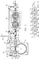
cable 32, coming from thestraightener 30, is to be inserted into theunderground guide tube 18. This is done with the synergetic blowing and pushing action of theinsertion unit 28. Inside the housing 34 (two sections fastened together, seeFIGURE 5 , only the bottom section of this equipment shown) thecable 32 is pushed by means of a mechanically (electric or pneumatic) drivenwheel 36 that has an outer layer of machined hard metal with a groove for engaging the cable. In order to grip the cable a second (not mechanically driven)idler wheel 38 is pushed against thedrive wheel 36. Pushing of thewheel 38, which can pivot onarm 40, is done viaspring 42 by turning around theadjustment wheel 44 to control the pushing force of thedrive wheel 38. - The
cable 32 enters thehousing 34 via a conical feed-through 46 that is cut to fit exactly the cable size. This feed-through is mounted on a splittablecylindrical entrance duct 48 that makes an airtight seal when the housing is closed. Theguidetube 18 is received in a splittable,cylindrical exit duct 49 also making airtight sealing. Theguide tube 18 extends into thehousing 34 until almost touching the wheels, to avoid buckling. Optionally theguide tube 18 can be mounted using a push/pull connector 50. Air is fed using aconnection 52 viavalve 54. The sections of the housing are closed with bolts and nuts through holes 56. For proper alignment, pin-and-holes 58 are used. - Referring again to
FIGURE 1 , sources of compressed air and hydraulic power (or electric power) are connected to thecable feeder 28. Preferably, the compressed air A is provided by acompressor 64 throughdelivery conduit 66 at 5 to 10.6 cubic meters per minute (175 to 375 cubic feet per minute (CFM)) and 6.3 to 12.3 Kg per square centimetre (90 to 175 pounds per square inch (PSI)). For the small size cables, installed in the guide tubes, in principle a capacity of 0.57 to 1.4 cubic meters per minute (20 to 50 cubic feet per minute) is sufficient. - An entrance duct clamp releasably holds the entrance duct for guiding the
cable 32 toward thecable driver 36. Preferably, the entrance duct is a length of polyethylene tubing. - The
air injection block 34 is provided with an entrance seal insert and an exit seal insert adapted to permit passage of thecable 32 while maintaining an airtight seal. Theinjection block 34, entrance seal insert and exit seal insert are each separable into two generally symmetrical halves to permit installation of thecable 32. The seal inserts are removable and replaceable with similar inserts adapted for different cable and conduit diameters. The entrance seal insert provides a passage slightly larger than the cable. A pair of gaskets is provided in the entrance seal insert to seal around the cable. An inlet fitting is provided to permit injection of compressed air into theinjection block 34. - The exit duct clamp is secured to the
air injection block 34 to secure the duct to the injection block. The injection block defines aplenum 68 closed by the entrance seal insert and the exit seal insert. An end portion of theguide duct 18 is releasably held in the exit duct clamp. Preferably, theguide duct 28 is a length of cylindrical polyethylene tubing. A duct seal, such as a pair of gaskets, is provided to seal around the guide duct. The exit duct clamp and duct seal the injection block and guide duct to direct passage of air from the plenum into the guide duct. - Referring to
FIGURE 1 ,FIGURE 2 andFIGURE 9 , prior to installation of the cable into theguide duct 18, a leading end of thecable 32 is sealed with a smooth plug orend cap 33 having a diameter only slightly larger than that of the cable, e.g., made of brass, or other low friction material. Anend cap 33 is attached to the forward end of each cable preferably by a screw-threaded union, and is tapered or torpedo-shaped and rounded on end to avoid sticking of the cable in the guide tube. - To set up the
cable feeder 28, as shown inFIGURE 1 and2 , a length of cable is unrolled from thereel 34 and inserted in theentrance duct 48. The cable is positioned so that it extends from the end of the entrance duct approximately the length of the cable feeder. Acable 32 with the smooth plug end cap is inserted into theguide duct 18. The cable feeder is positioned adjacent the cable. The drive wheels, injection block, clamps and seal inserts are separated to provide a generally horizontal passage into which the cable is transversely inserted. The separated parts are then reassembled, closed, and secured to the entrance duct, cable, and guide duct in the cable feeder. - The compressed air, hydraulic source, and/or electric power are connected and initiated to pressurize the
plenum 68 and to activate the hydraulic system and the control system. Compressed air A flows at high speed along the cable, propelling the cable through the guide duct. The actuator is switched on to provide hydraulic fluid (or compressed air or electric power) to the motors, and the drive wheels rotate, advancing thecable 32 through theconduit 18. - According to the present invention, after the
cable 32 exits thecable launching equipment 28 but prior to entry into theguide tube 18 in the protectiveunderground duct 10, thecable 32 is lubricated by running it through apressurized lubricator unit 100 as shown inFIGURE 1 ,FIGURE 3 andFIGURE 5 . Field-testing has demonstrated that the coefficient of friction of rubbing engagement of the cable against a protective duct (or guide tube) is a major limiting factor in determining how far a cable can be blown-in. Maximum blowing distance can be obtained when the blowing force equals the frictional force resisting movement of the cable. Consequently the maximum blowing distance varies substantially linearly with the coefficient of friction (through straight duct trajectories). It has been demonstrated by field testing that post-launch lubrication of the cable, under pressurized duct conditions, can substantially reduce the coefficient of friction in the duct, yielding a surprising increase in blowing distance by a factor of 10 or more as compared with the non-lubricated case. - Referring again to
FIGURE 1 andFIGURE 2 , a schematic representation is given ofcable blowing equipment 28 in combination with thecable lubricator 100. Thecable straightener 30 may be used in combination with relatively large cables having a large diameter (e.g., 3.9 - 5.0 mm) exceeding a certain minimum size, e.g., in the range of from 1.6 to 2.0 mm and smaller diameters, but is not preferred for use on the smaller cables. - In the preferred embodiment, microcables 32 with diameters ranging from 1.6 to 2.0 mm have been blown into
guide tubes - The
cable 32 is blown into theguide tube 18 using thecable blowing equipment 28. Immediately after the blowing equipment thecable lubricator 100 is placed, coupled to a lead-in section of the guide tube, and this lead-in section is extended, also by couplings, to theguide tube 18 into which the cable has to be installed. - In the exemplary embodiment shown in
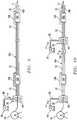
FIGURE 5 andFIGURE 7 thecable lubricator 100 consists of a cylindrical sidewall section orshell 70 of high density polyethylene (HDPE) material with an outer diameter of 40 mm and an internal cylindrical bore 71 forming a lubrication compartment into which compressed foam-plugs FIGURE 6 ) andcylindrical cable guiders housing 70 are closed air-tight (but not sealing the air flow in the longitudinal direction) using threaded duct-couplings tubular connector fittings - In the preferred embodiment, a large fraction A1 of the pressurized airflow A is shunted or bypassed around the lubricator into the duct via T-connectors 98,102,
angled connectors bypass conduit 108. The smaller remainder fraction A2 of the pressurized airflow passes through thelongitudinal airflow passage 71 of the lubricator compartment in contact with the foam-plug applicators - The
cable 32 is pushed through thecable lubricator 100 in wiping contact with the foam plugs during blowing. To eliminate buckling of the cable in the relatively large space (compared to the 4 mm diameter guide tube) of the 40 mmdiameter lubrication compartment 71, the cable is guided at several places within the compartment. The bore size of the 4mm tube connectors coupling apertures - To further eliminate cable buckling,
cylindrical cable guiders guide apertures guiders duct housing 70 is avoided sufficiently to guide the cable without kinking. These lengths may be shorter when the cable guiders are supported and fixed in the lubricator. - The cable-
guiders separate sub-compartments plug 72, in order to be sure that enough lubricant is applied and to provision the reservoir with as much lubricant as possible. Thefirst compartment 110 could also contain lubricant only, without a foam-plug, and thelast compartment 114 would contain a "just wet" foam-plug 76. The foam-plugs 74 in between can vary from "wet" to "dry." - Preferably, each foam plug is a little less "wet" starting from the first "wet"
foam plug 72, thereby forming a lubrication gradient within the pressurized lubrication passage. This arrangement applies a thin film of lubricant rather than a thick viscous layer that would cause the cable to stick to the duct sidewall. Also, this arrangement ensures a transfer of lubricant from the more-wet compartments to the less-wet compartments, thus avoiding premature drying out of the less-wet foam plugs. - Installation of the
cable lubricator 100 is accomplished as follows. The T-connectors 98,102, duct-couplings housing 70, foam-plugs cable guiders cable 32. Then the cable-guiders and the foam-plugs are pressed into the duct-piece (the foam-plugs have to be squeezed and compressed for proper fitting). Next the duct-couplings are screwed to the duct housing. Finally the air-bypass conduit is connected to the T-connectors to complete the cable lubricator. Then thecable 32 can be blown into guide tubes connected to the cable lubricator. - For new installations the
cable 32 is cut in front of thecable lubricator 100 and a new lead-in section of guide tube is connected. When the cable reel is empty a new cable can be mechanically coupled to the old cable and pushed through thecable straightner 30,cable blowing equipment 28 andcable lubricator 100. It is also possible to use a straight rod, which is pushed through an empty cable lubricator without opening it, attach the cable to it, and then pull the cable through the lubricator. - When all lubricant is used or the foam plugs become too dry to be effective, the cable lubricator can be opened and refilled through a sealable access port, for example via a screw cap fitting 116 (
FIGURE 3 and FIGURE 4 ), mounted air-tight and extending through thebypass housing 130. It is also possible to use a lubricating nipple with an internal check valve for refill. The lubricant should be a viscous lubricating material that can flow and be absorbed into a fluid permeable applicator. Various lubricants are available from commercial sources and can be used for cable lubrication. However, a water-based emulsion lubricant sold by American Polywater Corporation of Stillwater, Minnesota under its trademark Polywater® Prelube™2000 is preferred. That lubricating material has the consistency of hand lotion under ambient conditions and is readily absorbed into open cell plastic foam materials, natural sponges, woven fiber wicks and other fluid permeable applicator materials. - Various fluid permeable materials can be used to fabricate the lubricant applicator plugs, including synthetic foams, natural sponges and woven fiber wicks. In the preferred embodiment, the preferred fluid permeable applicator material is a resilient cellular plastic foam, such as open cell polyether or polyester polyurethane foam, rubber latex, and polyethylene or vinyl polymers. When a polyurethane foam is used, the foam has a nominal density in the range of about 9.7 to about 19.4 Kg per cubic meter (about 0.6 to about 1.2 pounds per cubic foot), preferably about 13 to about 16.2 Kg per cubic meter (about 0.8 to about 1.0 pounds per cubic foot), and an indentation force deflection (IFD) in the range of about 1.8 to about 6.8 kg (about 4 to about 15 pounds), preferably about 3.6 to about 5.4 Kg (about 8 to about 12 pounds). (Test Method ASTM D3574)
- The nominal density in pounds per cubic foot (PCF) polyurethane foam applicator material in one embodiment as measured according to ASTM D3574 is 8.1 to 81 Kg per cubic meter (0.5 to 5 PCF), in one embodiment 12.1 to 32.4 Kg per cubic meter (0.75 to 2 PCF), and in one embodiment 20.2 to 21.9 Kg per cubic meter (1.25 to 1.35 PCF). The foam firmness measured in terms of indentation force deflection (IFD) under ASTM D3574, also referred to as initial load deflection (ILD), for the foam plug material in one embodiment is 6.8 to 45.4 Kg (15 to 100 lbs), in one embodiment 20.4 to 25Kg (45 to 55 lbs), and in one embodiment 22.7 to 23.6 Kg (50 to 52 lbs), respectively. Open cell foams, having the foregoing range of densities and ILD values are compressible under mechanical pressure and will return to their original shape when the pressure is removed.
- The
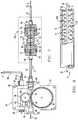
cable lubricator 100 can function well with bypass airflow Al as shown inFIGURE 3 andFIGURE 5 , applying a thin film of lubricant on the cable jacket. In these embodiments bypass airflow is provided by theconduit 108 that is coupled in parallel airflow relation with thelubricator airflow passage 71 for diverting substantially all of the pressurized airflow around the applicator and into the duct for blowing-assisted transport of the cable through the duct trajectory. - Bypass airflow is also provided by the alternative lubricator embodiment shown in
FIGURE 3 and FIGURE 4 . In this arrangement, the airflow bypass means is formed by a largediameter housing shell 130 that completely encloses thelubricator housing 70. The lubricator is radially spaced from the tubular housing and is held in cable-running alignment with the housing shell byradial spacer fins annulus 138 between the housing shell andlubricator housing 70 forms a bypass airflow passage for conveying a large fraction A1 of the pressurized airflow from thelaunch apparatus 28 into theguide tube 18. - In this alternative embodiment the airflow passage of the lubricator is pressurized by a relatively small airflow A2. Only a single foam-plug
absorbent applicator 72 is placed in the lubricant reservoir housing for wiping lubricant onto thecable 32 as it moves through thepressurized airflow passage 71. This arrangement may be used for running relatively stiff cable for which cable-guiders are not needed, e.g., fiber optic cable in which the fibers are enclosed in small diameter steel tubing. - It is also possible to block or eliminate the bypass airflow as shown in
FIGURE 7 , whereby the entire pressurized airflow A is discharged through thelubricator 100. In that case a sufficient amount of pressurized air will still flow through the holes in the duct couplings and cable guiders, and also through the foam plugs, to propel the cable through the guide tube. - With full airflow through the lubricator (
FIGURE 7 ),small lubricant droplets 120 are stripped away from the foam plugs and become entrained in the pressurized airflow as a "shower" of lubricant droplets, thus forming an aerosol mixture that lubricates thebore 19 of theguide tube 18 as the droplets disperse through the guide tube, as shown inFIGURE 8 . The nature of this "shower" depends on the air pressure, length of the guide tube in which the cable is installed and on the lubricant filling of the cable lubricator. Trial and error will determine the parameters for best lubricating effect by this method. - It is also possible, by using a splittable duct access fitting, to place one or more
additional cable lubricators 100 further in the duct trajectory, for example in series withtandem duct sections FIGURE 9 . In this cascade arrangement of lubricators, where the mechanical pushing forces provided by the initialcable launching equipment 28 may be absent or very small, the friction forces of the cable through the cable lubricator will be low enough to allow the viscous forces of the bypass airflow A1 to compensate for the reduced pushing force at the remote locations. - Also additional pushing/
blowing equipment additional lubricator 100 can be placed further in the duct trajectory, blowing and lubricating in tandem (cascade). This can be done at one or more remote operative positions in thetandem duct sections cable launching equipment 28, as shown inFIGURE 10 . There is a vent fitting 140 installed in theduct section 18A just before reaching the second blowing station. Thevent 140 exhausts the pressurized airflow A from the first blower out of theduct section 18A before it reaches thesecond duct section 18B. By this arrangement there is no airflow communication between the duct sections, since there is no practical way to combine the airflow from the first blower into the plenum of the second blower. The airflow and pushing forces from the first blowing station supplies the needed propelling forces for the cable over thefirst duct section 18A. The second launching apparatus will also propel the cable, but the new airflow provided by the second blower is only effective in thesecond duct section 18B, downstream of the second blower. - The following tests were performed with the lubricator embodiment shown in
FIGURE 5 (air bypass open). Blowing was done with 10 bars (10.2 Kg per square centimeter or 145 psi) air-pressure unless otherwise specified. In all experiments the guide tubes were open at 585 meters (1,919 feet) from the point where the cable is launched. - First attempt: Un-lubricated installation. Blowing transport of cable started with a rate of advance of 35 m/min (115 feet/min) but stopped because of frictional resistance after reaching only 50 m (164 feet) in the duct trajectory.
- Second attempt: Lubricating the tube with water-based lubricant and a foam-plug blown through. Blowing transport of cable started with a rate of advance of 35 m/min (115 feet/min) and the speed had dropped to 7 m/min (23 feet/min) after reaching 225 m (738 feet) in the duct trajectory.
- Third attempt: Using the cable lubricator (and another unlubricated tube). Blowing started with 35 m/min (115 feet/min) and the speed had dropped to 8 m/min (26 feet/min) after reaching 500 m (1,640 feet) in the duct trajectory.
- First attempt: Installation with no further lubricating. Blowing started with 35 m/min (115 feet/min) and the speed dropped to 5 m/min (16.4 feet/min) at reaching 235 m (771 feet) in the duct trajectory.
- Second attempt: Using the cable lubricator (and another unlubricated tube). Blowing started with 35 m/min (115 feet/min) and the speed was still the same upon reaching 585 m (1,919 feet) in the duct trajectory while the pressure was only 7.1 Kg per square centimeter (7 bars or 101.5 pounds per square inch).
- The effect of post-launch lubrication with the
pressurized cable lubricator 100 is an improvement by a factor of 10 or more in blowing length with respect to the non-lubricated case. Moreover the blowing results reproduce better when using the cable lubricator. The blowing distance improvement of the cable lubricator is also much more striking than the improvement of lubricating the guide tubes alone (or using pre-lubricated tubes), which was an unexpected and surprising improvement. - For the sake of completeness, it is further noted that the lubrication method of the invention is suitable for installing copper wire signal cables and power cables as well as optical fiber cables.
Claims (30)
- A method of installing a cable (32) in a duct (18) wherein the cable is inserted into the duct by pushing means (36, 38) and by a launching apparatus (28) including a source of pressurized air (64) for propelling the cable at least in part by pressurized air blowing-assisted transport through the duct, wherein the cable is lubricated by a cable lubricator (100) comprising a lubrication compartment (70) comprising the steps:
pushing the cable (32) by means arranged in the launching apparatus (28);
connecting the launching apparatus (28) in airflow communication with the duct (18) through the lubrication compartment of the cable lubricator (100);
running the cable (32) through the lubrication compartment (70) after the cable exits from the launching apparatus (28);
pressurizing the lubrication compartment (70) with pressurized airflow from the launching apparatus (28); and
applying a viscous lubricant to the cable (32) as the cable moves through the pressurized lubrication compartment (70). - A method of installing a cable according to claim 1,characterized by the step of:diverting (98, 102, 104, 106, 108, 130) a substantial fraction of the pressurized airflow around the lubrication compartment (70) into the duct (18) downstream of the cable lubricator (100) for assisting blowing transport of the cable through the duct.
- A method of installing a cable according to claim 1 or 2, wherein the lubricant applying step is performed by running the cable in wiping contact engagement with a fluid permeable material (72, 74, 76) that is wetted by a viscous lubricant contained in the lubrication compartment (70).
- A method of installing a cable according to any of the claims 1-3, including the step of:limiting radial deflection (78, 80, 82, 84) of the cable (18) as it moves through the lubrication compartment (70).
- A method of installing a cable according to claim 4, wherein the limiting step ischaracterized by:constraining movement of the cable through guide apertures (78A-84A) formed in guide blocks (78-84) contained in the lubrication compartment (70).
- A method of installing a cable according to any of the claims 1-5, wherein the lubricant application step ischaracterized by:bringing the cable into surface wiping contact against two or more serially disposed fluid permeable applicators (72, 76) having a viscous lubricant content varying from "very wet" to "just wet," and with one or more intermediate applicators (74) having a viscous lubricant content varying from "wet" to "less wet."
- A method of installing a cable according to claim 1, including the step of:stripping droplets (120) of lubricant from a reservoir of viscous lubricant contained in the lubrication compartment (70) and entraining the droplets of lubricant in the pressurized air moving through the lubrication compartment.
- A method of installing a cable according to claim 1 or 2, including the step of:supplying lubricant from a reservoir of viscous lubricant and wetting the cable with the lubricant as the cable (18) moves through the lubrication compartment (70).
- A method according to any of the claims 1-8, wherein a further duct (18B) is provided and comprising the further steps of:installing a second cable lubricator (100) with a lubrication compartment (70) connecting the duct (18A) in airflow communication with the further duct (18B);running the cable through the lubrication compartment of the second cable lubricator (100) before the cable enters the further duct and applying lubricant on the cable with lubricant in a as it moves through the lubrication compartment of the second lubricator; anddiverting (108) a substantial fraction of the pressurized airflow conveyed through the duct around the second cable lubricator and into the further duct downstream of the second cable lubricator for blowing-assisted transport of the cable through the further duct.
- A method according to any of the claims 1-8, wherein a further duct (18B) is provided and comprising the further steps of:installing a second cable launching apparatus (28) including a second source of pressurized air (64) in an operative position between the duct (18A) and the further duct (18B) for propelling the cable at least in part by pressurized air blowing-assisted transport in the further duct;installing a second cable lubricator (100) with a lubrication compartment (70) connecting the second launching apparatus in airflow communication with the further duct; andrunning the cable through the lubrication compartment of the second cable lubricator before the cable enters the further duct and applying lubricant on the cable as it moves through the pressurized lubrication compartment of the second lubricator.
- Apparatus for installing a cable (32) in a duct (18) according to a method according to any of the preceding claims, comprising:means (36, 38) for pushing the cable into the duct;a launching apparatus (28) including a source of pressurized air (64) for propelling a cable at least in part by pressurized air blowing-assisted transport in the duct; anda cable lubricator (100) including a compartment (70) forming a lubrication passage, and lubrication means (72,74,76) disposed in the compartment for applying a viscous lubricant onto the cable as the cable moves through the lubrication passage,characterized in that the pushing means (36, 38) are arranged in the launching apparatus; that the cable lubricator (100) is connected in an operative position between the launching apparatus (28) and the duct (18), and that the lubrication passage is adapted to convey pressurized air from the launch apparatus into the duct.
- Apparatus for installing a cable according to claim 11, including:apparatus (98, 102, 104, 106, 108, 130) coupled in bypass flow relation with the lubricator (100) for diverting a substantial fraction of the pressurized airflow around the lubrication passage into the duct downstream of the cable lubricator for assisting blowing transport of the cable through the duct.
- Apparatus according to claim 12, wherein the apparatus is adapted to install the cable in a further duct (18B) and comprises
a further cable lubricator (100) connected between the duct (18) and the further duct (18B) at a location downstream relative to the first mentioned cable lubricator (100), the further cable lubricator including a compartment (70) forming a lubrication passage for conveying pressurized airflow from the duct into the further duct, and lubrication means (72-76) disposed in the housing of the further lubricator for applying lubricant onto the cable as the cable and pressurized air move through the lubrication passage of the further lubricator; and
further bypass apparatus (108) coupled in bypass flow relation with the further cable lubricator for diverting a substantial fraction of the pressurized airflow around the lubrication compartment of the further lubricator into the further duct for assisting blowing transport of the cable through the further duct. - Apparatus according to claim 12, wherein the apparatus is adapted to install the cable in a further duct (18B) and comprises
a further launching apparatus (28) disposed in cable running alignment between the duct (18) and the further duct (18B) for receiving the cable at a remote location downstream relative to the first mentioned launching apparatus (28), the further launching apparatus including a further source of pressurized air(64) and further pushing means (36, 38) for propelling the cable at least in part by pressurized air blowing-assisted transport in the further duct;
a further cable lubricator (100) connected in an operative position between the further launch apparatus and the further duct, the further cable lubricator including a compartment (70) forming a lubricator passage for conveying pressurized air provided by the further launching apparatus into the further duct, and lubrication means (72-76) disposed in the lubricator housing for applying lubricant onto the cable as the cable and pressurized air move through the lubricator passage into the further duct; and
further bypass apparatus (108) coupled in bypass flow relation with the further cable lubricator (100) for diverting a substantial fraction of the pressurized airflow around the lubrication compartment of the further lubricator into the further duct for assisting blowing transport of the cable through the further duct. - An apparatus according to any of the claims 11-14,characterized in that the lubricator compartment provides a bypass airflow passage (130) in parallel airflow relation with the lubrication passage, to divert a portion of the pressurized airflow around the lubrication passage for discharge into the duct (18).
- An apparatus according to claim 15, wherein the bypass airflow passage ischaracterized by a tubular conduit (138) having an inlet end portion coupled in airflow communication with the lubrication passage upstream of the lubrication passage and an outlet end portion coupled in airflow communication with the lubrication passage downstream of the lubricator (100).
- An apparatus according to claim 15,characterized in that the bypass airflow passage comprises a tubular housing (130) adapted for connection in an operative position between a source of pressurized air and the duct, and the lubrication reservoir is enclosed within and spaced from the tubular housing in cable-running alignment with the protective duct.
- An apparatus according to any of the claims 11-17,characterized in that the lubrication passage of the cable lubricator is partitioned into two or more longitudinally spaced compartments, and a plug of fluid permeable material is disposed in at least one of the compartments for wiping the cable as it moves through the lubrication passage.
- An apparatus according to any of the claims 11-18,characterized in that the lubrication means of the cable lubricator comprise a compartment (70) for containing a volume of viscous lubricant, and a sealable refill access port (116) is coupled to the lubrication compartment for replenishing lubricant therein.
- An apparatus according to any of the claims 11-14,characterized in that the lubrication passage of the cable lubricator is partitioned by one or more cable guide blocks (78-84) thereby forming a plurality of longitudinally spaced compartments, and a plug of fluid permeable material (72-76) is disposed in at least one of the compartments for wiping the cable as it moves through the lubrication passage.
- An apparatus according to any of the claims 11-14,characterized in that the lubrication passage of the cable lubricator is partitioned by one or more cable guide blocks (78-84), and each guide block includes a body portion intersected by a longitudinal bore (75A-84A) permitting free longitudinal movement of the cable (32) while limiting radial deflection movement of the cable as the cable moves through the lubrication passage.
- An apparatus according to any of the claims 11-14,characterized in that the lubrication passage of the cable lubricator is partitioned into first, last and one or more intermediate compartments that are longitudinally spaced apart, and a plug of fluid permeable material (72, 76) is disposed in the first compartment and in the last compartment, respectively, for sealing the one or more intermediate compartments and wiping the cable as it moves through the lubrication passage.
- An apparatus according to any of the claims 11-17,characterized in that the lubrication passage of the cable lubricator is partitioned into a first compartment, a last compartment and an intermediate compartment that are longitudinally spaced apart, and the intermediate compartment is filled with a viscous lubricant, and a plug of fluid permeable material (72, 76) is disposed in the first compartment and in the last compartment, respectively, for sealing the intermediate compartment and wiping the cable as it moves through the lubrication passage.
- An apparatus according to any of the claims 11-14,characterized in that the lubrication passage of the cable lubricator is partitioned into three or more compartments that are longitudinally spaced apart, and a plug of fluid permeable material (72, 76) is disposed each compartment, respectively, for wiping the cable as it moves through the lubrication passage, and each successive wiping plug contains a respectively lesser amount of lubricant such that a lubrication gradient is established along the lubrication passage varying from very wet in the first wiping plug to just wet in the last wiping plug.
- An apparatus according to any of the claims 11-14,characterized in that the lubrication passage of the cable lubricator is partitioned by one or more cable guide blocks (78-84) thereby forming a plurality of longitudinally spaced compartments, at least one of the compartments comprising a reservoir for containing a volume of viscous lubricant and a plug of fluid permeable material (72, 74, 76) is disposed in at least one of the compartments for wiping the cable as it moves through the airflow passage.
- An apparatus according to any of the claims 11-14,characterized in that a plug of fluid permeable material is disposed in the lubrication passage of the cable lubricator for introducing a shower of lubricant droplets into compressed air discharged into the protective duct.
- An apparatus according to any of the claims 18, 20 or 22-24,characterized in that the fluid permeable plug comprises a resilient, open cell plastic foam material.
- An apparatus according to any of the claims 18, 20 or 22-24,characterized in that the lubricant applicator comprises a fluid permeable wick of woven fibers.
- An apparatus according to any of the claims 18, 20 or 22-24,characterized in that the lubricant applicator comprises a resilient, compressible natural sponge material.
- Apparatus according to claim 14, including a vent fitting (140) installed in the duct (18) for exhausting the pressurized airflow out of the duct at a location near the point of entry of the cable into the further launching apparatus (28).
Applications Claiming Priority (3)
| Application Number | Priority Date | Filing Date | Title |
|---|---|---|---|
| US10/194,034US6848541B2 (en) | 2002-07-11 | 2002-07-11 | Optical cable installation with cable lubricator |
| US194034 | 2002-07-11 | ||
| PCT/IB2003/003488WO2004008599A1 (en) | 2002-07-11 | 2003-06-30 | Optical cable installation with cable lubricator |
Publications (2)
| Publication Number | Publication Date |
|---|---|
| EP1522130A1 EP1522130A1 (en) | 2005-04-13 |
| EP1522130B1true EP1522130B1 (en) | 2017-11-22 |
Family
ID=30114655
Family Applications (1)
| Application Number | Title | Priority Date | Filing Date |
|---|---|---|---|
| EP03764081.0AExpired - LifetimeEP1522130B1 (en) | 2002-07-11 | 2003-06-30 | Optical cable installation with cable lubricator |
Country Status (4)
| Country | Link |
|---|---|
| US (2) | US6848541B2 (en) |
| EP (1) | EP1522130B1 (en) |
| AU (1) | AU2003250457A1 (en) |
| WO (1) | WO2004008599A1 (en) |
Families Citing this family (35)
| Publication number | Priority date | Publication date | Assignee | Title |
|---|---|---|---|---|
| US7143866B2 (en)* | 2000-11-16 | 2006-12-05 | Wld, Llc | Strand lubrication |
| FR2833770A1 (en)* | 2001-12-17 | 2003-06-20 | Novoplastic Sa | Method of installing high tension underground electric cables, uses high pressure water under pressure as a carrier and cooling medium |
| ES2206010B1 (en)* | 2002-01-24 | 2004-12-01 | Melchor Daumal Castellon | DEVICE FOR THE ASSEMBLY OF DIRECT ANTI-PINCHING SYSTEMS. |
| US20040065444A1 (en)* | 2002-07-03 | 2004-04-08 | Smith David R. | Pulsed deployment of a cable through a conduit located in a well |
| US7992685B2 (en)* | 2002-07-11 | 2011-08-09 | Draka Comteq B.V. | Optical cable lubricator with reservoir |
| ES2273286T3 (en)* | 2003-08-13 | 2007-05-01 | John Michael Holtzhausen | DEVICE AND METHOD FOR ROLLING IN A DUCT. |
| GB0326868D0 (en)* | 2003-11-18 | 2003-12-24 | Wood Group Logging Services In | Fiber optic deployment apparatus and method |
| GB0506568D0 (en)* | 2005-03-31 | 2005-05-04 | British Telecomm | Optical fibre air chamber apparatus |
| MX2008015518A (en) | 2006-08-30 | 2008-12-18 | Afl Telecommunications Llc | Downhole cables with both fiber and copper elements. |
| US7845202B2 (en)* | 2006-09-22 | 2010-12-07 | Assa Abloy Ab | Interchangeable electromechanical lock core |
| EP1914577A1 (en)* | 2006-10-17 | 2008-04-23 | British Telecommunications Public Limited Company | Optical fibre installation apparatus |
| US8459611B2 (en)* | 2007-08-30 | 2013-06-11 | Wesco Distribution, Inc. | System for the simultaneous introduction of two items into a conduit |
| US8387954B2 (en)* | 2007-08-30 | 2013-03-05 | Wesco Distribution, Inc. | System for the simultaneous introduction of two items into a conduit |
| US8413964B2 (en)* | 2007-12-28 | 2013-04-09 | Verizon Patent And Licensing Inc. | Fiber drop installation device |
| EP2075606A1 (en)* | 2007-12-28 | 2009-07-01 | British Telecmmunications public limited campany | Cable installation using induction |
| EP2075608A1 (en)* | 2007-12-28 | 2009-07-01 | British Telecmmunications public limited campany | Cable installation using optical detection |
| GB2459963B (en)* | 2008-05-14 | 2012-07-18 | Tracto Technik | Device and method to split pipe near utilities |
| GB0817639D0 (en)* | 2008-09-26 | 2008-11-05 | British Telecomm | Cable installation apparatus |
| EP2230545A1 (en) | 2009-03-19 | 2010-09-22 | BRITISH TELECOMMUNICATIONS public limited company | Passive remote air flow and cable detection |
| GB0905590D0 (en) | 2009-03-31 | 2009-05-13 | British Telecomm | Blown cable apparatus |
| US8167272B2 (en)* | 2009-07-09 | 2012-05-01 | Toyota Motor Engineering & Manufacturing North America, Inc. | Lubricating systems, lubricant atomizing devices and methods of using the same |
| EP2369388A1 (en) | 2010-03-26 | 2011-09-28 | British Telecommunications public limited company | Optical fibre splice tray assembly |
| DK2606543T3 (en)* | 2010-08-20 | 2014-06-23 | Plumettaz Holding S A | Method of laying out a plurality of successive cable parts to produce a large length cable connection |
| US9780540B2 (en) | 2010-11-16 | 2017-10-03 | Plumettaz Holding S.A. | Duct rod system for installing an elongated element in a conduit |
| EP3106734B1 (en) | 2015-06-19 | 2020-06-03 | ULC Robotics, Inc. | Launch system for a pressurized pipeline |
| IT201800009367A1 (en)* | 2018-10-11 | 2020-04-11 | Prysmian Spa | Method and apparatus for the installation of blowing cables |
| KR101998045B1 (en)* | 2019-01-10 | 2019-07-08 | 박정식 | Feeding apparatus for wire follow |
| WO2020150197A1 (en)* | 2019-01-14 | 2020-07-23 | Ideal Industries, Inc. | System for lubricating cables or the like |
| WO2021055839A1 (en) | 2019-09-20 | 2021-03-25 | Condux International, Inc. | Integrated transmission line installation system |
| CN112963715A (en)* | 2021-04-08 | 2021-06-15 | 浙江坤博精工科技股份有限公司 | Strong type oiling of oozing is protected and is pressed from both sides |
| CN113097930B (en)* | 2021-04-08 | 2022-10-04 | 汉维科技发展有限公司 | Cable tube-penetrating auxiliary tool in multifunctional comprehensive wiring system and using method |
| JPWO2022239532A1 (en)* | 2021-05-11 | 2022-11-17 | ||
| US20250110306A1 (en)* | 2023-10-02 | 2025-04-03 | Jameson, Llc | Method and universal apparatus for optical fiber installation |
| WO2025104439A1 (en) | 2023-11-14 | 2025-05-22 | Emtelle Uk Limited | Cable for installation by pushing, cable pushing tool, methods of installing cables by pushing |
| CN118073024B (en)* | 2024-04-19 | 2024-06-25 | 四川金力电缆集团有限公司 | Manufacturing process for flexible flat cable |
Family Cites Families (31)
| Publication number | Priority date | Publication date | Assignee | Title |
|---|---|---|---|---|
| US3916925A (en)* | 1974-02-19 | 1975-11-04 | Phido Wire Services Co Ltd | Cable cleaning units |
| US4185809A (en) | 1978-01-27 | 1980-01-29 | Nelson Jonnes | Method and apparatus for pulling lightweight cable |
| US4331322A (en)* | 1980-02-25 | 1982-05-25 | Woodruff Harold F | Cable laying apparatus |
| FR2501927A1 (en) | 1981-03-10 | 1982-09-17 | Nonclerq Bernard | METHOD FOR DRAWING CABLES IN CONDUITS |
| US5169126C1 (en) | 1982-11-08 | 2001-05-08 | British Telecomm | Method and apparatus for installing transmission lines |
| US5121901A (en) | 1982-11-08 | 1992-06-16 | British Telecommunications Plc | Sheathed optical fibres and method of installing such fibres |
| US4569420A (en)* | 1982-12-13 | 1986-02-11 | Pickett Wiley J | Lubricating method and system for use in cable pulling |
| US4822005A (en) | 1985-10-16 | 1989-04-18 | Fpl Qualtec, Inc. | Cable pulling system and adaptor |
| US4749059A (en)* | 1986-01-17 | 1988-06-07 | American Polywater Corporation | Apparatus and method for lubricating cables |
| NL193126B (en) | 1987-04-28 | 1998-07-01 | Nederland Ptt | Method and device for arranging a cable in a cable guide tube. |
| GB8813068D0 (en)* | 1988-06-02 | 1988-07-06 | British Telecomm | Transmission line installation |
| FR2655783B1 (en) | 1989-12-13 | 1992-09-11 | Pecot Alain | INJECTION GUN, PARTICULARLY FOR PULLING CABLES IN A LONG LENGTH. |
| DE4202147A1 (en) | 1992-01-27 | 1993-07-29 | Lancier Masch Peter | Feeding a cable into a conduit using compressed air - requires cable attached to piston blown down conduit by compressed with air measuring head recording speed and force |
| EP0620627B1 (en) | 1993-04-10 | 1997-07-02 | Sumitomo Electric Industries, Ltd. | Method and apparatus for inserting a communication wire through a pipeline by air flow |
| US5573225A (en) | 1994-05-06 | 1996-11-12 | Dowell, A Division Of Schlumberger Technology Corporation | Means for placing cable within coiled tubing |
| NL1002363C2 (en) | 1995-03-24 | 1996-09-26 | Nederland Ptt | Removing moisture from hollow conductors such as cable ducts. |
| US5897103A (en) | 1995-07-24 | 1999-04-27 | Koninklijke Ptt Nederland N.V. | Method for installing cables |
| NL1001960C2 (en) | 1995-12-21 | 1997-06-24 | Nederland Ptt | Method of installing a tube or bundle of tubes in an existing tubular channel. |
| NL1001961C2 (en) | 1995-12-21 | 1997-06-24 | Nederland Ptt | A method of installing a tubing with taps for telecommunication cables, as well as a tapping element for use in that method. |
| NL1003130C2 (en) | 1996-05-15 | 1997-11-18 | Nederland Ptt | Puller for installing a cable in a tube as well as a piping provided with such a puller. |
| NL1003249C2 (en) | 1996-05-31 | 1997-12-03 | Nederland Ptt | Tube connector for connecting tubes intended for installing cables therein. |
| NL1003681C2 (en) | 1996-07-25 | 1998-01-28 | Nederland Ptt | Apparatus and method for removing cables from pipes. |
| AU719820B2 (en) | 1996-09-19 | 2000-05-18 | British Telecommunications Public Limited Company | Blowing head |
| NL1004747C2 (en) | 1996-12-11 | 1998-06-15 | Nederland Ptt | Method and device for inserting a cable-like element into an elongated tubular casing wound on or in a container. |
| ATE206824T1 (en) | 1996-12-11 | 2001-10-15 | Koninkl Kpn Nv | METHOD FOR INSERTING A CABLE-LIKE ELEMENT INTO A ROLLED TUBE ON A HOLDER |
| US6116578A (en) | 1997-10-01 | 2000-09-12 | Pruett; Phillip E. | Method for inserting a cable in a duct |
| NL1007210C2 (en) | 1997-10-06 | 1999-04-08 | Koninkl Kpn Nv | Method for installing cables in pipes and device for applying this method. |
| GB9909912D0 (en) | 1999-04-29 | 1999-06-30 | Pirelli General Plc | Method of blowing cable into a duct |
| NL1013901C2 (en) | 1999-12-21 | 2001-06-25 | Koninkl Kpn Nv | Method for installing optical fibers or cables in a tube using a fluid under pressure. |
| FR2807226B1 (en) | 2000-03-31 | 2002-08-09 | Marais Sa | METHOD AND DEVICE FOR PROPELLING A CABLE OR THE LIKE INSIDE A SHEATH |
| JP2001309519A (en) | 2000-04-25 | 2001-11-02 | Furukawa Electric Co Ltd:The | Cable feeding device in pipeline |
- 2002
- 2002-07-11USUS10/194,034patent/US6848541B2/ennot_activeExpired - Lifetime
- 2003
- 2003-06-30AUAU2003250457Apatent/AU2003250457A1/ennot_activeAbandoned
- 2003-06-30EPEP03764081.0Apatent/EP1522130B1/ennot_activeExpired - Lifetime
- 2003-06-30WOPCT/IB2003/003488patent/WO2004008599A1/ennot_activeApplication Discontinuation
- 2004
- 2004-11-17USUS10/990,704patent/US7021426B2/ennot_activeExpired - Lifetime
Also Published As
| Publication number | Publication date |
|---|---|
| WO2004008599A1 (en) | 2004-01-22 |
| US20050067608A1 (en) | 2005-03-31 |
| US20040007699A1 (en) | 2004-01-15 |
| US6848541B2 (en) | 2005-02-01 |
| US7021426B2 (en) | 2006-04-04 |
| AU2003250457A1 (en) | 2004-02-02 |
| EP1522130A1 (en) | 2005-04-13 |
Similar Documents
| Publication | Publication Date | Title |
|---|---|---|
| EP1522130B1 (en) | Optical cable installation with cable lubricator | |
| EP0287225B1 (en) | Optical fibre installation | |
| JP2552589B2 (en) | Power cable and optical fiber insertion method | |
| US6572081B2 (en) | Installation of guide tubes in a protective duct | |
| US5897103A (en) | Method for installing cables | |
| US5467968A (en) | Transmission line installation | |
| US5922995A (en) | Partitioning device for a tubular conduit and method of installation thereof | |
| FI87121C (en) | Method and system for inserting a cable into a cable tube | |
| US4275096A (en) | Method and apparatus for dispensing fluid in a conduit | |
| US7992685B2 (en) | Optical cable lubricator with reservoir | |
| PL213483B1 (en) | Method for removing a cable core from a cable sheath | |
| JPS59104607A (en) | Method and apparatus for installing optical fiber cable | |
| US6711328B2 (en) | Installation bundle with spacer | |
| EP1042696B1 (en) | Method of inserting a light transmitting member into a tube | |
| US5205542A (en) | Optical fibre installation | |
| CZ289441B6 (en) | Method for installing cables and apparatus for making the same | |
| CN108139016B (en) | Method and system for manufacturing pre-insulated piping and pre-insulated piping | |
| CZ351598A3 (en) | A method and apparatus for cleaning and / or inserting a stretching wire into an installation pipe | |
| US20250246885A1 (en) | Device for laying a cable into a duct with a lubricating capacity | |
| Griffioen | Cable in Duct Installation: Lubrication Makes the Difference | |
| JP2001286024A (en) | Lubricant application equipment in cable laying method | |
| JPH03145604A (en) | Cable laying and recovery method | |
| JPH01255413A (en) | Repair work for underground conduit line |
Legal Events
| Date | Code | Title | Description |
|---|---|---|---|
| PUAI | Public reference made under article 153(3) epc to a published international application that has entered the european phase | Free format text:ORIGINAL CODE: 0009012 | |
| 17P | Request for examination filed | Effective date:20041224 | |
| AK | Designated contracting states | Kind code of ref document:A1 Designated state(s):AT BE BG CH CY CZ DE DK EE ES FI FR GB GR HU IE IT LI LU MC NL PT RO SE SI SK TR | |
| AX | Request for extension of the european patent | Extension state:AL LT LV MK | |
| DAX | Request for extension of the european patent (deleted) | ||
| GRAP | Despatch of communication of intention to grant a patent | Free format text:ORIGINAL CODE: EPIDOSNIGR1 | |
| INTG | Intention to grant announced | Effective date:20170207 | |
| GRAS | Grant fee paid | Free format text:ORIGINAL CODE: EPIDOSNIGR3 | |
| GRAJ | Information related to disapproval of communication of intention to grant by the applicant or resumption of examination proceedings by the epo deleted | Free format text:ORIGINAL CODE: EPIDOSDIGR1 | |
| GRAL | Information related to payment of fee for publishing/printing deleted | Free format text:ORIGINAL CODE: EPIDOSDIGR3 | |
| INTC | Intention to grant announced (deleted) | ||
| RAP1 | Party data changed (applicant data changed or rights of an application transferred) | Owner name:PRYSMIAN NETHERLANDS B.V. | |
| GRAR | Information related to intention to grant a patent recorded | Free format text:ORIGINAL CODE: EPIDOSNIGR71 | |
| GRAA | (expected) grant | Free format text:ORIGINAL CODE: 0009210 | |
| INTG | Intention to grant announced | Effective date:20171012 | |
| AK | Designated contracting states | Kind code of ref document:B1 Designated state(s):AT BE BG CH CY CZ DE DK EE ES FI FR GB GR HU IE IT LI LU MC NL PT RO SE SI SK TR | |
| REG | Reference to a national code | Ref country code:GB Ref legal event code:FG4D | |
| REG | Reference to a national code | Ref country code:CH Ref legal event code:EP | |
| REG | Reference to a national code | Ref country code:IE Ref legal event code:FG4D | |
| REG | Reference to a national code | Ref country code:AT Ref legal event code:REF Ref document number:949232 Country of ref document:AT Kind code of ref document:T Effective date:20171215 | |
| REG | Reference to a national code | Ref country code:DE Ref legal event code:R096 Ref document number:60350787 Country of ref document:DE | |
| REG | Reference to a national code | Ref country code:NL Ref legal event code:FP | |
| REG | Reference to a national code | Ref country code:AT Ref legal event code:MK05 Ref document number:949232 Country of ref document:AT Kind code of ref document:T Effective date:20171122 | |
| PG25 | Lapsed in a contracting state [announced via postgrant information from national office to epo] | Ref country code:ES Free format text:LAPSE BECAUSE OF FAILURE TO SUBMIT A TRANSLATION OF THE DESCRIPTION OR TO PAY THE FEE WITHIN THE PRESCRIBED TIME-LIMIT Effective date:20171122 Ref country code:SE Free format text:LAPSE BECAUSE OF FAILURE TO SUBMIT A TRANSLATION OF THE DESCRIPTION OR TO PAY THE FEE WITHIN THE PRESCRIBED TIME-LIMIT Effective date:20171122 Ref country code:FI Free format text:LAPSE BECAUSE OF FAILURE TO SUBMIT A TRANSLATION OF THE DESCRIPTION OR TO PAY THE FEE WITHIN THE PRESCRIBED TIME-LIMIT Effective date:20171122 | |
| PG25 | Lapsed in a contracting state [announced via postgrant information from national office to epo] | Ref country code:BG Free format text:LAPSE BECAUSE OF FAILURE TO SUBMIT A TRANSLATION OF THE DESCRIPTION OR TO PAY THE FEE WITHIN THE PRESCRIBED TIME-LIMIT Effective date:20180222 Ref country code:GR Free format text:LAPSE BECAUSE OF FAILURE TO SUBMIT A TRANSLATION OF THE DESCRIPTION OR TO PAY THE FEE WITHIN THE PRESCRIBED TIME-LIMIT Effective date:20180223 Ref country code:AT Free format text:LAPSE BECAUSE OF FAILURE TO SUBMIT A TRANSLATION OF THE DESCRIPTION OR TO PAY THE FEE WITHIN THE PRESCRIBED TIME-LIMIT Effective date:20171122 | |
| PG25 | Lapsed in a contracting state [announced via postgrant information from national office to epo] | Ref country code:SK Free format text:LAPSE BECAUSE OF FAILURE TO SUBMIT A TRANSLATION OF THE DESCRIPTION OR TO PAY THE FEE WITHIN THE PRESCRIBED TIME-LIMIT Effective date:20171122 Ref country code:DK Free format text:LAPSE BECAUSE OF FAILURE TO SUBMIT A TRANSLATION OF THE DESCRIPTION OR TO PAY THE FEE WITHIN THE PRESCRIBED TIME-LIMIT Effective date:20171122 Ref country code:EE Free format text:LAPSE BECAUSE OF FAILURE TO SUBMIT A TRANSLATION OF THE DESCRIPTION OR TO PAY THE FEE WITHIN THE PRESCRIBED TIME-LIMIT Effective date:20171122 Ref country code:CY Free format text:LAPSE BECAUSE OF FAILURE TO SUBMIT A TRANSLATION OF THE DESCRIPTION OR TO PAY THE FEE WITHIN THE PRESCRIBED TIME-LIMIT Effective date:20171122 Ref country code:CZ Free format text:LAPSE BECAUSE OF FAILURE TO SUBMIT A TRANSLATION OF THE DESCRIPTION OR TO PAY THE FEE WITHIN THE PRESCRIBED TIME-LIMIT Effective date:20171122 | |
| REG | Reference to a national code | Ref country code:DE Ref legal event code:R097 Ref document number:60350787 Country of ref document:DE | |
| PG25 | Lapsed in a contracting state [announced via postgrant information from national office to epo] | Ref country code:IT Free format text:LAPSE BECAUSE OF FAILURE TO SUBMIT A TRANSLATION OF THE DESCRIPTION OR TO PAY THE FEE WITHIN THE PRESCRIBED TIME-LIMIT Effective date:20171122 Ref country code:RO Free format text:LAPSE BECAUSE OF FAILURE TO SUBMIT A TRANSLATION OF THE DESCRIPTION OR TO PAY THE FEE WITHIN THE PRESCRIBED TIME-LIMIT Effective date:20171122 | |
| PLBE | No opposition filed within time limit | Free format text:ORIGINAL CODE: 0009261 | |
| STAA | Information on the status of an ep patent application or granted ep patent | Free format text:STATUS: NO OPPOSITION FILED WITHIN TIME LIMIT | |
| 26N | No opposition filed | Effective date:20180823 | |
| PG25 | Lapsed in a contracting state [announced via postgrant information from national office to epo] | Ref country code:SI Free format text:LAPSE BECAUSE OF FAILURE TO SUBMIT A TRANSLATION OF THE DESCRIPTION OR TO PAY THE FEE WITHIN THE PRESCRIBED TIME-LIMIT Effective date:20171122 | |
| GBPC | Gb: european patent ceased through non-payment of renewal fee | Effective date:20180630 | |
| REG | Reference to a national code | Ref country code:BE Ref legal event code:MM Effective date:20180630 | |
| PG25 | Lapsed in a contracting state [announced via postgrant information from national office to epo] | Ref country code:MC Free format text:LAPSE BECAUSE OF FAILURE TO SUBMIT A TRANSLATION OF THE DESCRIPTION OR TO PAY THE FEE WITHIN THE PRESCRIBED TIME-LIMIT Effective date:20171122 Ref country code:LU Free format text:LAPSE BECAUSE OF NON-PAYMENT OF DUE FEES Effective date:20180630 | |
| REG | Reference to a national code | Ref country code:IE Ref legal event code:MM4A | |
| PG25 | Lapsed in a contracting state [announced via postgrant information from national office to epo] | Ref country code:IE Free format text:LAPSE BECAUSE OF NON-PAYMENT OF DUE FEES Effective date:20180630 Ref country code:GB Free format text:LAPSE BECAUSE OF NON-PAYMENT OF DUE FEES Effective date:20180630 Ref country code:FR Free format text:LAPSE BECAUSE OF NON-PAYMENT OF DUE FEES Effective date:20180630 | |
| PG25 | Lapsed in a contracting state [announced via postgrant information from national office to epo] | Ref country code:BE Free format text:LAPSE BECAUSE OF NON-PAYMENT OF DUE FEES Effective date:20180630 | |
| PG25 | Lapsed in a contracting state [announced via postgrant information from national office to epo] | Ref country code:TR Free format text:LAPSE BECAUSE OF FAILURE TO SUBMIT A TRANSLATION OF THE DESCRIPTION OR TO PAY THE FEE WITHIN THE PRESCRIBED TIME-LIMIT Effective date:20171122 | |
| PG25 | Lapsed in a contracting state [announced via postgrant information from national office to epo] | Ref country code:PT Free format text:LAPSE BECAUSE OF FAILURE TO SUBMIT A TRANSLATION OF THE DESCRIPTION OR TO PAY THE FEE WITHIN THE PRESCRIBED TIME-LIMIT Effective date:20171122 Ref country code:HU Free format text:LAPSE BECAUSE OF FAILURE TO SUBMIT A TRANSLATION OF THE DESCRIPTION OR TO PAY THE FEE WITHIN THE PRESCRIBED TIME-LIMIT; INVALID AB INITIO Effective date:20030630 | |
| PGFP | Annual fee paid to national office [announced via postgrant information from national office to epo] | Ref country code:NL Payment date:20220626 Year of fee payment:20 | |
| PGFP | Annual fee paid to national office [announced via postgrant information from national office to epo] | Ref country code:DE Payment date:20220629 Year of fee payment:20 | |
| PGFP | Annual fee paid to national office [announced via postgrant information from national office to epo] | Ref country code:CH Payment date:20220706 Year of fee payment:20 | |
| REG | Reference to a national code | Ref country code:DE Ref legal event code:R071 Ref document number:60350787 Country of ref document:DE Ref country code:CH Ref legal event code:PL | |
| REG | Reference to a national code | Ref country code:NL Ref legal event code:MK Effective date:20230629 |