EP1518582B1 - Rapid-exchange balloon catheter with hypotube shaft - Google Patents
Rapid-exchange balloon catheter with hypotube shaftDownload PDFInfo
- Publication number
- EP1518582B1 EP1518582B1EP04255818AEP04255818AEP1518582B1EP 1518582 B1EP1518582 B1EP 1518582B1EP 04255818 AEP04255818 AEP 04255818AEP 04255818 AEP04255818 AEP 04255818AEP 1518582 B1EP1518582 B1EP 1518582B1
- Authority
- EP
- European Patent Office
- Prior art keywords
- hypotube
- proximal
- distal
- balloon
- balloon catheter
- Prior art date
- Legal status (The legal status is an assumption and is not a legal conclusion. Google has not performed a legal analysis and makes no representation as to the accuracy of the status listed.)
- Expired - Lifetime
Links
- 230000007704transitionEffects0.000claimsabstractdescription16
- 238000007373indentationMethods0.000claimsabstractdescription12
- 239000010935stainless steelSubstances0.000claimsdescription2
- 229910001220stainless steelInorganic materials0.000claimsdescription2
- 238000004519manufacturing processMethods0.000description6
- 238000000034methodMethods0.000description6
- 238000002399angioplastyMethods0.000description5
- 230000008901benefitEffects0.000description4
- 229910052751metalInorganic materials0.000description4
- 239000002184metalSubstances0.000description4
- 229920000642polymerPolymers0.000description4
- 238000007789sealingMethods0.000description4
- 238000011282treatmentMethods0.000description3
- 208000031481Pathologic ConstrictionDiseases0.000description2
- 239000000853adhesiveSubstances0.000description2
- 230000001070adhesive effectEffects0.000description2
- 230000017531blood circulationEffects0.000description2
- 230000008878couplingEffects0.000description2
- 238000010168coupling processMethods0.000description2
- 238000005859coupling reactionMethods0.000description2
- 239000012530fluidSubstances0.000description2
- 230000003902lesionEffects0.000description2
- 239000000463materialSubstances0.000description2
- 229910001000nickel titaniumInorganic materials0.000description2
- 208000037804stenosisDiseases0.000description2
- 230000036262stenosisEffects0.000description2
- 208000012287ProlapseDiseases0.000description1
- 208000007536ThrombosisDiseases0.000description1
- RTAQQCXQSZGOHL-UHFFFAOYSA-NTitaniumChemical compound[Ti]RTAQQCXQSZGOHL-UHFFFAOYSA-N0.000description1
- HZEWFHLRYVTOIW-UHFFFAOYSA-N[Ti].[Ni]Chemical compound[Ti].[Ni]HZEWFHLRYVTOIW-UHFFFAOYSA-N0.000description1
- 230000002411adverseEffects0.000description1
- 238000005452bendingMethods0.000description1
- 230000005540biological transmissionEffects0.000description1
- 210000004204blood vesselAnatomy0.000description1
- 238000007664blowingMethods0.000description1
- 238000000576coating methodMethods0.000description1
- 238000004891communicationMethods0.000description1
- 150000001875compoundsChemical class0.000description1
- 238000007887coronary angioplastyMethods0.000description1
- 239000002783friction materialSubstances0.000description1
- 238000001746injection mouldingMethods0.000description1
- 230000010354integrationEffects0.000description1
- 150000002739metalsChemical class0.000description1
- 230000000926neurological effectEffects0.000description1
- HLXZNVUGXRDIFK-UHFFFAOYSA-Nnickel titaniumChemical compound[Ti].[Ti].[Ti].[Ti].[Ti].[Ti].[Ti].[Ti].[Ti].[Ti].[Ti].[Ni].[Ni].[Ni].[Ni].[Ni].[Ni].[Ni].[Ni].[Ni].[Ni].[Ni].[Ni].[Ni].[Ni]HLXZNVUGXRDIFK-UHFFFAOYSA-N0.000description1
- 238000007888peripheral angioplastyMethods0.000description1
- 210000005259peripheral bloodAnatomy0.000description1
- 239000011886peripheral bloodSubstances0.000description1
- 238000003825pressingMethods0.000description1
- 229910001285shape-memory alloyInorganic materials0.000description1
- 230000001225therapeutic effectEffects0.000description1
- 239000010936titaniumSubstances0.000description1
- 229910052719titaniumInorganic materials0.000description1
- 208000019553vascular diseaseDiseases0.000description1
Images


Classifications
- A—HUMAN NECESSITIES
- A61—MEDICAL OR VETERINARY SCIENCE; HYGIENE
- A61M—DEVICES FOR INTRODUCING MEDIA INTO, OR ONTO, THE BODY; DEVICES FOR TRANSDUCING BODY MEDIA OR FOR TAKING MEDIA FROM THE BODY; DEVICES FOR PRODUCING OR ENDING SLEEP OR STUPOR
- A61M25/00—Catheters; Hollow probes
- A61M25/0021—Catheters; Hollow probes characterised by the form of the tubing
- A61M25/0023—Catheters; Hollow probes characterised by the form of the tubing by the form of the lumen, e.g. cross-section, variable diameter
- A61M25/0026—Multi-lumen catheters with stationary elements
- A61M25/0029—Multi-lumen catheters with stationary elements characterized by features relating to least one lumen located at the middle part of the catheter, e.g. slots, flaps, valves, cuffs, apertures, notches, grooves or rapid exchange ports
- A—HUMAN NECESSITIES
- A61—MEDICAL OR VETERINARY SCIENCE; HYGIENE
- A61M—DEVICES FOR INTRODUCING MEDIA INTO, OR ONTO, THE BODY; DEVICES FOR TRANSDUCING BODY MEDIA OR FOR TAKING MEDIA FROM THE BODY; DEVICES FOR PRODUCING OR ENDING SLEEP OR STUPOR
- A61M25/00—Catheters; Hollow probes
- A61M25/0043—Catheters; Hollow probes characterised by structural features
- A61M25/0054—Catheters; Hollow probes characterised by structural features with regions for increasing flexibility
- A—HUMAN NECESSITIES
- A61—MEDICAL OR VETERINARY SCIENCE; HYGIENE
- A61M—DEVICES FOR INTRODUCING MEDIA INTO, OR ONTO, THE BODY; DEVICES FOR TRANSDUCING BODY MEDIA OR FOR TAKING MEDIA FROM THE BODY; DEVICES FOR PRODUCING OR ENDING SLEEP OR STUPOR
- A61M25/00—Catheters; Hollow probes
- A61M25/10—Balloon catheters
- A61M25/104—Balloon catheters used for angioplasty
- A—HUMAN NECESSITIES
- A61—MEDICAL OR VETERINARY SCIENCE; HYGIENE
- A61M—DEVICES FOR INTRODUCING MEDIA INTO, OR ONTO, THE BODY; DEVICES FOR TRANSDUCING BODY MEDIA OR FOR TAKING MEDIA FROM THE BODY; DEVICES FOR PRODUCING OR ENDING SLEEP OR STUPOR
- A61M25/00—Catheters; Hollow probes
- A61M25/01—Introducing, guiding, advancing, emplacing or holding catheters
- A61M2025/0183—Rapid exchange or monorail catheters
- A—HUMAN NECESSITIES
- A61—MEDICAL OR VETERINARY SCIENCE; HYGIENE
- A61M—DEVICES FOR INTRODUCING MEDIA INTO, OR ONTO, THE BODY; DEVICES FOR TRANSDUCING BODY MEDIA OR FOR TAKING MEDIA FROM THE BODY; DEVICES FOR PRODUCING OR ENDING SLEEP OR STUPOR
- A61M25/00—Catheters; Hollow probes
- A61M25/0021—Catheters; Hollow probes characterised by the form of the tubing
- A61M25/0023—Catheters; Hollow probes characterised by the form of the tubing by the form of the lumen, e.g. cross-section, variable diameter
- A61M25/0026—Multi-lumen catheters with stationary elements
- A61M25/0032—Multi-lumen catheters with stationary elements characterized by at least one unconventionally shaped lumen, e.g. polygons, ellipsoids, wedges or shapes comprising concave and convex parts
Definitions
- the present inventionrelates generally to medical devices, and more particularly to a balloon catheter with a hypotube shaft.
- Balloon cathetersare used in a variety of therapeutic applications, including intravascular catheters for procedures such as angioplasty. Approximately one million angioplasties are performed worldwide each year to treat vascular disease, including coronary, neurological and peripheral blood vessels partially or totally blocked or narrowed by a lesion or stenosis. By way of example, the present invention will be described in relation to coronary and peripheral angioplasty treatments. However, it should be understood that the present invention relates to any balloon catheter having a hypotube shaft according to the present invention as recited in the following claims, and is not limited to angioplasty. Most balloon catheters have a relatively long and flexible tubular shaft defining one or more passages or lumens, and have an inflatable balloon attached near one end of the shaft.
- distal endThis end of the catheter where the balloon is located is customarily referred to as the "distal” end, while the other end is called the “proximal” end.
- proximal end of the shaftgenerally leads to a hub coupling at the proximal end for connecting the lumen(s) to various equipment.
- the interior of the balloonis connected to one of the lumen(s) extending through the shaft for the purpose of selectively inflating and deflating the balloon.
- This lumenis of course referred to as the inflation lumen.
- the catheter shaftalso may define a second passage for slidingly receiving a guidewire, referred to as a guidewire lumen.
- the guidewire lumenextends between a distal guidewire port at the catheter distal end, and a proximal guidewire port.
- the catheter of the present inventionhas a "rapid exchange" configuration in which the proximal guidewire port is located somewhere between the balloon and the proximal hub.
- the balloonmay define an inflatable central portion defining an inflated size, flanked by a pair of proximal and distal conical portions, flanked by a pair of proximal and distal legs or collars. The proximal and distal collars may be affixed to the shaft.
- Common treatment methods for using such a balloon catheterinclude advancing a guidewire into the body of a patient, by directing the guidewire distal end percutaneously through an incision and along a body passage until it is located within or beyond the desired site.
- the term "desired site"refers to the location in the patient's body currently selected for treatment by a health care professional.
- the guidewiremay be advanced before, or simultaneously with, a balloon catheter.
- the balloon cathetermay be advanced or withdrawn along a path defined by the guidewire. After the balloon is disposed within the desired site, it can be selectively inflated to press outward on the body passage at relatively high pressure to a relatively constant diameter, in the case of an inelastic or non-compliant balloon material.
- This outward pressing of a constriction or narrowing at the desired site in a body passageis intended to partially or completely re-open or dilate that body passageway or lumen, increasing its inner diameter or cross-sectional area.
- this procedureis referred to as angioplasty.
- the objective of this procedureis to increase the inner diameter or cross-sectional area of the vessel passage or lumen through which blood flows, to encourage greater blood flow through the newly expanded vessel.
- the narrowing of the body passageway lumenis called a lesion or stenosis, and may be formed of hard plaque or viscous thrombus.
- Stentsare generally tubular scaffolds for holding a vessel or body passage open.
- a balloon catheterhaving an optimum combination of various performance characteristics, which may be selected among: flexibility, lubricity, pushability, trackability, crossability, low profile and others.
- Flexibilitymay relate to bending stiffness of a medical device (balloon catheter and/or stent, for example) in a particular region or over its entire length, or may relate to the material hardness of the components.
- Lubricitymay refer to reducing friction by using low-friction materials or coatings.
- Pushabilitymay relate to the column strength of a device or system along a selected path.
- Trackabilitymay refer to a capability of a device to successfully follow a desired path, for example without prolapse.
- Crossabilitymay be clarified by understanding that physicians prefer to reach the desired site with the balloon catheter while encountering little or no friction or resistance.
- Profilemay refer to a maximum lateral dimension of the balloon catheter, at any point along its length.
- hypotube shaft of the present inventionprovides various advantages, which may include: pushability, torsional strength, low profile, etc. Some embodiments of the present invention may also provide additional benefits, including lower cost and ease of manufacture, a relatively few number of component parts, etc.
- the balloon catheterhas a shaft extending from a proximal end of the catheter to a distal end.
- the shafthas a proximal section and a distal polymer section.
- the proximal sectionincludes a metal hypotube, which has a proximal cylindrical tubular portion, an intermediate tubular portion with a longitudinal indentation, and a distal portion.
- the longitudinal indentationmay be shallower in a proximal direction, and deeper in the distal direction.
- the distal portion of the hypotubemay have an arcuate cross-section or a wirelike shape, etc.
- a proximal hubmay be provided at the proximal end, affixed to the proximal hypotube.
- the hubhas a locking fitting for connecting the inflation lumen to a device for inflation and deflation.
- the distal section of the shaftincludes an inner and outer tube extending generally between the hypotube and the balloon.
- the inner and outer tubesare affixed near their proximal ends a point on the hypotube; and they are affixed near their distal ends to the balloon.
- the inner tubedefines a guidewire lumen extending from a distal guidewire port which is at or near the catheter distal end, to a proximal guidewire port which is at or near the proximal end of the inner tube.
- An inflation lumenis defined by the shaft, extending from a proximal inflation port defined by the proximal hub, through the hypotube and then through an annular space defined between the inner and outer tubes, into the balloon.
- the hypotubedefines a transition point at a distal end of the indented tubing portion, and at a proximal end of the distal portion. At or near this transition, the proximal ends of the inner and outer tubular bodies are sealed to the hypotube. At this transition seal, the proximal end of the inner tubular body may be partially received within a distal portion of the longitudinal indentation of the hypotube, and the outer tubular body proximal end surrounds and is sealed to both the inner body and the hypotube. A smooth flexibility transition is thus provided between the tubular portions of the hypotube and the more flexible distal shaft section.
- the proximal hypotube portion of the shaftmay have much greater column strength, which will tend to enhance the pushability of the balloon catheter, yet without adversely affecting flexibility in the distal portion of the shaft where flexibility is relatively more important.
- a balloon catheter systemis depicted, with one of the preferred embodiments of the present invention being shown generally at 10.
- the balloon catheter of Figure 1has an inflatable balloon 12, a relatively long and flexible tubular shaft 14, and a hub 16.
- the balloon 12is affixed to the shaft 14 near a distal end of the shaft 14, and the hub 16 is affixed to the proximal end of the shaft 14.
- the shaftdefines at least two passages or lumens, one ofwhich is an inflation lumen 18 connected to the balloon 12 for the purpose of selectively inflating and deflating the balloon 12.
- the inflation lumen 18thus provides fluid communication between the interior of the balloon 12 at the distal end of the inflation lumen, and a hub inflation port 20 having a coupling or luer-lock fitting at the proximal end for connecting the inflation lumen to a source of pressurized inflation fluid (not shown) in the conventional manner.
- a second lumen defined by the catheter 10is a guidewire lumen 26 is adapted to receive an elongated flexible guidewire 28 in a sliding fashion. The guidewire 28 and catheter 10 may thus be advanced or withdrawn independently, or the catheter 10 may be guided along a path selected with the guidewire 28.
- a distal portion of the shaft 14is constructed of an inner and outer tubular body 22 and 24.
- the inner body 22defines the guidewire lumen 26, while a distal portion of the inflation lumen 18 is defined by an annular space between the inner and outer tubular bodies 22 and 24.
- the guidewire lumen 26extends through the inner tubular body 22 from a distal guidewire port 30 near the catheter distal end to a proximal guidewire port 32 near a proximal end of the inner body 22.
- a proximal portion of the shaft 14is constructed of a hypotube 34 component.
- the hypotube 34is affixed to the hub 16, and has a proximal cylindrical tubular portion 36, an intermediate tubular portion 38 with a longitudinal indentation 40, and a distal portion 42 with an arcuate cross-section.
- the proximal cylindrical tubular portion 36may of course have a taper, as indicated in Figure 4 with outer dimensions A and B, in which dimension A may be larger than dimension B for example. This taper is also indicated in Figure 8a with angle D.
- the longitudinal indentation 40is shallower in the proximal direction, and deeper in the distal direction.
- a transition pointis 44 defined on the hypotube 34 at a distal end of the longitudinally indented intermediate tubular portion 38, and at a proximal end of the distal portion 42 of the hypotube.
- the longitudinal position of this transitionis indicated in Figure 4 as location C.
- the proximal ends of the inner and outer tubular bodies 22 and 24are sealed to the hypotube 34.
- the proximal end of the inner tubular body 22is partially received within a distal portion of the longitudinal indentation 40 of the hypotube 34.
- the hypotubeis preferably made of metal which is selected to be biocompatible, such as for example stainless steel.
- Other acceptable metalsmay include titanium, a nickel titanium based shape memory alloy such as nitinol, etc.
- the hypotube shaft design of the present inventionprovides various advantages which will become apparent to those skilled in the art, including: a proximal shaft portion that was high column strength and high torque transmission, low profile, an integral and smooth flexibility transition near the proximal guidewire port, as well as more efficient and cost-efficient manufacturing due to relatively few component parts.
- the inflation lumen 18extends from the inflation port 20, through a proximal portion of the inflation lumen 18 defined by the hypotube, through a distal portion of the inflation lumen 18 defined by the annular space between the inner and outer bodies 22 and 24, and into the balloon.
- the various portions of the hypotube componentare preferably integral and unitary, and may be made with any of numerous manufacturing techniques. For example, a single piece of tubing may be ground down to form the distal extension, and then the intermediate portion may be compressed to form the indentation.
- the longitudinal indentationalso tends to make the hypotube intermediate portion more flexible than the hypotube proximal portion, which is preferably cylindrical. Again, a relatively smooth transition in flexibility at various points along the length of the catheter is preferable.
- hypotube and distal portionrather than a separate hypotube and stiffening wire which are affixed together, is also preferable.
- Another reason the present invention improves cost-effectiveness of manufacturingis that only one intermediate shaft seal is needed, rather than a separate seal of hypotube to polymer tube and a seal at the proximal guidewire port.
- Hypotube 50has a proximal tubular portion 52, an intermediate tubular portion 54 with a longitudinal indentation 60 that has a compound shape with a steeper proximal indent, and a distal portion 56 with an arcuate cross-section.
- the balloon catheter and stent delivery system of the present inventionmay be made using various methods, many of which are known in the art, including extruding polymer tubes, injection-molding the proximal hub, and extruding a balloon parison and then blowing the parison into a balloon having the desired properties. It is also known to affix polymer components to each other by heat-sealing, or by using an adhesive such as a UV-cured adhesive.
- another advantage of the present inventionis that the crescent-shaped tubular portion of the hypotube at the transition will tend to hold itself open during sealing of the inner and outer bodies to the hypotube. Accordingly, a conventional removable sealing mandrel to keep the inflation lumen open during sealing is unnecessary.
- a stent of any suitable type or configurationmay be provided with the catheter of the present invention, such as the well-known Palmaz-Schatz balloon expandable stent and the successful BX Velocity stent.
- Various kinds and types of stentsare available in the market, and many different currently available stents are acceptable for use in the present invention, as well as new stents which may be developed in the future.
- the stentmay be a cylindrical metal mesh stent having an initial crimped outer diameter, which may be forcibly expanded by the balloon to a deployed diameter. When deployed in a body passageway of a patient, the stent may be designed to preferably press radially outward to hold the passageway open.
- Figure 22shows a cross-section view of a balloon catheter with a stent 46.
Landscapes
- Health & Medical Sciences (AREA)
- Life Sciences & Earth Sciences (AREA)
- Heart & Thoracic Surgery (AREA)
- Hematology (AREA)
- Engineering & Computer Science (AREA)
- Anesthesiology (AREA)
- Biomedical Technology (AREA)
- Pulmonology (AREA)
- Biophysics (AREA)
- Animal Behavior & Ethology (AREA)
- General Health & Medical Sciences (AREA)
- Public Health (AREA)
- Veterinary Medicine (AREA)
- Vascular Medicine (AREA)
- Child & Adolescent Psychology (AREA)
- Media Introduction/Drainage Providing Device (AREA)
Abstract
Description
- The present invention relates generally to medical devices, and more particularly to a balloon catheter with a hypotube shaft.
- Balloon catheters are used in a variety of therapeutic applications, including intravascular catheters for procedures such as angioplasty. Approximately one million angioplasties are performed worldwide each year to treat vascular disease, including coronary, neurological and peripheral blood vessels partially or totally blocked or narrowed by a lesion or stenosis. By way of example, the present invention will be described in relation to coronary and peripheral angioplasty treatments. However, it should be understood that the present invention relates to any balloon catheter having a hypotube shaft according to the present invention as recited in the following claims, and is not limited to angioplasty.
Most balloon catheters have a relatively long and flexible tubular shaft defining one or more passages or lumens, and have an inflatable balloon attached near one end of the shaft. This end of the catheter where the balloon is located is customarily referred to as the "distal" end, while the other end is called the "proximal" end. The proximal end of the shaft generally leads to a hub coupling at the proximal end for connecting the lumen(s) to various equipment. - The interior of the balloon is connected to one of the lumen(s) extending through the shaft for the purpose of selectively inflating and deflating the balloon. This lumen is of course referred to as the inflation lumen.
- The catheter shaft also may define a second passage for slidingly receiving a guidewire, referred to as a guidewire lumen. The guidewire lumen extends between a distal guidewire port at the catheter distal end, and a proximal guidewire port. The catheter of the present invention has a "rapid exchange" configuration in which the proximal guidewire port is located somewhere between the balloon and the proximal hub. Structurally, the balloon may define an inflatable central portion defining an inflated size, flanked by a pair of proximal and distal conical portions, flanked by a pair of proximal and distal legs or collars. The proximal and distal collars may be affixed to the shaft.
- Examples of this type of balloon catheter are shown in the following patents, which are co-owned with the present invention:
United States Patent number 5,304,197 , entitled "Balloons For Medical Devices And Fabrication Thereof," issued to Pinchuk et al. on April 19, 1994, and also inUnited States Patent number 5,370,615 (closest prior art), entitled "Balloon Catheter For Angioplasty," issued to Johnson on December 6,1994. - Common treatment methods for using such a balloon catheter include advancing a guidewire into the body of a patient, by directing the guidewire distal end percutaneously through an incision and along a body passage until it is located within or beyond the desired site. The term "desired site" refers to the location in the patient's body currently selected for treatment by a health care professional. The guidewire may be advanced before, or simultaneously with, a balloon catheter. When the guidewire is within the balloon catheter guidewire lumen, the balloon catheter may be advanced or withdrawn along a path defined by the guidewire. After the balloon is disposed within the desired site, it can be selectively inflated to press outward on the body passage at relatively high pressure to a relatively constant diameter, in the case of an inelastic or non-compliant balloon material.
- This outward pressing of a constriction or narrowing at the desired site in a body passage is intended to partially or completely re-open or dilate that body passageway or lumen, increasing its inner diameter or cross-sectional area. In the case of a blood vessel, this procedure is referred to as angioplasty. The objective of this procedure is to increase the inner diameter or cross-sectional area of the vessel passage or lumen through which blood flows, to encourage greater blood flow through the newly expanded vessel. The narrowing of the body passageway lumen is called a lesion or stenosis, and may be formed of hard plaque or viscous thrombus.
- Some balloon catheters are used to deliver and deploy stents or other medical devices, in a manner generally known in the art. Stents, for example, are generally tubular scaffolds for holding a vessel or body passage open.
- It is desirable to provide a balloon catheter having an optimum combination of various performance characteristics, which may be selected among: flexibility, lubricity, pushability, trackability, crossability, low profile and others. Flexibility may relate to bending stiffness of a medical device (balloon catheter and/or stent, for example) in a particular region or over its entire length, or may relate to the material hardness of the components. Lubricity may refer to reducing friction by using low-friction materials or coatings. Pushability may relate to the column strength of a device or system along a selected path. Trackability may refer to a capability of a device to successfully follow a desired path, for example without prolapse. Crossability may be clarified by understanding that physicians prefer to reach the desired site with the balloon catheter while encountering little or no friction or resistance. Profile may refer to a maximum lateral dimension of the balloon catheter, at any point along its length.
- The hypotube shaft of the present invention provides various advantages, which may include: pushability, torsional strength, low profile, etc. Some embodiments of the present invention may also provide additional benefits, including lower cost and ease of manufacture, a relatively few number of component parts, etc.
- The balloon catheter has a shaft extending from a proximal end of the catheter to a distal end. The shaft has a proximal section and a distal polymer section. The proximal section includes a metal hypotube, which has a proximal cylindrical tubular portion, an intermediate tubular portion with a longitudinal indentation, and a distal portion. The longitudinal indentation may be shallower in a proximal direction, and deeper in the distal direction. The distal portion of the hypotube may have an arcuate cross-section or a wirelike shape, etc.
- A proximal hub may be provided at the proximal end, affixed to the proximal hypotube. The hub has a locking fitting for connecting the inflation lumen to a device for inflation and deflation.
- The distal section of the shaft includes an inner and outer tube extending generally between the hypotube and the balloon. The inner and outer tubes are affixed near their proximal ends a point on the hypotube; and they are affixed near their distal ends to the balloon. The inner tube defines a guidewire lumen extending from a distal guidewire port which is at or near the catheter distal end, to a proximal guidewire port which is at or near the proximal end of the inner tube. An inflation lumen is defined by the shaft, extending from a proximal inflation port defined by the proximal hub, through the hypotube and then through an annular space defined between the inner and outer tubes, into the balloon.
- The hypotube defines a transition point at a distal end of the indented tubing portion, and at a proximal end of the distal portion. At or near this transition, the proximal ends of the inner and outer tubular bodies are sealed to the hypotube. At this transition seal, the proximal end of the inner tubular body may be partially received within a distal portion of the longitudinal indentation of the hypotube, and the outer tubular body proximal end surrounds and is sealed to both the inner body and the hypotube. A smooth flexibility transition is thus provided between the tubular portions of the hypotube and the more flexible distal shaft section.
- In contrast to the distal shaft portion, the proximal hypotube portion of the shaft may have much greater column strength, which will tend to enhance the pushability of the balloon catheter, yet without adversely affecting flexibility in the distal portion of the shaft where flexibility is relatively more important.
- Embodiments of the invention will now be described by way of example with reference to the accompanying drawings, in which:
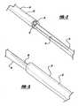
Figure 1 is an external perspective view of a rapid-exchange balloon catheter;Figure 2 is a partial perspective view of an intermediate portion of a balloon catheter;Figure 3 is a partial external perspective view of the intermediate portion ofFigure 2 ;Figure 4 is a partial external perspective view of a hypotube component;Figure 5 is a cross-section view of an intermediate portion of a balloon catheter;Figure 6 is a partial external perspective view of a proximal hub, strain relief, and hypotube;Figure 7 is a side view of a hypotube;Figure 8 is a top view of the hypotube ofFigure 7 ;Figure 9-14 are cross-section views of the hypotube ofFigures 7 and 8 , along the lines 9-9 through 14-14, respectively;Figure 15 is a side view of another hypotube;Figures 16-20 are cross-section views of the hypotube ofFigure 15 , along the lines 16-16 through 20-20, respectively;Figure 21 is a partial longitudinal cross-section view of a hypotube;Figure 22 is a partial longitudinal cross-section view of a balloon catheter and stent; andFigures 8a and 15a are partial expanded views of portions of hypotubes.- The following description of the preferred embodiments of the present invention is merely illustrative in nature, and as such it does not limit in any way the present invention, its application, or uses.
- Referring to the drawings, a balloon catheter system is depicted, with one of the preferred embodiments of the present invention being shown generally at 10. The balloon catheter of
Figure 1 has aninflatable balloon 12, a relatively long and flexibletubular shaft 14, and ahub 16. Theballoon 12 is affixed to theshaft 14 near a distal end of theshaft 14, and thehub 16 is affixed to the proximal end of theshaft 14. - The shaft defines at least two passages or lumens, one ofwhich is an
inflation lumen 18 connected to theballoon 12 for the purpose of selectively inflating and deflating theballoon 12. Theinflation lumen 18 thus provides fluid communication between the interior of theballoon 12 at the distal end of the inflation lumen, and ahub inflation port 20 having a coupling or luer-lock fitting at the proximal end for connecting the inflation lumen to a source of pressurized inflation fluid (not shown) in the conventional manner.
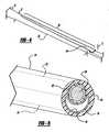
A second lumen defined by thecatheter 10 is aguidewire lumen 26 is adapted to receive an elongatedflexible guidewire 28 in a sliding fashion. Theguidewire 28 andcatheter 10 may thus be advanced or withdrawn independently, or thecatheter 10 may be guided along a path selected with theguidewire 28. - In the illustrated embodiment, a distal portion of the
shaft 14 is constructed of an inner and outertubular body inner body 22 defines theguidewire lumen 26, while a distal portion of theinflation lumen 18 is defined by an annular space between the inner and outertubular bodies guidewire lumen 26 extends through the innertubular body 22 from adistal guidewire port 30 near the catheter distal end to aproximal guidewire port 32 near a proximal end of theinner body 22. - A proximal portion of the
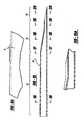
shaft 14 is constructed of ahypotube 34 component. Thehypotube 34 is affixed to thehub 16, and has a proximal cylindricaltubular portion 36, an intermediatetubular portion 38 with alongitudinal indentation 40, and adistal portion 42 with an arcuate cross-section. The proximal cylindricaltubular portion 36 may of course have a taper, as indicated inFigure 4 with outer dimensions A and B, in which dimension A may be larger than dimension B for example. This taper is also indicated inFigure 8a with angle D. - The
longitudinal indentation 40 is shallower in the proximal direction, and deeper in the distal direction. A transition point is 44 defined on thehypotube 34 at a distal end of the longitudinally indented intermediatetubular portion 38, and at a proximal end of thedistal portion 42 of the hypotube. The longitudinal position of this transition is indicated inFigure 4 as location C. At or near thistransition 44, the proximal ends of the inner and outertubular bodies hypotube 34. At this transition seal, the proximal end of the innertubular body 22 is partially received within a distal portion of thelongitudinal indentation 40 of thehypotube 34. - The hypotube is preferably made of metal which is selected to be biocompatible, such as for example stainless steel. Other acceptable metals may include titanium, a nickel titanium based shape memory alloy such as nitinol, etc. The hypotube shaft design of the present invention provides various advantages which will become apparent to those skilled in the art, including: a proximal shaft portion that was high column strength and high torque transmission, low profile, an integral and smooth flexibility transition near the proximal guidewire port, as well as more efficient and cost-efficient manufacturing due to relatively few component parts.
- The
inflation lumen 18 extends from theinflation port 20, through a proximal portion of theinflation lumen 18 defined by the hypotube, through a distal portion of theinflation lumen 18 defined by the annular space between the inner andouter bodies - The various portions of the hypotube component are preferably integral and unitary, and may be made with any of numerous manufacturing techniques. For example, a single piece of tubing may be ground down to form the distal extension, and then the intermediate portion may be compressed to form the indentation.
- The longitudinal indentation also tends to make the hypotube intermediate portion more flexible than the hypotube proximal portion, which is preferably cylindrical. Again, a relatively smooth transition in flexibility at various points along the length of the catheter is preferable.
- The integration of the hypotube and distal portion, rather than a separate hypotube and stiffening wire which are affixed together, is also preferable.
- Another reason the present invention improves cost-effectiveness of manufacturing is that only one intermediate shaft seal is needed, rather than a separate seal of hypotube to polymer tube and a seal at the proximal guidewire port.
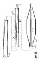
- An additional arrangement of the hypotube of the present invention is shown in
Figures 15-20 .Hypotube 50 has a proximaltubular portion 52, an intermediatetubular portion 54 with alongitudinal indentation 60 that has a compound shape with a steeper proximal indent, and adistal portion 56 with an arcuate cross-section. - The balloon catheter and stent delivery system of the present invention may be made using various methods, many of which are known in the art, including extruding polymer tubes, injection-molding the proximal hub, and extruding a balloon parison and then blowing the parison into a balloon having the desired properties. It is also known to affix polymer components to each other by heat-sealing, or by using an adhesive such as a UV-cured adhesive.
- During manufacture of the transition seal, another advantage of the present invention is that the crescent-shaped tubular portion of the hypotube at the transition will tend to hold itself open during sealing of the inner and outer bodies to the hypotube. Accordingly, a conventional removable sealing mandrel to keep the inflation lumen open during sealing is unnecessary.
- A stent of any suitable type or configuration may be provided with the catheter of the present invention, such as the well-known Palmaz-Schatz balloon expandable stent and the successful BX Velocity stent. Various kinds and types of stents are available in the market, and many different currently available stents are acceptable for use in the present invention, as well as new stents which may be developed in the future. The stent may be a cylindrical metal mesh stent having an initial crimped outer diameter, which may be forcibly expanded by the balloon to a deployed diameter. When deployed in a body passageway of a patient, the stent may be designed to preferably press radially outward to hold the passageway open.
Figure 22 shows a cross-section view of a balloon catheter with a stent 46.
Claims (10)
- A balloon catheter having a proximal end and a distal end for medically treating a patient, comprising:a hypotube (34; 50) having a proximal tubular portion (36; 52), an intermediate tubular portion (38; 54) having a longitudinal indentation (40; 60), and a distal portion (42; 56);an inner tubular body (22) having a proximal and distal end, and defining a proximal and distal guidewire port at each end respectively, and a guidewire lumen (26) extending between the guidewire ports;an outer tubular body (24) surrounding at least a portion of the inner tubular body (22); the proximal ends of the inner and outer tubular bodies being affixed together and sealed to the hypotube (34; 50) at a point defined at or near a transition between the intermediate and distal portions of the hypotube (34; 50);a balloon (12) affixed to the inner and outer tubular bodies at or near their distal ends;an inflation lumen (18) extending from the hypotube proximal end, through the hypotube (34; 50) proximal and intermediate tubular portions, and through an annular space between the outer and inner tubular bodies, into an interior of the balloon;the distal portion (42; 56) of the hypotube (34;50) extending a distance into the outer tubular body (24); providing a transition in flexibility between the tubular portions of the hypotube to the inner and outer bodies;the balloon catheter thus having a rapid-exchange configuration.
- The balloon catheter of Claim 1, wherein the balloon (12) has a central inflatable portion between a proximal collar and a distal collar each affixed to the catheter shaft; the balloon (12) in an initial configuration being deflated, pleated and wrapped around the catheter shaft.
- The balloon catheter of Claim 1, wherein the hypotube (34; 50) is integral and unitary.
- The balloon catheter of Claim 1, wherein the distal portion (42; 56) of the hypotube has an arcuate cross-section.
- The balloon catheter of Claim 1, wherein the longitudinal indentation (40; 60) is shallower in a proximal direction, and deeper in a distal direction.
- The balloon catheter of Claim 1, wherein the proximal portion (36; 52) of the hypotube is cylindrical.
- The balloon catheter of Claim 6, further comprising a tapering portion between the proximal cylindrical portion (36; 52) and the indented intermediate portion (38; 54).
- The balloon catheter of Claim 1 further comprising a stent crimped around the balloon (12).
- The balloon catheter of Claim 1, wherein the proximal ends of the inner and outer tubular bodies are sealed to the hypotube (34; 50) with a single seal.
- The balloon catheter of Claim 1, wherein the hypotube (34; 50) is made of stainless steel.
Applications Claiming Priority (2)
| Application Number | Priority Date | Filing Date | Title |
|---|---|---|---|
| US673650 | 2003-09-29 | ||
| US10/673,650US20050070847A1 (en) | 2003-09-29 | 2003-09-29 | Rapid-exchange balloon catheter with hypotube shaft |
Publications (2)
| Publication Number | Publication Date |
|---|---|
| EP1518582A1 EP1518582A1 (en) | 2005-03-30 |
| EP1518582B1true EP1518582B1 (en) | 2008-06-11 |
Family
ID=34194887
Family Applications (1)
| Application Number | Title | Priority Date | Filing Date |
|---|---|---|---|
| EP04255818AExpired - LifetimeEP1518582B1 (en) | 2003-09-29 | 2004-09-24 | Rapid-exchange balloon catheter with hypotube shaft |
Country Status (4)
| Country | Link |
|---|---|
| US (1) | US20050070847A1 (en) |
| EP (1) | EP1518582B1 (en) |
| AT (1) | ATE397951T1 (en) |
| DE (1) | DE602004014324D1 (en) |
Cited By (1)
| Publication number | Priority date | Publication date | Assignee | Title |
|---|---|---|---|---|
| US8252014B2 (en) | 2004-03-03 | 2012-08-28 | Innovational Holdings Llc. | Rapid exchange balloon catheter with braided shaft |
Families Citing this family (16)
| Publication number | Priority date | Publication date | Assignee | Title |
|---|---|---|---|---|
| WO2008088766A1 (en)* | 2002-03-22 | 2008-07-24 | Cordis Corporation | Rapid-exchange balloon catheter shaft and method |
| US20050070879A1 (en)* | 2003-09-26 | 2005-03-31 | Medtronic Vascular, Inc | Transition section for a catheter |
| US20050070881A1 (en)* | 2003-09-26 | 2005-03-31 | Richard Gribbons | Transition section for a catheter |
| US8057430B2 (en)* | 2009-02-20 | 2011-11-15 | Boston Scientific Scimed, Inc. | Catheter with skived tubular member |
| US9233234B2 (en) | 2010-04-15 | 2016-01-12 | TriReme Medical, LLC | Balloon catheter with improved column strength and torque transmission |
| JP5777936B2 (en)* | 2010-07-16 | 2015-09-09 | テルモ株式会社 | Suction catheter |
| CN107096111A (en) | 2011-05-26 | 2017-08-29 | 雅培心血管系统有限公司 | The conduit of thin hypotube is cut with stairstepping |
| CN205287203U (en) | 2014-09-04 | 2016-06-08 | 雅培心血管系统有限公司 | balloon catheter |
| CN206355424U (en) | 2014-09-04 | 2017-07-28 | 雅培心血管系统有限公司 | Balloon catheter |
| CN106166323A (en) | 2015-05-19 | 2016-11-30 | 雅培心血管系统有限公司 | Balloon catheter |
| EP3095480B1 (en) | 2015-05-19 | 2021-01-13 | Abbott Cardiovascular Systems, Inc. | Catheter having monolithic multilayer distal outer member |
| US10576242B2 (en) | 2015-05-29 | 2020-03-03 | Biosensors International Group, Ltd. | Bi-lumenal tube catheter support system |
| JP5976973B1 (en)* | 2016-03-28 | 2016-08-24 | インター・ノバ株式会社 | Peripheral blood vessel guide catheter with multipolar electrodes |
| CN112402773A (en)* | 2018-07-30 | 2021-02-26 | 郑州大学第一附属医院 | Conical expansion saccule for cardiovascular interventional operation |
| US11612720B2 (en)* | 2019-09-13 | 2023-03-28 | Creganna Unlimited Company | Exit path connector for catheter assembly |
| WO2022115445A1 (en)* | 2020-11-25 | 2022-06-02 | Jihad Ali Mustapha | Peripheral artery balloonn, a hypo-tube for preparing a peripheral artery balloon and methods of use thereof |
Family Cites Families (102)
| Publication number | Priority date | Publication date | Assignee | Title |
|---|---|---|---|---|
| US405524A (en)* | 1889-06-18 | Whip-socket | ||
| US311735A (en)* | 1885-02-03 | Printing-press | ||
| US303013A (en)* | 1884-08-05 | Pen-holder | ||
| US536342A (en)* | 1895-03-26 | George w | ||
| US315727A (en)* | 1885-04-14 | Odometer for vehicles | ||
| US5338157B1 (en)* | 1992-09-09 | 1999-11-02 | Sims Deltec Inc | Systems and methods for communicating with ambulat |
| US3631847A (en)* | 1966-03-04 | 1972-01-04 | James C Hobbs | Method and apparatus for injecting fluid into the vascular system |
| US3812843A (en)* | 1973-03-12 | 1974-05-28 | Lear Siegler Inc | Method and apparatus for injecting contrast media into the vascular system |
| US3885662A (en)* | 1973-12-26 | 1975-05-27 | Ibm | Steerable follower selection mechanism |
| FR2348709A1 (en)* | 1976-04-23 | 1977-11-18 | Pistor Michel | MESOTHERAPIC TREATMENT PROCESS AND INJECTION DEVICE, FORMING AUTOMATIC MICRO-INJECTOR, INCLUDING APPLICATION |
| US4067000A (en)* | 1976-05-28 | 1978-01-03 | Rca Corporation | Remote control transmitter with an audible battery life indicator |
| DE2738406A1 (en)* | 1977-08-25 | 1979-03-08 | Stierlen Maquet Ag | PROCEDURE AND REMOTE CONTROL ARRANGEMENT FOR REMOTE CONTROL OF A MEDICAL DEVICE |
| US4151845A (en)* | 1977-11-25 | 1979-05-01 | Miles Laboratories, Inc. | Blood glucose control apparatus |
| US4193397A (en)* | 1977-12-01 | 1980-03-18 | Metal Bellows Corporation | Infusion apparatus and method |
| US4373527B1 (en)* | 1979-04-27 | 1995-06-27 | Univ Johns Hopkins | Implantable programmable medication infusion system |
| US4268150A (en)* | 1980-01-28 | 1981-05-19 | Laurence Chen | Disposable camera with simplified film advance and indicator |
| CA1169323A (en)* | 1980-06-03 | 1984-06-19 | Anthony M. Albisser | Insulin infusion device |
| US4424720A (en)* | 1980-12-15 | 1984-01-10 | Ivac Corporation | Mechanism for screw drive and syringe plunger engagement/disengagement |
| JPS57163309A (en)* | 1981-04-01 | 1982-10-07 | Olympus Optical Co Ltd | Capsule apparatus for medical use |
| US4529401A (en)* | 1982-01-11 | 1985-07-16 | Cardiac Pacemakers, Inc. | Ambulatory infusion pump having programmable parameters |
| US4435173A (en)* | 1982-03-05 | 1984-03-06 | Delta Medical Industries | Variable rate syringe pump for insulin delivery |
| US4498843A (en)* | 1982-08-02 | 1985-02-12 | Schneider Philip H | Insulin infusion pump |
| US4514732A (en)* | 1982-08-23 | 1985-04-30 | General Electric Company | Technique for increasing battery life in remote control transmitters |
| DE3468173D1 (en)* | 1983-09-07 | 1988-02-04 | Disetronic Ag | Portable infusion apparatus |
| US4562751A (en)* | 1984-01-06 | 1986-01-07 | Nason Clyde K | Solenoid drive apparatus for an external infusion pump |
| US4678408A (en)* | 1984-01-06 | 1987-07-07 | Pacesetter Infusion, Ltd. | Solenoid drive apparatus for an external infusion pump |
| US4684368A (en)* | 1984-06-01 | 1987-08-04 | Parker Hannifin Corporation | Inverted pump |
| US4855746A (en)* | 1984-07-30 | 1989-08-08 | Zenith Electronics Corporation | Multiple device remote control transmitter |
| US4634427A (en)* | 1984-09-04 | 1987-01-06 | American Hospital Supply Company | Implantable demand medication delivery assembly |
| US4755173A (en)* | 1986-02-25 | 1988-07-05 | Pacesetter Infusion, Ltd. | Soft cannula subcutaneous injection set |
| US5349852A (en)* | 1986-03-04 | 1994-09-27 | Deka Products Limited Partnership | Pump controller using acoustic spectral analysis |
| US4778451A (en)* | 1986-03-04 | 1988-10-18 | Kamen Dean L | Flow control system using boyle's law |
| US4685906A (en)* | 1986-03-31 | 1987-08-11 | Murphy William F | Eye-drops application device |
| US5350395A (en)* | 1986-04-15 | 1994-09-27 | Yock Paul G | Angioplasty apparatus facilitating rapid exchanges |
| GB8701731D0 (en)* | 1987-01-27 | 1987-03-04 | Patcentre Benelux Nv Sa | Pumps |
| US4734092A (en)* | 1987-02-18 | 1988-03-29 | Ivac Corporation | Ambulatory drug delivery device |
| US4898579A (en)* | 1987-06-26 | 1990-02-06 | Pump Controller Corporation | Infusion pump |
| US4836752A (en)* | 1987-11-02 | 1989-06-06 | Fisher Scientific Company | Partial restriction detector |
| US4801957A (en)* | 1988-02-18 | 1989-01-31 | Eastman Kodak Company | Disposable single-use camera and accessory re-usable electronic flash unit |
| US4943278A (en)* | 1988-02-29 | 1990-07-24 | Scimed Life Systems, Inc. | Dilatation balloon catheter |
| US5425711A (en)* | 1988-02-29 | 1995-06-20 | Scimed Life Systems, Inc. | Intravascular catheter with distal guide wire lumen and transition member |
| US5304197A (en)* | 1988-10-04 | 1994-04-19 | Cordis Corporation | Balloons for medical devices and fabrication thereof |
| US5205819A (en)* | 1989-05-11 | 1993-04-27 | Bespak Plc | Pump apparatus for biomedical use |
| US5129891A (en)* | 1989-05-19 | 1992-07-14 | Strato Medical Corporation | Catheter attachment device |
| US5411480A (en)* | 1989-06-16 | 1995-05-02 | Science Incorporated | Fluid delivery apparatus |
| US5109850A (en)* | 1990-02-09 | 1992-05-05 | Massachusetts Institute Of Technology | Automatic blood monitoring for medication delivery method and apparatus |
| US5318540A (en)* | 1990-04-02 | 1994-06-07 | Pharmetrix Corporation | Controlled release infusion device |
| US5492534A (en)* | 1990-04-02 | 1996-02-20 | Pharmetrix Corporation | Controlled release portable pump |
| US5007458A (en)* | 1990-04-23 | 1991-04-16 | Parker Hannifin Corporation | Poppet diaphragm valve |
| JPH0451966A (en)* | 1990-06-19 | 1992-02-20 | Toichi Ishikawa | Medical fluid continuous injector |
| US5176662A (en)* | 1990-08-23 | 1993-01-05 | Minimed Technologies, Ltd. | Subcutaneous injection set with improved cannula mounting arrangement |
| US5217482A (en)* | 1990-08-28 | 1993-06-08 | Scimed Life Systems, Inc. | Balloon catheter with distal guide wire lumen |
| EP0498213B1 (en)* | 1991-02-07 | 1997-08-13 | Kabushiki Kaisha Toshiba | X-ray computerized tomographic image data acquisition circuitry capable of performing high speed data acquisition |
| US7074231B2 (en)* | 1991-06-13 | 2006-07-11 | Advanced Cardiovascular Systems, Inc. | Convertible mode vascular catheter system |
| US5213483A (en)* | 1991-06-19 | 1993-05-25 | Strato Medical Corporation | Peristaltic infusion pump with removable cassette and mechanically keyed tube set |
| US5207645A (en)* | 1991-06-25 | 1993-05-04 | Medication Delivery Devices | Infusion pump, treatment fluid bag therefor, and method for the use thereof |
| US5490837A (en)* | 1991-07-05 | 1996-02-13 | Scimed Life Systems, Inc. | Single operator exchange catheter having a distal catheter shaft section |
| US5239326A (en)* | 1991-08-07 | 1993-08-24 | Kabushiki Kaisha Senshukai | Film-loaded disposable camera |
| DE4129271C1 (en)* | 1991-09-03 | 1992-09-17 | Fresenius Ag, 6380 Bad Homburg, De | |
| DE4200030C2 (en)* | 1992-01-02 | 1996-09-12 | Eckhard Prof Dr Alt | catheter |
| US5911716A (en)* | 1992-01-24 | 1999-06-15 | I-Flow Corporation | Platen pump |
| IE930532A1 (en)* | 1993-07-19 | 1995-01-25 | Elan Med Tech | Liquid material dispenser and valve |
| US5370615A (en)* | 1992-12-28 | 1994-12-06 | Cordis Corporation | Balloon catheter for angioplasty |
| US5433710A (en)* | 1993-03-16 | 1995-07-18 | Minimed, Inc. | Medication infusion pump with fluoropolymer valve seat |
| DE4310808C2 (en)* | 1993-04-02 | 1995-06-22 | Boehringer Mannheim Gmbh | Liquid dosing system |
| JP3259267B2 (en)* | 1993-12-28 | 2002-02-25 | ニプロ株式会社 | Chemical injection device |
| US5630710A (en)* | 1994-03-09 | 1997-05-20 | Baxter International Inc. | Ambulatory infusion pump |
| US5643213A (en)* | 1994-03-09 | 1997-07-01 | I-Flow Corporation | Elastomeric syringe actuation device |
| DE4415896A1 (en)* | 1994-05-05 | 1995-11-09 | Boehringer Mannheim Gmbh | Analysis system for monitoring the concentration of an analyte in the blood of a patient |
| US5480383A (en)* | 1994-05-27 | 1996-01-02 | Advanced Cardiovascular Systems, Inc. | Dilation catheter with a smooth transition between a stiff proximal portion and a flexible distal portion |
| JPH0858897A (en)* | 1994-08-12 | 1996-03-05 | Japan Storage Battery Co Ltd | Fluid supply device |
| US5505709A (en)* | 1994-09-15 | 1996-04-09 | Minimed, Inc., A Delaware Corporation | Mated infusion pump and syringe |
| US5637095A (en)* | 1995-01-13 | 1997-06-10 | Minimed Inc. | Medication infusion pump with flexible drive plunger |
| US5741228A (en)* | 1995-02-17 | 1998-04-21 | Strato/Infusaid | Implantable access device |
| US5647853A (en)* | 1995-03-03 | 1997-07-15 | Minimed Inc. | Rapid response occlusion detector for a medication infusion pump |
| US5779676A (en)* | 1995-10-11 | 1998-07-14 | Science Incorporated | Fluid delivery device with bolus injection site |
| US5776103A (en)* | 1995-10-11 | 1998-07-07 | Science Incorporated | Fluid delivery device with bolus injection site |
| WO1997033637A1 (en)* | 1996-03-14 | 1997-09-18 | O'neil, Christine | Patient controllable drug delivery system flow regulating means |
| US5976109A (en)* | 1996-04-30 | 1999-11-02 | Medtronic, Inc. | Apparatus for drug infusion implanted within a living body |
| US5785688A (en)* | 1996-05-07 | 1998-07-28 | Ceramatec, Inc. | Fluid delivery apparatus and method |
| US5726404A (en)* | 1996-05-31 | 1998-03-10 | University Of Washington | Valveless liquid microswitch |
| US5755682A (en)* | 1996-08-13 | 1998-05-26 | Heartstent Corporation | Method and apparatus for performing coronary artery bypass surgery |
| US5748827A (en)* | 1996-10-23 | 1998-05-05 | University Of Washington | Two-stage kinematic mount |
| US5886647A (en)* | 1996-12-20 | 1999-03-23 | Badger; Berkley C. | Apparatus and method for wireless, remote control of multiple devices |
| US5785681A (en)* | 1997-02-25 | 1998-07-28 | Minimed Inc. | Flow rate controller for a medication infusion pump |
| US6061580A (en)* | 1997-02-28 | 2000-05-09 | Randice-Lisa Altschul | Disposable wireless telephone and method for call-out only |
| US5875393A (en)* | 1997-02-28 | 1999-02-23 | Randice-Lisa Altschul | Disposable wireless telephone and method |
| US6071292A (en)* | 1997-06-28 | 2000-06-06 | Transvascular, Inc. | Transluminal methods and devices for closing, forming attachments to, and/or forming anastomotic junctions in, luminal anatomical structures |
| US5961492A (en)* | 1997-08-27 | 1999-10-05 | Science Incorporated | Fluid delivery device with temperature controlled energy source |
| US5858005A (en)* | 1997-08-27 | 1999-01-12 | Science Incorporated | Subcutaneous infusion set with dynamic needle |
| US6527744B1 (en)* | 1997-08-27 | 2003-03-04 | Science Incorporated | Fluid delivery device with light activated energy source |
| US6019747A (en)* | 1997-10-21 | 2000-02-01 | I-Flow Corporation | Spring-actuated infusion syringe |
| US6036670A (en)* | 1997-12-23 | 2000-03-14 | Cordis Corporation | Coiled transition balloon catheter, assembly and procedure |
| US5897530A (en)* | 1997-12-24 | 1999-04-27 | Baxter International Inc. | Enclosed ambulatory pump |
| US5919167A (en)* | 1998-04-08 | 1999-07-06 | Ferring Pharmaceuticals | Disposable micropump |
| US5906597A (en)* | 1998-06-09 | 1999-05-25 | I-Flow Corporation | Patient-controlled drug administration device |
| US6375638B2 (en)* | 1999-02-12 | 2002-04-23 | Medtronic Minimed, Inc. | Incremental motion pump mechanisms powered by shape memory alloy wire or the like |
| WO2000074751A1 (en)* | 1999-06-08 | 2000-12-14 | Medical Research Group, Inc. | Method and apparatus for infusing liquids using a chemical reaction in an implanted infusion device |
| EP1257235A2 (en)* | 2000-02-11 | 2002-11-20 | Novo RPS ULC | Stent delivery system and method of use |
| US6548010B1 (en)* | 2000-03-23 | 2003-04-15 | Scimed Life Systems, Inc. | Transition region for an intravascular catheter |
| US6575958B1 (en)* | 2000-05-23 | 2003-06-10 | Advanced Cardiovascular Systems, Inc. | Catheter with improved transition |
| US6363609B1 (en)* | 2000-10-20 | 2002-04-02 | Short Block Technologies, Inc. | Method and apparatus for aligning crankshaft sections |
- 2003
- 2003-09-29USUS10/673,650patent/US20050070847A1/ennot_activeAbandoned
- 2004
- 2004-09-24ATAT04255818Tpatent/ATE397951T1/ennot_activeIP Right Cessation
- 2004-09-24DEDE602004014324Tpatent/DE602004014324D1/ennot_activeExpired - Lifetime
- 2004-09-24EPEP04255818Apatent/EP1518582B1/ennot_activeExpired - Lifetime
Cited By (2)
| Publication number | Priority date | Publication date | Assignee | Title |
|---|---|---|---|---|
| US8252014B2 (en) | 2004-03-03 | 2012-08-28 | Innovational Holdings Llc. | Rapid exchange balloon catheter with braided shaft |
| US9126026B2 (en) | 2004-03-03 | 2015-09-08 | Innovation Holdings LLC | Rapid exchange balloon catheter with braided shaft |
Also Published As
| Publication number | Publication date |
|---|---|
| DE602004014324D1 (en) | 2008-07-24 |
| EP1518582A1 (en) | 2005-03-30 |
| US20050070847A1 (en) | 2005-03-31 |
| ATE397951T1 (en) | 2008-07-15 |
Similar Documents
| Publication | Publication Date | Title |
|---|---|---|
| EP1611914B1 (en) | Balloon catheter shaft design | |
| US7815600B2 (en) | Rapid-exchange balloon catheter shaft and method | |
| US6190393B1 (en) | Direct stent delivery catheter system | |
| US6379365B1 (en) | Stent delivery catheter system having grooved shaft | |
| EP1518582B1 (en) | Rapid-exchange balloon catheter with hypotube shaft | |
| US5558643A (en) | Catheter with NiTi tubular shaft | |
| US4998923A (en) | Steerable dilatation catheter | |
| US5242394A (en) | Steerable dilatation catheter | |
| EP1493403B2 (en) | Balloon catheter with self-centering tip | |
| EP0374859A1 (en) | High torque steerable dilatation catheter | |
| US20070167972A1 (en) | Balloon apparatus and methods | |
| US20040127849A1 (en) | Catheter having a low-friction guidewire lumen and method of manufacture | |
| WO2006113838A2 (en) | Balloon catheters and methods for manufacture | |
| US7189215B2 (en) | Catheter with full-length core wire shaft for core wire interchangeability | |
| WO2004043529A2 (en) | Catheter with full-length core wire shaft for core wire interchangeability | |
| WO2003039628A2 (en) | Balloon catheter with non-slip balloon | |
| EP1879523A1 (en) | Catheter for stent delivery having expanded inner member | |
| US20090131868A1 (en) | Balloon catheters and related methods | |
| WO2010060888A1 (en) | Medical balloon catheter with hollow wire cable rope guidewire duct |
Legal Events
| Date | Code | Title | Description |
|---|---|---|---|
| PUAI | Public reference made under article 153(3) epc to a published international application that has entered the european phase | Free format text:ORIGINAL CODE: 0009012 | |
| AK | Designated contracting states | Kind code of ref document:A1 Designated state(s):AT BE BG CH CY CZ DE DK EE ES FI FR GB GR HU IE IT LI LU MC NL PL PT RO SE SI SK TR | |
| AX | Request for extension of the european patent | Extension state:AL HR LT LV MK | |
| 17P | Request for examination filed | Effective date:20050901 | |
| AKX | Designation fees paid | Designated state(s):AT BE BG CH CY CZ DE DK EE ES FI FR GB GR HU IE IT LI LU MC NL PL PT RO SE SI SK TR | |
| GRAP | Despatch of communication of intention to grant a patent | Free format text:ORIGINAL CODE: EPIDOSNIGR1 | |
| RIN1 | Information on inventor provided before grant (corrected) | Inventor name:VAN ERP, WILHELMUS PETRUS MARTINUS MARIA Inventor name:SCHULTING, EDWIN A. Inventor name:STAPELBROEK, MARTINUS B. | |
| GRAS | Grant fee paid | Free format text:ORIGINAL CODE: EPIDOSNIGR3 | |
| GRAA | (expected) grant | Free format text:ORIGINAL CODE: 0009210 | |
| AK | Designated contracting states | Kind code of ref document:B1 Designated state(s):AT BE BG CH CY CZ DE DK EE ES FI FR GB GR HU IE IT LI LU MC NL PL PT RO SE SI SK TR | |
| REG | Reference to a national code | Ref country code:GB Ref legal event code:FG4D | |
| REG | Reference to a national code | Ref country code:CH Ref legal event code:EP | |
| REF | Corresponds to: | Ref document number:602004014324 Country of ref document:DE Date of ref document:20080724 Kind code of ref document:P | |
| REG | Reference to a national code | Ref country code:IE Ref legal event code:FG4D | |
| PG25 | Lapsed in a contracting state [announced via postgrant information from national office to epo] | Ref country code:FI Free format text:LAPSE BECAUSE OF FAILURE TO SUBMIT A TRANSLATION OF THE DESCRIPTION OR TO PAY THE FEE WITHIN THE PRESCRIBED TIME-LIMIT Effective date:20080611 Ref country code:SI Free format text:LAPSE BECAUSE OF FAILURE TO SUBMIT A TRANSLATION OF THE DESCRIPTION OR TO PAY THE FEE WITHIN THE PRESCRIBED TIME-LIMIT Effective date:20080611 | |
| PG25 | Lapsed in a contracting state [announced via postgrant information from national office to epo] | Ref country code:AT Free format text:LAPSE BECAUSE OF FAILURE TO SUBMIT A TRANSLATION OF THE DESCRIPTION OR TO PAY THE FEE WITHIN THE PRESCRIBED TIME-LIMIT Effective date:20080611 Ref country code:PL Free format text:LAPSE BECAUSE OF FAILURE TO SUBMIT A TRANSLATION OF THE DESCRIPTION OR TO PAY THE FEE WITHIN THE PRESCRIBED TIME-LIMIT Effective date:20080611 | |
| PG25 | Lapsed in a contracting state [announced via postgrant information from national office to epo] | Ref country code:CZ Free format text:LAPSE BECAUSE OF FAILURE TO SUBMIT A TRANSLATION OF THE DESCRIPTION OR TO PAY THE FEE WITHIN THE PRESCRIBED TIME-LIMIT Effective date:20080611 Ref country code:PT Free format text:LAPSE BECAUSE OF FAILURE TO SUBMIT A TRANSLATION OF THE DESCRIPTION OR TO PAY THE FEE WITHIN THE PRESCRIBED TIME-LIMIT Effective date:20081111 Ref country code:SE Free format text:LAPSE BECAUSE OF FAILURE TO SUBMIT A TRANSLATION OF THE DESCRIPTION OR TO PAY THE FEE WITHIN THE PRESCRIBED TIME-LIMIT Effective date:20080911 Ref country code:ES Free format text:LAPSE BECAUSE OF FAILURE TO SUBMIT A TRANSLATION OF THE DESCRIPTION OR TO PAY THE FEE WITHIN THE PRESCRIBED TIME-LIMIT Effective date:20080922 | |
| PG25 | Lapsed in a contracting state [announced via postgrant information from national office to epo] | Ref country code:RO Free format text:LAPSE BECAUSE OF FAILURE TO SUBMIT A TRANSLATION OF THE DESCRIPTION OR TO PAY THE FEE WITHIN THE PRESCRIBED TIME-LIMIT Effective date:20080611 Ref country code:SK Free format text:LAPSE BECAUSE OF FAILURE TO SUBMIT A TRANSLATION OF THE DESCRIPTION OR TO PAY THE FEE WITHIN THE PRESCRIBED TIME-LIMIT Effective date:20080611 | |
| PLBE | No opposition filed within time limit | Free format text:ORIGINAL CODE: 0009261 | |
| STAA | Information on the status of an ep patent application or granted ep patent | Free format text:STATUS: NO OPPOSITION FILED WITHIN TIME LIMIT | |
| PG25 | Lapsed in a contracting state [announced via postgrant information from national office to epo] | Ref country code:EE Free format text:LAPSE BECAUSE OF FAILURE TO SUBMIT A TRANSLATION OF THE DESCRIPTION OR TO PAY THE FEE WITHIN THE PRESCRIBED TIME-LIMIT Effective date:20080611 Ref country code:MC Free format text:LAPSE BECAUSE OF NON-PAYMENT OF DUE FEES Effective date:20080930 Ref country code:BG Free format text:LAPSE BECAUSE OF FAILURE TO SUBMIT A TRANSLATION OF THE DESCRIPTION OR TO PAY THE FEE WITHIN THE PRESCRIBED TIME-LIMIT Effective date:20080911 Ref country code:DK Free format text:LAPSE BECAUSE OF FAILURE TO SUBMIT A TRANSLATION OF THE DESCRIPTION OR TO PAY THE FEE WITHIN THE PRESCRIBED TIME-LIMIT Effective date:20080611 | |
| REG | Reference to a national code | Ref country code:CH Ref legal event code:PL | |
| 26N | No opposition filed | Effective date:20090312 | |
| PG25 | Lapsed in a contracting state [announced via postgrant information from national office to epo] | Ref country code:IT Free format text:LAPSE BECAUSE OF FAILURE TO SUBMIT A TRANSLATION OF THE DESCRIPTION OR TO PAY THE FEE WITHIN THE PRESCRIBED TIME-LIMIT Effective date:20080611 | |
| PG25 | Lapsed in a contracting state [announced via postgrant information from national office to epo] | Ref country code:CH Free format text:LAPSE BECAUSE OF NON-PAYMENT OF DUE FEES Effective date:20080930 Ref country code:LI Free format text:LAPSE BECAUSE OF NON-PAYMENT OF DUE FEES Effective date:20080930 | |
| PG25 | Lapsed in a contracting state [announced via postgrant information from national office to epo] | Ref country code:LU Free format text:LAPSE BECAUSE OF NON-PAYMENT OF DUE FEES Effective date:20080924 Ref country code:CY Free format text:LAPSE BECAUSE OF FAILURE TO SUBMIT A TRANSLATION OF THE DESCRIPTION OR TO PAY THE FEE WITHIN THE PRESCRIBED TIME-LIMIT Effective date:20080611 Ref country code:HU Free format text:LAPSE BECAUSE OF FAILURE TO SUBMIT A TRANSLATION OF THE DESCRIPTION OR TO PAY THE FEE WITHIN THE PRESCRIBED TIME-LIMIT Effective date:20081212 | |
| PG25 | Lapsed in a contracting state [announced via postgrant information from national office to epo] | Ref country code:TR Free format text:LAPSE BECAUSE OF FAILURE TO SUBMIT A TRANSLATION OF THE DESCRIPTION OR TO PAY THE FEE WITHIN THE PRESCRIBED TIME-LIMIT Effective date:20080611 | |
| PG25 | Lapsed in a contracting state [announced via postgrant information from national office to epo] | Ref country code:GR Free format text:LAPSE BECAUSE OF FAILURE TO SUBMIT A TRANSLATION OF THE DESCRIPTION OR TO PAY THE FEE WITHIN THE PRESCRIBED TIME-LIMIT Effective date:20080912 | |
| REG | Reference to a national code | Ref country code:FR Ref legal event code:PLFP Year of fee payment:13 | |
| REG | Reference to a national code | Ref country code:FR Ref legal event code:PLFP Year of fee payment:14 | |
| REG | Reference to a national code | Ref country code:GB Ref legal event code:732E Free format text:REGISTERED BETWEEN 20180614 AND 20180620 | |
| REG | Reference to a national code | Ref country code:FR Ref legal event code:PLFP Year of fee payment:15 | |
| REG | Reference to a national code | Ref country code:DE Ref legal event code:R082 Ref document number:602004014324 Country of ref document:DE Representative=s name:PROCK, THOMAS, DR., GB | |
| REG | Reference to a national code | Ref country code:NL Ref legal event code:PD Owner name:CARDINAL HEALTH SWITZERLAND 515 GMBH; CH Free format text:DETAILS ASSIGNMENT: CHANGE OF OWNER(S), ASSIGNMENT Effective date:20200708 | |
| REG | Reference to a national code | Ref country code:GB Ref legal event code:732E Free format text:REGISTERED BETWEEN 20201126 AND 20201202 | |
| REG | Reference to a national code | Ref country code:DE Ref legal event code:R082 Ref document number:602004014324 Country of ref document:DE Representative=s name:PROCK, THOMAS, DR., GB Ref country code:DE Ref legal event code:R081 Ref document number:602004014324 Country of ref document:DE Owner name:CARDINAL HEALTH SWITZERLAND 515 GMBH, CH Free format text:FORMER OWNER: CORDIS CORP., MIAMI LAKES, FLA., US | |
| PGFP | Annual fee paid to national office [announced via postgrant information from national office to epo] | Ref country code:NL Payment date:20210926 Year of fee payment:18 Ref country code:IE Payment date:20210927 Year of fee payment:18 Ref country code:FR Payment date:20210927 Year of fee payment:18 | |
| PGFP | Annual fee paid to national office [announced via postgrant information from national office to epo] | Ref country code:GB Payment date:20210927 Year of fee payment:18 Ref country code:DE Payment date:20210929 Year of fee payment:18 Ref country code:BE Payment date:20210927 Year of fee payment:18 | |
| REG | Reference to a national code | Ref country code:DE Ref legal event code:R119 Ref document number:602004014324 Country of ref document:DE | |
| REG | Reference to a national code | Ref country code:NL Ref legal event code:MM Effective date:20221001 | |
| GBPC | Gb: european patent ceased through non-payment of renewal fee | Effective date:20220924 | |
| REG | Reference to a national code | Ref country code:BE Ref legal event code:MM Effective date:20220930 | |
| PG25 | Lapsed in a contracting state [announced via postgrant information from national office to epo] | Ref country code:NL Free format text:LAPSE BECAUSE OF NON-PAYMENT OF DUE FEES Effective date:20221001 | |
| PG25 | Lapsed in a contracting state [announced via postgrant information from national office to epo] | Ref country code:IE Free format text:LAPSE BECAUSE OF NON-PAYMENT OF DUE FEES Effective date:20220924 Ref country code:FR Free format text:LAPSE BECAUSE OF NON-PAYMENT OF DUE FEES Effective date:20220930 Ref country code:DE Free format text:LAPSE BECAUSE OF NON-PAYMENT OF DUE FEES Effective date:20230401 | |
| PG25 | Lapsed in a contracting state [announced via postgrant information from national office to epo] | Ref country code:BE Free format text:LAPSE BECAUSE OF NON-PAYMENT OF DUE FEES Effective date:20220930 | |
| PG25 | Lapsed in a contracting state [announced via postgrant information from national office to epo] | Ref country code:GB Free format text:LAPSE BECAUSE OF NON-PAYMENT OF DUE FEES Effective date:20220924 |