EP1514608B1 - Dosing device comprising an elastic actuator - Google Patents
Dosing device comprising an elastic actuatorDownload PDFInfo
- Publication number
- EP1514608B1 EP1514608B1EP04019341AEP04019341AEP1514608B1EP 1514608 B1EP1514608 B1EP 1514608B1EP 04019341 AEP04019341 AEP 04019341AEP 04019341 AEP04019341 AEP 04019341AEP 1514608 B1EP1514608 B1EP 1514608B1
- Authority
- EP
- European Patent Office
- Prior art keywords
- dosing
- application extension
- metering
- dosing device
- cap
- Prior art date
- Legal status (The legal status is an assumption and is not a legal conclusion. Google has not performed a legal analysis and makes no representation as to the accuracy of the status listed.)
- Expired - Lifetime
Links
- 230000001154acute effectEffects0.000claimsdescription4
- 230000005489elastic deformationEffects0.000claimsdescription4
- 239000000463materialSubstances0.000claimsdescription4
- 239000007788liquidSubstances0.000description7
- 210000003811fingerAnatomy0.000description6
- 239000003708ampulSubstances0.000description4
- 238000005086pumpingMethods0.000description4
- 240000007817Olea europaeaSpecies0.000description3
- 239000002537cosmeticSubstances0.000description3
- 239000007921spraySubstances0.000description3
- 230000009977dual effectEffects0.000description2
- 238000007789sealingMethods0.000description2
- 230000000087stabilizing effectEffects0.000description2
- 238000000889atomisationMethods0.000description1
- 230000006835compressionEffects0.000description1
- 238000007906compressionMethods0.000description1
- 238000010276constructionMethods0.000description1
- 210000001061foreheadAnatomy0.000description1
- 238000009434installationMethods0.000description1
- 238000004519manufacturing processMethods0.000description1
- 238000000465mouldingMethods0.000description1
- 238000012856packingMethods0.000description1
- 230000001681protective effectEffects0.000description1
- 230000006641stabilisationEffects0.000description1
- 238000011105stabilizationMethods0.000description1
- 210000003813thumbAnatomy0.000description1
Images


Classifications
- B—PERFORMING OPERATIONS; TRANSPORTING
- B05—SPRAYING OR ATOMISING IN GENERAL; APPLYING FLUENT MATERIALS TO SURFACES, IN GENERAL
- B05B—SPRAYING APPARATUS; ATOMISING APPARATUS; NOZZLES
- B05B11/00—Single-unit hand-held apparatus in which flow of contents is produced by the muscular force of the operator at the moment of use
- B05B11/0005—Components or details
- B05B11/0027—Means for neutralising the actuation of the sprayer ; Means for preventing access to the sprayer actuation means
- B05B11/0032—Manually actuated means located downstream the discharge nozzle for closing or covering it, e.g. shutters
- B—PERFORMING OPERATIONS; TRANSPORTING
- B05—SPRAYING OR ATOMISING IN GENERAL; APPLYING FLUENT MATERIALS TO SURFACES, IN GENERAL
- B05B—SPRAYING APPARATUS; ATOMISING APPARATUS; NOZZLES
- B05B1/00—Nozzles, spray heads or other outlets, with or without auxiliary devices such as valves, heating means
- B05B1/34—Nozzles, spray heads or other outlets, with or without auxiliary devices such as valves, heating means designed to influence the nature of flow of the liquid or other fluent material, e.g. to produce swirl
- B05B1/3405—Nozzles, spray heads or other outlets, with or without auxiliary devices such as valves, heating means designed to influence the nature of flow of the liquid or other fluent material, e.g. to produce swirl to produce swirl
- B05B1/341—Nozzles, spray heads or other outlets, with or without auxiliary devices such as valves, heating means designed to influence the nature of flow of the liquid or other fluent material, e.g. to produce swirl to produce swirl before discharging the liquid or other fluent material, e.g. in a swirl chamber upstream the spray outlet
- B05B1/3421—Nozzles, spray heads or other outlets, with or without auxiliary devices such as valves, heating means designed to influence the nature of flow of the liquid or other fluent material, e.g. to produce swirl to produce swirl before discharging the liquid or other fluent material, e.g. in a swirl chamber upstream the spray outlet with channels emerging substantially tangentially in the swirl chamber
- B05B1/3431—Nozzles, spray heads or other outlets, with or without auxiliary devices such as valves, heating means designed to influence the nature of flow of the liquid or other fluent material, e.g. to produce swirl to produce swirl before discharging the liquid or other fluent material, e.g. in a swirl chamber upstream the spray outlet with channels emerging substantially tangentially in the swirl chamber the channels being formed at the interface of cooperating elements, e.g. by means of grooves
- B—PERFORMING OPERATIONS; TRANSPORTING
- B05—SPRAYING OR ATOMISING IN GENERAL; APPLYING FLUENT MATERIALS TO SURFACES, IN GENERAL
- B05B—SPRAYING APPARATUS; ATOMISING APPARATUS; NOZZLES
- B05B11/00—Single-unit hand-held apparatus in which flow of contents is produced by the muscular force of the operator at the moment of use
- B05B11/01—Single-unit hand-held apparatus in which flow of contents is produced by the muscular force of the operator at the moment of use characterised by the means producing the flow
- B05B11/02—Membranes or pistons acting on the contents inside the container, e.g. follower pistons
Definitions
- the inventionrelates to a metering device with a one-part or multi-part metering housing, to which a pump unit and a manually operable actuating unit are assigned, wherein the metering housing comprises at least one metering opening.
- Such metering devicesare well known for the application of pharmaceutical or cosmetic media.
- a metering devicehas a Dosiergephaseuse, which is made of plastic.
- the metering housingcomprises a screw cap which can be screwed onto a medium container.
- Concentrically within the meteringa pump unit is arranged, which is designed as a mechanically actuated thrust piston pump.
- an actuating unitis provided, which is connected to the liftable part of the pump unit and a finger rest for a manual operation of the pump unit comprises.
- the metering housingis provided with an application extension, in particular in the form of a spray head or in the form of a nose olive.
- the application extensionwhich is part of the metering, at least one metering opening is provided, by means of which the particular liquid medium from the pump unit via at least one discharge channel in the environment can be discharged.
- document DE 197 49 514 A1shows the features mentioned in the preamble of claim 1. It is also known to provide a metering device in the form of a disposable meter with a metering, which consists essentially of the formed as a nose olive application extension and an integrally formed on the application extension finger rest.
- the metering housinghas a receptacle for the liftable mounting of a medium storage, which is designed as an ampoule. The ampoule is part of the pump unit.
- the ampouleBy pressing with a thumb and simultaneously holding the metering by index finger and middle finger in the finger rest, the ampoule is pressed into the housing, whereby a piercing needle pierces a sealing piston within the ampoule and the outlet of the medium in a discharge and a metering in a upper forehead of the nose olive releases.
- the object of the inventionis to provide a metering device of the type mentioned, which allows a simple medium discharge a good medium.
- the metering housinghas a casing body enclosing the pumping unit, on which at least one actuating member elastically pivotably mounted between a rest position and an actuating position is integrally formed.
- the enveloping bodyforms on the one hand a casing of the metering device.
- the actuatorserves to arrange the actuator.
- the integral molding of the actuatorallows a very simple construction of the metering device with few components.
- the Dosiergetude including the envelope body and the actuatoris made of plastic. As a result, metering devices can be produced cost-effectively in high quantities.
- the metering orificeis associated with an application extension of the metering housing, and a cap made of elastic tubing, which is provided with the metering opening, is mounted on the application extension.
- the capis mounted under tension and is thus held substantially non-positively on the application extension. Since the cap is a separate component, it is possible to provide different types of metering orifices with different caps, so that the respectively suitable cap can be pulled onto the application extension in a modular manner.
- the application extensionis provided with at least partially outer flow guide surfaces, and the cap is formed at least in a partial section as cooperating with the flow guide tube valve.
- the capthus has a dual function, since it also assumes a valve function in addition to the metering or Ausbring characterizing.
- the elastic caphas at least one annular profiling, which cooperates positively in the mounted state with a corresponding ring profiling of the application extension. This annular profiling prevents the cap from being released from the application extension or changing its position on the application extension by pressurization of the pump unit, in particular in its functional state as a hose valve.
- the actuating memberis mounted lever-like manner on the enveloping body and has at its free Stirnend Scheme a in an operating stroke with a linear guide part of the pump unit operatively connected thrust element.
- a pivoting movement of the actuating memberis transferred into an actuating stroke of the pumping unit.
- the push elementis integrally formed on the actuator. This achieves a further simplification of the production of the metering device.
- the thrust elementis associated with a support element which mechanically stabilizes the thrust element in an attack on the linear guide part. This ensures that an exact Hubdostechnik is achieved upon actuation of the lever-like actuator. Elastic deformations, in particular bends of the thrust element, are prevented by the support element.
- the support elementis integrally formed on the actuating member.
- the support elementis arranged at a distance from the thrust element and designed as a limit stop for an elastic deformation of the thrust element.
- the support elementsupports and stabilizes the push element so that a secure and consistent operative connection with the linear guide part of the pump unit is achieved.
- a hemispherical metering chamberis provided in an application extension of the metering housing, which is provided with several Strömungsleitprofiltechniken in its wall region, which open at the metering, and the metering chamber is provided with a spherical packing, which is tuned to the hemispherical shape of the metering chamber.
- the application extension of the metering housingis provided with a tear-off cap formed in the region of the metering opening, which in the torn-off state is provided as a closure cap for the application extension and the metering opening.
- the tear-off capthus has a dual function, since it closes the metering opening in the original state, which has not yet been torn off, and can also be placed on the application extension in the torn-off state in such a way that a sealing of the metering opening is achieved.
- the tear-offis provided on its side opposite the Abrberichtnippel side with an open cavity, which is tuned to the outer contour of the application extension and thus allows a force-locking pressing the tear-off on the application extension.
- an actuating tabis provided as an actuator, which is integrated flush in the envelope surface of the envelope body and is cut free by slots in the enveloping body for a pivoting movement.
- an actuation function for the metering deviceis achieved in aesthetically pleasing and space-saving manner.
- two actuating tabsare integrated on opposite sides of the enveloping body in this.
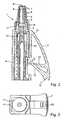
- a dosing device 1 after the Fig. 1 to 3is intended for the application of cosmetic media. In the same way, however, such a metering device can also be used for pharmaceutical purposes.
- the metering devicehas a metering housing 4, 5, 10, which has an application extension 5 in an upper area.
- the dosing housing 4, 5has a jacket-like enveloping body 4, on which a lever-like actuating member 2 is integrally formed in the manner described in more detail below.
- the actuator 2is by means of a solid-state joint 15 to the metering 4, 5, that is mounted on the enveloping body 4, elastically pivotable.
- a pump unit 10 to 12is arranged coaxially to a central longitudinal axis of the metering device 1, which is designed as a thrust piston pump.
- the pump unithas a fixedly connected to the metering 4, 5 and in particular the enveloping body 4 hollow cylinder portion 10 in which a piston portion 11 is arranged to be linearly displaceable.
- the piston portion 11is within a metering chamber 9 of the metering 4, 5 movable and is provided at its protruding from the metering chamber 9, rear portion with a linear guide member 12 having step-shaped profiles for stepwise linear movement of the piston portion 11.
- the application extension 5is hollow and forms an application chamber area on the inside.
- the metering chamber 9opens over into this application chamber area.
- Strömungsleitprofiltechniken 8are provided, which are aligned along the stroke direction of the piston portion 11.
- the internal flow-guiding profilings 8are provided within the application chamber with openings to the outside of the application extension 5.
- the flow axes of these openingsare aligned with a radial component to the stroke axis of the piston portion 11.
- the application extension 5has a substantially flat surface, which is aligned in a radial plane relative to the stroke axis of the piston section 11.
- Web-like flow guide surfaces 7are provided on the front end region of the application extension 5.
- a cap 3is mounted from a resilient plastic material, which extends like a hood over the entire application extension 5 and ends at an unspecified annular collar portion of the enveloping body 4.
- the elastic capIn the frontal area of the Application extension 5, the elastic cap on a relatively small material thickness, which increases steadily down to the envelope 4 towards. The elasticity of the cap 3 is reduced as the material thickness increases.
- the cap 3is held in an axially form-fitting manner by means of an inner annular shoulder 16 in a corresponding annular groove 17 on the application extension 5.
- the cap 3is mounted under elastic tension on the application extension 5.
- the cap 3In its thin-walled end cap area, which rests on the front end region of the application extension 5, the cap 3 is provided with a metering opening 6 designed as a spray nozzle.
- a jacket portion of the protective cap 3In the thin-walled upper Stirnkappen Scheme a jacket portion of the protective cap 3 is designed thin-walled and provided with an annular stepped shoulder. At the level of the stepped paragraph, the outwardly leading openings of the Strömungsleitprofiltechniken 8 of the application extension 5 are provided.
- the wall thickness of the end cap area and in particular of the shell portion of the cap 3is dimensioned so thin that when expanded under pressure liquid medium in the region of the openings of Strömungsleitprofiltechniken 8, the shell portion of the cap 3 is widened in the manner of a hose valve, so that the liquid medium to the flow guide 7 and can flow to the metering opening 6 in the region of the outside of the application extension 5.
- the cap 3has a seal collar, not specified in more detail, which optionally causes a seal downwards by means of an engagement in a corresponding annular groove on the outer circumference of the application extension 5. Therefore, the medium flowing out through the openings can only be conveyed upwards to the metering opening 6.
- the flow guide surfaces 7 and the metering opening 6are matched to one another in such a way that the medium flow undergoes a swirling action and is atomized at the metering opening 6.
- the metering opening 6thus represents an atomizer opening.
- the tab-like obliquely outwardly and downwardly projecting actuator 2is provided with a web-shaped thrust element 13 which is integrally formed in a lower end portion of the actuator 2 and in the unloaded state of the actuator 2 at an acute angle protrudes upward to the lifting axis of the piston portion 11 and inwardly.
- the thrust element 13has at its inner Stirnend Scheme a cam portion which is provided for engagement in the sawtooth-like profilings 12 of the linear guide member.
- the cam portionprotrudes at the front end region of the thrust element 13 toward the linear guide part.
- Diametrically opposite the front end region of the thrust element 13is provided with an unspecified support shoe, which protrudes nose-like to the actuator 2 out.
- a support member 14cooperates, which is formed integrally on the actuating member 2 above the thrust element 13.
- the support member 14also projects at an acute angle - relative to the unloaded state of the actuator 2 - to the stroke axis of the piston portion 11 inwardly.
- the support element 14With its inside end region, the support element 14 is arranged in the immediate vicinity of the support shoe of the push element 13. In the unloaded state, the thrust element 13 and the support element 14 protrude as shown Fig. 2 at an acute angle to each other.
- the support member 14serves to avoid a deflection of the thrust element 13 in an engagement in the sawtooth-like profilings 12 of the linear guide part. The support element 14 thus stabilizes the thrust element 13 upon engagement in one of the profilings 12 of the linear guide part.
- the actuator 2is made of his in Fig. 2 represented, unloaded starting position by the fingers of one hand to the enveloping body 4 and thus pressed inwards. This gets the support cam of the push element 13 in engagement with one of the sawtooth profilings 12 of the linear guide part. In a further Nachinnenschwenken the actuator 2, a linear movement is inevitably exerted on the linear guide part upwards.
- the support element 14is provided for stabilizing the latched or hooked push position of the pusher element 13, ie the support cam, which in the depressed state of the actuator 2 due to certain elastic Deformations of the thrust element and the actuator 2, the support shoe engages behind stabilizing.
- the elastic tension of the actuator 2causes a provision in the in Fig. 2 illustrated starting position.
- the support camagain disengaged from the linear guide part.
- the linear guide part and thus also the piston portion 11remain in the set during the actuation stroke position.
- a stop extension 18is integrally formed, on the one hand forms an end stop for the actuator 2 and, secondly, a bearing surface for a safe installation of the metering device 1 in the upright state in addition to the footprint in the region of a bottom of the envelope 4 offers.
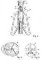
- the metering device 1ahas two diametrically opposed, wing-like actuators 2a, which are each provided with obliquely inwardly and upwardly projecting pushers 13a.
- the two actuators 2aprotrude from an unspecified ring body in one piece, which rests on a collar of a metering 4a.
- the ring bodyforms an enveloping body.
- the metering housing 4aforms in its interior a substantially cylindrical metering chamber, in which a piston 11a of a pump unit is slidably disposed.
- the piston 11ahas at its end facing away from the dosing chamber sawtooth-like profiling, which belong to a linear guide part.
- the actuators 2aare according to the embodiment of the Fig.
- a pressure load from the outside on the actuators 2acauses via the thrust elements 13a analogous to the embodiment described above, a lifting movement of the piston 11a.
- the pressure load on both actuators 2atakes place simultaneously and uniformly, so that both thrust elements 13a simultaneously exert the same pressure loads in the stroke direction on the piston 11a.
- the actuators 2amove back to its unloaded starting position, whereby the pushers 13a are inevitably moved relative to the linear guide member in the direction of lying below profilings. With a renewed load on the actuators 2a an attack of the thrust elements 13a takes place at the corresponding lower lying, sawtooth-like profilings.
- the metering housing 4ais provided with an application extension 5a, which encloses a hemispherical application chamber.
- an application extension 5awhich encloses a hemispherical application chamber.
- the application chamberis filled by a spherical filling body 21 which is matched to the dimensions of the application chamber in such a way that the filling body 21 is held in an interference fit within this application chamber ( Fig. 4 ).
- the liquid medium from the metering chambercan thus be conveyed only via the flow grooves 19 past the filling body 21 to the metering opening 20.
- the metering opening 20is designed as a spray nozzle, so that, with the aid of the swirl functions of the mouth regions of the flow grooves 19, good atomization of the liquid medium is achieved on exiting outward.
- the metering device 1ais provided in particular for cosmetic purposes.
- the metering opening 20is closed by a tear-off cap 22, which is hat-shaped and consequently forms an upwardly open hollow chamber 23 in the molded-on state.
- the hollow chamber 23is matched to the outer contour of the application extension 5a, so that the tear-off cap 22 can be attached to the application extension 5a after being torn off in the inverted state, thus causing a detachable closure of the metering opening 20.
- the dosing device 1bhas an application extension 5b, which is likewise provided with a molded-on tear-off cap 22b. After tearing off the tear-off cap 22b, it can be turned over and placed on the application extension 5b as a detachable closure.
- the enveloping body 4bitself has diametrically opposite two lug-shaped actuating members 2b, which are integrated flush in the contour of the enveloping body 4b and are otherwise integrally formed with the enveloping body 4b.
- the mobility of the tab-like actuators 2bis achieved in that each actuator 2b are cut free by two respective slots, which are open to a lower edge region of the envelope 4b.
- Both actuators 2bare analogous to the illustration Fig. 4
- On the inside thrust elementswhich are in operative connection with a corresponding linear guide part of the pump unit.
Landscapes
- Containers And Packaging Bodies Having A Special Means To Remove Contents (AREA)
- Coating Apparatus (AREA)
- Fluid-Pressure Circuits (AREA)
- Vehicle Body Suspensions (AREA)
- Body Structure For Vehicles (AREA)
Abstract
Description
Translated fromGermanDie Erfindung betrifft eine Dosiervorrichtung mit einem ein- oder mehrteiligen Dosiergehäuse, dem eine Pumpeinheit sowie eine manuell bedienbare Betätigungseinheit zugeordnet sind, wobei das Dosiergehäuse wenigstens eine Dosieröffnung umfasst.The invention relates to a metering device with a one-part or multi-part metering housing, to which a pump unit and a manually operable actuating unit are assigned, wherein the metering housing comprises at least one metering opening.
Derartige Dosiervorrichtungen sind zur Ausbringung von pharmazeutischen oder kosmetischen Medien allgemein bekannt. Eine solche Dosiervorrichtung weist ein Dosiergehäuse auf, das aus Kunststoff hergestellt ist. Das Dosiergehäuse umfasst eine Schraubkappe, die auf einen Mediumbehälter aufschraubbar ist. Konzentrisch innerhalb des Dosiergehäuses ist eine Pumpeinheit angeordnet, die als mechanisch betätigbare Schubkolbenpumpe ausgeführt ist. Zur Betätigung der Schubkolbenpumpe ist eine Betätigungseinheit vorgesehen, die mit dem hubbeweglichen Teil der Pumpeinheit verbunden ist und eine Fingerauflage für eine manuelle Betätigung der Pumpeinheit umfasst. Das Dosiergehäuse ist mit einem Applikationsfortsatz, insbesondere in Form eines Sprühkopfes oder in Form einer Nasenolive, versehen. In dem Applikationsfortsatz, der Teil des Dosiergehäuses ist, ist wenigstens eine Dosieröffnung vorgesehen, mittels der das insbesondere flüssige Medium von der Pumpeinheit über wenigstens einen Austragkanal in die Umgebung ausbringbar ist.Such metering devices are well known for the application of pharmaceutical or cosmetic media. Such a metering device has a Dosiergehäuse, which is made of plastic. The metering housing comprises a screw cap which can be screwed onto a medium container. Concentrically within the metering a pump unit is arranged, which is designed as a mechanically actuated thrust piston pump. For actuating the thrust piston pump, an actuating unit is provided, which is connected to the liftable part of the pump unit and a finger rest for a manual operation of the pump unit comprises. The metering housing is provided with an application extension, in particular in the form of a spray head or in the form of a nose olive. In the application extension, which is part of the metering, at least one metering opening is provided, by means of which the particular liquid medium from the pump unit via at least one discharge channel in the environment can be discharged.
Dokument
Aufgabe der Erfindung ist es, eine Dosiervorrichtung der eingangs genannten Art zu schaffen, die mit einfachen Mitteln einen guten Mediumaustrag ermöglicht.The object of the invention is to provide a metering device of the type mentioned, which allows a simple medium discharge a good medium.
Diese Aufgabe wird dadurch gelöst, dass das Dosiergehäuse einen die Pumpeinheit ummantelnden Hüllkörper aufweist, an dem wenigstens ein zwischen einer Ruhestellung und einer Betätigungsstellung elastisch schwenkbeweglich gelagertes Betätigungsglied einstückig angeformt ist. Der Hüllkörper bildet zum einen eine Ummantelung der Dosiervorrichtung. Zum anderen dient er zur Anordnung des Betätigungsgliedes. Die einstückige Anformung des Betätigungsgliedes ermöglicht einen äußerst einfachen Aufbau der Dosiervorrichtung mit wenigen Bauteilen. Vorzugsweise ist das Dosiergehäuse einschließlich des Hüllkörpers und des Betätigungsgliedes aus Kunststoff hergestellt. Hierdurch sind kostengünstig Dosiervorrichtungen in hohen Stückzahlen herstellbar.This object is achieved in that the metering housing has a casing body enclosing the pumping unit, on which at least one actuating member elastically pivotably mounted between a rest position and an actuating position is integrally formed. The enveloping body forms on the one hand a casing of the metering device. On the other hand it serves to arrange the actuator. The integral molding of the actuator allows a very simple construction of the metering device with few components. Preferably, the Dosiergehäuse including the envelope body and the actuator is made of plastic. As a result, metering devices can be produced cost-effectively in high quantities.
In Ausgestaltung der Erfindung ist die Dosieröffnung einem Applikationsfortsatz des Dosiergehäuses zugeordnet, und auf den Applikationsfortsatz ist eine Kappe aus elastischem Schlauchmaterial aufgezogen, die mit der Dosieröffnung versehen ist. Die Kappe wird unter Spannung aufgezogen und ist somit im wesentlichen kraftschlüssig auf dem Applikationsfortsatz gehalten. Da die Kappe ein separates Bauteil ist, ist es möglich, unterschiedliche Arten von Dosieröffnungen bei verschiedenen Kappen vorzusehen, so dass die jeweils geeignete Kappe modulartig auf den Applikationsfortsatz aufziehbar ist.In an embodiment of the invention, the metering orifice is associated with an application extension of the metering housing, and a cap made of elastic tubing, which is provided with the metering opening, is mounted on the application extension. The cap is mounted under tension and is thus held substantially non-positively on the application extension. Since the cap is a separate component, it is possible to provide different types of metering orifices with different caps, so that the respectively suitable cap can be pulled onto the application extension in a modular manner.
In weiterer Ausgestaltung der Erfindung ist der Applikationsfortsatz mit wenigstens abschnittsweise außen liegenden Strömungsleitflächen versehen, und die Kappe ist wenigstens in einem Teilabschnitt als mit den Strömungsleitflächen zusammenwirkendes Schlauchventil ausgebildet. Die Kappe weist hierdurch eine Doppelfunktion auf, da sie neben der Dosier- oder Ausbringcharakteristik auch eine Ventilfunktion übernimmt.In a further embodiment of the invention, the application extension is provided with at least partially outer flow guide surfaces, and the cap is formed at least in a partial section as cooperating with the flow guide tube valve. The cap thus has a dual function, since it also assumes a valve function in addition to the metering or Ausbringcharakteristik.
In weiterer Ausgestaltung der Erfindung weist die elastische Kappe wenigstens eine Ringprofilierung auf, die im montierten Zustand formschlüssig mit einer korrespondierenden Ringprofilierung des Applikationsfortsatzes zusammenwirkt. Diese Ringprofilierung verhindert, dass die Kappe durch Druckbeaufschlagung der Pumpeinheit insbesondere in ihrem Funktionszustand als Schlauchventil sich von dem Applikationsfortsatz löst oder ihre Position auf dem Applikationsfortsatz verändert.In a further embodiment of the invention, the elastic cap has at least one annular profiling, which cooperates positively in the mounted state with a corresponding ring profiling of the application extension. This annular profiling prevents the cap from being released from the application extension or changing its position on the application extension by pressurization of the pump unit, in particular in its functional state as a hose valve.
In weiterer Ausgestaltung der Erfindung ist das Betätigungsglied hebelartig an dem Hüllkörper gelagert und weist an seinem freien Stirnendbereich ein bei einem Betätigungshub mit einem Linearführungsteil der Pumpeinheit in Wirkverbindung stehendes Schubelement auf. Dadurch wird eine Schwenkbewegung des Betätigungsgliedes in einen Betätigungshub der Pumpeinheit übertragen. Besonders vorteilhaft ist das Schubelement einstückig an dem Betätigungsglied angeformt. Hierdurch wird eine weitere Vereinfachung der Herstellung der Dosiervorrichtung erreicht.In a further embodiment of the invention, the actuating member is mounted lever-like manner on the enveloping body and has at its free Stirnendbereich a in an operating stroke with a linear guide part of the pump unit operatively connected thrust element. As a result, a pivoting movement of the actuating member is transferred into an actuating stroke of the pumping unit. Particularly advantageously, the push element is integrally formed on the actuator. This achieves a further simplification of the production of the metering device.
In weiterer Ausgestaltung der Erfindung ist dem Schubelement ein Stützelement zugeordnet, das das Schubelement bei einem Angriff an dem Linearführungsteil mechanisch stabilisiert. Hierdurch wird gewährleistet, dass eine exakte Hubdosierung bei einer Betätigung des hebelartigen Betätigungsgliedes erreicht wird. Elastische Deformationen, insbesondere Biegungen des Schubelementes, werden durch das Stützelement verhindert.In a further embodiment of the invention, the thrust element is associated with a support element which mechanically stabilizes the thrust element in an attack on the linear guide part. This ensures that an exact Hubdosierung is achieved upon actuation of the lever-like actuator. Elastic deformations, in particular bends of the thrust element, are prevented by the support element.
In weiterer Ausgestaltung der Erfindung ist das Stützelement einstückig an dem Betätigungsglied angeformt. Hierdurch wird mit besonders einfachen Mitteln eine sichere Stabilisierung des Schubelementes bei einer Bewegung des Betätigungsgliedes erreicht.In a further embodiment of the invention, the support element is integrally formed on the actuating member. As a result, a secure stabilization of the thrust element is achieved with a movement of the actuator with particularly simple means.
In weiterer Ausgestaltung der Erfindung ist das Stützelement in Abstand zu dem Schubelement angeordnet und als Begrenzungsanschlag für eine elastische Deformation des Schubelementes ausgebildet. Das Stützelement stützt und stabilisiert das Schubelement so, dass eine sichere und gleichbleibende Wirkverbindung mit dem Linearführungsteil der Pumpeinheit erreicht wird.In a further embodiment of the invention, the support element is arranged at a distance from the thrust element and designed as a limit stop for an elastic deformation of the thrust element. The support element supports and stabilizes the push element so that a secure and consistent operative connection with the linear guide part of the pump unit is achieved.
In weiterer Ausgestaltung der Erfindung ist in einem Applikationsfortsatz des Dosiergehäuses eine halbkugelförmige Dosierkammer vorgesehen, die mit mehreren Strömungsleitprofilierungen in ihrem Wandungsbereich versehen ist, die an der Dosieröffnung münden, und die Dosierkammer ist mit einem kugelförmigen Füllkörper versehen, der auf die Halbkugelform der Dosierkammer abgestimmt ist. Dadurch ist eine besonders gute Strömungsführung für das auszubringende Medium erreichbar.In a further embodiment of the invention, a hemispherical metering chamber is provided in an application extension of the metering housing, which is provided with several Strömungsleitprofilierungen in its wall region, which open at the metering, and the metering chamber is provided with a spherical packing, which is tuned to the hemispherical shape of the metering chamber. As a result, a particularly good flow guidance for the auszubringende medium can be achieved.
In weiterer Ausgestaltung der Erfindung ist der Applikationsfortsatz des Dosiergehäuses mit einer im Bereich der Dosieröffnung angeformten Abreißkappe versehen, die im abgerissenen Zustand als Verschlusskappe für den Applikationsfortsatz und die Dosieröffnung vorgesehen ist. Die Abreißkappe weist somit eine Doppelfunktion auf, da sie zum einen im noch nicht abgerissenen Ursprungszustand die Dosieröffnung verschließt und zum anderen auch im abgerissenen Zustand so auf den Applikationsfortsatz aufsetzbar ist, dass eine Abdichtung der Dosieröffnung erreicht wird. Vorzugsweise ist die Abreißkappe auf ihrer dem Abreißnippel gegenüberliegenden Seite mit einem offenen Hohlraum versehen, der auf die Außenkontur des Applikationsfortsatzes abgestimmt ist und so ein kraftschlüssiges Aufdrücken der Abreißkappe auf den Applikationsfortsatz ermöglicht.In a further embodiment of the invention, the application extension of the metering housing is provided with a tear-off cap formed in the region of the metering opening, which in the torn-off state is provided as a closure cap for the application extension and the metering opening. The tear-off cap thus has a dual function, since it closes the metering opening in the original state, which has not yet been torn off, and can also be placed on the application extension in the torn-off state in such a way that a sealing of the metering opening is achieved. Preferably, the tear-off is provided on its side opposite the Abreißnippel side with an open cavity, which is tuned to the outer contour of the application extension and thus allows a force-locking pressing the tear-off on the application extension.
In weiterer Ausgestaltung der Erfindung ist als Betätigungsglied eine Betätigungslasche vorgesehen, die bündig in der Hüllfläche des Hüllkörpers integriert und durch Schlitze in dem Hüllkörper für eine Schwenkbeweglichkeit freigeschnitten ist. Dadurch wird in ästhetisch ansprechender und platzsparender Weise eine Betätigungsfunktion für die Dosiervorrichtung erzielt. Vorzugsweise sind zwei Betätigungslaschen auf gegenüberliegenden Seiten des Hüllkörpers in diesem integriert.In a further embodiment of the invention, an actuating tab is provided as an actuator, which is integrated flush in the envelope surface of the envelope body and is cut free by slots in the enveloping body for a pivoting movement. As a result, an actuation function for the metering device is achieved in aesthetically pleasing and space-saving manner. Preferably, two actuating tabs are integrated on opposite sides of the enveloping body in this.
Weitere Vorteile und Merkmale der Erfindung ergeben sich aus den Ansprüchen sowie aus der nachfolgenden Beschreibung bevorzugter Ausführungsbeispiele der Erfindung, die anhand der Zeichnungen dargestellt sind.
- Fig. 1
- zeigt in einer Seitenansicht eine Ausführungsform einer erfin- dungsgemäßen Dosiervorrichtung,
- Fig. 2
- die Dosiervorrichtung nach
Fig. 1 in einer Schnittdarstellung ent- lang der Schnittlinie II-II inFig. 1 , - Fig. 3
- eine Ansicht der Dosiervorrichtung nach den
Fig. 1 und2 von unten, - Fig. 4
- in einer Schnittdarstellung die Ausführungsform einer Dosiervorrichtung, die nicht Teil der vorliegenden Erfindung ist,
- Fig. 5
- in vergrößerter Darstellung eine Ansicht von unten auf einen Stirnbereich eines Dosiergehäuses der Dosiervorrichtung nach
Fig. 4 auf Höhe einer Dosieröffnung, - Fig. 6
- in vergrößerter Schnittdarstellung einen Ausschnitt des Stirnbe- reiches des Dosiergehäuses auf Höhe der Dosieröffnung und
- Fig. 7
- in perspektivischer Darstellung die Auführungsform einer Dosiervorrichtung, die nicht Teil der vorliegenden Erfindung ist.
- Fig. 1
- shows a side view of an embodiment of a metering device according to the invention,
- Fig. 2
- the metering device after
Fig. 1 in a sectional view along the section line II-II inFig. 1 . - Fig. 3
- a view of the metering device according to the
Fig. 1 and2 from underneath, - Fig. 4
- in a sectional view of the embodiment of a metering device, which is not part of the present invention,
- Fig. 5
- in an enlarged view of a bottom view of a front portion of a metering of the metering device according to
Fig. 4 at the height of a metering opening, - Fig. 6
- in enlarged sectional view a section of the front region of the metering housing at the level of the metering opening and
- Fig. 7
- in perspective view of the Auführungsform a dosing device, which is not part of the present invention.
Eine Dosiervorrichtung 1 nach den
In dem Dosiergehäuse 4, 5 ist eine Pumpeinheit 10 bis 12 koaxial zu einer Mittellängsachse der Dosiervorrichtung 1 angeordnet, die als Schubkolbenpumpe ausgeführt ist. Die Pumpeinheit weist einen fest mit dem Dosiergehäuse 4, 5 und insbesondere dem Hüllkörper 4 verbundenen Hohlzylinderabschnitt 10 auf, in dem ein Kolbenabschnitt 11 linearbeweglich verschiebbar angeordnet ist. Der Kolbenabschnitt 11 ist innerhalb einer Dosierkammer 9 des Dosiergehäuses 4, 5 beweglich und ist an seinem aus der Dosierkammer 9 herausragenden, rückwärtigen Bereich mit einem Linearführungsteil 12 versehen, der stufenförmige Profilierungen zum schrittweisen Linearbewegen des Kolbenabschnittes 11 aufweist.In the
Der Applikationsfortsatz 5 ist hohl gestaltet und bildet innenseitig einen Applikationskammerbereich. Die Dosierkammer 9 geht offen in diesen Applikationskammerbereich über. In dem Applikationskammerbereich sind Strömungsleitprofilierungen 8 vorgesehen, die längs der Hubrichtung des Kolbenabschnittes 11 ausgerichtet sind. In einem oberen Bereich des Applikationsfortsatzes sind die innenliegenden Strömungsleitprofilierungen 8 innerhalb der Applikationskammer mit Öffnungen zur Außenseite des Applikationsfortsatzes 5 hin versehen. Die Strömungsachsen dieser Öffnungen sind mit einer Radialkomponente zu der Hubachse des Kolbenabschnittes 11 ausgerichtet. In einem oberen Stirnflächenbereich weist der Applikationsfortsatz 5 eine im wesentlichen ebene Fläche auf, die in einer Radialebene relativ zu der Hubachse des Kolbenabschnittes 11 ausgerichtet ist. Auf dem Stirnendbereich des Applikationsfortsatzes 5 sind stegartige Strömungsleitflächen 7 vorgesehen.The
Auf den Applikationsfortsatz 5 ist eine Kappe 3 aus einem elastischen Kunststoffmaterial aufgezogen, die sich haubenartig über den gesamten Applikationsfortsatz 5 erstreckt und an einem nicht näher bezeichneten Ringbundabschnitt des Hüllkörpers 4 endet. In dem Stirnendbereich des Applikationsfortsatzes 5 weist die elastische Kappe eine relativ geringe Materialstärke auf, die sich nach unten zum Hüllkörper 4 hin stetig erhöht. Mit der Erhöhung der Materialstärke reduziert sich die elastische Nachgiebigkeit der Kappe 3. Die Kappe 3 ist mittels einer innenliegenden Ringschulter 16 in einer korrespondierenden Ringnut 17 an dem Applikationsfortsatz 5 axial formschlüssig gehalten. Zudem ist die Kappe 3 unter elastischer Spannung auf den Applikationsfortsatz 5 aufgezogen. In ihrem dünnwandigen Stirnkappenbereich, der auf dem Stirnendbereich des Applikationsfortsatzes 5 aufliegt, ist die Kappe 3 mit einer als Sprühdüse ausgebildeten Dosieröffnung 6 versehen. In dem dünnwandigen oberen Stirnkappenbereich ist ein Mantelabschnitt der Schutzkappe 3 dünnwandig gestaltet und mit einem ringförmigen Stufenabsatz versehen. Auf Höhe des Stufenabsatzes sind die nach außen führenden Öffnungen der Strömungsleitprofilierungen 8 des Applikationsfortsatzes 5 vorgesehen. Die Wandstärke des Stirnkappenbereiches und insbesondere des Mantelabschnittes der Kappe 3 ist so dünn bemessen, dass bei unter Druck ausströmendem flüssigem Medium im Bereich der Öffnungen der Strömungsleitprofilierungen 8 der Mantelabschnitt der Kappe 3 nach Art eines Schlauchventils aufgeweitet wird, so dass das flüssige Medium zu den Strömungsleitflächen 7 und zu der Dosieröffnung 6 im Bereich der Außenseite des Applikationsfortsatzes 5 strömen kann. Knapp unterhalb der nach außen tretenden Öffnungen in dem Applikationsfortsatz 5 weist die Kappe 3 einen nicht näher bezeichneten Dichtbund auf, der gegebenenfalls mittels eines Eingriffes in eine entsprechende Ringnut am Außenumfang des Applikationsfortsatzes 5 eine Abdichtung nach unten bewirkt. Das durch die Öffnungen ausströmende Medium kann daher lediglich nach oben zur Dosieröffnung 6 hin gefördert werden. Die Strömungsleitflächen 7 und die Dosieröffnung 6 sind derart aufeinander abgestimmt, dass die Mediumströmung eine Drallgebung erfährt und an der Dosieröffnung 6 zerstäubt wird. Die Dosieröffnung 6 stellt somit eine Zerstäuberöffnung dar.On the
Um eine Pumpbewegung des Kolbenabschnittes 11 zu erzielen, ist das laschenartig schräg nach außen und nach unten abstehende Betätigungsglied 2 mit einem stegförmigen Schubelement 13 versehen, das einstückig in einem unteren Endbereich des Betätigungsgliedes 2 angeformt ist und im unbelasteten Zustand des Betätigungsgliedes 2 in einem spitzen Winkel zur Hubachse des Kolbenabschnittes 11 nach oben und nach innen abragt. Das Schubelement 13 weist an seinem inneren Stirnendbereich einen Nockenabschnitt auf, der für einen Eingriff in die sägezahnartigen Profilierungen 12 des Linearführungsteiles vorgesehen ist. Der Nockenabschnitt ragt an dem Stirnendbereich des Schubelementes 13 zu dem Linearführungsteil hin ab. Diametral gegenüberliegend ist der Stirnendbereich des Schubelementes 13 mit einem nicht näher bezeichneten Stützschuh versehen, der nasenartig zum Betätigungsglied 2 hin abragt. Mit dem nasenartigen Stützschuh wirkt ein Stützelement 14 zusammen, das oberhalb des Schubelementes 13 einstückig an dem Betätigungsglied 2 angeformt ist. Das Stützelement 14 ragt ebenfalls in einem spitzen Winkel - auf den unbelasteten Zustand des Betätigungsgliedes 2 bezogen - zu der Hubachse des Kolbenabschnittes 11 nach innen ab. Mit seinem innen liegenden Stirnbereich ist das Stützelement 14 in unmittelbarer Nähe zu dem Stützschuh des Schubelementes 13 angeordnet. Im unbelasteten Zustand ragen das Schubelement 13 und das Stützelement 14 gemäß der Darstellung nach
Um einen Betätigungshub für die Dosiervorrichtung 1 durchzuführen, wird das Betätigungsglied 2 aus seiner in
In einem unteren Bereich des Schubelementes 13 ist ein Anschlagfortsatz 18 einstückig angeformt, der zum einen einen Endanschlag für das Betätigungsglied 2 bildet und zum anderen eine Auflagefläche für ein sicheres Aufstellen der Dosiervorrichtung 1 in aufrechtem Zustand zusätzlich zu der Standfläche im Bereich eines Bodens des Hüllkörpers 4 bietet.In a lower region of the
Bei der Ausführungsform nach den
In einem oberen Bereich ist das Dosiergehäuse 4a mit einem Applikationsfortsatz 5a versehen, der eine halbkugelartige Applikationskammer umschließt. In der Wandung der Applikationskammer sind insgesamt drei Strömungsleitprofilierungen in Form von Strömungsnuten 19 vorgesehen, die tangential in eine ringförmige Dosieröffnung 20 münden und so eine Drallgebung bewirken. Die Applikationskammer ist durch einen kugelförmigen Füllkörper 21 ausgefüllt, der derart auf die Abmessungen der Applikationskammer abgestimmt ist, dass der Füllkörper 21 im Presssitz innerhalb dieser Applikationskammer gehalten ist (
Im unbenutzten Zustand ist die Dosieröffnung 20 durch eine Abreißkappe 22 verschlossen, die hutförmig ausgebildet ist und demzufolge eine im angespritzten Zustand nach oben offene Hohlkammer 23 bildet. Die Hohlkammer 23 ist auf die Außenkontur des Applikationsfortsatzes 5a abgestimmt, so dass die Abreißkappe 22 nach dem Abreißen in umgedrehtem Zustand auf den Applikationsfortsatz 5a aufsteckbar ist und so einen lösbaren Verschluss der Dosieröffnung 20 bewirkt.In the unused state, the
Bei der Ausführungsform nach
Claims (8)
- Dosing device with a one-part of multi-part dosing housing with which are associated a pump unit and a manually operable actuating unit, where the dosing housing comprises at least one dosing orifice, where the dosing orifice (6, 20) is associated with an application extension of the dosing housing and a cap (3) of elastic plastic material is slid onto the application extension (5) and is provided with the dosing orifice (6),characterized in that- the application extension (5) is provided with flow guide surfaces positioned at least in some sections of the exterior and the cap (3) is designed at last in one partial section as a tube valve interacting with the flow guide surfaces and- the application extension (5) is designed hollow and forms an inside application chamber area which is connected via orifices to an area between the application extension (5) and the cap (3).
- Dosing device according to Claim 1,characterized in that the elastic cap (3) has at least one annular profile (16) which in the fitted state interacts positively with a corresponding annular profile (17) of the application extension (5).
- Dosing device according to Claim 1,characterized in that the actuator (2) is mounted lever-like on the casing body and has at its free end face area a pusher element (13) in operative connection with a linear guide part of the pump unit during an actuation stroke.
- Dosing device according to Claim 3,characterized in that the pusher element (13) is cast in one piece with the actuator (2).
- Dosing device according to Claim 4,characterized in that a support element (14) is associated with the pusher element (13) and mechanically stabilizes the pusher element (13) when it acts on the linear guide part.
- Dosing device according to Claim 5,characterized in that the support element (14) is cast in one piece with the actuator (2).
- Dosing device according to Claim 5,characterized in that the pusher element (13) acts at an acute angle relative to the linear guide part (12) when seen in the pump direction.
- Dosing device according to Claim 7,characterized in that the support element (14) is arranged at a distance from the pusher element (13) and is designed as a limiting stop for an elastic deformation of the pusher element (13).
Applications Claiming Priority (2)
| Application Number | Priority Date | Filing Date | Title |
|---|---|---|---|
| DE10343329ADE10343329A1 (en) | 2003-09-11 | 2003-09-11 | Dosing device with a single or multi-part dosing |
| DE10343329 | 2003-09-11 |
Publications (2)
| Publication Number | Publication Date |
|---|---|
| EP1514608A1 EP1514608A1 (en) | 2005-03-16 |
| EP1514608B1true EP1514608B1 (en) | 2011-01-05 |
Family
ID=34129827
Family Applications (1)
| Application Number | Title | Priority Date | Filing Date |
|---|---|---|---|
| EP04019341AExpired - LifetimeEP1514608B1 (en) | 2003-09-11 | 2004-08-14 | Dosing device comprising an elastic actuator |
Country Status (4)
| Country | Link |
|---|---|
| US (1) | US7571838B2 (en) |
| EP (1) | EP1514608B1 (en) |
| AT (1) | ATE494074T1 (en) |
| DE (2) | DE10343329A1 (en) |
Families Citing this family (9)
| Publication number | Priority date | Publication date | Assignee | Title |
|---|---|---|---|---|
| EP1714667A1 (en)* | 2005-04-20 | 2006-10-25 | Medisize Schweiz AG | Dosing system with dripper or spray and two articulated arms and method of fabrication |
| SE529956C2 (en)* | 2005-07-12 | 2008-01-15 | Medux Ab | Spraying device, method of spraying and method of manufacture of device |
| WO2007108768A1 (en)* | 2006-03-20 | 2007-09-27 | Doxa Ab | Mixing and injection system for injectable biomaterials or artificial materials in orthopaedic applications |
| FR2913341B1 (en)* | 2007-03-07 | 2009-11-20 | Primequal Sa | DEVICE FOR DISPOSABLE EJECTION OF A LIQUID OR PASTY PRODUCT |
| USD648622S1 (en)* | 2008-06-03 | 2011-11-15 | Kisling Ag | Dosing device |
| DE102009013968A1 (en)* | 2009-03-19 | 2010-09-23 | Fischerwerke Gmbh & Co. Kg | syringe |
| DE102016114405A1 (en)* | 2016-03-23 | 2017-09-28 | F+K lnnovationen GmbH & Co. KG | Kartuschentropfendosierer |
| DE102018117731A1 (en)* | 2018-01-16 | 2019-07-18 | F+K Innovationen Gmbh & Co. Kg | Device for dosing liquid |
| FR3088224B1 (en)* | 2018-11-14 | 2023-01-13 | Aptar France Sas | FLUID PRODUCT DISTRIBUTION DEVICE. |
Family Cites Families (23)
| Publication number | Priority date | Publication date | Assignee | Title |
|---|---|---|---|---|
| US3204835A (en)* | 1962-12-04 | 1965-09-07 | American Can Co | Tube structure |
| US3161325A (en)* | 1963-06-19 | 1964-12-15 | Lester H Hinkel | Expulsion device |
| FR1430243A (en)* | 1965-01-07 | 1966-03-04 | Improvements to vaporizers, especially for perfumery | |
| US3437270A (en)* | 1968-03-12 | 1969-04-08 | Risdon Mfg Co | Self-sealing spray-actuator button |
| CA1077001A (en)* | 1976-10-21 | 1980-05-06 | Winfried J. Werding | Appliance for discharging gaseous liquid or pasty product, and process of its manufacture |
| DE7817873U1 (en)* | 1978-06-15 | 1978-09-28 | Teroson Gmbh, 6900 Heidelberg | Gun for connection with cartridges |
| US4187985A (en)* | 1978-12-08 | 1980-02-12 | The Continental Group, Inc. | Aerosol valve for barrier type packages |
| US4360156A (en)* | 1980-05-27 | 1982-11-23 | Delavan Corporation | Fluid metering and spraying |
| US4323176A (en)* | 1980-07-11 | 1982-04-06 | Taco Bell | Manually-operable ratchet type dispenser for comestibles |
| DE8701486U1 (en)* | 1987-01-30 | 1988-06-01 | Espe Stiftung & Co Produktions- und Vertriebs KG, 8031 Seefeld | Dosing device |
| FR2656854B2 (en)* | 1989-02-24 | 1994-11-25 | Raoul Laffy | CONTAINER OR ASEPTIC CONTAINER FOR A NON-PASTY PRODUCT. |
| FR2699835B1 (en)* | 1992-12-28 | 1995-03-31 | Oreal | Kit for spraying a liquid comprising a precompression pump. |
| US5647515A (en)* | 1995-09-29 | 1997-07-15 | Zwijnenberg; Lambertus Herman | Stepping plunger for air-activated dispensing system |
| CA2269551C (en)* | 1996-10-18 | 2007-03-06 | Wheaton Holding, Inc. | Container closure assembly |
| DE19749514A1 (en) | 1997-11-08 | 1999-05-12 | Pfeiffer Erich Gmbh & Co Kg | Delivery of a mixture of media for e.g. pharmaceutical products |
| DE19756442A1 (en)* | 1997-12-18 | 1999-06-24 | Pfeiffer Erich Gmbh & Co Kg | Media Donor |
| FR2781772B1 (en)* | 1998-07-31 | 2000-10-13 | Sofab | DISPENSER OF LIQUID PRODUCTS FOR DELIVERY BY SPRAYING |
| DE19937442A1 (en)* | 1999-08-07 | 2001-02-08 | Pfeiffer Erich Gmbh & Co Kg | Dispenser for flowable media, in particular for atomizing liquids |
| ES2238450T3 (en)* | 2000-06-07 | 2005-09-01 | LOCTITE (R & D) LIMITED | DISPENSER PACKING THAT INCLUDES A NOZZLE ASSEMBLY WITH A REUSABLE REMOVABLE PLUG AND COMBINED PACKAGING. |
| FR2813592B1 (en)* | 2000-09-07 | 2003-03-21 | Valois Sa | DEVICE FOR DISPENSING A FLUID PRODUCT OF THE SINGLE OR TWO DOSE TYPE |
| US6543703B2 (en)* | 2000-12-26 | 2003-04-08 | William S. Blake | Flexible face non-clogging actuator assembly |
| FR2830519B1 (en)* | 2001-10-04 | 2004-08-27 | Valois Sa | SIDE-OPERATED FLUID PRODUCT DISPENSING DEVICE |
| FR2834920B1 (en)* | 2002-01-22 | 2004-04-09 | Valois Sa | SIDE OPERATION SPRAYING DEVICE |
- 2003
- 2003-09-11DEDE10343329Apatent/DE10343329A1/ennot_activeWithdrawn
- 2004
- 2004-08-14EPEP04019341Apatent/EP1514608B1/ennot_activeExpired - Lifetime
- 2004-08-14ATAT04019341Tpatent/ATE494074T1/enactive
- 2004-08-14DEDE502004012082Tpatent/DE502004012082D1/ennot_activeExpired - Lifetime
- 2004-09-10USUS10/938,065patent/US7571838B2/ennot_activeExpired - Fee Related
Also Published As
| Publication number | Publication date |
|---|---|
| ATE494074T1 (en) | 2011-01-15 |
| US20050056664A1 (en) | 2005-03-17 |
| US7571838B2 (en) | 2009-08-11 |
| DE502004012082D1 (en) | 2011-02-17 |
| EP1514608A1 (en) | 2005-03-16 |
| DE10343329A1 (en) | 2005-04-07 |
Similar Documents
| Publication | Publication Date | Title |
|---|---|---|
| DE60035828T2 (en) | Discharge valve device for a lever-operated spray device | |
| EP2018228B1 (en) | Dispensing device | |
| DE69409380T2 (en) | SPRAY NOZZLE AND SPRAYER WITH SUCH A NOZZLE | |
| DE60204988T2 (en) | SPRAYING DEVICE WITH LATERAL ACTUATION | |
| DE4102506C2 (en) | Discharge device for media | |
| DE69803361T2 (en) | DEVICE FOR DELIVERING THE FLOWABLE PRODUCT WITH LOCKING DEVICE | |
| EP0312722B1 (en) | Dosing and spraying pump for liquid viscous products | |
| EP2018227B1 (en) | Dispensing device | |
| DE69503369T2 (en) | PUMP WITH PRESSURE PRESSURE | |
| EP2164645B1 (en) | Dispenser for dispensing liquid or pasty materials | |
| WO2003026803A1 (en) | Dosing device with a pump device | |
| DE1482675A1 (en) | Dispenser for liquids | |
| DE3315334A1 (en) | SPRAYER OR DOSING PUMP | |
| DE3631341A1 (en) | Discharging device for free-flowing media | |
| EP1477233A2 (en) | Fluid dispenser | |
| EP0882516A1 (en) | Fluid dispenser | |
| EP1375011B1 (en) | Dosing apparatus for at least one fluid | |
| DE69500443T2 (en) | Manually operated pump with pre-pressure chamber for atomizing a liquid and dispenser with such a pump | |
| DE20110604U1 (en) | Dispenser for pasty product | |
| DE20201742U1 (en) | Dispenser for flowable products | |
| DE19739989A1 (en) | Media Donor | |
| EP1295645B1 (en) | Metering device provided with a pump | |
| EP1514608B1 (en) | Dosing device comprising an elastic actuator | |
| DE3828811A1 (en) | Metering and spraying pump for liquid and low-viscosity substances | |
| DE10015968A1 (en) | Media Donor |
Legal Events
| Date | Code | Title | Description |
|---|---|---|---|
| PUAI | Public reference made under article 153(3) epc to a published international application that has entered the european phase | Free format text:ORIGINAL CODE: 0009012 | |
| AK | Designated contracting states | Kind code of ref document:A1 Designated state(s):AT BE BG CH CY CZ DE DK EE ES FI FR GB GR HU IE IT LI LU MC NL PL PT RO SE SI SK TR | |
| AX | Request for extension of the european patent | Extension state:AL HR LT LV MK | |
| 17P | Request for examination filed | Effective date:20050315 | |
| AKX | Designation fees paid | Designated state(s):AT BE BG CH CY CZ DE DK EE ES FI FR GB GR HU IE IT LI LU MC NL PL PT RO SE SI SK TR | |
| 17Q | First examination report despatched | Effective date:20091014 | |
| GRAP | Despatch of communication of intention to grant a patent | Free format text:ORIGINAL CODE: EPIDOSNIGR1 | |
| GRAS | Grant fee paid | Free format text:ORIGINAL CODE: EPIDOSNIGR3 | |
| GRAA | (expected) grant | Free format text:ORIGINAL CODE: 0009210 | |
| AK | Designated contracting states | Kind code of ref document:B1 Designated state(s):AT BE BG CH CY CZ DE DK EE ES FI FR GB GR HU IE IT LI LU MC NL PL PT RO SE SI SK TR | |
| REG | Reference to a national code | Ref country code:GB Ref legal event code:FG4D Free format text:NOT ENGLISH | |
| REG | Reference to a national code | Ref country code:CH Ref legal event code:EP | |
| REG | Reference to a national code | Ref country code:IE Ref legal event code:FG4D Free format text:LANGUAGE OF EP DOCUMENT: GERMAN | |
| REF | Corresponds to: | Ref document number:502004012082 Country of ref document:DE Date of ref document:20110217 Kind code of ref document:P | |
| REG | Reference to a national code | Ref country code:DE Ref legal event code:R096 Ref document number:502004012082 Country of ref document:DE Effective date:20110217 | |
| REG | Reference to a national code | Ref country code:CH Ref legal event code:NV Representative=s name:ZIMMERLI, WAGNER & PARTNER AG | |
| REG | Reference to a national code | Ref country code:NL Ref legal event code:VDEP Effective date:20110105 | |
| PG25 | Lapsed in a contracting state [announced via postgrant information from national office to epo] | Ref country code:SI Free format text:LAPSE BECAUSE OF FAILURE TO SUBMIT A TRANSLATION OF THE DESCRIPTION OR TO PAY THE FEE WITHIN THE PRESCRIBED TIME-LIMIT Effective date:20110105 | |
| PG25 | Lapsed in a contracting state [announced via postgrant information from national office to epo] | Ref country code:GR Free format text:LAPSE BECAUSE OF FAILURE TO SUBMIT A TRANSLATION OF THE DESCRIPTION OR TO PAY THE FEE WITHIN THE PRESCRIBED TIME-LIMIT Effective date:20110406 Ref country code:PT Free format text:LAPSE BECAUSE OF FAILURE TO SUBMIT A TRANSLATION OF THE DESCRIPTION OR TO PAY THE FEE WITHIN THE PRESCRIBED TIME-LIMIT Effective date:20110505 Ref country code:SE Free format text:LAPSE BECAUSE OF FAILURE TO SUBMIT A TRANSLATION OF THE DESCRIPTION OR TO PAY THE FEE WITHIN THE PRESCRIBED TIME-LIMIT Effective date:20110105 Ref country code:ES Free format text:LAPSE BECAUSE OF FAILURE TO SUBMIT A TRANSLATION OF THE DESCRIPTION OR TO PAY THE FEE WITHIN THE PRESCRIBED TIME-LIMIT Effective date:20110416 | |
| REG | Reference to a national code | Ref country code:IE Ref legal event code:FD4D | |
| PG25 | Lapsed in a contracting state [announced via postgrant information from national office to epo] | Ref country code:BG Free format text:LAPSE BECAUSE OF FAILURE TO SUBMIT A TRANSLATION OF THE DESCRIPTION OR TO PAY THE FEE WITHIN THE PRESCRIBED TIME-LIMIT Effective date:20110405 Ref country code:NL Free format text:LAPSE BECAUSE OF FAILURE TO SUBMIT A TRANSLATION OF THE DESCRIPTION OR TO PAY THE FEE WITHIN THE PRESCRIBED TIME-LIMIT Effective date:20110105 Ref country code:FI Free format text:LAPSE BECAUSE OF FAILURE TO SUBMIT A TRANSLATION OF THE DESCRIPTION OR TO PAY THE FEE WITHIN THE PRESCRIBED TIME-LIMIT Effective date:20110105 Ref country code:CY Free format text:LAPSE BECAUSE OF FAILURE TO SUBMIT A TRANSLATION OF THE DESCRIPTION OR TO PAY THE FEE WITHIN THE PRESCRIBED TIME-LIMIT Effective date:20110105 Ref country code:PL Free format text:LAPSE BECAUSE OF FAILURE TO SUBMIT A TRANSLATION OF THE DESCRIPTION OR TO PAY THE FEE WITHIN THE PRESCRIBED TIME-LIMIT Effective date:20110105 | |
| PG25 | Lapsed in a contracting state [announced via postgrant information from national office to epo] | Ref country code:DK Free format text:LAPSE BECAUSE OF FAILURE TO SUBMIT A TRANSLATION OF THE DESCRIPTION OR TO PAY THE FEE WITHIN THE PRESCRIBED TIME-LIMIT Effective date:20110105 Ref country code:EE Free format text:LAPSE BECAUSE OF FAILURE TO SUBMIT A TRANSLATION OF THE DESCRIPTION OR TO PAY THE FEE WITHIN THE PRESCRIBED TIME-LIMIT Effective date:20110105 Ref country code:IE Free format text:LAPSE BECAUSE OF FAILURE TO SUBMIT A TRANSLATION OF THE DESCRIPTION OR TO PAY THE FEE WITHIN THE PRESCRIBED TIME-LIMIT Effective date:20110105 | |
| PLBE | No opposition filed within time limit | Free format text:ORIGINAL CODE: 0009261 | |
| STAA | Information on the status of an ep patent application or granted ep patent | Free format text:STATUS: NO OPPOSITION FILED WITHIN TIME LIMIT | |
| PG25 | Lapsed in a contracting state [announced via postgrant information from national office to epo] | Ref country code:CZ Free format text:LAPSE BECAUSE OF FAILURE TO SUBMIT A TRANSLATION OF THE DESCRIPTION OR TO PAY THE FEE WITHIN THE PRESCRIBED TIME-LIMIT Effective date:20110105 Ref country code:RO Free format text:LAPSE BECAUSE OF FAILURE TO SUBMIT A TRANSLATION OF THE DESCRIPTION OR TO PAY THE FEE WITHIN THE PRESCRIBED TIME-LIMIT Effective date:20110105 Ref country code:SK Free format text:LAPSE BECAUSE OF FAILURE TO SUBMIT A TRANSLATION OF THE DESCRIPTION OR TO PAY THE FEE WITHIN THE PRESCRIBED TIME-LIMIT Effective date:20110105 | |
| 26N | No opposition filed | Effective date:20111006 | |
| REG | Reference to a national code | Ref country code:DE Ref legal event code:R097 Ref document number:502004012082 Country of ref document:DE Effective date:20111006 | |
| BERE | Be: lapsed | Owner name:ING. ERICH PFEIFFER G.M.B.H. Effective date:20110831 | |
| PG25 | Lapsed in a contracting state [announced via postgrant information from national office to epo] | Ref country code:MC Free format text:LAPSE BECAUSE OF NON-PAYMENT OF DUE FEES Effective date:20110831 | |
| PG25 | Lapsed in a contracting state [announced via postgrant information from national office to epo] | Ref country code:BE Free format text:LAPSE BECAUSE OF NON-PAYMENT OF DUE FEES Effective date:20110831 | |
| REG | Reference to a national code | Ref country code:DE Ref legal event code:R081 Ref document number:502004012082 Country of ref document:DE Owner name:APTAR RADOLFZELL GMBH, DE Free format text:FORMER OWNER: ING. ERICH PFEIFFER GMBH, 78315 RADOLFZELL, DE Effective date:20121025 Ref country code:DE Ref legal event code:R082 Ref document number:502004012082 Country of ref document:DE Representative=s name:PATENTANWAELTE RUFF, WILHELM, BEIER, DAUSTER &, DE Effective date:20121025 Ref country code:DE Ref legal event code:R082 Ref document number:502004012082 Country of ref document:DE Representative=s name:PATENTANWALTSKANZLEI CARTAGENA PARTNERSCHAFTSG, DE Effective date:20121025 | |
| PGFP | Annual fee paid to national office [announced via postgrant information from national office to epo] | Ref country code:AT Payment date:20120822 Year of fee payment:9 | |
| PG25 | Lapsed in a contracting state [announced via postgrant information from national office to epo] | Ref country code:LU Free format text:LAPSE BECAUSE OF NON-PAYMENT OF DUE FEES Effective date:20110814 | |
| PG25 | Lapsed in a contracting state [announced via postgrant information from national office to epo] | Ref country code:TR Free format text:LAPSE BECAUSE OF FAILURE TO SUBMIT A TRANSLATION OF THE DESCRIPTION OR TO PAY THE FEE WITHIN THE PRESCRIBED TIME-LIMIT Effective date:20110105 | |
| PG25 | Lapsed in a contracting state [announced via postgrant information from national office to epo] | Ref country code:HU Free format text:LAPSE BECAUSE OF FAILURE TO SUBMIT A TRANSLATION OF THE DESCRIPTION OR TO PAY THE FEE WITHIN THE PRESCRIBED TIME-LIMIT Effective date:20110105 | |
| REG | Reference to a national code | Ref country code:CH Ref legal event code:NV Representative=s name:WAGNER PATENT AG, CH | |
| REG | Reference to a national code | Ref country code:AT Ref legal event code:MM01 Ref document number:494074 Country of ref document:AT Kind code of ref document:T Effective date:20130814 | |
| PG25 | Lapsed in a contracting state [announced via postgrant information from national office to epo] | Ref country code:AT Free format text:LAPSE BECAUSE OF NON-PAYMENT OF DUE FEES Effective date:20130814 | |
| PGFP | Annual fee paid to national office [announced via postgrant information from national office to epo] | Ref country code:CH Payment date:20150824 Year of fee payment:12 Ref country code:GB Payment date:20150824 Year of fee payment:12 | |
| PGFP | Annual fee paid to national office [announced via postgrant information from national office to epo] | Ref country code:IT Payment date:20150827 Year of fee payment:12 | |
| REG | Reference to a national code | Ref country code:DE Ref legal event code:R082 Ref document number:502004012082 Country of ref document:DE Representative=s name:PATENTANWALTSKANZLEI CARTAGENA PARTNERSCHAFTSG, DE | |
| REG | Reference to a national code | Ref country code:FR Ref legal event code:PLFP Year of fee payment:13 | |
| REG | Reference to a national code | Ref country code:CH Ref legal event code:PL | |
| GBPC | Gb: european patent ceased through non-payment of renewal fee | Effective date:20160814 | |
| PG25 | Lapsed in a contracting state [announced via postgrant information from national office to epo] | Ref country code:CH Free format text:LAPSE BECAUSE OF NON-PAYMENT OF DUE FEES Effective date:20160831 Ref country code:LI Free format text:LAPSE BECAUSE OF NON-PAYMENT OF DUE FEES Effective date:20160831 | |
| PG25 | Lapsed in a contracting state [announced via postgrant information from national office to epo] | Ref country code:GB Free format text:LAPSE BECAUSE OF NON-PAYMENT OF DUE FEES Effective date:20160814 | |
| REG | Reference to a national code | Ref country code:FR Ref legal event code:PLFP Year of fee payment:14 | |
| PG25 | Lapsed in a contracting state [announced via postgrant information from national office to epo] | Ref country code:IT Free format text:LAPSE BECAUSE OF NON-PAYMENT OF DUE FEES Effective date:20160814 | |
| PGFP | Annual fee paid to national office [announced via postgrant information from national office to epo] | Ref country code:DE Payment date:20170823 Year of fee payment:14 Ref country code:FR Payment date:20170823 Year of fee payment:14 | |
| REG | Reference to a national code | Ref country code:DE Ref legal event code:R119 Ref document number:502004012082 Country of ref document:DE | |
| PG25 | Lapsed in a contracting state [announced via postgrant information from national office to epo] | Ref country code:DE Free format text:LAPSE BECAUSE OF NON-PAYMENT OF DUE FEES Effective date:20190301 | |
| PG25 | Lapsed in a contracting state [announced via postgrant information from national office to epo] | Ref country code:FR Free format text:LAPSE BECAUSE OF NON-PAYMENT OF DUE FEES Effective date:20180831 |