EP1513579B1 - Catheter and introducer needle assembly with needle shield - Google Patents
Catheter and introducer needle assembly with needle shieldDownload PDFInfo
- Publication number
- EP1513579B1 EP1513579B1EP03761229AEP03761229AEP1513579B1EP 1513579 B1EP1513579 B1EP 1513579B1EP 03761229 AEP03761229 AEP 03761229AEP 03761229 AEP03761229 AEP 03761229AEP 1513579 B1EP1513579 B1EP 1513579B1
- Authority
- EP
- European Patent Office
- Prior art keywords
- needle
- canting plate
- shield assembly
- retention
- assembly
- Prior art date
- Legal status (The legal status is an assumption and is not a legal conclusion. Google has not performed a legal analysis and makes no representation as to the accuracy of the status listed.)
- Expired - Lifetime
Links
- 230000014759maintenance of locationEffects0.000claimsabstractdescription55
- 230000003068static effectEffects0.000claimsabstractdescription15
- 210000004369bloodAnatomy0.000description6
- 239000008280bloodSubstances0.000description6
- 210000004204blood vesselAnatomy0.000description5
- 238000001990intravenous administrationMethods0.000description5
- 239000000463materialSubstances0.000description5
- 238000003780insertionMethods0.000description4
- 230000037431insertionEffects0.000description4
- 210000001124body fluidAnatomy0.000description2
- 239000010839body fluidSubstances0.000description2
- 238000000034methodMethods0.000description2
- 230000002093peripheral effectEffects0.000description2
- 238000003466weldingMethods0.000description2
- FAPWRFPIFSIZLT-UHFFFAOYSA-MSodium chlorideChemical compound[Na+].[Cl-]FAPWRFPIFSIZLT-UHFFFAOYSA-M0.000description1
- 230000003213activating effectEffects0.000description1
- 238000004026adhesive bondingMethods0.000description1
- 230000000903blocking effectEffects0.000description1
- 230000017531blood circulationEffects0.000description1
- 238000011109contaminationMethods0.000description1
- 238000002788crimpingMethods0.000description1
- 201000010099diseaseDiseases0.000description1
- 208000037265diseases, disorders, signs and symptomsDiseases0.000description1
- 238000006073displacement reactionMethods0.000description1
- 239000003814drugSubstances0.000description1
- 239000012530fluidSubstances0.000description1
- 210000005259peripheral bloodAnatomy0.000description1
- 239000011886peripheral bloodSubstances0.000description1
- 238000003825pressingMethods0.000description1
- 230000000717retained effectEffects0.000description1
- 239000011435rockSubstances0.000description1
- 238000003892spreadingMethods0.000description1
- 229910001220stainless steelInorganic materials0.000description1
- 239000010935stainless steelSubstances0.000description1
- 235000021476total parenteral nutritionNutrition0.000description1
- 230000001960triggered effectEffects0.000description1
- 210000003462veinAnatomy0.000description1
Images


Classifications
- A—HUMAN NECESSITIES
- A61—MEDICAL OR VETERINARY SCIENCE; HYGIENE
- A61M—DEVICES FOR INTRODUCING MEDIA INTO, OR ONTO, THE BODY; DEVICES FOR TRANSDUCING BODY MEDIA OR FOR TAKING MEDIA FROM THE BODY; DEVICES FOR PRODUCING OR ENDING SLEEP OR STUPOR
- A61M5/00—Devices for bringing media into the body in a subcutaneous, intra-vascular or intramuscular way; Accessories therefor, e.g. filling or cleaning devices, arm-rests
- A61M5/178—Syringes
- A61M5/31—Details
- A61M5/32—Needles; Details of needles pertaining to their connection with syringe or hub; Accessories for bringing the needle into, or holding the needle on, the body; Devices for protection of needles
- A61M5/3205—Apparatus for removing or disposing of used needles or syringes, e.g. containers; Means for protection against accidental injuries from used needles
- A61M5/321—Means for protection against accidental injuries by used needles
- A61M5/3243—Means for protection against accidental injuries by used needles being axially-extensible, e.g. protective sleeves coaxially slidable on the syringe barrel
- A61M5/3273—Means for protection against accidental injuries by used needles being axially-extensible, e.g. protective sleeves coaxially slidable on the syringe barrel freely sliding on needle shaft without connection to syringe or needle
- A—HUMAN NECESSITIES
- A61—MEDICAL OR VETERINARY SCIENCE; HYGIENE
- A61M—DEVICES FOR INTRODUCING MEDIA INTO, OR ONTO, THE BODY; DEVICES FOR TRANSDUCING BODY MEDIA OR FOR TAKING MEDIA FROM THE BODY; DEVICES FOR PRODUCING OR ENDING SLEEP OR STUPOR
- A61M25/00—Catheters; Hollow probes
- A61M25/01—Introducing, guiding, advancing, emplacing or holding catheters
- A61M25/06—Body-piercing guide needles or the like
- A61M25/0612—Devices for protecting the needle; Devices to help insertion of the needle, e.g. wings or holders
- A61M25/0618—Devices for protecting the needle; Devices to help insertion of the needle, e.g. wings or holders having means for protecting only the distal tip of the needle, e.g. a needle guard
- A61M25/0625—Devices for protecting the needle; Devices to help insertion of the needle, e.g. wings or holders having means for protecting only the distal tip of the needle, e.g. a needle guard with a permanent connection to the needle hub, e.g. a guiding rail, a locking mechanism or a guard advancement mechanism
- A—HUMAN NECESSITIES
- A61—MEDICAL OR VETERINARY SCIENCE; HYGIENE
- A61M—DEVICES FOR INTRODUCING MEDIA INTO, OR ONTO, THE BODY; DEVICES FOR TRANSDUCING BODY MEDIA OR FOR TAKING MEDIA FROM THE BODY; DEVICES FOR PRODUCING OR ENDING SLEEP OR STUPOR
- A61M5/00—Devices for bringing media into the body in a subcutaneous, intra-vascular or intramuscular way; Accessories therefor, e.g. filling or cleaning devices, arm-rests
- A61M5/178—Syringes
- A61M5/31—Details
- A61M5/32—Needles; Details of needles pertaining to their connection with syringe or hub; Accessories for bringing the needle into, or holding the needle on, the body; Devices for protection of needles
- A61M5/3205—Apparatus for removing or disposing of used needles or syringes, e.g. containers; Means for protection against accidental injuries from used needles
- A61M5/321—Means for protection against accidental injuries by used needles
- A61M5/3243—Means for protection against accidental injuries by used needles being axially-extensible, e.g. protective sleeves coaxially slidable on the syringe barrel
- A61M5/3275—Means for protection against accidental injuries by used needles being axially-extensible, e.g. protective sleeves coaxially slidable on the syringe barrel being connected to the needle hub or syringe by radially deflectable members, e.g. longitudinal slats, cords or bands
- A—HUMAN NECESSITIES
- A61—MEDICAL OR VETERINARY SCIENCE; HYGIENE
- A61M—DEVICES FOR INTRODUCING MEDIA INTO, OR ONTO, THE BODY; DEVICES FOR TRANSDUCING BODY MEDIA OR FOR TAKING MEDIA FROM THE BODY; DEVICES FOR PRODUCING OR ENDING SLEEP OR STUPOR
- A61M5/00—Devices for bringing media into the body in a subcutaneous, intra-vascular or intramuscular way; Accessories therefor, e.g. filling or cleaning devices, arm-rests
- A61M5/178—Syringes
- A61M5/31—Details
- A61M5/32—Needles; Details of needles pertaining to their connection with syringe or hub; Accessories for bringing the needle into, or holding the needle on, the body; Devices for protection of needles
- A61M5/3205—Apparatus for removing or disposing of used needles or syringes, e.g. containers; Means for protection against accidental injuries from used needles
- A61M5/321—Means for protection against accidental injuries by used needles
- A61M5/3243—Means for protection against accidental injuries by used needles being axially-extensible, e.g. protective sleeves coaxially slidable on the syringe barrel
- A61M5/3245—Constructional features thereof, e.g. to improve manipulation or functioning
- A61M2005/3247—Means to impede repositioning of protection sleeve from needle covering to needle uncovering position
Definitions
- the subject inventionrelates to a needle shield assembly constructed to safely shield the sharp distal tip of a needle, and restrict distal movement of the needle tip via a tilting or "canting" plate after the tip is shielded.
- IV cathetersare used for infusing fluid, such as normal saline solution, various medicaments and total parenteral nutrition, into a patient or withdrawing blood from a patient.
- Peripheral IV catheterstend to be relatively short, and are on the order of about one and one-half inches in length.
- a common type of IV catheteris an over the needle peripheral IV catheter.
- an over the needle catheteris mounted over an introducer needle having a sharp distal tip. The catheter and the introducer needle are assembled so that the distal tip of the introducer needle extends beyond the distal tip of the catheter with the bevel of the needle facing up away from the patient's skin.
- the catheter and introducer needle assemblyare inserted at a shallow angle through the patient's skin into a peripheral blood vessel (i.e. , a smaller blood vessel that is not connected directly to the heart but is one of the branches of the central blood vessels that is directly connected to the heart).
- a peripheral blood vesseli.e. , a smaller blood vessel that is not connected directly to the heart but is one of the branches of the central blood vessels that is directly connected to the heart.
- the clinicianconfirms that there is flashback of blood in the needle and in a flashback chamber located at the proximal end of the needle.
- the flashback chamberis formed as part of the needle hub.
- the clinicianapplies pressure to the blood vessel by pressing down on the patient's skin near the distal tip of the introducer needle and the catheter. This finger pressure occludes further blood flow through the introducer needle.
- the clinicianwithdraws the introducer needle, leaving the catheter in place, and attaches a fluid-handling device to the catheter hub. Once the introducer needle is withdrawn from the
- the pre-characterizing part of claim 1refers to an over-the-needle catheter assembly as generally disclosed in U.S. 5,910,132 .
- This catheter assemblycomprises a needle having a needle hub and a catheter having a catheter hub.
- the catheter hubis releasably connected to a needle guard.
- the needle guardcomprises a lock plate having an opening through which the needle freely passes when the catheter is in its ready position.
- the lock platealso includes an off-axis opening through which an actuator member passes.
- the actuator memberis connected to a needle hub. In use, after the catheter is inserted into the patient's blood vessel, the needle hub is grasped to withdraw the needle from the patient and also to separate the needle hub from the needle guard.
- the actuator memberacts on the lock plate to cant or rock it about a fulcrum so that the lock plate grips and binds the needle shaft to prevent further axial motion of the needle.
- the actuator memberis a tether or a wire that is almost as long as the needle is.
- EP 1 027 903 A1describes a safety cover for locking the tip of a cannula therein.
- the safety covercomprises an elongate body which includes an axial channel having elements which displace and block linear passage of the cannula, once it has been retracted.
- the displacing elementis a spring plate or canting plate which, when compressed, permits the cannula to pass through, but once the cannula has been retracted, expands to prevent the tip from being re-advanced.
- the clamping of the safety cover on the needleis caused when a tip of a spring arm is no longer supported by the needle so that the spring is deformed and the canting plate engages with the needle. There is no specific cooperation between a needle shield assembly and an adapter.
- WO 01/93940 A2discloses a catheter and introducer needle assembly having a needle shield.
- the needle shieldcomprises a spring clip supporting on the needle. There is no cooperation between the needle shield and an adapter, for activating the needle shield assembly. Further, there is no canting plate for blocking the needle with respect to the shield assembly.
- the over-the-needle catheter assembly of the inventionis defined by claim 1.
- an over the needle catheter assemblyincludes a catheter adapter and a needle.
- the needlehas a diameter and a distal tip, slidingly disposed within the catheter adapter.
- a needle shield assemblyis slidably mounted on the needle.
- the needle shield assemblyhas an open distal end and an open proximal end though which the needle passes.
- a rigid platereferred to as a "canting plate,” is disposed within the needle shield assembly and has an unactivated first position and an activated second position. In the second position, the canting plate restricts needle movement. Means for retaining the canting plate are provided.
- the canting plate retention meansis in communication with the canting plate and responsive to proximal movement of the needle, whereby, when the needle tip is housed within the needle shield assembly, the canting plate retention means is actuated, causing distal movement of the needle to urge the canting plate from the unactivated first position to the activated second position.
- the canting plate retention meanscomprises a spring, a retention arm, and a retention washer.
- the springmay be selected from the group consisting of a coil spring, a wave washer, and a leaf spring or the like.
- the needle shield assemblymay have a plurality of canting plates responsive to the canting plate retention means.
- the canting plate retention meansmay include a canting plate retention arm and a retention washer attached to the canting plate and having a built-in spring.
- the retention washermay be housed entirely within the shield.
- the canting plate retention meansmay include an elastomeric washer and an alignment arm. The elastomeric washer may have a truncated distal end. The catheter adapter and the shield may be held together by an interlock.
- a static featuremay be provided on the needle, wherein said interlock is released prior to or substantially simultaneous with the static feature on the needle contacting the shield proximal end.
- the length between the needle tip and the static featureis such that when said static feature contacts the shield proximal end, the needle tip is housed within the shield.
- the canting platemay contain a hole for passage of the needle and be located distally of the proximal end of the shield. The canting plate may be returned to an unactivated position when the needle is no longer urged in a distal direction.
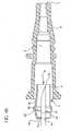
- Fig. 1is a perspective view of an over the needle catheter assembly for use In accord with an aspect of the invention
- Fig. 2Ais a cross-sectional view of one embodiment of the invention shown in an unactuated condition, where the needle has been partly withdrawn through the catheter but the sharp distal tip of the introducer needle has yet to be withdrawn into the needle shield;
- Fig. 2Bis a cross-sectional view of the embodiment of the needle shield in Fig. 2A in an actuated condition where the sharp distal tip of the introducer needle has been withdrawn proximally into the needle shield assembly;
- Fig. 3Ais a perspective view of the needle shield as depicted in Fig. 2A in partial cross section;
- Fig. 3Bis a perspective view of the needle shield as depicted in Fig. 2B in partial cross section;
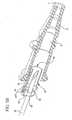
- Fig. 4Ais a cross-sectional view of another embodiment of the invention, with the canting plate and spring integral to the shield, shown in an unactuated condition, where the needle has been partly withdrawn through the catheter but the sharp distal tip of the introducer needle has yet to be withdrawn into the needle shield;
- Fig. 4Bis a cross-sectional view of the embodiment in Fig. 4A in an actuated condition where the sharp distal tip of the introducer needle has been withdrawn proximally into the needle shield assembly;
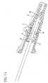
- Fig. 5Ais a cross-sectional perspective view of the needle shield of Fig. 4A ;
- Fig. 5Bis a cross-sectional perspective view of the needle shield assembly depicted in Fig. 48;
- Fig. 6Ais a cross-sectional view of another embodiment of the invention, with the canting plate, retention washer and spring integrally formed, shown in an unactuated condition, where the needle has been partly withdrawn through the catheter but the sharp distal tip of the introducer needle has yet to be withdrawn into the needle shield;
- Fig. 6Bis a cross-sectional view of the embodiment in Fig. 6A in an actuated condition where the sharp distal tip of the introducer needle has been withdrawn proximally into the needle shield assembly;
- Fig. 7Ais a cross-sectional perspective view of the needle shield of Fig. 6A ;
- Fig. 7Bis a perspective view of the needle shield assembly depicted in Fig. 6B in partial cross section.
- proximalrefers to a location on the catheter and needle shield assembly of this invention closest to the clinician using the device and farthest from the patient in connection with whom the device is used when the device is used in its normal operation.
- distalrefers to a location on the catheter and needle shield assembly of this invention farthest from the clinician using the device and closest to the patient in connection with whom the device is used when the device is used in its normal operation.
- a catheter assembly 100may include a catheter adapter 8 having a catheter 108 attached at its distal end. Wings 130 may be provided on the adapter 8. Before use and during insertion (as depicted in Fig. 1 ), a needle 30 is disposed within the catheter such that the tip or distal point 32 that extends out of the distal end of the catheter. The proximal end of the needle is attached to a needle hub 110. A finger grip 120 may be incorporated into the needle hub 110.
- Such a structure, in conjunction with the wings 130,permits the caregiver to employ various technique for catheter insertion, as discussed in U.S. Patent Application Serial No. 09/865,915, filed May 25, 2001 .
- a needle shield assembly 5is disposed about the needle, between the needle hub 110 and the catheter adapter 8, as shown in Fig. 1 .
- the needle shield assembly 5may be disposed completely within the catheter adapter and still practice aspects of the invention. It will be appreciated that embodiments of the invention may be implemented with either a needle shield assembly within the catheter adapter, or with a needle shield assembly disposed between the needle hub and the catheter adapter, or at other locations along the needle. Further, implementations of the invention may be employed with needles and sharps used in other devices, such as syringes and blood collection sets.
- implementations of the needle shield assembly 5are designed such that, after insertion of the over the needle catheter 108 into the patient, when the needle 30 is withdrawn, the tip 32 of the needle enters the needle shield assembly. At that point, the needle shield assembly locks onto the needle tip, preventing further displacement of the shield assembly along the needle. As such, the needle shield assembly cannot simply be slipped off the tip of the needle and removed. Additionally, when the needle shield assembly locks onto the needle, it prevents reemergence of the tip from the distal end of the needle shield assembly.
- the needle shield assemblyincludes a tilting member or canting plate 40 whose movement is constrained with respect to the needle shield assembly.
- the tilting memberis a rigid plate contained within the needle shield assembly.
- a hole 42 in the canting plateis defined by an edge 43. The needle passes through the hole 42 in the canting plate.
- the canting plateis retained in an aligned position with the needle by a retention system or canting plate retention means such that the needle passes through the canting plate without substantial interference.
- the canting plate retention meansmay include combinations of fixed structures and movable elements, springs and/or friction members that cooperate to control the position of the canting plate.
- the canting plate retention meansis triggered, causing the canting plate to come "off alignment" or be “actuated.”
- the canting plateis tilted such that it binds against the exterior of the needle, preventing relative movement of the needle to the canting plate. Since the canting plate is also constrained with respect to the needle shield assembly, the needle and its tip are also constrained with respect to the needle shield assembly - thereby locking the needle tip within the needle shield assembly.
- a feature 35may be provided on the needle to further prevent the needle shield assembly from slipping off the needle tip.
- a tethermay also be provided to prevent the needle shield assembly from slipping off the needle tip.
- the feature and the tethercan also serve to withdraw the needle shield assembly from the catheter adapter 8 as the needle hub 110 is moved proximally. Once locked in place, the shielded needle may be disposed of.
- FIGs. 2A-3Bone implementation of the invention is shown.
- Figs. 2A and 3Adepict the needle 30 partially withdrawn into the needle shield assembly 5, but before the needle shield assembly is actuated, or locked, onto the needle.
- Figs. 2B and 3Bdepict the needle shield assembly after actuation, locked onto the needle.
- the needle shield assembly 5is positioned within the catheter adapter (or simply "adapter") 8.
- the catheter 108has been omitted. It will be appreciated that the catheter is secured to the distal end of the catheter adapter and the needle extends coaxially through the catheter before use, as seen in Fig. 1 .
- the adapter 8includes an internal chamber forming a shield housing 6 in which the needle shield assembly 5 sits.
- the shield housingmay also be a structure distinct from the adapter.
- the needle shield assemblyhas a shield body 10 that includes a sidewall 9 and a distal end 11 and proximal end 12.
- the sidewallis cylindrical to fit snugly within the shield housing.
- the sidewallmay have other shapes to achieve a fit within the catheter adapter.
- the shield ends 11, 12include a distal opening 13 at the distal end and a proximal opening 14 at the proximal end.
- the needle 30has a distal needle point or tip 32 and an axis 99 and is disposed within the adapter 8, extending through the shield assembly 5 before use. Specifically, the needle passes through the shield openings 13, 14, and extends out of the distal end 7 of adapter 8, through an over-the-needle catheter 108 (not shown in Figs. 2A-3B for the sake of clarity).
- the needle diameteris sized to pass through the distal opening 13 and the proximal opening 14 of the shield body 10 without interference.
- a static feature 35is also provided on the needle 30 at a selected distance from the tip 32.
- the static feature 35is designed such that it is not capable of passage through the proximal opening 14 of shield body 10, such as disclosed in U.S. Patents 5,558,651 and 5,215,528 .
- the static featurecould be an increased diameter portion on the needle 30 (that is, an enlarged dimension, such as formed by a crimp, collar, enlarged diameter sleeve or ferrule), or a roughened surface that locks onto proximal end 12 of the needle shield assembly 5.
- Other structurescan be employed to restrict movement of the needle tip out of the proximal end of the shield (such as a tether, discussed below) and still practice aspects of the invention.
- the needle shield assembly 5contains a shielding mechanism including a canting plate 40 to restrict axial movement of the needle 30 within the shield body 10.
- the canting plateincludes a hole 42 defined by an edge 43 through which the needle passes.
- the proximal end 12 of the needle shield assemblyforms a retention washer 15.
- the retention washeris attached at one end (the top as seen in Fig. 2A ) to the sidewall 9.
- a spring 45is attached at the other end of the retention washer. The spring engages the canting plate; urging it to an off alignment position (that is, the actuated or locked position), as shown in Figs. 2B and 3B .
- the retention washer and springare integrally formed. It will be appreciated that these pieces could be separately formed and attached such as by welding or the like.
- the needle shield assembly 5also includes a retention arm 16.
- the retention armis a leaf spring, integrally formed with the sidewall 9 and including a lip 127 at its proximal end.
- the retention armis blased radially outward from the needle shield assembly, as seen in Fig. 2B .
- the shield housingforces the retention arm radially inward, as seen in Fig. 2A .
- the retention armhelps maintain the canting plate 40 in a needle aligned position (that is, the unactuated or unlocked position) while the needle shield assembly is in the shield housing.
- the needle shield assembly 5includes a ledge 27 formed in the sidewall 9, remote from the retention arm 16. As shown, the ledge is formed by deforming a portion of the sidewall such that it projects radially inwardly. It will be appreciated that the ledge could be formed in other manners (such as by adhering a distinct ledge structure to the inside of the side wall, or by crimping or otherwise creating a bulge in the sidewall). Importantly, the ledge forms a stop that prevents a portion of the canting plate from moving with respect to the needle shield assembly.
- the canting plate 40in the aligned or unlocked condition, the canting plate 40 is held in place by a retention system, specifically by the cooperation of the spring 45, the lip 127 of the retention arm 16 and the ledge 27.
- the springurges the top of the canting plate in the distal direction (to the right in Fig. 2A ).
- the canting plateis prevented from rotating or displacing by the lip of the retention arm, which engages the top of the canting plate, and the ledge, which engages the bottom of the canting plate.
- the canting platethus is maintained in the aligned condition and the needle may pass freely through the hole 42 in the canting plate without substantially engaging the edge 43.
- the needle 30After insertion into a patient's vein, the needle 30 is withdrawn through the catheter 108 and the catheter adapter 8.
- the feature 35 on the needleengages the proximal end 12 of the needle shield assembly 5.
- the feature 35 on the needledoes not fit through the hole 14 in the retention washer 15. Consequently, as the caregiver pulls the needle through the catheter adapter 8, the entire needle shield assembly 5 is pulled out of the shield housing 6.
- the retention arm 16succumbs to its natural bias, moving radially outward such that the lip 127 disengages the top of the canting plate 40. Once disengaged, the canting plate is free to rotate under the urging of the spring 45.
- edge 43 of the hole 42binds onto the exterior surface of the needle 30.
- the canting plateis held in this locked condition by the cooperation of the needle, the ledge 27 and the spring 45.
- the friction on the needleurging the canting plate distally
- the ledgepreventing movement of the bottom of the canting plate
- the feature 35may be sized so that it does not fit through the hole 42 in the canting plate when the canting plate is off alignment. This will provide further resistance to re-emergence of the needle tip.
- the canting plate 40may be a rigid disk with a hole 42 through the middle of it.
- the canting plate 40is substantially circular in shape but could be any of various other shapes including square, rectangular, triangular, oval, symmetrical, asymmetrical, etc.
- the hole 42 in the center of the canting plate 40is preferably substantially the same shape as the needle 30 that goes through it.
- other hole shapescould be employed, such as rectangular, triangular or oval shape or any of a variety of other shapes, and still practice aspects of the invention.
- the canting plateneed not be flat. It can be curved or stepped or otherwise shaped for any given application.
- the hole 42 in the canting plate 40is sized to achieve adequate binding force on the needle 30 in view of the geometry of the needle and the geometry of the canting plate.
- the holeshould be at least larger than the largest diameter of the feature 35 (when the feature is an enlarged portion of the needle) and, in certain implementations, may increase to be around 100% larger than the diameter of the static feature 35 on the needle 30.
- it is preferred that the hole 42is sized between just larger than the largest diameter of the static feature 35 on the needle 30 to a hole 42 about 10-30% larger than the largest diameter of the static feature 35 on the needle 30.
- the holebe sized, in view of the geometry of the needle shield assembly, such that it engages the needle when the canting plate is tilted between 0° and 45° from perpendicular to the axis 99.
- the canting anglemay be selected based on the geometry and materials of the canting plate, the needle shield assembly and the needle and the desired binding force.
- the hole 42 in the canting plate 40is aligned concentrically to the perimeter circular shape 46 of the body of the canting plate 40.
- the plate 40could also be designed to have an eccentric center hole 42 or a hole in any location on the canting plate 40 to achieve desirable binding forces.
- the hole 42may be positioned at the exterior or outer edge 46 of the canting plate such that it breaks the outer edge 46.
- Such a structurewill create a "slotted" style of canting plate 40 in accord with certain implementations of the invention. Such may be particularly desirable to permit side loading of the needle into the plate or for use with a guide-wire.
- the plate 40has a thickness suitable for use in providing edges 43 to bind down on the needle surface 31 when the plate 40 is canted or off alignment.
- This thickness 43may vary depending on other parameters, such as the materials used, the specific geometry of the other parts of the needle shield assembly and the binding force desired.
- the canting plate 40could be entirely housed within the shield body 10 or could be partially within and partially without the shield body 10.
- the operation of the structureis similar to that depicted in Figs. 2A-3B .
- the canting plate or member 40 and the retention washer 15are integrally formed from the same piece of material as the shield body 10 of the needle shield assembly 5.
- the canting plateis preferably made of stainless steel, or like material.
- the material that connects the canting plate 40 to the retention washer 15serves as the spring 45, urging the canting plate into an off alignment condition.
- the canting plate 40, the spring 45 and the retention washer 15are integral to each other, but separate from the proximal end 12 of the needle shield assembly 5.
- the retention washeris attached to the shield body 10 at the proximal end such as by welding, gluing or the like. As depicted, the retention washer is attached on the inner surface of the proximal end of the shield body, but it will be appreciated that the retention washer may be attached at the exterior surface as well.
- the operation of this implementationis otherwise similar to the prior implementations.
Landscapes
- Health & Medical Sciences (AREA)
- Life Sciences & Earth Sciences (AREA)
- Engineering & Computer Science (AREA)
- Anesthesiology (AREA)
- General Health & Medical Sciences (AREA)
- Biomedical Technology (AREA)
- Heart & Thoracic Surgery (AREA)
- Hematology (AREA)
- Veterinary Medicine (AREA)
- Animal Behavior & Ethology (AREA)
- Public Health (AREA)
- Biophysics (AREA)
- Pulmonology (AREA)
- Vascular Medicine (AREA)
- Environmental & Geological Engineering (AREA)
- Infusion, Injection, And Reservoir Apparatuses (AREA)
- Media Introduction/Drainage Providing Device (AREA)
Abstract
Description
- The subject invention relates to a needle shield assembly constructed to safely shield the sharp distal tip of a needle, and restrict distal movement of the needle tip via a tilting or "canting" plate after the tip is shielded.
- Intravenous (IV) catheters are used for infusing fluid, such as normal saline solution, various medicaments and total parenteral nutrition, into a patient or withdrawing blood from a patient. Peripheral IV catheters tend to be relatively short, and are on the order of about one and one-half inches in length. A common type of IV catheter is an over the needle peripheral IV catheter. As its name implies, an over the needle catheter is mounted over an introducer needle having a sharp distal tip. The catheter and the introducer needle are assembled so that the distal tip of the introducer needle extends beyond the distal tip of the catheter with the bevel of the needle facing up away from the patient's skin.
- The catheter and introducer needle assembly are inserted at a shallow angle through the patient's skin into a peripheral blood vessel (i.e., a smaller blood vessel that is not connected directly to the heart but is one of the branches of the central blood vessels that is directly connected to the heart). In order to verify proper placement of the assembly in the blood vessel, the clinician confirms that there is flashback of blood in the needle and in a flashback chamber located at the proximal end of the needle. Typically, the flashback chamber is formed as part of the needle hub. Once proper placement is confirmed, the clinician applies pressure to the blood vessel by pressing down on the patient's skin near the distal tip of the introducer needle and the catheter. This finger pressure occludes further blood flow through the introducer needle. The clinician withdraws the introducer needle, leaving the catheter in place, and attaches a fluid-handling device to the catheter hub. Once the introducer needle is withdrawn from the catheter, it is deemed a "blood contaminated sharp" and must be properly handled.
- In recent years, there has been great concern over the contamination of clinicians with a patient's blood and a recognition that "blood contaminated sharps" must be immediately disposed. This concern has arisen, in part, to reduce the risks associated with spreading diseases that can be transmitted by the exchange of body fluids from an infected person to another person. Thus, it is desirable to avoid contact with the body fluid of an infected person. Various needle shields have been developed. Generally, such needle shields work for their intended purpose but could be improved. For example, some needle shields are bulky, difficult to use or require special features or techniques to be operative.
- The pre-characterizing part of claim 1 refers to an over-the-needle catheter assembly as generally disclosed in
U.S. 5,910,132 . This catheter assembly comprises a needle having a needle hub and a catheter having a catheter hub. The catheter hub is releasably connected to a needle guard. The needle guard comprises a lock plate having an opening through which the needle freely passes when the catheter is in its ready position. The lock plate also includes an off-axis opening through which an actuator member passes. The actuator member is connected to a needle hub. In use, after the catheter is inserted into the patient's blood vessel, the needle hub is grasped to withdraw the needle from the patient and also to separate the needle hub from the needle guard. As the needle hub is retracted, the actuator member acts on the lock plate to cant or rock it about a fulcrum so that the lock plate grips and binds the needle shaft to prevent further axial motion of the needle. The actuator member is a tether or a wire that is almost as long as the needle is. EP 1 027 903 A1 describes a safety cover for locking the tip of a cannula therein. The safety cover comprises an elongate body which includes an axial channel having elements which displace and block linear passage of the cannula, once it has been retracted. The displacing element is a spring plate or canting plate which, when compressed, permits the cannula to pass through, but once the cannula has been retracted, expands to prevent the tip from being re-advanced. The clamping of the safety cover on the needle is caused when a tip of a spring arm is no longer supported by the needle so that the spring is deformed and the canting plate engages with the needle. There is no specific cooperation between a needle shield assembly and an adapter.WO 01/93940 A2 - It is an object of the invention to provide an over-the-needle catheter assembly having a novel type of canting plate retention means.
- The over-the-needle catheter assembly of the invention is defined by claim 1.
- In accord with the invention, an over the needle catheter assembly includes a catheter adapter and a needle. The needle has a diameter and a distal tip, slidingly disposed within the catheter adapter. A needle shield assembly is slidably mounted on the needle. The needle shield assembly has an open distal end and an open proximal end though which the needle passes. A rigid plate, referred to as a "canting plate," is disposed within the needle shield assembly and has an unactivated first position and an activated second position. In the second position, the canting plate restricts needle movement. Means for retaining the canting plate are provided. The canting plate retention means is in communication with the canting plate and responsive to proximal movement of the needle, whereby, when the needle tip is housed within the needle shield assembly, the canting plate retention means is actuated, causing distal movement of the needle to urge the canting plate from the unactivated first position to the activated second position.
- The canting plate retention means comprises a spring, a retention arm, and a retention washer. The spring may be selected from the group consisting of a coil spring, a wave washer, and a leaf spring or the like. The needle shield assembly may have a plurality of canting plates responsive to the canting plate retention means. The canting plate retention means may include a canting plate retention arm and a retention washer attached to the canting plate and having a built-in spring. The retention washer may be housed entirely within the shield. The canting plate retention means may include an elastomeric washer and an alignment arm. The elastomeric washer may have a truncated distal end. The catheter adapter and the shield may be held together by an interlock. A static feature may be provided on the needle, wherein said interlock is released prior to or substantially simultaneous with the static feature on the needle contacting the shield proximal end. The length between the needle tip and the static feature is such that when said static feature contacts the shield proximal end, the needle tip is housed within the shield. The canting plate may contain a hole for passage of the needle and be located distally of the proximal end of the shield. The canting plate may be returned to an unactivated position when the needle is no longer urged in a distal direction.
- The preferred embodiments are illustrated in the drawings in which like reference numerals refer to like elements and in which:
Fig. 1 is a perspective view of an over the needle catheter assembly for use In accord with an aspect of the invention;Fig. 2A is a cross-sectional view of one embodiment of the invention shown in an unactuated condition, where the needle has been partly withdrawn through the catheter but the sharp distal tip of the introducer needle has yet to be withdrawn into the needle shield;Fig. 2B is a cross-sectional view of the embodiment of the needle shield inFig. 2A in an actuated condition where the sharp distal tip of the introducer needle has been withdrawn proximally into the needle shield assembly;Fig. 3A is a perspective view of the needle shield as depicted inFig. 2A in partial cross section;Fig. 3B is a perspective view of the needle shield as depicted inFig. 2B in partial cross section;Fig. 4A is a cross-sectional view of another embodiment of the invention, with the canting plate and spring integral to the shield, shown in an unactuated condition, where the needle has been partly withdrawn through the catheter but the sharp distal tip of the introducer needle has yet to be withdrawn into the needle shield;Fig. 4B is a cross-sectional view of the embodiment inFig. 4A in an actuated condition where the sharp distal tip of the introducer needle has been withdrawn proximally into the needle shield assembly;Fig. 5A is a cross-sectional perspective view of the needle shield ofFig. 4A ;Fig. 5B is a cross-sectional perspective view of the needle shield assembly depicted in Fig. 48;Fig. 6A is a cross-sectional view of another embodiment of the invention, with the canting plate, retention washer and spring integrally formed, shown in an unactuated condition, where the needle has been partly withdrawn through the catheter but the sharp distal tip of the introducer needle has yet to be withdrawn into the needle shield;Fig. 6B is a cross-sectional view of the embodiment inFig. 6A in an actuated condition where the sharp distal tip of the introducer needle has been withdrawn proximally into the needle shield assembly;Fig. 7A is a cross-sectional perspective view of the needle shield ofFig. 6A ;Fig. 7B is a perspective view of the needle shield assembly depicted inFig. 6B in partial cross section.- As used herein, the term "proximal" refers to a location on the catheter and needle shield assembly of this invention closest to the clinician using the device and farthest from the patient in connection with whom the device is used when the device is used in its normal operation. Conversely, the term "distal" refers to a location on the catheter and needle shield assembly of this invention farthest from the clinician using the device and closest to the patient in connection with whom the device is used when the device is used in its normal operation.
- A
catheter assembly 100 may include acatheter adapter 8 having acatheter 108 attached at its distal end.Wings 130 may be provided on theadapter 8. Before use and during insertion (as depicted inFig. 1 ), aneedle 30 is disposed within the catheter such that the tip ordistal point 32 that extends out of the distal end of the catheter. The proximal end of the needle is attached to aneedle hub 110. Afinger grip 120 may be incorporated into theneedle hub 110. Such a structure, in conjunction with thewings 130, permits the caregiver to employ various technique for catheter insertion, as discussed inU.S. Patent Application Serial No. 09/865,915, filed May 25, 2001 - A
needle shield assembly 5 is disposed about the needle, between theneedle hub 110 and thecatheter adapter 8, as shown inFig. 1 . Alternatively, as shown in,inter alia,Figs. 2A and2B , theneedle shield assembly 5 may be disposed completely within the catheter adapter and still practice aspects of the invention. It will be appreciated that embodiments of the invention may be implemented with either a needle shield assembly within the catheter adapter, or with a needle shield assembly disposed between the needle hub and the catheter adapter, or at other locations along the needle. Further, implementations of the invention may be employed with needles and sharps used in other devices, such as syringes and blood collection sets. - As discussed more fully below, implementations of the
needle shield assembly 5 are designed such that, after insertion of the over theneedle catheter 108 into the patient, when theneedle 30 is withdrawn, thetip 32 of the needle enters the needle shield assembly. At that point, the needle shield assembly locks onto the needle tip, preventing further displacement of the shield assembly along the needle. As such, the needle shield assembly cannot simply be slipped off the tip of the needle and removed. Additionally, when the needle shield assembly locks onto the needle, it prevents reemergence of the tip from the distal end of the needle shield assembly. - To achieve this locking between the
needle shield assembly 5 and theneedle 30, the needle shield assembly includes a tilting member or cantingplate 40 whose movement is constrained with respect to the needle shield assembly. Preferably, the tilting member is a rigid plate contained within the needle shield assembly. Ahole 42 in the canting plate is defined by anedge 43. The needle passes through thehole 42 in the canting plate. In the unlocked condition (seen, e.g., inFig. 2A ), the canting plate is retained in an aligned position with the needle by a retention system or canting plate retention means such that the needle passes through the canting plate without substantial interference. As discussed more fully below, the canting plate retention means may include combinations of fixed structures and movable elements, springs and/or friction members that cooperate to control the position of the canting plate. As thetip 32 of the needle is withdrawn into the needle shield assembly, the canting plate retention means is triggered, causing the canting plate to come "off alignment" or be "actuated." The canting plate is tilted such that it binds against the exterior of the needle, preventing relative movement of the needle to the canting plate. Since the canting plate is also constrained with respect to the needle shield assembly, the needle and its tip are also constrained with respect to the needle shield assembly - thereby locking the needle tip within the needle shield assembly. Afeature 35 may be provided on the needle to further prevent the needle shield assembly from slipping off the needle tip. A tether may also be provided to prevent the needle shield assembly from slipping off the needle tip. As discussed below, the feature and the tether can also serve to withdraw the needle shield assembly from thecatheter adapter 8 as theneedle hub 110 is moved proximally. Once locked in place, the shielded needle may be disposed of. - Referring now to
Figs. 2A-3B , one implementation of the invention is shown.Figs. 2A and3A depict theneedle 30 partially withdrawn into theneedle shield assembly 5, but before the needle shield assembly is actuated, or locked, onto the needle.Figs. 2B and3B depict the needle shield assembly after actuation, locked onto the needle. In the unlocked or unactuated condition (Figs. 2A and3A ), theneedle shield assembly 5 is positioned within the catheter adapter (or simply "adapter")8. For the sake of clarity, thecatheter 108 has been omitted. It will be appreciated that the catheter is secured to the distal end of the catheter adapter and the needle extends coaxially through the catheter before use, as seen inFig. 1 . Theadapter 8 includes an internal chamber forming ashield housing 6 in which theneedle shield assembly 5 sits. The shield housing may also be a structure distinct from the adapter. The needle shield assembly has ashield body 10 that includes asidewall 9 and adistal end 11 andproximal end 12. Typically, the sidewall is cylindrical to fit snugly within the shield housing. The sidewall may have other shapes to achieve a fit within the catheter adapter. The shield ends11, 12 include adistal opening 13 at the distal end and aproximal opening 14 at the proximal end. - The
needle 30 has a distal needle point ortip 32 and anaxis 99 and is disposed within theadapter 8, extending through theshield assembly 5 before use. Specifically, the needle passes through theshield openings distal end 7 ofadapter 8, through an over-the-needle catheter108 (not shown inFigs. 2A-3B for the sake of clarity). The needle diameter is sized to pass through thedistal opening 13 and theproximal opening 14 of theshield body 10 without interference. - In accord with the invention, a
static feature 35 is also provided on theneedle 30 at a selected distance from thetip 32. Thestatic feature 35 is designed such that it is not capable of passage through theproximal opening 14 ofshield body 10, such as disclosed inU.S. Patents 5,558,651 and5,215,528 . The static feature could be an increased diameter portion on the needle30 (that is, an enlarged dimension, such as formed by a crimp, collar, enlarged diameter sleeve or ferrule), or a roughened surface that locks ontoproximal end 12 of theneedle shield assembly 5. Other structures can be employed to restrict movement of the needle tip out of the proximal end of the shield (such as a tether, discussed below) and still practice aspects of the invention. - The
needle shield assembly 5 contains a shielding mechanism including acanting plate 40 to restrict axial movement of theneedle 30 within theshield body 10. The canting plate includes ahole 42 defined by anedge 43 through which the needle passes. Theproximal end 12 of the needle shield assembly forms aretention washer 15. The retention washer is attached at one end (the top as seen inFig. 2A ) to thesidewall 9. Aspring 45 is attached at the other end of the retention washer. The spring engages the canting plate; urging it to an off alignment position (that is, the actuated or locked position), as shown inFigs. 2B and3B . As shown, the retention washer and spring are integrally formed. It will be appreciated that these pieces could be separately formed and attached such as by welding or the like. - The
needle shield assembly 5 also includes aretention arm 16. Preferably, the retention arm is a leaf spring, integrally formed with thesidewall 9 and including alip 127 at its proximal end. Of course, other structures could be employed and practice aspects of the invention. The retention arm is blased radially outward from the needle shield assembly, as seen inFig. 2B . When the needle shield assembly is disposed in theshield housing 6, the shield housing forces the retention arm radially inward, as seen inFig. 2A . As discussed below, the retention arm helps maintain thecanting plate 40 in a needle aligned position (that is, the unactuated or unlocked position) while the needle shield assembly is in the shield housing. - The
needle shield assembly 5 includes aledge 27 formed in thesidewall 9, remote from theretention arm 16. As shown, the ledge is formed by deforming a portion of the sidewall such that it projects radially inwardly. It will be appreciated that the ledge could be formed in other manners (such as by adhering a distinct ledge structure to the inside of the side wall, or by crimping or otherwise creating a bulge in the sidewall). Importantly, the ledge forms a stop that prevents a portion of the canting plate from moving with respect to the needle shield assembly. - The operation of the
needle shield assembly 5 ofFigs. 2A-3B will now be discussed. Referring toFig. 2A , in the aligned or unlocked condition, thecanting plate 40 is held in place by a retention system, specifically by the cooperation of thespring 45, thelip 127 of theretention arm 16 and theledge 27. The spring urges the top of the canting plate in the distal direction (to the right inFig. 2A ). When the needle shield assembly is positioned in theshield housing 6 of thecatheter adapter 8, the canting plate is prevented from rotating or displacing by the lip of the retention arm, which engages the top of the canting plate, and the ledge, which engages the bottom of the canting plate. The canting plate thus is maintained in the aligned condition and the needle may pass freely through thehole 42 in the canting plate without substantially engaging theedge 43. - After insertion into a patient's vein, the
needle 30 is withdrawn through thecatheter 108 and thecatheter adapter 8. Thefeature 35 on the needle engages theproximal end 12 of theneedle shield assembly 5. As shown inFigs. 2B and3B , thefeature 35 on the needle does not fit through thehole 14 in theretention washer 15. Consequently, as the caregiver pulls the needle through thecatheter adapter 8, the entireneedle shield assembly 5 is pulled out of theshield housing 6. Upon removal of the needle shield assembly, theretention arm 16 succumbs to its natural bias, moving radially outward such that thelip 127 disengages the top of thecanting plate 40. Once disengaged, the canting plate is free to rotate under the urging of thespring 45. As the canting plate rotates, edge43 of thehole 42 binds onto the exterior surface of theneedle 30. The canting plate is held in this locked condition by the cooperation of the needle, theledge 27 and thespring 45. Should the needle be pushed distally in an effort to cause the needle tip to reemerge from the needle shield assembly, the friction on the needle (urging the canting plate distally) and the ledge (preventing movement of the bottom of the canting plate) will cause the canting plate to tilt more severely with respect to the needle, increasing the binding force between the canting plate and the needle, thereby resisting such movement. It will also be appreciated that thefeature 35 may be sized so that it does not fit through thehole 42 in the canting plate when the canting plate is off alignment. This will provide further resistance to re-emergence of the needle tip. - As readily seen in
Fig. 3A , thecanting plate 40 may be a rigid disk with ahole 42 through the middle of it. As shown, thecanting plate 40 is substantially circular in shape but could be any of various other shapes including square, rectangular, triangular, oval, symmetrical, asymmetrical, etc. Thehole 42 in the center of thecanting plate 40 is preferably substantially the same shape as theneedle 30 that goes through it. However, other hole shapes could be employed, such as rectangular, triangular or oval shape or any of a variety of other shapes, and still practice aspects of the invention. Further, the canting plate need not be flat. It can be curved or stepped or otherwise shaped for any given application. - The
hole 42 in thecanting plate 40 is sized to achieve adequate binding force on theneedle 30 in view of the geometry of the needle and the geometry of the canting plate. Specifically, the hole should be at least larger than the largest diameter of the feature35 (when the feature is an enlarged portion of the needle) and, in certain implementations, may increase to be around 100% larger than the diameter of thestatic feature 35 on theneedle 30. In certain other applications, it is preferred that thehole 42 is sized between just larger than the largest diameter of thestatic feature 35 on theneedle 30 to ahole 42 about 10-30% larger than the largest diameter of thestatic feature 35 on theneedle 30. In yet other implementations, it is desirable that the hole be sized, in view of the geometry of the needle shield assembly, such that it engages the needle when the canting plate is tilted between 0° and 45° from perpendicular to theaxis 99. It will be appreciated that the canting angle may be selected based on the geometry and materials of the canting plate, the needle shield assembly and the needle and the desired binding force. - When the
needle shield assembly 5 is in the unlocked condition (and the canting plate is therefore aligned with the needle), thehole 42 in thecanting plate 40 is aligned concentrically to the perimetercircular shape 46 of the body of thecanting plate 40. Theplate 40 could also be designed to have aneccentric center hole 42 or a hole in any location on thecanting plate 40 to achieve desirable binding forces. Further, thehole 42 may be positioned at the exterior orouter edge 46 of the canting plate such that it breaks theouter edge 46. Such a structure will create a "slotted" style of cantingplate 40 in accord with certain implementations of the invention. Such may be particularly desirable to permit side loading of the needle into the plate or for use with a guide-wire. - The
plate 40 has a thickness suitable for use in providingedges 43 to bind down on the needle surface31 when theplate 40 is canted or off alignment. Thisthickness 43, however, may vary depending on other parameters, such as the materials used, the specific geometry of the other parts of the needle shield assembly and the binding force desired. - The
canting plate 40 could be entirely housed within theshield body 10 or could be partially within and partially without theshield body 10. Asingle canting plate 40 or a plurality of canting plates, could be used. In the case of a plurality of canting plates, they could be disposed immediately adjacent to each other, separated by a gap between them, or a combination of both. - Turning to the implementation of the invention shown in
Figs. 4A-5B , the operation of the structure is similar to that depicted inFigs. 2A-3B . In this implementation, however, the canting plate ormember 40 and theretention washer 15 are integrally formed from the same piece of material as theshield body 10 of theneedle shield assembly 5. The canting plate is preferably made of stainless steel, or like material. The material that connects thecanting plate 40 to theretention washer 15 serves as thespring 45, urging the canting plate into an off alignment condition. Again, during and after actuation, proximal motion of theneedle 30 with respect to theneedle shield assembly 5 is halted by the interference between thestatic feature 35 on theneedle 30 and theretention washer 15. After actuation, distal motion of theneedle 30 with respect to theneedle shield assembly 5 is halted by the engagement of thecanting plate 40 to the needle, as discussed above. It will be appreciated that noledge 27 is required because thespring 45, and its connection with theretention washer 15, restrain the bottom edge of the canting plate from moving with respect to the needle shield assembly. Further, a tether could be employed instead offeature 35 to limit the relative movement of the needle hub and the catheter adapter. - Turning to the implementation of the invention shown in
Figs. 6A-7B , thecanting plate 40, thespring 45 and theretention washer 15 are integral to each other, but separate from theproximal end 12 of theneedle shield assembly 5. The retention washer is attached to theshield body 10 at the proximal end such as by welding, gluing or the like. As depicted, the retention washer is attached on the inner surface of the proximal end of the shield body, but it will be appreciated that the retention washer may be attached at the exterior surface as well. The operation of this implementation is otherwise similar to the prior implementations.
Claims (7)
- An over-the-needle catheter assembly comprising:an adapter (8) having a shield housing (6),a needle (30) having a diameter and a distal tip (32), slidingly disposed within the adapter;a needle shield assembly (5) movable with respect to the adapter (8) and slidably mounted on the needle, wherein the needle shield assembly has an open distal end (13) and an open proximal end (12) through which the needle passes;a canting plate (40) disposed within the needle shield assembly and having a hole (42) for passage of the needle, said canting plate having an unactivated first position and an activated second position restricting needle movement;means (15, 16, 19) for retaining the canting plate, in communication with the canting plate (40) and responsive to proximal movement of the needle (30), whereby, when the needle tip (32) is housed within the needle shield assembly (5), the canting plate retention means is actuated, allowing movement of the canting plate from the unactivated first position to the activated second position, said means comprising a retention washer (15) having a proximal opening (14) for the needle,characterized in that
the needle (30) comprises a static feature (35) which cannot pass the opening (14) of the retention washer, whereby, when the needle is pulled proximally, said needle also pulls the needle shield assembly (5) so that the needle shield assembly leaves the shield housing (6) of the adapter (8), and
the canting plate retention means (15, 16) comprises a spring (45) urging the canting plate (40) into the activated second position, and a retention arm (16) which, when the needle shield assembly (5) is pulled out of the adapter (8), moves due to its natural bias from an engaged position, wherein the retention arm retains the canting plate in the unactivated first position, to a disengaged position, wherein the retention arm releases the canting plate to the activated second position. - The catheter assembly of claim 1, wherein said spring (45) is selected from the group consisting of a coil spring, an elastomeric member (28), a wave washer, and a leaf spring.
- The catheter assembly of claim 1, wherein the canting plate retention arm (16) and the retention washer (15) are attached to the canting plate, wherein said spring (45) is a built-in spring.
- The catheter assembly of claim 4, wherein the retention washer (15) is housed within the needle shield (5).
- The catheter assembly of claim 1, wherein the needle shield assembly (5) forms an integral part comprising said spring (45), said retention washer (15) and said retention arm (16).
- The catheter assembly of claim 1, wherein the canting plate (40) is located distally of the proximal end (14) of the shield.
- The needle shield assembly of claim 1, wherein said canting plate (40) is returned to an unactivated position when said needle (30) is, no longer urged in distal direction.
Priority Applications (10)
| Application Number | Priority Date | Filing Date | Title |
|---|---|---|---|
| EP07117417.1AEP1886710B1 (en) | 2002-06-20 | 2003-06-20 | Catheter and introducer needle assembly with needle shield |
| EP10158840AEP2204211B1 (en) | 2002-06-20 | 2003-06-20 | Catheter and introducer needle assembly with needle shield |
| EP10158829AEP2204210B1 (en) | 2002-06-20 | 2003-06-20 | Catheter and introducer needle assembly with needle shield |
| EP10179388.3AEP2298404B1 (en) | 2002-06-20 | 2003-06-20 | Catheter and introducer needle assembly with needle shield |
| EP10179409.7AEP2298405B1 (en) | 2002-06-20 | 2003-06-20 | Catheter and introducer needle assembly with needle shield |
| EP10158847AEP2204212B1 (en) | 2002-06-20 | 2003-06-20 | Catheter and introducer needle assembly with needle shield |
| EP10158815AEP2204209B1 (en) | 2002-06-20 | 2003-06-20 | Catheter and introducer needle assembly with needle shield |
| EP19197029.2AEP3639881A1 (en) | 2002-06-20 | 2003-06-20 | Catheter and introducer needle assembly with needle shield |
| EP16191525.1AEP3184142B1 (en) | 2002-06-20 | 2003-06-20 | Catheter and introducer needle assembly with needle shield |
| EP16183358.7AEP3159032B1 (en) | 2002-06-20 | 2003-06-20 | Catheter and introducer needle assembly with needle shield |
Applications Claiming Priority (5)
| Application Number | Priority Date | Filing Date | Title |
|---|---|---|---|
| US39049902P | 2002-06-20 | 2002-06-20 | |
| US390499P | 2002-06-20 | ||
| US10/320,960US6652490B2 (en) | 1998-04-09 | 2002-12-17 | Catheter and introducer needle assembly with compact needle shield |
| US320960 | 2002-12-17 | ||
| PCT/US2003/019670WO2004000408A1 (en) | 2002-06-20 | 2003-06-20 | Catheter and introducer needle assembly with needle shield |
Related Child Applications (7)
| Application Number | Title | Priority Date | Filing Date |
|---|---|---|---|
| EP19197029.2ADivisionEP3639881A1 (en) | 2002-06-20 | 2003-06-20 | Catheter and introducer needle assembly with needle shield |
| EP10179409.7ADivisionEP2298405B1 (en) | 2002-06-20 | 2003-06-20 | Catheter and introducer needle assembly with needle shield |
| EP07117417.1ADivisionEP1886710B1 (en) | 2002-06-20 | 2003-06-20 | Catheter and introducer needle assembly with needle shield |
| EP10179388.3ADivisionEP2298404B1 (en) | 2002-06-20 | 2003-06-20 | Catheter and introducer needle assembly with needle shield |
| EP16183358.7ADivisionEP3159032B1 (en) | 2002-06-20 | 2003-06-20 | Catheter and introducer needle assembly with needle shield |
| EP16191525.1ADivisionEP3184142B1 (en) | 2002-06-20 | 2003-06-20 | Catheter and introducer needle assembly with needle shield |
| EP07117417.1Division-Into | 2007-09-27 |
Publications (2)
| Publication Number | Publication Date |
|---|---|
| EP1513579A1 EP1513579A1 (en) | 2005-03-16 |
| EP1513579B1true EP1513579B1 (en) | 2010-04-07 |
Family
ID=41573530
Family Applications (9)
| Application Number | Title | Priority Date | Filing Date |
|---|---|---|---|
| EP07117417.1AExpired - LifetimeEP1886710B1 (en) | 2002-06-20 | 2003-06-20 | Catheter and introducer needle assembly with needle shield |
| EP16183358.7AExpired - LifetimeEP3159032B1 (en) | 2002-06-20 | 2003-06-20 | Catheter and introducer needle assembly with needle shield |
| EP10158829AExpired - LifetimeEP2204210B1 (en) | 2002-06-20 | 2003-06-20 | Catheter and introducer needle assembly with needle shield |
| EP19197029.2AWithdrawnEP3639881A1 (en) | 2002-06-20 | 2003-06-20 | Catheter and introducer needle assembly with needle shield |
| EP10158847AExpired - LifetimeEP2204212B1 (en) | 2002-06-20 | 2003-06-20 | Catheter and introducer needle assembly with needle shield |
| EP03761229AExpired - LifetimeEP1513579B1 (en) | 2002-06-20 | 2003-06-20 | Catheter and introducer needle assembly with needle shield |
| EP10158815AExpired - LifetimeEP2204209B1 (en) | 2002-06-20 | 2003-06-20 | Catheter and introducer needle assembly with needle shield |
| EP16191525.1AExpired - LifetimeEP3184142B1 (en) | 2002-06-20 | 2003-06-20 | Catheter and introducer needle assembly with needle shield |
| EP10158840AExpired - LifetimeEP2204211B1 (en) | 2002-06-20 | 2003-06-20 | Catheter and introducer needle assembly with needle shield |
Family Applications Before (5)
| Application Number | Title | Priority Date | Filing Date |
|---|---|---|---|
| EP07117417.1AExpired - LifetimeEP1886710B1 (en) | 2002-06-20 | 2003-06-20 | Catheter and introducer needle assembly with needle shield |
| EP16183358.7AExpired - LifetimeEP3159032B1 (en) | 2002-06-20 | 2003-06-20 | Catheter and introducer needle assembly with needle shield |
| EP10158829AExpired - LifetimeEP2204210B1 (en) | 2002-06-20 | 2003-06-20 | Catheter and introducer needle assembly with needle shield |
| EP19197029.2AWithdrawnEP3639881A1 (en) | 2002-06-20 | 2003-06-20 | Catheter and introducer needle assembly with needle shield |
| EP10158847AExpired - LifetimeEP2204212B1 (en) | 2002-06-20 | 2003-06-20 | Catheter and introducer needle assembly with needle shield |
Family Applications After (3)
| Application Number | Title | Priority Date | Filing Date |
|---|---|---|---|
| EP10158815AExpired - LifetimeEP2204209B1 (en) | 2002-06-20 | 2003-06-20 | Catheter and introducer needle assembly with needle shield |
| EP16191525.1AExpired - LifetimeEP3184142B1 (en) | 2002-06-20 | 2003-06-20 | Catheter and introducer needle assembly with needle shield |
| EP10158840AExpired - LifetimeEP2204211B1 (en) | 2002-06-20 | 2003-06-20 | Catheter and introducer needle assembly with needle shield |
Country Status (10)
| Country | Link |
|---|---|
| US (1) | US7935080B2 (en) |
| EP (9) | EP1886710B1 (en) |
| JP (3) | JP4457004B2 (en) |
| CN (2) | CN101628144B (en) |
| AT (5) | ATE463273T1 (en) |
| AU (1) | AU2003243717A1 (en) |
| BR (1) | BR0311937B1 (en) |
| DE (1) | DE60332019D1 (en) |
| ES (12) | ES2697329T3 (en) |
| WO (1) | WO2004000408A1 (en) |
Families Citing this family (145)
| Publication number | Priority date | Publication date | Assignee | Title |
|---|---|---|---|---|
| US7413562B2 (en)* | 2001-03-15 | 2008-08-19 | Specialized Health Products, Inc. | Safety shield for medical needles |
| US8066678B2 (en)* | 2001-12-17 | 2011-11-29 | Bard Access Systems, Inc. | Safety needle with collapsible sheath |
| EP1762262A3 (en)* | 2004-02-13 | 2007-03-21 | Smiths Medical ASD, Inc. | Needle tip protector |
| US7513888B2 (en)* | 2004-02-17 | 2009-04-07 | Smiths Medical Asd, Inc. | Needle guards |
| US7776016B1 (en) | 2004-02-26 | 2010-08-17 | C. R. Bard, Inc. | Huber needle safety enclosure |
| US7651476B2 (en)* | 2004-09-28 | 2010-01-26 | B. Braun Medical Inc. | Protective clips |
| US7828773B2 (en) | 2005-07-11 | 2010-11-09 | Covidien Ag | Safety reset key and needle assembly |
| US7850650B2 (en) | 2005-07-11 | 2010-12-14 | Covidien Ag | Needle safety shield with reset |
| US7905857B2 (en) | 2005-07-11 | 2011-03-15 | Covidien Ag | Needle assembly including obturator with safety reset |
| CA2599945C (en)* | 2005-03-07 | 2011-07-12 | Erskine Medical Llc | Catheter introducer with needle shield |
| US20060276747A1 (en) | 2005-06-06 | 2006-12-07 | Sherwood Services Ag | Needle assembly with removable depth stop |
| EP1907042B1 (en) | 2005-07-06 | 2009-03-11 | Vascular Pathways Inc. | Intravenous catheter insertion device and method of use |
| US7731692B2 (en) | 2005-07-11 | 2010-06-08 | Covidien Ag | Device for shielding a sharp tip of a cannula and method of using the same |
| US7753877B2 (en) | 2005-08-08 | 2010-07-13 | Smiths Medical Asd, Inc. | Needle guard strut wall clip |
| US7632243B2 (en) | 2005-08-08 | 2009-12-15 | Smiths Medical Asd, Inc. | Duckbill catheter release mechanism |
| US7597681B2 (en)* | 2005-08-08 | 2009-10-06 | Smiths Medical Asd, Inc. | Needle guard mechanism with shroud |
| US8251950B2 (en) | 2005-08-08 | 2012-08-28 | Smiths Medical Asd, Inc. | Needle guard clip with heel |
| US8162881B2 (en)* | 2005-08-08 | 2012-04-24 | Smiths Medical Asd, Inc. | Needle guard mechanism with angled strut wall |
| US8403886B2 (en) | 2005-08-08 | 2013-03-26 | Smiths Medical Asd, Inc. | Needle guard clip with lip |
| US7654735B2 (en) | 2005-11-03 | 2010-02-02 | Covidien Ag | Electronic thermometer |
| US7658725B2 (en) | 2006-02-16 | 2010-02-09 | Smiths Medical Asd, Inc. | Enclosed needle device with duckbill release mechanism |
| US20080097330A1 (en)* | 2006-07-18 | 2008-04-24 | Smiths Medical Asd, Inc. | Catheter insertion device with fluid leakage control |
| CN101112638B (en)* | 2006-07-27 | 2011-06-08 | 贝克顿·迪金森公司 | Catheter and introducer needle assembly with safety device |
| CN101112639B (en)* | 2006-07-27 | 2012-07-18 | 贝克顿·迪金森公司 | Vessel having a safeguard device and introducing needle component |
| US8382718B2 (en)* | 2006-07-31 | 2013-02-26 | B. Braun Melsungen Ag | Needle assembly and components thereof |
| JP4994775B2 (en) | 2006-10-12 | 2012-08-08 | 日本コヴィディエン株式会社 | Needle point protector |
| US7871397B2 (en) | 2006-12-26 | 2011-01-18 | Stat Medical Devices, Inc. | Pen needle tip |
| EP3108812B1 (en)* | 2007-03-07 | 2020-04-29 | Becton, Dickinson and Company | Safety blood collection assembly with indicator |
| US8597253B2 (en) | 2007-04-20 | 2013-12-03 | Bard Access Systems | Huber needle with safety sheath |
| EP2150304B1 (en) | 2007-05-07 | 2010-12-01 | Vascular Pathways Inc. | Intravenous catheter insertion and blood sample devices and method of use |
| US8357104B2 (en) | 2007-11-01 | 2013-01-22 | Coviden Lp | Active stylet safety shield |
| WO2009067646A1 (en) | 2007-11-21 | 2009-05-28 | Becton, Dickinson And Company | Needle safety device |
| US8858503B2 (en)* | 2007-12-21 | 2014-10-14 | Becton, Dickinson And Company | Tip shield with gripping surfaces and guard features |
| EP2077133A1 (en) | 2008-01-03 | 2009-07-08 | Eastern Medikit Ltd. | Safety I.V. catheter with tip locking insert |
| USD659825S1 (en)* | 2009-11-13 | 2012-05-15 | Protectus Medical Devices, Inc. | Living hinge lock collar |
| EP2161049A1 (en)* | 2008-09-05 | 2010-03-10 | Eastern Medikit Ltd. | Safety IV catheter with tip protective housing |
| EP2168627A1 (en)* | 2008-09-11 | 2010-03-31 | Eastern Medikit Ltd. | Safety I.V. catheter with cylindrical tip protector |
| US8231582B2 (en) | 2008-12-11 | 2012-07-31 | Bard Access Systems, Inc. | Device for removing a Huber needle from a patient |
| US8439877B2 (en)* | 2009-03-02 | 2013-05-14 | Becton, Dickinson And Company | Bi-directionally engageable cannula crimp feature |
| US8496623B2 (en)* | 2009-03-02 | 2013-07-30 | Becton, Dickinson And Company | Bi-directional cannula feature capture mechanism |
| US9399120B2 (en) | 2009-03-02 | 2016-07-26 | Becton, Dickinson And Company | Bi-directional cannula feature capture mechanism |
| US8936575B2 (en)* | 2009-03-19 | 2015-01-20 | Becton, Dickinson And Company | Cannula-tip shielding mechanism |
| US20110023281A1 (en)* | 2009-04-30 | 2011-02-03 | Stat Medical Devices, Inc. | Pen injection device cap with integral pen needle quick release and/or removal system |
| DE102009020061A1 (en) | 2009-05-06 | 2010-11-11 | B. Braun Melsungen Ag | Needle protection device for a medical hollow needle |
| US9700681B2 (en)* | 2009-05-15 | 2017-07-11 | Stat Medical Devices, Inc. | Pen needle with quick release and/or removal system |
| US20100305519A1 (en)* | 2009-06-02 | 2010-12-02 | Becton, Dickinson And Company | Cannula having an overlapping cannula feature and notch feature |
| US8474300B2 (en)* | 2009-07-20 | 2013-07-02 | Becton, Dickinson And Company | Methods to provide a feature on a needle |
| SE534021C2 (en) | 2009-08-13 | 2011-04-05 | Vigmed Ab | Protective device for a catheter needle tip |
| US20110060292A1 (en)* | 2009-08-14 | 2011-03-10 | Stat Medical Devices, Inc. | Pen needle storage device with integral removal and/or installation system |
| SE535169C2 (en)* | 2010-04-13 | 2012-05-08 | Vigmed Ab | Polymer protective device for a catheter needle tip |
| US9950139B2 (en) | 2010-05-14 | 2018-04-24 | C. R. Bard, Inc. | Catheter placement device including guidewire and catheter control elements |
| US11925779B2 (en) | 2010-05-14 | 2024-03-12 | C. R. Bard, Inc. | Catheter insertion device including top-mounted advancement components |
| US9872971B2 (en) | 2010-05-14 | 2018-01-23 | C. R. Bard, Inc. | Guidewire extension system for a catheter placement device |
| US10384039B2 (en) | 2010-05-14 | 2019-08-20 | C. R. Bard, Inc. | Catheter insertion device including top-mounted advancement components |
| US8932258B2 (en) | 2010-05-14 | 2015-01-13 | C. R. Bard, Inc. | Catheter placement device and method |
| US8257322B2 (en) | 2010-06-02 | 2012-09-04 | Smiths Medical Asd, Inc. | Tip protector for a safety catheter |
| CN102284110A (en)* | 2010-06-18 | 2011-12-21 | 苏州康益明华生物医药科技有限公司 | Sheath-type safety needle guard |
| CN102284109A (en)* | 2010-06-18 | 2011-12-21 | 苏州康益明华生物医药科技有限公司 | Receiving type safe needle protector with sheath |
| FR2961701B1 (en)* | 2010-06-28 | 2014-06-20 | Braun Medical Sas | NEEDLE FOR INJECTING OR EXTRACTING FLUIDS WITH A SAFETY DEVICE FOR PROTECTING AGAINST INJURIES ON THE NEEDLE'S NEEDLE |
| US10525234B2 (en) | 2010-09-10 | 2020-01-07 | C. R. Bard, Inc. | Antimicrobial/haemostatic interface pad for placement between percutaneously placed medical device and patient skin |
| EP2613824A1 (en) | 2010-09-10 | 2013-07-17 | C.R. Bard Inc. | Systems for isolation of a needle-based infusion set |
| US20140066894A1 (en) | 2010-09-10 | 2014-03-06 | C. R. Bard, Inc. | Self-Sealing Pad for a Needle-Based Infusion Set |
| ES2721902T5 (en) | 2010-09-23 | 2023-06-28 | Greiner Bio One Gmbh | Needle tip protection device |
| US9428254B1 (en) | 2010-09-24 | 2016-08-30 | Katalyst Surgical, Llc | Microsurgical handle and instrument |
| US10463803B2 (en) | 2010-11-12 | 2019-11-05 | Stat Medical Devices, Inc. | Pen needle with quick release and/or removal system |
| ES2725777T3 (en) | 2010-12-02 | 2019-09-27 | Erskine Medical Llc | Release mechanism for use with needle protection devices |
| MY161281A (en) | 2010-12-02 | 2017-04-14 | Erskine Medical Llc | Needle shield assembly with hub engagement member for needle device |
| US8690833B2 (en) | 2011-01-31 | 2014-04-08 | Vascular Pathways, Inc. | Intravenous catheter and insertion device with reduced blood spatter |
| US8961470B2 (en) | 2011-02-17 | 2015-02-24 | Steven Schraga | Pen needle with safety shield system |
| ES2835652T3 (en) | 2011-02-25 | 2021-06-22 | Bard Inc C R | Medical component insertion device including a retractable needle |
| US8764711B2 (en) | 2011-02-28 | 2014-07-01 | Injectimed, Inc. | Needle guard |
| US9238104B2 (en) | 2011-02-28 | 2016-01-19 | Injectimed, Inc. | Needle guard |
| WO2012139034A1 (en) | 2011-04-07 | 2012-10-11 | Erskine Medical Llc | Needle shielding device |
| ES2662356T3 (en) | 2011-04-27 | 2018-04-06 | Kpr U.S., Llc | Safety IV catheter assemblies |
| USD903101S1 (en) | 2011-05-13 | 2020-11-24 | C. R. Bard, Inc. | Catheter |
| WO2013048975A1 (en) | 2011-09-26 | 2013-04-04 | Covidien Lp | Safety catheter |
| EP2760521B1 (en) | 2011-09-26 | 2016-01-06 | Covidien LP | Safety iv catheter and needle assembly |
| US8834422B2 (en) | 2011-10-14 | 2014-09-16 | Covidien Lp | Vascular access assembly and safety device |
| ES2666386T3 (en) | 2011-12-07 | 2018-05-04 | Becton, Dickinson And Company | Needle protection sets and infusion devices for use with them |
| US9078978B2 (en) | 2011-12-28 | 2015-07-14 | Stat Medical Devices, Inc. | Needle assembly with safety system for a syringe or fluid sampling device and method of making and using the same |
| US9468423B2 (en)* | 2012-01-10 | 2016-10-18 | Becton, Dickinson And Company | Safety shield for fluid specimen container |
| US9138346B2 (en) | 2012-01-26 | 2015-09-22 | Katalyst Surgical, Llc | Surgical instrument sleeve |
| SE537334C2 (en)* | 2012-04-27 | 2015-04-07 | Vigmed Ab | Protective device for needle point and mounting device |
| WO2013171851A1 (en)* | 2012-05-16 | 2013-11-21 | テルモ株式会社 | Catheter assembly |
| US9226762B2 (en) | 2012-11-07 | 2016-01-05 | Katalyst Surgical, Llc | Atraumatic microsurgical forceps |
| ITMO20120309A1 (en)* | 2012-12-20 | 2014-06-21 | Delta Med Spa Unipersonale | NEEDLE-CANNULA WITH PROTECTION ELEMENT |
| WO2014120741A1 (en) | 2013-01-30 | 2014-08-07 | Vascular Pathways, Inc. | Systems and methods for venipuncture and catheter placement |
| US9204995B2 (en) | 2013-03-12 | 2015-12-08 | Katalyst Surgical, Llc | Membrane removing forceps |
| US10500376B2 (en) | 2013-06-07 | 2019-12-10 | Becton, Dickinson And Company | IV catheter having external needle shield and internal blood control septum |
| US9775972B2 (en)* | 2013-07-30 | 2017-10-03 | Becton, Dickinson And Company | Interlocking needle hub and catheter hub actuator to increase rigidity of IV catheter assembly |
| GB2508570C2 (en) | 2013-08-21 | 2025-07-30 | Braun Melsungen Ag | Catheter assembly |
| WO2015033618A1 (en)* | 2013-09-04 | 2015-03-12 | オリンパスメディカルシステムズ株式会社 | Puncture treatment tool for endoscope |
| US9555221B2 (en) | 2014-04-10 | 2017-01-31 | Smiths Medical Asd, Inc. | Constant force hold tip protector for a safety catheter |
| US10118000B2 (en) | 2014-04-21 | 2018-11-06 | Stat Medical Devices, Inc. | Pen needle installation and removal safety cover and pen needle assembly utilizing the same |
| US10022267B2 (en) | 2014-04-21 | 2018-07-17 | Katalyst Surgical, Llc | Method of manufacturing a microsurgical instrument tip |
| US10155091B2 (en) | 2014-07-11 | 2018-12-18 | Stat Medical Devices, Inc. | Pen needle tip and method of making and using the same |
| WO2016037127A1 (en) | 2014-09-05 | 2016-03-10 | C.R. Bard, Inc. | Catheter insertion device including retractable needle |
| US9775943B2 (en) | 2014-10-10 | 2017-10-03 | Katalyst Surgical, Llc | Cannula ingress system |
| JP6640861B2 (en) | 2015-01-30 | 2020-02-05 | スミスズ メディカル エーエスディー,インコーポレイティド | Releasable catheter hub retainer |
| US20160220805A1 (en) | 2015-01-30 | 2016-08-04 | Smiths Medical Asd, Inc. | Intravenous catheter assembly design |
| USD903100S1 (en) | 2015-05-01 | 2020-11-24 | C. R. Bard, Inc. | Catheter placement device |
| CN113350614A (en) | 2015-05-15 | 2021-09-07 | C·R·巴德股份有限公司 | Catheter placement device including extendable needle safety feature |
| US10173002B2 (en)* | 2015-06-08 | 2019-01-08 | B. Braun Melsungen Ag | Catheter devices with needle guards and related methods |
| CA2998359C (en)* | 2015-09-18 | 2024-02-06 | Becton, Dickinson And Company | Safety iv catheter with molded-open blood control valve |
| US10898223B2 (en) | 2016-03-28 | 2021-01-26 | Becton, Dickinson And Company | Multi-diameter cannula |
| US11344220B2 (en) | 2016-05-13 | 2022-05-31 | Becton, Dickinson And Company | Invasive medical device cover with magnet |
| US10327667B2 (en) | 2016-05-13 | 2019-06-25 | Becton, Dickinson And Company | Electro-magnetic needle catheter insertion system |
| US10980979B2 (en) | 2016-05-13 | 2021-04-20 | Becton, Dickinson And Company | Magnetic shield for medical devices |
| US20170347914A1 (en)* | 2016-06-01 | 2017-12-07 | Becton, Dickinson And Company | Invasive Medical Devices Including Magnetic Region And Systems And Methods |
| US11826522B2 (en) | 2016-06-01 | 2023-11-28 | Becton, Dickinson And Company | Medical devices, systems and methods utilizing permanent magnet and magnetizable feature |
| US11413429B2 (en) | 2016-06-01 | 2022-08-16 | Becton, Dickinson And Company | Medical devices, systems and methods utilizing permanent magnet and magnetizable feature |
| US11116419B2 (en)* | 2016-06-01 | 2021-09-14 | Becton, Dickinson And Company | Invasive medical devices including magnetic region and systems and methods |
| US10583269B2 (en) | 2016-06-01 | 2020-03-10 | Becton, Dickinson And Company | Magnetized catheters, devices, uses and methods of using magnetized catheters |
| US11160935B2 (en) | 2016-06-16 | 2021-11-02 | Katalyst Surgical, Llc | Reusable instrument handle with single-use tip |
| US10032552B2 (en) | 2016-08-30 | 2018-07-24 | Becton, Dickinson And Company | Cover for tissue penetrating device with integrated magnets and magnetic shielding |
| US10493262B2 (en) | 2016-09-12 | 2019-12-03 | C. R. Bard, Inc. | Blood control for a catheter insertion device |
| WO2018075694A1 (en) | 2016-10-18 | 2018-04-26 | Piper Access, Llc | Intraosseous access devices, systems, and methods |
| EP3528723B1 (en) | 2016-10-27 | 2023-08-16 | C. R. Bard, Inc. | Intraosseous access device |
| USD865956S1 (en)* | 2017-01-25 | 2019-11-05 | Becton, Dickinson And Company | Catheter assembly |
| US10695043B2 (en) | 2017-02-21 | 2020-06-30 | Katalyst Surgical, Llc | Surgical instrument subcomponent integration by additive manufacturing |
| KR102809980B1 (en) | 2017-02-24 | 2025-05-22 | 백톤 디킨슨 앤드 컴퍼니 | Catheter assembly |
| EP3585471B1 (en) | 2017-03-01 | 2025-01-01 | C. R. Bard, Inc. | Catheter insertion device |
| AU2018231164B2 (en)* | 2017-03-06 | 2020-10-15 | Icu Medical, Inc. | Blood containment for IV catheter |
| JP7169982B2 (en) | 2017-03-07 | 2022-11-11 | パイパー・アクセス、エルエルシー | Safety shields for elongated instruments and related systems and methods |
| CA3050963A1 (en) | 2017-03-10 | 2018-09-13 | Piper Access, Llc. | Securement devices, systems, and methods |
| US10946176B2 (en) | 2017-04-06 | 2021-03-16 | Becton, Dickinson And Company | Intravenous catheter assembly with safety clip |
| US20190076628A1 (en)* | 2017-09-11 | 2019-03-14 | Osprey Vascular, LLC | Splittable catheter insertion device and related methods |
| ES2953372T3 (en) | 2018-02-20 | 2023-11-10 | Piper Access Llc | Drilling devices and related methods |
| ES2980192T3 (en) | 2018-03-07 | 2024-09-30 | Bard Access Systems Inc | Guidewire advancement and blood reflux systems for a medical device insertion system |
| US10849640B2 (en) | 2018-05-23 | 2020-12-01 | Katalyst Surgical, Llc | Membrane aggregating forceps |
| US11857320B2 (en) | 2018-06-08 | 2024-01-02 | Smiths Medical Asd, Inc. | Blood sequestration device and method |
| US11291755B2 (en)* | 2018-06-19 | 2022-04-05 | Aadi Innovations LLC | Arteriovenous access catheter with protectable inline needle |
| US20190381235A1 (en)* | 2018-06-19 | 2019-12-19 | Aadi Innovations LLC | Vascular access catheter with protectable inline needle and associated method of use thereof |
| USD921884S1 (en) | 2018-07-27 | 2021-06-08 | Bard Access Systems, Inc. | Catheter insertion device |
| US11344704B2 (en)* | 2019-07-11 | 2022-05-31 | Becton, Dickinson And Company | Catheter system facilitating reduced drag force |
| CA3151126A1 (en) | 2019-08-19 | 2021-02-25 | Becton, Dickinson And Company | Midline catheter placement device |
| CA3169051A1 (en) | 2019-09-10 | 2021-03-18 | Medsource International Llc | An intravenous catheter device |
| WO2021062215A1 (en) | 2019-09-27 | 2021-04-01 | Bard Access Systems, Inc. | Step needle for intraosseous access device |
| CN113317840A (en) | 2020-02-28 | 2021-08-31 | 巴德阿克塞斯系统股份有限公司 | Flexible intra-osseous obturator |
| US11980727B2 (en)* | 2020-06-10 | 2024-05-14 | Becton, Dickinson And Company | Needle protection device and related systems and methods |
| US12318557B2 (en)* | 2020-06-16 | 2025-06-03 | Becton, Dickinson And Company | Catheter system to provide needle safety and related methods |
| CN216167681U (en) | 2020-07-17 | 2022-04-05 | 巴德阿克塞斯系统股份有限公司 | Safety mechanism |
| US12337123B2 (en) | 2021-05-06 | 2025-06-24 | Medsource Labs, Llc | Safety intravenous cannula |
| US12186497B2 (en) | 2022-01-14 | 2025-01-07 | Medsource International Llc | Intravenous cannula |
| CN115487377A (en)* | 2022-09-26 | 2022-12-20 | 于尚在 | Needle point protection type remaining needle and preparation method thereof |
Family Cites Families (79)
| Publication number | Priority date | Publication date | Assignee | Title |
|---|---|---|---|---|
| US4654034A (en) | 1986-02-03 | 1987-03-31 | Masters Edwin J | Safety needle cap |
| US4755170A (en) | 1986-12-03 | 1988-07-05 | Golden Theodore A | Venipuncture and cutaneous sealing device and method |
| US4846811A (en) | 1987-01-29 | 1989-07-11 | International Medical Innovators, Inc. | Sliding sheath for medical needles |
| US4832696A (en) | 1987-03-05 | 1989-05-23 | Luther Medical Products, Inc. | Assembly of needle and protector |
| US4816024A (en) | 1987-04-13 | 1989-03-28 | Icu Medical, Inc. | Medical device |
| US4834718A (en) | 1987-06-01 | 1989-05-30 | Michael McDonald | Safety needle apparatus |
| US4944725A (en) | 1987-06-01 | 1990-07-31 | Mcdonald Michael | Safety needle apparatus |
| USRE34416E (en) | 1988-07-11 | 1993-10-19 | Critikon, Inc. | I.V. catheter with self-locating needle guard |
| US4929241A (en) | 1988-08-05 | 1990-05-29 | Kulli John C | Medical needle puncture guard |
| US4978344A (en) | 1988-08-11 | 1990-12-18 | Dombrowski Mitchell P | Needle and catheter assembly |
| US4964854A (en) | 1989-01-23 | 1990-10-23 | Luther Medical Products, Inc. | Intravascular catheter assembly incorporating needle tip shielding cap |
| US5662610A (en) | 1989-02-01 | 1997-09-02 | Sircom; Richard C. | Automatic needle guard tip protection |
| US5458658A (en) | 1989-02-01 | 1995-10-17 | Sero-Guard Corporation | Positive locking needle-mounted needle guard for needle supported catheters |
| ES2081973T3 (en)* | 1989-02-01 | 1996-03-16 | Sero Guard Corp | AUTOMATIC DISPOSABLE HYPODERMIC NEEDLE PROTECTOR. |
| US4917669A (en) | 1989-02-08 | 1990-04-17 | Safetyject | Catheter inserter |
| US5000740A (en)* | 1989-04-10 | 1991-03-19 | Critikon, Inc. | Catheter with needle guard |
| US5135504A (en) | 1989-07-17 | 1992-08-04 | Mclees Donald J | Needle tip guard |
| US5049136A (en) | 1990-01-10 | 1991-09-17 | Johnson Gerald W | Hypodermic needle with protective sheath |
| US5147327A (en) | 1990-01-10 | 1992-09-15 | Johnson Gerald W | Hypodermic needle with protective sheath |
| US5053017A (en) | 1990-02-28 | 1991-10-01 | Chamuel Steven R | Hypodermic needle safety clip |
| US5558651A (en) | 1990-04-20 | 1996-09-24 | Becton Dickinson And Company | Apparatus and method for a needle tip cover |
| US5051109A (en) | 1990-07-16 | 1991-09-24 | Simon Alexander Z | Protector for catheter needle |
| US5279591A (en) | 1990-07-16 | 1994-01-18 | Simon Alexander Z | Protector for needle catheter |
| US5085648A (en) | 1990-09-13 | 1992-02-04 | Becton Dickinson And Company | Dual diameter needle with a smooth transition |
| US5176655A (en) | 1990-11-08 | 1993-01-05 | Mbo Laboratories, Inc. | Disposable medical needle and catheter placement assembly having full safety enclosure means |
| US5183468A (en)* | 1991-04-02 | 1993-02-02 | Mclees Donald J | Snap ring needle guard |
| WO1993001851A1 (en)* | 1991-07-18 | 1993-02-04 | Sterimatic Holdings Limited | Skin puncturing instruments, especially clinical needles |
| US5186712A (en) | 1991-08-23 | 1993-02-16 | Kansas Creative Devices, Inc. | Intravenous catheter launching device |
| US5195983A (en)* | 1991-08-27 | 1993-03-23 | Penta Associates | Syringe guard and disposal system |
| GB9120416D0 (en)* | 1991-09-25 | 1991-11-06 | Sterimatic Holdings Ltd | Catheter placement units |
| US5312359A (en) | 1991-12-03 | 1994-05-17 | Wallace Henry G | Intravenous cannula insertion assembly with protective shield |
| US5613952A (en) | 1991-12-23 | 1997-03-25 | Syringe Develpoment Partners | Safety syringe |
| US5215528C1 (en) | 1992-02-07 | 2001-09-11 | Becton Dickinson Co | Catheter introducer assembly including needle tip shield |
| US5215525A (en) | 1992-09-29 | 1993-06-01 | Sturman Warren M | Safety casing for intravenous catheter needle |
| US5704919A (en) | 1992-12-04 | 1998-01-06 | Travenol Laboratories (Israel) Ltd. | Intravenous cannula assembly |
| US5300045A (en) | 1993-04-14 | 1994-04-05 | Plassche Jr Walter M | Interventional needle having an automatically capping stylet |
| US5584809A (en) | 1993-07-20 | 1996-12-17 | Graphic Controls Corporation | Safety catheter |
| US5697907A (en)* | 1993-07-20 | 1997-12-16 | Graphic Controls Corporation | Safety catheter |
| US5344408A (en)* | 1993-08-06 | 1994-09-06 | Becton, Dickinson And Company | Break-away safety shield for needle cannula |
| US5409461A (en)* | 1993-09-28 | 1995-04-25 | Becton Dickinson And Company | Catheter introducer assembly with needle shielding device |
| US5573510A (en) | 1994-02-28 | 1996-11-12 | Isaacson; Dennis R. | Safety intravenous catheter assembly with automatically retractable needle |
| AU654464B3 (en) | 1994-04-20 | 1994-11-03 | Noble House Group Pty Ltd | Protective sheath |
| GB2292525B (en)* | 1994-08-24 | 1998-07-01 | Sterimatic Holdings Ltd | Catheter placement units |
| CA2168615A1 (en) | 1995-03-07 | 1996-09-08 | Timothy J. Erskine | Catheter-advancement actuated needle retraction system |
| US5599310A (en) | 1995-06-07 | 1997-02-04 | Johnson & Johnson Medical, Inc. | I.V. catheter assembly with automatic cannula tip guard |
| US5713876A (en) | 1995-06-07 | 1998-02-03 | Johnson & Johnson Medical, Inc. | Catheter release mechanism |
| US6012213A (en) | 1995-06-07 | 2000-01-11 | Chang; Joseph J. | Method for forming a rib on a cannula for a tip protection device |
| US5853393A (en) | 1995-06-07 | 1998-12-29 | Johnson & Johnson Medical, Inc. | Catheter needle locking and catheter hub unlocking mechanism |
| IL118551A (en) | 1995-06-07 | 2004-05-12 | Johnson & Johnson Medical | Protective needle cover containment |
| US5882337A (en)* | 1995-06-07 | 1999-03-16 | Johnson & Johnson Medical, Inc. | Tip protection device |
| US5683365A (en)* | 1995-06-07 | 1997-11-04 | Johnson & Johnson Medical, Inc. | Tip protection device |
| US5584810A (en)* | 1995-07-11 | 1996-12-17 | Becton Dickinson And Company | Needle point guard assembly |
| EP0763369B1 (en) | 1995-09-18 | 2002-01-09 | Becton, Dickinson and Company | Needle shield with collapsible cover |
| US5879337A (en) | 1997-02-27 | 1999-03-09 | Injectimed, Inc. | Needle tip guard for hypodermic needles |
| GB9605206D0 (en)* | 1996-03-12 | 1996-05-15 | Boc Group Plc | Medical devices |
| US5865806A (en) | 1996-04-04 | 1999-02-02 | Becton Dickinson And Company | One step catheter advancement automatic needle retraction system |
| IN189105B (en)* | 1996-05-03 | 2002-12-21 | Nordway Ltd | |
| SE507732C2 (en) | 1996-11-04 | 1998-07-06 | Hydracine Develop Ab | Infusion cannula with needle guard |
| GB9708569D0 (en) | 1997-04-29 | 1997-06-18 | Smiths Industries Ltd | Catheter and needle assemblies |
| DE20104539U1 (en)* | 2000-08-14 | 2001-12-20 | B. Braun Melsungen Ag, 34212 Melsungen | Intravenous catheter device |
| US6117108A (en)* | 1997-08-20 | 2000-09-12 | Braun Melsungen Ag | Spring clip safety IV catheter |
| US5910132A (en)* | 1998-01-06 | 1999-06-08 | B. Braun Medical Inc. | Safety IV catheter guard |
| US6379333B1 (en) | 1998-04-09 | 2002-04-30 | Becton, Dickinson And Company | Catheter and introducer needle assembly with needle shield |
| US6004294A (en)* | 1998-04-09 | 1999-12-21 | Becton, Dickinson And Company | Catheter and introducer needle assembly with needle shield |
| US6749588B1 (en)* | 1998-04-09 | 2004-06-15 | Becton Dickinson And Company | Catheter and introducer needle assembly with needle shield |
| GB9823598D0 (en) | 1998-10-29 | 1998-12-23 | Smiths Industries Plc | Needle protection devices and assemblies |
| US6280419B1 (en)* | 1999-08-09 | 2001-08-28 | Arrow International, Inc. | Hypodermic needle guard |
| DE29921084U1 (en)* | 1999-12-01 | 2000-02-17 | B. Braun Melsungen Ag, 34212 Melsungen | Short catheter |
| US6406459B1 (en)* | 1999-12-21 | 2002-06-18 | Butch Allmon | Needle safety device |
| DE60128469T2 (en)* | 2000-06-09 | 2008-01-17 | Becton Dickinson And Co. | CATHETER AND INSERT NEEDLE ARRANGEMENT WITH NEEDLE PROTECTION |
| BRPI0107774B8 (en)* | 2000-11-21 | 2021-06-22 | Becton Dickinson Co | introducer needle and catheter set with needle guard. |
| EP1344544A4 (en)* | 2000-12-18 | 2008-09-03 | Terumo Corp | Protector and storage needle assembly |
| US6595955B2 (en)* | 2001-03-15 | 2003-07-22 | Specialized Health Products, Inc. | Safety shield for medical needles |
| DE20106697U1 (en)* | 2001-04-18 | 2001-10-31 | B. Braun Melsungen Ag, 34212 Melsungen | Catheter introducer |
| ITBO20010497A1 (en)* | 2001-07-31 | 2003-01-31 | Delta Med S R L | PROTECTION DEVICE FOR NEEDLE-CANNULA |
| US9057718B2 (en) | 2005-10-06 | 2015-06-16 | Jp3 Measurement, Llc | Optical determination and reporting of hydrocarbon properties |
| US9312335B2 (en) | 2011-09-23 | 2016-04-12 | Alpha And Omega Semiconductor Incorporated | Lateral PNP bipolar transistor with narrow trench emitter |
| US9590600B2 (en) | 2014-12-22 | 2017-03-07 | Opel Solar, Inc. | Thyristor-based optical flip-flop |
| US9717148B2 (en) | 2015-09-18 | 2017-07-25 | Quartzdyne, Inc. | Methods of forming a microelectronic device structure, and related microelectronic device structures and microelectronic devices |
- 2003
- 2003-06-20ESES16187759Tpatent/ES2697329T3/ennot_activeExpired - Lifetime
- 2003-06-20ESES16183358Tpatent/ES2782875T3/ennot_activeExpired - Lifetime
- 2003-06-20EPEP07117417.1Apatent/EP1886710B1/ennot_activeExpired - Lifetime
- 2003-06-20ESES10179409Tpatent/ES2808602T3/ennot_activeExpired - Lifetime
- 2003-06-20ESES10158829Tpatent/ES2383587T3/ennot_activeExpired - Lifetime
- 2003-06-20ATAT03761229Tpatent/ATE463273T1/ennot_activeIP Right Cessation
- 2003-06-20AUAU2003243717Apatent/AU2003243717A1/ennot_activeAbandoned
- 2003-06-20ATAT10158815Tpatent/ATE541606T1/enactive
- 2003-06-20EPEP16183358.7Apatent/EP3159032B1/ennot_activeExpired - Lifetime
- 2003-06-20EPEP10158829Apatent/EP2204210B1/ennot_activeExpired - Lifetime
- 2003-06-20ATAT10158829Tpatent/ATE547142T1/enactive
- 2003-06-20BRBRPI0311937-8Apatent/BR0311937B1/enactiveIP Right Grant
- 2003-06-20ESES10158815Tpatent/ES2382347T3/ennot_activeExpired - Lifetime
- 2003-06-20CNCN2009101602996Apatent/CN101628144B/ennot_activeExpired - Lifetime
- 2003-06-20ESES16191525Tpatent/ES2763438T3/ennot_activeExpired - Lifetime
- 2003-06-20WOPCT/US2003/019670patent/WO2004000408A1/enactiveApplication Filing
- 2003-06-20ESES07117417.1Tpatent/ES2619477T3/ennot_activeExpired - Lifetime
- 2003-06-20ESES10158847Tpatent/ES2375548T3/ennot_activeExpired - Lifetime
- 2003-06-20EPEP19197029.2Apatent/EP3639881A1/ennot_activeWithdrawn
- 2003-06-20EPEP10158847Apatent/EP2204212B1/ennot_activeExpired - Lifetime
- 2003-06-20USUS10/477,438patent/US7935080B2/ennot_activeExpired - Lifetime
- 2003-06-20EPEP03761229Apatent/EP1513579B1/ennot_activeExpired - Lifetime
- 2003-06-20CNCNB038143879Apatent/CN100544788C/ennot_activeExpired - Lifetime
- 2003-06-20ESES08167647.0Tpatent/ES2611593T3/ennot_activeExpired - Lifetime
- 2003-06-20JPJP2004516098Apatent/JP4457004B2/ennot_activeExpired - Lifetime
- 2003-06-20EPEP10158815Apatent/EP2204209B1/ennot_activeExpired - Lifetime
- 2003-06-20ESES10158840Tpatent/ES2382227T3/ennot_activeExpired - Lifetime
- 2003-06-20ESES03761229Tpatent/ES2344056T3/ennot_activeExpired - Lifetime
- 2003-06-20ESES10179388.3Tpatent/ES2602569T3/ennot_activeExpired - Lifetime
- 2003-06-20DEDE60332019Tpatent/DE60332019D1/ennot_activeExpired - Lifetime
- 2003-06-20ATAT10158840Tpatent/ATE544488T1/enactive
- 2003-06-20EPEP16191525.1Apatent/EP3184142B1/ennot_activeExpired - Lifetime
- 2003-06-20EPEP10158840Apatent/EP2204211B1/ennot_activeExpired - Lifetime
- 2003-06-20ATAT10158847Tpatent/ATE528037T1/ennot_activeIP Right Cessation
- 2009
- 2009-11-26JPJP2009269010Apatent/JP5112412B2/ennot_activeExpired - Lifetime
- 2009-11-26JPJP2009269009Apatent/JP5121808B2/ennot_activeExpired - Lifetime
Also Published As
Similar Documents
| Publication | Publication Date | Title |
|---|---|---|
| EP1513579B1 (en) | Catheter and introducer needle assembly with needle shield | |
| EP2014328B1 (en) | Apparatus for shielding the tip of a catheter introducer needle | |
| EP1214115B2 (en) | Compact needle point shield | |
| EP1819385B1 (en) | Needle capture mechanisms | |
| US6004294A (en) | Catheter and introducer needle assembly with needle shield | |
| EP2083884B1 (en) | Reducing withdrawal force in a safety iv catheter | |
| US8864714B2 (en) | Catheter and introducer needle assembly with needle shield | |
| EP1523352B1 (en) | Safety shield for medical needles | |
| EP1292355B1 (en) | Catheter and introducer needle assembly with needle shield | |
| WO2001023028A1 (en) | Catheter and dual feature introducer needle assembly with needle shield |
Legal Events
| Date | Code | Title | Description |
|---|---|---|---|
| PUAI | Public reference made under article 153(3) epc to a published international application that has entered the european phase | Free format text:ORIGINAL CODE: 0009012 | |
| 17P | Request for examination filed | Effective date:20041208 | |
| AK | Designated contracting states | Kind code of ref document:A1 Designated state(s):AT BE BG CH CY CZ DE DK EE ES FI FR GB GR HU IE IT LI LU MC NL PT RO SE SI SK TR | |
| AX | Request for extension of the european patent | Extension state:AL LT LV MK | |
| DAX | Request for extension of the european patent (deleted) | ||
| RIN1 | Information on inventor provided before grant (corrected) | Inventor name:HOWELL, GLADE, H. Inventor name:FRODSHAM, JOSEPH Inventor name:HARDING, WESTON, F. Inventor name:CINDRICH, CHISTOPHER, N. Inventor name:SONDEREGGER, RALPH | |
| 17Q | First examination report despatched | Effective date:20070427 | |
| GRAP | Despatch of communication of intention to grant a patent | Free format text:ORIGINAL CODE: EPIDOSNIGR1 | |
| GRAS | Grant fee paid | Free format text:ORIGINAL CODE: EPIDOSNIGR3 | |
| GRAA | (expected) grant | Free format text:ORIGINAL CODE: 0009210 | |
| AK | Designated contracting states | Kind code of ref document:B1 Designated state(s):AT BE BG CH CY CZ DE DK EE ES FI FR GB GR HU IE IT LI LU MC NL PT RO SE SI SK TR | |
| REG | Reference to a national code | Ref country code:GB Ref legal event code:FG4D | |
| REG | Reference to a national code | Ref country code:CH Ref legal event code:EP | |
| REG | Reference to a national code | Ref country code:IE Ref legal event code:FG4D | |
| REF | Corresponds to: | Ref document number:60332019 Country of ref document:DE Date of ref document:20100520 Kind code of ref document:P | |
| REG | Reference to a national code | Ref country code:NL Ref legal event code:VDEP Effective date:20100407 | |
| REG | Reference to a national code | Ref country code:ES Ref legal event code:FG2A Ref document number:2344056 Country of ref document:ES Kind code of ref document:T3 | |
| PG25 | Lapsed in a contracting state [announced via postgrant information from national office to epo] | Ref country code:SI Free format text:LAPSE BECAUSE OF FAILURE TO SUBMIT A TRANSLATION OF THE DESCRIPTION OR TO PAY THE FEE WITHIN THE PRESCRIBED TIME-LIMIT Effective date:20100407 | |
| PG25 | Lapsed in a contracting state [announced via postgrant information from national office to epo] | Ref country code:SE Free format text:LAPSE BECAUSE OF FAILURE TO SUBMIT A TRANSLATION OF THE DESCRIPTION OR TO PAY THE FEE WITHIN THE PRESCRIBED TIME-LIMIT Effective date:20100407 Ref country code:NL Free format text:LAPSE BECAUSE OF FAILURE TO SUBMIT A TRANSLATION OF THE DESCRIPTION OR TO PAY THE FEE WITHIN THE PRESCRIBED TIME-LIMIT Effective date:20100407 | |
| PG25 | Lapsed in a contracting state [announced via postgrant information from national office to epo] | Ref country code:AT Free format text:LAPSE BECAUSE OF FAILURE TO SUBMIT A TRANSLATION OF THE DESCRIPTION OR TO PAY THE FEE WITHIN THE PRESCRIBED TIME-LIMIT Effective date:20100407 Ref country code:FI Free format text:LAPSE BECAUSE OF FAILURE TO SUBMIT A TRANSLATION OF THE DESCRIPTION OR TO PAY THE FEE WITHIN THE PRESCRIBED TIME-LIMIT Effective date:20100407 | |
| PG25 | Lapsed in a contracting state [announced via postgrant information from national office to epo] | Ref country code:GR Free format text:LAPSE BECAUSE OF FAILURE TO SUBMIT A TRANSLATION OF THE DESCRIPTION OR TO PAY THE FEE WITHIN THE PRESCRIBED TIME-LIMIT Effective date:20100708 Ref country code:CY Free format text:LAPSE BECAUSE OF FAILURE TO SUBMIT A TRANSLATION OF THE DESCRIPTION OR TO PAY THE FEE WITHIN THE PRESCRIBED TIME-LIMIT Effective date:20100421 | |
| PG25 | Lapsed in a contracting state [announced via postgrant information from national office to epo] | Ref country code:EE Free format text:LAPSE BECAUSE OF FAILURE TO SUBMIT A TRANSLATION OF THE DESCRIPTION OR TO PAY THE FEE WITHIN THE PRESCRIBED TIME-LIMIT Effective date:20100407 Ref country code:DK Free format text:LAPSE BECAUSE OF FAILURE TO SUBMIT A TRANSLATION OF THE DESCRIPTION OR TO PAY THE FEE WITHIN THE PRESCRIBED TIME-LIMIT Effective date:20100407 Ref country code:MC Free format text:LAPSE BECAUSE OF NON-PAYMENT OF DUE FEES Effective date:20100630 Ref country code:PT Free format text:LAPSE BECAUSE OF FAILURE TO SUBMIT A TRANSLATION OF THE DESCRIPTION OR TO PAY THE FEE WITHIN THE PRESCRIBED TIME-LIMIT Effective date:20100809 | |
| REG | Reference to a national code | Ref country code:CH Ref legal event code:PL | |
| PLBE | No opposition filed within time limit | Free format text:ORIGINAL CODE: 0009261 | |
| STAA | Information on the status of an ep patent application or granted ep patent | Free format text:STATUS: NO OPPOSITION FILED WITHIN TIME LIMIT | |
| PG25 | Lapsed in a contracting state [announced via postgrant information from national office to epo] | Ref country code:CZ Free format text:LAPSE BECAUSE OF FAILURE TO SUBMIT A TRANSLATION OF THE DESCRIPTION OR TO PAY THE FEE WITHIN THE PRESCRIBED TIME-LIMIT Effective date:20100407 Ref country code:BE Free format text:LAPSE BECAUSE OF FAILURE TO SUBMIT A TRANSLATION OF THE DESCRIPTION OR TO PAY THE FEE WITHIN THE PRESCRIBED TIME-LIMIT Effective date:20100407 Ref country code:SK Free format text:LAPSE BECAUSE OF FAILURE TO SUBMIT A TRANSLATION OF THE DESCRIPTION OR TO PAY THE FEE WITHIN THE PRESCRIBED TIME-LIMIT Effective date:20100407 Ref country code:RO Free format text:LAPSE BECAUSE OF FAILURE TO SUBMIT A TRANSLATION OF THE DESCRIPTION OR TO PAY THE FEE WITHIN THE PRESCRIBED TIME-LIMIT Effective date:20100407 | |
| 26N | No opposition filed | Effective date:20110110 | |
| PG25 | Lapsed in a contracting state [announced via postgrant information from national office to epo] | Ref country code:CH Free format text:LAPSE BECAUSE OF NON-PAYMENT OF DUE FEES Effective date:20100630 Ref country code:LI Free format text:LAPSE BECAUSE OF NON-PAYMENT OF DUE FEES Effective date:20100630 Ref country code:IE Free format text:LAPSE BECAUSE OF NON-PAYMENT OF DUE FEES Effective date:20100620 | |
| PG25 | Lapsed in a contracting state [announced via postgrant information from national office to epo] | Ref country code:BG Free format text:LAPSE BECAUSE OF FAILURE TO SUBMIT A TRANSLATION OF THE DESCRIPTION OR TO PAY THE FEE WITHIN THE PRESCRIBED TIME-LIMIT Effective date:20100407 Ref country code:HU Free format text:LAPSE BECAUSE OF FAILURE TO SUBMIT A TRANSLATION OF THE DESCRIPTION OR TO PAY THE FEE WITHIN THE PRESCRIBED TIME-LIMIT Effective date:20101008 Ref country code:LU Free format text:LAPSE BECAUSE OF NON-PAYMENT OF DUE FEES Effective date:20100620 | |
| PG25 | Lapsed in a contracting state [announced via postgrant information from national office to epo] | Ref country code:TR Free format text:LAPSE BECAUSE OF FAILURE TO SUBMIT A TRANSLATION OF THE DESCRIPTION OR TO PAY THE FEE WITHIN THE PRESCRIBED TIME-LIMIT Effective date:20100407 | |
| PG25 | Lapsed in a contracting state [announced via postgrant information from national office to epo] | Ref country code:BG Free format text:LAPSE BECAUSE OF FAILURE TO SUBMIT A TRANSLATION OF THE DESCRIPTION OR TO PAY THE FEE WITHIN THE PRESCRIBED TIME-LIMIT Effective date:20100707 | |
| REG | Reference to a national code | Ref country code:FR Ref legal event code:PLFP Year of fee payment:14 | |
| REG | Reference to a national code | Ref country code:FR Ref legal event code:PLFP Year of fee payment:15 | |
| REG | Reference to a national code | Ref country code:FR Ref legal event code:PLFP Year of fee payment:16 | |
| PGFP | Annual fee paid to national office [announced via postgrant information from national office to epo] | Ref country code:IT Payment date:20220518 Year of fee payment:20 Ref country code:GB Payment date:20220519 Year of fee payment:20 Ref country code:FR Payment date:20220519 Year of fee payment:20 Ref country code:DE Payment date:20220518 Year of fee payment:20 | |
| PGFP | Annual fee paid to national office [announced via postgrant information from national office to epo] | Ref country code:ES Payment date:20220701 Year of fee payment:20 | |
| REG | Reference to a national code | Ref country code:DE Ref legal event code:R071 Ref document number:60332019 Country of ref document:DE | |
| REG | Reference to a national code | Ref country code:ES Ref legal event code:FD2A Effective date:20230627 | |
| REG | Reference to a national code | Ref country code:GB Ref legal event code:PE20 Expiry date:20230619 | |
| PG25 | Lapsed in a contracting state [announced via postgrant information from national office to epo] | Ref country code:ES Free format text:LAPSE BECAUSE OF EXPIRATION OF PROTECTION Effective date:20230621 | |
| PG25 | Lapsed in a contracting state [announced via postgrant information from national office to epo] | Ref country code:GB Free format text:LAPSE BECAUSE OF EXPIRATION OF PROTECTION Effective date:20230619 |