EP1511841B1 - Electroporation device - Google Patents
Electroporation deviceDownload PDFInfo
- Publication number
- EP1511841B1 EP1511841B1EP03757041.3AEP03757041AEP1511841B1EP 1511841 B1EP1511841 B1EP 1511841B1EP 03757041 AEP03757041 AEP 03757041AEP 1511841 B1EP1511841 B1EP 1511841B1
- Authority
- EP
- European Patent Office
- Prior art keywords
- ratio
- substrate
- value
- block
- stimulating signal
- Prior art date
- Legal status (The legal status is an assumption and is not a legal conclusion. Google has not performed a legal analysis and makes no representation as to the accuracy of the status listed.)
- Expired - Lifetime
Links
- 238000004520electroporationMethods0.000titleclaimsdescription17
- 239000000758substrateSubstances0.000claimsdescription40
- 230000004936stimulating effectEffects0.000claimsdescription27
- 230000008823permeabilizationEffects0.000claimsdescription14
- 230000001276controlling effectEffects0.000claimsdescription13
- 230000006378damageEffects0.000claimsdescription10
- 108090000623proteins and genesProteins0.000claimsdescription9
- 108091034117OligonucleotideProteins0.000claimsdescription7
- 230000005684electric fieldEffects0.000claimsdescription7
- 230000003247decreasing effectEffects0.000claimsdescription5
- 230000002427irreversible effectEffects0.000claimsdescription5
- 102000004169proteins and genesHuman genes0.000claimsdescription5
- 239000012528membraneSubstances0.000claimsdescription4
- 238000012544monitoring processMethods0.000claimsdescription4
- 108090000765processed proteins & peptidesProteins0.000claimsdescription4
- 230000001105regulatory effectEffects0.000claimsdescription3
- 108010006654BleomycinProteins0.000claimsdescription2
- 101710163270NucleaseProteins0.000claimsdescription2
- 229930182555PenicillinNatural products0.000claimsdescription2
- JGSARLDLIJGVTE-MBNYWOFBSA-NPenicillin GChemical compoundN([C@H]1[C@H]2SC([C@@H](N2C1=O)C(O)=O)(C)C)C(=O)CC1=CC=CC=C1JGSARLDLIJGVTE-MBNYWOFBSA-N0.000claimsdescription2
- JLCPHMBAVCMARE-UHFFFAOYSA-N[3-[[3-[[3-[[3-[[3-[[3-[[3-[[3-[[3-[[3-[[3-[[5-(2-amino-6-oxo-1H-purin-9-yl)-3-[[3-[[3-[[3-[[3-[[3-[[5-(2-amino-6-oxo-1H-purin-9-yl)-3-[[5-(2-amino-6-oxo-1H-purin-9-yl)-3-hydroxyoxolan-2-yl]methoxy-hydroxyphosphoryl]oxyoxolan-2-yl]methoxy-hydroxyphosphoryl]oxy-5-(5-methyl-2,4-dioxopyrimidin-1-yl)oxolan-2-yl]methoxy-hydroxyphosphoryl]oxy-5-(6-aminopurin-9-yl)oxolan-2-yl]methoxy-hydroxyphosphoryl]oxy-5-(6-aminopurin-9-yl)oxolan-2-yl]methoxy-hydroxyphosphoryl]oxy-5-(6-aminopurin-9-yl)oxolan-2-yl]methoxy-hydroxyphosphoryl]oxy-5-(6-aminopurin-9-yl)oxolan-2-yl]methoxy-hydroxyphosphoryl]oxyoxolan-2-yl]methoxy-hydroxyphosphoryl]oxy-5-(5-methyl-2,4-dioxopyrimidin-1-yl)oxolan-2-yl]methoxy-hydroxyphosphoryl]oxy-5-(4-amino-2-oxopyrimidin-1-yl)oxolan-2-yl]methoxy-hydroxyphosphoryl]oxy-5-(5-methyl-2,4-dioxopyrimidin-1-yl)oxolan-2-yl]methoxy-hydroxyphosphoryl]oxy-5-(5-methyl-2,4-dioxopyrimidin-1-yl)oxolan-2-yl]methoxy-hydroxyphosphoryl]oxy-5-(6-aminopurin-9-yl)oxolan-2-yl]methoxy-hydroxyphosphoryl]oxy-5-(6-aminopurin-9-yl)oxolan-2-yl]methoxy-hydroxyphosphoryl]oxy-5-(4-amino-2-oxopyrimidin-1-yl)oxolan-2-yl]methoxy-hydroxyphosphoryl]oxy-5-(4-amino-2-oxopyrimidin-1-yl)oxolan-2-yl]methoxy-hydroxyphosphoryl]oxy-5-(4-amino-2-oxopyrimidin-1-yl)oxolan-2-yl]methoxy-hydroxyphosphoryl]oxy-5-(6-aminopurin-9-yl)oxolan-2-yl]methoxy-hydroxyphosphoryl]oxy-5-(4-amino-2-oxopyrimidin-1-yl)oxolan-2-yl]methyl [5-(6-aminopurin-9-yl)-2-(hydroxymethyl)oxolan-3-yl] hydrogen phosphatePolymersCc1cn(C2CC(OP(O)(=O)OCC3OC(CC3OP(O)(=O)OCC3OC(CC3O)n3cnc4c3nc(N)[nH]c4=O)n3cnc4c3nc(N)[nH]c4=O)C(COP(O)(=O)OC3CC(OC3COP(O)(=O)OC3CC(OC3COP(O)(=O)OC3CC(OC3COP(O)(=O)OC3CC(OC3COP(O)(=O)OC3CC(OC3COP(O)(=O)OC3CC(OC3COP(O)(=O)OC3CC(OC3COP(O)(=O)OC3CC(OC3COP(O)(=O)OC3CC(OC3COP(O)(=O)OC3CC(OC3COP(O)(=O)OC3CC(OC3COP(O)(=O)OC3CC(OC3COP(O)(=O)OC3CC(OC3COP(O)(=O)OC3CC(OC3COP(O)(=O)OC3CC(OC3COP(O)(=O)OC3CC(OC3COP(O)(=O)OC3CC(OC3CO)n3cnc4c(N)ncnc34)n3ccc(N)nc3=O)n3cnc4c(N)ncnc34)n3ccc(N)nc3=O)n3ccc(N)nc3=O)n3ccc(N)nc3=O)n3cnc4c(N)ncnc34)n3cnc4c(N)ncnc34)n3cc(C)c(=O)[nH]c3=O)n3cc(C)c(=O)[nH]c3=O)n3ccc(N)nc3=O)n3cc(C)c(=O)[nH]c3=O)n3cnc4c3nc(N)[nH]c4=O)n3cnc4c(N)ncnc34)n3cnc4c(N)ncnc34)n3cnc4c(N)ncnc34)n3cnc4c(N)ncnc34)O2)c(=O)[nH]c1=OJLCPHMBAVCMARE-UHFFFAOYSA-N0.000claimsdescription2
- 230000004075alterationEffects0.000claimsdescription2
- 230000003115biocidal effectEffects0.000claimsdescription2
- 230000015572biosynthetic processEffects0.000claimsdescription2
- 229960001561bleomycinDrugs0.000claimsdescription2
- OYVAGSVQBOHSSS-UAPAGMARSA-Obleomycin A2Chemical compoundN([C@H](C(=O)N[C@H](C)[C@@H](O)[C@H](C)C(=O)N[C@@H]([C@H](O)C)C(=O)NCCC=1SC=C(N=1)C=1SC=C(N=1)C(=O)NCCC[S+](C)C)[C@@H](O[C@H]1[C@H]([C@@H](O)[C@H](O)[C@H](CO)O1)O[C@@H]1[C@H]([C@@H](OC(N)=O)[C@H](O)[C@@H](CO)O1)O)C=1N=CNC=1)C(=O)C1=NC([C@H](CC(N)=O)NC[C@H](N)C(N)=O)=NC(N)=C1COYVAGSVQBOHSSS-UAPAGMARSA-O0.000claimsdescription2
- 238000012937correctionMethods0.000claimsdescription2
- 229940127089cytotoxic agentDrugs0.000claimsdescription2
- 239000002254cytotoxic agentSubstances0.000claimsdescription2
- 231100000599cytotoxic agentToxicity0.000claimsdescription2
- 230000007423decreaseEffects0.000claimsdescription2
- 238000001514detection methodMethods0.000claimsdescription2
- 230000006866deteriorationEffects0.000claimsdescription2
- 230000029087digestionEffects0.000claimsdescription2
- 230000003902lesionEffects0.000claimsdescription2
- 229940049954penicillinDrugs0.000claimsdescription2
- 239000002831pharmacologic agentSubstances0.000claimsdescription2
- 150000004713phosphodiestersChemical class0.000claimsdescription2
- 238000003786synthesis reactionMethods0.000claimsdescription2
- 230000001225therapeutic effectEffects0.000claimsdescription2
- 108091032973(ribonucleotides)n+mProteins0.000claims1
- 108020004459Small interfering RNAProteins0.000claims1
- 239000005547deoxyribonucleotideSubstances0.000claims1
- 125000002637deoxyribonucleotide groupChemical group0.000claims1
- 210000004027cellAnatomy0.000description30
- 239000000126substanceSubstances0.000description14
- 238000000034methodMethods0.000description11
- 230000008569processEffects0.000description8
- 241001465754MetazoaSpecies0.000description4
- 238000012545processingMethods0.000description4
- 108020004414DNAProteins0.000description2
- 230000009471actionEffects0.000description2
- 210000000170cell membraneAnatomy0.000description2
- 238000002474experimental methodMethods0.000description2
- 238000005259measurementMethods0.000description2
- 241000894006BacteriaSpecies0.000description1
- 102000053602DNAHuman genes0.000description1
- 241000233866FungiSpecies0.000description1
- 240000004808Saccharomyces cerevisiaeSpecies0.000description1
- 238000004458analytical methodMethods0.000description1
- 230000001580bacterial effectEffects0.000description1
- 238000004364calculation methodMethods0.000description1
- 239000003795chemical substances by applicationSubstances0.000description1
- 238000004891communicationMethods0.000description1
- 230000001419dependent effectEffects0.000description1
- 238000009792diffusion processMethods0.000description1
- 229940079593drugDrugs0.000description1
- 239000003814drugSubstances0.000description1
- 238000000605extractionMethods0.000description1
- 239000012530fluidSubstances0.000description1
- 230000002538fungal effectEffects0.000description1
- 238000000338in vitroMethods0.000description1
- 238000004519manufacturing processMethods0.000description1
- 230000007246mechanismEffects0.000description1
- 230000002906microbiologic effectEffects0.000description1
- 244000005700microbiomeSpecies0.000description1
- 238000012986modificationMethods0.000description1
- 230000004048modificationEffects0.000description1
- 108020004707nucleic acidsProteins0.000description1
- 102000039446nucleic acidsHuman genes0.000description1
- 150000007523nucleic acidsChemical class0.000description1
- 230000002093peripheral effectEffects0.000description1
- 230000000144pharmacologic effectEffects0.000description1
- 208000019585progressive encephalomyelitis with rigidity and myoclonusDiseases0.000description1
- 238000009877renderingMethods0.000description1
- 230000002441reversible effectEffects0.000description1
Images


Classifications
- C—CHEMISTRY; METALLURGY
- C12—BIOCHEMISTRY; BEER; SPIRITS; WINE; VINEGAR; MICROBIOLOGY; ENZYMOLOGY; MUTATION OR GENETIC ENGINEERING
- C12M—APPARATUS FOR ENZYMOLOGY OR MICROBIOLOGY; APPARATUS FOR CULTURING MICROORGANISMS FOR PRODUCING BIOMASS, FOR GROWING CELLS OR FOR OBTAINING FERMENTATION OR METABOLIC PRODUCTS, i.e. BIOREACTORS OR FERMENTERS
- C12M35/00—Means for application of stress for stimulating the growth of microorganisms or the generation of fermentation or metabolic products; Means for electroporation or cell fusion
- C12M35/02—Electrical or electromagnetic means, e.g. for electroporation or for cell fusion
- C—CHEMISTRY; METALLURGY
- C12—BIOCHEMISTRY; BEER; SPIRITS; WINE; VINEGAR; MICROBIOLOGY; ENZYMOLOGY; MUTATION OR GENETIC ENGINEERING
- C12N—MICROORGANISMS OR ENZYMES; COMPOSITIONS THEREOF; PROPAGATING, PRESERVING, OR MAINTAINING MICROORGANISMS; MUTATION OR GENETIC ENGINEERING; CULTURE MEDIA
- C12N13/00—Treatment of microorganisms or enzymes with electrical or wave energy, e.g. magnetism, sonic waves
- C—CHEMISTRY; METALLURGY
- C12—BIOCHEMISTRY; BEER; SPIRITS; WINE; VINEGAR; MICROBIOLOGY; ENZYMOLOGY; MUTATION OR GENETIC ENGINEERING
- C12N—MICROORGANISMS OR ENZYMES; COMPOSITIONS THEREOF; PROPAGATING, PRESERVING, OR MAINTAINING MICROORGANISMS; MUTATION OR GENETIC ENGINEERING; CULTURE MEDIA
- C12N15/00—Mutation or genetic engineering; DNA or RNA concerning genetic engineering, vectors, e.g. plasmids, or their isolation, preparation or purification; Use of hosts therefor
- C12N15/09—Recombinant DNA-technology
- C12N15/87—Introduction of foreign genetic material using processes not otherwise provided for, e.g. co-transformation
Definitions
- the above inventionrelates to an electro - poration device.
- the moleculesmay be inorganic substances (e.g. drugs) or organic molecules (DNA molecules for example are known to be introduced in cells).
- electroporation methodsIn order to introduce the molecules, the so-called electroporation methods have recently been devised, which are based on the application of electric pulses to the cells in order to produce an electric field that permeabilizes the cell structure enabling the substances to penetrate the cell membrane.
- PCT patent application WO01/07583describes an Electro - poration device wherein an electrical voltage is applied to a substrate comprising cells and a current is flowing through the substrate.
- the above patent applicationalso proposes to continuously detect the ratio of the current through the substrate to the voltage across the substrate as an indication of the obtained degree of electroporation of the substrate.
- application WO01/07583proposes to adjust the magnitude of the applied voltage in accordance with changes in the above ratio to achieve a controlled degree of electroporation in the substrate.
- patent application WO01/07583does not teach how to use the information related to the above ratio in order to have useful information for controlling the voltage; in other words, WO01/07583 merely discloses the possibility of controlling the voltage based on the detection of the above ratio but does not provide any real indication for creating a working system wherein the control of the voltage is successfully performed.
- Scope of the present inventionis to provide a working electroporation device wherein the control of the voltage applied to the substrate is obtained by means of the continuos monitoring of the ratio of the current flowing through the substrate and the voltage applied to the substrate.
- control of the voltageis obtained by simply monitoring the current.
- number 1indicates an electro - poration device realised according to the present invention.
- device 1comprises of a signal generator 3 for producing a stimulating signal S(t) that is amplified by a power amplifier 5 and applied to electrodes 6, 7 through a power switch 10.
- the electrodes 6,7are coupled with a substrate 12 containing living cells C; in particular, the substrate 12 may comprise a portion (for instance a tissue) of a living body (plant, animal or man) or may comprise a substrate separate from the living body and contained in a recipient (for instance a culture of animal, plant, bacterial or fungal cells in vitro).
- the application of the electroporating signal S(t) to the electrodes 6,7causes the creation of an electric field E(t) in the substrate 12; such a field E(t) promotes, realises or enhances the permeabilization of the membranes of the cells C rendering possible the introduction of molecules (organic/inorganic) through the membranes of the cells C.
- Signal generator 3, measuring signal generator 15 and measurement block 16are connected, through a common BUS 20, with a central processing unit 23 coupled with interface circuits (not shown), for the communication with peripheral devices, such as a video display 25, keyboard 26 and printer 27.
- peripheral devicessuch as a video display 25, keyboard 26 and printer 27.
- curve C GTrepresenting the value of ratio GT in successive instants after the application of the stimulating signal S(t) has a particular waveform that is shown, as non limiting example, in figure 3 .
- block 100 of figure 2commands the generation of the stimulating signal S(t) and the application of such a signal S(t) to the substrate 12 through electrodes 6 and 7.
- Block 100is followed by a block 110 that introduces a delay Td so that the stimulating signal S(t) is applied for at least a predetermined period of time Td; such a period of time Td having a value so that ratio GT has time to reach and overcome its initial minimum value Tm , in particular ratio GT at the end of delay Td is placed on the second portion C GT -II of curve C GT .
- dGinstantaneous gradient
- Block 140performs an urgent correction to the stimulating signal S(t) in order to avoid lesions, damages or irreversible alterations in substrate 12; to that regard block 140 is followed by a block 145 that decreases the amplitude (i.e. the voltage) of the stimulating signal S(t) in order to prevent deterioration in the cells C. Block 145 is then followed by block 110.
- Block 150is followed by a block 160 that compares the calculated average variation ⁇ G of ratio GT with a reference interval of ⁇ G values, for instance a reference interval having limits 0 and ⁇ G obb , wherein ⁇ G obb , is an expected value of the average variation ⁇ G above which the corresponding pulses will lead to a too intense permeabilization of the cells and to subsequent damages to the cells.
- a reference interval of ⁇ G valuesfor instance a reference interval having limits 0 and ⁇ G obb , wherein ⁇ G obb , is an expected value of the average variation ⁇ G above which the corresponding pulses will lead to a too intense permeabilization of the cells and to subsequent damages to the cells.
- block 160performs the following functions:
- Block 180increases the voltage of the stimulating signal in order to increase the value of the electric field E(t) applied to the substrate 12; block 180 is then followed by block 110.
- Block 170increases the voltage of the stimulating signal to an objective voltage V opt in order to increase the value of the electric field E(t) applied to the substrate 12 so that the value of ⁇ G tends to the expected value ⁇ G obb .
- block 170is followed by a block 190 that maintains the stimulating signal at the objective voltage V opt for a predetermined time that is sufficient for achieving a complete electroporation of cells C.
- block 190may be followed by a block 195 that stops the application of pulses of the stimulating signal S(t) or by a block 200 that, if needed, continues for an extra period of time the application of the stimulating signal of the same or of another value (for example, lower), depending on the molecule to be introduced.
- FIG 4shows another preferred embodiment of the present invention.
- the operations that have not been modifiedhave been indicated by blocks having the same reference numbers, and different operations are indicated with new block and numbers.
- block 120is followed by block 125 that detects the minimum of the ratio GT.
- This operationmay be realized according know techniques for instance by comparing the instantaneous gradient dG calculated with previously recorded gradients.
- Block 125is followed by block 126 that determines the time Tm at which the minimum detected by block 125 occurs.
- Block 126is followed by block 127 that compares the detected time Tm with threshold values Ttmin and Ttmax.
- Tmoccurs before Ttmin (Tm ⁇ Ttmin) then block 126 is followed by block 140.
- Substrate 12is also applied with a substance (organic or inorganic or biopolymeric) 30 to be introduced into the cells C.
- the substance 30may be applied in a number of different ways, some of which are listed below by way of non-limiting examples:
- Pulsesare applied for a period of time (block 110) so that ratio GT reaches its minimum at the time Tm ; for instance period Td may be 15 ⁇ s.
- the curve C GTis constantly monitored and the stimulating signal is applied in a modified manner according to the detected waveform of an initial portion of curve C GT .
Landscapes
- Health & Medical Sciences (AREA)
- Life Sciences & Earth Sciences (AREA)
- Engineering & Computer Science (AREA)
- Genetics & Genomics (AREA)
- Zoology (AREA)
- Bioinformatics & Cheminformatics (AREA)
- Organic Chemistry (AREA)
- Chemical & Material Sciences (AREA)
- Wood Science & Technology (AREA)
- Biotechnology (AREA)
- General Engineering & Computer Science (AREA)
- Biomedical Technology (AREA)
- Microbiology (AREA)
- Biochemistry (AREA)
- General Health & Medical Sciences (AREA)
- Physics & Mathematics (AREA)
- Biophysics (AREA)
- Molecular Biology (AREA)
- Plant Pathology (AREA)
- Electromagnetism (AREA)
- Cell Biology (AREA)
- Sustainable Development (AREA)
- Apparatus Associated With Microorganisms And Enzymes (AREA)
Description
- The above invention relates to an electro - poration device.
- As it is known, recent biological, microbiological and pharmacological applications involve introducing molecules into cells, which is done by introducing the molecules through the cell membranes.
- The molecules may be inorganic substances (e.g. drugs) or organic molecules (DNA molecules for example are known to be introduced in cells).
- In order to introduce the molecules, the so-called electroporation methods have recently been devised, which are based on the application of electric pulses to the cells in order to produce an electric field that permeabilizes the cell structure enabling the substances to penetrate the cell membrane.
- For instance
PCT patent application WO01/07583 - Finally, application
WO01/07583 - However, patent application
WO01/07583 WO01/07583 - The invention is only limited by its claims.
- Scope of the present invention is to provide a working electroporation device wherein the control of the voltage applied to the substrate is obtained by means of the continuos monitoring of the ratio of the current flowing through the substrate and the voltage applied to the substrate.
- According to another embodiment of the present invention, the control of the voltage is obtained by simply monitoring the current.
- The above scope is obtained by the present invention as it relates to an electro poration device as described in
claim 1 or 13. - The invention shall be described in accordance with the attached drawings which show a non-limiting embodiment of the invention wherein:
- ◆
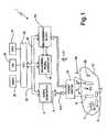
figure 1 shows, in a simplified manner, an electroporation device according to the present invention; - ◆
figure 2 is a flow chart of the operations performed by the electro poration device according to a first embodiment of the invention; - ◆
figure 3 illustrates a signal ratio of current to voltage based on which the control of the electroporating pulse S(t) is performed; and - ◆
figure 4 is a flow chart of the operations performed by the electro poration device according to a second embodiment of the invention. - In
figure 1 ,number 1 indicates an electro - poration device realised according to the present invention. - In particular,
device 1 comprises of asignal generator 3 for producing a stimulating signal S(t) that is amplified by apower amplifier 5 and applied toelectrodes 6, 7 through apower switch 10. Theelectrodes 6,7 are coupled with asubstrate 12 containing living cells C; in particular, thesubstrate 12 may comprise a portion (for instance a tissue) of a living body (plant, animal or man) or may comprise a substrate separate from the living body and contained in a recipient (for instance a culture of animal, plant, bacterial or fungal cells in vitro). - The application of the electroporating signal S(t) to the
electrodes 6,7 causes the creation of an electric field E(t) in thesubstrate 12; such a field E(t) promotes, realises or enhances the permeabilization of the membranes of the cells C rendering possible the introduction of molecules (organic/inorganic) through the membranes of the cells C. Device 1 also comprises ameasuring signal generator 15 coupled with ameasurement block 16 cooperating withelectrodes 6, 7 for the determination of the instantaneous values of the current through thesubstrate 12, the voltage actually applied to thesubstrate 12, and the ratioGT of the current through to voltage applied to the substrate 12 (i.e.GT=ie/vP).Signal generator 3,measuring signal generator 15 andmeasurement block 16 are connected, through acommon BUS 20, with acentral processing unit 23 coupled with interface circuits (not shown), for the communication with peripheral devices, such as avideo display 25,keyboard 26 andprinter 27.- Under the control of the
central processing unit 23 thesignal generator 3 generates a signal S(t) comprising one or a series of pulses which amplitude may be regulated as described in the following. Moreover, thecentral processing unit 23 receives the information related to the VoltageVp of the stimulating signal S(t) applied to theelectrodes 6,7 and the currentie that flows between theelectrodes 6,7 through thesubstrate 12. More particularly,central processing unit 23 detects the instantaneous value of the ratio GT of the currentie flowing through thesubstrate 12 and the voltageVp applied to thesubstrate 12, i.e.:GT =ie/vp. and determines the instantaneous value of the signal S(t). - The knowledge of the above ratio GT is used for controlling stimulating signalS(t) as described in the flow chart of
figure 2 . - Studies and experiments of the applicant have revealed that the curveCGT representing the value of ratio GT in successive instants after the application of the stimulating signal S(t) has a particular waveform that is shown, as non limiting example, in
figure 3 . - In the Cartesian presentation of
figure 3 , Y-axis represents increasing values or ratio GT and X-axis represents successive instants after the start of the application of the stimulating signal S(t); the stimulating signal S(t) being applied from time t = 0 on. - CurveCGT (if permeabilization process is in progress) comprises a first portionCGT-I decreasing from time t = 0 to a time t =Tm wherein an initial minimum is reached, a second portionCGT-II increasing from the timeTm wherein the minimum is reached, and a third portionCGT-III increasing with a very low rate or being substantially flat.
- CurveCGT (if permeabilization is not achieved and permeabilization process in not in progress) comprises a first portionCGT-I decreasing from time t = 0 (the second portionCGT-II increasing from the timeTm is absent) and a third portionCGT-III decreasing with a very low rate or being substantially flat.
- In particular,
block 100 offigure 2 commands the generation of the stimulating signal S(t) and the application of such a signal S(t) to thesubstrate 12 throughelectrodes 6 and 7. Block 100 is followed by ablock 110 that introduces a delayTd so that the stimulating signal S(t) is applied for at least a predetermined period of timeTd; such a period of timeTd having a value so that ratioGT has time to reach and overcome its initial minimum valueTm, in particular ratioGT at the end of delayTd is placed on the second portionCGT-II of curveCGT.Block 110 is followed byblock 120 that determines the instantaneous gradientdG (i.e. instantaneous slope) of the ratio GT after the minimum has been reached, i.e. calculates the derivative of ratio GT,dG =d(GT)/d(t), at the beginning of the second portionCGT-II, or more practically the differencedeltaG=deltaGT/deltaT atTm.Block 120 is followed byblock 130 that compares the calculated instantaneous variationdG of the ratioGT with a reference valuedGref1, for instancedGref1 =1.- In particular, if the calculated instantaneous variationdG of the ratioGT is greater than the reference valuedGref1 (for instance dG > 1)
block 130 is followed byblock 140. If the applied signalS(t) is of too small amplitude to initiate the process of permeabilization the first minimum is not reached within the predetermined time Tm and the gradient at Td is lower than a predetermineddGref2, for instancedGref2=0, thedG atTd is negative (dG<0) andblock 130 is followed byblock 180, whilst if the calculated instantaneous variationdG of the ratioGT is smaller than the reference valuedGref1 and at the same time larger thandGref2 (forinstance 0 < dG <1)block 130 is followed byblock 150. Block 140 performs an urgent correction to the stimulating signal S(t) in order to avoid lesions, damages or irreversible alterations insubstrate 12; to thatregard block 140 is followed by ablock 145 that decreases the amplitude (i.e. the voltage) of the stimulating signal S(t) in order to prevent deterioration in thecells C. Block 145 is then followed byblock 110.Block 150 calculates the average variation ΔG of ratioGT (i.e. the slope calculated over a period of time) in a time interval that is successive to the instant Tm wherein the minimum has been reached and that has a pre-determined time width, for instance ΔG = ΔGT/(T1-Tm) whereinT1 >Tm.Block 150 is followed by ablock 160 that compares the calculated average variation ΔG of ratioGT with a reference interval of ΔG values, for instance a referenceinterval having limits 0 and ΔGobb, wherein ΔGobb, is an expected value of the average variation ΔG above which the corresponding pulses will lead to a too intense permeabilization of the cells and to subsequent damages to the cells.- In
particular block 160 performs the following functions: - if the calculated average variation ΔG of ratioGT falls within the reference interval (for
instance 0 < ΔG < ΔGobb) thenblock 160 is followed by ablock 170; - if the calculated average variation ΔG of ratioGT falls outside the reference interval and it is smaller than both the limits delimiting the interval (for instance ΔG < 0 < ΔGobb) then
block 160 is followed by ablock 180; and - if the calculated average variation ΔG of ratioGT falls outside the reference interval and it is greater than both the limits delimiting the interval (for instance ΔG > ΔGobb > 0) then
block 160 is followed byblock 140. Block 180 increases the voltage of the stimulating signal in order to increase the value of the electric field E(t) applied to thesubstrate 12;block 180 is then followed byblock 110.Block 170 increases the voltage of the stimulating signal to an objective voltageVopt in order to increase the value of the electric field E(t) applied to thesubstrate 12 so that the value of ΔG tends to the expected value ΔGobb.- When the objective voltageVopt has been reached
block 170 is followed by ablock 190 that maintains the stimulating signal at the objective voltageVopt for a predetermined time that is sufficient for achieving a complete electroporation of cells C. - Finally,
block 190 may be followed by ablock 195 that stops the application of pulses of the stimulating signal S(t) or by ablock 200 that, if needed, continues for an extra period of time the application of the stimulating signal of the same or of another value (for example, lower), depending on the molecule to be introduced. Figure 4 shows another preferred embodiment of the present invention. The operations that have not been modified have been indicated by blocks having the same reference numbers, and different operations are indicated with new block and numbers.- More particularly,
block 120 is followed byblock 125 that detects the minimum of the ratio GT. This operation may be realized according know techniques for instance by comparing the instantaneous gradient dG calculated with previously recorded gradients. Block 125 is followed byblock 126 that determines the time Tm at which the minimum detected byblock 125 occurs.Block 126 is followed byblock 127 that compares the detected time Tm with threshold values Ttmin and Ttmax.- More particularly, if the detected Tm occurs before Ttmin (Tm < Ttmin) then
block 126 is followed byblock 140. - If the detected Tm occurs after Ttmax (Tm > Ttmax), then
block 126 is followed byblock 180. - If Tm occurs between Ttmin and Ttmax, then
block 126 is followed byblock 150. Accordinglyblock 130 is eliminated. - In actual use,
electrodes 6, 7 are applied to the substrate 12 (shown schematically inFigure 1 ) containing live cells C. As above outlined, thesubstrate 12 may comprise a tissue portion forming part of a live being (human, animal or plant) or may comprise a tissue or a culture of cells (animal or plant) separated from a live being or a culture of microorganisms (bacteria or fungi, e.g. yeast). Substrate 12 is also applied with a substance (organic or inorganic or biopolymeric) 30 to be introduced into the cells C. Thesubstance 30 may be applied in a number of different ways, some of which are listed below by way of non-limiting examples:- direct application of the substance to the
substrate 12, e.g. by applying to the substrate a fluid containing the substance; - indirect application of the substance, e.g. by introducing the substance into the circulatory system of the tissue portion forming the substrate; and
- injecting the substance, e.g. using
needlelike electrodes 6,7 (not shown), each having an inner conduit containing the substance to be injected into the tissue portion forming the substrate. The substance may also be injected using needles separate from the electrodes. - The
substance 30 introduced may be inorganic or organic or biopolymeric, e.g. - ◆ a nucleic acid;
- ◆ a DNA molecule containing regulatory sequences and sequence coding for therapeutic genes or genes of interest for biomedical or biotechnological purposes;
- ◆ an oligonucleotide, whether natural (phosphodiesters) or modified (inside the backbone of the oligonucleotide, such as phosphosulfates, or at the extremities, by addition of groups to protect the oligonucleotides from digestion of nucleases; the description of oligonucleotide modifications being non-limiting);
- ◆ a protein or peptide, whether natural or genetically or chemically modified, extracted from natural sources or obtained by synthesis, or a molecule simulating the structure of a protein or peptide, whatever its structure;
- ◆ a cytotoxic agent, in particular, the antibiotic bleomycin or the cisplatinum;
- ◆ a penicillin; and
- ◆ other pharmacological agents.
Electroporation device 1 is activated to generate one pulse or a train of pulses (block 100) that are spaced one with respect the other. Electroporation of the cells is therefore started and the ratioGT begins to fall following the first portion of curveCGT (i.e. CGT-I).- Pulses are applied for a period of time (block 110) so that ratioGT reaches its minimum at the timeTm; for instance periodTd may be 15 µs.
- Then to avoid damages in the cells an immediate check is performed (
blocks 120 and 130) to see if, after the minimum has been reached, curveCGT has a too rapid increase (dG > 1); in fact, a too rapid increase after the minimum is a clear indication of irreversible damages to the cells (to that regard see curveCGT-IRREVERSIBLE shown infigure 3 ). In case of a detected indication of irreversible damages a corrective action is performed (blocks 140 and 145) by immediately decreasing the voltage applied thus preventing final damage to the cells. The check ofblocks blocks - In case that no indication of damage is detected then the average slope of curve CGT is scrutinised (block 150) to see if and how the cells are being permeabilized. In particular:
- if the calculated average variation ΔG of ratioGT falls within the reference interval (0 < ΔG < ΔGobb) a situation of normal beginning of the process of permeabilization of the cells is detected and the process of permeabilization is normally continued by increasing the voltage (block 170) so that the value of ΔG tends to the expected value ΔGobb;
- if the calculated average variation ΔG of ratio GT falls outside the reference interval and it is smaller than both limits delimiting the interval (ΔG < 0 < ΔGobb) no beginning of permeabilization is detected (with this regard see curveCGT-NO-PERM) and the voltage is increased (block 180) to start the process of permeabilization; and
- if the calculated average variation ΔG of ratioGT falls outside the reference interval and it is greater than both limits delimiting the interval (AG > ΔGobb > 0) a potentially dangerous situation is detected and a corrective action is consequently performed (
blocks 140 and 145). - The above operation may also be performed by using, instead of the ratioGT =ie/vp, any mathematical combination of currentie and voltagevp.
- Moreover, the above operations may also be performed by using, instead of any mathematical combination of currentie and voltagevp, the value of the currentie. In fact, currentie has a shape that is very similar to the shape of ratioGT presented in
figure 3 if Vp rise times is very fast and if Vp is then constant or almost constant. - In the above case all the operations disclosed with respect to blocks 100-200 directly performed on the currentie. For
instance block 120 determines the instantaneous variationdie of currentie, block 130 compares the instantaneous variationdie with reference values, block 150 calculates an average variation Δie of current ie and block 160 compares the calculated average variation Δie with reference values. - According to the above embodiment, it is necessary a more simple equipment for measure and calculation and the electroporation device provide a stimulating signal extremely "square".
- It is therefore clear that, according to the present invention, the curve CGT is constantly monitored and the stimulating signal is applied in a modified manner according to the detected waveform of an initial portion of curve CGT.
- In particular, the application of the stimulating signal is dependent on the shape of the curve CGT, in particular the slope at particular time points.
- Studies and experiments performed by the applicant have revealed that controlling the process of permeabilization as above outlined, i.e. focusing the analysis in the initial part of the waveform that corresponds to the initial instants wherein the process has been started but the real permeabilization has not still occurred, permits from one side to avoid damages to the cells and from the other side to obtain a good permeabilization of the cells.
Claims (12)
- Electroporation device for the permeabilization of cells (C) contained in a substrate (12) comprising signal generating means (3) for generating a stimulating signal (S (t)) applied by means of electrodes (6,7) to the substrate (12) wherein an electric field (E (t)) permeabilizing the cells membranes is induced;
the device beingcharacterized by comprising:- means for measuring, calculating and monitoring (15,16, 23) the instantaneous value of the ratio (GT) of current (ie) flowing between said electrodes (6,7) and through the substrate (12) and voltage (Vp) of the stimulating signal (S (t)) applied to the substrate (12) by means of said electrodes (6, 7);the curve representing the value of the ratio (GT) in successive instants after the beginning of the application of the stimulating signal (S (t)) comprising a first portion CGT-I decreasing from a time t = 0 corresponding to the beginning to a time t = Tm wherein an initial minimum is reached, a second portion CGT-II increasing from the time Tm wherein the minimum is reached, and a third portion CGT-III increasing with a very low rate or being substantially flat;- said device further comprising controlling means (100-170) for applying the stimulating signal in a controlled manner according to the waveform of an initial portion of said curve CGT;said controlling means (100-170) comprise timing means (110) for applying said stimulating signal for a predetermined period of time Td having a value so that ratio GT has time to reach and overcome its initial minimum value,
said controlling means (100-170) analysing immediately the waveform after the detection of said minimum value CGT to calculate its slope in order to detect indication of irreversible damages in the cells of the substrate, - Device as claimed in claim 1, wherein said controlling means (100-170) comprise hazard detecting means (120) determining the instantaneous gradient (dG) of said ratio (GT) after said minimum has been reached in said curve CGT ; said controlling means further comprise first comparing means (130) for comparing the calculated instantaneous gradient dG with at least a reference value (dcref1) and selecting correcting means (140,145) for performing an urgent correction to the stimulating signal S(t) in order to avoid lesions, damages or irreversible alterations in said substrate (12).
- Device as claimed in claim 2, wherein said correcting means (140,145) decreases the voltage of the stimulating signal S (t) in order to prevent deterioration in the cells (C).
- Device as claimed in any of the preceding claims, wherein said controlling means (100-170) comprise slope determining means (150) calculating the average variation ΔG of said ratio (GT) in a time interval that is successive to the instant Tm wherein said minimum has been reached and that has a pre-determined time width; said controlling means further comprising second comparing means (160) comparing the calculated average variation ΔG of said ratio GT with a reference interval of ΔG values.
- Device as claimed in claim 4, wherein said second comparing means (160) performs the following functions:- if the calculated average variation ΔG of said ratio GT falls within the reference interval (0 < ΔG < ΔGobb) continuing means (170) are selected;- if the calculated average variation ΔG of said ratio GT falls outside the reference interval and it is smaller than both limits delimiting the interval (ΔG < 0 < ΔGobb) adjusting means (180) are selected; and- if the calculated average variation ΔG of said ratio GT falls outside the reference interval and it is greater than both limits delimiting the interval (ΔG > ΔGb > 0) correcting means (140) are selected.
- Device as claimed in claim 5, wherein said adjusting means (180) increase the voltage of the stimulating signal in order to increase the value of the electric field E (t) applied to the substrate (12); said adjusting means (180) subsequently selecting said means for calculating and monitoring (15,16, 23) the instantaneous value of the said ratio (GT) and said controlling means.
- Device as claimed in claim 6, wherein said continuing means (170) increase the voltage of the stimulating signal to an objective voltage Vopt in order to increase the value of the electric field E (t) applied to the substrate (12) so that the value of said average variation ΔG tends to an expected value ΔGobb.
- Device as claimed in any of the preceding claims, wherein said controlling means (100-170) detects (125) the time Tm at which the minimum is reached.
- Device as claimed in claim 8, wherein third comparing means (127) are provided to compare the detected time Tm with threshold values Ttmin and Ttmax ; said third comparing means (127) performing the following operations:- if the detected Tm occurs before Ttmin (Tm < Ttmin) then correcting means (140) are selected;- if the detected Tm occurs after Ttmax (Tm > Ttmax), then adjusting means (180) are selected; and- if the detected Tm occurs between Ttmin and Ttmax, then continuing means (170) are selected.
- Use of a device as described in any of the preceding claims, to extract molecules from the living cells comprised in the substrate.
- Use of a device as described in any of the preceding claims, to introduce molecules into living cells.
- Use of the device as claimed in any of the preceding claims, wherein said molecules comprise one of the following:a DNA or a RNA molecule containing regulatory sequences and sequence coding for therapeutic genes or genes of interest for biomedical or biotechnological purposes;an oligonucleotide, (ribo-or deoxyribo- nucleotide, single or double strand, including the SiRNA), whether natural (phosphodiesters) or modified (inside the backbone of the oligonucleotide, such as phosphosulfates, or at the extremities, by addition of groups to protect the oligonucleotides from digestion of nucleases; a protein or peptide, whether natural or genetically or chemically modified, extracted from natural sources or obtained by synthesis, ora molecule simulating the structure of a protein or peptide, whatever its structure;a cytotoxic agent, in particular, the antibiotic bleomycin or the cisplatinum;a penicillin; and other pharmacological agents.
Applications Claiming Priority (3)
| Application Number | Priority Date | Filing Date | Title |
|---|---|---|---|
| IT2002TO000477AITTO20020477A1 (en) | 2002-06-07 | 2002-06-07 | ELECTROPORATION DEVICE. |
| ITTO20020477 | 2002-06-07 | ||
| PCT/EP2003/005993WO2003104448A1 (en) | 2002-06-07 | 2003-06-10 | Electroporation device |
Publications (2)
| Publication Number | Publication Date |
|---|---|
| EP1511841A1 EP1511841A1 (en) | 2005-03-09 |
| EP1511841B1true EP1511841B1 (en) | 2013-04-17 |
Family
ID=27639139
Family Applications (1)
| Application Number | Title | Priority Date | Filing Date |
|---|---|---|---|
| EP03757041.3AExpired - LifetimeEP1511841B1 (en) | 2002-06-07 | 2003-06-10 | Electroporation device |
Country Status (5)
| Country | Link |
|---|---|
| US (1) | US7625729B2 (en) |
| EP (1) | EP1511841B1 (en) |
| AU (1) | AU2003242648A1 (en) |
| IT (1) | ITTO20020477A1 (en) |
| WO (1) | WO2003104448A1 (en) |
Families Citing this family (4)
| Publication number | Priority date | Publication date | Assignee | Title |
|---|---|---|---|---|
| US20090294290A1 (en)* | 2005-02-15 | 2009-12-03 | Hiroshi Furusawa | Non-Contact Manipulation Device With An Electrode Pair and Manipulation Method Thereof |
| WO2006112870A1 (en)* | 2005-04-19 | 2006-10-26 | Excellin Life Sciences, Inc. | Device and method for controlled electroporation and molecular delivery in cells and tissue |
| WO2007117651A2 (en)* | 2006-04-07 | 2007-10-18 | University Of South Florida | Passive electric field focus system for in vivo and in vitro applications |
| IT202000031379A1 (en) | 2020-12-18 | 2022-06-18 | Curaleaf International Ltd | TOPICAL PHARMACEUTICAL FORMULATION AND METHOD FOR THE TREATMENT OF SYNDROMES ASSOCIATED WITH CHRONIC PELVIC PAIN |
Family Cites Families (5)
| Publication number | Priority date | Publication date | Assignee | Title |
|---|---|---|---|---|
| ATE241933T1 (en)* | 1998-09-30 | 2003-06-15 | Cygnus Therapeutic Systems | METHOD AND DEVICE FOR PREDICTING PHYSIOLOGICAL MEASUREMENT VALUES |
| US6300108B1 (en)* | 1999-07-21 | 2001-10-09 | The Regents Of The University Of California | Controlled electroporation and mass transfer across cell membranes |
| US6403348B1 (en) | 1999-07-21 | 2002-06-11 | The Regents Of The University Of California | Controlled electroporation and mass transfer across cell membranes |
| US6387671B1 (en) | 1999-07-21 | 2002-05-14 | The Regents Of The University Of California | Electrical impedance tomography to control electroporation |
| IT1320186B1 (en) | 2000-04-21 | 2003-11-26 | Igea Srl | ELECTRO-PORTATION DEVICE AND METHOD IN WHICH THE IMPULSE OF THE PULSE OR PULSES IS ESTABLISHED AUTOMATICALLY IN |
- 2002
- 2002-06-07ITIT2002TO000477Apatent/ITTO20020477A1/enunknown
- 2003
- 2003-06-10WOPCT/EP2003/005993patent/WO2003104448A1/ennot_activeApplication Discontinuation
- 2003-06-10EPEP03757041.3Apatent/EP1511841B1/ennot_activeExpired - Lifetime
- 2003-06-10AUAU2003242648Apatent/AU2003242648A1/ennot_activeAbandoned
- 2003-06-10USUS10/517,038patent/US7625729B2/ennot_activeExpired - Lifetime
Also Published As
| Publication number | Publication date |
|---|---|
| AU2003242648A1 (en) | 2003-12-22 |
| ITTO20020477A1 (en) | 2003-12-09 |
| US7625729B2 (en) | 2009-12-01 |
| WO2003104448A1 (en) | 2003-12-18 |
| ITTO20020477A0 (en) | 2002-06-07 |
| US20060057706A1 (en) | 2006-03-16 |
| EP1511841A1 (en) | 2005-03-09 |
Similar Documents
| Publication | Publication Date | Title |
|---|---|---|
| WO2001081533A1 (en) | Electroporation device and method, where amplitude of the electric pulse or pulses is automatically set according to pre-pulse measurement of electric properties of the sample | |
| US11318304B2 (en) | System and method for electroporation controlled by electrical impedance measurements | |
| EP1673140B1 (en) | Constant current electroporation device | |
| Kandušer et al. | Electroporation in biological cell and tissue: an overview | |
| EP1163024A4 (en) | Delivery of macromolecules into cells | |
| EP1274830B1 (en) | Device for electroporation under continuous control of cell permeabilization | |
| US5869326A (en) | Electroporation employing user-configured pulsing scheme | |
| US12127779B2 (en) | Methods, systems, and apparatuses for tissue ablation using a modulated exponential decay pulse | |
| EP1395333A1 (en) | Electroporation device which reduces muscle contraction and pain sensation | |
| WO2016161201A3 (en) | Systems and methods for improved tissue-sensing based electroporation | |
| EP1511841B1 (en) | Electroporation device | |
| Tien et al. | The bilayer lipid membrane (BLM) under electrical fields | |
| Pataro et al. | Mass transfer enhancement by means of electroporation | |
| WO2013126820A1 (en) | Bio-electro reactors with real-time adjustable electric parameters and sequencing programmable power supplies | |
| US20060142688A1 (en) | Programmable apparatus and method for optimizing and real time monitoring of gene transfection based on user configured arbitrary waveform pulsing train | |
| Joersbo et al. | Transient electropermeabilization of barley (Hordeum vulgare L.) microspores to propidium iodide | |
| WO2001080946A1 (en) | Electroporation device with measurement of electrical properties | |
| RU2553947C2 (en) | Training method of biological neuron network of culture grown on multiple-electrode matrix | |
| US20140066836A1 (en) | Electroporation devices | |
| US8000783B2 (en) | Processor controlled voltage-current analysis for nerve and muscle tissues | |
| AU2019396834B2 (en) | Method and system for controlling molecular electrotransfer | |
| Yakovenko | Electroporators based on digital formation of arbitrarily-shaped electroporation pulses | |
| JP3131628B2 (en) | Position control device for electrodes for measuring neuronal activity | |
| WO2005116203A3 (en) | Method and apparatus for bacterial transformation by electroporation with waveforms incorporating pulsed rf between 3 and 125 mhz | |
| CN221956108U (en) | An electrotransfection device |
Legal Events
| Date | Code | Title | Description |
|---|---|---|---|
| PUAI | Public reference made under article 153(3) epc to a published international application that has entered the european phase | Free format text:ORIGINAL CODE: 0009012 | |
| 17P | Request for examination filed | Effective date:20041230 | |
| AK | Designated contracting states | Kind code of ref document:A1 Designated state(s):AT BE BG CH CY CZ DE DK EE ES FI FR GB GR HU IE IT LI LU MC NL PT RO SE SI SK TR | |
| AX | Request for extension of the european patent | Extension state:AL LT LV MK | |
| DAX | Request for extension of the european patent (deleted) | ||
| 17Q | First examination report despatched | Effective date:20090129 | |
| GRAP | Despatch of communication of intention to grant a patent | Free format text:ORIGINAL CODE: EPIDOSNIGR1 | |
| GRAS | Grant fee paid | Free format text:ORIGINAL CODE: EPIDOSNIGR3 | |
| RAP1 | Party data changed (applicant data changed or rights of an application transferred) | Owner name:IGEA S.P.A. | |
| GRAA | (expected) grant | Free format text:ORIGINAL CODE: 0009210 | |
| AK | Designated contracting states | Kind code of ref document:B1 Designated state(s):AT BE BG CH CY CZ DE DK EE ES FI FR GB GR HU IE IT LI LU MC NL PT RO SE SI SK TR | |
| REG | Reference to a national code | Ref country code:GB Ref legal event code:FG4D | |
| REG | Reference to a national code | Ref country code:CH Ref legal event code:EP | |
| REG | Reference to a national code | Ref country code:IE Ref legal event code:FG4D | |
| REG | Reference to a national code | Ref country code:AT Ref legal event code:REF Ref document number:607341 Country of ref document:AT Kind code of ref document:T Effective date:20130515 | |
| REG | Reference to a national code | Ref country code:DE Ref legal event code:R096 Ref document number:60343815 Country of ref document:DE Effective date:20130606 | |
| REG | Reference to a national code | Ref country code:AT Ref legal event code:MK05 Ref document number:607341 Country of ref document:AT Kind code of ref document:T Effective date:20130417 | |
| REG | Reference to a national code | Ref country code:NL Ref legal event code:VDEP Effective date:20130417 | |
| PG25 | Lapsed in a contracting state [announced via postgrant information from national office to epo] | Ref country code:PT Free format text:LAPSE BECAUSE OF FAILURE TO SUBMIT A TRANSLATION OF THE DESCRIPTION OR TO PAY THE FEE WITHIN THE PRESCRIBED TIME-LIMIT Effective date:20130819 Ref country code:GR Free format text:LAPSE BECAUSE OF FAILURE TO SUBMIT A TRANSLATION OF THE DESCRIPTION OR TO PAY THE FEE WITHIN THE PRESCRIBED TIME-LIMIT Effective date:20130718 Ref country code:BE Free format text:LAPSE BECAUSE OF FAILURE TO SUBMIT A TRANSLATION OF THE DESCRIPTION OR TO PAY THE FEE WITHIN THE PRESCRIBED TIME-LIMIT Effective date:20130417 Ref country code:AT Free format text:LAPSE BECAUSE OF FAILURE TO SUBMIT A TRANSLATION OF THE DESCRIPTION OR TO PAY THE FEE WITHIN THE PRESCRIBED TIME-LIMIT Effective date:20130417 Ref country code:SI Free format text:LAPSE BECAUSE OF FAILURE TO SUBMIT A TRANSLATION OF THE DESCRIPTION OR TO PAY THE FEE WITHIN THE PRESCRIBED TIME-LIMIT Effective date:20130417 Ref country code:FI Free format text:LAPSE BECAUSE OF FAILURE TO SUBMIT A TRANSLATION OF THE DESCRIPTION OR TO PAY THE FEE WITHIN THE PRESCRIBED TIME-LIMIT Effective date:20130417 Ref country code:SE Free format text:LAPSE BECAUSE OF FAILURE TO SUBMIT A TRANSLATION OF THE DESCRIPTION OR TO PAY THE FEE WITHIN THE PRESCRIBED TIME-LIMIT Effective date:20130417 Ref country code:ES Free format text:LAPSE BECAUSE OF FAILURE TO SUBMIT A TRANSLATION OF THE DESCRIPTION OR TO PAY THE FEE WITHIN THE PRESCRIBED TIME-LIMIT Effective date:20130728 | |
| PG25 | Lapsed in a contracting state [announced via postgrant information from national office to epo] | Ref country code:BG Free format text:LAPSE BECAUSE OF FAILURE TO SUBMIT A TRANSLATION OF THE DESCRIPTION OR TO PAY THE FEE WITHIN THE PRESCRIBED TIME-LIMIT Effective date:20130717 Ref country code:CY Free format text:LAPSE BECAUSE OF FAILURE TO SUBMIT A TRANSLATION OF THE DESCRIPTION OR TO PAY THE FEE WITHIN THE PRESCRIBED TIME-LIMIT Effective date:20130417 | |
| PG25 | Lapsed in a contracting state [announced via postgrant information from national office to epo] | Ref country code:DK Free format text:LAPSE BECAUSE OF FAILURE TO SUBMIT A TRANSLATION OF THE DESCRIPTION OR TO PAY THE FEE WITHIN THE PRESCRIBED TIME-LIMIT Effective date:20130417 Ref country code:SK Free format text:LAPSE BECAUSE OF FAILURE TO SUBMIT A TRANSLATION OF THE DESCRIPTION OR TO PAY THE FEE WITHIN THE PRESCRIBED TIME-LIMIT Effective date:20130417 Ref country code:MC Free format text:LAPSE BECAUSE OF FAILURE TO SUBMIT A TRANSLATION OF THE DESCRIPTION OR TO PAY THE FEE WITHIN THE PRESCRIBED TIME-LIMIT Effective date:20130417 Ref country code:EE Free format text:LAPSE BECAUSE OF FAILURE TO SUBMIT A TRANSLATION OF THE DESCRIPTION OR TO PAY THE FEE WITHIN THE PRESCRIBED TIME-LIMIT Effective date:20130417 Ref country code:CZ Free format text:LAPSE BECAUSE OF FAILURE TO SUBMIT A TRANSLATION OF THE DESCRIPTION OR TO PAY THE FEE WITHIN THE PRESCRIBED TIME-LIMIT Effective date:20130417 | |
| REG | Reference to a national code | Ref country code:CH Ref legal event code:PL | |
| PLBE | No opposition filed within time limit | Free format text:ORIGINAL CODE: 0009261 | |
| STAA | Information on the status of an ep patent application or granted ep patent | Free format text:STATUS: NO OPPOSITION FILED WITHIN TIME LIMIT | |
| PG25 | Lapsed in a contracting state [announced via postgrant information from national office to epo] | Ref country code:RO Free format text:LAPSE BECAUSE OF FAILURE TO SUBMIT A TRANSLATION OF THE DESCRIPTION OR TO PAY THE FEE WITHIN THE PRESCRIBED TIME-LIMIT Effective date:20130417 Ref country code:NL Free format text:LAPSE BECAUSE OF FAILURE TO SUBMIT A TRANSLATION OF THE DESCRIPTION OR TO PAY THE FEE WITHIN THE PRESCRIBED TIME-LIMIT Effective date:20130417 | |
| 26N | No opposition filed | Effective date:20140120 | |
| REG | Reference to a national code | Ref country code:IE Ref legal event code:MM4A | |
| PG25 | Lapsed in a contracting state [announced via postgrant information from national office to epo] | Ref country code:CH Free format text:LAPSE BECAUSE OF NON-PAYMENT OF DUE FEES Effective date:20130630 Ref country code:LI Free format text:LAPSE BECAUSE OF NON-PAYMENT OF DUE FEES Effective date:20130630 Ref country code:IE Free format text:LAPSE BECAUSE OF NON-PAYMENT OF DUE FEES Effective date:20130610 | |
| REG | Reference to a national code | Ref country code:DE Ref legal event code:R097 Ref document number:60343815 Country of ref document:DE Effective date:20140120 | |
| PG25 | Lapsed in a contracting state [announced via postgrant information from national office to epo] | Ref country code:TR Free format text:LAPSE BECAUSE OF FAILURE TO SUBMIT A TRANSLATION OF THE DESCRIPTION OR TO PAY THE FEE WITHIN THE PRESCRIBED TIME-LIMIT Effective date:20130417 | |
| PG25 | Lapsed in a contracting state [announced via postgrant information from national office to epo] | Ref country code:HU Free format text:LAPSE BECAUSE OF FAILURE TO SUBMIT A TRANSLATION OF THE DESCRIPTION OR TO PAY THE FEE WITHIN THE PRESCRIBED TIME-LIMIT; INVALID AB INITIO Effective date:20030610 Ref country code:LU Free format text:LAPSE BECAUSE OF NON-PAYMENT OF DUE FEES Effective date:20130610 | |
| REG | Reference to a national code | Ref country code:FR Ref legal event code:PLFP Year of fee payment:14 | |
| REG | Reference to a national code | Ref country code:FR Ref legal event code:PLFP Year of fee payment:15 | |
| REG | Reference to a national code | Ref country code:FR Ref legal event code:PLFP Year of fee payment:16 | |
| PGFP | Annual fee paid to national office [announced via postgrant information from national office to epo] | Ref country code:IT Payment date:20220518 Year of fee payment:20 Ref country code:GB Payment date:20220519 Year of fee payment:20 Ref country code:FR Payment date:20220519 Year of fee payment:20 Ref country code:DE Payment date:20220518 Year of fee payment:20 | |
| REG | Reference to a national code | Ref country code:DE Ref legal event code:R071 Ref document number:60343815 Country of ref document:DE | |
| REG | Reference to a national code | Ref country code:GB Ref legal event code:PE20 Expiry date:20230609 | |
| P01 | Opt-out of the competence of the unified patent court (upc) registered | Effective date:20230629 | |
| PG25 | Lapsed in a contracting state [announced via postgrant information from national office to epo] | Ref country code:GB Free format text:LAPSE BECAUSE OF EXPIRATION OF PROTECTION Effective date:20230609 |