EP1511575B1 - Adjustable flow texture sprayer with peristaltic pump - Google Patents
Adjustable flow texture sprayer with peristaltic pumpDownload PDFInfo
- Publication number
- EP1511575B1 EP1511575B1EP03737034AEP03737034AEP1511575B1EP 1511575 B1EP1511575 B1EP 1511575B1EP 03737034 AEP03737034 AEP 03737034AEP 03737034 AEP03737034 AEP 03737034AEP 1511575 B1EP1511575 B1EP 1511575B1
- Authority
- EP
- European Patent Office
- Prior art keywords
- sprayer
- tubing
- attached
- hose
- couplings
- Prior art date
- Legal status (The legal status is an assumption and is not a legal conclusion. Google has not performed a legal analysis and makes no representation as to the accuracy of the status listed.)
- Expired - Lifetime
Links
Images


Classifications
- B—PERFORMING OPERATIONS; TRANSPORTING
- B05—SPRAYING OR ATOMISING IN GENERAL; APPLYING FLUENT MATERIALS TO SURFACES, IN GENERAL
- B05B—SPRAYING APPARATUS; ATOMISING APPARATUS; NOZZLES
- B05B9/00—Spraying apparatus for discharge of liquids or other fluent material, without essentially mixing with gas or vapour
- B05B9/03—Spraying apparatus for discharge of liquids or other fluent material, without essentially mixing with gas or vapour characterised by means for supplying liquid or other fluent material
- B—PERFORMING OPERATIONS; TRANSPORTING
- B05—SPRAYING OR ATOMISING IN GENERAL; APPLYING FLUENT MATERIALS TO SURFACES, IN GENERAL
- B05B—SPRAYING APPARATUS; ATOMISING APPARATUS; NOZZLES
- B05B7/00—Spraying apparatus for discharge of liquids or other fluent materials from two or more sources, e.g. of liquid and air, of powder and gas
- B05B7/24—Spraying apparatus for discharge of liquids or other fluent materials from two or more sources, e.g. of liquid and air, of powder and gas with means, e.g. a container, for supplying liquid or other fluent material to a discharge device
- B05B7/2489—Spraying apparatus for discharge of liquids or other fluent materials from two or more sources, e.g. of liquid and air, of powder and gas with means, e.g. a container, for supplying liquid or other fluent material to a discharge device an atomising fluid, e.g. a gas, being supplied to the discharge device
- B—PERFORMING OPERATIONS; TRANSPORTING
- B05—SPRAYING OR ATOMISING IN GENERAL; APPLYING FLUENT MATERIALS TO SURFACES, IN GENERAL
- B05B—SPRAYING APPARATUS; ATOMISING APPARATUS; NOZZLES
- B05B9/00—Spraying apparatus for discharge of liquids or other fluent material, without essentially mixing with gas or vapour
- B05B9/03—Spraying apparatus for discharge of liquids or other fluent material, without essentially mixing with gas or vapour characterised by means for supplying liquid or other fluent material
- B05B9/04—Spraying apparatus for discharge of liquids or other fluent material, without essentially mixing with gas or vapour characterised by means for supplying liquid or other fluent material with pressurised or compressible container; with pump
- B05B9/0403—Spraying apparatus for discharge of liquids or other fluent material, without essentially mixing with gas or vapour characterised by means for supplying liquid or other fluent material with pressurised or compressible container; with pump with pumps for liquids or other fluent material
- B05B9/042—Spraying apparatus for discharge of liquids or other fluent material, without essentially mixing with gas or vapour characterised by means for supplying liquid or other fluent material with pressurised or compressible container; with pump with pumps for liquids or other fluent material with peristaltic pumps
- F—MECHANICAL ENGINEERING; LIGHTING; HEATING; WEAPONS; BLASTING
- F04—POSITIVE - DISPLACEMENT MACHINES FOR LIQUIDS; PUMPS FOR LIQUIDS OR ELASTIC FLUIDS
- F04B—POSITIVE-DISPLACEMENT MACHINES FOR LIQUIDS; PUMPS
- F04B17/00—Pumps characterised by combination with, or adaptation to, specific driving engines or motors
- F04B17/06—Mobile combinations
- F—MECHANICAL ENGINEERING; LIGHTING; HEATING; WEAPONS; BLASTING
- F04—POSITIVE - DISPLACEMENT MACHINES FOR LIQUIDS; PUMPS FOR LIQUIDS OR ELASTIC FLUIDS
- F04B—POSITIVE-DISPLACEMENT MACHINES FOR LIQUIDS; PUMPS
- F04B41/00—Pumping installations or systems specially adapted for elastic fluids
- F04B41/06—Combinations of two or more pumps
- F—MECHANICAL ENGINEERING; LIGHTING; HEATING; WEAPONS; BLASTING
- F04—POSITIVE - DISPLACEMENT MACHINES FOR LIQUIDS; PUMPS FOR LIQUIDS OR ELASTIC FLUIDS
- F04B—POSITIVE-DISPLACEMENT MACHINES FOR LIQUIDS; PUMPS
- F04B43/00—Machines, pumps, or pumping installations having flexible working members
- F04B43/12—Machines, pumps, or pumping installations having flexible working members having peristaltic action
- F04B43/1215—Machines, pumps, or pumping installations having flexible working members having peristaltic action having no backing plate (deforming of the tube only by rollers)
- F—MECHANICAL ENGINEERING; LIGHTING; HEATING; WEAPONS; BLASTING
- F04—POSITIVE - DISPLACEMENT MACHINES FOR LIQUIDS; PUMPS FOR LIQUIDS OR ELASTIC FLUIDS
- F04B—POSITIVE-DISPLACEMENT MACHINES FOR LIQUIDS; PUMPS
- F04B2205/00—Fluid parameters
- F04B2205/09—Flow through the pump
Definitions
- Texture sprayershave traditionally ranged from simple guns having top-mounted hoppers (hopper guns) to progressive cavity pumps which can pump large amounts of material substantial distances at substantial cost and weight.
- Prior art peristaltic pumpsare provided with a rotor having two (or more) rollers, the rotor being capable of rotation in either direction while a tube or hose is stretched across a distance. This creates kinks or closures in the tube at the points of roller contact. As the rotor revolves, the kinks travel with the rollers providing a positive displacement of the fluid contained between the kinks. Most such pumps provide a follower plate which sandwiches the hose between itself and the rollers.
- FR 1213896discloses a pump comprising a support, a tube attached to the support, a rotor and a plurality of cams attached to the rotor.
- the rotormay be driven by a motor.
- the rotoris pivotally mounted to the support via a movable arm and a spring is mounted between the support and the movable arm so as to pull the rotor against the tube.
- FR 1213896also discloses a pump in which a U-shaped length of tubing is wrapped around a rotor comprising two rollers. The ends of the tubing are attached to a frame and the rotor is fixed to the frame by an arm.
- a sprayer for application of viscous materials such as texturecomprising:
- a cartcontains one or more adjustable flow peristaltic pumps, a motor (electric or gas), a material supply hopper and a flow control device.
- a double-ended motor shaftmay be provided wherein one end drive the peristaltic pump and the other end drives an air compressor.
- This apparatusmay also be provided without the compressor where the user will supply atomization air.
- a texture spray gunis provided with a small hop so that it may be used either independently or with the cart mounted material supply.
- Another versionmay be provided with a separate compressor having its own motor for independent operation of material and air.
- the peristaltic pumpprovides a unique vibration which enhances the flow of high viscosity materials such as texture by loosening the bond between the hose and the high viscosity materials as well as self-cleaning the hopper.
- the pumpmay be run forward or reverse with reverse being used to empty the hose or transfer material.
- the hose retention mechanism on the peristaltic pumpconsists of a coupled hose, a hose retainer plate, a mounting plate and a retainer screw.
- a hose with couplingsslides onto each end of the hose retainer plate.
- the hose retainer plateis secured to a mounting plate or surface with a fastener while the hose couplings protrude through the surface of the mounting plate for access.
- the hose retainer platesupports the downward loads imposed by the peristaltic pump while the mounting plate or surface keeps the coupled hose in proper alignment in the pump. Matching the profile of the fittings (e.g. hexagon) with the opening of the mounting plate or surface prevents rotation of the fittings when mating hoses are attached with threaded couplings.
- the distance over which the hose is stretchedis made variable or adjustable so that a variable rate of flow may be achieved.
- the flowis varied by an adjuster that pulls the tubing closer or farther away from the center of the rotor.
- hose tension Tis increased thereby decreasing leakage QL at the points of roller contact.
- the relationship between output/input pressure P, tube or hose tension T, fluid viscosity V and tube/hose material choiceswill determine the pump efficiency. Because of these factors, the pump can run anywhere from zero to 100% volumetric efficiency.
- leakage volume QLbecomes equal to the displacement volume (2Q x rpm) thus preventing overpressurization.
- the self-compensating pump designeliminates the need for expensive motor speed and/or shutoff controls as well as eliminating high current motor starts (allowing the use of a standard 15 amp outlet).
- the instant inventionis a small, relatively inexpensive and self-contained texture sprayer.
- a cart 12contains one or more adjustable flow peristaltic pumps 14, a motor 16 (electric or gas), a material supply hopper 18 and a flow control device 20 such as a spray gun or dispense valve.
- a double-ended motor shaftmay be provided wherein one end drive the peristaltic pump 14 and the other end drives an air compressor 22.
- this apparatusmay also be provided without the compressor where the user will supply atomization air.
- a texture spray gunis provided with a small hopper 20a so that it may be used either independently or with the cart mounted material supply.
- Another versionmay be provided with a separate compressor having its own motor for independent operation of material and air.
- the peristaltic pump 14provides a unique vibration which enhances the flow of high viscosity materials such as texture by loosening the bond between the hose 24 and the high viscosity materials as well as self-cleaning the hopper 18.
- the pump 14may be run forward or reverse with reverse being used to empty the hose or transfer material.
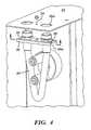
- the hose retention mechanism 26 on the peristaltic pump 14consists of a coupled hose 28, a hose retainer plate 30, a mounting plate 32 and a retainer screw 34.
- a hose with couplings 36slides onto each end 30a of the hose retainer plate 30.
- the hose retainer plate 30is secured to a mounting plate or surface 32 with a fastener 34 while the hose couplings 36 protrude through the surface of the mounting plate 32 for access.
- the hose retainer plate 30supports the downward loads imposed by the peristaltic pump 14 while the mounting plate or surface 32 keeps the coupled hose 28 in proper alignment in the pump 14.
- Matching the profile of the fittings 36e.g. hexagon
- the opening 32a of the mounting plate or surface 32prevents rotation of the fittings 36 when mating hoses 38 are attached with threaded couplings 38a.
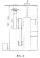
- the distance D over which the hose 28 is stretchedis made variable or adjustable so that a variable rate of flow may be achieved.
- the flowis varied by an adjuster 40 that pulls the tubing 28 closer or farther away from the center of the rotor 42 by raising and lowering the mounting plate 32 relative to the frame 12, rotor 42 and rollers 44.
- the preferred adjuster 46is a variable force device for varying the amount of tension on the tubing 28 and the resulting flow.
- Such devicemay be a fluid (air or liquid) cylinder which may have, if desired, a separate pressure adjustment 48 for controlling the amount of force applied and accordingly the flow rate.
- the adjuster 46may also be a solenoid, adjustable spring or other art recognized force generator.
- hose tension Tis increased thereby decreasing leakage QL at the points of roller 44 contact.
- the relationship between output/input pressure P, tube or hose tension T, fluid viscosity V and tube/hose material choiceswill determine the pump efficiency. Because of these factors, the pump can run anywhere from zero to 100% volumetric efficiency.
- leakage volume QLbecomes equal to the displacement volume (2Q x rpm) thus preventing overpressurization.
- the self-compensating pump designeliminates the need for expensive motor speed and/or shutoff controls as well as eliminating high current motor starts (allowing the use of a standard 15 amp outlet).
Landscapes
- Engineering & Computer Science (AREA)
- Mechanical Engineering (AREA)
- General Engineering & Computer Science (AREA)
- Reciprocating Pumps (AREA)
- Catching Or Destruction (AREA)
- Nozzles (AREA)
Description
- Texture sprayers have traditionally ranged from simple guns having top-mounted hoppers (hopper guns) to progressive cavity pumps which can pump large amounts of material substantial distances at substantial cost and weight.
- Prior art peristaltic pumps are provided with a rotor having two (or more) rollers, the rotor being capable of rotation in either direction while a tube or hose is stretched across a distance. This creates kinks or closures in the tube at the points of roller contact. As the rotor revolves, the kinks travel with the rollers providing a positive displacement of the fluid contained between the kinks. Most such pumps provide a follower plate which sandwiches the hose between itself and the rollers.
FR 1213896 FR 1213896 - According to an aspect of the present invention, there is provided a sprayer for application of viscous materials such as texture, said sprayer comprising:
- a frame; a loop of tubing having first and second ends and being attached to said frame; a motor, said motor having a shaft with a rotor attached thereto, said motor being pivotably attached to said frame to vary the distance between said shaft and said first and second tubing ends; a plurality of rollers attached to said rotor and engaging said tubing; and characterised by a force generator attached between said motor and said frame, the force generator being adapted to vary the force with which said rollers contact said tubing.
- It is a desire to have a small, relatively inexpensive and self-contained texture sprayer. A cart contains one or more adjustable flow peristaltic pumps, a motor (electric or gas), a material supply hopper and a flow control device. A double-ended motor shaft may be provided wherein one end drive the peristaltic pump and the other end drives an air compressor.
- This apparatus may also be provided without the compressor where the user will supply atomization air. A texture spray gun is provided with a small hop so that it may be used either independently or with the cart mounted material supply. Another version may be provided with a separate compressor having its own motor for independent operation of material and air.
- It has been found that the peristaltic pump provides a unique vibration which enhances the flow of high viscosity materials such as texture by loosening the bond between the hose and the high viscosity materials as well as self-cleaning the hopper. The pump may be run forward or reverse with reverse being used to empty the hose or transfer material.
- The hose retention mechanism on the peristaltic pump consists of a coupled hose, a hose retainer plate, a mounting plate and a retainer screw. A hose with couplings slides onto each end of the hose retainer plate. The hose retainer plate is secured to a mounting plate or surface with a fastener while the hose couplings protrude through the surface of the mounting plate for access. The hose retainer plate supports the downward loads imposed by the peristaltic pump while the mounting plate or surface keeps the coupled hose in proper alignment in the pump. Matching the profile of the fittings (e.g. hexagon) with the opening of the mounting plate or surface prevents rotation of the fittings when mating hoses are attached with threaded couplings.
- In the peristaltic pump of the instant invention, the distance over which the hose is stretched is made variable or adjustable so that a variable rate of flow may be achieved. The flow is varied by an adjuster that pulls the tubing closer or farther away from the center of the rotor. As the distance D from the mounting point increases, hose tension T is increased thereby decreasing leakage QL at the points of roller contact. The relationship between output/input pressure P, tube or hose tension T, fluid viscosity V and tube/hose material choices will determine the pump efficiency. Because of these factors, the pump can run anywhere from zero to 100% volumetric efficiency.
- When the spray gun or dispense valve is closed (no material flow) and pump running, leakage volume QL becomes equal to the displacement volume (2Q x rpm) thus preventing overpressurization. The self-compensating pump design eliminates the need for expensive motor speed and/or shutoff controls as well as eliminating high current motor starts (allowing the use of a standard 15 amp outlet).
- These and other objects and advantages of the invention will appear more fully from the following description made in conjunction with the accompanying drawings wherein like reference characters refer to the same or similar parts throughout the several views.
Figure 1 is a front perspective view showing the sprayer of the instant invention without a compressor.Figure 2 is a front perspective view showing the sprayer of the instant invention with a compressor.Figure 3 is an exploded view showing hose retention mechanism of the sprayer of the instant invention.Figure 4 is an front perspective view showing hose retention mechanism of the sprayer of the instant invention.Figure 5 is an side plan view showing hose pressure adjustment mechanism of the sprayer of the instant invention.Figure 6 is an front plan view showing hose pressure adjustment mechanism of the sprayer of the instant invention.Figure 7 is an exploded view of the preferred embodiment.- The instant invention, generally designated 10, is a small, relatively inexpensive and self-contained texture sprayer. A
cart 12 contains one or more adjustable flowperistaltic pumps 14, a motor 16 (electric or gas), amaterial supply hopper 18 and aflow control device 20 such as a spray gun or dispense valve. A double-ended motor shaft may be provided wherein one end drive theperistaltic pump 14 and the other end drives anair compressor 22. - As shown in
Figure 1 , this apparatus may also be provided without the compressor where the user will supply atomization air. A texture spray gun is provided with asmall hopper 20a so that it may be used either independently or with the cart mounted material supply. Another version may be provided with a separate compressor having its own motor for independent operation of material and air. - It has been found that the
peristaltic pump 14 provides a unique vibration which enhances the flow of high viscosity materials such as texture by loosening the bond between thehose 24 and the high viscosity materials as well as self-cleaning thehopper 18. Thepump 14 may be run forward or reverse with reverse being used to empty the hose or transfer material. - The
hose retention mechanism 26 on theperistaltic pump 14 consists of a coupledhose 28, ahose retainer plate 30, amounting plate 32 and aretainer screw 34. A hose withcouplings 36 slides onto eachend 30a of thehose retainer plate 30. Thehose retainer plate 30 is secured to a mounting plate orsurface 32 with afastener 34 while thehose couplings 36 protrude through the surface of themounting plate 32 for access. Thehose retainer plate 30 supports the downward loads imposed by theperistaltic pump 14 while the mounting plate orsurface 32 keeps the coupledhose 28 in proper alignment in thepump 14. Matching the profile of the fittings 36 (e.g. hexagon) with the opening 32a of the mounting plate orsurface 32 prevents rotation of thefittings 36 whenmating hoses 38 are attached with threadedcouplings 38a. - In the
peristaltic pump 14 of the instant invention, the distance D over which thehose 28 is stretched is made variable or adjustable so that a variable rate of flow may be achieved. The flow is varied by anadjuster 40 that pulls thetubing 28 closer or farther away from the center of therotor 42 by raising and lowering themounting plate 32 relative to theframe 12,rotor 42 androllers 44. - The
preferred adjuster 46 is a variable force device for varying the amount of tension on thetubing 28 and the resulting flow. Such device may be a fluid (air or liquid) cylinder which may have, if desired, aseparate pressure adjustment 48 for controlling the amount of force applied and accordingly the flow rate. Theadjuster 46 may also be a solenoid, adjustable spring or other art recognized force generator. - As the distance D from the mounting point increases, hose tension T is increased thereby decreasing leakage QL at the points of
roller 44 contact. The relationship between output/input pressure P, tube or hose tension T, fluid viscosity V and tube/hose material choices will determine the pump efficiency. Because of these factors, the pump can run anywhere from zero to 100% volumetric efficiency. - When the spray gun or dispense
valve 20 is closed (no material flow) and pump 14 running, leakage volume QL becomes equal to the displacement volume (2Q x rpm) thus preventing overpressurization. The self-compensating pump design eliminates the need for expensive motor speed and/or shutoff controls as well as eliminating high current motor starts (allowing the use of a standard 15 amp outlet). - It is contemplated that various changes and modifications may be made to the texture sprayer without departing from the invention as defined by the following claims.
Claims (6)
- A sprayer (10) for application of viscous materials such as texture, said sprayer (10) comprising:a frame (12);a loop of tubing (28) having first and second ends and being attached to said frame (12);a motor (16), said motor (16) having a shaft with a rotor (42) attached thereto;a plurality of rollers (44) attached to said rotor (42) and engaging said tubing (28);
characterised by said motor (16) being pivotably attached to said frame (12) to vary the distance between said shaft and said first and second tubing ends; anda force generator (46) attached between said motor (16) and said frame (12), the force generator (46) being adapted to vary the force with which said rollers (44) contact said tubing (28). - The sprayer (10) for application of viscous materials of claim 1 wherein said force generator (46) comprises an air cylinder.
- The sprayer (10) for application of viscous materials of claim 2 wherein said force generator (46) comprises a pressure regulator (48) attached to said air cylinder.
- The sprayer (10) for application of viscous materials of claim 1 wherein said tubing (28) is attached at one of said ends to a source of viscous material (18) and at the other of said ends to an application device (20).
- The sprayer (10) for application of viscous materials of claim 1 wherein said tubing (28) has couplings (36) at said ends and further comprising a tubing retention mechanism (26) comprising:a mounting plate (32); anda hose retainer plate (30), said couplings (36) sliding onto each end of said hose retainer plate (30) with said couplings (36) protruding through the surface of said mounting plate (32) for access and said retainer plate (30) supporting the loads imposed by said rollers (44).
- The sprayer (10) for application of viscous materials of claim 5 wherein said couplings (36) comprise a profile and said mounting plate (32) comprises openings (32a) to match said profile of said couplings (36) to prevent rotation of said couplings (36) when tubing (28) is attached.
Applications Claiming Priority (5)
| Application Number | Priority Date | Filing Date | Title |
|---|---|---|---|
| US38908802P | 2002-06-13 | 2002-06-13 | |
| US389088P | 2002-06-13 | ||
| US44060403P | 2003-01-16 | 2003-01-16 | |
| US440604P | 2003-01-16 | ||
| PCT/US2003/018547WO2003106042A1 (en) | 2002-06-13 | 2003-06-13 | Adjustable flow texture sprayer with peristaltic pump |
Publications (3)
| Publication Number | Publication Date |
|---|---|
| EP1511575A1 EP1511575A1 (en) | 2005-03-09 |
| EP1511575A4 EP1511575A4 (en) | 2007-01-03 |
| EP1511575B1true EP1511575B1 (en) | 2009-01-14 |
Family
ID=29740099
Family Applications (1)
| Application Number | Title | Priority Date | Filing Date |
|---|---|---|---|
| EP03737034AExpired - LifetimeEP1511575B1 (en) | 2002-06-13 | 2003-06-13 | Adjustable flow texture sprayer with peristaltic pump |
Country Status (7)
| Country | Link |
|---|---|
| US (1) | US20050254879A1 (en) |
| EP (1) | EP1511575B1 (en) |
| KR (1) | KR20050013569A (en) |
| CN (1) | CN100421812C (en) |
| AU (1) | AU2003238010A1 (en) |
| DE (1) | DE60325850D1 (en) |
| WO (1) | WO2003106042A1 (en) |
Families Citing this family (29)
| Publication number | Priority date | Publication date | Assignee | Title |
|---|---|---|---|---|
| US7731104B2 (en) | 2006-04-26 | 2010-06-08 | Wagner Spray Tech Corporation | Texture sprayer |
| US7980487B2 (en)* | 2006-06-12 | 2011-07-19 | Titan Tool, Inc. | Texture sprayer |
| USD572795S1 (en) | 2006-06-12 | 2008-07-08 | Titan Tool, Inc. | Texture sprayer |
| US20080279610A1 (en) | 2007-05-07 | 2008-11-13 | Bober Andrew M | Floor finish applicator |
| US8246263B2 (en) | 2007-07-20 | 2012-08-21 | Diversey, Inc. | Floor finish applicator |
| USD580605S1 (en) | 2007-07-20 | 2008-11-11 | Johnsondiversey, Inc. | Floor finish applicator |
| US20110079321A1 (en)* | 2008-05-08 | 2011-04-07 | Mattson Barry W | Texture hopper |
| KR100908669B1 (en)* | 2008-05-15 | 2009-07-21 | 박선배 | Constant pressure liquid spray |
| FR2931838B1 (en) | 2008-06-02 | 2010-06-11 | Millipore Corp | INSTALLATION FOR TREATING A BIOLOGICAL LIQUID. |
| FR2940145B1 (en)* | 2008-12-24 | 2011-03-25 | Millipore Corp | TROLLEY AND INSTALLATION FOR TREATING A BIOLOGICAL LIQUID |
| FR2941385B1 (en) | 2009-01-23 | 2011-04-01 | Millipore Corp | METHOD FOR PROVIDING A CIRCUIT FOR BIOLOGICAL LIQUID AND CIRCUIT OBTAINED |
| US8651397B2 (en) | 2009-03-09 | 2014-02-18 | Techtronic Power Tools Technology Limited | Paint sprayer |
| US20110185539A1 (en)* | 2009-09-09 | 2011-08-04 | Mattson Barry W | Multiple position handle |
| FR2955119B1 (en) | 2010-01-13 | 2012-12-28 | Millipore Corp | CIRCUIT FOR BIOLOGICAL LIQUID |
| FR2960796B1 (en) | 2010-06-08 | 2014-01-24 | Millipore Corp | DEVICE FOR A PLANT FOR TREATING BIOLOGICAL LIQUID |
| FR2960794B1 (en) | 2010-06-08 | 2012-07-27 | Millipore Corp | DEVICE FOR A PLANT FOR TREATING BIOLOGICAL LIQUID |
| FR2960795B1 (en) | 2010-06-08 | 2012-07-27 | Millipore Corp | DEVICE FOR A PLANT FOR TREATING BIOLOGICAL LIQUID |
| FR2961711B1 (en) | 2010-06-23 | 2012-08-17 | Millipore Corp | POCKET FOR CIRCUIT OF A BIOLOGICAL LIQUID TREATMENT FACILITY |
| FR2961713B1 (en) | 2010-06-23 | 2012-08-10 | Millipore Corp | POCKET FOR CIRCUIT OF A BIOLOGICAL LIQUID TREATMENT FACILITY |
| FR2963573B1 (en)* | 2010-08-03 | 2012-08-31 | Millipore Corp | PUMPING TROLLEY FOR A BIOLOGICAL LIQUID TREATMENT FACILITY |
| FR2973396B1 (en) | 2011-03-28 | 2013-05-10 | Millipore Corp | FACILITY FOR TREATING BIOLOGICAL LIQUID |
| FR2993572B1 (en) | 2012-07-23 | 2016-04-15 | Emd Millipore Corp | CIRCUIT FOR BIOLOGICAL LIQUID COMPRISING A PINCH VALVE |
| CN103122848B (en)* | 2013-02-01 | 2016-01-20 | 深圳麦科田生物医疗技术有限公司 | A kind of infusion pump |
| US10046351B2 (en)* | 2014-07-14 | 2018-08-14 | Graco Minnesota Inc. | Material dispense tracking and control |
| CN106994419B (en)* | 2016-01-22 | 2020-09-18 | 固瑞克明尼苏达有限公司 | Hose bracket for texture sprayer |
| US10670006B2 (en)* | 2016-01-22 | 2020-06-02 | Graco Minnesota Inc. | Hose bracket for texture sprayer |
| US10814340B2 (en)* | 2016-01-22 | 2020-10-27 | Graco Minnesota Inc. | Flow-based control for texture sprayer |
| US20170212750A1 (en)* | 2016-01-22 | 2017-07-27 | Rigado, LLC | Compressed binary patching over wireless network |
| CN107269504B (en)* | 2017-08-16 | 2020-01-03 | 保定准择恒流泵制造有限公司 | Peristaltic pump |
Family Cites Families (53)
| Publication number | Priority date | Publication date | Assignee | Title |
|---|---|---|---|---|
| US1335872A (en)* | 1920-04-06 | Muffler | ||
| US2406485A (en)* | 1944-05-05 | 1946-08-27 | Univ Tennessee Res Corp | Hose pump |
| US2820672A (en)* | 1956-07-17 | 1958-01-21 | Lee Mart Mfg Co | Apparatus for controllably applying semifluid and pasty materials |
| FR1213896A (en)* | 1958-11-03 | 1960-04-05 | Soft-walled rotary pump or motor system | |
| US3023967A (en)* | 1961-01-30 | 1962-03-06 | Us Mineral Wool Company | Machine for projecting fibers |
| US3172367A (en)* | 1963-01-08 | 1965-03-09 | Technicon Instr | Roller type pump |
| SE317466B (en)* | 1966-08-01 | 1969-11-17 | Biotec Ab | |
| US3483092A (en)* | 1966-12-19 | 1969-12-09 | Detrex Chem Ind | Recovery of a volatile organic solvent by distillation with solvent feed flow responsive to still temperature |
| US3447478A (en)* | 1967-03-03 | 1969-06-03 | Miles Lab | Peristaltic pump |
| US3403631A (en)* | 1967-03-28 | 1968-10-01 | Dempster Ind Inc | Flow metering and dividing device |
| US3534533A (en)* | 1967-09-28 | 1970-10-20 | Ed R Luoma | Spraying unit for lawn mowers or the like |
| US3542250A (en)* | 1968-06-27 | 1970-11-24 | Thomas P Mcritchie | Apparatus for applying flake material to surfaces |
| FR2012331A1 (en)* | 1968-07-05 | 1970-03-20 | Malbec Marie | |
| US3585650A (en)* | 1969-01-13 | 1971-06-22 | Robert D Lekberg | Hose pump and recirculating system employing same |
| FR2144234A5 (en)* | 1971-12-16 | 1973-02-09 | Rugel Et Lutz Maschinenf | |
| US3781142A (en)* | 1972-01-14 | 1973-12-25 | Flow Technology Corp | Peristalic pump with adjustable tensioning means |
| DE2243075B1 (en)* | 1972-09-01 | 1973-10-25 | W Ernst Haas + Sohn, 6349 Neue hoffnungshutte | MACHINE FOR CLEANING OR PRESERVING OR FOR SCHAEDLING CONTROL |
| US3797743A (en)* | 1973-07-26 | 1974-03-19 | Broyhill Co | Utility sprayer unit |
| US4217062A (en)* | 1978-02-27 | 1980-08-12 | Mile Lipovac | Paint feeding apparatus in combination with a fountain type paint roller |
| US4218197A (en)* | 1978-07-06 | 1980-08-19 | Beckman Instruments, Inc. | Combined peristaltic pump and valve flow controller |
| US4231668A (en)* | 1978-10-05 | 1980-11-04 | The Sherwin-Williams Company | Liquid power driven coating apparatus |
| US4240583A (en)* | 1979-04-09 | 1980-12-23 | Chemical Applicator, Inc. | Low cost, highly versatile self-pumping vehicle type liquid sprayer |
| US4296875A (en)* | 1979-11-29 | 1981-10-27 | Richway Industries Ltd. | Foam dispensing apparatus for marking on a ground surface the working pattern of a surface working vehicle |
| US4288205A (en)* | 1980-01-18 | 1981-09-08 | Pako Corporation | Variable volume peristaltic pump |
| KR850000830B1 (en)* | 1980-12-13 | 1985-06-15 | 다이이찌 엔지니어링 가부시끼 가이샤 | Squeeze pump |
| US4588318A (en)* | 1980-12-22 | 1986-05-13 | Black & Decker Inc. | Painting applicator with remote transmitter control |
| US4424011A (en)* | 1980-12-22 | 1984-01-03 | Triune Automated Painting Systems | Painting applicator with remote supply |
| US4661045A (en)* | 1980-12-22 | 1987-04-28 | Triune Automated Painting Systems | Leakage detection in remote supply painting system |
| US4381174A (en)* | 1981-02-27 | 1983-04-26 | The United States Of America As Represented By The Administrator Of The National Aeronautics And Space Administration | Variable speed drive |
| DE3320091A1 (en)* | 1983-06-03 | 1984-12-06 | Streicher, Irmgard, 7141 Beilstein | HOSE PUMP |
| US4639156A (en)* | 1984-05-25 | 1987-01-27 | Stern Donald J | Painting apparatus and method |
| US4842432A (en)* | 1986-08-08 | 1989-06-27 | Wagner Spray Tech Corporation | Power painting unit |
| DE3827405A1 (en)* | 1988-08-12 | 1990-02-15 | Manfred Streicher | HOSE PUMP |
| US5098261A (en)* | 1990-05-04 | 1992-03-24 | Brandel Corporation | Peristaltic pump and method for adjustable flow regulation |
| US5222880A (en)* | 1991-10-11 | 1993-06-29 | The Regents Of The University Of Michigan | Self-regulating blood pump |
| US5443211A (en)* | 1992-01-30 | 1995-08-22 | The Stanley Works | Spray machine for giving a texture to drywall |
| US5281112A (en)* | 1992-02-25 | 1994-01-25 | The Regents Of The University Of Michigan | Self regulating blood pump with controlled suction |
| US5257917A (en)* | 1992-10-02 | 1993-11-02 | Cole-Parmer Instrument Company | Peristaltic pump having means for reducing flow pulsation |
| US5447417A (en)* | 1993-08-31 | 1995-09-05 | Valleylab Inc. | Self-adjusting pump head and safety manifold cartridge for a peristaltic pump |
| US5433588A (en)* | 1993-12-15 | 1995-07-18 | Stryker Corporation | Peristaltic pump with one piece tubing insert and one piece cover |
| GB2285837B (en)* | 1994-01-24 | 1998-05-13 | Varian Australia | Peristaltic pump |
| US5538402A (en)* | 1994-08-31 | 1996-07-23 | Mckenney; Joseph E. | Modular spraying apparatus |
| US5486099A (en)* | 1994-12-14 | 1996-01-23 | Michigan Critical Care Consultants, Inc. | Peristaltic pump with occlusive inlet |
| US5711654A (en)* | 1995-06-07 | 1998-01-27 | Baxter International Inc. | Peristaltic pump with rotor position sensing employing a reflective object sensor |
| JPH0960593A (en)* | 1995-08-25 | 1997-03-04 | Mazda Motor Corp | Tube pressing-type pump |
| US5746585A (en)* | 1996-12-31 | 1998-05-05 | Motorola, Inc. | Peristaltic pump and method in a peristaltic pump for advancing a tube from a first position to a second position |
| CA2278239C (en)* | 1997-01-17 | 2003-12-23 | Niagara Pump Corporation | Linear peristaltic pump |
| US6070808A (en)* | 1998-05-18 | 2000-06-06 | Hygeian Technologies, Ltd. | Mobile spraying and cleaning apparatus |
| US5927956A (en)* | 1998-09-01 | 1999-07-27 | Linvatec Corporation | Peristaltic pump tubing system with latching cassette |
| US6279838B1 (en)* | 1999-01-15 | 2001-08-28 | Empire Spraying Systems, Inc. | Sprayer dolly |
| US6293762B1 (en)* | 1999-04-22 | 2001-09-25 | Hormoz Farkhan | Methods for sealing a tire and for introducing liquid into a tire |
| US6419466B1 (en)* | 1999-12-17 | 2002-07-16 | Bunn-O-Matic Corporation | Pump |
| US6273345B1 (en)* | 2000-02-11 | 2001-08-14 | United States Gypsum Company | High performance slurry spray machine |
- 2003
- 2003-06-13AUAU2003238010Apatent/AU2003238010A1/ennot_activeAbandoned
- 2003-06-13USUS10/516,218patent/US20050254879A1/ennot_activeAbandoned
- 2003-06-13WOPCT/US2003/018547patent/WO2003106042A1/ennot_activeApplication Discontinuation
- 2003-06-13CNCNB038137895Apatent/CN100421812C/ennot_activeExpired - Fee Related
- 2003-06-13EPEP03737034Apatent/EP1511575B1/ennot_activeExpired - Lifetime
- 2003-06-13KRKR10-2004-7020076Apatent/KR20050013569A/ennot_activeCeased
- 2003-06-13DEDE60325850Tpatent/DE60325850D1/ennot_activeExpired - Lifetime
Also Published As
| Publication number | Publication date |
|---|---|
| DE60325850D1 (en) | 2009-03-05 |
| AU2003238010A1 (en) | 2003-12-31 |
| KR20050013569A (en) | 2005-02-04 |
| US20050254879A1 (en) | 2005-11-17 |
| CN1658977A (en) | 2005-08-24 |
| CN100421812C (en) | 2008-10-01 |
| EP1511575A1 (en) | 2005-03-09 |
| EP1511575A4 (en) | 2007-01-03 |
| WO2003106042A1 (en) | 2003-12-24 |
Similar Documents
| Publication | Publication Date | Title |
|---|---|---|
| EP1511575B1 (en) | Adjustable flow texture sprayer with peristaltic pump | |
| US5846061A (en) | Peristaltic metering pump | |
| FI104647B (en) | Ventilous metering pump and way to adjust its flow | |
| US3982724A (en) | Deformable tube material dispenser | |
| US4950136A (en) | Peristaltic pump | |
| KR101015064B1 (en) | Fluid transfer system and method and exhaust system | |
| US5598973A (en) | Fluid flow control device | |
| EP1475491A3 (en) | Controlled dispensing of material | |
| US6164924A (en) | Piston and drive assembly for use in a pump | |
| US8430592B2 (en) | Powered painting system | |
| US6062826A (en) | Pulsating vibration air generation means | |
| US8353690B2 (en) | Quad chamber mixing pump | |
| KR100915519B1 (en) | Material supply system | |
| JP3767700B2 (en) | Contact applicator with metered supply | |
| EP1065379A3 (en) | Electrohydraulic pressure supply with variable displacement pump and controllable electric drive | |
| US20160153433A1 (en) | Tri-Chamber Nutating Pump | |
| US6193111B1 (en) | Powered condiment pumping system | |
| EP1706641B1 (en) | A self-supplied painting roller | |
| EP3119526B1 (en) | Method and apparatus for dispensing fluid | |
| JPH0240253A (en) | Apparatus for controlling amount of injection from injection nozzle | |
| US6792854B2 (en) | Digital liquid dispenser | |
| CN100340458C (en) | Disposable syringe dispenser system | |
| JPH10288160A (en) | Flow rate control system of double acting diaphragm pump | |
| US3606098A (en) | Conditioning liquid dispenser for a conveyor | |
| GB2290582A (en) | Peristaltic pumps |
Legal Events
| Date | Code | Title | Description |
|---|---|---|---|
| PUAI | Public reference made under article 153(3) epc to a published international application that has entered the european phase | Free format text:ORIGINAL CODE: 0009012 | |
| 17P | Request for examination filed | Effective date:20041115 | |
| AK | Designated contracting states | Kind code of ref document:A1 Designated state(s):AT BE BG CH CY CZ DE DK EE ES FI FR GB GR HU IE IT LI LU MC NL PT RO SE SI SK TR | |
| AX | Request for extension of the european patent | Extension state:AL LT LV MK | |
| DAX | Request for extension of the european patent (deleted) | ||
| RBV | Designated contracting states (corrected) | Designated state(s):DE FR GB IT | |
| A4 | Supplementary search report drawn up and despatched | Effective date:20061206 | |
| RIC1 | Information provided on ipc code assigned before grant | Ipc:B05B 9/04 20060101AFI20061130BHEP Ipc:F04B 41/06 20060101ALI20061130BHEP Ipc:F04B 43/12 20060101ALI20061130BHEP | |
| 17Q | First examination report despatched | Effective date:20070302 | |
| GRAP | Despatch of communication of intention to grant a patent | Free format text:ORIGINAL CODE: EPIDOSNIGR1 | |
| GRAS | Grant fee paid | Free format text:ORIGINAL CODE: EPIDOSNIGR3 | |
| GRAA | (expected) grant | Free format text:ORIGINAL CODE: 0009210 | |
| AK | Designated contracting states | Kind code of ref document:B1 Designated state(s):DE FR GB IT | |
| REG | Reference to a national code | Ref country code:GB Ref legal event code:FG4D | |
| REF | Corresponds to: | Ref document number:60325850 Country of ref document:DE Date of ref document:20090305 Kind code of ref document:P | |
| PLBE | No opposition filed within time limit | Free format text:ORIGINAL CODE: 0009261 | |
| STAA | Information on the status of an ep patent application or granted ep patent | Free format text:STATUS: NO OPPOSITION FILED WITHIN TIME LIMIT | |
| 26N | No opposition filed | Effective date:20091015 | |
| PGFP | Annual fee paid to national office [announced via postgrant information from national office to epo] | Ref country code:FR Payment date:20100630 Year of fee payment:8 | |
| PGFP | Annual fee paid to national office [announced via postgrant information from national office to epo] | Ref country code:IT Payment date:20100624 Year of fee payment:8 | |
| PGFP | Annual fee paid to national office [announced via postgrant information from national office to epo] | Ref country code:DE Payment date:20100629 Year of fee payment:8 Ref country code:GB Payment date:20100625 Year of fee payment:8 | |
| GBPC | Gb: european patent ceased through non-payment of renewal fee | Effective date:20110613 | |
| PG25 | Lapsed in a contracting state [announced via postgrant information from national office to epo] | Ref country code:IT Free format text:LAPSE BECAUSE OF NON-PAYMENT OF DUE FEES Effective date:20110613 | |
| REG | Reference to a national code | Ref country code:FR Ref legal event code:ST Effective date:20120229 | |
| REG | Reference to a national code | Ref country code:DE Ref legal event code:R119 Ref document number:60325850 Country of ref document:DE Effective date:20120103 | |
| PG25 | Lapsed in a contracting state [announced via postgrant information from national office to epo] | Ref country code:FR Free format text:LAPSE BECAUSE OF NON-PAYMENT OF DUE FEES Effective date:20110630 Ref country code:DE Free format text:LAPSE BECAUSE OF NON-PAYMENT OF DUE FEES Effective date:20120103 | |
| PG25 | Lapsed in a contracting state [announced via postgrant information from national office to epo] | Ref country code:GB Free format text:LAPSE BECAUSE OF NON-PAYMENT OF DUE FEES Effective date:20110613 |