EP1510896A1 - Remotely-operated robot, and robot self position identifying method - Google Patents
Remotely-operated robot, and robot self position identifying methodDownload PDFInfo
- Publication number
- EP1510896A1 EP1510896A1EP02730841AEP02730841AEP1510896A1EP 1510896 A1EP1510896 A1EP 1510896A1EP 02730841 AEP02730841 AEP 02730841AEP 02730841 AEP02730841 AEP 02730841AEP 1510896 A1EP1510896 A1EP 1510896A1
- Authority
- EP
- European Patent Office
- Prior art keywords
- robot
- picture
- room
- remotely controlled
- building
- Prior art date
- Legal status (The legal status is an assumption and is not a legal conclusion. Google has not performed a legal analysis and makes no representation as to the accuracy of the status listed.)
- Granted
Links
Images


Classifications
- G—PHYSICS
- G05—CONTROLLING; REGULATING
- G05D—SYSTEMS FOR CONTROLLING OR REGULATING NON-ELECTRIC VARIABLES
- G05D1/00—Control of position, course, altitude or attitude of land, water, air or space vehicles, e.g. using automatic pilots
- G05D1/0011—Control of position, course, altitude or attitude of land, water, air or space vehicles, e.g. using automatic pilots associated with a remote control arrangement
- G05D1/0038—Control of position, course, altitude or attitude of land, water, air or space vehicles, e.g. using automatic pilots associated with a remote control arrangement by providing the operator with simple or augmented images from one or more cameras located onboard the vehicle, e.g. tele-operation
- G—PHYSICS
- G05—CONTROLLING; REGULATING
- G05D—SYSTEMS FOR CONTROLLING OR REGULATING NON-ELECTRIC VARIABLES
- G05D1/00—Control of position, course, altitude or attitude of land, water, air or space vehicles, e.g. using automatic pilots
- G05D1/20—Control system inputs
- G05D1/22—Command input arrangements
- G05D1/221—Remote-control arrangements
- G05D1/222—Remote-control arrangements operated by humans
- G05D1/223—Command input arrangements on the remote controller, e.g. joysticks or touch screens
- G—PHYSICS
- G05—CONTROLLING; REGULATING
- G05D—SYSTEMS FOR CONTROLLING OR REGULATING NON-ELECTRIC VARIABLES
- G05D1/00—Control of position, course, altitude or attitude of land, water, air or space vehicles, e.g. using automatic pilots
- G05D1/02—Control of position or course in two dimensions
- G05D1/021—Control of position or course in two dimensions specially adapted to land vehicles
- G05D1/0231—Control of position or course in two dimensions specially adapted to land vehicles using optical position detecting means
- G05D1/0242—Control of position or course in two dimensions specially adapted to land vehicles using optical position detecting means using non-visible light signals, e.g. IR or UV signals
- G—PHYSICS
- G05—CONTROLLING; REGULATING
- G05D—SYSTEMS FOR CONTROLLING OR REGULATING NON-ELECTRIC VARIABLES
- G05D1/00—Control of position, course, altitude or attitude of land, water, air or space vehicles, e.g. using automatic pilots
- G05D1/02—Control of position or course in two dimensions
- G05D1/021—Control of position or course in two dimensions specially adapted to land vehicles
- G05D1/0231—Control of position or course in two dimensions specially adapted to land vehicles using optical position detecting means
- G05D1/0246—Control of position or course in two dimensions specially adapted to land vehicles using optical position detecting means using a video camera in combination with image processing means
- G05D1/0251—Control of position or course in two dimensions specially adapted to land vehicles using optical position detecting means using a video camera in combination with image processing means extracting 3D information from a plurality of images taken from different locations, e.g. stereo vision
- G—PHYSICS
- G05—CONTROLLING; REGULATING
- G05D—SYSTEMS FOR CONTROLLING OR REGULATING NON-ELECTRIC VARIABLES
- G05D1/00—Control of position, course, altitude or attitude of land, water, air or space vehicles, e.g. using automatic pilots
- G05D1/02—Control of position or course in two dimensions
- G05D1/021—Control of position or course in two dimensions specially adapted to land vehicles
- G05D1/0268—Control of position or course in two dimensions specially adapted to land vehicles using internal positioning means
- G05D1/0274—Control of position or course in two dimensions specially adapted to land vehicles using internal positioning means using mapping information stored in a memory device
- G—PHYSICS
- G05—CONTROLLING; REGULATING
- G05D—SYSTEMS FOR CONTROLLING OR REGULATING NON-ELECTRIC VARIABLES
- G05D1/00—Control of position, course, altitude or attitude of land, water, air or space vehicles, e.g. using automatic pilots
- G05D1/20—Control system inputs
- G05D1/22—Command input arrangements
- G05D1/221—Remote-control arrangements
- G05D1/226—Communication links with the remote-control arrangements
- G—PHYSICS
- G05—CONTROLLING; REGULATING
- G05D—SYSTEMS FOR CONTROLLING OR REGULATING NON-ELECTRIC VARIABLES
- G05D1/00—Control of position, course, altitude or attitude of land, water, air or space vehicles, e.g. using automatic pilots
- G05D1/20—Control system inputs
- G05D1/24—Arrangements for determining position or orientation
- G05D1/246—Arrangements for determining position or orientation using environment maps, e.g. simultaneous localisation and mapping [SLAM]
- G—PHYSICS
- G05—CONTROLLING; REGULATING
- G05D—SYSTEMS FOR CONTROLLING OR REGULATING NON-ELECTRIC VARIABLES
- G05D1/00—Control of position, course, altitude or attitude of land, water, air or space vehicles, e.g. using automatic pilots
- G05D1/60—Intended control result
- G05D1/646—Following a predefined trajectory, e.g. a line marked on the floor or a flight path
- G—PHYSICS
- G06—COMPUTING OR CALCULATING; COUNTING
- G06T—IMAGE DATA PROCESSING OR GENERATION, IN GENERAL
- G06T7/00—Image analysis
- G06T7/70—Determining position or orientation of objects or cameras
- G06T7/73—Determining position or orientation of objects or cameras using feature-based methods
- G06T7/74—Determining position or orientation of objects or cameras using feature-based methods involving reference images or patches
- G—PHYSICS
- G06—COMPUTING OR CALCULATING; COUNTING
- G06V—IMAGE OR VIDEO RECOGNITION OR UNDERSTANDING
- G06V20/00—Scenes; Scene-specific elements
- G06V20/10—Terrestrial scenes
- G—PHYSICS
- G05—CONTROLLING; REGULATING
- G05D—SYSTEMS FOR CONTROLLING OR REGULATING NON-ELECTRIC VARIABLES
- G05D1/00—Control of position, course, altitude or attitude of land, water, air or space vehicles, e.g. using automatic pilots
- G05D1/02—Control of position or course in two dimensions
- G05D1/021—Control of position or course in two dimensions specially adapted to land vehicles
- G05D1/0227—Control of position or course in two dimensions specially adapted to land vehicles using mechanical sensing means, e.g. for sensing treated area
- G05D1/0229—Control of position or course in two dimensions specially adapted to land vehicles using mechanical sensing means, e.g. for sensing treated area in combination with fixed guiding means
- G—PHYSICS
- G05—CONTROLLING; REGULATING
- G05D—SYSTEMS FOR CONTROLLING OR REGULATING NON-ELECTRIC VARIABLES
- G05D1/00—Control of position, course, altitude or attitude of land, water, air or space vehicles, e.g. using automatic pilots
- G05D1/02—Control of position or course in two dimensions
- G05D1/021—Control of position or course in two dimensions specially adapted to land vehicles
- G05D1/0268—Control of position or course in two dimensions specially adapted to land vehicles using internal positioning means
- G05D1/0272—Control of position or course in two dimensions specially adapted to land vehicles using internal positioning means comprising means for registering the travel distance, e.g. revolutions of wheels
- G—PHYSICS
- G05—CONTROLLING; REGULATING
- G05D—SYSTEMS FOR CONTROLLING OR REGULATING NON-ELECTRIC VARIABLES
- G05D2101/00—Details of software or hardware architectures used for the control of position
- G05D2101/10—Details of software or hardware architectures used for the control of position using artificial intelligence [AI] techniques
- G—PHYSICS
- G06—COMPUTING OR CALCULATING; COUNTING
- G06T—IMAGE DATA PROCESSING OR GENERATION, IN GENERAL
- G06T2200/00—Indexing scheme for image data processing or generation, in general
- G06T2200/32—Indexing scheme for image data processing or generation, in general involving image mosaicing
- G—PHYSICS
- G06—COMPUTING OR CALCULATING; COUNTING
- G06T—IMAGE DATA PROCESSING OR GENERATION, IN GENERAL
- G06T2207/00—Indexing scheme for image analysis or image enhancement
- G06T2207/20—Special algorithmic details
- G06T2207/20021—Dividing image into blocks, subimages or windows
- G—PHYSICS
- G06—COMPUTING OR CALCULATING; COUNTING
- G06T—IMAGE DATA PROCESSING OR GENERATION, IN GENERAL
- G06T2207/00—Indexing scheme for image analysis or image enhancement
- G06T2207/30—Subject of image; Context of image processing
- G06T2207/30244—Camera pose
- Y—GENERAL TAGGING OF NEW TECHNOLOGICAL DEVELOPMENTS; GENERAL TAGGING OF CROSS-SECTIONAL TECHNOLOGIES SPANNING OVER SEVERAL SECTIONS OF THE IPC; TECHNICAL SUBJECTS COVERED BY FORMER USPC CROSS-REFERENCE ART COLLECTIONS [XRACs] AND DIGESTS
- Y10—TECHNICAL SUBJECTS COVERED BY FORMER USPC
- Y10S—TECHNICAL SUBJECTS COVERED BY FORMER USPC CROSS-REFERENCE ART COLLECTIONS [XRACs] AND DIGESTS
- Y10S901/00—Robots
- Y10S901/01—Mobile robot
Definitions
- the present inventionrelates to a technology for controlling and using a robot.
- a technology for controlling and using a robotwhere a robot can be remotely controlled, for example, through the Internet when it is located in a building.
- Italso relates to a robot self-position identification method for recognizing the exact current position and direction of a robot.
- an Internet camerahas been used to remotely monitor a person' s home while he/she is away.
- this Internet camerais fixed in a specific location, and in order to monitor each room of a building, such a camera must be installed in each room.
- the connection between a plurality of cameras and a host computerbecomes complex and the cost increases, which is a problem.
- An object of the present inventionis to realize a remotely controlled robot whose travel destination in a building can be easily designated from a remote place and through which the state of each room can be monitored from a remote place and through which electrical home appliances located in each room can be remotely operated, at relatively low cost and with a simple configuration, and to provide a robot self-position identification method for a robot exactly fixing its own position and direction, in order to solve the problems described above.
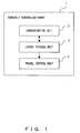
- FIG. 1shows the basic configuration of the remotely controlled robot of the present invention.
- a robot 1comprises a layout storage unit 2, a communication unit 3 and a travel control unit 4.
- the layout storage unit 2stores the layout plan of a building, such as a house, and the communication unit 3 receives a position in the layout plan that is remotely designated from a remote terminal, for example, through a network.
- the travel control unit 4controls the travel of the robot 1 to the designated position.
- the remotely controlled robotcan comprise a step getting over unit getting over a step c in a building, based on the result of step detection by an obstacle detecting sensor.
- the robotcan further comprise a self-position identification unit identifying the current position and direction of the robot in a building, and the travel control unit 4 can control the travel of the robot 1, based on the result of the identification.
- the communication unit 3 shown in Fig. 1can also receive the designation of a room in the layout plan of a building from a remote terminal.
- the travel control unit 4controls the travel of the robot 1 to, for example, the entrance of the designated room.
- the remotely controlled robotcan further comprise a picture taking unit taking a picture in a building and a communication unit transmitting a picture taken by the picture taking unit when a robot regularly or irregularly patrols inside the building, to a computer with a memory device that can be accessed from the outside through a network, such as a Web server connected to the internet.
- a robotcan incorporate such a computer, such as a Web server.
- the preferred embodimentcan further comprise a revolution unit changing the shooting direction of the picture taking unit, and an infrared emission/reception unit emitting/receiving an infrared ray for operating equipment, such as electrical home appliances that are in parallel to the shooting direction of the picture taking unit.
- a revolution unit changing the shooting direction of the picture taking unitand an infrared emission/reception unit emitting/receiving an infrared ray for operating equipment, such as electrical home appliances that are in parallel to the shooting direction of the picture taking unit.
- an infrared emission/reception unitemitting/receiving an infrared ray for operating equipment, such as electrical home appliances that are in parallel to the shooting direction of the picture taking unit.
- itcan further comprise the step getting over unit described earlier.
- the communication unitcan also start the computer described earlier, such as a Web server.
- the remotely controlled robot of the present inventioncomprises a script storage unit storing the script programs of one or more operations of a robot, and a communication unit receiving a command to execute one of the stored programs from the outside.
- the remotely controlled robot of the present inventionfurther comprises a command receiving unit receiving an emergency notice/command which is sent to the outside from a person within a building, such as a resident of a house, and a communication unit issuing an urgent notice to a predetermined external terminal according to the command.
- the robotcan further comprise the picture taking unit taking the inside pictures of a building, the revolution unit changing the shooting direction of the picture taking unit and the communication unit transmitting pictures taken by the picture taking unit, to the outside, according to the command from the outside.
- the robot self-position identification method of the present inventioncan be implemented by a robot with a camera whose shooting direction can be changed.
- the robottakes in advance the panoramic picture of each room where the robot may travel, generates a reference picture by extracting a plurality of block pictures from the panoramic picture and identifies a room where the robot is located, by applying correlation calculation and DP matching in the panoramic picture taken in a position where the robot is located, using a picture of the same size as the block picture and the reference picture.
- the position of a landmarkcan also be calculated in an picture taken in the position where the robot is located, using a landmark picture taken in advance in the room as a reference template, the distance between the robot and the landmark can also be stereoscopically measured and the self-position and direction of the robot in the identified room can also be identified.
- a vertical line in a taken landmark picturecan also be extracted and the position and direction of a robot can also be exactly identified by using two angles that are formed by one of the shooting directions of two cameras and the direction of the vertical line.
- the travel destination or target room of a robotcan be remotely designated in the layout plan of a building.
- a room where the robot is locatedcan be identified.
- Fig. 2shows the configuration of the remotely controlled robot in the preferred embodiment.
- the robotcomprises a control computer 10, a travel mechanism 11, a camera 12 taking pictures around the robot, a pan/tilt stand 13 for adjusting the horizontal revolution angle and elevation/ depression angle of the camera, an infrared transmitter/receiver 14 that is, for example, mounted on the same base as that of the camera, transmitting infrared rays in parallel to the shooting direction of the camera and receiving infrared rays to get remote control data, a radio communication unit 15, an input device 16, a pointing device 17, a display device 18, a variety of switches 19 and a variety of sensors 20.
- the camera 12is, for example, a video camera.
- the infrared transmitter/receiver 14is installed in the vicinity of the camera 12, and can transmit infrared rays in the same direction as the shooting direction. Its base can be revolved in an arbitrary direction by the pan/tilt stand 13 used as a camera revolution mechanism.
- the transmitter/receiver 14can transmit infrared rays in order to operate a specific electrical home appliance located in that direction while viewing the picture of the camera 12.
- the radio communication unit 15conducts communications in order to enable a portable data terminal, such as a cellular phone, a PDA (personal digital assistant) etc., or a personal computer to execute such a remote control.
- a portable data terminalsuch as a cellular phone, a PDA (personal digital assistant) etc.
- a personal computerto execute such a remote control.
- Fig. 3shows how to remotely operate the robot.
- the robotcan be remotely controlled, for example, through the Internet, and a Web server is provided for the robot for that purpose.
- the robot control computer 10 shown in Fig. 2comprises a Web server 21, a control execution unit 22 executing control and an interface 23, such as CGI (common gateway interface) , ISAPI (Internet server application programming interface) or the like, which is located between the Web server 21 and the control execution unit 22.
- the Web server 21can be remotely accessed through a Web browser 24 and the Internet 25.
- the Web browser 24can be connected to the Internet 25 by menu selection.
- the CGI/ISAPI 23is called according to a command from the Web browser 24.
- the command formatis converted into a format suited to control the robot.
- the control execution unit 22executes the command.
- control computer 10From the control computer 10, status and picture data that are returned from the control execution unit 22 are transmitted to the CGI/ISAPI 23, and its data format is converted. Then, the Web server 21 provides the Web browser 24 with the status and picture data as an html file through the Internet 25. Then, the Web browser 24 displays the menu and picture.
- Fig. 4shows the external appearances of the remotely controlled robot.
- the left and right side picturesshow its front and back external appearances, respectively.
- a stereo camera 31corresponding to the camera shown in Fig. 2
- an electrical appliance remote control transmitter 32corresponding to the infrared transmitter/receiver 14
- a power switch 33corresponding to the variety of switches 19
- a menu switch 34corresponding to the variety of switches 19
- a bumper switch 35used as an obstacle search sensor
- an emergency button 36used for a resident of a building to issue an emergency notice to the outside, which is described later, are provided.
- a travel unit 37 corresponding to the travel mechanism 11, a monitor 38 corresponding to the display device 18, a near distance sensor 39 corresponding to the variety of sensors 20, a microphone, a speaker 41 and a track pointer 42are also provided on the front.
- a pan/tilt unit 43 corresponding to the pan/tilt stand 13 shown in Fig. 2is provided.
- Fig. 5shows the inside of the robot.
- a USB cameracorresponding to the stereo camera 31 shown in Fig. 4
- a distance measuring sensorcorresponding to the near distance sensor 39 and an LCD corresponding to the monitor 38 are shown.
- a mechanism by which the robot can get over clear obstacles and steps using two (left and right) crawlers (wheels) and one or more freely-revolving ball castors (auxiliary wheels)is used.
- crawlerscan revolve on a plane perpendicular to the center of the revolution axis of each wheel, and when the robot revolves at one point, they operate as if they were two (left and right) wheels rather than crawlers.
- the auxiliary wheeltouches on the ground at one point, the grounding point is stable and the one-point revolution center of the entire robot is stable, the robot can get over an obstacle, which is higher than the structural base of the robot.
- another publicly known technologycan also be used.
- Fig. 6shows the configuration of the remotely controlled robot.
- a main CPU 53 on a CPU substrate 51 and an MPU controller 65 on an extension substrate 52correspond to the control computer 10 shown in Fig. 2.
- the Web server 21 inside the control computer 10 shown in Fig. 3can be configured, for example, using the main CPU 53 as a center device.
- the Web servercan be provided separately from the robot, which is described later. In that case, a server computer is provided separately between the robot and the Internet.
- a pointing device 54In Fig. 6, a pointing device 54, a USB (universal serial bus) port for user extension 55, a voice codec 58 with a microphone 56 and a speaker 57 connected, an LCD interface 60 with an LCD 59 connected, CF (compact flash) memory 61 connected through a control unit and a communication module 62 connected through a control unit, are connected to the main CPU 53.
- a USBuniversal serial bus
- a CMOS camera 66controlling the rotation of the pan/tilt stand 13 shown in Fig. 2, three motors 68 rotating the crawlers and ball castors that are shown in Fig. 5 as the travel mechanism 11, a switch sub-substrate 69 with LEDs and buttons mounted, a distance sensor 70, a potentiometer for pan (horizontal rotation angle) 71, a potentiometer for tilt (elevation angle) 72, an infrared ray transmitter 73, an infrared ray receiver 74 and a DC/DC charging circuit 77 with an AC adaptor 75 and a battery 76 connected, are connected to both the MPU controller 65 and HUB 64.
- Fig. 7is a flowchart showing the process of a robot receiving the designation of a target destination from a remote place, according to a layout plan.
- the process of a robot traveling to its destinationis performed by a robot storing in advance the layout plan of a building in its memory, the robot transmitting a picture of the layout plan to the remote terminal of a client, and a client designating its travel destination for the robot, according to the layout plan.
- step S1the robot identifies its own position. This self-position identification is described later. Then, in step S2, the robot receives a picture size data size that can be displayed on a mobile terminal, from the remotely located client.
- step S3the size of the layout picture stored in the memory is converted into that of the data received from the client using the data and stores the conversion scale.
- step S4the robot transmits the layout picture containing the self-position information identified in step S1, to the client.
- step S5the robot receives the coordinates of the destination designated from the client.
- step S6the robot calculates the destination coordinates on a real scale from both the conversion scale information stored in step S3 and the coordinates of the destination designated by the client.
- step S7the robot produces a route to the destination.
- step S8the robot travels towards the destination.
- step S9the robot determines whether it arrives at the destination. The robot repeats the processes in steps 8 onward until it arrives at the destination. If it determines that it arrives at the destination, the process terminates.
- Fig. 8shows a display example of a layout plan in a remote terminal, such as a remotely located client' s cellular phone, etc., in the process of Fig. 7.
- a layout planis outputted on a display screen.
- the current position and direction of a robotare indicated there by a triangle mark in a bedroom.
- the destination of the robot, designated by a clientis indicated by a cursor in a living room.
- Fig. 9is a flowchart showing the process of a robot, in which a client designates the name or number of a target room, instead of a travel destination. Only the differences in a flowchart between Figs. 9 and 7 are described below.
- step S3the robot transmits a layout picture containing self-position information, to the client.
- step S10the robot receives the data of the name or number of a target room from the client.
- step S11the robot calculates the coordinates of a travel destination from the name or number of a target room, using a correspondence table storing in advance the coordinates of a target, such as an entrance, for each room. Then, the robot performs the same processes in step S7 through S9 as those shown in Fig. 7.
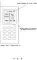
- Fig. 10shows an example of the display screen of a client terminal, in the process shown in Fig. 9.
- a menu indicating both a layout plan and a travel destinationis outputted on the display screen.
- the clientdesignating a specific room in the menu, the robot travels to the room.
- a layout planis outputted on the display screen, there is not necessarily a need to display a layout plan.
- the process loadcan be reduced and accordingly, process speed can be improved.
- a robotidentifies both a room where the robot is located and its exact position by picture taking and registering in advance the panoramic picture of each room in a building and comparing the panoramic picture of each room with a panoramic picture taken by the robot in a room where the robot currently is located.
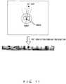
- Fig. 11shows how to take a panoramic picture of a room in order to register in advance the panoramic picture of each room in a building.
- a 360° panoramic picturecan be produced for preparation by locating a robot, for example, at the center of a room, turning a camera, for example, in steps of 30 degrees, taking pictures, and combining them, for example, reducing their sizes.
- a robotfor example, at the center of a room
- turning a camerafor example, in steps of 30 degrees
- taking picturesfor example, reducing their sizes.
- matching between the picture taken when identifying the self-position and the currently taken picturemay degrade if the currently taken picture is compressed in order to shorten a process time, such as a calculation time, etc., or if it is too clear. Therefore, the level of the currently taken picture is averaged.
- Fig. 12is a flowchart showing the process of identifying a room where the robot is located.
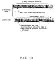
- Fig. 13shows the picture correlation calculation conducted in the identification process. Firstly, in steps S20 through S22 of Fig. 12, a panoramic picture is taken for preparation, which has been described in Fig. 11, and a reference template that is used in actual position identification is generated.
- step S20the panoramic picture of each room located at an area to which a robot may travel, is taken.
- step S21the size of the panoramic picture is reduced and its level is averaged.
- step S22a plurality of small block pictures are extracted from the panoramic picture at equal pitches, that is, horizontally at equal intervals, the pictures are enlarged or reduced, and a reference template is generated.
- the upper picture of Fig. 13shows examples of pictures extracted as small blocks in this way.
- k small block picturesare extracted from the panoramic picture of each room for each of the registered pictures of n rooms.
- Processes in steps S23 and after of Fig. 12show the identification process of a room where the robot currently is located. Firstly, in step S23, the panoramic picture of a room where the robot currently is located is taken. In step S24, the size of the panoramic picture is reduced and its level is averaged. In steps S25 and after, the currently taken picture is compared with the reference template.
- the lower picture of Fig. 13shows examples of the extracted pictures of a room where the robot currently is located.
- the panoramic picture of a room where the robot currently is locatedis compared with each of the registered pictures of n rooms, using an extraction start position and xrange small block pictures as a search reference position and a search range, respectively.
- step S25 of Fig. 12it is determined whether such a process has been applied to all the registered rooms. If such a process has not been applied to all the registered rooms, in step S26, it is determined whether all reference block numbers, specifically, k extracted pictures registered for each of the n rooms shown in Fig. 13 have been searched for.
- step S27it is determined whether all search range numbers, specifically, the entire search range of xrange pixels from the search reference position in the panoramic picture of a room where the robot currently is located shown in Fig. 13 has been searched for. If the entire search range of xrange pixels from the search reference position in the panoramic picture of a room has not been searched for, in step S28 it is determined whether all enlargement/reduction numbers, specifically, the number of pictures compared with the currently taken room picture of n pictures that are obtained by enlarging and reducing the small block pictures extracted in step S22, reaches n.
- step S29the correlation calculation between the reference template, specifically, the correlation between the reference template with the process target enlargement/reduction number of the process target small-blocked picture of the process target room and the panoramic picture of the current room designated by the search range number is calculated. Then, in step S30, the enlargement/reduction number is incremented, and the processes in steps S28 onward are repeated.
- step S28it is determined that the enlargement/reduction number is more than n, that is, n pictures with an enlargement/reduction number have been all processed
- step S31a picture with an enlargement/reduction number whose result of the correlation calculation is the smallest of all pictures with a search range number in process is designated as the result of the search in the search position.
- step S32the search range number is incremented, and then the processes in steps S27 onward are repeated.
- step S27it is determined that the search range number is more than xrange, it means that the comparison of a picture with a reference block number in process is completed. Therefore, in step S33, the reference block number is incremented and then the processes in steps S26 onward are repeated.
- step S26If in step S26 it is determined that the reference block number is more than k, it means that the comparison of a room in process is completed. Therefore, in step S34, a two-dimensional matrix that is determined by both k small block pictures obtained by conducting the correlation calculation of the room and search range xrange is generated. In step S35, cost is calculated, for example, by applying dynamic programming (DP) matching, using the result of the correlation calculation and distance as parameters, and the lowest cost of a room in process is calculated.
- DPdynamic programming
- Each element of the two-dimensional matrix whose respective number of rows and columns are determined by the k small block pictures and search range xrangebecomes the data of a reference template whose correlation calculation value between the current panoramic picture and a picture in each search position is the lowest of the respective n templates obtained by enlarging/reducing the k small blocks shown in Fig.13.
- Step S35the lowest cost of a room in process can be calculated by applying general DP matching that calculates cost using the result of correlation calculation and distance as parameters.
- step S36the room number is incremented, and the processes in and after step S25 are repeated. If it is determined that in step S25 all the rooms are processed, in step S37 a room with the lowest cost of the costs calculated for each room in step S35 is determined to be the room where the robot currently is located, and the process terminates.
- Figs. 14 and 15are flowcharts showing the process of identifying the position of a robot in a room after a room where the robot is located in the process of Fig. 12 has been identified.
- Figs. 14 and 15are flowcharts showing the processes identifying rough and exact positions of a robot, respectively.
- step S40 of Fig. 14firstly, prior to the identification of the real position of a robot, a landmark, such as a pillar, is selected in the panoramic picture taken and registered, as described in Fig. 11, and both its position in the picture and its position in the real room are registered. Then, in step S41, the picture of the pillar is extracted from the panoramic picture and an enlargement/reduction template is generated.
- a landmarksuch as a pillar
- step S42correlation calculation is applied using the enlargement/reduction template of the pillar in a room where the robot currently is located, that is, the same room as identified in the process of Fig. 12, and the position of the pillar in the current panoramic picture is specified.
- step S43a distance between the robot and the specified pillar is stereoscopically measured, and the rough position of the robot is identified.
- Fig. 16shows the position of a robot, calculated in this way.
- step S43for example, distances from the four corners of a room are calculated, and the intersecting points of the circular arcs of circulars each with each of the distances as a diameter is obtained as the result of the rough position identification of a robot located inside a rectangle.
- Fig. 15is a flowchart showing the process of identifying the exact position of a robot, based on the rough position calculated in Fig. 14.
- step S45 of Fig. 15in order to extract a vertical line from the picture of the pillar, (1) the edge of the picture is extracted, (2) the extracted picture is digitized and (3) a histogram vertically projected is calculated.
- a histogram vertically projectedmeans to determine an edge with the maximum value as the edge of the pillar, since the histogram value of a low edge, such as a desk, of the vertically detected edges becomes small.
- the edge of the pillaris extracted.
- step S46respective angles formed by the extracted vertical line, that is, the edge of the pillar, and each of the shooting directions of two cameras are calculated.
- step S47in order to calculate the exact position and direction of the robot in the room, virtual points are set in a matrix shape in the room, and two angles formed by the vertical line of the pillar corresponding to the position/posture of the robot and each of the shooting directions of the two cameras are calculated using the direction of the robot at each point as a parameter, and a value corresponding to the difference the angles calculated in steps S46 and S47 is calculated as cost.
- step S48a position and a direction where the cost is the minimum are calculated as the exact position and direction of the robot. Then, the process terminates.
- a triangle in the rectangle shown in Fig. 16indicates the exact current position and direction of the robot that are identified by the process shown in Fig. 15.
- the data for the position and direction of a robot that are identifiedthus is notified to the client, for example, by the radio communication unit 15 shown in Fig. 2, as requested.
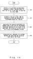
- FIG. 17is a flowchart showing the remote emergency notice process of a remotely controlled robot.
- a robotis provided with an emergency button. For example, if the resident of a building wants to notify a remote place of emergency, he/she can do so by pushing the emergency button.
- step S50 of Fig. 17the emergency button is monitored, and in step S51 it is determined whether the emergency button is pushed. If the button is not pushed, the processes in and after step S50 are repeated. If the button is pushed, in step S52 emergency is notified to an address registered in advance over electronic mail or telephone. Then, the process terminates.
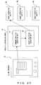
- a method for remotely checking the picture of, for example, a room in a building, that is taken by a robotis described with reference to Figs. 18 and 19.
- Fig. 18for example, if a robot 80 regularly patrols inside the building and transmits the picture of each room, which it takes, to a server computer 81 provided with a Web server through a wireless LAN, the picture can be remotely referenced by accessing this Web server.
- the server computer 81comprises a socket server 82 receiving picture data transmitted from the robot 80, and a Web server 83.
- the picture transmitted from the robot 80is stored in a folder on the Web server 83 that can be referenced from the outside.
- the Web browser 24issues a picture obtain command to the Web server 83 through the Internet 25, and displays the picture transmitted from the Web server 83 through the Internet 25.
- the communication module 62such as a LAN card, etc., is inserted in a connector.
- a robot control computer 10comprises a Web server 21, and the Web browser 24 can refer to the picture by accessing the Web server 21 through the Internet 25.
- the communication module 62such as a PHS card, etc., is inserted in a connector.
- the Web servercan start and allow it to be accessed from the outside.
- a method for remotely designating a script stored in a robot and making the robot perform an operation that is programmed in advanceis described with reference to Fig. 20.
- the command analysis/execution unit 87 of a remotely controlled robot 86analyzes the command. If the command designates the selection of a script and its execution, a script selection/execution unit 88 selects one of a plurality of robot operation scripts 89 1 through 89 n stored in the robot and performs the operation.
- a remotely controlled robotcan be made to travel to a target destination by designating the destination, for example, in a layout plan displayed on a remote terminal.
- a remote terminalcan also check the inside picture of a building.
- the remote terminalcan make a robot perform an operation that is programmed in advance.
- the resident of a buildingcan issue an emergency notice to a remote location.
- the present inventionaims to provide functions to operate electrical home appliances through the Internet and to remotely monitor the state of a client's home while he/she is away, and the exact self-position identification method of a robot.
- the present inventioncan be used in all industries using a remotely controlled robot and in an industry needing to identify an exact self-position of a robot.
- the present inventioncan be used in a variety of industries, such as electrical home appliance industries, building management industries, etc.
Landscapes
- Engineering & Computer Science (AREA)
- Physics & Mathematics (AREA)
- General Physics & Mathematics (AREA)
- Radar, Positioning & Navigation (AREA)
- Remote Sensing (AREA)
- Aviation & Aerospace Engineering (AREA)
- Automation & Control Theory (AREA)
- Computer Vision & Pattern Recognition (AREA)
- Theoretical Computer Science (AREA)
- Multimedia (AREA)
- Electromagnetism (AREA)
- Manipulator (AREA)
- Control Of Position, Course, Altitude, Or Attitude Of Moving Bodies (AREA)
Abstract
Description
Claims (16)
- A robot that can be remotely controlled,comprising:layout storage means for storing a layout plan ofa building;communication means for receiving designation ofa position designated in the layout plan from a remoteterminal; andtravel control means for controlling travel of arobot to the designated position.
- The remotely controlled robot according to claim1, further comprising
step getting over means for getting over steps ina building, based on the result of step detection byan obstacle detecting sensor. - The remotely controlled robot according to claim1, further comprising
self-position identification means foridentifying the current position and direction of therobot in the building, wherein
said travel control means controls the travel ofthe robot to the designated position, based on the result of the identification. - A robot that can be remotely controlled,comprising:layout storage means for storing a layout plan ofa building;communication means for receiving designation ofa room designated in the layout plan from a remoteterminal; andtravel control means for controlling the travelof a robot to the designated room.
- A robot that can be remotely controlled,comprising:picture taking means for taking an inside pictureof a building;communication means for transmitting the picturetaken by the picture taking means when the robotregularly/irregularly patrols inside a building, to acomputer with memory accessible from the outside througha network.
- The remotely controlled robot according to claim5, further comprising
step getting over means for getting over steps in a building, based on the result of step detectionby an obstacle detecting sensor. - The remotely controlled robot according to claim5, further comprising
rotation means for changing the shootingdirection of the picture taking means; and
infrared ray emission/reception means foremitting/receiving an infrared ray in parallel to theshooting direction of the picture taking means. - The remotely controlled robot according to claim5, wherein
the computer to which said communication meanstransmits the picture is a Web server connected to theInternet. - A robot that can be remotely controlled,comprising:picture taking means for taking an inside pictureof a building;communication means for transmitting the picturetaken by the picture taking means when the robotregularly/irregularly patrols inside a building, to acomputer with memory accessible from the outside through a network.
- The remotely controlled robot, according to claim9, further comprising:communication means for starting the computerwhen a ringer signal is transmitted from the outsidethrough the Internet a prescribed number of times.
- A robot that can be remotely controlled,comprising:script storage means for storing the programs ofscripts for one or more operations stored in the scriptstorage unit; andcommunication means for receiving the command toexecute one of the programs stored in the script storagemeans.
- A robot that can be remotely controlled,comprising:command receiving means for receiving anemergency command from a person in a building; andcommunication means for issuing the emergencycommand to a predetermined remote terminal accordingto the command.
- The robot that can be remotely controlledaccording to claim 12, further comprising:picture taking means for taking an inside pictureof a building;rotation means for changing the shootingdirection of the picture taking means; andcommunication means for transmitting a picturetaken by the picture taking means to the outside,according to the command on a shooting direction fromthe outside.
- A self-position identification method of a robotwith a camera whose shooting direction can be changed,comprising of:taking in advance a panoramic picture of each roomto which the robot may travel;generating a reference picture by extracting aplurality of block pictures from the panoramic picture;andidentifying a room where the robot is located, byapplying correlation calculation and DP matching, usingboth a picture of the same size as the block picturein the panoramic picture taken in a position where therobot is located, and the reference picture.
- The robot self-position identification methodaccording to claim 14, wherein
designating the picture of a landmark, taken inadvance, of all the landmarks in the identified room,as a reference template, applying correlationcalculation between the reference template and a picturetaken in a position where the robot is located, andcalculating the position of the landmark in the takenpicture; and
stereoscopically measuring a distance betweenthe robot and each of a plurality of landmarks andidentifying the own robot's position and direction inthe identified room. - The robot self-position identification methodaccording to claim 15, wherein
extracting a vertical line in the taken pictureof the landmark;
calculating cost corresponding to a differencebetween an angle that is formed by each of two shootingdirections of two cameras and the direction of thevertical line, and a resulted angle of calculation thatis formed by each of the two shooting directions of thetwo cameras and the direction of the landmark presumingthe position and direction of the robot; and
changing the presumed position and direction ofthe robot and identifying a presumed position anddirection of the robot, where the cost becomes the lowest,to be the position and direction of the robot.
Applications Claiming Priority (1)
| Application Number | Priority Date | Filing Date | Title |
|---|---|---|---|
| PCT/JP2002/005370WO2003102706A1 (en) | 2002-05-31 | 2002-05-31 | Remotely-operated robot, and robot self position identifying method |
Publications (3)
| Publication Number | Publication Date |
|---|---|
| EP1510896A1true EP1510896A1 (en) | 2005-03-02 |
| EP1510896A4 EP1510896A4 (en) | 2005-12-14 |
| EP1510896B1 EP1510896B1 (en) | 2016-03-09 |
Family
ID=29606642
Family Applications (1)
| Application Number | Title | Priority Date | Filing Date |
|---|---|---|---|
| EP02730841.0AExpired - LifetimeEP1510896B1 (en) | 2002-05-31 | 2002-05-31 | Remotely-operated robot, and robot self position identifying method |
Country Status (7)
| Country | Link |
|---|---|
| US (1) | US7120519B2 (en) |
| EP (1) | EP1510896B1 (en) |
| JP (1) | JP4448024B2 (en) |
| KR (1) | KR100812506B1 (en) |
| CN (1) | CN100451897C (en) |
| AU (1) | AU2002304133A1 (en) |
| WO (1) | WO2003102706A1 (en) |
Cited By (18)
| Publication number | Priority date | Publication date | Assignee | Title |
|---|---|---|---|---|
| EP1548532A4 (en)* | 2002-10-01 | 2007-08-08 | Fujitsu Ltd | ROBOT |
| WO2009089369A1 (en)* | 2008-01-08 | 2009-07-16 | Raytheon Sarcos, Llc | Point and go navigation system and method |
| US7845440B2 (en) | 2006-11-13 | 2010-12-07 | Raytheon Sarcos, Llc | Serpentine robotic crawler |
| US8002365B2 (en) | 2006-11-13 | 2011-08-23 | Raytheon Company | Conformable track assembly for a robotic crawler |
| US8042630B2 (en) | 2006-11-13 | 2011-10-25 | Raytheon Company | Serpentine robotic crawler |
| US8185241B2 (en) | 2006-11-13 | 2012-05-22 | Raytheon Company | Tracked robotic crawler having a moveable arm |
| US8317555B2 (en) | 2009-06-11 | 2012-11-27 | Raytheon Company | Amphibious robotic crawler |
| US8392036B2 (en) | 2009-01-08 | 2013-03-05 | Raytheon Company | Point and go navigation system and method |
| US8393422B1 (en) | 2012-05-25 | 2013-03-12 | Raytheon Company | Serpentine robotic crawler |
| US8434208B2 (en) | 2007-05-07 | 2013-05-07 | Raytheon Company | Two-dimensional layout for use in a complex structure |
| US8571711B2 (en) | 2007-07-10 | 2013-10-29 | Raytheon Company | Modular robotic crawler |
| US9031698B2 (en) | 2012-10-31 | 2015-05-12 | Sarcos Lc | Serpentine robotic crawler |
| EP3217373A4 (en)* | 2014-12-11 | 2018-02-14 | Huawei Technologies Co., Ltd. | Terminal with infrared remote control function and infrared remote control pairing method |
| EP3343308A1 (en)* | 2016-12-20 | 2018-07-04 | Miele & Cie. KG | A floor care device and method and device for detecting a room using a floor care device |
| JP2018205865A (en)* | 2017-05-31 | 2018-12-27 | ヴイストン株式会社 | Information communication device and server device |
| US11687092B2 (en) | 2018-04-23 | 2023-06-27 | Sharkninja Operating Llc | Techniques for bounding cleaning operations of a robotic surface cleaning device within a region of interest |
| US12311550B2 (en) | 2020-12-31 | 2025-05-27 | Sarcos Corp. | Smart control system for a robotic device |
| US12376722B2 (en) | 2021-08-13 | 2025-08-05 | Sharkninja Operating Llc | Robotic cleaner |
Families Citing this family (77)
| Publication number | Priority date | Publication date | Assignee | Title |
|---|---|---|---|---|
| US7330776B1 (en)* | 2000-10-06 | 2008-02-12 | Innovation First, Inc. | System, apparatus, and method for managing and controlling robot competitions |
| DE10150423A1 (en)* | 2001-10-11 | 2003-04-30 | Siemens Ag | Method and arrangement as well as computer program with program code means and computer program product for assigning a partial area of a total area divided into several partial areas to one of several mobile units |
| US7756322B2 (en)* | 2003-08-18 | 2010-07-13 | Honda Motor Co., Ltd. | Picture taking mobile robot |
| KR100543709B1 (en)* | 2003-12-23 | 2006-01-20 | 삼성전자주식회사 | Method of using rotational movement amount of moving object and computer readable recording medium storing device and computer program |
| EP1741044B1 (en)* | 2004-03-27 | 2011-09-14 | Harvey Koselka | Autonomous personal service robot |
| JP2006074207A (en)* | 2004-08-31 | 2006-03-16 | Toshiba Corp | Mobile information device, moving method, information system, and position estimating method |
| KR20060059006A (en)* | 2004-11-26 | 2006-06-01 | 삼성전자주식회사 | METHOD AND APPARATUS FOR MOBILE APPLIANCES TO MOVE ACCIDENTS WITH HIDENTS |
| US7436143B2 (en)* | 2005-04-25 | 2008-10-14 | M-Bots, Inc. | Miniature surveillance robot |
| JP4824362B2 (en)* | 2005-08-01 | 2011-11-30 | 本田技研工業株式会社 | Mobile robot controller |
| EP2050544B1 (en)* | 2005-09-30 | 2011-08-31 | iRobot Corporation | Robot system with wireless communication by TCP/IP transmissions |
| DE112006003363B4 (en)* | 2005-12-16 | 2016-05-04 | Ihi Corporation | Method and apparatus for identifying the self-position, and method and apparatus for measuring a three-dimensional shape |
| DE112006003361T5 (en)* | 2005-12-16 | 2008-10-16 | Ihi Corporation | Method and apparatus for recording / displaying three-dimensional shape data and method and apparatus for measuring a three-dimensional shape |
| DE112006003380T5 (en)* | 2005-12-16 | 2008-10-16 | Ihi Corporation | Method and apparatus for the positional matching of three-dimensional shape data |
| US8884763B2 (en)* | 2006-10-02 | 2014-11-11 | iRobert Corporation | Threat detection sensor suite |
| KR100857603B1 (en)* | 2007-03-29 | 2008-09-09 | 삼성전자주식회사 | Electronic component inspection system and control method |
| WO2008152733A1 (en)* | 2007-06-15 | 2008-12-18 | Fujitsu Limited | Robot |
| JP2009011362A (en)* | 2007-06-29 | 2009-01-22 | Sony Computer Entertainment Inc | Information processing system, robot apparatus, and its control method |
| KR101469246B1 (en)* | 2007-08-07 | 2014-12-12 | 삼성전자주식회사 | Apparatus and method for taking pictures in a robot |
| CN101456183A (en)* | 2007-12-14 | 2009-06-17 | 鸿富锦精密工业(深圳)有限公司 | Robot and wireless communication device controlling the robot |
| JP5201411B2 (en)* | 2008-11-21 | 2013-06-05 | 株式会社Ihi | Bulk picking device and control method thereof |
| WO2010144813A1 (en) | 2009-06-11 | 2010-12-16 | Raytheon Sarcos, Llc | Method and system for deploying a surveillance network |
| TWI409717B (en)* | 2009-06-22 | 2013-09-21 | Chunghwa Picture Tubes Ltd | Image transformation mtehod adapted to computer programming product and image display device |
| JP5542521B2 (en)* | 2010-05-13 | 2014-07-09 | 株式会社日立製作所 | Freely installable network camera device |
| CN102960037B (en)* | 2010-05-19 | 2016-08-10 | 诺基亚技术有限公司 | Physically Constrained Radio Maps |
| US9014848B2 (en) | 2010-05-20 | 2015-04-21 | Irobot Corporation | Mobile robot system |
| US8918209B2 (en) | 2010-05-20 | 2014-12-23 | Irobot Corporation | Mobile human interface robot |
| US8935005B2 (en) | 2010-05-20 | 2015-01-13 | Irobot Corporation | Operating a mobile robot |
| US8918213B2 (en) | 2010-05-20 | 2014-12-23 | Irobot Corporation | Mobile human interface robot |
| US9906838B2 (en) | 2010-07-12 | 2018-02-27 | Time Warner Cable Enterprises Llc | Apparatus and methods for content delivery and message exchange across multiple content delivery networks |
| US9007432B2 (en) | 2010-12-16 | 2015-04-14 | The Massachusetts Institute Of Technology | Imaging systems and methods for immersive surveillance |
| US9036001B2 (en) | 2010-12-16 | 2015-05-19 | Massachusetts Institute Of Technology | Imaging system for immersive surveillance |
| US8930019B2 (en) | 2010-12-30 | 2015-01-06 | Irobot Corporation | Mobile human interface robot |
| KR101855831B1 (en) | 2011-05-12 | 2018-05-09 | 엘지전자 주식회사 | Cleaning apparatus and collaboration cleaning method using robot cleaners |
| JP5707238B2 (en)* | 2011-06-02 | 2015-04-22 | 株式会社日立製作所 | Image search apparatus and image search system |
| US8919476B2 (en) | 2011-07-11 | 2014-12-30 | Holland Moving & Rigging Supplies, Inc. | Platform dolly system |
| US8958911B2 (en) | 2012-02-29 | 2015-02-17 | Irobot Corporation | Mobile robot |
| JP2013242738A (en)* | 2012-05-22 | 2013-12-05 | Sharp Corp | Robot device, terminal device, remote control system for robot device and program |
| JP6052576B2 (en)* | 2012-05-30 | 2016-12-27 | 日本電気株式会社 | Information processing system, information processing method, information processing apparatus, portable terminal, and control method and control program thereof |
| JP5898022B2 (en)* | 2012-09-18 | 2016-04-06 | シャープ株式会社 | Self-propelled equipment |
| CN103903219A (en)* | 2012-12-26 | 2014-07-02 | 联想(北京)有限公司 | Information processing method and system |
| US20140249695A1 (en)* | 2013-03-01 | 2014-09-04 | Robotex Inc. | Low latency data link system and method |
| CN104183168B (en)* | 2013-05-28 | 2018-04-27 | 中建八局第一建设有限公司 | Construction 4D distant test systems |
| US9409292B2 (en) | 2013-09-13 | 2016-08-09 | Sarcos Lc | Serpentine robotic crawler for performing dexterous operations |
| US9566711B2 (en) | 2014-03-04 | 2017-02-14 | Sarcos Lc | Coordinated robotic control |
| US20150283703A1 (en)* | 2014-04-03 | 2015-10-08 | Brain Corporation | Apparatus and methods for remotely controlling robotic devices |
| EP2933604B1 (en)* | 2014-04-14 | 2016-11-30 | Softbank Robotics Europe | A method for localizing a robot in a localization plane |
| US9860077B2 (en) | 2014-09-17 | 2018-01-02 | Brain Corporation | Home animation apparatus and methods |
| US9849588B2 (en) | 2014-09-17 | 2017-12-26 | Brain Corporation | Apparatus and methods for remotely controlling robotic devices |
| US9821470B2 (en) | 2014-09-17 | 2017-11-21 | Brain Corporation | Apparatus and methods for context determination using real time sensor data |
| US10102226B1 (en)* | 2015-06-08 | 2018-10-16 | Jasmin Cosic | Optical devices and apparatuses for capturing, structuring, and using interlinked multi-directional still pictures and/or multi-directional motion pictures |
| US10071303B2 (en) | 2015-08-26 | 2018-09-11 | Malibu Innovations, LLC | Mobilized cooler device with fork hanger assembly |
| EP3356090B1 (en)* | 2015-09-29 | 2020-12-23 | Koninklijke Philips N.V. | Automatic robotic arm calibration to camera system using a laser |
| JP6671507B2 (en)* | 2016-01-04 | 2020-03-25 | 浙江立▲ビアオ▼机器人有限公司Zhejiang Libiao Robots Co., Ltd. | Method and Apparatus for Returning to Robot Site {METHOD AND DEVICE FOR RETURNING ROBOTS FROM SITE} |
| US10471611B2 (en)* | 2016-01-15 | 2019-11-12 | Irobot Corporation | Autonomous monitoring robot systems |
| CN105446162B (en)* | 2016-01-26 | 2018-11-20 | 北京进化者机器人科技有限公司 | A kind of intelligent home furnishing control method of smart home system and robot |
| JP6864433B2 (en)* | 2016-01-29 | 2021-04-28 | 東芝ライフスタイル株式会社 | Vacuum cleaner |
| CN105867433A (en)* | 2016-03-31 | 2016-08-17 | 纳恩博(北京)科技有限公司 | Moving control method, moving electronic device and moving control system |
| US10807659B2 (en) | 2016-05-27 | 2020-10-20 | Joseph L. Pikulski | Motorized platforms |
| CN106094816A (en)* | 2016-05-31 | 2016-11-09 | 芜湖智久机器人有限公司 | A kind of BS control system of AGV |
| CN106155059A (en)* | 2016-08-16 | 2016-11-23 | 邹霞 | The Intelligent unattended control loop of view-based access control model |
| CN106774315B (en)* | 2016-12-12 | 2020-12-01 | 深圳市智美达科技股份有限公司 | Autonomous navigation method and device for robot |
| KR101976424B1 (en)* | 2017-01-25 | 2019-05-09 | 엘지전자 주식회사 | Moving Robot |
| JP6809267B2 (en)* | 2017-02-10 | 2021-01-06 | 富士ゼロックス株式会社 | Information processing equipment, information processing systems and programs |
| JP2018185182A (en)* | 2017-04-25 | 2018-11-22 | 東京電力ホールディングス株式会社 | Positioning device |
| US10100968B1 (en) | 2017-06-12 | 2018-10-16 | Irobot Corporation | Mast systems for autonomous mobile robots |
| CN107314773B (en)* | 2017-08-18 | 2019-10-01 | 广东宝乐机器人股份有限公司 | The map creating method of mobile robot and paths planning method based on the map |
| JP6812325B2 (en)* | 2017-10-26 | 2021-01-13 | 株式会社日立ビルシステム | Robot management system |
| KR102463806B1 (en)* | 2017-11-09 | 2022-11-07 | 삼성전자주식회사 | Electronic device capable of moving and method for operating thereof |
| US11110595B2 (en) | 2018-12-11 | 2021-09-07 | Irobot Corporation | Mast systems for autonomous mobile robots |
| US11416002B1 (en)* | 2019-06-11 | 2022-08-16 | Ambarella International Lp | Robotic vacuum with mobile security function |
| CN110658827B (en)* | 2019-10-25 | 2020-06-23 | 嘉应学院 | Transport vehicle automatic guiding system and method based on Internet of things |
| JP7425406B2 (en)* | 2020-03-23 | 2024-01-31 | 東京電力ホールディングス株式会社 | Image inspection device, learned model generation device, image inspection system, image inspection program, learned model generation program, and learned model |
| CN111738148B (en)* | 2020-06-22 | 2024-02-20 | 复旦大学 | A fault identification method using infrared inspection photography |
| WO2022009391A1 (en)* | 2020-07-09 | 2022-01-13 | 三菱電機ビルテクノサービス株式会社 | Cleaning system and program |
| JP7556590B2 (en)* | 2020-12-07 | 2024-09-26 | 株式会社ロボ・ガレージ | Thin portable communication terminal and control method and control program thereof |
| CN114721385A (en)* | 2022-04-07 | 2022-07-08 | 未岚大陆(北京)科技有限公司 | Virtual boundary establishing method and device, intelligent terminal and computer storage medium |
| KR20240092584A (en) | 2022-12-14 | 2024-06-24 | 배재대학교 산학협력단 | System for estimating location of mobile object using two-dimensional code |
Family Cites Families (21)
| Publication number | Priority date | Publication date | Assignee | Title |
|---|---|---|---|---|
| JPH01128152A (en)* | 1987-11-12 | 1989-05-19 | Mitsubishi Electric Corp | Serial I/O circuit |
| JP3176701B2 (en)* | 1992-04-15 | 2001-06-18 | 本田技研工業株式会社 | Mobile object current position recognition processor |
| JP3314109B2 (en)* | 1993-12-02 | 2002-08-12 | 富士重工業株式会社 | Self-position detection method for autonomous mobile work vehicles |
| CN101398871B (en)* | 1995-02-13 | 2011-05-18 | 英特特拉斯特技术公司 | Systems and methods for secure transaction management and electronic rights protection |
| JPH08247775A (en)* | 1995-03-15 | 1996-09-27 | Toshiba Corp | Mobile body self-position identification device and self-position identification method |
| US6368177B1 (en)* | 1995-11-20 | 2002-04-09 | Creator, Ltd. | Method for using a toy to conduct sales over a network |
| US5809171A (en)* | 1996-01-05 | 1998-09-15 | Mcdonnell Douglas Corporation | Image processing method and apparatus for correlating a test image with a template |
| US6154566A (en)* | 1996-05-15 | 2000-11-28 | Omron Corporation | Method and apparatus for determining image similarity and position |
| US5999866A (en)* | 1996-11-05 | 1999-12-07 | Carnegie Mellon University | Infrastructure independent position determining system |
| JP3641335B2 (en)* | 1996-12-03 | 2005-04-20 | シャープ株式会社 | Position detection method using omnidirectional vision sensor |
| KR19980061602A (en)* | 1996-12-31 | 1998-10-07 | 추호석 | Painting Robot System and Distance Correction Method Using Position Tracking System |
| DE69821659T2 (en)* | 1997-11-27 | 2004-12-16 | Solar And Robotics S.A. | cleaning robot |
| JP3387816B2 (en)* | 1998-03-27 | 2003-03-17 | シャープ株式会社 | Remote control system |
| KR100266986B1 (en)* | 1998-06-20 | 2000-10-02 | 배길성 | Charger tracking device for robot cleaner and its method |
| JP2000202792A (en)* | 1999-01-14 | 2000-07-25 | Sharp Corp | Cleaning robot |
| JP3494075B2 (en)* | 1999-05-25 | 2004-02-03 | 三菱電機株式会社 | Self-locating device for moving objects |
| JP2000342498A (en)* | 1999-06-09 | 2000-12-12 | Toyota Autom Loom Works Ltd | Cleaning robot |
| JP3874985B2 (en)* | 2000-02-18 | 2007-01-31 | 富士通株式会社 | Image arithmetic unit |
| FR2808644B1 (en)* | 2000-05-04 | 2003-07-25 | Centre Nat Etd Spatiales | INTERACTIVE METHOD AND DEVICE FOR BROADCASTING IMAGES FROM A VIDEO CAMERA MOUNTED ON A ROBOT |
| JP2002085305A (en)* | 2000-09-12 | 2002-03-26 | Toshiba Tec Corp | Robot cleaner and robot cleaner system |
| JP2002135259A (en)* | 2000-10-20 | 2002-05-10 | Ricoh Co Ltd | Network system and terminal device |
- 2002
- 2002-05-31AUAU2002304133Apatent/AU2002304133A1/ennot_activeAbandoned
- 2002-05-31KRKR1020047017598Apatent/KR100812506B1/ennot_activeExpired - Fee Related
- 2002-05-31EPEP02730841.0Apatent/EP1510896B1/ennot_activeExpired - Lifetime
- 2002-05-31CNCNB028290429Apatent/CN100451897C/ennot_activeExpired - Fee Related
- 2002-05-31WOPCT/JP2002/005370patent/WO2003102706A1/ennot_activeCeased
- 2002-05-31JPJP2004509527Apatent/JP4448024B2/ennot_activeExpired - Fee Related
- 2004
- 2004-11-02USUS10/978,439patent/US7120519B2/ennot_activeExpired - Lifetime
Cited By (21)
| Publication number | Priority date | Publication date | Assignee | Title |
|---|---|---|---|---|
| EP2557469A1 (en)* | 2002-10-01 | 2013-02-13 | Fujitsu Limited | Robot |
| EP1548532A4 (en)* | 2002-10-01 | 2007-08-08 | Fujitsu Ltd | ROBOT |
| US7845440B2 (en) | 2006-11-13 | 2010-12-07 | Raytheon Sarcos, Llc | Serpentine robotic crawler |
| US8002365B2 (en) | 2006-11-13 | 2011-08-23 | Raytheon Company | Conformable track assembly for a robotic crawler |
| US8042630B2 (en) | 2006-11-13 | 2011-10-25 | Raytheon Company | Serpentine robotic crawler |
| US8185241B2 (en) | 2006-11-13 | 2012-05-22 | Raytheon Company | Tracked robotic crawler having a moveable arm |
| US8205695B2 (en) | 2006-11-13 | 2012-06-26 | Raytheon Company | Conformable track assembly for a robotic crawler |
| US8434208B2 (en) | 2007-05-07 | 2013-05-07 | Raytheon Company | Two-dimensional layout for use in a complex structure |
| US8571711B2 (en) | 2007-07-10 | 2013-10-29 | Raytheon Company | Modular robotic crawler |
| WO2009089369A1 (en)* | 2008-01-08 | 2009-07-16 | Raytheon Sarcos, Llc | Point and go navigation system and method |
| US8392036B2 (en) | 2009-01-08 | 2013-03-05 | Raytheon Company | Point and go navigation system and method |
| US8317555B2 (en) | 2009-06-11 | 2012-11-27 | Raytheon Company | Amphibious robotic crawler |
| US8393422B1 (en) | 2012-05-25 | 2013-03-12 | Raytheon Company | Serpentine robotic crawler |
| US9031698B2 (en) | 2012-10-31 | 2015-05-12 | Sarcos Lc | Serpentine robotic crawler |
| EP3217373A4 (en)* | 2014-12-11 | 2018-02-14 | Huawei Technologies Co., Ltd. | Terminal with infrared remote control function and infrared remote control pairing method |
| US10304326B2 (en) | 2014-12-11 | 2019-05-28 | Huawei Technologies Co., Ltd. | Terminal having infrared remote control function and pairing method for infrared remote control |
| EP3343308A1 (en)* | 2016-12-20 | 2018-07-04 | Miele & Cie. KG | A floor care device and method and device for detecting a room using a floor care device |
| JP2018205865A (en)* | 2017-05-31 | 2018-12-27 | ヴイストン株式会社 | Information communication device and server device |
| US11687092B2 (en) | 2018-04-23 | 2023-06-27 | Sharkninja Operating Llc | Techniques for bounding cleaning operations of a robotic surface cleaning device within a region of interest |
| US12311550B2 (en) | 2020-12-31 | 2025-05-27 | Sarcos Corp. | Smart control system for a robotic device |
| US12376722B2 (en) | 2021-08-13 | 2025-08-05 | Sharkninja Operating Llc | Robotic cleaner |
Also Published As
| Publication number | Publication date |
|---|---|
| JPWO2003102706A1 (en) | 2005-09-29 |
| US20050071047A1 (en) | 2005-03-31 |
| JP4448024B2 (en) | 2010-04-07 |
| KR100812506B1 (en) | 2008-03-11 |
| CN100451897C (en) | 2009-01-14 |
| WO2003102706A1 (en) | 2003-12-11 |
| KR20050003402A (en) | 2005-01-10 |
| AU2002304133A1 (en) | 2003-12-19 |
| US7120519B2 (en) | 2006-10-10 |
| EP1510896B1 (en) | 2016-03-09 |
| CN1628274A (en) | 2005-06-15 |
| EP1510896A4 (en) | 2005-12-14 |
Similar Documents
| Publication | Publication Date | Title |
|---|---|---|
| EP1510896B1 (en) | Remotely-operated robot, and robot self position identifying method | |
| CN111417028B (en) | Information processing method, information processing device, storage medium and electronic equipment | |
| CN111145352A (en) | A method, device, terminal device and storage medium for displaying a real picture of a house | |
| CN105659170B (en) | Method and video communication device for delivering video to remote users | |
| US9674264B2 (en) | Remote control system, remote control method, communication device, and program | |
| US10241565B2 (en) | Apparatus, system, and method of controlling display, and recording medium | |
| CN102184014A (en) | Intelligent appliance interaction control method and device based on mobile equipment orientation | |
| EP3748533B1 (en) | Method, apparatus, and storage medium for obtaining object information | |
| US11451720B2 (en) | System and method for displaying 3D tour comparison | |
| CN110136190A (en) | A distance measuring method and electronic equipment | |
| CN107562288A (en) | Response method based on infrared contactor control device, infrared contactor control device and medium | |
| CN103369237B (en) | Method for switching camera looks into fee pattern | |
| CN110095792B (en) | Method and device for positioning terminal | |
| CN108712604A (en) | A panoramic shooting method and mobile terminal | |
| CN115904188B (en) | Editing method and device for house type diagram, electronic equipment and storage medium | |
| CN115713616B (en) | House source space model generation method and device, terminal equipment and storage medium | |
| CN115830280A (en) | Data processing method and device, electronic equipment and storage medium | |
| CN115729393A (en) | Prompting method and device in information processing process, electronic equipment and storage medium | |
| CN115908627A (en) | House source data processing method and device, electronic equipment and storage medium | |
| CN115731349A (en) | Method and device for displaying house type graph, electronic equipment and storage medium | |
| CN113542679A (en) | Image playing method and device | |
| CN115761046B (en) | Editing method and device for house information, electronic equipment and storage medium | |
| CN115810065A (en) | House information editing method and device, electronic equipment and storage medium | |
| JP2024085828A (en) | Information processing system and program | |
| CN116358523A (en) | Indoor navigation method, device, electronic equipment and storage medium |
Legal Events
| Date | Code | Title | Description |
|---|---|---|---|
| PUAI | Public reference made under article 153(3) epc to a published international application that has entered the european phase | Free format text:ORIGINAL CODE: 0009012 | |
| 17P | Request for examination filed | Effective date:20041125 | |
| AK | Designated contracting states | Kind code of ref document:A1 Designated state(s):AT BE CH CY DE DK ES FI FR GB GR IE IT LI LU MC NL PT SE TR | |
| AX | Request for extension of the european patent | Extension state:AL LT LV MK RO SI | |
| RIC1 | Information provided on ipc code assigned before grant | Ipc:7G 05D 1/02 A Ipc:7G 01C 15/00 B Ipc:7G 01S 5/16 B | |
| DAX | Request for extension of the european patent (deleted) | ||
| RBV | Designated contracting states (corrected) | Designated state(s):DE FR GB | |
| A4 | Supplementary search report drawn up and despatched | Effective date:20051101 | |
| RIC1 | Information provided on ipc code assigned before grant | Ipc:7G 05D 1/02 A Ipc:7G 01C 15/00 B Ipc:7G 01S 5/16 B Ipc:7G 06K 9/64 B | |
| REG | Reference to a national code | Ref country code:DE Ref legal event code:R079 Ref document number:60247840 Country of ref document:DE Free format text:PREVIOUS MAIN CLASS: G05D0001020000 Ipc:G05D0001000000 | |
| RIC1 | Information provided on ipc code assigned before grant | Ipc:G06K 9/00 20060101ALI20150702BHEP Ipc:G05D 1/02 20060101ALI20150702BHEP Ipc:G05D 1/00 20060101AFI20150702BHEP Ipc:G06T 7/00 20060101ALI20150702BHEP | |
| GRAP | Despatch of communication of intention to grant a patent | Free format text:ORIGINAL CODE: EPIDOSNIGR1 | |
| INTG | Intention to grant announced | Effective date:20150914 | |
| GRAS | Grant fee paid | Free format text:ORIGINAL CODE: EPIDOSNIGR3 | |
| GRAA | (expected) grant | Free format text:ORIGINAL CODE: 0009210 | |
| AK | Designated contracting states | Kind code of ref document:B1 Designated state(s):DE FR GB | |
| REG | Reference to a national code | Ref country code:GB Ref legal event code:FG4D | |
| REG | Reference to a national code | Ref country code:DE Ref legal event code:R096 Ref document number:60247840 Country of ref document:DE | |
| REG | Reference to a national code | Ref country code:FR Ref legal event code:PLFP Year of fee payment:15 | |
| REG | Reference to a national code | Ref country code:DE Ref legal event code:R097 Ref document number:60247840 Country of ref document:DE | |
| PLBE | No opposition filed within time limit | Free format text:ORIGINAL CODE: 0009261 | |
| STAA | Information on the status of an ep patent application or granted ep patent | Free format text:STATUS: NO OPPOSITION FILED WITHIN TIME LIMIT | |
| 26N | No opposition filed | Effective date:20161212 | |
| REG | Reference to a national code | Ref country code:FR Ref legal event code:PLFP Year of fee payment:16 | |
| REG | Reference to a national code | Ref country code:FR Ref legal event code:PLFP Year of fee payment:17 | |
| PGFP | Annual fee paid to national office [announced via postgrant information from national office to epo] | Ref country code:DE Payment date:20190521 Year of fee payment:18 | |
| PGFP | Annual fee paid to national office [announced via postgrant information from national office to epo] | Ref country code:FR Payment date:20190410 Year of fee payment:18 | |
| PGFP | Annual fee paid to national office [announced via postgrant information from national office to epo] | Ref country code:GB Payment date:20190529 Year of fee payment:18 | |
| REG | Reference to a national code | Ref country code:DE Ref legal event code:R119 Ref document number:60247840 Country of ref document:DE | |
| GBPC | Gb: european patent ceased through non-payment of renewal fee | Effective date:20200531 | |
| PG25 | Lapsed in a contracting state [announced via postgrant information from national office to epo] | Ref country code:GB Free format text:LAPSE BECAUSE OF NON-PAYMENT OF DUE FEES Effective date:20200531 Ref country code:FR Free format text:LAPSE BECAUSE OF NON-PAYMENT OF DUE FEES Effective date:20200531 | |
| PG25 | Lapsed in a contracting state [announced via postgrant information from national office to epo] | Ref country code:DE Free format text:LAPSE BECAUSE OF NON-PAYMENT OF DUE FEES Effective date:20201201 |