EP1510178B1 - Ultrasonic treatment device and ultrasonic treatment system - Google Patents
Ultrasonic treatment device and ultrasonic treatment systemDownload PDFInfo
- Publication number
- EP1510178B1 EP1510178B1EP04020181AEP04020181AEP1510178B1EP 1510178 B1EP1510178 B1EP 1510178B1EP 04020181 AEP04020181 AEP 04020181AEP 04020181 AEP04020181 AEP 04020181AEP 1510178 B1EP1510178 B1EP 1510178B1
- Authority
- EP
- European Patent Office
- Prior art keywords
- ultrasonic transducer
- end part
- ultrasonic
- horn
- unit
- Prior art date
- Legal status (The legal status is an assumption and is not a legal conclusion. Google has not performed a legal analysis and makes no representation as to the accuracy of the status listed.)
- Expired - Lifetime
Links
- 238000009210therapy by ultrasoundMethods0.000titleclaimsdescription61
- 238000011282treatmentMethods0.000claimsdescription46
- 238000003780insertionMethods0.000claimsdescription10
- 230000037431insertionEffects0.000claimsdescription10
- 230000004048modificationEffects0.000description22
- 238000012986modificationMethods0.000description22
- 238000005452bendingMethods0.000description20
- 239000010410layerSubstances0.000description10
- 239000004020conductorSubstances0.000description9
- 206010028980NeoplasmDiseases0.000description8
- 238000005286illuminationMethods0.000description7
- 230000000740bleeding effectEffects0.000description5
- 210000004204blood vesselAnatomy0.000description4
- 210000000078clawAnatomy0.000description4
- 238000003384imaging methodMethods0.000description3
- 238000000034methodMethods0.000description3
- 238000003466weldingMethods0.000description3
- 230000002093peripheral effectEffects0.000description2
- 239000011241protective layerSubstances0.000description2
- 230000003014reinforcing effectEffects0.000description2
- 239000000523sampleSubstances0.000description2
- 238000005245sinteringMethods0.000description2
- 208000037062PolypsDiseases0.000description1
- 239000002184metalSubstances0.000description1
- 238000002360preparation methodMethods0.000description1
- 238000002604ultrasonographyMethods0.000description1
Images


Classifications
- A—HUMAN NECESSITIES
- A61—MEDICAL OR VETERINARY SCIENCE; HYGIENE
- A61B—DIAGNOSIS; SURGERY; IDENTIFICATION
- A61B17/00—Surgical instruments, devices or methods
- A61B17/22—Implements for squeezing-off ulcers or the like on inner organs of the body; Implements for scraping-out cavities of body organs, e.g. bones; for invasive removal or destruction of calculus using mechanical vibrations; for removing obstructions in blood vessels, not otherwise provided for
- A61B17/22004—Implements for squeezing-off ulcers or the like on inner organs of the body; Implements for scraping-out cavities of body organs, e.g. bones; for invasive removal or destruction of calculus using mechanical vibrations; for removing obstructions in blood vessels, not otherwise provided for using mechanical vibrations, e.g. ultrasonic shock waves
- A61B17/22012—Implements for squeezing-off ulcers or the like on inner organs of the body; Implements for scraping-out cavities of body organs, e.g. bones; for invasive removal or destruction of calculus using mechanical vibrations; for removing obstructions in blood vessels, not otherwise provided for using mechanical vibrations, e.g. ultrasonic shock waves in direct contact with, or very close to, the obstruction or concrement
- A61B17/2202—Implements for squeezing-off ulcers or the like on inner organs of the body; Implements for scraping-out cavities of body organs, e.g. bones; for invasive removal or destruction of calculus using mechanical vibrations; for removing obstructions in blood vessels, not otherwise provided for using mechanical vibrations, e.g. ultrasonic shock waves in direct contact with, or very close to, the obstruction or concrement the ultrasound transducer being inside patient's body at the distal end of the catheter
- A—HUMAN NECESSITIES
- A61—MEDICAL OR VETERINARY SCIENCE; HYGIENE
- A61B—DIAGNOSIS; SURGERY; IDENTIFICATION
- A61B17/00—Surgical instruments, devices or methods
- A61B17/32—Surgical cutting instruments
- A61B17/320016—Endoscopic cutting instruments, e.g. arthroscopes, resectoscopes
- A—HUMAN NECESSITIES
- A61—MEDICAL OR VETERINARY SCIENCE; HYGIENE
- A61B—DIAGNOSIS; SURGERY; IDENTIFICATION
- A61B17/00—Surgical instruments, devices or methods
- A61B17/22—Implements for squeezing-off ulcers or the like on inner organs of the body; Implements for scraping-out cavities of body organs, e.g. bones; for invasive removal or destruction of calculus using mechanical vibrations; for removing obstructions in blood vessels, not otherwise provided for
- A61B17/22004—Implements for squeezing-off ulcers or the like on inner organs of the body; Implements for scraping-out cavities of body organs, e.g. bones; for invasive removal or destruction of calculus using mechanical vibrations; for removing obstructions in blood vessels, not otherwise provided for using mechanical vibrations, e.g. ultrasonic shock waves
- A61B2017/22027—Features of transducers
- A—HUMAN NECESSITIES
- A61—MEDICAL OR VETERINARY SCIENCE; HYGIENE
- A61B—DIAGNOSIS; SURGERY; IDENTIFICATION
- A61B17/00—Surgical instruments, devices or methods
- A61B17/32—Surgical cutting instruments
- A61B17/320068—Surgical cutting instruments using mechanical vibrations, e.g. ultrasonic
- A61B2017/320089—Surgical cutting instruments using mechanical vibrations, e.g. ultrasonic node location
- A—HUMAN NECESSITIES
- A61—MEDICAL OR VETERINARY SCIENCE; HYGIENE
- A61B—DIAGNOSIS; SURGERY; IDENTIFICATION
- A61B17/00—Surgical instruments, devices or methods
- A61B17/32—Surgical cutting instruments
- A61B17/320068—Surgical cutting instruments using mechanical vibrations, e.g. ultrasonic
- A61B17/320092—Surgical cutting instruments using mechanical vibrations, e.g. ultrasonic with additional movable means for clamping or cutting tissue, e.g. with a pivoting jaw
- A61B2017/320094—Surgical cutting instruments using mechanical vibrations, e.g. ultrasonic with additional movable means for clamping or cutting tissue, e.g. with a pivoting jaw additional movable means performing clamping operation
- A—HUMAN NECESSITIES
- A61—MEDICAL OR VETERINARY SCIENCE; HYGIENE
- A61B—DIAGNOSIS; SURGERY; IDENTIFICATION
- A61B90/00—Instruments, implements or accessories specially adapted for surgery or diagnosis and not covered by any of the groups A61B1/00 - A61B50/00, e.g. for luxation treatment or for protecting wound edges
- A61B90/36—Image-producing devices or illumination devices not otherwise provided for
- A61B90/37—Surgical systems with images on a monitor during operation
- A61B2090/373—Surgical systems with images on a monitor during operation using light, e.g. by using optical scanners
Definitions
- the present inventionrelates to an ultrasonic treatment device for use in combination with endoscopes, and to an ultrasonic treatment system.
- U.S. Patent 6,231,578discloses an ultrasonic treatment device to be inserted into the channel of an endoscope and thereby to be inserted into a patient.
- This apparatusis guided into the view field of the endoscope and used to treat the living tissues in the patient.
- the apparatushas a flexible wire, a tubular sheath and an operation unit.
- the flexible wirehas a loop on its distal end.
- the flexible wireextends through the tubular sheath and can slide in the sheath.
- the operation unitis coupled to the proximal end of the tubular sheath.
- the operation unithas an actuator and an ultrasonic transducer.
- the actuatorcan move the flexible wire in the axial direction of the tubular sheath.
- the ultrasonic transducercan generate ultrasonic vibration.
- the ultrasonic vibration generated by the transduceris transmitted to the flexible wire.
- the actuatormoves the flexible wire along the axis of the tubular sheath. If the wire is pulled toward the proximal end of the sheath, the loop will go into the sheath and will close. If the wire is pushed toward the distal end of the sheath, the loop will protrude from the sheath and will open. Assume that the loop is wrapped around a tumor such as polyp while it is opening. Also, assume that the wire is pulled toward the proximal end of the sheath. Then, the loop closes and holds the tumor. In this condition, ultrasonic vibration may be transmitted from the ultrasonic transducer to the flexible wire, thereby cutting the tumor.
- Jpn. Pat. Appln. KOKAI Publication No. 11-56867discloses an ultrasonic treatment device.
- This apparatusis different in structure from the apparatus disclosed in the above-identified U.S. patent.
- the apparatushas a support rod, an ultrasonic transducer and a blade.
- the transduceris secured to the distal end of the support rod.
- the bladeis formed integral with the transducer.
- the apparatusis used, inserted into a body cavity through a trocar. In the body cavity, the blade may cut a target tissue.
- the treatment unitis a loop and cannot cut any tumor larger than the loop.
- the treatment unitcannot cut tumors that do not project. Nor can it cut blood vessels or tighten blood vessels to stop bleeding.
- the use of the apparatusis limited very much. Since the ultrasonic vibration that the transducer generates is transmitted to the flexible wire, i.e., a long flexible probe, part of the vibration energy turns into heat. Consequently, the loop at the distal end of the wire may not be vibrated at so large amplitude as is desired.
- the apparatusmay be used in combination with flexible endoscopes whose channel is often bent while being used.
- the vibration stress on the wirei.e., ultrasonic probe
- the wireneeds to be strong enough to withstand the stress. Note that the wire may damage the inner surface of the channel of the endoscope when it is bent.
- the apparatus disclosed in Jpn. Pat. Appln. KOKAI Publication No. 11-56867may indeed solve the problem with the apparatus of U.S. Patent 6,231,578 .
- the support rodis rigid, not flexible.
- the apparatuscannot be used in combination with flexible endoscopes. Since the support rod is connected to the ultrasonic transducer, but not at any node of ultrasonic vibration. This results in a loss of vibration energy. Inevitably, the blade cannot be vibrated at so large amplitude as is desired.
- the ultrasonic transducer used in the apparatus of disclosed in Jpn. Pat. Appln. KOKAI Publication No. 11-56867is a piezoelectric element or a magnetostrictive element. Both elements are harmful in most cases. The transducer should therefore be sheathed. The transducer is exposed to the tissue to be treated, however, even if a guide wire is used in place of the support rod. To the patient, the apparatus is not so safe as desired.
- US- B - 6 379 320discloses an ultrasound treatment-device where axial- or longitudinal movement of an ultrasound-body, placed on the distal end of a sheath- or tubular element, is obtained by inserting a guidewire into a groove of the ultrasound-body.
- An object of the inventionis to provide an ultrasonic treatment device designed for use in combination with an endoscope and an ultrasonic treatment system having the apparatus.
- the apparatuscan be inserted in part into a tubular cavity, along with the channel of an endoscope. It can apply ultrasonic vibration to the affected tissues in the tubular cavity, enabling the doctor to cut or coagulate the tissues while observing the tissue through the endoscope.
- an ultrasonic treatment deviceas defined in claim 1 that comprises:
- the ultrasonic transducerhas an axis, a main part, a horn and a treatment member.
- the hornhas a distal end part and a proximal end part that is coupled to the main part and is configured to amplify ultrasonic vibration generated by the main part.
- the ultrasonic vibrationis applied to the distal end part.
- the treatment memberis provided at the distal end part of the horn to abut on a living tissue to perform an ultrasonic treatment on the living tissue.
- the ultrasonic transducer unithas a fastening member. The fastening member secures the cover member at a vibration node of the ultrasonic transducer.
- the treatment memberbe located at a 1/4-wavelength distance from the fastening member that secures the cover member.
- the main part of the ultrasonic transducerhas a plurality of piezoelectric elements that convert an electric signal to mechanical vibration, a plurality of electrodes that supply an electric signal to the piezoelectric elements, and a connecting plate;
- the cover memberis positioned preferably at the vibration node of the ultrasonic transducer and interposed between the horn and the piezoelectric elements;
- the ultrasonic transducer unithas an embedded bolt that fastens the horn, cover member, piezoelectric elements, electrodes and connecting plate to one another.
- the horn and the cover memberbe formed integral with each other in the ultrasonic transducer unit.
- the main part of the ultrasonic transducerhas piezoelectric layers, inner electrodes and outer electrodes, which are alternately, laid one upon another.
- the ultrasonic transducerhas a main part.
- the main partis a transverse vibrator that vibrates in a direction perpendicular to the axis of the ultrasonic transducer.
- the ultrasonic transducershould have a torsional-vibration main part that vibrates in a circle around the axis.
- the signal cableshould have a connector at the proximal end part.
- the connectorcan be connected to the transducer drive unit.
- the operation unithas a cable-guiding port through which the signal cable is guided, and the signal cable thus guided is connected to the transducer drive unit.
- the signal cableshould have a connector at an end part which protruding from the cable-guiding port.
- the connectorcan be connected to the transducer drive unit.
- the ultrasonic transducer unitshould have a forceps member that s rotatably coupled to the cover member; the forceps member should have support pins that are rotatably supported by the cover member and a holding part that contacts and leaves the horn when rotated around the support pins; an operation wire should extend through the flexible sheath to operate the forceps member and has a proximal end part and a distal end part which is connected to the forceps member; and the operation unit should have a guide portion that extends in the axial direction of the operation wire and a handle that is mounted on the guide portion so as to be moved back and forth and which is connected to the proximal end part of the operation wire to pull and slacken the operation wire, thereby to move the forceps member to and from the horn.
- the signal cableshould have a connector at the proximal end part, and that the connector should be able to be connected to the transducer drive unit.
- the forceps memberbe supported to clamp a living tissue between the holding part and the proximal end part of the horn.
- the ultrasonic transducer unithas a pair of forceps members that are arranged at two sides of the horn, respectively, and which are rotatably coupled to the cover member; the forceps members have a support pin and a holding part each, the support pin being rotatably coupled to the cover member and the holding part contacting and leaving the horn as the forceps member is rotated around the support pin; and each of the forceps members is supported such that a living tissue is clamped between the holding part and the horn.
- an ultrasonic treatment systemas defined in claim 16 that has an ultrasonic treatment device, and an endoscope used in combination with the ultrasonic treatment device.
- the ultrasonic treatment devicecomprises: an ultrasonic transducer unit having an ultrasonic transducer designed to treat a living tissue, and a cover member that covers the ultrasonic transducer; a flexible sheath that has a distal end part and a proximal end part, the distal end part being coupled to the cover member; a signal cable that has a distal end part and a proximal end part, the distal end part being connected to the ultrasonic transducer; a transducer drive unit that is connected to the proximal end part of the signal cable and designed to generate a drive signal for driving the ultrasonic transducer; an operation unit that is provided at the proximal end part of the sheath and designed to move the sheath, thereby to move the ultrasonic transducer unit in an axial direction of the sheath
- the endoscopeincludes an elongate insertion unit that is to be inserted into a body cavity and has at least one channel.
- the cover member and flexible sheath of the ultrasonic treatment devicehave outside diameters smaller than the inside diameter of the channel of the endoscope.
- the ultrasonic transducer unitis designed to move into and from the channel of the endoscope when the operation unit is moved in the axial direction of the sheath.
- the ultrasonic transducer unit and flexible sheath of an ultrasonic treatment devicecan be inserted into a body cavity, while being held in the channel of an endoscope.
- the ultrasonic transducer unitcan protrude from and recede into the distal end of the endoscope. While protruding from the endoscope, the ultrasonic transducer unit can apply ultrasonic vibration to the living tissues in the body cavity.
- the deviceenables a doctor to cut and coagulate the living tissues.
- An ultrasonic treatment devicehas an ultrasonic transducer unit and a forceps member.
- the forceps memberopposes the distal end part of the ultrasonic transducer unit and can therefore reliably hold any living tissue.
- the deviceenables a doctor to perform an ultrasonic treatment on the living tissue.
- An ultrasonic treatment devicecan be inserted into a body cavity, while being held in the channel of an endoscope. Therefore, it enables a doctor to can cut and coagulate living tissues in the body cavity, while observing the tissues through the endoscope.
- FIG. 1 to 4show the first embodiment of the present invention.
- FIG. 1is a schematic representation of an endoscope 1 that may be used in combination with an ultrasonic treatment device 2.
- the endoscope 1has an insertion unit 1B and an operation unit 1A.
- the insertion unit 1Bis a long tube that may be inserted into a tubular cavity in the subject.
- the operation unit 1Ais coupled to the proximal end of the insertion unit 1B.
- the insertion unit 1Bhas a tubular portion 1C1, a bending portion 1C2, and a distal end portion 1C3.
- the flexible tubular portion 1C1is a long flexible tube. Its proximal end is coupled to the operation unit 1A.
- the bending portion 1C2is connected at one end to the distal end of the tubular portion 1C1.
- the distal end portion 1C3is connected to the other end of the bending portion 1C2.
- the bending portion 1C2contains a plurality of segments 12.
- the segments 12are arranged in the axial direction of the bending portion 1C2. They are coupled so that each may rotate with respect to the adjacent ones.
- Wires(not shown) extend through the tubular portion 1C1 and the bending portion 1C2. The wires are connected at one end to the segments 12, respectively, and at the other end to the operation unit 1. They can be pulled and slackened as the operation unit 1 is operated, to rotate the segments 12. If the segments 12 are so rotated, the bending portion 1C2 will be bent.
- an observation lens (observation means) 13 and two illumination lenses (illumination means) 50are provided in the distal end of the distal end portion 1C3.
- the distal end 23a of a channel 23opens at the distal end of the distal end portion 1C3.
- an image guide 14has its distal end lying behind the observation lens 13 and opposing this lens 13.
- An imaging elementsuch as a CCD may be arranged at the back of the observation lens 13, more precisely at the focus of the lens 13. Then, the imaging element can convert the image of an object formed by the lens 13 into an electric signal.
- the distal end of a light guide(not shown) is positioned, opposing both illumination lenses 50.
- the insertion unit 1Bcontains an image guide, the light guide (not shown), and the channel 23, in addition to the wires (not shown) to be operated to bend the bending portion 1C2.
- the image guidemay be replaced by a signal cable if an imaging element is arranged at the back of the observation lens 13.
- the operation unit 1Ahas a tube-bending knob 4a and a cap 4b.
- the tube-bending knob 4ais coupled to a bending mechanism (not shown) that is incorporated in the operation unit 1A. It is to this bending mechanism that the wires for bending the bending portion 1C2 are connected. As the knob 4a is rotated, the wires are pulled and slackened to rotate the segments 12 and, hence, bend the bending portion 1C2.
- the channel 23has its proximal end coupled to the cap 4b. From the cap 4b, various treatment devices, such as forceps, the ultrasonic treatment device 2 and the like, can be inserted into the channel 23. Any treatment device thus inserted into the channel 23 may protrude from the distal end 23a of a channel 23.
- a universal code 10is connected, at one end, to the operation unit 1A. At the other end, the universal code 10 has a connector, which is connected to a light source (not shown) and a video camera (not shown, either) .
- the ultrasonic treatment device 2i.e., the first embodiment of the invention, has a flexible sheath 3, an operation unit 6, and an ultrasonic transducer unit 22A.
- the operation unit 6is coupled to the proximal end of the flexible sheath 3.
- the ultrasonic transducer unit 22Ais coupled to the distal end of the flexible sheath 3.
- the flexible sheath 3is a double-layer tube.
- the double-layer tubeis composed of an inner layer 3a and an outer layer 3b.
- a reinforcing memberis interposed between the inner layer 3a and the outer layer 3b. Alternatively, the reinforcing member may be embedded in either the inner layer 3a or the outer layer 3b.
- the ultrasonic transducer unit 22Ais inserted in the flexible sheath 3.
- the ultrasonic transducer unit 22Ahas an ultrasonic transducer 16A and a hollow-cylindrical transducer cover (cover member) 18.
- the ultrasonic transducer 16Ahas a piezoelectric element (transducer body) 16, a negative (-) electrode 49a, a positive (+) electrode 49b, a horn 15, and a connecting plate 17.
- the horn 15has a flange 15a and a treatment member 15b.
- the flange 15alies at a node of vibration.
- the treatment member 15bhas its distal face b located at the anti-node of vibration.
- the connecting plate 17is made of metal and firmly secures the treatment member 15b to that end of the horn 15 that opposes the flange 15a.
- the transducer cover 18covers the entirety of the ultrasonic transducer 16A, except the horn 15.
- the transducer cover 18has two holes in the rear end, into which electrically conductive pins can be inserted.
- Two electrically conductive pins 20project backwards from the proximal end of the ultrasonic transducer 16A. These conductive pins 20 are inserted in the two holes made in the rear end of the transducer cover 18, respectively.
- An insulating sheath 21is provided on each electrically conductive pin 20. The sheath 21 fills the gap between the electrically conductive pin 20 and the hole made in the transducer cover 18.
- Each electrically conductive pin 20is connected, at inner end, coupled to one end of a conductor 19 that supplies electric power to the piezoelectric element 16.
- the two conductors 19are connected, at the other end, to the negative (-) electrode 49a and positive (+) electrode 49b of the piezoelectric element 16, respectively.
- the transducer cover 18is connected to the flexible sheath 3.
- the transducer cover 18 and the flexible sheath 3have almost the same outside diameter.
- the diameters of the transducer cover 18 and flexible sheath 3are smaller than the inside diameter of the channel 23.
- the ultrasonic transducer unit 22A and the flexible sheath 3can therefore pass through the channel 23.
- the flexible sheath 3is a little longer than the channel 23.
- the ultrasonic transducer unit 22Acan therefore protrude from, and recede into, the distal end portion 1C3 of the endoscope 1, when the operation unit 6 is moved back and forth.
- the above-mentioned signal cable 7is connected, at distal end, to the outer ends of both electrically conductive pins 20.
- the signal cable 7extends through the flexible sheath 3, reaching the operation unit 6.
- the signal cable 7has its proximal end portion extending outwards through a cable outlet port 5.
- the connector 8is connected, at the other end, to a transducer drive unit 9.
- the ultrasonic transducer unit 22Acan receive drive signals from the transducer drive unit 9.
- the treatment member 15b of the horn 15may be a knife-shaped one 15b1 shown in FIG. 3B or a hook-shaped one shown in FIG. 3C .
- the member 15bmay have any other type, nonetheless, so long as it can perform its function.
- FIG. 2 depictsthe front b of the treatment member 15b is located at an anti-node of vibration.
- the flange 15a secured to the transducer cover 18is positioned at a node of vibration.
- the front b of the treatment member 15bis spaced from the flange 15a by a distance of 1/4 wavelength.
- FIG. 4illustrates how the horn 15 is fitted in the transducer cover 18.
- the flange 15a of the horn 15is relatively long in the axis of the horn 15.
- the flange 15ahas a male screw k cut in its peripheral surface.
- the transducer cover 18has a female screw m cut in the inner peripheral surface of its distal end portion. The male screw k meshes with the female screw m.
- the flange 15a of the horn 15is secured to the transducer cover 18.
- the doctorinserts the insertion unit 1B of the endoscope 1 ( FIG. 1 ) into a tubular body cavity of the subject, first the distal end portion 1C3 of the insertion unit 1B.
- the doctorinserts the insertion unit 1B, while observing an image of the body- cavity interior, obtained through the observation lens 13 and displayed on a video monitor. Note that the interior of the body cavity is illuminated with the light applied through the illumination lenses 50.
- the doctorinserts the ultrasonic treatment device 2 into the body cavity through the cap 4b of the operation unit 1A.
- the doctorfirst inserts the horn 15, then the transducer cover 18 and finally the flexible sheath 3, into the channel 23 through the cap 4b. At this time, the doctor moves the operation unit 6 back and forth, bringing the treatment member 15b on the horn 15 to the affected tissue that should be treated. Then, the doctor moves the operation unit 6 again, causing the treatment member 15b to contact the affected tissue.
- the doctorturns on a switch (not shown) to generate ultrasonic vibration. More precisely, he or she turns on a foot switch or a hand switch. While the switch remains on, a drive signal is supplied from the transducer drive unit 9 via the signal cable 7 to the piezoelectric element 16 of the ultrasonic transducer unit 22A.
- the piezoelectric element 16converts the drive signal, i.e., an electric signal, to ultrasonic vibration.
- the ultrasonic vibrationpropagates to the horn 15.
- the treatment member 15b provided at the distal end of the horn 15applies the ultrasonic vibration to the affected tissue. The tissue is thereby crushed, is emulsified or is coagulated to stop bleeding.
- the ultrasonic treatment device 2is advantageous in some respects.
- the transducer cover 18 covering the horn 15 and the flexible sheath 3 coupled to the cover 18have outside diameters smaller than the inside diameter of the channel 23 of the endoscope 1.
- the treatment member 15b provided at the distal end of the horn 15can protrude from, and receded into, the distal end of the channel 23 as the operation unit 6 is moved back and forth. Therefore, the treatment member 15b can cut or coagulate the living tissue while it is undergoing ultrasonic vibration.
- the doctorcan cut or coagulate a living tissue by touching the tissue with the treatment member 15b undergoing ultrasonic vibration.
- the doctorcan cut tumors relatively large and tumors not projecting, can cut the blood vessels and can stop bleeding at such tumors and the blood vessels.
- the ultrasonic treatment device 2can be used to accomplish various medical treatments in body cavities.
- the flexible sheath 3can be deformed in the same way as the bending portion 1C2 of the endoscope 1, because the ultrasonic transducer unit 22A is coupled to the distal end of the flexible sheath 3 that is a long tube. This makes it possible to bend the portion 1C2 of the endoscope 1 smoothly and makes it easy to project the treatment member 15b from, and pull it into, the distal end portion 1C3 of the endoscope 1.
- the components of the ultrasonic transducer 16Asuch as the piezoelectric element 16, are not exposed since the hollow cylindrical transducer cover 18 covers all the components of the transducer 16A, except the horn 15. This renders the ultrasonic treatment device 2 safer to the subject.
- FIG. 5shows a first modification of the ultrasonic transducer unit 22A that is incorporated in the ultrasonic treatment device 2, i.e., the first embodiment of this invention.
- the horn 15is secured to the transducer cover 18 by laser welding. That is, a laser beam is applied to the interface between the flange 15a and the transducer cover 18, thereby welding the horn 15 to the transducer cover 18.
- the flange 15ahas flat surfaces and the cover 18 has flat inner surfaces 18a1 and 18a2. These flat surfaces make it easy to position the horn 15 and the cover 18 with respect to each other in preparation for the laser welding.
- FIG. 6depicts a second modification of the ultrasonic transducer unit 22A that is incorporated in the ultrasonic treatment device 2, i.e., the first embodiment of this invention.
- the horn 15is secured to the transducer cover 18 by means of screws. More precisely, screws 54 are driven into the flange 15 though the holes made in the transducer cover 18, thus fastening the flange 15a to the transducer cover 18.
- FIG. 7depicts a third modification of the ultrasonic transducer unit 22A that is incorporated in the ultrasonic treatment device 2, i.e., the first embodiment of this invention.
- this modified transducer unit 22Dthe distal end portion of the transducer cover 18 is bent, forming a bent part 18a.
- the bent part 18ais clamped between the horn 15 and the piezoelectric element 16.
- An embedded bolt 25fastens the horn 15, transducer cover 18, piezoelectric element 16, electrodes 46a and 46b and connecting plate 17 to one another.
- the components of the transducer unit 22Dcan be fastened together and the transducer cover 18 can be secured, by using one bolt only, i.e., the embedded bolt 25.
- FIG. 8shows a fourth modification of the ultrasonic transducer unit 22A that is incorporated in the ultrasonic treatment device 2, i.e., the first embodiment of this invention.
- the horn 15has a hollow cylindrical cover 15c that is formed integral with the rear end.
- the horn 15functions not only as a horn, but also as a transducer cover 18. In other words, one component works as two components. This simplifies the structure of the transducer unit.
- the rear end of the hollow cylindrical cover 15cis closed with a shield plate 24.
- the shield plate 24has two holes that guide the electrically conductive pins 20.
- FIG. 9illustrates a fifth modification of the ultrasonic transducer unit 22A that is incorporated in the ultrasonic treatment device 2, i.e., the first embodiment of this invention.
- a hollow cylinder 18ais formed integral with the rear end of the transducer cover 18.
- the hollow cylinder 18aextends forwards from the flange 15a the horn 15.
- the distance T between the distal end c of this cylinder 18a and the distal end b of the horn 15can be adjusted to provide a desired depth of treatment. This meets the demand that the treatment member 15b should be located at a specific depth in some methods of treating affected tissues.
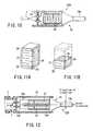
- FIG. 10shows a sixth modification of the ultrasonic transducer unit 22A that is incorporated in the ultrasonic treatment device 2, i.e., the first embodiment of this invention.
- the horn 15, piezoelectric element 16, electrodes 49a and 49b and connecting plate 17are fastened together with a bolt, constituting a langevin transducer.
- the sixth modified transducer unit 22Gis different in that the piezoelectric element 26 is adhered to the horn 15 as is illustrated in FIG. 10 .
- the sixth modified transducer unit 22Ghas a more simple structure.
- FIG. 11Ashows the multi-layered piezoelectric element 26 used in the sixth modified transducer unit 22G.
- the multi-layered piezoelectric element 26is composed of one outer electrode 29 and two insulating protective layers 30, which have been formed integral by means of sintering. When supplied with an electric signal, the piezoelectric element 26 vibrates at ultrasonic frequency.
- FIG. 11Bdepicts another type of a multi-layered piezoelectric element 26 for use in the sixth modified ultrasonic transducer 22G.
- This multi-layered piezoelectric element 26is composed of a piezoelectric layer 27, one inner electrode 28, one outer electrode 29 and one insulating protective layer 30, which have been formed integral by means of sintering.
- the ultrasonic transducer unit 22A and the modified ultrasonic transducer units 22B to 22Gvibrate in their axial direction, performing longitudinal vibration. Other vibration may be more effective than longitudinal vibration in some cases, depending on the shape and condition of the tissue to be treated.
- FIGS. 12 and 13illustrate a seventh modification 22H of the ultrasonic transducer unit 22A that is incorporated in the ultrasonic treatment device 2, i.e., the first embodiment of this invention.
- the seventh modified transducer unit 22Hcan vibrate in the direction perpendicular to the axial direction, thus achieving transverse vibration.
- the ultrasonic transducer unit 22H shown in FIGS. 12 and 13has an element-supporting member 15d integrally formed with the rear end of the horn 15.
- the element-supporting member 15dis shaped like a plate and extends in the axial direction of the horn 15.
- Two vibrators 31 and 32are mounted on the upper and lower surfaces of the element-supporting member 15d.
- the plate-shaped vibrators 31 and 32oppose each other across the element-supporting member 15d.
- a negative (-) electrode 31bis interposed between the plate-shaped vibrator 31 and the element-supporting member 15d
- a negative (-) electrode 32ais interposed between the plate-shaped vibrator 32 and the element-supporting member 15d.
- Two positive (+) electrodes 31a and 32bare mounted on the outer surfaces of the vibrators 31 and 32, respectively.
- the plate-shaped vibrators 31 and 32are therefore polarized in the direction of arrows as illustrated in FIGS. 12 and 13 .
- a negative (-) conductor 19bis connected to the negative (-) electrodes 31b and 32a that contact the element-supporting member 15d.
- a positive (+) conductor 19ais connected to the positive (+) electrodes 31a and 32b that oppose the transducer cover 18.
- the conductors 19a and 19bserve to generate transverse vibration. Transverse vibration works well to crush, for example, stones in body cavities.
- FIG. 14shows an eighth modification 22I of the ultrasonic transducer unit 22A that is incorporated in the ultrasonic treatment device 2, i.e., the first embodiment of this invention.
- the eighth modified transducer unit 22Ihas two multi-layered piezoelectric elements 33 and 34 that are can adhere to the horn 15. As indicated by the arrows in FIG. 14 , the multi-layered piezoelectric elements 33 and 34 are polarized in the opposite directions.
- a positive (+) conductor 19ais connected to one external electrode 35 of the element 33 and one external electrode of the element 34, and a negative (-) conductor 19b is connected to the other external electrode (not shown) of the element 33 and the other external electrode (not shown) of the element 34.
- the modified transducer unit 22Igenerates transverse vibration.
- FIGS. 15 and 16show a ninth modification 22J of the ultrasonic transducer unit 22A that is incorporated in the ultrasonic treatment device 2, i.e., the first embodiment of this invention.
- the ninth modified transducer unit 22Jhas two torsional-vibration transducers 37 that are shaped like a ring.
- each torsional-vibration transducer 37is composed of segments 37a. It has been made by cutting a ring into segments 37a, polarizing each segment 37a in the direction indicated by an arrow in FIG. 16 , and bonding the segments 37 to each other to form a ring.
- the torsional-vibration transducers 37are fastened to the horn 15 such that they are polarized in the opposite directions.
- the ninth modified transducer unit 22Jcan generate torsional vibration in the circumferential direction of the transducers 37.
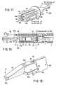
- FIG. 17illustrates a tenth modification 22K of the ultrasonic transducer unit 22A that is incorporated in the ultrasonic treatment device 2, i.e., the first embodiment of this invention.
- the ninth modified transducer unit 22Khas four multi-layered piezoelectric elements 38 to 41.
- the piezoelectric elements 38 to 41are polarized in the directions of the arrows shown in FIG. 17 .
- the piezoelectric elements 38 to 41are arranged, opposing one another.
- Four outer electrodes 51 amounted on the piezoelectric elements 38 to 41are connected to a positive (+) conductor 19a.
- Two negative (-) electrodes 52interposed, respectively, between the piezoelectric elements 38 and 39 and between the piezoelectric elements 40 and 41. Both negative (-) electrodes 52 are connected to a negative (-) conductor 19b.
- the modified transducer unit 22Kcan therefore generate vibration.
- FIGS. 18 to 20show a second embodiment of this invention.
- the components that are identical to those of the first embodimentwill be designated at the same reference numerals and will not be described. Only the components different from those of the first embodiment will be described.
- the ultrasonic treatment devicehas a flexible sheath 3, an ultrasonic transducer unit 22L, and a forceps 42.
- the transducer unit 22Lis coupled to the distal end of the flexible sheath 3. It has a horn 15, which in turn has a treatment member 15b.
- the forceps 42is attached to the distal end of the ultrasonic transducer unit 22L.
- the forceps 42has a holding part 42a, a rear end part 42c, and a supporting part 42b.
- the holding part 42ahas a holding surface f that may contact the treatment member 15b of the horn 15.
- the rear end portion 42cis formed integral with the rear end of the holding part 42a.
- the supporting part 42bis provided on one side of the holding part 42a and formed integral with the holding part 42a.
- An operation wire 43is connected, at one end, to the rear end portion 42c.
- the horn 15has a hole 44, through which the operation wire 43 passes.
- a cover 15cis formed integral with the rear end of the treatment member 15b. The cover 15c performs the same function as the transducer cover 18 that has been described with reference to FIG. 2 . Note that in the first embodiment, the transducer cover 18 may have a hole through which an operation wire can pass.
- the hole 44is made in the cover 15c that is integral with the rear end of the treatment member 15b.
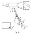
- the operation wire 43passes through the cap 4b of an endoscope 1 and extends to the operation unit 6 of the endoscope 1, as is illustrated in FIG. 20 .
- the operation wire 43is connected, at proximal end, to a handle 53.
- support pins 45couples the supporting part 42b of the forceps 42 to the cover 15c of the horn 15, allowing the supporting part 42b to rotate.
- the handle 53can slide in the axial direction of the shaft portion 6S of the operation unit 6.
- the operation wire 43moves the rear end portion 42c of the forceps 42 back and forth. So moved, the wire 43 rotates the forceps 42 around the support pins 45, in the direction of the arrows shown in FIG. 19 . As a result, the holding part 42a of the forceps 42 can open and close.
- the doctorinserts the distal end portion 1C3 of the endoscope 1 into the tubular cavity in the subject.
- lightis applied to the wall of the cavity from the illumination lenses 50.
- the doctorcan observe the interior of the cavity on the video monitor.
- the doctorinserts the ultrasonic treatment device 2 from the cap 4b of an endoscope 1 into the tubular cavity.
- the forceps 42remains closed, abutting on the treatment member 15b of the horn 15.
- the doctorinserts first the cover 15C and then the flexible sheath 3, from the cap 4b into the channel 23 of the endoscope 1.
- the doctormoves the handle 53 forth, while observing the interior of the cavity through the endoscope 1. After the device 2 enters the cavity, the doctor moves the handle 53 forth further, until the treatment member 15b of the horn 15 abuts on the affected tissue to be treated. Note that the horn 15 is attached to the distal end of the transducer unit 22L.
- the doctorpulls the handle 53 and rotates the handle 53, opening the forceps 42. That is, the holding part 42a of the forceps 42 moves away from the treatment member 15b of the horn 15. Then, the doctor pushes the operation unit 6, maintaining the forceps 42 open. The affected living tissue is thereby clamped between the treatment member 15b and the holding part 42a.
- the doctorturns on the switch (a foot switch or a hand switch) to generate ultrasonic vibration.
- a drive signalis supplied from the transducer drive unit 9 via the signal cable 7 to the piezoelectric element 16 of the ultrasonic transducer unit 22A.
- the piezoelectric element 16converts the drive signal, i.e., an electric signal, to ultrasonic vibration.
- the ultrasonic vibrationpropagates to the treatment member 15b of the horn 15.
- the doctorpushes the handle 53, clamping the living tissue between the treatment member 15b and the holding part 42a. Now clamped between the treatment member 15b and the holding part 42a, the living tissue can be crushed, emulsified or coagulated to stop bleeding as the treatment member 15b at the distal end of the horn 15 undergoes ultrasonic vibration.
- the second embodimentis advantageous in some respects.
- the flexible sheath 3can be deformed in the same way as the bending portion 1C2 of the endoscope 1 is bent, because the ultrasonic transducer unit 22L is coupled to the distal end of the flexible sheath 3. So deformed, the sheath 3 would not hinder the bending of the portion 1C2 of the endoscope 1.
- the treatment member 15b provided at the distal end of the horn 15can easily protrude from, and receded into, the distal end of the channel 23 as the doctor moves the handle 53 back and forth on the operation unit 6.
- the first embodimentenables the doctor to apply ultrasonic vibration to a living tissue reliably, because the forceps 42 and the treatment member 15b can clamp the living tissue.
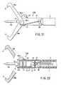
- FIG. 21 and 22illustrate an ultrasonic treatment device that is a third embodiment of the present invention.
- the components that are identical to those of the first embodimentwill be designated at the same reference numerals and will not be described. Only the components different from those of the first embodiment will be described.
- the ultrasonic treatment devicei.e., the third embodiment, has a flexible sheath 3, an ultrasonic transducer unit 22M, a transducer cover 18, and two (a pair of) forceps 46a and 46b.
- the ultrasonic transducer unit 22Mis coupled to the distal end of the flexible sheath 3.
- the forceps 46a and 46bhave a claw g each at the free end. They have rear end parts 46a1 and 46b1, respectively.
- Two support pins 55couple the rear end part 46a1 and 46b1 to the transducer cover 18, allowing the forceps 46a and 46b to rotate.
- Two operation wires 47are fastened to the rear end part 46a1 of the forceps 46a and the rear end part 46b1 of the forceps 46b, respectively.
- the wires 47are inserted into the flexible sheath 3 through the U-notches 48 cut in the transducer cover 18.
- the wires 47extend through the flexible sheath 3 and are connected to the handle 53 ( FIG. 20 ) provided on the operation unit 6 of an endoscope.
- the handle 53can slide back and forth on the shaft portion 6S of the operation unit 6.
- the operation wires 47are moved back and forth.
- the forceps 46a and 46brotate around the support pins 55 in the opposite directions.
- the claws g at the distal ends of the forceps 46a and 46bcan open and close the treatment member 15b.
- the doctorinserts the distal end portion 1C3 of the endoscope 1 into the tubular cavity in the subject.
- lightis applied to the wall of the cavity from the illumination lenses 50.
- the doctorcan observe the interior of the cavity on the video monitor.
- the doctorinserts the ultrasonic treatment device 2 from the cap 4b of an endoscope 1 into the tubular cavity.
- the forceps 46a and 46b of the device 2are held in the closed position.
- the doctorinserts the horn 15, the forceps 46a and 46b, the transducer cover 18 and the flexible sheath 3, in the order they are mentioned, from the cap 4b into the channel 23 of the endoscope 1.
- the doctormoves the handle 53 forth, while observing the interior of the cavity through the endoscope 1. After the device 2 enters the cavity, the doctor moves the handle 53 forth further, until the treatment member 15b of the horn 15 abuts on the affected tissue to be treated. It should be noted that the horn 15 is attached to the distal end of the transducer unit 22M.
- the doctorpulls the handle 53 and rotates the handle 53, opening the forceps 46a and 46b. Namely, the forceps 46a and 46b moves away from the treatment member 15b of the horn 15. Then, the doctor pushes the operation unit 6, maintaining the forceps 46a and 46b open. The affected living tissue is thereby clamped between the claws g of the forceps 46a and 46b.
- the doctorAfter clamping the tissue, the doctor turns on the switch (a foot switch or a hand switch) to generate ultrasonic vibration. Then, a drive signal is supplied from the transducer drive unit 9 via the signal cable 7 to the piezoelectric element 16 of the ultrasonic transducer unit 22A.
- the piezoelectric element 16converts the drive signal, i.e., an electric signal, to ultrasonic vibration.
- the ultrasonic vibrationpropagates to the treatment member 15b of the horn 15.
- the doctorfurther pulls the handle 53, squeezing the living tissue between the claws g of the forceps 46a and 46b.
- the living tissuecan be cut or coagulated to stop bleeding as the treatment member 15b undergoes ultrasonic vibration.
- the second embodimentis advantageous in some respects.
- the flexible sheath 3can be deformed in the same way as the bending portion 1C2 of the endoscope 1 is bent, because the ultrasonic transducer unit 22M is coupled to the distal end of the flexible sheath 3. So deformed, the sheath 3 would not hinder the bending of the portion 1C2 of the endoscope 1.
- the treatment member 15b provided at the distal end of the horn 15 of the unit 22Mcan easily protrude from, and receded into, the distal end portion 1C3 of the endoscope 1 as the doctor moves the handle 53 back and forth on the operation unit 6.
- the third embodimentmakes it easier for the doctor to perform ultrasonic treatment on the living tissue as is desired.
Landscapes
- Health & Medical Sciences (AREA)
- Surgery (AREA)
- Engineering & Computer Science (AREA)
- Life Sciences & Earth Sciences (AREA)
- Biomedical Technology (AREA)
- Molecular Biology (AREA)
- Vascular Medicine (AREA)
- Orthopedic Medicine & Surgery (AREA)
- Mechanical Engineering (AREA)
- Heart & Thoracic Surgery (AREA)
- Medical Informatics (AREA)
- Nuclear Medicine, Radiotherapy & Molecular Imaging (AREA)
- Animal Behavior & Ethology (AREA)
- General Health & Medical Sciences (AREA)
- Public Health (AREA)
- Veterinary Medicine (AREA)
- Surgical Instruments (AREA)
- Ultra Sonic Daignosis Equipment (AREA)
Abstract
Description
- The present invention relates to an ultrasonic treatment device for use in combination with endoscopes, and to an ultrasonic treatment system.
U.S. Patent 6,231,578 discloses an ultrasonic treatment device to be inserted into the channel of an endoscope and thereby to be inserted into a patient. This apparatus is guided into the view field of the endoscope and used to treat the living tissues in the patient. The apparatus has a flexible wire, a tubular sheath and an operation unit. The flexible wire has a loop on its distal end. The flexible wire extends through the tubular sheath and can slide in the sheath. The operation unit is coupled to the proximal end of the tubular sheath. The operation unit has an actuator and an ultrasonic transducer. The actuator can move the flexible wire in the axial direction of the tubular sheath. The ultrasonic transducer can generate ultrasonic vibration. The ultrasonic vibration generated by the transducer is transmitted to the flexible wire.- When driven, the actuator moves the flexible wire along the axis of the tubular sheath. If the wire is pulled toward the proximal end of the sheath, the loop will go into the sheath and will close. If the wire is pushed toward the distal end of the sheath, the loop will protrude from the sheath and will open. Assume that the loop is wrapped around a tumor such as polyp while it is opening. Also, assume that the wire is pulled toward the proximal end of the sheath. Then, the loop closes and holds the tumor. In this condition, ultrasonic vibration may be transmitted from the ultrasonic transducer to the flexible wire, thereby cutting the tumor.
- Jpn. Pat. Appln. KOKAI Publication No.
11-56867 - In the apparatus disclosed in
U.S. Patent 6,231,578 , the treatment unit is a loop and cannot cut any tumor larger than the loop. The treatment unit cannot cut tumors that do not project. Nor can it cut blood vessels or tighten blood vessels to stop bleeding. Thus, the use of the apparatus is limited very much. Since the ultrasonic vibration that the transducer generates is transmitted to the flexible wire, i.e., a long flexible probe, part of the vibration energy turns into heat. Consequently, the loop at the distal end of the wire may not be vibrated at so large amplitude as is desired. - The apparatus may be used in combination with flexible endoscopes whose channel is often bent while being used. In this case, the vibration stress on the wire (i.e., ultrasonic probe) is large not only in the bent part of the channel, but also in any other part thereof. Hence, the wire needs to be strong enough to withstand the stress. Note that the wire may damage the inner surface of the channel of the endoscope when it is bent.
- The apparatus disclosed in Jpn. Pat. Appln. KOKAI Publication No.
11-56867 U.S. Patent 6,231,578 . However, the support rod is rigid, not flexible. The apparatus cannot be used in combination with flexible endoscopes. Since the support rod is connected to the ultrasonic transducer, but not at any node of ultrasonic vibration. This results in a loss of vibration energy. Inevitably, the blade cannot be vibrated at so large amplitude as is desired. - The ultrasonic transducer used in the apparatus of disclosed in Jpn. Pat. Appln. KOKAI Publication No. 11-56867 is a piezoelectric element or a magnetostrictive element. Both elements are harmful in most cases. The transducer should therefore be sheathed. The transducer is exposed to the tissue to be treated, however, even if a guide wire is used in place of the support rod. To the patient, the apparatus is not so safe as desired.
US- B - 6 379 320 discloses an ultrasound treatment-device where axial- or longitudinal movement of an ultrasound-body, placed on the distal end of a sheath- or tubular element, is obtained by inserting a guidewire into a groove of the ultrasound-body.- The present invention has been made in view of the foregoing. An object of the invention is to provide an ultrasonic treatment device designed for use in combination with an endoscope and an ultrasonic treatment system having the apparatus. The apparatus can be inserted in part into a tubular cavity, along with the channel of an endoscope. It can apply ultrasonic vibration to the affected tissues in the tubular cavity, enabling the doctor to cut or coagulate the tissues while observing the tissue through the endoscope.
- According to the invention, there is provided an ultrasonic treatment device as defined in
claim 1 that comprises: - an ultrasonic transducer unit having an ultrasonic transducer and a cover member which covers the ultrasonic transducer; a flexible sheath having a distal end part and a proximal end part, the distal end part being coupled to the cover member; a signal cable which extends through the sheath and which has a distal end part and a proximal end part, the distal end part being connected to the ultrasonic transducer; a transducer drive unit which is connected to the proximal end part of the signal cable and configured to generate a drive signal for driving the ultrasonic transducer; an operation unit which is provided at the proximal end part of the sheath and configured to move, when operated by a doctor, the sheath in an axial direction to move the ultrasonic transducer unit in the axial direction of the sheath.
- Preferably, the ultrasonic transducer has an axis, a main part, a horn and a treatment member. The horn has a distal end part and a proximal end part that is coupled to the main part and is configured to amplify ultrasonic vibration generated by the main part. The ultrasonic vibration is applied to the distal end part. The treatment member is provided at the distal end part of the horn to abut on a living tissue to perform an ultrasonic treatment on the living tissue. The ultrasonic transducer unit has a fastening member. The fastening member secures the cover member at a vibration node of the ultrasonic transducer.
- It is desired that the treatment member be located at a 1/4-wavelength distance from the fastening member that secures the cover member.
- Preferably, the main part of the ultrasonic transducer has a plurality of piezoelectric elements that convert an electric signal to mechanical vibration, a plurality of electrodes that supply an electric signal to the piezoelectric elements, and a connecting plate; the cover member is positioned preferably at the vibration node of the ultrasonic transducer and interposed between the horn and the piezoelectric elements; and the ultrasonic transducer unit has an embedded bolt that fastens the horn, cover member, piezoelectric elements, electrodes and connecting plate to one another.
- It is desired that the horn and the cover member be formed integral with each other in the ultrasonic transducer unit.
- Preferably, the main part of the ultrasonic transducer has piezoelectric layers, inner electrodes and outer electrodes, which are alternately, laid one upon another.
- Preferably, the ultrasonic transducer has a main part. The main part is a transverse vibrator that vibrates in a direction perpendicular to the axis of the ultrasonic transducer.
- It is desired that the ultrasonic transducer should have a torsional-vibration main part that vibrates in a circle around the axis.
- It is preferred that the signal cable should have a connector at the proximal end part. The connector can be connected to the transducer drive unit.
- Preferably, the operation unit has a cable-guiding port through which the signal cable is guided, and the signal cable thus guided is connected to the transducer drive unit.
- It is preferred that the signal cable should have a connector at an end part which protruding from the cable-guiding port. The connector can be connected to the transducer drive unit.
- It is desired that the ultrasonic transducer unit should have a forceps member that s rotatably coupled to the cover member; the forceps member should have support pins that are rotatably supported by the cover member and a holding part that contacts and leaves the horn when rotated around the support pins; an operation wire should extend through the flexible sheath to operate the forceps member and has a proximal end part and a distal end part which is connected to the forceps member; and the operation unit should have a guide portion that extends in the axial direction of the operation wire and a handle that is mounted on the guide portion so as to be moved back and forth and which is connected to the proximal end part of the operation wire to pull and slacken the operation wire, thereby to move the forceps member to and from the horn.
- It is desired that the signal cable should have a connector at the proximal end part, and that the connector should be able to be connected to the transducer drive unit.
- It is desired that the forceps member be supported to clamp a living tissue between the holding part and the proximal end part of the horn.
- Preferable, the ultrasonic transducer unit has a pair of forceps members that are arranged at two sides of the horn, respectively, and which are rotatably coupled to the cover member; the forceps members have a support pin and a holding part each, the support pin being rotatably coupled to the cover member and the holding part contacting and leaving the horn as the forceps member is rotated around the support pin; and each of the forceps members is supported such that a living tissue is clamped between the holding part and the horn.
- According to this invention there is also provided an ultrasonic treatment system as defined in
claim 16 that has an ultrasonic treatment device, and an endoscope used in combination with the ultrasonic treatment device. The ultrasonic treatment device comprises: an ultrasonic transducer unit having an ultrasonic transducer designed to treat a living tissue, and a cover member that covers the ultrasonic transducer; a flexible sheath that has a distal end part and a proximal end part, the distal end part being coupled to the cover member; a signal cable that has a distal end part and a proximal end part, the distal end part being connected to the ultrasonic transducer; a transducer drive unit that is connected to the proximal end part of the signal cable and designed to generate a drive signal for driving the ultrasonic transducer; an operation unit that is provided at the proximal end part of the sheath and designed to move the sheath, thereby to move the ultrasonic transducer unit in an axial direction of the sheath. The endoscope includes an elongate insertion unit that is to be inserted into a body cavity and has at least one channel. The cover member and flexible sheath of the ultrasonic treatment device have outside diameters smaller than the inside diameter of the channel of the endoscope. The ultrasonic transducer unit is designed to move into and from the channel of the endoscope when the operation unit is moved in the axial direction of the sheath. - The ultrasonic transducer unit and flexible sheath of an ultrasonic treatment device can be inserted into a body cavity, while being held in the channel of an endoscope. The ultrasonic transducer unit can protrude from and recede into the distal end of the endoscope. While protruding from the endoscope, the ultrasonic transducer unit can apply ultrasonic vibration to the living tissues in the body cavity. Thus, the device enables a doctor to cut and coagulate the living tissues.
- An ultrasonic treatment device according to an embodiment has an ultrasonic transducer unit and a forceps member. The forceps member opposes the distal end part of the ultrasonic transducer unit and can therefore reliably hold any living tissue. Hence, the device enables a doctor to perform an ultrasonic treatment on the living tissue.
- An ultrasonic treatment device according to the invention can be inserted into a body cavity, while being held in the channel of an endoscope. Therefore, it enables a doctor to can cut and coagulate living tissues in the body cavity, while observing the tissues through the endoscope.
- This summary of the invention does not necessarily describe all necessary features so that the invention may also be a sub-combination of these described features.
- The invention can be more fully understood from the following detailed description when taken in conjunction with the accompanying drawings, in which:
FIG. 1 is a schematic representation of an endoscope that has an ultrasonic treatment device according to a first embodiment of this invention;FIG. 2 is a magnified sectional showing the distal end portion of the endoscope and the distal end portion of the ultrasonic treatment device;FIG. 3A is a perspective view depicting the distal end portion of the endoscope and that of the ultrasonic treatment device;FIG. 3B is a side view showing the knife-shaped distal end of a horn that may be mounted on the ultrasonic transducer incorporated in the ultrasonic treatment device;FIG. 3C is a side view showing the hook-shaped distal end of a horn that may be mounted on the ultrasonic transducer;FIG. 4 is a longitudinal sectional view illustrating how the horn is fitted in the transducer cover in the ultrasonic treatment device according to the first embodiment;FIG. 5 is a transverse sectional view showing how the horn is fitted in the transducer cover in a first modification of the first embodiment;FIG. 6 is a longitudinal sectional view showing how the horn is fitted in the transducer cover in a second modification of the first embodiment;FIG. 7 is a longitudinal sectional view showing how the horn is fitted in the transducer cover in a third modification of the first embodiment;FIG. 8 is a longitudinal sectional view showing how the horn is fitted in the transducer cover in a fourth modification of the first embodiment;FIG. 9 is a longitudinal sectional view illustrating the ultrasonic transducer provided in a fifth modification of the fist embodiment;FIG. 10 is a longitudinal sectional view depicting the ultrasonic transducer used in a sixth modification of the first embodiment;FIG. 11A is a perspective view representing the multi-layered piezoelectric element used in the ultrasonic transducer incorporated in the modification shown inFIG. 10 ;FIG. 11B is a perspective view representing another type of a multi-layered piezoelectric element that may be used in the ultrasonic transducer incorporated in the modification shown inFIG. 10 ;FIG. 12 is a longitudinal sectional view showing the ultrasonic transducer used in a seventh modification of the first embodiment;FIG. 13 is a perspective view depicting the plate-shaped vibrating member of the ultrasonic transducer shown inFIG. 12 ;FIG. 14 is a perspective view illustrating the ultrasonic transducer provided in an eighth modification of the first embodiment;FIG. 15 is a perspective view showing the ultrasonic transducer provided in a ninth modification of the first embodiment;FIG. 16 is a perspective view depicting the torsional-vibration piezoelectric element incorporated in the ultrasonic transducer shown inFIG. 15 ;FIG. 17 is a perspective view showing the ultrasonic transducer provided in a tenth modification of the first embodiment;FIG. 18 is a longitudinal sectional view illustrating the distal end portion of an ultrasonic treatment device according to a second embodiment of the invention;FIG. 19 is a perspective view showing the distal end portion of the second embodiment;FIG. 20 is a side view of the operation unit and handle of the second embodiment, the handle shown with a part cut away;FIG. 21 is a front view of the distal end portion of an ultrasonic treatment device according to a third embodiment of the present invention; andFIG. 22 is a longitudinal sectional view illustrating the distal end portion of the ultrasonic treatment device according to the third embodiment.FIG. 1 to 4 show the first embodiment of the present invention.FIG. 1 is a schematic representation of anendoscope 1 that may be used in combination with anultrasonic treatment device 2. Theendoscope 1 has aninsertion unit 1B and anoperation unit 1A. Theinsertion unit 1B is a long tube that may be inserted into a tubular cavity in the subject. Theoperation unit 1A is coupled to the proximal end of theinsertion unit 1B. Theinsertion unit 1B has a tubular portion 1C1, a bending portion 1C2, and a distal end portion 1C3. The flexible tubular portion 1C1 is a long flexible tube. Its proximal end is coupled to theoperation unit 1A. The bending portion 1C2 is connected at one end to the distal end of the tubular portion 1C1. The distal end portion 1C3 is connected to the other end of the bending portion 1C2.- As
FIG. 2 shows, the bending portion 1C2 contains a plurality ofsegments 12. Thesegments 12 are arranged in the axial direction of the bending portion 1C2. They are coupled so that each may rotate with respect to the adjacent ones. Wires (not shown) extend through the tubular portion 1C1 and the bending portion 1C2. The wires are connected at one end to thesegments 12, respectively, and at the other end to theoperation unit 1. They can be pulled and slackened as theoperation unit 1 is operated, to rotate thesegments 12. If thesegments 12 are so rotated, the bending portion 1C2 will be bent. - As
FIG. 3A shows, an observation lens (observation means) 13 and two illumination lenses (illumination means) 50 are provided in the distal end of the distal end portion 1C3. Thedistal end 23a of achannel 23 opens at the distal end of the distal end portion 1C3. As illustrated inFIG. 2 , animage guide 14 has its distal end lying behind theobservation lens 13 and opposing thislens 13. An imaging element such as a CCD may be arranged at the back of theobservation lens 13, more precisely at the focus of thelens 13. Then, the imaging element can convert the image of an object formed by thelens 13 into an electric signal. At the back of theillumination lenses 50, the distal end of a light guide (not shown) is positioned, opposing bothillumination lenses 50. - The
insertion unit 1B contains an image guide, the light guide (not shown), and thechannel 23, in addition to the wires (not shown) to be operated to bend the bending portion 1C2. Note that the image guide may be replaced by a signal cable if an imaging element is arranged at the back of theobservation lens 13. - The
operation unit 1A has a tube-bendingknob 4a and acap 4b. The tube-bendingknob 4a is coupled to a bending mechanism (not shown) that is incorporated in theoperation unit 1A. It is to this bending mechanism that the wires for bending the bending portion 1C2 are connected. As theknob 4a is rotated, the wires are pulled and slackened to rotate thesegments 12 and, hence, bend the bending portion 1C2. - The
channel 23 has its proximal end coupled to thecap 4b. From thecap 4b, various treatment devices, such as forceps, theultrasonic treatment device 2 and the like, can be inserted into thechannel 23. Any treatment device thus inserted into thechannel 23 may protrude from thedistal end 23a of achannel 23. - A
universal code 10 is connected, at one end, to theoperation unit 1A. At the other end, theuniversal code 10 has a connector, which is connected to a light source (not shown) and a video camera (not shown, either) . - The
ultrasonic treatment device 2, i.e., the first embodiment of the invention, has aflexible sheath 3, anoperation unit 6, and anultrasonic transducer unit 22A. Theoperation unit 6 is coupled to the proximal end of theflexible sheath 3. Theultrasonic transducer unit 22A is coupled to the distal end of theflexible sheath 3. - The
flexible sheath 3 is a double-layer tube. The double-layer tube is composed of aninner layer 3a and anouter layer 3b. A reinforcing member is interposed between theinner layer 3a and theouter layer 3b. Alternatively, the reinforcing member may be embedded in either theinner layer 3a or theouter layer 3b. Theultrasonic transducer unit 22A is inserted in theflexible sheath 3. - As seen from
FIG. 2 , theultrasonic transducer unit 22A has anultrasonic transducer 16A and a hollow-cylindrical transducer cover (cover member) 18. Theultrasonic transducer 16A has a piezoelectric element (transducer body) 16, a negative (-)electrode 49a, a positive (+)electrode 49b, ahorn 15, and a connectingplate 17. Thehorn 15 has aflange 15a and atreatment member 15b. Theflange 15a lies at a node of vibration. Thetreatment member 15b has its distal face b located at the anti-node of vibration. The connectingplate 17 is made of metal and firmly secures thetreatment member 15b to that end of thehorn 15 that opposes theflange 15a. - The
transducer cover 18 covers the entirety of theultrasonic transducer 16A, except thehorn 15. Thetransducer cover 18 has two holes in the rear end, into which electrically conductive pins can be inserted. - Two electrically
conductive pins 20 project backwards from the proximal end of theultrasonic transducer 16A. Theseconductive pins 20 are inserted in the two holes made in the rear end of thetransducer cover 18, respectively. An insulatingsheath 21 is provided on each electricallyconductive pin 20. Thesheath 21 fills the gap between the electricallyconductive pin 20 and the hole made in thetransducer cover 18. - Each electrically
conductive pin 20 is connected, at inner end, coupled to one end of aconductor 19 that supplies electric power to thepiezoelectric element 16. The twoconductors 19 are connected, at the other end, to the negative (-)electrode 49a and positive (+)electrode 49b of thepiezoelectric element 16, respectively. - The
transducer cover 18 is connected to theflexible sheath 3. Thetransducer cover 18 and theflexible sheath 3 have almost the same outside diameter. The diameters of thetransducer cover 18 andflexible sheath 3 are smaller than the inside diameter of thechannel 23. Theultrasonic transducer unit 22A and theflexible sheath 3 can therefore pass through thechannel 23. - The
flexible sheath 3 is a little longer than thechannel 23. Theultrasonic transducer unit 22A can therefore protrude from, and recede into, the distal end portion 1C3 of theendoscope 1, when theoperation unit 6 is moved back and forth. - The above-mentioned
signal cable 7 is connected, at distal end, to the outer ends of both electrically conductive pins 20. Thesignal cable 7 extends through theflexible sheath 3, reaching theoperation unit 6. Thesignal cable 7 has its proximal end portion extending outwards through acable outlet port 5. To the proximal end of thesignal cable 7 there is connected aconnector 8 at one end. Theconnector 8 is connected, at the other end, to atransducer drive unit 9. Theultrasonic transducer unit 22A can receive drive signals from thetransducer drive unit 9. - The
treatment member 15b of thehorn 15 may be a knife-shaped one 15b1 shown inFIG. 3B or a hook-shaped one shown inFIG. 3C . Themember 15b may have any other type, nonetheless, so long as it can perform its function. AsFIG. 2 depicts, the front b of thetreatment member 15b is located at an anti-node of vibration. Theflange 15a secured to thetransducer cover 18 is positioned at a node of vibration. The front b of thetreatment member 15b is spaced from theflange 15a by a distance of 1/4 wavelength. FIG. 4 illustrates how thehorn 15 is fitted in thetransducer cover 18. Theflange 15a of thehorn 15 is relatively long in the axis of thehorn 15. Theflange 15a has a male screw k cut in its peripheral surface. Thetransducer cover 18 has a female screw m cut in the inner peripheral surface of its distal end portion. The male screw k meshes with the female screw m. Thus, theflange 15a of thehorn 15 is secured to thetransducer cover 18.- How the
ultrasonic treatment device 2, which is the first embodiment of the invention, operates will be described. To use theultrasonic treatment device 2, the doctor inserts theinsertion unit 1B of the endoscope 1 (FIG. 1 ) into a tubular body cavity of the subject, first the distal end portion 1C3 of theinsertion unit 1B. The doctor inserts theinsertion unit 1B, while observing an image of the body- cavity interior, obtained through theobservation lens 13 and displayed on a video monitor. Note that the interior of the body cavity is illuminated with the light applied through theillumination lenses 50. After locating an effected tissue in the body cavity, the doctor inserts theultrasonic treatment device 2 into the body cavity through thecap 4b of theoperation unit 1A. - More specifically, the doctor first inserts the
horn 15, then thetransducer cover 18 and finally theflexible sheath 3, into thechannel 23 through thecap 4b. At this time, the doctor moves theoperation unit 6 back and forth, bringing thetreatment member 15b on thehorn 15 to the affected tissue that should be treated. Then, the doctor moves theoperation unit 6 again, causing thetreatment member 15b to contact the affected tissue. - Then, the doctor turns on a switch (not shown) to generate ultrasonic vibration. More precisely, he or she turns on a foot switch or a hand switch. While the switch remains on, a drive signal is supplied from the
transducer drive unit 9 via thesignal cable 7 to thepiezoelectric element 16 of theultrasonic transducer unit 22A. Thepiezoelectric element 16 converts the drive signal, i.e., an electric signal, to ultrasonic vibration. The ultrasonic vibration propagates to thehorn 15. Hence, thetreatment member 15b provided at the distal end of thehorn 15 applies the ultrasonic vibration to the affected tissue. The tissue is thereby crushed, is emulsified or is coagulated to stop bleeding. - Configured as described above, the
ultrasonic treatment device 2 is advantageous in some respects. First, thetransducer cover 18 covering thehorn 15 and theflexible sheath 3 coupled to thecover 18 have outside diameters smaller than the inside diameter of thechannel 23 of theendoscope 1. Second, once theultrasonic transducer unit 22A has been inserted into thechannel 23, thetreatment member 15b provided at the distal end of thehorn 15 can protrude from, and receded into, the distal end of thechannel 23 as theoperation unit 6 is moved back and forth. Therefore, thetreatment member 15b can cut or coagulate the living tissue while it is undergoing ultrasonic vibration. - In addition, the doctor can cut or coagulate a living tissue by touching the tissue with the
treatment member 15b undergoing ultrasonic vibration. Thus, the doctor can cut tumors relatively large and tumors not projecting, can cut the blood vessels and can stop bleeding at such tumors and the blood vessels. In other words, theultrasonic treatment device 2 can be used to accomplish various medical treatments in body cavities. - Further, the
flexible sheath 3 can be deformed in the same way as the bending portion 1C2 of theendoscope 1, because theultrasonic transducer unit 22A is coupled to the distal end of theflexible sheath 3 that is a long tube. This makes it possible to bend the portion 1C2 of theendoscope 1 smoothly and makes it easy to project thetreatment member 15b from, and pull it into, the distal end portion 1C3 of theendoscope 1. - Moreover, the components of the
ultrasonic transducer 16A, such as thepiezoelectric element 16, are not exposed since the hollowcylindrical transducer cover 18 covers all the components of thetransducer 16A, except thehorn 15. This renders theultrasonic treatment device 2 safer to the subject. FIG. 5 shows a first modification of theultrasonic transducer unit 22A that is incorporated in theultrasonic treatment device 2, i.e., the first embodiment of this invention. In this modifiedtransducer unit 22B, thehorn 15 is secured to thetransducer cover 18 by laser welding. That is, a laser beam is applied to the interface between theflange 15a and thetransducer cover 18, thereby welding thehorn 15 to thetransducer cover 18. AsFIG. 5 shows, theflange 15a has flat surfaces and thecover 18 has flat inner surfaces 18a1 and 18a2. These flat surfaces make it easy to position thehorn 15 and thecover 18 with respect to each other in preparation for the laser welding.FIG. 6 depicts a second modification of theultrasonic transducer unit 22A that is incorporated in theultrasonic treatment device 2, i.e., the first embodiment of this invention. In the second modifiedtransducer unit 22C, thehorn 15 is secured to thetransducer cover 18 by means of screws. More precisely, screws 54 are driven into theflange 15 though the holes made in thetransducer cover 18, thus fastening theflange 15a to thetransducer cover 18.FIG. 7 depicts a third modification of theultrasonic transducer unit 22A that is incorporated in theultrasonic treatment device 2, i.e., the first embodiment of this invention. In this modifiedtransducer unit 22D, the distal end portion of thetransducer cover 18 is bent, forming abent part 18a. Thebent part 18a is clamped between thehorn 15 and thepiezoelectric element 16. An embeddedbolt 25 fastens thehorn 15,transducer cover 18,piezoelectric element 16,electrodes plate 17 to one another. Thus, the components of thetransducer unit 22D can be fastened together and thetransducer cover 18 can be secured, by using one bolt only, i.e., the embeddedbolt 25.FIG. 8 shows a fourth modification of theultrasonic transducer unit 22A that is incorporated in theultrasonic treatment device 2, i.e., the first embodiment of this invention. In the fourth modifiedtransducer unit 22E, thehorn 15 has a hollowcylindrical cover 15c that is formed integral with the rear end. Thus, thehorn 15 functions not only as a horn, but also as atransducer cover 18. In other words, one component works as two components. This simplifies the structure of the transducer unit. The rear end of the hollowcylindrical cover 15c is closed with ashield plate 24. Theshield plate 24 has two holes that guide the electrically conductive pins 20.FIG. 9 illustrates a fifth modification of theultrasonic transducer unit 22A that is incorporated in theultrasonic treatment device 2, i.e., the first embodiment of this invention. In the fifth modifiedtransducer unit 22F, ahollow cylinder 18a is formed integral with the rear end of thetransducer cover 18. Thehollow cylinder 18a extends forwards from theflange 15a thehorn 15. The distance T between the distal end c of thiscylinder 18a and the distal end b of thehorn 15 can be adjusted to provide a desired depth of treatment. This meets the demand that thetreatment member 15b should be located at a specific depth in some methods of treating affected tissues.FIG. 10 shows a sixth modification of theultrasonic transducer unit 22A that is incorporated in theultrasonic treatment device 2, i.e., the first embodiment of this invention. In thetransducer units 22A to 22F described above, thehorn 15,piezoelectric element 16,electrodes plate 17 are fastened together with a bolt, constituting a langevin transducer. The sixth modifiedtransducer unit 22G is different in that thepiezoelectric element 26 is adhered to thehorn 15 as is illustrated inFIG. 10 . Hence, the sixth modifiedtransducer unit 22G has a more simple structure.FIG. 11A shows the multi-layeredpiezoelectric element 26 used in the sixth modifiedtransducer unit 22G. The multi-layeredpiezoelectric element 26 is composed of oneouter electrode 29 and two insulatingprotective layers 30, which have been formed integral by means of sintering. When supplied with an electric signal, thepiezoelectric element 26 vibrates at ultrasonic frequency.FIG. 11B depicts another type of a multi-layeredpiezoelectric element 26 for use in the sixth modifiedultrasonic transducer 22G. This multi-layeredpiezoelectric element 26 is composed of apiezoelectric layer 27, oneinner electrode 28, oneouter electrode 29 and one insulatingprotective layer 30, which have been formed integral by means of sintering.- The
ultrasonic transducer unit 22A and the modifiedultrasonic transducer units 22B to 22G vibrate in their axial direction, performing longitudinal vibration. Other vibration may be more effective than longitudinal vibration in some cases, depending on the shape and condition of the tissue to be treated. FIGS. 12 and13 illustrate aseventh modification 22H of theultrasonic transducer unit 22A that is incorporated in theultrasonic treatment device 2, i.e., the first embodiment of this invention. The seventh modifiedtransducer unit 22H can vibrate in the direction perpendicular to the axial direction, thus achieving transverse vibration.- The
ultrasonic transducer unit 22H shown inFIGS. 12 and13 has an element-supportingmember 15d integrally formed with the rear end of thehorn 15. The element-supportingmember 15d is shaped like a plate and extends in the axial direction of thehorn 15. Twovibrators member 15d. The plate-shapedvibrators member 15d. - As
FIG. 13 shows, a negative (-)electrode 31b is interposed between the plate-shapedvibrator 31 and the element-supportingmember 15d, and a negative (-)electrode 32a is interposed between the plate-shapedvibrator 32 and the element-supportingmember 15d. Two positive (+)electrodes vibrators vibrators FIGS. 12 and13 . - A negative (-)
conductor 19b is connected to the negative (-)electrodes member 15d. A positive (+)conductor 19a is connected to the positive (+)electrodes transducer cover 18. Thus connected, theconductors FIG. 14 shows an eighth modification 22I of theultrasonic transducer unit 22A that is incorporated in theultrasonic treatment device 2, i.e., the first embodiment of this invention. The eighth modified transducer unit 22I has two multi-layeredpiezoelectric elements horn 15. As indicated by the arrows inFIG. 14 , the multi-layeredpiezoelectric elements conductor 19a is connected to oneexternal electrode 35 of theelement 33 and one external electrode of theelement 34, and a negative (-)conductor 19b is connected to the other external electrode (not shown) of theelement 33 and the other external electrode (not shown) of theelement 34. Hence, the modified transducer unit 22I generates transverse vibration.FIGS. 15 and 16 show aninth modification 22J of theultrasonic transducer unit 22A that is incorporated in theultrasonic treatment device 2, i.e., the first embodiment of this invention. The ninth modifiedtransducer unit 22J has two torsional-vibration transducers 37 that are shaped like a ring. AsFIG. 16 depicts, each torsional-vibration transducer 37 is composed ofsegments 37a. It has been made by cutting a ring intosegments 37a, polarizing eachsegment 37a in the direction indicated by an arrow inFIG. 16 , and bonding thesegments 37 to each other to form a ring.- As seen in
FIG. 15 , the torsional-vibration transducers 37 are fastened to thehorn 15 such that they are polarized in the opposite directions. Hence, the ninth modifiedtransducer unit 22J can generate torsional vibration in the circumferential direction of thetransducers 37. FIG. 17 illustrates atenth modification 22K of theultrasonic transducer unit 22A that is incorporated in theultrasonic treatment device 2, i.e., the first embodiment of this invention. The ninth modifiedtransducer unit 22K has four multi-layeredpiezoelectric elements 38 to 41. Thepiezoelectric elements 38 to 41 are polarized in the directions of the arrows shown inFIG. 17 . Thepiezoelectric elements 38 to 41 are arranged, opposing one another. Fourouter electrodes 51 amounted on thepiezoelectric elements 38 to 41 are connected to a positive (+)conductor 19a. Two negative (-)electrodes 52 interposed, respectively, between thepiezoelectric elements piezoelectric elements electrodes 52 are connected to a negative (-)conductor 19b. The modifiedtransducer unit 22K can therefore generate vibration.FIGS. 18 to 20 show a second embodiment of this invention. The components that are identical to those of the first embodiment will be designated at the same reference numerals and will not be described. Only the components different from those of the first embodiment will be described.- As
FIGS. 18 and 19 depict, the ultrasonic treatment device according to the second embodiment has aflexible sheath 3, anultrasonic transducer unit 22L, and aforceps 42. Thetransducer unit 22L is coupled to the distal end of theflexible sheath 3. It has ahorn 15, which in turn has atreatment member 15b. Theforceps 42 is attached to the distal end of theultrasonic transducer unit 22L. Theforceps 42 has a holdingpart 42a, arear end part 42c, and a supportingpart 42b. The holdingpart 42a has a holding surface f that may contact thetreatment member 15b of thehorn 15. Therear end portion 42c is formed integral with the rear end of the holdingpart 42a. The supportingpart 42b is provided on one side of the holdingpart 42a and formed integral with the holdingpart 42a. - An
operation wire 43 is connected, at one end, to therear end portion 42c. Thehorn 15 has ahole 44, through which theoperation wire 43 passes. Acover 15c is formed integral with the rear end of thetreatment member 15b. Thecover 15c performs the same function as thetransducer cover 18 that has been described with reference toFIG. 2 . Note that in the first embodiment, thetransducer cover 18 may have a hole through which an operation wire can pass. - The
hole 44 is made in thecover 15c that is integral with the rear end of thetreatment member 15b. Theoperation wire 43 passes through thecap 4b of anendoscope 1 and extends to theoperation unit 6 of theendoscope 1, as is illustrated inFIG. 20 . Theoperation wire 43 is connected, at proximal end, to ahandle 53. - As
FIG. 19 shows, support pins 45 couples the supportingpart 42b of theforceps 42 to thecover 15c of thehorn 15, allowing the supportingpart 42b to rotate. Thehandle 53 can slide in the axial direction of theshaft portion 6S of theoperation unit 6. - When the
handle 53 is pushed and pulled, theoperation wire 43 moves therear end portion 42c of theforceps 42 back and forth. So moved, thewire 43 rotates theforceps 42 around the support pins 45, in the direction of the arrows shown inFIG. 19 . As a result, the holdingpart 42a of theforceps 42 can open and close. - How the second embodiment is used will be explained. At first, the doctor inserts the distal end portion 1C3 of the
endoscope 1 into the tubular cavity in the subject. In this process, light is applied to the wall of the cavity from theillumination lenses 50. Thus, the doctor can observe the interior of the cavity on the video monitor. After locating an affected tissue in the cavity, the doctor inserts theultrasonic treatment device 2 from thecap 4b of anendoscope 1 into the tubular cavity. At this time, theforceps 42 remains closed, abutting on thetreatment member 15b of thehorn 15. The doctor inserts first the cover 15C and then theflexible sheath 3, from thecap 4b into thechannel 23 of theendoscope 1. - To insert the
ultrasonic treatment device 2 into the tubular cavity, the doctor moves thehandle 53 forth, while observing the interior of the cavity through theendoscope 1. After thedevice 2 enters the cavity, the doctor moves thehandle 53 forth further, until thetreatment member 15b of thehorn 15 abuts on the affected tissue to be treated. Note that thehorn 15 is attached to the distal end of thetransducer unit 22L. - Thereafter, the doctor pulls the
handle 53 and rotates thehandle 53, opening theforceps 42. That is, the holdingpart 42a of theforceps 42 moves away from thetreatment member 15b of thehorn 15. Then, the doctor pushes theoperation unit 6, maintaining theforceps 42 open. The affected living tissue is thereby clamped between thetreatment member 15b and the holdingpart 42a. - After clamping the tissue, the doctor turns on the switch (a foot switch or a hand switch) to generate ultrasonic vibration. Then, a drive signal is supplied from the
transducer drive unit 9 via thesignal cable 7 to thepiezoelectric element 16 of theultrasonic transducer unit 22A. Thepiezoelectric element 16 converts the drive signal, i.e., an electric signal, to ultrasonic vibration. The ultrasonic vibration propagates to thetreatment member 15b of thehorn 15. The doctor pushes thehandle 53, clamping the living tissue between thetreatment member 15b and the holdingpart 42a. Now clamped between thetreatment member 15b and the holdingpart 42a, the living tissue can be crushed, emulsified or coagulated to stop bleeding as thetreatment member 15b at the distal end of thehorn 15 undergoes ultrasonic vibration. - Configured as described above, the second embodiment is advantageous in some respects. The
flexible sheath 3 can be deformed in the same way as the bending portion 1C2 of theendoscope 1 is bent, because theultrasonic transducer unit 22L is coupled to the distal end of theflexible sheath 3. So deformed, thesheath 3 would not hinder the bending of the portion 1C2 of theendoscope 1. In addition, thetreatment member 15b provided at the distal end of thehorn 15 can easily protrude from, and receded into, the distal end of thechannel 23 as the doctor moves thehandle 53 back and forth on theoperation unit 6. - Furthermore, the first embodiment enables the doctor to apply ultrasonic vibration to a living tissue reliably, because the
forceps 42 and thetreatment member 15b can clamp the living tissue. FIG. 21 and 22 illustrate an ultrasonic treatment device that is a third embodiment of the present invention. The components that are identical to those of the first embodiment will be designated at the same reference numerals and will not be described. Only the components different from those of the first embodiment will be described.- The ultrasonic treatment device, i.e., the third embodiment, has a
flexible sheath 3, anultrasonic transducer unit 22M, atransducer cover 18, and two (a pair of)forceps ultrasonic transducer unit 22M is coupled to the distal end of theflexible sheath 3. Theforceps transducer cover 18, allowing theforceps - Two
operation wires 47 are fastened to the rear end part 46a1 of theforceps 46a and the rear end part 46b1 of theforceps 46b, respectively. Thewires 47 are inserted into theflexible sheath 3 through the U-notches 48 cut in thetransducer cover 18. Thewires 47 extend through theflexible sheath 3 and are connected to the handle 53 (FIG. 20 ) provided on theoperation unit 6 of an endoscope. - The
handle 53 can slide back and forth on theshaft portion 6S of theoperation unit 6. When thehandle 53 is moved back and forth, theoperation wires 47 are moved back and forth. As thewires 47 are so moved, theforceps forceps treatment member 15b. - How to operate the third embodiment will be described. First, the doctor inserts the distal end portion 1C3 of the
endoscope 1 into the tubular cavity in the subject. In this process, light is applied to the wall of the cavity from theillumination lenses 50. Thus, the doctor can observe the interior of the cavity on the video monitor. After locating an affected tissue in the cavity, the doctor inserts theultrasonic treatment device 2 from thecap 4b of anendoscope 1 into the tubular cavity. At this time, theforceps device 2 are held in the closed position. The doctor inserts thehorn 15, theforceps transducer cover 18 and theflexible sheath 3, in the order they are mentioned, from thecap 4b into thechannel 23 of theendoscope 1. - To insert the
ultrasonic treatment device 2 into the tubular cavity, the doctor moves thehandle 53 forth, while observing the interior of the cavity through theendoscope 1. After thedevice 2 enters the cavity, the doctor moves thehandle 53 forth further, until thetreatment member 15b of thehorn 15 abuts on the affected tissue to be treated. It should be noted that thehorn 15 is attached to the distal end of thetransducer unit 22M. - Thereafter, the doctor pulls the
handle 53 and rotates thehandle 53, opening theforceps forceps treatment member 15b of thehorn 15. Then, the doctor pushes theoperation unit 6, maintaining theforceps forceps - After clamping the tissue, the doctor turns on the switch (a foot switch or a hand switch) to generate ultrasonic vibration. Then, a drive signal is supplied from the
transducer drive unit 9 via thesignal cable 7 to thepiezoelectric element 16 of theultrasonic transducer unit 22A. Thepiezoelectric element 16 converts the drive signal, i.e., an electric signal, to ultrasonic vibration. The ultrasonic vibration propagates to thetreatment member 15b of thehorn 15. The doctor further pulls thehandle 53, squeezing the living tissue between the claws g of theforceps treatment member 15b undergoes ultrasonic vibration. - Configured as described above, the second embodiment is advantageous in some respects. The
flexible sheath 3 can be deformed in the same way as the bending portion 1C2 of theendoscope 1 is bent, because theultrasonic transducer unit 22M is coupled to the distal end of theflexible sheath 3. So deformed, thesheath 3 would not hinder the bending of the portion 1C2 of theendoscope 1. Moreover, thetreatment member 15b provided at the distal end of thehorn 15 of theunit 22M can easily protrude from, and receded into, the distal end portion 1C3 of theendoscope 1 as the doctor moves thehandle 53 back and forth on theoperation unit 6. - Since the
forceps
Claims (16)
- An ultrasonic treatment device comprising:an ultrasonic transducer unit (22A, 22B, 22C, 22D, 22E, 22F, 22G, 22H, 221, 22J, 22K, 22L, 22M) having an ultrasonic transducer (16A) and a cover member (18) which covers the ultrasonic transducer (16A);a flexible sheath (3) having a distal end part and a proximal end part, the distal end part being coupled to the cover member (18);a signal cable (7) which extends through the sheath (3) and which has a distal end part and a proximal end part, the distal end part being connected to the ultrasonic transducer (16A);a transducer drive unit (9) which is connected to the proximal end part of the signal cable (7) and configured to generate a drive signal for driving the ultrasonic transducer (16A);an operation unit (6) which is provided at the proximal end part of the sheath (3) and configured to move, when operated by a doctor, the sheath (3) in an axial direction to move the ultrasonic transducer unit (22A to 22M) in the axial direction of the sheath (3).
- The device according to claim 1,characterized in that:the ultrasonic transducer (16A) has an axis, a main part (16), a horn (15) and a treatment member (15b), the horn (15) having a distal end part and a proximal end part which is coupled to the main part (16), and being configured to amplify ultrasonic vibration generated by the main part (16), which is applied to the distal end part, and the treatment member (15b) being provided at the distal end part of the horn (15) to abut on a living tissue to perform an ultrasonic treatment on the living tissue; andthe ultrasonic transducer unit (22A to 22M) has a fastening member (15a) which secures the cover member (18) at a vibration node of the ultrasonic transducer (16A).
- The device according to claim 2,characterized in that the treatment member (15b) is located at a 1/4-wavelength distance from the fastening member (15a) which secures the cover member (18).
- The device according to claim 2,characterized in that:the main part (16) of the ultrasonic transducer (16A) has a plurality of piezoelectric elements (16) which convert an electric signal to mechanical vibration, a plurality of electrodes (49a, 49b) which supply an electric signal to the piezoelectric elements (16), and a connecting plate (17);the cover member (18) is positioned at the vibration node of the ultrasonic transducer (16A) and interposed between the horn (15) and the piezoelectric elements (16); andthe ultrasonic transducer unit (22A to 22M) has an embedded bolt (25) which fastens the horn (15), cover member (18), piezoelectric elements (16), electrodes (49a, 49b) and connecting plate (17) to one another.
- The device according to claim 2,characterized in that the horn (15) and the cover member (18) are formed integral with each other in the ultrasonic transducer unit (22A to 22M).
- The device according to claim 2,characterized in that the main part (16) of the ultrasonic transducer (16A) has piezoelectric layers (27), inner electrodes (28) and outer electrodes (29) which are alternately laid one upon another.
- The device according to claim 2,characterized in that the ultrasonic transducer (16A) has a main part (16) which is a transverse vibrator that vibrates in a direction perpendicular to the axis of the ultrasonic transducer (16A).
- The device according to claim 2,characterized in that the ultrasonic transducer (16A) has a torsional-vibration main part (16) which vibrates in a circle around the axis.
- The device according to claim 1,characterized in that the signal cable (7) has a connector (8) at the proximal end part, the connector (8) being able to be connected to the transducer drive unit (9).
- The device according to claim 1,characterized in that the operation unit (6) has a cable-guiding port (4b) through which the signal cable (7) is guided, and the signal cable (7) thus guided is connected to the transducer drive unit (9).
- The device according to claim 10,characterized in that the signal cable (7) has a connector (8) at an end part which protruding from the cable-guiding port (4b), the connector (8) being able to be connected to the transducer drive unit (9).
- The device according to claim 2,characterized in that:the ultrasonic transducer unit (22L) has a forceps member (42) which is rotatably coupled to the cover member (18);the forceps member (42) has support pins (45) which are rotatably supported by the cover member (18) and a holding part (42a) which contacts and leaves the horn (15) when rotated around the support pins (45);an operation wire extends through the flexible sheath (3) to operate the forceps member (42) and has a proximal end part and a distal end part which is connected to the forceps member (92); andthe operation unit (6) has a guide portion (6S) which extends in the axial direction of the operation wire (43) and a handle (53) which is mounted on the guide portion (6S) so as to be moved back and forth and which is connected to the proximal end part of the operation wire (43) to pull and slacken the operation wire (43), thereby to move the forceps member (43) to and from the horn (15).
- The device according to claim 5,characterized in that the signal cable (7) has a connector (8) at the proximal end part, the connector (8) being able to be connected to the transducer drive unit (9).
- The device according to claim 12,characterized in that the forceps member (42) is supported to clamp a living tissue between the holding part (42a) and the proximal end part of the horn (15).
- The device according to claim 12,characterized in that:the ultrasonic transducer unit (22M) has a pair of forceps members (46a, 46b) which are arranged at two sides of the horn (15), respectively, and which are rotatably coupled to the cover member (18);the forceps members (46a, 46b) have a support pin (55) and a holding part (g) each, the support pin (55) being rotatably coupled to the cover member (18) and the holding part (g) contacting and leaving the horn (15) as the forceps member (36a, 46b) is rotated around the support pin (55); andeach of the forceps members (46a, 46b) is supported such that a living tissue is clamped between the holding part (g) and the horn (15).
- An ultrasonic treatment system having an ultrasonic treatment device (2), and an endoscope (1) used in combination with the ultrasonic treatment device (2), said ultrasonic treatment device (2) comprising:an ultrasonic transducer unit (22A to 22M) having an ultrasonic transducer (16A) designed to treat a living tissue, and a cover member (18) which covers the ultrasonic transducer (16A);a flexible sheath (3) which has a distal end part and a proximal end part, the distal end part being coupled to the cover member (18);a signal cable (7) which extends through the sheath and which has a distal end part and a proximal end part, the distal end part being connected to the ultrasonic transducer (16A);a transducer drive unit (9) which is connected to the proximal end part of the signal cable (7) and designed to generate a drive signal for driving the ultrasonic transducer (16A);an operation unit (6) which is provided at the proximal end part of the sheath (3) and designed to move the sheath (3), thereby to move the ultrasonic transducer unit (22A to 22M) in an axial direction of the sheath (3),wherein the endoscope (1) includes an elongate insertion unit (1B) which is to be inserted into a body cavity and which has at least one channel (23), the cover member (18) and flexible sheath (3) of the ultrasonic treatment device (2) have outside diameters smaller than the inside diameter of the channel (23) of the endoscope (1), and the ultrasonic transducer unit (22A to 22M) is designed to move into and from the channel (23) of the endoscope (1) when the operation unit (6) is moved in the axial direction of the sheath (3).
Applications Claiming Priority (2)
| Application Number | Priority Date | Filing Date | Title |
|---|---|---|---|
| JP2003304709AJP3999715B2 (en) | 2003-08-28 | 2003-08-28 | Ultrasonic treatment device |
| JP2003304709 | 2003-08-28 |
Publications (2)
| Publication Number | Publication Date |
|---|---|
| EP1510178A1 EP1510178A1 (en) | 2005-03-02 |
| EP1510178B1true EP1510178B1 (en) | 2011-06-08 |
Family
ID=34101222
Family Applications (1)
| Application Number | Title | Priority Date | Filing Date |
|---|---|---|---|
| EP04020181AExpired - LifetimeEP1510178B1 (en) | 2003-08-28 | 2004-08-25 | Ultrasonic treatment device and ultrasonic treatment system |
Country Status (4)
| Country | Link |
|---|---|
| US (1) | US7449004B2 (en) |
| EP (1) | EP1510178B1 (en) |
| JP (1) | JP3999715B2 (en) |
| AT (1) | ATE511802T1 (en) |
Cited By (104)
| Publication number | Priority date | Publication date | Assignee | Title |
|---|---|---|---|---|
| US9066747B2 (en) | 2007-11-30 | 2015-06-30 | Ethicon Endo-Surgery, Inc. | Ultrasonic surgical instrument blades |
| US9095367B2 (en) | 2012-10-22 | 2015-08-04 | Ethicon Endo-Surgery, Inc. | Flexible harmonic waveguides/blades for surgical instruments |
| US9107689B2 (en) | 2010-02-11 | 2015-08-18 | Ethicon Endo-Surgery, Inc. | Dual purpose surgical instrument for cutting and coagulating tissue |
| US9198714B2 (en) | 2012-06-29 | 2015-12-01 | Ethicon Endo-Surgery, Inc. | Haptic feedback devices for surgical robot |
| US9220527B2 (en) | 2007-07-27 | 2015-12-29 | Ethicon Endo-Surgery, Llc | Surgical instruments |
| US9226766B2 (en) | 2012-04-09 | 2016-01-05 | Ethicon Endo-Surgery, Inc. | Serial communication protocol for medical device |
| US9226767B2 (en) | 2012-06-29 | 2016-01-05 | Ethicon Endo-Surgery, Inc. | Closed feedback control for electrosurgical device |
| US9232979B2 (en) | 2012-02-10 | 2016-01-12 | Ethicon Endo-Surgery, Inc. | Robotically controlled surgical instrument |
| US9237921B2 (en) | 2012-04-09 | 2016-01-19 | Ethicon Endo-Surgery, Inc. | Devices and techniques for cutting and coagulating tissue |
| US9241731B2 (en) | 2012-04-09 | 2016-01-26 | Ethicon Endo-Surgery, Inc. | Rotatable electrical connection for ultrasonic surgical instruments |
| US9241728B2 (en) | 2013-03-15 | 2016-01-26 | Ethicon Endo-Surgery, Inc. | Surgical instrument with multiple clamping mechanisms |
| US9283045B2 (en) | 2012-06-29 | 2016-03-15 | Ethicon Endo-Surgery, Llc | Surgical instruments with fluid management system |
| US9326788B2 (en) | 2012-06-29 | 2016-05-03 | Ethicon Endo-Surgery, Llc | Lockout mechanism for use with robotic electrosurgical device |
| US9351754B2 (en) | 2012-06-29 | 2016-05-31 | Ethicon Endo-Surgery, Llc | Ultrasonic surgical instruments with distally positioned jaw assemblies |
| US9393037B2 (en) | 2012-06-29 | 2016-07-19 | Ethicon Endo-Surgery, Llc | Surgical instruments with articulating shafts |
| US9408622B2 (en) | 2012-06-29 | 2016-08-09 | Ethicon Endo-Surgery, Llc | Surgical instruments with articulating shafts |
| US9414853B2 (en) | 2007-07-27 | 2016-08-16 | Ethicon Endo-Surgery, Llc | Ultrasonic end effectors with increased active length |
| US9427249B2 (en) | 2010-02-11 | 2016-08-30 | Ethicon Endo-Surgery, Llc | Rotatable cutting implements with friction reducing material for ultrasonic surgical instruments |
| US9439668B2 (en) | 2012-04-09 | 2016-09-13 | Ethicon Endo-Surgery, Llc | Switch arrangements for ultrasonic surgical instruments |
| US9439669B2 (en) | 2007-07-31 | 2016-09-13 | Ethicon Endo-Surgery, Llc | Ultrasonic surgical instruments |
| US9445832B2 (en) | 2007-07-31 | 2016-09-20 | Ethicon Endo-Surgery, Llc | Surgical instruments |
| US9498245B2 (en) | 2009-06-24 | 2016-11-22 | Ethicon Endo-Surgery, Llc | Ultrasonic surgical instruments |
| US9504855B2 (en) | 2008-08-06 | 2016-11-29 | Ethicon Surgery, LLC | Devices and techniques for cutting and coagulating tissue |
| US9504483B2 (en) | 2007-03-22 | 2016-11-29 | Ethicon Endo-Surgery, Llc | Surgical instruments |
| US9510850B2 (en) | 2010-02-11 | 2016-12-06 | Ethicon Endo-Surgery, Llc | Ultrasonic surgical instruments |
| US9554854B2 (en) | 2014-03-18 | 2017-01-31 | Ethicon Endo-Surgery, Llc | Detecting short circuits in electrosurgical medical devices |
| US9554846B2 (en) | 2010-10-01 | 2017-01-31 | Ethicon Endo-Surgery, Llc | Surgical instrument with jaw member |
| US9623237B2 (en) | 2009-10-09 | 2017-04-18 | Ethicon Endo-Surgery, Llc | Surgical generator for ultrasonic and electrosurgical devices |
| US9636135B2 (en) | 2007-07-27 | 2017-05-02 | Ethicon Endo-Surgery, Llc | Ultrasonic surgical instruments |
| US9649126B2 (en) | 2010-02-11 | 2017-05-16 | Ethicon Endo-Surgery, Llc | Seal arrangements for ultrasonically powered surgical instruments |
| US9700339B2 (en) | 2009-05-20 | 2017-07-11 | Ethicon Endo-Surgery, Inc. | Coupling arrangements and methods for attaching tools to ultrasonic surgical instruments |
| US9700333B2 (en) | 2014-06-30 | 2017-07-11 | Ethicon Llc | Surgical instrument with variable tissue compression |
| US9707027B2 (en) | 2010-05-21 | 2017-07-18 | Ethicon Endo-Surgery, Llc | Medical device |
| US9724118B2 (en) | 2012-04-09 | 2017-08-08 | Ethicon Endo-Surgery, Llc | Techniques for cutting and coagulating tissue for ultrasonic surgical instruments |
| US9737355B2 (en) | 2014-03-31 | 2017-08-22 | Ethicon Llc | Controlling impedance rise in electrosurgical medical devices |
| US9757186B2 (en) | 2014-04-17 | 2017-09-12 | Ethicon Llc | Device status feedback for bipolar tissue spacer |
| US9764164B2 (en) | 2009-07-15 | 2017-09-19 | Ethicon Llc | Ultrasonic surgical instruments |
| US9801648B2 (en) | 2007-03-22 | 2017-10-31 | Ethicon Llc | Surgical instruments |
| US9808308B2 (en) | 2010-04-12 | 2017-11-07 | Ethicon Llc | Electrosurgical cutting and sealing instruments with cam-actuated jaws |
| US9820768B2 (en) | 2012-06-29 | 2017-11-21 | Ethicon Llc | Ultrasonic surgical instruments with control mechanisms |
| US9848937B2 (en) | 2014-12-22 | 2017-12-26 | Ethicon Llc | End effector with detectable configurations |
| US9848902B2 (en) | 2007-10-05 | 2017-12-26 | Ethicon Llc | Ergonomic surgical instruments |
| US9872725B2 (en) | 2015-04-29 | 2018-01-23 | Ethicon Llc | RF tissue sealer with mode selection |
| US9877776B2 (en) | 2014-08-25 | 2018-01-30 | Ethicon Llc | Simultaneous I-beam and spring driven cam jaw closure mechanism |
| US9883884B2 (en) | 2007-03-22 | 2018-02-06 | Ethicon Llc | Ultrasonic surgical instruments |
| US9913680B2 (en) | 2014-04-15 | 2018-03-13 | Ethicon Llc | Software algorithms for electrosurgical instruments |
| US9949788B2 (en) | 2013-11-08 | 2018-04-24 | Ethicon Endo-Surgery, Llc | Electrosurgical devices |
| US9962182B2 (en) | 2010-02-11 | 2018-05-08 | Ethicon Llc | Ultrasonic surgical instruments with moving cutting implement |
| US10010339B2 (en) | 2007-11-30 | 2018-07-03 | Ethicon Llc | Ultrasonic surgical blades |
| US10034684B2 (en) | 2015-06-15 | 2018-07-31 | Ethicon Llc | Apparatus and method for dissecting and coagulating tissue |
| US10034704B2 (en) | 2015-06-30 | 2018-07-31 | Ethicon Llc | Surgical instrument with user adaptable algorithms |
| US10092310B2 (en) | 2014-03-27 | 2018-10-09 | Ethicon Llc | Electrosurgical devices |
| US10092348B2 (en) | 2014-12-22 | 2018-10-09 | Ethicon Llc | RF tissue sealer, shear grip, trigger lock mechanism and energy activation |
| US10111699B2 (en) | 2014-12-22 | 2018-10-30 | Ethicon Llc | RF tissue sealer, shear grip, trigger lock mechanism and energy activation |
| US10117702B2 (en) | 2015-04-10 | 2018-11-06 | Ethicon Llc | Surgical generator systems and related methods |
| US10130410B2 (en) | 2015-04-17 | 2018-11-20 | Ethicon Llc | Electrosurgical instrument including a cutting member decouplable from a cutting member trigger |
| US10154852B2 (en) | 2015-07-01 | 2018-12-18 | Ethicon Llc | Ultrasonic surgical blade with improved cutting and coagulation features |
| US10159524B2 (en) | 2014-12-22 | 2018-12-25 | Ethicon Llc | High power battery powered RF amplifier topology |
| US10166060B2 (en) | 2011-08-30 | 2019-01-01 | Ethicon Llc | Surgical instruments comprising a trigger assembly |
| US10172669B2 (en) | 2009-10-09 | 2019-01-08 | Ethicon Llc | Surgical instrument comprising an energy trigger lockout |
| US10179022B2 (en) | 2015-12-30 | 2019-01-15 | Ethicon Llc | Jaw position impedance limiter for electrosurgical instrument |
| US10194976B2 (en) | 2014-08-25 | 2019-02-05 | Ethicon Llc | Lockout disabling mechanism |
| US10194972B2 (en) | 2014-08-26 | 2019-02-05 | Ethicon Llc | Managing tissue treatment |
| US10194973B2 (en) | 2015-09-30 | 2019-02-05 | Ethicon Llc | Generator for digitally generating electrical signal waveforms for electrosurgical and ultrasonic surgical instruments |
| US10201365B2 (en) | 2012-10-22 | 2019-02-12 | Ethicon Llc | Surgeon feedback sensing and display methods |
| US10201382B2 (en) | 2009-10-09 | 2019-02-12 | Ethicon Llc | Surgical generator for ultrasonic and electrosurgical devices |
| US10226273B2 (en) | 2013-03-14 | 2019-03-12 | Ethicon Llc | Mechanical fasteners for use with surgical energy devices |
| US10245064B2 (en) | 2016-07-12 | 2019-04-02 | Ethicon Llc | Ultrasonic surgical instrument with piezoelectric central lumen transducer |
| US10251664B2 (en) | 2016-01-15 | 2019-04-09 | Ethicon Llc | Modular battery powered handheld surgical instrument with multi-function motor via shifting gear assembly |
| USD847990S1 (en) | 2016-08-16 | 2019-05-07 | Ethicon Llc | Surgical instrument |
| US10278721B2 (en) | 2010-07-22 | 2019-05-07 | Ethicon Llc | Electrosurgical instrument with separate closure and cutting members |
| US10285723B2 (en) | 2016-08-09 | 2019-05-14 | Ethicon Llc | Ultrasonic surgical blade with improved heel portion |
| US10285724B2 (en) | 2014-07-31 | 2019-05-14 | Ethicon Llc | Actuation mechanisms and load adjustment assemblies for surgical instruments |
| US10314638B2 (en) | 2015-04-07 | 2019-06-11 | Ethicon Llc | Articulating radio frequency (RF) tissue seal with articulating state sensing |
| US10321950B2 (en) | 2015-03-17 | 2019-06-18 | Ethicon Llc | Managing tissue treatment |
| US10342602B2 (en) | 2015-03-17 | 2019-07-09 | Ethicon Llc | Managing tissue treatment |
| US10357303B2 (en) | 2015-06-30 | 2019-07-23 | Ethicon Llc | Translatable outer tube for sealing using shielded lap chole dissector |
| US10376305B2 (en) | 2016-08-05 | 2019-08-13 | Ethicon Llc | Methods and systems for advanced harmonic energy |
| US10420580B2 (en) | 2016-08-25 | 2019-09-24 | Ethicon Llc | Ultrasonic transducer for surgical instrument |
| US10433900B2 (en) | 2011-07-22 | 2019-10-08 | Ethicon Llc | Surgical instruments for tensioning tissue |
| US10441345B2 (en) | 2009-10-09 | 2019-10-15 | Ethicon Llc | Surgical generator for ultrasonic and electrosurgical devices |
| US10456193B2 (en) | 2016-05-03 | 2019-10-29 | Ethicon Llc | Medical device with a bilateral jaw configuration for nerve stimulation |
| US10463421B2 (en) | 2014-03-27 | 2019-11-05 | Ethicon Llc | Two stage trigger, clamp and cut bipolar vessel sealer |
| US10485607B2 (en) | 2016-04-29 | 2019-11-26 | Ethicon Llc | Jaw structure with distal closure for electrosurgical instruments |
| US10524852B1 (en) | 2014-03-28 | 2020-01-07 | Ethicon Llc | Distal sealing end effector with spacers |
| US10524854B2 (en) | 2010-07-23 | 2020-01-07 | Ethicon Llc | Surgical instrument |
| US10537352B2 (en) | 2004-10-08 | 2020-01-21 | Ethicon Llc | Tissue pads for use with surgical instruments |
| US10555769B2 (en) | 2016-02-22 | 2020-02-11 | Ethicon Llc | Flexible circuits for electrosurgical instrument |
| US10575892B2 (en) | 2015-12-31 | 2020-03-03 | Ethicon Llc | Adapter for electrical surgical instruments |
| US10595930B2 (en) | 2015-10-16 | 2020-03-24 | Ethicon Llc | Electrode wiping surgical device |
| US10595929B2 (en) | 2015-03-24 | 2020-03-24 | Ethicon Llc | Surgical instruments with firing system overload protection mechanisms |
| US10639092B2 (en) | 2014-12-08 | 2020-05-05 | Ethicon Llc | Electrode configurations for surgical instruments |
| US10646269B2 (en) | 2016-04-29 | 2020-05-12 | Ethicon Llc | Non-linear jaw gap for electrosurgical instruments |
| USRE47996E1 (en) | 2009-10-09 | 2020-05-19 | Ethicon Llc | Surgical generator for ultrasonic and electrosurgical devices |
| US10702329B2 (en) | 2016-04-29 | 2020-07-07 | Ethicon Llc | Jaw structure with distal post for electrosurgical instruments |
| US10751117B2 (en) | 2016-09-23 | 2020-08-25 | Ethicon Llc | Electrosurgical instrument with fluid diverter |
| US10842522B2 (en) | 2016-07-15 | 2020-11-24 | Ethicon Llc | Ultrasonic surgical instruments having offset blades |
| US10881449B2 (en) | 2012-09-28 | 2021-01-05 | Ethicon Llc | Multi-function bi-polar forceps |
| US10893883B2 (en) | 2016-07-13 | 2021-01-19 | Ethicon Llc | Ultrasonic assembly for use with ultrasonic surgical instruments |
| US10959806B2 (en) | 2015-12-30 | 2021-03-30 | Ethicon Llc | Energized medical device with reusable handle |
| US11020140B2 (en) | 2015-06-17 | 2021-06-01 | Cilag Gmbh International | Ultrasonic surgical blade for use with ultrasonic surgical instruments |
| US11058447B2 (en) | 2007-07-31 | 2021-07-13 | Cilag Gmbh International | Temperature controlled ultrasonic surgical instruments |
| US11266430B2 (en) | 2016-11-29 | 2022-03-08 | Cilag Gmbh International | End effector control and calibration |
| US11324527B2 (en) | 2012-11-15 | 2022-05-10 | Cilag Gmbh International | Ultrasonic and electrosurgical devices |
Families Citing this family (88)
| Publication number | Priority date | Publication date | Assignee | Title |
|---|---|---|---|---|
| US11229472B2 (en) | 2001-06-12 | 2022-01-25 | Cilag Gmbh International | Modular battery powered handheld surgical instrument with multiple magnetic position sensors |
| US8182501B2 (en) | 2004-02-27 | 2012-05-22 | Ethicon Endo-Surgery, Inc. | Ultrasonic surgical shears and method for sealing a blood vessel using same |
| US20060116610A1 (en)* | 2004-11-30 | 2006-06-01 | Omnisonics Medical Technologies, Inc. | Apparatus and method for an ultrasonic medical device with variable frequency drive |
| US20070191713A1 (en) | 2005-10-14 | 2007-08-16 | Eichmann Stephen E | Ultrasonic device for cutting and coagulating |
| US7621930B2 (en) | 2006-01-20 | 2009-11-24 | Ethicon Endo-Surgery, Inc. | Ultrasound medical instrument having a medical ultrasonic blade |
| JP5165696B2 (en)* | 2007-01-16 | 2013-03-21 | エシコン・エンド−サージェリィ・インコーポレイテッド | Ultrasonic device for cutting and coagulation |
| JP2008264253A (en)* | 2007-04-20 | 2008-11-06 | Olympus Medical Systems Corp | Medical treatment tool and endoscope treatment system |
| US20090044880A1 (en)* | 2007-06-16 | 2009-02-19 | Jody Jones | Log cutting |
| US8187168B2 (en)* | 2007-07-09 | 2012-05-29 | David George Wuchinich | Retractable ultrasonic endoscopic aspirator |
| US8974477B2 (en)* | 2008-08-29 | 2015-03-10 | Olympus Medical Systems Corp. | Ultrasonic operating apparatus |
| US11090104B2 (en) | 2009-10-09 | 2021-08-17 | Cilag Gmbh International | Surgical generator for ultrasonic and electrosurgical devices |
| US8376970B2 (en)* | 2009-10-29 | 2013-02-19 | Eilaz Babaev | Ultrasound apparatus and methods for mitigation of neurological damage |
| JP5851147B2 (en)* | 2011-08-05 | 2016-02-03 | オリンパス株式会社 | Ultrasonic vibration device |
| US10085762B2 (en)* | 2011-10-21 | 2018-10-02 | Ethicon Llc | Ultrasonic device for cutting and coagulating |
| US9333025B2 (en) | 2011-10-24 | 2016-05-10 | Ethicon Endo-Surgery, Llc | Battery initialization clip |
| JP5911259B2 (en)* | 2011-10-24 | 2016-04-27 | オリンパス株式会社 | Ultrasonic vibration device |
| US20140005705A1 (en) | 2012-06-29 | 2014-01-02 | Ethicon Endo-Surgery, Inc. | Surgical instruments with articulating shafts |
| US20140005702A1 (en) | 2012-06-29 | 2014-01-02 | Ethicon Endo-Surgery, Inc. | Ultrasonic surgical instruments with distally positioned transducers |
| US20140081299A1 (en)* | 2012-09-19 | 2014-03-20 | Timothy G. Dietz | Micromachined Ultrasonic Scalpel with Embedded Piezoelectric Actuator |
| DE102012219354A1 (en)* | 2012-10-23 | 2014-04-24 | Olympus Winter & Ibe Gmbh | Actuator for a surgical instrument |
| US10265119B2 (en)* | 2013-02-15 | 2019-04-23 | Covidien Lp | Electrosurgical forceps |
| EP3017878A4 (en)* | 2013-07-03 | 2017-03-15 | Olympus Corporation | Ultrasonic vibration device, ultrasonic vibration device manufacturing method, and ultrasonic medical apparatus |
| DE102013011964A1 (en)* | 2013-07-15 | 2015-01-15 | SRH Wald-Klinikum Gera gGmbH | Arrangement and method for in vitro and in vivo treatment of lung tumors |
| GB201315755D0 (en)* | 2013-09-04 | 2013-10-16 | Univ Glasgow | Device and method for causing aggregation of blood cells and method of treating bleeding from an injury. |
| US9814514B2 (en) | 2013-09-13 | 2017-11-14 | Ethicon Llc | Electrosurgical (RF) medical instruments for cutting and coagulating tissue |
| GB2521229A (en) | 2013-12-16 | 2015-06-17 | Ethicon Endo Surgery Inc | Medical device |
| GB2521228A (en) | 2013-12-16 | 2015-06-17 | Ethicon Endo Surgery Inc | Medical device |
| US9795436B2 (en) | 2014-01-07 | 2017-10-24 | Ethicon Llc | Harvesting energy from a surgical generator |
| WO2016051486A1 (en)* | 2014-09-30 | 2016-04-07 | オリンパス株式会社 | Ultrasonic vibrator and ultrasonic medical apparatus |
| US10245095B2 (en) | 2015-02-06 | 2019-04-02 | Ethicon Llc | Electrosurgical instrument with rotation and articulation mechanisms |
| US11051873B2 (en) | 2015-06-30 | 2021-07-06 | Cilag Gmbh International | Surgical system with user adaptable techniques employing multiple energy modalities based on tissue parameters |
| US11129669B2 (en) | 2015-06-30 | 2021-09-28 | Cilag Gmbh International | Surgical system with user adaptable techniques based on tissue type |
| US10898256B2 (en) | 2015-06-30 | 2021-01-26 | Ethicon Llc | Surgical system with user adaptable techniques based on tissue impedance |
| US11141213B2 (en) | 2015-06-30 | 2021-10-12 | Cilag Gmbh International | Surgical instrument with user adaptable techniques |
| US9913570B2 (en) | 2015-08-07 | 2018-03-13 | Enlightenvue Llc | Endoscope with variable profile tip |
| US10959771B2 (en) | 2015-10-16 | 2021-03-30 | Ethicon Llc | Suction and irrigation sealing grasper |
| CN108135631B (en)* | 2015-10-23 | 2021-09-24 | 波士顿科学国际有限公司 | Ultrasound Therapy Devices and Systems |
| US11129670B2 (en) | 2016-01-15 | 2021-09-28 | Cilag Gmbh International | Modular battery powered handheld surgical instrument with selective application of energy based on button displacement, intensity, or local tissue characterization |
| US10716615B2 (en) | 2016-01-15 | 2020-07-21 | Ethicon Llc | Modular battery powered handheld surgical instrument with curved end effectors having asymmetric engagement between jaw and blade |
| US11229471B2 (en) | 2016-01-15 | 2022-01-25 | Cilag Gmbh International | Modular battery powered handheld surgical instrument with selective application of energy based on tissue characterization |
| US12193698B2 (en) | 2016-01-15 | 2025-01-14 | Cilag Gmbh International | Method for self-diagnosing operation of a control switch in a surgical instrument system |
| US10987156B2 (en) | 2016-04-29 | 2021-04-27 | Ethicon Llc | Electrosurgical instrument with electrically conductive gap setting member and electrically insulative tissue engaging members |
| US10856934B2 (en) | 2016-04-29 | 2020-12-08 | Ethicon Llc | Electrosurgical instrument with electrically conductive gap setting and tissue engaging members |
| US10543013B2 (en) | 2016-05-19 | 2020-01-28 | Ethicon Llc | Passive dissection features for ultrasonic surgical instrument |
| US10952759B2 (en) | 2016-08-25 | 2021-03-23 | Ethicon Llc | Tissue loading of a surgical instrument |
| US10603064B2 (en) | 2016-11-28 | 2020-03-31 | Ethicon Llc | Ultrasonic transducer |
| US11033325B2 (en) | 2017-02-16 | 2021-06-15 | Cilag Gmbh International | Electrosurgical instrument with telescoping suction port and debris cleaner |
| US10799284B2 (en) | 2017-03-15 | 2020-10-13 | Ethicon Llc | Electrosurgical instrument with textured jaws |
| US11497546B2 (en) | 2017-03-31 | 2022-11-15 | Cilag Gmbh International | Area ratios of patterned coatings on RF electrodes to reduce sticking |
| US10603117B2 (en) | 2017-06-28 | 2020-03-31 | Ethicon Llc | Articulation state detection mechanisms |
| CA3075487A1 (en)* | 2017-06-30 | 2019-01-03 | Enlightenvue Llc | Endoscopy systems and methods of use thereof |
| US10820920B2 (en) | 2017-07-05 | 2020-11-03 | Ethicon Llc | Reusable ultrasonic medical devices and methods of their use |
| CN107320156B (en)* | 2017-07-31 | 2021-04-13 | 成都博恩思医学机器人有限公司 | Control device of ultrasonic knife and minimally invasive surgery robot |
| US11484358B2 (en) | 2017-09-29 | 2022-11-01 | Cilag Gmbh International | Flexible electrosurgical instrument |
| US11490951B2 (en) | 2017-09-29 | 2022-11-08 | Cilag Gmbh International | Saline contact with electrodes |
| US11033323B2 (en) | 2017-09-29 | 2021-06-15 | Cilag Gmbh International | Systems and methods for managing fluid and suction in electrosurgical systems |
| US10327736B1 (en)* | 2018-04-17 | 2019-06-25 | William L. Puskas | Ultrasound transducer arrays and associated systems and methods |
| US10687698B2 (en) | 2018-09-12 | 2020-06-23 | Enlightenvue Llc | Direct endoluminal- and/or endovascular-illumination systems and methods of use thereof |
| JP7297489B2 (en)* | 2019-03-26 | 2023-06-26 | キヤノン株式会社 | Vibration type actuator and driving device for vibration type actuator |
| US11660089B2 (en) | 2019-12-30 | 2023-05-30 | Cilag Gmbh International | Surgical instrument comprising a sensing system |
| US11986201B2 (en) | 2019-12-30 | 2024-05-21 | Cilag Gmbh International | Method for operating a surgical instrument |
| US12262937B2 (en) | 2019-12-30 | 2025-04-01 | Cilag Gmbh International | User interface for surgical instrument with combination energy modality end-effector |
| US11452525B2 (en) | 2019-12-30 | 2022-09-27 | Cilag Gmbh International | Surgical instrument comprising an adjustment system |
| US12114912B2 (en) | 2019-12-30 | 2024-10-15 | Cilag Gmbh International | Non-biased deflectable electrode to minimize contact between ultrasonic blade and electrode |
| US11779329B2 (en) | 2019-12-30 | 2023-10-10 | Cilag Gmbh International | Surgical instrument comprising a flex circuit including a sensor system |
| US11786291B2 (en) | 2019-12-30 | 2023-10-17 | Cilag Gmbh International | Deflectable support of RF energy electrode with respect to opposing ultrasonic blade |
| US11696776B2 (en) | 2019-12-30 | 2023-07-11 | Cilag Gmbh International | Articulatable surgical instrument |
| US11911063B2 (en) | 2019-12-30 | 2024-02-27 | Cilag Gmbh International | Techniques for detecting ultrasonic blade to electrode contact and reducing power to ultrasonic blade |
| US11950797B2 (en) | 2019-12-30 | 2024-04-09 | Cilag Gmbh International | Deflectable electrode with higher distal bias relative to proximal bias |
| US12023086B2 (en) | 2019-12-30 | 2024-07-02 | Cilag Gmbh International | Electrosurgical instrument for delivering blended energy modalities to tissue |
| US11937866B2 (en) | 2019-12-30 | 2024-03-26 | Cilag Gmbh International | Method for an electrosurgical procedure |
| US11944366B2 (en) | 2019-12-30 | 2024-04-02 | Cilag Gmbh International | Asymmetric segmented ultrasonic support pad for cooperative engagement with a movable RF electrode |
| US11937863B2 (en) | 2019-12-30 | 2024-03-26 | Cilag Gmbh International | Deflectable electrode with variable compression bias along the length of the deflectable electrode |
| US12076006B2 (en) | 2019-12-30 | 2024-09-03 | Cilag Gmbh International | Surgical instrument comprising an orientation detection system |
| US12343063B2 (en) | 2019-12-30 | 2025-07-01 | Cilag Gmbh International | Multi-layer clamp arm pad for enhanced versatility and performance of a surgical device |
| US11779387B2 (en) | 2019-12-30 | 2023-10-10 | Cilag Gmbh International | Clamp arm jaw to minimize tissue sticking and improve tissue control |
| US11684412B2 (en) | 2019-12-30 | 2023-06-27 | Cilag Gmbh International | Surgical instrument with rotatable and articulatable surgical end effector |
| US11786294B2 (en) | 2019-12-30 | 2023-10-17 | Cilag Gmbh International | Control program for modular combination energy device |
| US12053224B2 (en) | 2019-12-30 | 2024-08-06 | Cilag Gmbh International | Variation in electrode parameters and deflectable electrode to modify energy density and tissue interaction |
| US12336747B2 (en) | 2019-12-30 | 2025-06-24 | Cilag Gmbh International | Method of operating a combination ultrasonic / bipolar RF surgical device with a combination energy modality end-effector |
| US12082808B2 (en) | 2019-12-30 | 2024-09-10 | Cilag Gmbh International | Surgical instrument comprising a control system responsive to software configurations |
| US20210196362A1 (en) | 2019-12-30 | 2021-07-01 | Ethicon Llc | Electrosurgical end effectors with thermally insulative and thermally conductive portions |
| US12064109B2 (en) | 2019-12-30 | 2024-08-20 | Cilag Gmbh International | Surgical instrument comprising a feedback control circuit |
| US11812957B2 (en) | 2019-12-30 | 2023-11-14 | Cilag Gmbh International | Surgical instrument comprising a signal interference resolution system |
| US20210196357A1 (en) | 2019-12-30 | 2021-07-01 | Ethicon Llc | Electrosurgical instrument with asynchronous energizing electrodes |
| JP7297949B2 (en)* | 2020-02-05 | 2023-06-26 | オリンパス株式会社 | Ultrasound probe and treatment system |
| CN112603468A (en)* | 2020-12-16 | 2021-04-06 | 刘奇为 | Ultrasonic knife for flexible endoscope |
| US11957342B2 (en) | 2021-11-01 | 2024-04-16 | Cilag Gmbh International | Devices, systems, and methods for detecting tissue and foreign objects during a surgical operation |
Family Cites Families (9)
| Publication number | Priority date | Publication date | Assignee | Title |
|---|---|---|---|---|
| US5139496A (en)* | 1990-12-20 | 1992-08-18 | Hed Aharon Z | Ultrasonic freeze ablation catheters and probes |
| JPH08117240A (en) | 1994-10-20 | 1996-05-14 | Alps Electric Co Ltd | Treatment equipment |
| US6056735A (en)* | 1996-04-04 | 2000-05-02 | Olympus Optical Co., Ltd. | Ultrasound treatment system |
| FR2764516B1 (en)* | 1997-06-11 | 1999-09-03 | Inst Nat Sante Rech Med | ULTRASONIC INTRATISSULAIRE APPLICATOR FOR HYPERTHERMIA |
| JPH1156867A (en) | 1997-08-12 | 1999-03-02 | Yasuto Takeuchi | Ultrasonic medical operation system |
| US6231578B1 (en)* | 1998-08-05 | 2001-05-15 | United States Surgical Corporation | Ultrasonic snare for excising tissue |
| JP3699846B2 (en) | 1998-12-24 | 2005-09-28 | オリンパス株式会社 | Ultrasonic treatment device |
| JP2003052711A (en) | 2001-08-09 | 2003-02-25 | Olympus Optical Co Ltd | Ultrasonic treatment tool |
| JP2004000336A (en)* | 2002-05-31 | 2004-01-08 | Olympus Corp | Ultrasonic treatment apparatus |
- 2003
- 2003-08-28JPJP2003304709Apatent/JP3999715B2/ennot_activeExpired - Fee Related
- 2004
- 2004-08-24USUS10/925,374patent/US7449004B2/enactiveActive
- 2004-08-25ATAT04020181Tpatent/ATE511802T1/ennot_activeIP Right Cessation
- 2004-08-25EPEP04020181Apatent/EP1510178B1/ennot_activeExpired - Lifetime
Cited By (151)
| Publication number | Priority date | Publication date | Assignee | Title |
|---|---|---|---|---|
| US10537352B2 (en) | 2004-10-08 | 2020-01-21 | Ethicon Llc | Tissue pads for use with surgical instruments |
| US9504483B2 (en) | 2007-03-22 | 2016-11-29 | Ethicon Endo-Surgery, Llc | Surgical instruments |
| US9801648B2 (en) | 2007-03-22 | 2017-10-31 | Ethicon Llc | Surgical instruments |
| US9987033B2 (en) | 2007-03-22 | 2018-06-05 | Ethicon Llc | Ultrasonic surgical instruments |
| US9883884B2 (en) | 2007-03-22 | 2018-02-06 | Ethicon Llc | Ultrasonic surgical instruments |
| US9642644B2 (en) | 2007-07-27 | 2017-05-09 | Ethicon Endo-Surgery, Llc | Surgical instruments |
| US9220527B2 (en) | 2007-07-27 | 2015-12-29 | Ethicon Endo-Surgery, Llc | Surgical instruments |
| US9414853B2 (en) | 2007-07-27 | 2016-08-16 | Ethicon Endo-Surgery, Llc | Ultrasonic end effectors with increased active length |
| US10398466B2 (en) | 2007-07-27 | 2019-09-03 | Ethicon Llc | Ultrasonic end effectors with increased active length |
| US9913656B2 (en) | 2007-07-27 | 2018-03-13 | Ethicon Llc | Ultrasonic surgical instruments |
| US9707004B2 (en) | 2007-07-27 | 2017-07-18 | Ethicon Llc | Surgical instruments |
| US9636135B2 (en) | 2007-07-27 | 2017-05-02 | Ethicon Endo-Surgery, Llc | Ultrasonic surgical instruments |
| US11058447B2 (en) | 2007-07-31 | 2021-07-13 | Cilag Gmbh International | Temperature controlled ultrasonic surgical instruments |
| US9445832B2 (en) | 2007-07-31 | 2016-09-20 | Ethicon Endo-Surgery, Llc | Surgical instruments |
| US9439669B2 (en) | 2007-07-31 | 2016-09-13 | Ethicon Endo-Surgery, Llc | Ultrasonic surgical instruments |
| US10426507B2 (en) | 2007-07-31 | 2019-10-01 | Ethicon Llc | Ultrasonic surgical instruments |
| US10420579B2 (en) | 2007-07-31 | 2019-09-24 | Ethicon Llc | Surgical instruments |
| US12268900B2 (en) | 2007-07-31 | 2025-04-08 | Cilag Gmbh International | Surgical instruments |
| US9848902B2 (en) | 2007-10-05 | 2017-12-26 | Ethicon Llc | Ergonomic surgical instruments |
| US10463887B2 (en) | 2007-11-30 | 2019-11-05 | Ethicon Llc | Ultrasonic surgical blades |
| US10010339B2 (en) | 2007-11-30 | 2018-07-03 | Ethicon Llc | Ultrasonic surgical blades |
| US9339289B2 (en) | 2007-11-30 | 2016-05-17 | Ehticon Endo-Surgery, LLC | Ultrasonic surgical instrument blades |
| US9066747B2 (en) | 2007-11-30 | 2015-06-30 | Ethicon Endo-Surgery, Inc. | Ultrasonic surgical instrument blades |
| US10245065B2 (en) | 2007-11-30 | 2019-04-02 | Ethicon Llc | Ultrasonic surgical blades |
| US10433865B2 (en) | 2007-11-30 | 2019-10-08 | Ethicon Llc | Ultrasonic surgical blades |
| US10888347B2 (en) | 2007-11-30 | 2021-01-12 | Ethicon Llc | Ultrasonic surgical blades |
| US10045794B2 (en) | 2007-11-30 | 2018-08-14 | Ethicon Llc | Ultrasonic surgical blades |
| US10265094B2 (en) | 2007-11-30 | 2019-04-23 | Ethicon Llc | Ultrasonic surgical blades |
| US10433866B2 (en) | 2007-11-30 | 2019-10-08 | Ethicon Llc | Ultrasonic surgical blades |
| US10441308B2 (en) | 2007-11-30 | 2019-10-15 | Ethicon Llc | Ultrasonic surgical instrument blades |
| US10022567B2 (en) | 2008-08-06 | 2018-07-17 | Ethicon Llc | Devices and techniques for cutting and coagulating tissue |
| US10335614B2 (en) | 2008-08-06 | 2019-07-02 | Ethicon Llc | Devices and techniques for cutting and coagulating tissue |
| US9795808B2 (en) | 2008-08-06 | 2017-10-24 | Ethicon Llc | Devices and techniques for cutting and coagulating tissue |
| US10022568B2 (en) | 2008-08-06 | 2018-07-17 | Ethicon Llc | Devices and techniques for cutting and coagulating tissue |
| US9504855B2 (en) | 2008-08-06 | 2016-11-29 | Ethicon Surgery, LLC | Devices and techniques for cutting and coagulating tissue |
| US9700339B2 (en) | 2009-05-20 | 2017-07-11 | Ethicon Endo-Surgery, Inc. | Coupling arrangements and methods for attaching tools to ultrasonic surgical instruments |
| US9498245B2 (en) | 2009-06-24 | 2016-11-22 | Ethicon Endo-Surgery, Llc | Ultrasonic surgical instruments |
| US9764164B2 (en) | 2009-07-15 | 2017-09-19 | Ethicon Llc | Ultrasonic surgical instruments |
| US9623237B2 (en) | 2009-10-09 | 2017-04-18 | Ethicon Endo-Surgery, Llc | Surgical generator for ultrasonic and electrosurgical devices |
| US10263171B2 (en) | 2009-10-09 | 2019-04-16 | Ethicon Llc | Surgical generator for ultrasonic and electrosurgical devices |
| USRE47996E1 (en) | 2009-10-09 | 2020-05-19 | Ethicon Llc | Surgical generator for ultrasonic and electrosurgical devices |
| US10201382B2 (en) | 2009-10-09 | 2019-02-12 | Ethicon Llc | Surgical generator for ultrasonic and electrosurgical devices |
| US10172669B2 (en) | 2009-10-09 | 2019-01-08 | Ethicon Llc | Surgical instrument comprising an energy trigger lockout |
| US10441345B2 (en) | 2009-10-09 | 2019-10-15 | Ethicon Llc | Surgical generator for ultrasonic and electrosurgical devices |
| US10265117B2 (en) | 2009-10-09 | 2019-04-23 | Ethicon Llc | Surgical generator method for controlling and ultrasonic transducer waveform for ultrasonic and electrosurgical devices |
| US9962182B2 (en) | 2010-02-11 | 2018-05-08 | Ethicon Llc | Ultrasonic surgical instruments with moving cutting implement |
| US9649126B2 (en) | 2010-02-11 | 2017-05-16 | Ethicon Endo-Surgery, Llc | Seal arrangements for ultrasonically powered surgical instruments |
| US10299810B2 (en) | 2010-02-11 | 2019-05-28 | Ethicon Llc | Rotatable cutting implements with friction reducing material for ultrasonic surgical instruments |
| US9510850B2 (en) | 2010-02-11 | 2016-12-06 | Ethicon Endo-Surgery, Llc | Ultrasonic surgical instruments |
| US9427249B2 (en) | 2010-02-11 | 2016-08-30 | Ethicon Endo-Surgery, Llc | Rotatable cutting implements with friction reducing material for ultrasonic surgical instruments |
| US9848901B2 (en) | 2010-02-11 | 2017-12-26 | Ethicon Llc | Dual purpose surgical instrument for cutting and coagulating tissue |
| US10117667B2 (en) | 2010-02-11 | 2018-11-06 | Ethicon Llc | Control systems for ultrasonically powered surgical instruments |
| US9107689B2 (en) | 2010-02-11 | 2015-08-18 | Ethicon Endo-Surgery, Inc. | Dual purpose surgical instrument for cutting and coagulating tissue |
| US9808308B2 (en) | 2010-04-12 | 2017-11-07 | Ethicon Llc | Electrosurgical cutting and sealing instruments with cam-actuated jaws |
| US9707027B2 (en) | 2010-05-21 | 2017-07-18 | Ethicon Endo-Surgery, Llc | Medical device |
| US10278721B2 (en) | 2010-07-22 | 2019-05-07 | Ethicon Llc | Electrosurgical instrument with separate closure and cutting members |
| US10524854B2 (en) | 2010-07-23 | 2020-01-07 | Ethicon Llc | Surgical instrument |
| US9707030B2 (en) | 2010-10-01 | 2017-07-18 | Ethicon Endo-Surgery, Llc | Surgical instrument with jaw member |
| US9554846B2 (en) | 2010-10-01 | 2017-01-31 | Ethicon Endo-Surgery, Llc | Surgical instrument with jaw member |
| US10433900B2 (en) | 2011-07-22 | 2019-10-08 | Ethicon Llc | Surgical instruments for tensioning tissue |
| US10166060B2 (en) | 2011-08-30 | 2019-01-01 | Ethicon Llc | Surgical instruments comprising a trigger assembly |
| US9232979B2 (en) | 2012-02-10 | 2016-01-12 | Ethicon Endo-Surgery, Inc. | Robotically controlled surgical instrument |
| US9925003B2 (en) | 2012-02-10 | 2018-03-27 | Ethicon Endo-Surgery, Llc | Robotically controlled surgical instrument |
| US10517627B2 (en) | 2012-04-09 | 2019-12-31 | Ethicon Llc | Switch arrangements for ultrasonic surgical instruments |
| US9241731B2 (en) | 2012-04-09 | 2016-01-26 | Ethicon Endo-Surgery, Inc. | Rotatable electrical connection for ultrasonic surgical instruments |
| US9237921B2 (en) | 2012-04-09 | 2016-01-19 | Ethicon Endo-Surgery, Inc. | Devices and techniques for cutting and coagulating tissue |
| US9439668B2 (en) | 2012-04-09 | 2016-09-13 | Ethicon Endo-Surgery, Llc | Switch arrangements for ultrasonic surgical instruments |
| US9700343B2 (en) | 2012-04-09 | 2017-07-11 | Ethicon Endo-Surgery, Llc | Devices and techniques for cutting and coagulating tissue |
| US9724118B2 (en) | 2012-04-09 | 2017-08-08 | Ethicon Endo-Surgery, Llc | Techniques for cutting and coagulating tissue for ultrasonic surgical instruments |
| US9226766B2 (en) | 2012-04-09 | 2016-01-05 | Ethicon Endo-Surgery, Inc. | Serial communication protocol for medical device |
| US10543008B2 (en) | 2012-06-29 | 2020-01-28 | Ethicon Llc | Ultrasonic surgical instruments with distally positioned jaw assemblies |
| US10398497B2 (en) | 2012-06-29 | 2019-09-03 | Ethicon Llc | Lockout mechanism for use with robotic electrosurgical device |
| US10524872B2 (en) | 2012-06-29 | 2020-01-07 | Ethicon Llc | Closed feedback control for electrosurgical device |
| US10441310B2 (en) | 2012-06-29 | 2019-10-15 | Ethicon Llc | Surgical instruments with curved section |
| US9713507B2 (en) | 2012-06-29 | 2017-07-25 | Ethicon Endo-Surgery, Llc | Closed feedback control for electrosurgical device |
| US9283045B2 (en) | 2012-06-29 | 2016-03-15 | Ethicon Endo-Surgery, Llc | Surgical instruments with fluid management system |
| US9326788B2 (en) | 2012-06-29 | 2016-05-03 | Ethicon Endo-Surgery, Llc | Lockout mechanism for use with robotic electrosurgical device |
| US9351754B2 (en) | 2012-06-29 | 2016-05-31 | Ethicon Endo-Surgery, Llc | Ultrasonic surgical instruments with distally positioned jaw assemblies |
| US9198714B2 (en) | 2012-06-29 | 2015-12-01 | Ethicon Endo-Surgery, Inc. | Haptic feedback devices for surgical robot |
| US9393037B2 (en) | 2012-06-29 | 2016-07-19 | Ethicon Endo-Surgery, Llc | Surgical instruments with articulating shafts |
| US9408622B2 (en) | 2012-06-29 | 2016-08-09 | Ethicon Endo-Surgery, Llc | Surgical instruments with articulating shafts |
| US9226767B2 (en) | 2012-06-29 | 2016-01-05 | Ethicon Endo-Surgery, Inc. | Closed feedback control for electrosurgical device |
| US10335183B2 (en) | 2012-06-29 | 2019-07-02 | Ethicon Llc | Feedback devices for surgical control systems |
| US9820768B2 (en) | 2012-06-29 | 2017-11-21 | Ethicon Llc | Ultrasonic surgical instruments with control mechanisms |
| US10335182B2 (en) | 2012-06-29 | 2019-07-02 | Ethicon Llc | Surgical instruments with articulating shafts |
| US9737326B2 (en) | 2012-06-29 | 2017-08-22 | Ethicon Endo-Surgery, Llc | Haptic feedback devices for surgical robot |
| US10881449B2 (en) | 2012-09-28 | 2021-01-05 | Ethicon Llc | Multi-function bi-polar forceps |
| US10201365B2 (en) | 2012-10-22 | 2019-02-12 | Ethicon Llc | Surgeon feedback sensing and display methods |
| US9095367B2 (en) | 2012-10-22 | 2015-08-04 | Ethicon Endo-Surgery, Inc. | Flexible harmonic waveguides/blades for surgical instruments |
| US9795405B2 (en) | 2012-10-22 | 2017-10-24 | Ethicon Llc | Surgical instrument |
| US11324527B2 (en) | 2012-11-15 | 2022-05-10 | Cilag Gmbh International | Ultrasonic and electrosurgical devices |
| US10226273B2 (en) | 2013-03-14 | 2019-03-12 | Ethicon Llc | Mechanical fasteners for use with surgical energy devices |
| US9241728B2 (en) | 2013-03-15 | 2016-01-26 | Ethicon Endo-Surgery, Inc. | Surgical instrument with multiple clamping mechanisms |
| US9743947B2 (en) | 2013-03-15 | 2017-08-29 | Ethicon Endo-Surgery, Llc | End effector with a clamp arm assembly and blade |
| US9949788B2 (en) | 2013-11-08 | 2018-04-24 | Ethicon Endo-Surgery, Llc | Electrosurgical devices |
| US9554854B2 (en) | 2014-03-18 | 2017-01-31 | Ethicon Endo-Surgery, Llc | Detecting short circuits in electrosurgical medical devices |
| US10463421B2 (en) | 2014-03-27 | 2019-11-05 | Ethicon Llc | Two stage trigger, clamp and cut bipolar vessel sealer |
| US10092310B2 (en) | 2014-03-27 | 2018-10-09 | Ethicon Llc | Electrosurgical devices |
| US10524852B1 (en) | 2014-03-28 | 2020-01-07 | Ethicon Llc | Distal sealing end effector with spacers |
| US9737355B2 (en) | 2014-03-31 | 2017-08-22 | Ethicon Llc | Controlling impedance rise in electrosurgical medical devices |
| US10349999B2 (en) | 2014-03-31 | 2019-07-16 | Ethicon Llc | Controlling impedance rise in electrosurgical medical devices |
| US9913680B2 (en) | 2014-04-15 | 2018-03-13 | Ethicon Llc | Software algorithms for electrosurgical instruments |
| US9757186B2 (en) | 2014-04-17 | 2017-09-12 | Ethicon Llc | Device status feedback for bipolar tissue spacer |
| US9700333B2 (en) | 2014-06-30 | 2017-07-11 | Ethicon Llc | Surgical instrument with variable tissue compression |
| US10285724B2 (en) | 2014-07-31 | 2019-05-14 | Ethicon Llc | Actuation mechanisms and load adjustment assemblies for surgical instruments |
| US10194976B2 (en) | 2014-08-25 | 2019-02-05 | Ethicon Llc | Lockout disabling mechanism |
| US9877776B2 (en) | 2014-08-25 | 2018-01-30 | Ethicon Llc | Simultaneous I-beam and spring driven cam jaw closure mechanism |
| US10194972B2 (en) | 2014-08-26 | 2019-02-05 | Ethicon Llc | Managing tissue treatment |
| US10639092B2 (en) | 2014-12-08 | 2020-05-05 | Ethicon Llc | Electrode configurations for surgical instruments |
| US10092348B2 (en) | 2014-12-22 | 2018-10-09 | Ethicon Llc | RF tissue sealer, shear grip, trigger lock mechanism and energy activation |
| US10111699B2 (en) | 2014-12-22 | 2018-10-30 | Ethicon Llc | RF tissue sealer, shear grip, trigger lock mechanism and energy activation |
| US9848937B2 (en) | 2014-12-22 | 2017-12-26 | Ethicon Llc | End effector with detectable configurations |
| US10159524B2 (en) | 2014-12-22 | 2018-12-25 | Ethicon Llc | High power battery powered RF amplifier topology |
| US10321950B2 (en) | 2015-03-17 | 2019-06-18 | Ethicon Llc | Managing tissue treatment |
| US10342602B2 (en) | 2015-03-17 | 2019-07-09 | Ethicon Llc | Managing tissue treatment |
| US10595929B2 (en) | 2015-03-24 | 2020-03-24 | Ethicon Llc | Surgical instruments with firing system overload protection mechanisms |
| US10314638B2 (en) | 2015-04-07 | 2019-06-11 | Ethicon Llc | Articulating radio frequency (RF) tissue seal with articulating state sensing |
| US10117702B2 (en) | 2015-04-10 | 2018-11-06 | Ethicon Llc | Surgical generator systems and related methods |
| US10130410B2 (en) | 2015-04-17 | 2018-11-20 | Ethicon Llc | Electrosurgical instrument including a cutting member decouplable from a cutting member trigger |
| US9872725B2 (en) | 2015-04-29 | 2018-01-23 | Ethicon Llc | RF tissue sealer with mode selection |
| US10034684B2 (en) | 2015-06-15 | 2018-07-31 | Ethicon Llc | Apparatus and method for dissecting and coagulating tissue |
| US11020140B2 (en) | 2015-06-17 | 2021-06-01 | Cilag Gmbh International | Ultrasonic surgical blade for use with ultrasonic surgical instruments |
| US10357303B2 (en) | 2015-06-30 | 2019-07-23 | Ethicon Llc | Translatable outer tube for sealing using shielded lap chole dissector |
| US10034704B2 (en) | 2015-06-30 | 2018-07-31 | Ethicon Llc | Surgical instrument with user adaptable algorithms |
| US10154852B2 (en) | 2015-07-01 | 2018-12-18 | Ethicon Llc | Ultrasonic surgical blade with improved cutting and coagulation features |
| US10610286B2 (en) | 2015-09-30 | 2020-04-07 | Ethicon Llc | Techniques for circuit topologies for combined generator |
| US11033322B2 (en) | 2015-09-30 | 2021-06-15 | Ethicon Llc | Circuit topologies for combined generator |
| US10194973B2 (en) | 2015-09-30 | 2019-02-05 | Ethicon Llc | Generator for digitally generating electrical signal waveforms for electrosurgical and ultrasonic surgical instruments |
| US10687884B2 (en) | 2015-09-30 | 2020-06-23 | Ethicon Llc | Circuits for supplying isolated direct current (DC) voltage to surgical instruments |
| US10624691B2 (en) | 2015-09-30 | 2020-04-21 | Ethicon Llc | Techniques for operating generator for digitally generating electrical signal waveforms and surgical instruments |
| US10595930B2 (en) | 2015-10-16 | 2020-03-24 | Ethicon Llc | Electrode wiping surgical device |
| US10959806B2 (en) | 2015-12-30 | 2021-03-30 | Ethicon Llc | Energized medical device with reusable handle |
| US10179022B2 (en) | 2015-12-30 | 2019-01-15 | Ethicon Llc | Jaw position impedance limiter for electrosurgical instrument |
| US10575892B2 (en) | 2015-12-31 | 2020-03-03 | Ethicon Llc | Adapter for electrical surgical instruments |
| US10537351B2 (en) | 2016-01-15 | 2020-01-21 | Ethicon Llc | Modular battery powered handheld surgical instrument with variable motor control limits |
| US10299821B2 (en) | 2016-01-15 | 2019-05-28 | Ethicon Llc | Modular battery powered handheld surgical instrument with motor control limit profile |
| US10251664B2 (en) | 2016-01-15 | 2019-04-09 | Ethicon Llc | Modular battery powered handheld surgical instrument with multi-function motor via shifting gear assembly |
| US10555769B2 (en) | 2016-02-22 | 2020-02-11 | Ethicon Llc | Flexible circuits for electrosurgical instrument |
| US10646269B2 (en) | 2016-04-29 | 2020-05-12 | Ethicon Llc | Non-linear jaw gap for electrosurgical instruments |
| US10702329B2 (en) | 2016-04-29 | 2020-07-07 | Ethicon Llc | Jaw structure with distal post for electrosurgical instruments |
| US10485607B2 (en) | 2016-04-29 | 2019-11-26 | Ethicon Llc | Jaw structure with distal closure for electrosurgical instruments |
| US10456193B2 (en) | 2016-05-03 | 2019-10-29 | Ethicon Llc | Medical device with a bilateral jaw configuration for nerve stimulation |
| US10245064B2 (en) | 2016-07-12 | 2019-04-02 | Ethicon Llc | Ultrasonic surgical instrument with piezoelectric central lumen transducer |
| US10893883B2 (en) | 2016-07-13 | 2021-01-19 | Ethicon Llc | Ultrasonic assembly for use with ultrasonic surgical instruments |
| US10842522B2 (en) | 2016-07-15 | 2020-11-24 | Ethicon Llc | Ultrasonic surgical instruments having offset blades |
| US10376305B2 (en) | 2016-08-05 | 2019-08-13 | Ethicon Llc | Methods and systems for advanced harmonic energy |
| US10285723B2 (en) | 2016-08-09 | 2019-05-14 | Ethicon Llc | Ultrasonic surgical blade with improved heel portion |
| USD847990S1 (en) | 2016-08-16 | 2019-05-07 | Ethicon Llc | Surgical instrument |
| US10420580B2 (en) | 2016-08-25 | 2019-09-24 | Ethicon Llc | Ultrasonic transducer for surgical instrument |
| US10751117B2 (en) | 2016-09-23 | 2020-08-25 | Ethicon Llc | Electrosurgical instrument with fluid diverter |
| US11266430B2 (en) | 2016-11-29 | 2022-03-08 | Cilag Gmbh International | End effector control and calibration |
Also Published As
| Publication number | Publication date |
|---|---|
| JP2005073746A (en) | 2005-03-24 |
| US7449004B2 (en) | 2008-11-11 |
| EP1510178A1 (en) | 2005-03-02 |
| ATE511802T1 (en) | 2011-06-15 |
| US20050049525A1 (en) | 2005-03-03 |
| JP3999715B2 (en) | 2007-10-31 |
Similar Documents
| Publication | Publication Date | Title |
|---|---|---|
| EP1510178B1 (en) | Ultrasonic treatment device and ultrasonic treatment system | |
| EP1502551B1 (en) | Ultrasonic treatment apparatus | |
| US8529592B2 (en) | Ultrasonic operating apparatus | |
| KR102572912B1 (en) | Ultrasonic Surgical Instruments with Transducer Slip Joints | |
| US6328703B1 (en) | Ultrasonic treating apparatus | |
| US20030225332A1 (en) | Ultrasonic therapeutic apparatus | |
| JP4152188B2 (en) | Ultrasonic surgical instrument | |
| US20040054364A1 (en) | Ultrasonic surgical instrument | |
| JP5489418B2 (en) | Ultrasonic probe hood and ultrasonic probe | |
| JP4059752B2 (en) | Ultrasonic treatment device | |
| CN110602999A (en) | Ultrasonic surgical instrument with transducer slip joint | |
| JP2011031051A (en) | Imaging device | |
| US10194933B2 (en) | Clamp ultrasound probe for lung surgery | |
| CN108135631B (en) | Ultrasound Therapy Devices and Systems | |
| CN100522086C (en) | Ultrasonic wave disposal apparatus | |
| JP4300378B2 (en) | Separable ultrasound endoscope | |
| CN216962566U (en) | Ultrasonic surgical device and assembly of ultrasonic surgical device and endoscope | |
| JPH11299789A (en) | Ultrasonic probe in body cavity | |
| JPH0838476A (en) | Ultrasonic probe with curving mechanism | |
| JP7422616B2 (en) | Medical instruments and endoscopes | |
| WO2012057274A1 (en) | Ultrasonic irradiation device | |
| JP2001095796A (en) | Separation possible ultrasonic endoscope | |
| JP2002125912A (en) | Endoscope | |
| JPS6111032A (en) | Ultrasonic crushing apparatus | |
| JP2004041503A (en) | Lithotriptor |
Legal Events
| Date | Code | Title | Description |
|---|---|---|---|
| PUAI | Public reference made under article 153(3) epc to a published international application that has entered the european phase | Free format text:ORIGINAL CODE: 0009012 | |
| 17P | Request for examination filed | Effective date:20040825 | |
| AK | Designated contracting states | Kind code of ref document:A1 Designated state(s):AT BE BG CH CY CZ DE DK EE ES FI FR GB GR HU IE IT LI LU MC NL PL PT RO SE SI SK TR | |
| AX | Request for extension of the european patent | Extension state:AL HR LT LV MK | |
| AKX | Designation fees paid | Designated state(s):AT BE BG CH CY CZ DE DK EE ES FI FR GB GR HU IE IT LI LU MC NL PL PT RO SE SI SK TR | |
| GRAP | Despatch of communication of intention to grant a patent | Free format text:ORIGINAL CODE: EPIDOSNIGR1 | |
| GRAS | Grant fee paid | Free format text:ORIGINAL CODE: EPIDOSNIGR3 | |
| GRAA | (expected) grant | Free format text:ORIGINAL CODE: 0009210 | |
| RIN1 | Information on inventor provided before grant (corrected) | Inventor name:NAKAMURA, TAKEAKIC/O INTELLECTUAL PROPERTY DEPT. Inventor name:SUZUKI, KEITAC/O INTELLECTUAL PROPERTY DEPARTMENT Inventor name:WATANABE, HIROYOSHIC/O INTELLECTUAL PROPERTY DEPT. Inventor name:TAKAHASHI, HIROYUKIC/O INTELLECTUAL PROPERTY DEPT. Inventor name:YAMADA, NORIHIROC/O INTELLECTUAL PROPERTY DEPARTME Inventor name:UENO, HARUHIKOC/O INTELLECTUAL PROPERTY DEPARTMENT | |
| AK | Designated contracting states | Kind code of ref document:B1 Designated state(s):AT BE BG CH CY CZ DE DK EE ES FI FR GB GR HU IE IT LI LU MC NL PL PT RO SE SI SK TR | |
| REG | Reference to a national code | Ref country code:GB Ref legal event code:FG4D | |
| REG | Reference to a national code | Ref country code:CH Ref legal event code:EP | |
| REG | Reference to a national code | Ref country code:IE Ref legal event code:FG4D | |
| REG | Reference to a national code | Ref country code:DE Ref legal event code:R096 Ref document number:602004032945 Country of ref document:DE Effective date:20110721 | |
| REG | Reference to a national code | Ref country code:NL Ref legal event code:VDEP Effective date:20110608 | |
| PG25 | Lapsed in a contracting state [announced via postgrant information from national office to epo] | Ref country code:SE Free format text:LAPSE BECAUSE OF FAILURE TO SUBMIT A TRANSLATION OF THE DESCRIPTION OR TO PAY THE FEE WITHIN THE PRESCRIBED TIME-LIMIT Effective date:20110608 | |
| PG25 | Lapsed in a contracting state [announced via postgrant information from national office to epo] | Ref country code:CY Free format text:LAPSE BECAUSE OF FAILURE TO SUBMIT A TRANSLATION OF THE DESCRIPTION OR TO PAY THE FEE WITHIN THE PRESCRIBED TIME-LIMIT Effective date:20110608 Ref country code:ES Free format text:LAPSE BECAUSE OF FAILURE TO SUBMIT A TRANSLATION OF THE DESCRIPTION OR TO PAY THE FEE WITHIN THE PRESCRIBED TIME-LIMIT Effective date:20110919 Ref country code:AT Free format text:LAPSE BECAUSE OF FAILURE TO SUBMIT A TRANSLATION OF THE DESCRIPTION OR TO PAY THE FEE WITHIN THE PRESCRIBED TIME-LIMIT Effective date:20110608 Ref country code:GR Free format text:LAPSE BECAUSE OF FAILURE TO SUBMIT A TRANSLATION OF THE DESCRIPTION OR TO PAY THE FEE WITHIN THE PRESCRIBED TIME-LIMIT Effective date:20110909 Ref country code:FI Free format text:LAPSE BECAUSE OF FAILURE TO SUBMIT A TRANSLATION OF THE DESCRIPTION OR TO PAY THE FEE WITHIN THE PRESCRIBED TIME-LIMIT Effective date:20110608 Ref country code:SI Free format text:LAPSE BECAUSE OF FAILURE TO SUBMIT A TRANSLATION OF THE DESCRIPTION OR TO PAY THE FEE WITHIN THE PRESCRIBED TIME-LIMIT Effective date:20110608 | |
| PG25 | Lapsed in a contracting state [announced via postgrant information from national office to epo] | Ref country code:BE Free format text:LAPSE BECAUSE OF FAILURE TO SUBMIT A TRANSLATION OF THE DESCRIPTION OR TO PAY THE FEE WITHIN THE PRESCRIBED TIME-LIMIT Effective date:20110608 Ref country code:NL Free format text:LAPSE BECAUSE OF FAILURE TO SUBMIT A TRANSLATION OF THE DESCRIPTION OR TO PAY THE FEE WITHIN THE PRESCRIBED TIME-LIMIT Effective date:20110608 | |
| PG25 | Lapsed in a contracting state [announced via postgrant information from national office to epo] | Ref country code:EE Free format text:LAPSE BECAUSE OF FAILURE TO SUBMIT A TRANSLATION OF THE DESCRIPTION OR TO PAY THE FEE WITHIN THE PRESCRIBED TIME-LIMIT Effective date:20110608 Ref country code:PT Free format text:LAPSE BECAUSE OF FAILURE TO SUBMIT A TRANSLATION OF THE DESCRIPTION OR TO PAY THE FEE WITHIN THE PRESCRIBED TIME-LIMIT Effective date:20111010 Ref country code:CZ Free format text:LAPSE BECAUSE OF FAILURE TO SUBMIT A TRANSLATION OF THE DESCRIPTION OR TO PAY THE FEE WITHIN THE PRESCRIBED TIME-LIMIT Effective date:20110608 | |
| PG25 | Lapsed in a contracting state [announced via postgrant information from national office to epo] | Ref country code:RO Free format text:LAPSE BECAUSE OF FAILURE TO SUBMIT A TRANSLATION OF THE DESCRIPTION OR TO PAY THE FEE WITHIN THE PRESCRIBED TIME-LIMIT Effective date:20110608 Ref country code:PL Free format text:LAPSE BECAUSE OF FAILURE TO SUBMIT A TRANSLATION OF THE DESCRIPTION OR TO PAY THE FEE WITHIN THE PRESCRIBED TIME-LIMIT Effective date:20110608 Ref country code:SK Free format text:LAPSE BECAUSE OF FAILURE TO SUBMIT A TRANSLATION OF THE DESCRIPTION OR TO PAY THE FEE WITHIN THE PRESCRIBED TIME-LIMIT Effective date:20110608 | |
| PG25 | Lapsed in a contracting state [announced via postgrant information from national office to epo] | Ref country code:MC Free format text:LAPSE BECAUSE OF NON-PAYMENT OF DUE FEES Effective date:20110831 | |
| REG | Reference to a national code | Ref country code:CH Ref legal event code:PL | |
| PLBE | No opposition filed within time limit | Free format text:ORIGINAL CODE: 0009261 | |
| STAA | Information on the status of an ep patent application or granted ep patent | Free format text:STATUS: NO OPPOSITION FILED WITHIN TIME LIMIT | |
| PG25 | Lapsed in a contracting state [announced via postgrant information from national office to epo] | Ref country code:CH Free format text:LAPSE BECAUSE OF NON-PAYMENT OF DUE FEES Effective date:20110831 Ref country code:LI Free format text:LAPSE BECAUSE OF NON-PAYMENT OF DUE FEES Effective date:20110831 | |
| 26N | No opposition filed | Effective date:20120309 | |
| REG | Reference to a national code | Ref country code:FR Ref legal event code:ST Effective date:20120430 | |
| REG | Reference to a national code | Ref country code:IE Ref legal event code:MM4A | |
| PG25 | Lapsed in a contracting state [announced via postgrant information from national office to epo] | Ref country code:IT Free format text:LAPSE BECAUSE OF FAILURE TO SUBMIT A TRANSLATION OF THE DESCRIPTION OR TO PAY THE FEE WITHIN THE PRESCRIBED TIME-LIMIT Effective date:20110608 | |
| PG25 | Lapsed in a contracting state [announced via postgrant information from national office to epo] | Ref country code:DK Free format text:LAPSE BECAUSE OF FAILURE TO SUBMIT A TRANSLATION OF THE DESCRIPTION OR TO PAY THE FEE WITHIN THE PRESCRIBED TIME-LIMIT Effective date:20110608 | |
| REG | Reference to a national code | Ref country code:DE Ref legal event code:R097 Ref document number:602004032945 Country of ref document:DE Effective date:20120309 | |
| PG25 | Lapsed in a contracting state [announced via postgrant information from national office to epo] | Ref country code:IE Free format text:LAPSE BECAUSE OF NON-PAYMENT OF DUE FEES Effective date:20110825 | |
| PG25 | Lapsed in a contracting state [announced via postgrant information from national office to epo] | Ref country code:FR Free format text:LAPSE BECAUSE OF NON-PAYMENT OF DUE FEES Effective date:20110831 | |
| PG25 | Lapsed in a contracting state [announced via postgrant information from national office to epo] | Ref country code:LU Free format text:LAPSE BECAUSE OF NON-PAYMENT OF DUE FEES Effective date:20110825 | |
| PG25 | Lapsed in a contracting state [announced via postgrant information from national office to epo] | Ref country code:BG Free format text:LAPSE BECAUSE OF FAILURE TO SUBMIT A TRANSLATION OF THE DESCRIPTION OR TO PAY THE FEE WITHIN THE PRESCRIBED TIME-LIMIT Effective date:20110908 | |
| PG25 | Lapsed in a contracting state [announced via postgrant information from national office to epo] | Ref country code:TR Free format text:LAPSE BECAUSE OF FAILURE TO SUBMIT A TRANSLATION OF THE DESCRIPTION OR TO PAY THE FEE WITHIN THE PRESCRIBED TIME-LIMIT Effective date:20110608 | |
| PG25 | Lapsed in a contracting state [announced via postgrant information from national office to epo] | Ref country code:HU Free format text:LAPSE BECAUSE OF FAILURE TO SUBMIT A TRANSLATION OF THE DESCRIPTION OR TO PAY THE FEE WITHIN THE PRESCRIBED TIME-LIMIT Effective date:20110608 | |
| PGFP | Annual fee paid to national office [announced via postgrant information from national office to epo] | Ref country code:GB Payment date:20140820 Year of fee payment:11 | |
| GBPC | Gb: european patent ceased through non-payment of renewal fee | Effective date:20150825 | |
| PG25 | Lapsed in a contracting state [announced via postgrant information from national office to epo] | Ref country code:GB Free format text:LAPSE BECAUSE OF NON-PAYMENT OF DUE FEES Effective date:20150825 | |
| PGFP | Annual fee paid to national office [announced via postgrant information from national office to epo] | Ref country code:DE Payment date:20190822 Year of fee payment:16 | |
| REG | Reference to a national code | Ref country code:DE Ref legal event code:R119 Ref document number:602004032945 Country of ref document:DE | |
| PG25 | Lapsed in a contracting state [announced via postgrant information from national office to epo] | Ref country code:DE Free format text:LAPSE BECAUSE OF NON-PAYMENT OF DUE FEES Effective date:20210302 |