EP1510158A1 - Apparatus and method for the preparation of a beverage from an ingredient contained in a cartridge - Google Patents
Apparatus and method for the preparation of a beverage from an ingredient contained in a cartridgeDownload PDFInfo
- Publication number
- EP1510158A1 EP1510158A1EP03019162AEP03019162AEP1510158A1EP 1510158 A1EP1510158 A1EP 1510158A1EP 03019162 AEP03019162 AEP 03019162AEP 03019162 AEP03019162 AEP 03019162AEP 1510158 A1EP1510158 A1EP 1510158A1
- Authority
- EP
- European Patent Office
- Prior art keywords
- capsule
- liquid
- injection
- perforation
- channel
- Prior art date
- Legal status (The legal status is an assumption and is not a legal conclusion. Google has not performed a legal analysis and makes no representation as to the accuracy of the status listed.)
- Withdrawn
Links
- 238000000034methodMethods0.000titleclaimsabstractdescription12
- 238000002360preparation methodMethods0.000titleclaimsdescription12
- 235000013361beverageNutrition0.000titleclaimsdescription6
- 239000004615ingredientSubstances0.000title1
- 239000002775capsuleSubstances0.000claimsabstractdescription102
- 238000002347injectionMethods0.000claimsabstractdescription63
- 239000007924injectionSubstances0.000claimsabstractdescription63
- 239000007788liquidSubstances0.000claimsabstractdescription51
- 239000000126substanceSubstances0.000claimsabstractdescription48
- 238000009736wettingMethods0.000claimsabstractdescription16
- 238000004519manufacturing processMethods0.000claimsabstractdescription6
- 230000002093peripheral effectEffects0.000claimsdescription8
- 238000004090dissolutionMethods0.000claimsdescription7
- 239000012530fluidSubstances0.000claimsdescription7
- 230000000694effectsEffects0.000claimsdescription6
- 230000000295complement effectEffects0.000claimsdescription5
- 235000013305foodNutrition0.000claimsdescription5
- 238000007789sealingMethods0.000claimsdescription4
- 230000004044responseEffects0.000claimsdescription2
- 239000003643water by typeSubstances0.000claims1
- XLYOFNOQVPJJNP-UHFFFAOYSA-NwaterSubstancesOXLYOFNOQVPJJNP-UHFFFAOYSA-N0.000description9
- 230000008901benefitEffects0.000description7
- 239000012528membraneSubstances0.000description5
- 238000000605extractionMethods0.000description4
- 238000004140cleaningMethods0.000description3
- 235000019738LimestoneNutrition0.000description2
- 230000008859changeEffects0.000description2
- 238000013461designMethods0.000description2
- 230000009977dual effectEffects0.000description2
- 238000003780insertionMethods0.000description2
- 230000037431insertionEffects0.000description2
- 239000006028limestoneSubstances0.000description2
- 235000019568aromasNutrition0.000description1
- 235000019219chocolateNutrition0.000description1
- 238000012864cross contaminationMethods0.000description1
- 238000001514detection methodMethods0.000description1
- 229920001971elastomerPolymers0.000description1
- 239000000806elastomerSubstances0.000description1
- 239000006260foamSubstances0.000description1
- 239000000463materialSubstances0.000description1
- 230000007246mechanismEffects0.000description1
- 239000000203mixtureSubstances0.000description1
- 238000012986modificationMethods0.000description1
- 230000004048modificationEffects0.000description1
- 230000000630rising effectEffects0.000description1
- 239000007787solidSubstances0.000description1
- 238000013519translationMethods0.000description1
Images

Classifications
- A—HUMAN NECESSITIES
- A47—FURNITURE; DOMESTIC ARTICLES OR APPLIANCES; COFFEE MILLS; SPICE MILLS; SUCTION CLEANERS IN GENERAL
- A47J—KITCHEN EQUIPMENT; COFFEE MILLS; SPICE MILLS; APPARATUS FOR MAKING BEVERAGES
- A47J31/00—Apparatus for making beverages
- A47J31/24—Coffee-making apparatus in which hot water is passed through the filter under pressure, i.e. in which the coffee grounds are extracted under pressure
- A47J31/34—Coffee-making apparatus in which hot water is passed through the filter under pressure, i.e. in which the coffee grounds are extracted under pressure with hot water under liquid pressure
- A47J31/36—Coffee-making apparatus in which hot water is passed through the filter under pressure, i.e. in which the coffee grounds are extracted under pressure with hot water under liquid pressure with mechanical pressure-producing means
- A47J31/3666—Coffee-making apparatus in which hot water is passed through the filter under pressure, i.e. in which the coffee grounds are extracted under pressure with hot water under liquid pressure with mechanical pressure-producing means whereby the loading of the brewing chamber with the brewing material is performed by the user
- A47J31/3676—Cartridges being employed
- A47J31/369—Impermeable cartridges being employed
- A47J31/3695—Cartridge perforating means for creating the hot water inlet
Definitions
- the present inventionrelates to a device for the preparation of a drink from a food substance such as a substance to be extracted and / or dissolve contained in a capsule. More particularly, the invention relates to a such a device comprising an improved perforation and injection element. The invention also relates to a method for improving the wetting or dissolution of a substance contained in a capsule.
- predetermined and prepackaged doses in capsule form containing a substance to be extracted, such as ground coffee or dissolve such as chocolate products for the present beverage preparationmany advantages, among others those of facilitating preparatory operations of the drink, to ensure a relatively clean preparation and to control a relatively constant dosage and quality of the prepared beverage.
- the principle of extraction or dissolution of substances contained in the closed capsuletypically consists of enclosing the capsule in a closed enclosure of a preparation device, pierce one face of the capsule, inject under pressure a quantity of hot water in the capsule so as to create an environment under pressure inside the capsule to either extract the substance or dissolve it, then release the substance extract or substance dissolved through a face opposite of the capsule, which in contact with projecting parts of the device opens under the effect of the internal pressure.
- the deviceincludes a housing for the capsule and an element of perforation and injection made in the form of a hollow tip comprising in its distal region one or more liquid injection orifices.
- the tiphas a dual function in that it ensures the opening of the upper part of the capsule on the one hand, and that it constitutes the channel of arrival of water in the capsule on the other hand. he has also been envisaged to improve the extraction and / or dissolution of the substance contained in the capsule to equip these devices with several tips respectively performing the aforementioned dual function as described in EP 1 203 554.
- a disadvantage of such devicesis that the orifices liquid injection tip have, considering their small dimensions, tendency to clog quickly due to limestone water or contact with the substance in particular when the capsule is not immediately removed from the device and that the perforation element is not rinsed after use, which affects the performance of the device.
- the regularity of the flow and the jet speeddecrease over time; which affects the extraction conditions, the dissolution of the substance as well, for example, as the production of foam.
- the method of wettingis based on the production of one or more discrete jets and directed into a preferential direction.
- a single discrete and directed jetis often insufficient for wet or dissolve a mass of substance contained in a capsule.
- a single jetcreates a preferential path and forms holes in the mass of substance without, however, wetting or dissolving it entirely. It is therefore common to use several jets each directed in different directions. However, such a method of wetting or dissolving is not entirely satisfactory because preferential paths remain.
- the main purpose of the inventionis thus to overcome the disadvantages of the art aforementioned prior art by providing a device for the preparation of a drink from a food substance such as a substance to be extracted and / or dissolve contained in a capsule which allows in particular to avoid the risk of reduced flow due to obstructions of the injection port (s) the perforation and injection element formed by calcareous deposits or residues of substances.
- the inventionrelates to a device for the preparation of a drink from a food substance such as a substance to be extracted and / or dissolve contained in a capsule, said device comprising a housing for receiving the capsule, at least one piercing and injection element having a channel for receiving a liquid under pressure, said piercing and injection element being arranged to protrude into said housing and pierce a face of the capsule in at least one operating position of the device to enable introducing a liquid inside said capsule from said channel, the characterized in that the perforation and injection element has a distal end arranged in the form of a valve having a shutter having a tip-shaped end, said valve being arranged to close said channel in a first position, said rest position, and to open under the effect of the pressure of the liquid against an elastic element so as to release a passage depending on the pressure and thus create a layer of liquid projected to through said passage in a second position, said working position.
- the perforation and injection elementis arranged substantially in the center of the capsule housing and is arranged way to produce multidirectional divergent watering in the form of at least a layer of liquid.
- the thin layeradvantageously extends continues around the edge of the tip to water the substance contained in the capsule in a substantially circular manner. This particular configuration allows thus to distribute in a simple way a regular layer of water on a sector of 360 degrees.
- the perforation and injection elementcomprises a tubular body defining the channel.
- This tubular bodyhas a proximal orifice intended to be connected to a liquid inlet and a distal orifice defining with said tip said passage.
- the distal orifice and the proximal orificeare connected by said channel, and said shutter has a sliding guide rear portion in said tubular body while the tip end includes a peripheral surface exterior extending in the extension of the outer peripheral surface said tubular body.
- the shuttercan be in support against the body tubular element of the perforation and injection element at the time of perforation of so that it does not disturb the perforation of the operculum.
- the shutterdoes not risk not to hang on the lid when disengaging the capsule element.
- the inventionalso aims to propose a new method of wetting and / or dissolving a substance contained in a capsule for production of a consistent drink, by means of a piercing and injection pierce the capsule and inject a liquid under pressure into the capsule to provoke wetting and / or dissolution of the substance.
- the elementis arranged in such a way inject the liquid into the capsule in the form of at least a thin layer extending continuously, divergently and multidirectionally covering a watering surface according to an arc of a circle inside the capsule. So, such a watering configuration has the advantage of dispersing the liquid on a surface important, retaining the power and speed advantages of a jet but while avoiding the disadvantages of discrete and directed jets that create holes or preferential paths through the substance. When such holes or paths preferential are created, some of the substance is not extracted or dissolved; this which causes a loss in solid matter and aromas of the drink and therefore a lower quality of it.
- the thin layercovers a watering surface between 120 and 360 degrees in the capsule.
- the injectioncan be done from the central axis capsule; in this case it is better to have a layer or tablecloth multidirectional circular extending 360 degrees.
- the injectioncan also be shifted with respect to the central axis; in this case he is better to have at least two layers of watering, each of them watering according to an arc of 120 to 180 degrees.
- the watering layeris preferentially directed transversely relative to the exit direction of the drink out of the capsule, so as to water the widest possible area and allow and then the flow of the injected liquid through the mass.
- the exit direction of the drinkcorresponds to the axis of the capsule and therefore to the vertical or at a direction close to the vertical.
- the direction of the layer or tableclothcould also be slightly inclined relative to this direction crosswise, downward or upward, in particular up to about 30 degrees.
- the thin layerhas a thickness less than or equal to 0.5 mm, and preferably less than 0.3 mm. Such thicknesses ensure that the liquid comes in the form of a jet having sufficient kinetic energy for dissolve the soluble substances and overcome the loss of pressure produced during passage of the liquid through the substances to be extracted to reach the edges of the capsule.
- the thin layeris obtained by at least one slit of the element of perforation or injection; which slot can be fixed or, conversely, open only at the time of injection in response to fluid pressure.
- the advantage of the opening of the slot under the effect of the pressure of the fluidis its self-cleaning character which guarantees reproducibility of the wetting and / or dissolution of the substance cycle after cycle.
- a fixed sheetis of simpler design and more economical.
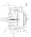
- a device for preparation 1is illustrated in section, which comprises a perforation system and injection 2 of a fluid under pressure, preferably cold or hot water, which is in the example shown switchable according to at least two positions of different injection depths inside a capsule 3.
- the deviceincludes a first lower subassembly in the form of a capsule holder 40 which has a shape and a size adapted to receive in part at least the capsule 3.
- the capsule 3may be a capsule closed, open or partially open.
- the capsulecomprises a closed chamber containing the substance to be extracted and / or dissolved and a holding portion such as membrane which opens, under the effect of the rise in pressure inside the chamber, in contact with engagement means such as relief elements 37.
- the engagement meanscan either be part of the capsule itself or be part of the capsule holder 40.
- the capsulemay also preferentially include means 31 for collecting the extracted liquid or the mixture and a means for 32, which has the advantage, in combination with the means of integrated openings, to deliver a product without direct contact with the device, in particular, with the capsule holder 40, which ensures an absence Cross-contamination of drinks, better hygiene, less cleaning and greater simplicity in the actual design of the preparation device.
- the capsulemay comprise a section 33, made of plastic or otherwise, to form or house the functional elements, namely the elements in relief, the sealed opening membrane 30 and the conduit means 32.
- the cup 33can be closed to form the chamber 34 by means of a second inlet membrane Sealed to sealing edges 36 of the capsule.
- the configuration of the capsulecan, of course, take many other concepts and / or forms without depart from the scope of the invention.
- the capsulecould, for example, include a body formed largely of flexible material (pouch) which fits into the device of equivalent way.
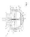
- Device 1comprises a second subset or system of perforation and injection 2 which cooperates in closing with the capsule holder 40 to define a housing to receive the capsule 3.
- the perforation system and 2comprises a central perforation and injection element having a channel for receiving a liquid under pressure, the piercing and injection element 5 being arranged to protrude into said housing and pierce the capsule 3 in at least one operating position of the device 1 to allow the introduction a liquid in the capsule 3 from the channel.
- the perforation system and injection 2is associated with an actuating means 6 integral with the element 5 of way to move it in the example shown in various wetting position to inside the capsule. For this, the piercing and injection element 5 passes to through a core 7 which is displaced in closure relative to the support of capsule 40.
- the head basemay be movable relative to a support 40 fixed or vice versa, or both can be mobile in closing.
- the actuating meansin the form of a bell-shaped mobile support called "mobile bell 6" in the rest of the description.
- the core 7is guided in translation relative to the mobile bell 6 at means of several guide tubes 70, 71 associated with return means (no represented), so that in the open position of the device the core 7 is applied substantially in the bottom of the mobile bell.
- the core 7further comprises peripheral sealing means 74 such as an elastomer seal arranged to press into closure against the edges peripherals 41 of the capsule holder 40.
- peripheral sealing means 74such as an elastomer seal arranged to press into closure against the edges peripherals 41 of the capsule holder 40.
- the core 7is therefore the part that applies as close as possible to the entrance surface of the capsule at the time of closure, which allows the introduction of the piercing and injection element central 5 through the capsule, more precisely, through the membrane input 35 of the capsule.
- An additional sealing element 75can also surround the piercing and injection element to prevent fluid from rising through the injection system and out of the device.
- the means for actuating the perforation element and injection or mobile bellis integral with the element 5 and allows, depending on its relative position with respect to the capsule holder, to change the position of the piercing and injection element in the capsule and therefore to change the wetting configuration of the substance contained in the closed chamber of the capsule.
- the mobile bell 6has detection means function of the same type of capsule that are formed by engagement edges 60 able to engage complementary edges 360 of the capsule and therefore, by therefore, which are able to push the bell 6 relative to the base of the head 7 according to the direction A according to the width of the edges of the capsule (as the shows Figure 2).
- the insertion position of the perforation and injection elementcan take two different positions, depending on whether the capsule has edges wide or edge extensions that engage the edges of the bell 6 or a narrow edge configuration, such that the edges of the bell do not meet no complementary edges of the capsule.
- the deviceis in a configuration in which the capsule has extensions or wide edges 36 to allow pushing the bell 6 and thus stop the piercing element and injection 3 in an insertion position close to the entrance of the capsule 3.
- such a positionmakes it possible to inject the fluid substantially at the level of the inlet of the bed of substance, which is well suited to ground products to extract, for example.
- Figure 2shows a configuration in which the capsule has narrower edges that pass the bell 6 along the capsule holder when closing the device without pushing it back.
- the perforation element and injection 5is allowed to reach a deeper position in the capsule 3.
- Such a positionis advantageous for wetting the substance by its base, thus causing a gradual disintegration of the mass of substance.
- such a mode of wettingis particularly effective.
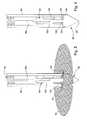
- FIG. 3shows in detail a preferred embodiment of the perforation and injection element 5 equipping the device of the invention.
- the perforation and injection element 5comprises a tubular body 80 defining a central passage or channel 80a for receiving a pressurized fluid symbolized by the arrow L coming from a feed in liquid, typically in hot water of a device (not shown).
- the proximal end 5acomprises an orifice 82 opening into the canal 80a and in which is fitted, in a sealed manner, a connector 84 to the water supply of the device.
- the distal end 5b of the element 5is arranged in the form of a flap comprising a movable shutter 86 arranged to close the channel 80a in its part distal, in a first rest position ( Figure 3 and Figure 4) and for in a second position said working position open under the effect of pressure liquid L against an elastic member 90 so as to release a distal orifice or passage 92 (FIG. 5) and create a layer of liquid 94 projected through the passage 92.
- the shutter 86has an end portion 86 of generally conical ending in a tip and a guide rear portion 96 sliding in the channel 80a of the tubular body 80.
- the pointed portion 88 of the shutter 86has as its function the perforation of the inlet membrane 35 of the capsule 3 when setting of the device, while the rear part 96 serves to guide the movement of the shutter in the tubular body 80.
- FIGS. 3 to 5also show that the tip portion of the shutter 86 includes an outer peripheral surface 98 which extends into the extension of the outer peripheral surface of the tubular body 80. This configuration makes it easier to extract the perforation element 5 from the capsule 3 and to avoid the risks of attachment of the shutter 86 on the cover 35 when of this extraction.
- the shutter 86further comprises, at the rear of its pointed end, a shoulder surface 100 which can bear against an annular surface 104 of complementary shape, formed at the distal end of the tubular body 80 when the shutter is in its rest position.
- the rear guide portion 96 of the shuttercomprises openings 102.
- the shutter 86is furthermore associated with the elastic element 90 extending in the channel 80a which remembers the shutter 86 in its rest position, position in which the shoulder surface 100 rests against the surface ring 104 to remove the passage 92 and close the channel 80a so waterproof.
- a sealmay be interposed between the shoulder surface 100 and the annular surface 104.
- resilient 90preferably comprises a coil spring of which a first rectilinear end extending along the longitudinal axis of the channel 80a is attached to the rear guide portion 96, for example by driving in the last, and a second end is fixed inside the tubular body.
- the second endhas the shape of a hook that is hooked on a pin 106 driven transversely into the tubular body at the orifice 82.
- the perforation and injection element 5is arranged substantially in the center of the housing receiving the capsule 3 and the openings 102 arranged in the rear guide portion 96 are arranged to produce a multidirectional divergent watering in the form of a liquid layer 94 continuously extending around the periphery of the tip of element 5. This configuration allows watering of the substance contained in capsule 3 of homogeneous and circular way.
- these two parameterscan be adjusted to obtain a layer of liquid having a desired thickness.
- these parameterswill be adjusted to obtain a liquid layer 94 less than 0.5 mm, typically 0.3 mm.
- the configuration of the openings 102 in the guiding rear portion 96to create a layer of shape liquid different, for example in the form of a circular sector, especially in the case where the piercing and injection element 5 is no longer disposed in the center of the housing receiving capsule 3 but on the periphery of it.
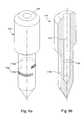
- FIGS. 6a and 6bshow an alternative embodiment of the element perforation and injection device, designated 110, which can be used in a device according to the invention.
- the element of perforation and injection 110comprises injection means 112 making it possible to produce a divergent jet in the form of a thin layer of liquid.
- These means 112include, in the illustrated example, two fixed slots 112a and 112b extending transversely to the longitudinal direction of the element 110 and communicating with the inlet channel of the liquid 114.
- fixed slotit will be understood a slot whose shape and dimensions do not vary over time. Both slots cover respectively a complementary angular sector to cover together a 360 degree area.
- the piercing and injection element 110thus produces a divergent jet extending over a circular sector wide enough to wet substantially all of the substance in the upper part of the capsule especially when it is arranged in the center of the capsule.
- the slots 112a and 112bare offset in height relative to each other. It goes without saying that the number and the form slots are not limited to the example described and that the skilled person can consider a number and shapes of different slots as long as this allows to obtain a jet covering the desired angular sector.
- the slots 112a and 112bare respectively arranged to that the thin layer of liquid is produced substantially continuously on a 360 degree angular sector.
- these slotsare arranged to produce a liquid layer having a thickness less than or equal to 0.5 mm and preferably less than 0.3mm.
- a height of the order of 0.5mmwe will choose preferably a height of the order of 0.5mm.
- the axis of the slits 112a and 112b defining the direction of the jet of liquidmakes an angle between 0 ° and 25 ° with the horizontal and preferably an angle of the order 15 °.
- the liquid injected by these orificesis thus directed upwards and first reflects against the lower surface of the lid 35 and is returned in a second time to the bed of substance being much more scattered. In doing so, homogeneity of wetting of the substance is improved.
- one or more slotswill be directed to the center of the capsule to produce a plurality of jets divergent areas that overlap to form a thin layer of liquid that sprinkles and wets the substance contained in the upper part the capsule on a sector angular between 120 and 360 ° and preferably of the order of 180 °.
Landscapes
- Engineering & Computer Science (AREA)
- Mechanical Engineering (AREA)
- Food Science & Technology (AREA)
- Apparatus For Making Beverages (AREA)
- General Preparation And Processing Of Foods (AREA)
- Non-Alcoholic Beverages (AREA)
- Containers And Packaging Bodies Having A Special Means To Remove Contents (AREA)
Abstract
Description
Translated fromFrenchLa présente invention concerne un dispositif pour la préparation d'uneboisson à partir d'une substance alimentaire telle qu'une substance à extraire et/ou àdissoudre contenue dans une capsule. Plus particulièrement, l'invention concerne untel dispositif comprenant un élément de perforation et d'injection perfectionné.L'invention se rapporte aussi à une méthode pour améliorer le mouillage ou ladissolution d'une substance contenue dans une capsule.The present invention relates to a device for the preparation of adrink from a food substance such as a substance to be extracted and / ordissolve contained in a capsule. More particularly, the invention relates to asuch a device comprising an improved perforation and injection element.The invention also relates to a method for improving the wetting ordissolution of a substance contained in a capsule.
L'utilisation de doses prédéterminées et préemballées sous forme de capsulecontenant une substance à extraire telle que du café moulu ou une substance àdissoudre telle que des produits chocolatés pour la préparation de boissons présentede nombreux avantages, entre autres ceux de faciliter les opérations de préparationde la boisson, d'assurer une préparation relativement propre et de contrôler undosage et une qualité relativement constantes de la boisson préparée.The use of predetermined and prepackaged doses in capsule formcontaining a substance to be extracted, such as ground coffee ordissolve such as chocolate products for the present beverage preparationmany advantages, among others those of facilitating preparatory operationsof the drink, to ensure a relatively clean preparation and to control arelatively constant dosage and quality of the prepared beverage.
Le principe d'extraction ou de dissolution de substances contenues dans lacapsule fermée consiste typiquement à enfermer la capsule dans une enceinte closed'un dispositif de préparation, percer une face de la capsule, injecter sous pressionune quantité d'eau chaude dans la capsule de façon à créer un environnement souspression à l'intérieur de la capsule pour soit extraire la substance, soit la dissoudre,puis libérer l'extrait de substance ou la substance dissoute à travers une faceopposée de la capsule, qui au contact de parties en saillie du dispositif s'ouvre sousl'effet de la pression interne.The principle of extraction or dissolution of substances contained in theclosed capsule typically consists of enclosing the capsule in a closed enclosureof a preparation device, pierce one face of the capsule, inject under pressurea quantity of hot water in the capsule so as to create an environment underpressure inside the capsule to either extract the substance or dissolve it,then release the substance extract or substance dissolved through a faceopposite of the capsule, which in contact with projecting parts of the device opens underthe effect of the internal pressure.
Des dispositifs permettant la mise en oeuvre de ce principe ont déjà étédécrits par exemple dans les brevets CH 605 293 et EP 242 556. Selon cesdocuments, le dispositif comprend un logement pour la capsule et un élément deperforation et d'injection réalisé sous la forme d'une pointe creuse comportant danssa région distale un ou plusieurs orifices d'injection de liquide. La pointe a unedouble fonction en ce qu'elle assure l'ouverture de la partie supérieure de la capsuled'une part, et qu'elle constitue le canal d'arrivée d'eau dans la capsule d'autre part. Ila également été envisagé pour améliorer l'extraction et/ou la dissolution de lasubstance contenue dans la capsule d'équiper ces dispositifs de plusieurs pointes assurant respectivement la double fonction susmentionnée comme cela est décritdans le document EP 1 203 554.Mechanisms for implementing this principle have already beendescribed for example in the patents CH 605 293 and EP 242 556. According to thesedocuments, the device includes a housing for the capsule and an element ofperforation and injection made in the form of a hollow tip comprising inits distal region one or more liquid injection orifices. The tip has adual function in that it ensures the opening of the upper part of the capsuleon the one hand, and that it constitutes the channel of arrival of water in the capsule on the other hand. hehas also been envisaged to improve the extraction and / or dissolution of thesubstance contained in the capsule to equip these devices with several tipsrespectively performing the aforementioned dual function as describedin
D'une part, un inconvénient de tels dispositifs provient du fait que les orificesd'injection de liquide de la pointe ont, compte tenu de leurs faibles dimensions,tendance à s'obstruer rapidement en raison du calcaire de l'eau ou du contact avecla substance notamment lorsque la capsule n'est pas immédiatement retirée del'appareil et que l'élément de perforation n'est pas rincé après usage, ce qui affecteles performances du dispositif. En particulier, la régularité du débit ainsi que lavitesse de jet diminuent au cours du temps; ce qui affecte les conditions d'extraction,la dissolution de la substance ainsi, par exemple, que la production de mousse.On the one hand, a disadvantage of such devices is that the orificesliquid injection tip have, considering their small dimensions,tendency to clog quickly due to limestone water or contact withthe substance in particular when the capsule is not immediately removed fromthe device and that the perforation element is not rinsed after use, which affectsthe performance of the device. In particular, the regularity of the flow and thejet speed decrease over time; which affects the extraction conditions,the dissolution of the substance as well, for example, as the production of foam.
Il serait donc utile d'avoir un dispositif qui résout ces problèmes.It would therefore be useful to have a device that solves these problems.
D'autre part, dans les dispositifs de l'art antérieur, la méthode de mouillageest basée sur la production d'un ou plusieurs jets discrets et dirigés dans unedirection préférentielle. Un seul jet discret et dirigé s'avère souvent insuffisant pourmouiller ou dissoudre une masse de substance contenue dans une capsule. De plus,un seul jet crée un chemin préférentiel et forme des trous dans la masse desubstance sans toutefois la mouiller ou la dissoudre entièrement. Il est donc communde faire appel à plusieurs jets dirigés chacun dans des directions différentes.Toutefois, une telle méthode de mouillage ou de dissolution n'est pas entièrementsatisfaisante car des chemins préférentiels subsistent.On the other hand, in the devices of the prior art, the method of wettingis based on the production of one or more discrete jets and directed into apreferential direction. A single discrete and directed jet is often insufficient forwet or dissolve a mass of substance contained in a capsule. Moreover,a single jet creates a preferential path and forms holes in the mass ofsubstance without, however, wetting or dissolving it entirely. It is therefore commonto use several jets each directed in different directions.However, such a method of wetting or dissolving is not entirelysatisfactory because preferential paths remain.
Il s'agit donc de prévoir une méthode qui mouille ou dissolve de manière plussatisfaisante la substance sans créer de chemins préférentiels mais tout enconservant la vitesse de jet nécessaire de façon à mouiller ou dissoudrecorrectement la substance et éventuellement, la faire mousser.It is therefore necessary to provide a method that wets or dissolves in a moresatisfactory substance without creating preferential paths but whilekeeping the necessary jet speed in order to wet or dissolveproperly the substance and possibly lather it.
L'invention a donc pour but principal de pallier les inconvénients de l'artantérieur susmentionné en fournissant un dispositif pour la préparation d'une boissonà partir d'une substance alimentaire telle qu'une substance à extraire et/ou àdissoudre contenue dans une capsule qui permette notamment d'éviter le risque deréduction de l'écoulement en raison d'obstructions du ou des orifices d'injection del'élément de perforation et d'injection formées par des dépôts calcaires ou desrésidus de substances.The main purpose of the invention is thus to overcome the disadvantages of the artaforementioned prior art by providing a device for the preparation of a drinkfrom a food substance such as a substance to be extracted and / ordissolve contained in a capsule which allows in particular to avoid the risk ofreduced flow due to obstructions of the injection port (s)the perforation and injection element formed by calcareous deposits orresidues of substances.
A cet effet , l'invention concerne un dispositif pour la préparation d'uneboisson à partir d'une substance alimentaire telle qu'une substance à extraire et/ou àdissoudre contenue dans une capsule, ledit dispositif comprenant un logement pourrecevoir la capsule, au moins un élément de perforation et d'injection ayant un canalpour recevoir un liquide sous pression, ledit élément de perforation et d'injection étant agencé pour faire saillie dans ledit logement et percer une face de la capsuledans au moins une position de fonctionnement du dispositif afin de permettrel'introduction d'un liquide à l'intérieur de ladite capsule à partir dudit canal, ledispositif étant caractérisé en ce que l'élément de perforation et d'injection présenteune extrémité distale agencée sous la forme d'un clapet ayant un obturateurprésentant une extrémité en forme de pointe, ledit clapet étant agencé pour obturerledit canal dans une première position, dite position de repos, et pour s'ouvrir sousl'effet de la pression du liquide à l'encontre d'un élément élastique de façon à libérerun passage en fonction de la pression et créer ainsi une couche de liquide projetée àtravers ledit passage dans une deuxième position, dite position de travail.For this purpose, the invention relates to a device for the preparation of adrink from a food substance such as a substance to be extracted and / ordissolve contained in a capsule, said device comprising a housing forreceiving the capsule, at least one piercing and injection element having a channelfor receiving a liquid under pressure, said piercing and injection elementbeing arranged to protrude into said housing and pierce a face of the capsulein at least one operating position of the device to enableintroducing a liquid inside said capsule from said channel, thecharacterized in that the perforation and injection element hasa distal end arranged in the form of a valve having a shutterhaving a tip-shaped end, said valve being arranged to closesaid channel in a first position, said rest position, and to open underthe effect of the pressure of the liquid against an elastic element so as to releasea passage depending on the pressure and thus create a layer of liquid projected tothrough said passage in a second position, said working position.
Une telle configuration de l'élément de perforation et d'injection a pouravantage d'être autonettoyant dans la mesure où en l'absence de pression du liquidele passage de circulation de celui-ci est fermé et ne s'ouvre qu'après la mise enpression du liquide dans le canal. Comme en l'absence de pression le passage estfermé par l'obturateur, on évite tout problème d'obstruction par le calcaire ou desrésidus de substance, même si la capsule n'a pas été retirée de l'appareilimmédiatement après usage.Such a configuration of the perforation and injection elementadvantage of being self-cleaning insofar as in the absence of liquid pressurethe circulation passage of this one is closed and opens only after thepressure of the liquid in the channel. As in the absence of pressure the passage isclosed by the shutter, one avoids any problem of obstruction by the limestone orsubstance residues, even if the capsule has not been removed from the deviceimmediately after use.
Selon un mode préféré de l'invention, l'élément de perforation et d'injectionest disposé sensiblement au centre du logement de la capsule et est agencé demanière à produire un arrosage divergent multidirectionnel sous la forme d'au moinsune couche de liquide. La fine couche s'étend avantageusement de manièrecontinue sur le pourtour de la pointe pour arroser la substance contenue dans lacapsule de manière sensiblement circulaire. Cette configuration particulière permetainsi de distribuer de façon simple une couche d'eau régulière sur un secteur de 360degrés.According to a preferred embodiment of the invention, the perforation and injection elementis arranged substantially in the center of the capsule housing and is arrangedway to produce multidirectional divergent watering in the form of at leasta layer of liquid. The thin layer advantageously extendscontinues around the edge of the tip to water the substance contained in thecapsule in a substantially circular manner. This particular configuration allowsthus to distribute in a simple way a regular layer of water on a sector of 360degrees.
De manière préférée, l'élément de perforation et d'injection comprend uncorps tubulaire définissant le canal. Ce corps tubulaire comporte un orifice proximaldestiné à être raccordé à une arrivée de liquide et un orifice distal définissant avecladite pointe ledit passage. L'orifice distal et l'orifice proximal sont reliés par leditcanal, et ledit obturateur présente une partie arrière de guidage coulissant dans leditcorps tubulaire tandis que l'extrémité en pointe comprend une surface périphériqueextérieure qui s'étend dans le prolongement de la surface périphérique extérieuredudit corps tubulaire.In a preferred manner, the perforation and injection element comprises atubular body defining the channel. This tubular body has a proximal orificeintended to be connected to a liquid inlet and a distal orifice defining withsaid tip said passage. The distal orifice and the proximal orifice are connected by saidchannel, and said shutter has a sliding guide rear portion in saidtubular body while the tip end includes a peripheral surfaceexterior extending in the extension of the outer peripheral surfacesaid tubular body.
Grâce à cette structure, l'obturateur peut être en appui contre le corpstubulaire de l'élément de perforation et d'injection au moment de la perforation desorte qu'il ne perturbe pas la perforation de l'opercule. De plus, l'obturateur ne risquepas de s'accrocher sur l'opercule lors du dégagement de l'élément de la capsule.Thanks to this structure, the shutter can be in support against the bodytubular element of the perforation and injection element at the time of perforation ofso that it does not disturb the perforation of the operculum. In addition, the shutter does not risknot to hang on the lid when disengaging the capsule element.
L'invention a aussi pour but de proposer une nouvelle méthode de mouillageet/ou de dissolution d'une substance contenue dans une capsule pour la productiond'une boisson consistant, au moyen d'un élément de perforation et d'injection, àpercer la capsule et injecter un liquide sous pression dans la capsule pour provoquerle mouillage et/ou la dissolution de la substance. L'élément est arrangé de manière àinjecter le liquide dans la capsule sous la forme d'au moins une fine couches'étendant de manière continue, divergente et multidirectionnelle couvrant unesurface d'arrosage selon un arc de cercle à l'intérieur de la capsule. Ainsi, une telleconfiguration d'arrosage a pour avantage de disperser le liquide sur une surfaceimportante, en conservant les avantages de puissance et de vitesse d'un jet maistout en évitant les inconvénients des jets discrets et dirigés qui créent des trous ouchemins préférentiels au travers de la substance. Lorsque de tels trous ou cheminspréférentiels sont créer, une partie de la substance n'est pas extraite ou dissoute; cequi cause une perte en matière solide et en arômes de la boisson et donc unemoindre qualité de celle-ci.The invention also aims to propose a new method of wettingand / or dissolving a substance contained in a capsule for productionof a consistent drink, by means of a piercing and injectionpierce the capsule and inject a liquid under pressure into the capsule to provokewetting and / or dissolution of the substance. The element is arranged in such a wayinject the liquid into the capsule in the form of at least a thin layerextending continuously, divergently and multidirectionally covering awatering surface according to an arc of a circle inside the capsule. So, such awatering configuration has the advantage of dispersing the liquid on a surfaceimportant, retaining the power and speed advantages of a jet butwhile avoiding the disadvantages of discrete and directed jets that create holes orpreferential paths through the substance. When such holes or pathspreferential are created, some of the substance is not extracted or dissolved; thiswhich causes a loss in solid matter and aromas of the drink and therefore alower quality of it.
De préférence, la fine couche couvre une surface d'arrosage comprise entre120 et 360 degrés dans la capsule. L'injection peut se faire à partir de l'axe centralde la capsule; dans ce cas il est préférable d'avoir une couche ou nappemultidirectionnelle circulaire s'étendant sur 360 degrés.Preferably, the thin layer covers a watering surface between120 and 360 degrees in the capsule. The injection can be done from the central axiscapsule; in this case it is better to have a layer or tableclothmultidirectional circular extending 360 degrees.
L'injection peut aussi être décalée par rapport à l'axe central; dans ce cas, ilest préférable d'avoir au moins deux couches d'arrosage, chacune d'elle arrosantselon un arc de 120 à 180 degrés. La couche d'arrosage est préférentiellementdirigée de manière transversale, relativement à la direction de sortie de la boissonhors de la capsule, de façon à arroser la plus large surface possible et permettreainsi ensuite l'écoulement du liquide injecté au travers de la masse. Ainsi, on assureun mouillage de toute la masse et moins de chemins préférentiels. En général, ladirection de sortie de la boisson correspond à l'axe de la capsule et donc à laverticale ou à une direction proche de la verticale. La direction de la couche ounappe pourrait aussi être légèrement inclinée par rapport à cette directiontransversale, vers le bas ou vers le haut, en particulier jusqu'à 30 degrés environ.The injection can also be shifted with respect to the central axis; in this case heis better to have at least two layers of watering, each of them wateringaccording to an arc of 120 to 180 degrees. The watering layer is preferentiallydirected transversely relative to the exit direction of the drinkout of the capsule, so as to water the widest possible area and allowand then the flow of the injected liquid through the mass. Thus, we ensurea wetting of the whole mass and fewer preferential paths. In general, theexit direction of the drink corresponds to the axis of the capsule and therefore to thevertical or at a direction close to the vertical. The direction of the layer ortablecloth could also be slightly inclined relative to this directioncrosswise, downward or upward, in particular up to about 30 degrees.
De préférence, la fine couche possède une épaisseur inférieure ou égale à0.5 mm, et de préférence inférieure à 0.3 mm. De telles épaisseurs garantissent quele liquide sorte sous forme d'un jet possédant suffisamment d'énergie cinétique pourdissoudre les substances solubles et vaincre la perte de charge produite lors dupassage du liquide à travers les substances à extraire pour atteindre les bords de lacapsule.Preferably, the thin layer has a thickness less than or equal to0.5 mm, and preferably less than 0.3 mm. Such thicknesses ensure thatthe liquid comes in the form of a jet having sufficient kinetic energy fordissolve the soluble substances and overcome the loss of pressure produced duringpassage of the liquid through the substances to be extracted to reach the edges of thecapsule.
La fine couche est obtenue par au moins une fente de l'élément deperforation ou d'injection; laquelle fente peut être fixe ou, au contraire, ouverte seulement au moment de l'injection en réponse à la pression du fluide. L'avantage del'ouverture de la fente sous l'effet de la pression du fluide est son caractère autonettoyantqui garantit une reproductibilité du mouillage et/ou de la dissolution de lasubstance cycle après cycle. Toutefois, une nappe fixe est de conception plus simpleet plus économique.The thin layer is obtained by at least one slit of the element ofperforation or injection; which slot can be fixed or, conversely, openonly at the time of injection in response to fluid pressure. The advantage ofthe opening of the slot under the effect of the pressure of the fluid is its self-cleaning characterwhich guarantees reproducibility of the wetting and / or dissolution of thesubstance cycle after cycle. However, a fixed sheet is of simpler designand more economical.
D'autres caractéristiques et avantages de l'invention apparaítront à la lecturede la description d'un exemple de réalisation, donné à titre illustratif et non limitatif,en référence aux dessins annexés dans lesquels:
- les figures 1 et 2 sont des vues en coupe d'un dispositif pour lapréparation d'une boisson selon un mode préféré, le dispositif étant représenté dansdeux modes de fonctionnement différents;
- la figure 3 est une vue en coupe de l'élément de perforation etd'injection du dispositif selon l'invention;
- les figures 4 et 5 sont des vues en perspective et en coupe partielled'un détail de l'élément de perforation respectivement en position de repos et enposition de travail.;
- les figures 6a et 6b sont des vues schématiques respectivement enperspective et en perspective coupée d'une variante de réalisation de l'élément deperforation et d'injection utilisable dans le dispositif de l'invention.
- Figures 1 and 2 are sectional views of a device for the preparation of a beverage according to a preferred embodiment, the device being shown in two different modes of operation;
- Figure 3 is a sectional view of the perforation and injection element of the device according to the invention;
- Figures 4 and 5 are views in perspective and in partial section of a detail of the perforation element respectively in the rest position and in the working position;
- FIGS. 6a and 6b are diagrammatic views respectively in perspective and in broken perspective of an alternative embodiment of the perforation and injection element that can be used in the device of the invention.
En référence aux figures 1 et 2, un mode de réalisation d'un dispositif depréparation 1 est illustré en coupe, qui comprend un système de perforation etd'injection 2 d'un fluide sous pression, de préférence de l'eau froide ou chaude, quiest dans l'exemple représenté commutable selon au moins deux positions deprofondeur d'injection différentes à l'intérieur d'une capsule 3. Le dispositif comprendun premier sous-ensemble inférieur sous forme d'un support de capsule 40 lequel aune forme et une taille adaptées à recevoir en partie au moins la capsule 3. Lacapsule 3 peut être une capsule fermée, ouverte ou partiellement ouverte.With reference to FIGS. 1 and 2, an embodiment of a device for
Selon un mode préféré, la capsule comprend une chambre fermée contenantla substance à extraire et/ou à dissoudre et une portion de retenue telle qu'unemembrane 30 laquelle s'ouvre, sous l'effet de la montée en pression à l'intérieur de lachambre, au contact de moyens d'engagement tels que des éléments en reliefs 37.Les moyens d'engagement peuvent soit faire partie de la capsule elle-même, soitfaire partie du support de capsule 40. La capsule peut aussi préférentiellementcomprendre des moyens de collecte 31 du liquide extrait ou du mélange et un moyende conduit 32 qui lui sont propres, ce qui a pour avantage, en combinaison avec les moyens d'ouvertures intégrés, de délivrer un produit sans contact direct avec ledispositif, en particulier, avec le support de capsule 40, ce qui assure une absencede contamination croisée des boissons, une meilleure hygiène, moins de nettoyageet une plus grande simplicité dans la conception même du dispositif de préparation.Plus précisément, la capsule peut comprendre une coupe 33, en plastique ou autre,pour former ou loger les éléments fonctionnels, à savoir les éléments en reliefs, lamembrane d'ouverture scellée 30 et les moyens de conduit 32. La coupe 33 peutêtre fermée pour former la chambre 34 au moyen d'une seconde membrane d'entrée35 scellée sur des bords de scellage 36 de la capsule. La configuration de la capsulepeut, bien entendu, prendre bien d'autres concepts et/ou formes sans pour autantsortir du cadre de l'invention. La capsule pourrait, par exemple, comprendre un corpsformé en grande partie en matière souple (sachet) qui s'insère dans le dispositif defaçon équivalente.In a preferred embodiment, the capsule comprises a closed chamber containingthe substance to be extracted and / or dissolved and a holding portion such asmembrane which opens, under the effect of the rise in pressure inside thechamber, in contact with engagement means such as
Une capsule préférée est décrite plus en détails dans la demande de brevetEuro-PCT No. 03/00384 déposée le 13 janvier 2003, dont le contenu en entier estincorporé ici par référence.A preferred capsule is described in more detail in the patent applicationEuro-PCT No. 03/00384 filed on 13 January 2003, the entire contents of which areincorporated herein by reference.
Le dispositif 1 comprend un second sous-ensemble ou système deperforation et d'injection 2 qui coopère en fermeture avec le support de capsule 40pour définir un logement pour recevoir la capsule 3. Le système de perforation etd'injection 2 comprend un élément de perforation et d'injection 5 central ayant uncanal pour recevoir un liquide sous pression, l'élément de perforation et d'injection 5étant agencé pour faire saillie dans ledit logement et percer la capsule 3 dans aumoins une position de fonctionnement du dispositif 1 afin de permettre l'introductiond'un liquide dans la capsule 3 à partir du canal. Le système de perforation etd'injection 2 est associé à un moyen d'actionnement 6 solidaire de l'élément 5 demanière à le déplacer dans l'exemple illustré dans divers position de mouillage àl'intérieur de la capsule. Pour cela, l'élément de perforation et d'injection 5 passe autravers d'un noyau 7 lequel est déplacé en fermeture relativement au support decapsule 40. Il est entendu que la base de tête peut être mobile relativement à unsupport 40 fixe ou inversement, ou encore, les deux peuvent être mobiles enfermeture. Sur le noyau 7 est monté le moyen d'actionnement sous forme d'unsupport mobile en forme de cloche appelé "cloche mobile 6" dans la suite de ladescription. Le noyau 7 est guidé en translation par rapport à la cloche mobile 6 aumoyen de plusieurs tubes de guidage 70, 71 associés à des moyens de rappel (nonreprésentés), de sorte qu'en position d'ouverture du dispositif le noyau 7 soitappliqué sensiblement dans le fond de la cloche mobile.
Le noyau 7 comprend, en outre, des moyens d'étanchéité périphériques 74tels qu'un joint élastomère agencé pour s'appuyer en fermeture contre les bordspériphériques 41 du support de capsule 40. Le noyau 7 est donc la partie quis'applique au plus près de la surface d'entrée de la capsule au moment de lafermeture, ce qui permet l'introduction de l'élément de perforation et d'injectioncentral 5 au travers de la capsule, plus précisément, au travers de la membraned'entrée 35 de la capsule. Un élément d'étanchéité supplémentaire 75 peut aussientourer l'élément de perforation et d'injection pour éviter une remontée de fluide autravers du système d'injection et en dehors du dispositif.The
Dans l'exemple illustré, le moyen d'actionnement de l'élément de perforationet d'injection ou cloche mobile est solidaire de l'élément 5 et permet, en fonction desa position relative par rapport au support de capsule, de modifier la position del'élément de perforation et d'injection dans la capsule et donc de changer laconfiguration de mouillage de la substance contenue dans la chambre fermée de lacapsule. Plus précisément, la cloche mobile 6 possède des moyens de détection enfonction du type même de capsule qui sont formés par des bords d'engagement 60aptes à engager des bords complémentaires 360 de la capsule et donc, parconséquent, qui sont aptes à repousser la cloche 6 par rapport à la base de tête 7selon la direction A en fonction de la largeur des bords de la capsule (comme lemontre la figure 2). La position d'introduction de l'élément de perforation et d'injectionpeut donc prendre deux positions distinctes, selon que la capsule possède des bordslarges ou extensions de bords qui s'engagent à l'encontre des bords de la cloche 6ou une configuration de bords étroite, telle que les bords de la cloche ne rencontrentpas de bords complémentaires de la capsule. A la figure 1, le dispositif est dans uneconfiguration dans laquelle la capsule possède des extensions ou bords larges 36pour permettre de repousser la cloche 6 et donc d'arrêter l'élément de perforation etd'injection 3 dans une position d'introduction proche de l'entrée de la capsule 3. Unetelle position permet d'injecter le fluide sensiblement au niveau de l'entrée du lit desubstance, ce qui convient bien aux produits moulus à extraire, par exemple.In the example illustrated, the means for actuating the perforation elementand injection or mobile bell is integral with the
La figure 2 montre une configuration dans laquelle la capsule possède desbords plus étroits qui laissent passer la cloche 6 le long du support de capsule lorsde la fermeture du dispositif sans la repousser. Dans ce cas, l'élément de perforationet d'injection 5 est autorisé à atteindre une position plus profonde dans la capsule 3.Une telle position s'avère avantageuse pour mouiller la substance par sa base,entraínant ainsi une désagrégation progressive de la masse de substance. Pour lessubstances solubles, par exemple, un tel mode de mouillage s'avère particulièrementefficace.Figure 2 shows a configuration in which the capsule hasnarrower edges that pass the
Les figures 3 à 5 montrent en détail un mode de réalisation préféré del'élément de perforation et d'injection 5 équipant le dispositif de l'invention. On voitnotamment à la figure 3 que l'élément de perforation et d'injection 5 comprend uncorps tubulaire 80 définissant un passage central ou canal 80a pour recevoir unliquide sous pression symbolisé par la flèche L provenant d'une alimentation enliquide, typiquement en eau chaude d'un dispositif (non représenté).Figures 3 to 5 show in detail a preferred embodiment ofthe perforation and
L'extrémité proximale 5a comprend un orifice 82 débouchant dans le canal80a et dans lequel est emmanché, de manière étanche, un embout de connexion 84à l'alimentation en eau du dispositif.The
L'extrémité distale 5b de l'élément 5 est agencée sous la forme d'un clapetcomprenant un obturateur 86 mobile agencé pour obturer le canal 80a dans sa partiedistale, dans une première position dite position de repos (figure 3 et figure 4) et pourdans une deuxième positon dite position de travail s'ouvrir sous l'effet de la pressiondu liquide L à l'encontre d'un élément élastique 90 de façon à libérer un orifice distalou passage 92 (figure 5) et créer une couche de liquide 94 projetée à travers lepassage 92.The
L'obturateur 86 présente une partie extrême 86 de forme généralementconique se terminant en pointe et une partie arrière de guidage 96 coulissant dans lecanal 80a du corps tubulaire 80. La portion en pointe 88 de l'obturateur 86 a pourfonction la perforation de la membrane d'entrée 35 de la capsule 3 lors de la mise enoeuvre du dispositif, tandis que la partie arrière 96 à pour fonction de guider lemouvement de l'obturateur dans le corps tubulaire 80.The
On voit également aux figures 3 à 5 que la portion en pointe de l'obturateur86 comprend une surface périphérique extérieure 98 qui s'étend dans leprolongement de la surface périphérique extérieure du corps tubulaire 80. Cetteconfiguration permet de faciliter l'extraction de l'élément de perforation 5 de lacapsule 3 et d'éviter les risques d'accrochage de l'obturateur 86 sur l'opercule 35 lorsde cette extraction.FIGS. 3 to 5 also show that the tip portion of the
L'obturateur 86 comprend en outre, à l'arrière de son extrémité en pointe, unesurface d 'épaulement 100 qui peut s'appuyer contre une surface annulaire 104 deforme complémentaire, ménagée à l'extrémité distale du corps tubulaire 80 lorsquel'obturateur est dans sa position de repos.The
Afin que le liquide puisse circuler depuis l'orifice proximal vers la surfaced'épaulement 100 et s'écouler dans la capsule à travers le passage 92 lorsquel'obturateur 86 est dans sa position de travail, la partie arrière de guidage 96 del'obturateur comprend des ouvertures 102.So that the liquid can flow from the proximal orifice to the
L'obturateur 86 est par ailleurs associé à l'élément élastique 90 s'étendantdans le canal 80a qui permet de rappeler l'obturateur 86 dans sa position de repos,position dans laquelle la surface d'épaulement 100 s'appuie contre la surfaceannulaire 104 pour supprimer le passage 92 et obturer le canal 80a de façonétanche. Selon une variante non représentée, un joint d'étanchéité peut êtreinterposé entre la surface d'épaulement 100 et la surface annulaire 104. L'organeélastique 90 comprend de préférence un ressort hélicoïdal dont une premièreextrémité rectiligne s'étendant selon l'axe longitudinal du canal 80a est fixée à lapartie arrière de guidage 96, par exemple par chassage dans celle dernière, et unedeuxième extrémité est fixée à l'intérieur du corps tubulaire. Dans l'exemple illustré,la deuxième extrémité présente la forme d'un crochet qui est accroché sur unegoupille 106 chassée transversalement dans le corps tubulaire au niveau de l'orifice82.The
Dans l'exemple illustré, l'élément de perforation et d'injection 5 est disposésensiblement au centre du logement recevant la capsule 3 et les ouvertures 102ménagées dans la partie arrière de guidage 96 sont agencées pour produire unarrosage divergeant multidirectionnel sous la forme d'une couche de liquide 94s'étendant de manière continue sur le pourtour de la pointe de l'élément 5. Cetteconfiguration permet un arrosage de la substance contenue dans la capsule 3 demanière homogène et circulaire.In the example shown, the perforation and
Comme la dimension de l'ouverture du passage 92 est fonction à la fois de lapression d'injection du liquide L dans l'élément 5 et de la force de rappel de l'élémentélastique 90, ces deux paramètres peuvent être ajustés pour obtenir une couche deliquide ayant une épaisseur désirée. De préférence, ces paramètres seront ajustéspour obtenir une couche de liquide 94 inférieure à 0,5mm, typiquement de 0,3mm.As the size of the opening of the
On peut également envisager en variante de configurer les ouvertures 102dans la partie arrière de guidage 96 afin de créer une couche de liquide de formedifférente, par exemple en forme de secteur circulaire, notamment dans le cas oùl'élément de perforation et d'injection 5 n'est plus disposé au centre du logementrecevant la capsule 3 mais à la périphérie de celui-ci.It is also possible to envisage as an alternative the configuration of the
Aux figures 6a et 6b on a représenté une variante de réalisation de l'élémentde perforation et d'injection, désignée par la référence 110 utilisable dans undispositif selon l'invention. Comme cela ressort de ces figures, l'élément deperforation et d'injection 110 comprend des moyens d'injection 112 permettant deproduire un jet divergent sous la forme d'une fine couche de liquide. Ces moyens112 comprennent, dans l'exemple illustré deux fentes fixes 112a et 112b s'étendant transversalement à la direction longitudinale de l'élément 110 et communiquant avecle canal d'arrivée du liquide 114. Par fente fixe on comprendra une fente dont laforme et les dimensions ne varient pas au cours du temps. Les deux fentes couvrentrespectivement un secteur angulaire complémentaire pour couvrir ensemble unsecteur de 360 degrés. L'élément de perforation et d'injection 110 produit ainsi unejet divergent s'étendant sur un secteur circulaire suffisamment large pour mouillersensiblement la totalité de la substance se trouvant dans la partie supérieure de lacapsule notamment lorsqu'il est disposé au centre de la capsule. Pour des raisonsliées à la fabrication de l'élément 110, on notera que les fentes 112a et 112b sontdécalées en hauteur l'une par rapport à l'autre. Il va de soi que le nombre et la formedes fentes ne sont pas limités à l'exemple décrit et que l'homme de métier pourraenvisager un nombre et des formes de fentes différents dès lors que cela permetd'obtenir un jet couvrant le secteur angulaire désiré.FIGS. 6a and 6b show an alternative embodiment of the elementperforation and injection device, designated 110, which can be used in adevice according to the invention. As can be seen from these figures, the element ofperforation and
On notera que les fentes 112a et 112b sont respectivement agencées pourque la fine couche de liquide soit produite de manière sensiblement continue sur unsecteur angulaire de 360 degrés. En outre, ces fentes sont agencées pour produireune couche de liquide ayant une épaisseur inférieure ou égale à 0,5mm et depréférence inférieure à 0,3mm. A cet effet, pour chacune des fentes on choisira depréférence une hauteur de l'ordre de 0.5mm.It will be noted that the
Selon une variante avantageuse non représentée de cette variante deréalisation, l'axe des fentes 112a et 112b définissant la direction du jet de liquide, faitun angle compris entre 0° et 25° avec l'horizontale et de préférence un angle del'ordre 15°. Le liquide injecté par ces orifices est ainsi dirigé vers le haut et seréfléchit dans un premier temps contre la surface inférieure de l'opercule 35 et estrenvoyé dans un second temps vers le lit de substance en étant beaucoup plusdispersé. Ce faisant, l'homogénéité du mouillage de la substance est améliorée.According to an advantageous variant, not shown, of this variant ofembodiment, the axis of the
Bien entendu on peut aussi envisager de disposer l'élément de perforation etd'injection 110 de manière excentrée à l'intérieur de la capsule, et plus précisémentau voisinage de la paroi latérale de celle-ci. Dans ce cas, une ou plusieurs fentesseront dirigées vers le centre de la capsule pour produire une pluralité de jetsdivergents qui se recouvrent pour former une fine couche de liquide qui arrose etmouille la substance contenue dans la partie supérieure la capsule sur un secteurangulaire compris entre 120 et 360° et de préférence de l'ordre de 180°.Of course we can also consider having the perforation element and110 of injection in an eccentric manner inside the capsule, and more preciselyin the vicinity of the side wall thereof. In this case, one or more slotswill be directed to the center of the capsule to produce a plurality of jetsdivergent areas that overlap to form a thin layer of liquid that sprinkles andwets the substance contained in the upper part the capsule on a sectorangular between 120 and 360 ° and preferably of the order of 180 °.
L'invention n'est bien entendu pas limitée au mode de réalisation décrit ci-dessuset on comprendra que diverses modifications et/ou améliorations évidentespour l'homme de métier pourront y être apportées sans sortir du cadre de l'inventiondéfinie par les revendications annexées.The invention is of course not limited to the embodiment described aboveand it will be understood that various modifications and / or obvious improvementsfor the skilled person can be made without departing from the scope of the inventiondefined by the appended claims.
Claims (19)
Translated fromFrenchcaractérisée en ce que:
characterized in that
Priority Applications (20)
| Application Number | Priority Date | Filing Date | Title |
|---|---|---|---|
| EP03019162AEP1510158A1 (en) | 2003-08-25 | 2003-08-25 | Apparatus and method for the preparation of a beverage from an ingredient contained in a cartridge |
| CA2536672ACA2536672C (en) | 2003-08-25 | 2004-08-13 | Device and method for preparing a drink from a food substance contained in a capsule |
| CNB2004800242876ACN100560005C (en) | 2003-08-25 | 2004-08-13 | Device and method for preparing a beverage from a food substance contained in a capsule |
| PT04764120TPT1659910E (en) | 2003-08-25 | 2004-08-13 | Device and method for preparing a drink from a food substance contained in a capsule |
| DE602004027053TDE602004027053D1 (en) | 2003-08-25 | 2004-08-13 | DEVICE AND METHOD FOR PREPARING A BEVERAGE FROM INGREDIENTS IN A CARTRIDGE |
| HK07102570.7AHK1096273B (en) | 2003-08-25 | 2004-08-13 | Device and method for preparing a drink from a food substance contained in a capsule |
| SI200431457TSI1659910T1 (en) | 2003-08-25 | 2004-08-13 | Device and method for preparing a drink from a food substance contained in a capsule |
| EP04764120AEP1659910B1 (en) | 2003-08-25 | 2004-08-13 | Device and method for preparing a drink from a food substance contained in a capsule |
| AT04764120TATE466508T1 (en) | 2003-08-25 | 2004-08-13 | DEVICE AND METHOD FOR PREPARING A DRINK FROM AN INGREDIENT CONTAINED IN A CARTRIDGE |
| JP2006524281AJP4658935B2 (en) | 2003-08-25 | 2004-08-13 | Apparatus and method for making a beverage from food material contained in a capsule |
| AU2004267932AAU2004267932B2 (en) | 2003-08-25 | 2004-08-13 | Device and method for preparing a drink from a food substance contained in a capsule |
| CN2008101690193ACN101380199B (en) | 2003-08-25 | 2004-08-13 | Device and method for preparing a drink from a food substance contained in a capsule |
| ES04764120TES2344952T3 (en) | 2003-08-25 | 2004-08-13 | DEVICE AND METHOD FOR THE PREPARATION OF A DRINK FROM A FOOD SUBSTANCE CONTAINED IN A CAPSULE. |
| PL04764120TPL1659910T3 (en) | 2003-08-25 | 2004-08-13 | Device and method for preparing a drink from a food substance contained in a capsule |
| US10/569,515US7854192B2 (en) | 2003-08-25 | 2004-08-13 | Device and method for preparing a drink from a food substance contained in a capsule |
| TW093124417ATWI335808B (en) | 2003-08-25 | 2004-08-13 | Device for preparing a beverage from a food substance contained in a capsule |
| PCT/EP2004/009126WO2005020770A2 (en) | 2003-08-25 | 2004-08-13 | Device and method for preparing a drink from a food substance contained in a capsule |
| MYPI20043357AMY146428A (en) | 2003-08-25 | 2004-08-18 | Device and method for preparing a beverage from a food substance contained in a capsule |
| ARP040103038AAR045488A1 (en) | 2003-08-25 | 2004-08-24 | DEVICE AND METHOD FOR THE PREPARATION OF A DRINK FROM A FOOD SUBSTANCE CONTAINED IN A CAPSULE |
| US12/897,443US20110052773A1 (en) | 2003-08-25 | 2010-10-04 | Device and method for preparing a drink from a food substance contained in a capsule |
Applications Claiming Priority (1)
| Application Number | Priority Date | Filing Date | Title |
|---|---|---|---|
| EP03019162AEP1510158A1 (en) | 2003-08-25 | 2003-08-25 | Apparatus and method for the preparation of a beverage from an ingredient contained in a cartridge |
Publications (1)
| Publication Number | Publication Date |
|---|---|
| EP1510158A1true EP1510158A1 (en) | 2005-03-02 |
Family
ID=34089597
Family Applications (2)
| Application Number | Title | Priority Date | Filing Date |
|---|---|---|---|
| EP03019162AWithdrawnEP1510158A1 (en) | 2003-08-25 | 2003-08-25 | Apparatus and method for the preparation of a beverage from an ingredient contained in a cartridge |
| EP04764120AExpired - LifetimeEP1659910B1 (en) | 2003-08-25 | 2004-08-13 | Device and method for preparing a drink from a food substance contained in a capsule |
Family Applications After (1)
| Application Number | Title | Priority Date | Filing Date |
|---|---|---|---|
| EP04764120AExpired - LifetimeEP1659910B1 (en) | 2003-08-25 | 2004-08-13 | Device and method for preparing a drink from a food substance contained in a capsule |
Country Status (16)
| Country | Link |
|---|---|
| US (2) | US7854192B2 (en) |
| EP (2) | EP1510158A1 (en) |
| JP (1) | JP4658935B2 (en) |
| CN (2) | CN100560005C (en) |
| AR (1) | AR045488A1 (en) |
| AT (1) | ATE466508T1 (en) |
| AU (1) | AU2004267932B2 (en) |
| CA (1) | CA2536672C (en) |
| DE (1) | DE602004027053D1 (en) |
| ES (1) | ES2344952T3 (en) |
| MY (1) | MY146428A (en) |
| PL (1) | PL1659910T3 (en) |
| PT (1) | PT1659910E (en) |
| SI (1) | SI1659910T1 (en) |
| TW (1) | TWI335808B (en) |
| WO (1) | WO2005020770A2 (en) |
Cited By (3)
| Publication number | Priority date | Publication date | Assignee | Title |
|---|---|---|---|---|
| WO2008130221A1 (en)* | 2007-04-24 | 2008-10-30 | N.V. Nutricia | A device and a method for preparing a ready to use liquid product |
| EP2080454A1 (en) | 2008-01-18 | 2009-07-22 | Nestec S.A. | Beverage machine and piercing member for an opening device of a beverage machine |
| CN110662465A (en)* | 2017-03-28 | 2020-01-07 | 创新工艺有限公司 | Device for preparing leaching liquor |
Families Citing this family (45)
| Publication number | Priority date | Publication date | Assignee | Title |
|---|---|---|---|---|
| EP1975087B2 (en)* | 2007-03-19 | 2018-05-16 | Nestec S.A. | Capsule with flow regulating technology |
| US10722066B2 (en)* | 2010-12-04 | 2020-07-28 | Adrian Rivera | Windowed single serving brewing material holder |
| US11832755B2 (en)* | 2007-07-13 | 2023-12-05 | Adrian Rivera | Brewing material container for a beverage brewer |
| ITMO20070323A1 (en)* | 2007-10-22 | 2009-04-23 | Illycaffe Spa | CONTAINER |
| US8746505B2 (en)* | 2007-10-29 | 2014-06-10 | S.C. Johnson & Son, Inc. | Multi-sensory product combining reeds, volatile actives diffusion, form-within-a-form construction, and light show capabilities |
| USD602396S1 (en) | 2008-07-09 | 2009-10-20 | S.C. Johnson & Son, Inc. | Tall vase |
| GB2469873B (en)* | 2009-05-01 | 2011-09-07 | Kraft Foods R & D Inc | Beverage preparation machines |
| DE102009026830A1 (en)* | 2009-06-08 | 2010-12-16 | Kraft Foods R & D, Inc., Northfield | Brewing head of a hot beverage vending machine based on dimensionally stable beverage cartridges |
| CN105193269B (en)* | 2009-06-17 | 2019-04-19 | 皇家戴维艾格伯茨有限公司 | It is used to prepare system, packing and the method for beverage |
| WO2010137959A1 (en)* | 2009-06-17 | 2010-12-02 | Sara Lee/De N.V. | System and method for preparing a predetermined quantity of beverage |
| RU2012128493A (en)* | 2009-12-08 | 2014-01-20 | Нестек С.А. | SYSTEM, SET OF CAPSULES AND METHOD FOR PREPARING A DRINK BY CENTRIFUGING |
| DK2404844T3 (en)* | 2010-07-07 | 2012-10-15 | Nestec Sa | Capsule for preparing a food product from a food preparation machine |
| US10071851B2 (en) | 2010-07-12 | 2018-09-11 | Robert Bao Vu | Apparatus and products for producing beverages, and methods for making and using same |
| SMT201900157T1 (en)* | 2010-07-22 | 2019-05-10 | K Fee System Gmbh | Portion capsule having an identifier |
| GB201110848D0 (en)* | 2011-06-24 | 2011-08-10 | Mars Inc | Beverage preparation apparatus and method and beverage capsules for use therein |
| RU2014111180A (en) | 2011-08-25 | 2015-09-27 | Нестек С.А. | CARTRIDGE PUNCH PUNCH WITH LONG SERVICE LIFE |
| US9428328B2 (en) | 2011-09-01 | 2016-08-30 | 2266170 Ontario Inc. | Beverage capsule |
| US20150150409A1 (en) | 2012-07-06 | 2015-06-04 | Conopco, Inc., D/B/A/ Unilever | Capsule recognition system |
| JP2015534486A (en)* | 2012-10-09 | 2015-12-03 | ネステク ソシエテ アノニム | Beverage machine equipped with ingredient capsule attachment device |
| EP2730523B1 (en) | 2012-11-12 | 2016-04-06 | 2266170 Ontario, Inc. | Beverage capsule and process and system for making same |
| WO2014146952A1 (en) | 2013-03-21 | 2014-09-25 | Unilever Plc | Method, device and capsule for brewing a beverage |
| CA2905217C (en) | 2013-04-03 | 2016-11-08 | 2266170 Ontario Inc. | Capsule machine and components |
| US10154752B2 (en) | 2013-05-23 | 2018-12-18 | 2266170 Ontario Inc. | Capsule housing |
| US10611507B2 (en) | 2013-08-20 | 2020-04-07 | 2266170 Ontario Inc. | Capsule with control member |
| ITMO20130295A1 (en)* | 2013-10-17 | 2015-04-18 | Sarong Spa | DRINKING MACHINE FOR DRINKS |
| US10314319B2 (en)* | 2013-11-20 | 2019-06-11 | 2266170 Ontario Inc. | Method and apparatus for accelerated or controlled degassing of roasted coffee |
| CN105813519B (en)* | 2013-12-20 | 2019-12-20 | 皇家飞利浦有限公司 | Consumable set and beverage dispenser |
| US20170172338A1 (en)* | 2014-02-14 | 2017-06-22 | Remington Designs, Llc | Beverage brewer and related methods for brewing beverages |
| TWI511697B (en)* | 2014-02-21 | 2015-12-11 | Pegatron Corp | Drink maker |
| JP6618919B2 (en) | 2014-03-07 | 2019-12-11 | ソシエテ・デ・プロデュイ・ネスレ・エス・アー | Packs and machines for preparing beverages |
| US10336531B2 (en) | 2014-03-21 | 2019-07-02 | 2266170 Ontario Inc. | Capsule with steeping chamber |
| JP6243090B1 (en)* | 2014-12-04 | 2017-12-06 | 九▲陽▼股▲フン▼有限公司 | Horizontal rotary beverage preparation machine and beverage preparation method thereof |
| ITUB20155389A1 (en)* | 2015-11-09 | 2017-05-09 | Sarong Spa | CAPPULE FOR BEVERAGES |
| CA3041722A1 (en) | 2016-11-09 | 2018-05-17 | Pepsico, Inc. | Carbonated beverage makers, methods, and systems |
| CN109588990B (en)* | 2017-09-30 | 2021-08-10 | 广东美的生活电器制造有限公司 | Beverage capsule |
| KR102071046B1 (en)* | 2018-02-05 | 2020-01-28 | 주식회사 이노디자인 | Dripper and portable coffee drinking tumbler |
| US11235920B2 (en) | 2018-06-08 | 2022-02-01 | Pepsico, Inc. | Beverage ingredient pod |
| IT201900012381A1 (en)* | 2019-07-19 | 2021-01-19 | Lavazza Luigi Spa | SYSTEM, MACHINE AND CONTAINER FOR THE PREPARATION OF FLUID FOOD PRODUCTS |
| IT201900012396A1 (en)* | 2019-07-19 | 2021-01-19 | Lavazza Luigi Spa | CONTAINER, SYSTEM AND METHOD FOR THE PREPARATION OF FLUID FOOD PRODUCTS |
| US11805934B1 (en)* | 2020-10-21 | 2023-11-07 | Adrian Rivera | Brewing material lid and container for a beverage brewer |
| US12171361B2 (en) | 2020-12-30 | 2024-12-24 | Sharkninja Operating Llc | Hybrid receptacle beverage brewing system |
| CN115479458B (en)* | 2022-09-30 | 2024-01-26 | 湖北中烟工业有限责任公司 | Drying device |
| USD1048792S1 (en) | 2023-04-12 | 2024-10-29 | Sharkninja Operating Llc | Coffee machine |
| USD1048793S1 (en) | 2023-05-02 | 2024-10-29 | Sharkninja Operating Llc | Coffee machine |
| CN116491811B (en)* | 2023-05-17 | 2025-09-05 | 漳州松霖智能家居有限公司 | Water outlet device and beverage preparation machine |
Citations (6)
| Publication number | Priority date | Publication date | Assignee | Title |
|---|---|---|---|---|
| US2589783A (en)* | 1948-04-09 | 1952-03-18 | Cory Corp | Beverage brewer |
| DE7430109U (en)* | 1974-09-06 | 1976-03-18 | Bosch-Siemens Hausgeraete Gmbh, 7000 Stuttgart | Electric coffee maker |
| CH605293A5 (en) | 1976-12-17 | 1978-09-29 | Nestle Sa | |
| EP0242556A1 (en) | 1986-04-24 | 1987-10-28 | Societe Des Produits Nestle S.A. | Beverage-extracting device for cartridges |
| EP1203554A1 (en) | 2000-11-03 | 2002-05-08 | Societe Des Produits Nestle S.A. | Device for extracting food material stored in a reloading cartridge |
| EP1295554A1 (en)* | 2001-09-21 | 2003-03-26 | SGL Italia S.r.l. | Coffee machine for brewing coffee from ground coffee packed in a cartridge |
Family Cites Families (12)
| Publication number | Priority date | Publication date | Assignee | Title |
|---|---|---|---|---|
| US2141684A (en)* | 1938-04-05 | 1938-12-27 | Joseph A Diemer | Dispensing device |
| US2206838A (en)* | 1940-04-15 | 1940-07-02 | Connecticut Paper Products Inc | Dispensing |
| US2587783A (en)* | 1950-07-27 | 1952-03-04 | Celanese Corp | Starter handle |
| US5547572A (en)* | 1985-05-14 | 1996-08-20 | Parker Hannifin Corporation | Fuel Filter |
| JPH0614706Y2 (en)* | 1986-12-24 | 1994-04-20 | 松下電器産業株式会社 | Extractor for coffee etc. |
| ATE128614T1 (en)* | 1990-07-27 | 1995-10-15 | Nestle Sa | BREWING DEVICE FOR CLOSED PORTION PACKS. |
| WO1992007775A1 (en)* | 1990-10-31 | 1992-05-14 | Coffea S.A. | Method for preparing a liquid product and device for implementing same |
| JP2001061663A (en)* | 1999-08-24 | 2001-03-13 | Toyo Seikan Kaisha Ltd | Sealed container for beverage preparation |
| US6740345B2 (en)* | 2000-12-22 | 2004-05-25 | Edward Zhihua Cai | Beverage making cartridge |
| US6832542B2 (en)* | 2001-03-23 | 2004-12-21 | Nestec S.A. | Method and device for preparing a hot beverage |
| GB2382976B (en)* | 2001-12-11 | 2005-07-20 | Mars Inc | Beverage brewing method and apparatus |
| US6955116B2 (en)* | 2003-06-13 | 2005-10-18 | Robert Hale | Beverage dispensing machine including cartridge ejector assembly |
- 2003
- 2003-08-25EPEP03019162Apatent/EP1510158A1/ennot_activeWithdrawn
- 2004
- 2004-08-13DEDE602004027053Tpatent/DE602004027053D1/ennot_activeExpired - Lifetime
- 2004-08-13PTPT04764120Tpatent/PT1659910E/enunknown
- 2004-08-13WOPCT/EP2004/009126patent/WO2005020770A2/enactiveApplication Filing
- 2004-08-13CNCNB2004800242876Apatent/CN100560005C/ennot_activeExpired - Fee Related
- 2004-08-13TWTW093124417Apatent/TWI335808B/ennot_activeIP Right Cessation
- 2004-08-13CNCN2008101690193Apatent/CN101380199B/ennot_activeExpired - Fee Related
- 2004-08-13AUAU2004267932Apatent/AU2004267932B2/ennot_activeCeased
- 2004-08-13JPJP2006524281Apatent/JP4658935B2/ennot_activeExpired - Fee Related
- 2004-08-13SISI200431457Tpatent/SI1659910T1/enunknown
- 2004-08-13PLPL04764120Tpatent/PL1659910T3/enunknown
- 2004-08-13USUS10/569,515patent/US7854192B2/ennot_activeExpired - Fee Related
- 2004-08-13CACA2536672Apatent/CA2536672C/ennot_activeExpired - Fee Related
- 2004-08-13ESES04764120Tpatent/ES2344952T3/ennot_activeExpired - Lifetime
- 2004-08-13EPEP04764120Apatent/EP1659910B1/ennot_activeExpired - Lifetime
- 2004-08-13ATAT04764120Tpatent/ATE466508T1/enactive
- 2004-08-18MYMYPI20043357Apatent/MY146428A/enunknown
- 2004-08-24ARARP040103038Apatent/AR045488A1/ennot_activeApplication Discontinuation
- 2010
- 2010-10-04USUS12/897,443patent/US20110052773A1/ennot_activeAbandoned
Patent Citations (6)
| Publication number | Priority date | Publication date | Assignee | Title |
|---|---|---|---|---|
| US2589783A (en)* | 1948-04-09 | 1952-03-18 | Cory Corp | Beverage brewer |
| DE7430109U (en)* | 1974-09-06 | 1976-03-18 | Bosch-Siemens Hausgeraete Gmbh, 7000 Stuttgart | Electric coffee maker |
| CH605293A5 (en) | 1976-12-17 | 1978-09-29 | Nestle Sa | |
| EP0242556A1 (en) | 1986-04-24 | 1987-10-28 | Societe Des Produits Nestle S.A. | Beverage-extracting device for cartridges |
| EP1203554A1 (en) | 2000-11-03 | 2002-05-08 | Societe Des Produits Nestle S.A. | Device for extracting food material stored in a reloading cartridge |
| EP1295554A1 (en)* | 2001-09-21 | 2003-03-26 | SGL Italia S.r.l. | Coffee machine for brewing coffee from ground coffee packed in a cartridge |
Cited By (8)
| Publication number | Priority date | Publication date | Assignee | Title |
|---|---|---|---|---|
| WO2008130221A1 (en)* | 2007-04-24 | 2008-10-30 | N.V. Nutricia | A device and a method for preparing a ready to use liquid product |
| WO2008130240A1 (en)* | 2007-04-24 | 2008-10-30 | N.V. Nutricia | A device and a method for preparing a ready to use liquid product |
| CN101668462B (en)* | 2007-04-24 | 2012-04-18 | N.V.努特里西阿公司 | A device and a method for preparing a ready to use liquid product |
| EP2786681A1 (en)* | 2007-04-24 | 2014-10-08 | N.V. Nutricia | A device and a method for preparing a ready to use liquid product |
| AU2008241622B2 (en)* | 2007-04-24 | 2014-12-11 | N.V. Nutricia | A device and a method for preparing a ready to use liquid product |
| EP2080454A1 (en) | 2008-01-18 | 2009-07-22 | Nestec S.A. | Beverage machine and piercing member for an opening device of a beverage machine |
| US8252351B2 (en) | 2008-01-18 | 2012-08-28 | Nestec S.A. | Beverage machine and piercing member for an opening device of a beverage machine |
| CN110662465A (en)* | 2017-03-28 | 2020-01-07 | 创新工艺有限公司 | Device for preparing leaching liquor |
Also Published As
| Publication number | Publication date |
|---|---|
| CN101380199A (en) | 2009-03-11 |
| TWI335808B (en) | 2011-01-11 |
| ATE466508T1 (en) | 2010-05-15 |
| AU2004267932A1 (en) | 2005-03-10 |
| PT1659910E (en) | 2010-07-22 |
| AR045488A1 (en) | 2005-10-26 |
| CN101380199B (en) | 2012-05-02 |
| EP1659910A2 (en) | 2006-05-31 |
| ES2344952T3 (en) | 2010-09-10 |
| MY146428A (en) | 2012-08-15 |
| WO2005020770A2 (en) | 2005-03-10 |
| DE602004027053D1 (en) | 2010-06-17 |
| CN100560005C (en) | 2009-11-18 |
| PL1659910T3 (en) | 2010-10-29 |
| CA2536672C (en) | 2012-11-13 |
| US20110052773A1 (en) | 2011-03-03 |
| JP4658935B2 (en) | 2011-03-23 |
| WO2005020770A3 (en) | 2005-04-21 |
| AU2004267932B2 (en) | 2010-07-15 |
| CA2536672A1 (en) | 2005-03-10 |
| HK1096273A1 (en) | 2007-06-01 |
| JP2007503234A (en) | 2007-02-22 |
| EP1659910B1 (en) | 2010-05-05 |
| TW200513219A (en) | 2005-04-16 |
| CN1842289A (en) | 2006-10-04 |
| SI1659910T1 (en) | 2010-08-31 |
| US7854192B2 (en) | 2010-12-21 |
| US20070185434A1 (en) | 2007-08-09 |
Similar Documents
| Publication | Publication Date | Title |
|---|---|---|
| EP1659910B1 (en) | Device and method for preparing a drink from a food substance contained in a capsule | |
| EP1510160B2 (en) | Method and apparatus for making a beverage from a cartridge containing a substance | |
| EP1659909B1 (en) | Method and assembly for the preparation of a food product | |
| CA2426840C (en) | Device for improving extraction of a food substance contained in a refill element | |
| EP1967099B1 (en) | Device for preparing a food liquid from a capsule | |
| EP0870457B1 (en) | Device for the extraction of sealed flexible bags | |
| CA2435445C (en) | Water injection device for an apparatus for preparing a beverage from a capsule | |
| EP1208782B1 (en) | Percolation device | |
| EP1967100B1 (en) | System for preparing a beverage from a capsule and method | |
| EP1688072B1 (en) | Device for preparing a beverage from a capsule by injecting a pressurized fluid | |
| EP1323366A2 (en) | Coffee filter holder | |
| CA2888635A1 (en) | Device for preparing beverages by pod infusion having a pivoting cradle | |
| CH688686A5 (en) | Method for preparing liq. product | |
| FR2901681A1 (en) | MACHINE FOR MANUFACTURING ESPRESSO COFFEE | |
| EP3013192B1 (en) | Device for preparing infused drinks, comprising an injection tube leading into the infusion chamber | |
| FR2842089A1 (en) | Coffee making machine has infusion head, in which sachets of coffee are placed, cover which has hollow needles mounted on it swiveling down to perforate sachet | |
| EP2378930B1 (en) | Infusion filtering device and appliance for brewing infusions fitted with such a device | |
| FR2833825A1 (en) | Coffee filter holder has infusion chamber with bottom opening for flow of coffee extract and filter with movable plate fastening filter acted on by spring | |
| EP3188626A1 (en) | Method for preparing a coffee extract and machine for implementing said method |
Legal Events
| Date | Code | Title | Description |
|---|---|---|---|
| PUAI | Public reference made under article 153(3) epc to a published international application that has entered the european phase | Free format text:ORIGINAL CODE: 0009012 | |
| AK | Designated contracting states | Kind code of ref document:A1 Designated state(s):AT BE BG CH CY CZ DE DK EE ES FI FR GB GR HU IE IT LI LU MC NL PT RO SE SI SK TR | |
| AX | Request for extension of the european patent | Extension state:AL LT LV MK | |
| AKX | Designation fees paid | ||
| REG | Reference to a national code | Ref country code:DE Ref legal event code:8566 | |
| STAA | Information on the status of an ep patent application or granted ep patent | Free format text:STATUS: THE APPLICATION IS DEEMED TO BE WITHDRAWN | |
| 18D | Application deemed to be withdrawn | Effective date:20050903 |