EP1509379B1 - Methods and apparatus of field-induced pressure imprint lithography - Google Patents
Methods and apparatus of field-induced pressure imprint lithographyDownload PDFInfo
- Publication number
- EP1509379B1 EP1509379B1EP03734468AEP03734468AEP1509379B1EP 1509379 B1EP1509379 B1EP 1509379B1EP 03734468 AEP03734468 AEP 03734468AEP 03734468 AEP03734468 AEP 03734468AEP 1509379 B1EP1509379 B1EP 1509379B1
- Authority
- EP
- European Patent Office
- Prior art keywords
- moldable
- substrate
- mold
- molding surface
- voltage source
- Prior art date
- Legal status (The legal status is an assumption and is not a legal conclusion. Google has not performed a legal analysis and makes no representation as to the accuracy of the status listed.)
- Expired - Lifetime
Links
- 238000000034methodMethods0.000titleclaimsabstractdescription40
- 238000001459lithographyMethods0.000titleabstractdescription16
- 239000000758substrateSubstances0.000claimsabstractdescription68
- 238000000465mouldingMethods0.000claimsabstractdescription50
- 238000003825pressingMethods0.000claimsabstractdescription11
- 239000000463materialSubstances0.000claimsdescription22
- 230000005684electric fieldEffects0.000claimsdescription10
- 239000000696magnetic materialSubstances0.000claimsdescription6
- 238000001127nanoimprint lithographyMethods0.000claimsdescription6
- 239000004020conductorSubstances0.000claimsdescription5
- 239000012535impuritySubstances0.000claims1
- 239000012530fluidSubstances0.000abstractdescription9
- 238000007789sealingMethods0.000abstractdescription3
- 238000000926separation methodMethods0.000abstractdescription3
- 239000010410layerSubstances0.000description36
- 239000010409thin filmSubstances0.000description12
- 239000010408filmSubstances0.000description11
- 230000005855radiationEffects0.000description8
- 238000010276constructionMethods0.000description5
- 238000010438heat treatmentMethods0.000description3
- 229920003229poly(methyl methacrylate)Polymers0.000description3
- 239000004926polymethyl methacrylateSubstances0.000description3
- 238000001816coolingMethods0.000description2
- 238000010586diagramMethods0.000description2
- 239000000178monomerSubstances0.000description2
- 230000002093peripheral effectEffects0.000description2
- 229920000642polymerPolymers0.000description2
- 239000004065semiconductorSubstances0.000description2
- 229910052710siliconInorganic materials0.000description2
- 239000010703siliconSubstances0.000description2
- 239000007787solidSubstances0.000description2
- 230000015572biosynthetic processEffects0.000description1
- 239000003795chemical substances by applicationSubstances0.000description1
- 239000011248coating agentSubstances0.000description1
- 238000000576coating methodMethods0.000description1
- 238000010961commercial manufacture processMethods0.000description1
- 239000002131composite materialSubstances0.000description1
- 239000000356contaminantSubstances0.000description1
- 238000000151depositionMethods0.000description1
- 238000000609electron-beam lithographyMethods0.000description1
- 238000002347injectionMethods0.000description1
- 239000007924injectionSubstances0.000description1
- 238000001746injection mouldingMethods0.000description1
- 239000007788liquidSubstances0.000description1
- 238000004519manufacturing processMethods0.000description1
- 230000003287optical effectEffects0.000description1
- 238000000206photolithographyMethods0.000description1
- 238000001020plasma etchingMethods0.000description1
- 238000007747platingMethods0.000description1
- 239000004417polycarbonateSubstances0.000description1
- 229920000515polycarbonatePolymers0.000description1
- 229920001296polysiloxanePolymers0.000description1
- 230000003362replicative effectEffects0.000description1
- 239000011347resinSubstances0.000description1
- 229920005989resinPolymers0.000description1
- 230000031070response to heatEffects0.000description1
- 239000012812sealant materialSubstances0.000description1
- 238000009987spinningMethods0.000description1
- 238000005507sprayingMethods0.000description1
- 230000000153supplemental effectEffects0.000description1
- 239000002344surface layerSubstances0.000description1
- 229920001169thermoplasticPolymers0.000description1
- 239000012815thermoplastic materialSubstances0.000description1
Images


Classifications
- B—PERFORMING OPERATIONS; TRANSPORTING
- B29—WORKING OF PLASTICS; WORKING OF SUBSTANCES IN A PLASTIC STATE IN GENERAL
- B29C—SHAPING OR JOINING OF PLASTICS; SHAPING OF MATERIAL IN A PLASTIC STATE, NOT OTHERWISE PROVIDED FOR; AFTER-TREATMENT OF THE SHAPED PRODUCTS, e.g. REPAIRING
- B29C43/00—Compression moulding, i.e. applying external pressure to flow the moulding material; Apparatus therefor
- B29C43/003—Compression moulding, i.e. applying external pressure to flow the moulding material; Apparatus therefor characterised by the choice of material
- B—PERFORMING OPERATIONS; TRANSPORTING
- B29—WORKING OF PLASTICS; WORKING OF SUBSTANCES IN A PLASTIC STATE IN GENERAL
- B29C—SHAPING OR JOINING OF PLASTICS; SHAPING OF MATERIAL IN A PLASTIC STATE, NOT OTHERWISE PROVIDED FOR; AFTER-TREATMENT OF THE SHAPED PRODUCTS, e.g. REPAIRING
- B29C43/00—Compression moulding, i.e. applying external pressure to flow the moulding material; Apparatus therefor
- B29C43/02—Compression moulding, i.e. applying external pressure to flow the moulding material; Apparatus therefor of articles of definite length, i.e. discrete articles
- B29C43/021—Compression moulding, i.e. applying external pressure to flow the moulding material; Apparatus therefor of articles of definite length, i.e. discrete articles characterised by the shape of the surface
- B—PERFORMING OPERATIONS; TRANSPORTING
- B29—WORKING OF PLASTICS; WORKING OF SUBSTANCES IN A PLASTIC STATE IN GENERAL
- B29C—SHAPING OR JOINING OF PLASTICS; SHAPING OF MATERIAL IN A PLASTIC STATE, NOT OTHERWISE PROVIDED FOR; AFTER-TREATMENT OF THE SHAPED PRODUCTS, e.g. REPAIRING
- B29C59/00—Surface shaping of articles, e.g. embossing; Apparatus therefor
- B29C59/02—Surface shaping of articles, e.g. embossing; Apparatus therefor by mechanical means, e.g. pressing
- B29C59/022—Surface shaping of articles, e.g. embossing; Apparatus therefor by mechanical means, e.g. pressing characterised by the disposition or the configuration, e.g. dimensions, of the embossments or the shaping tools therefor
- B—PERFORMING OPERATIONS; TRANSPORTING
- B82—NANOTECHNOLOGY
- B82Y—SPECIFIC USES OR APPLICATIONS OF NANOSTRUCTURES; MEASUREMENT OR ANALYSIS OF NANOSTRUCTURES; MANUFACTURE OR TREATMENT OF NANOSTRUCTURES
- B82Y10/00—Nanotechnology for information processing, storage or transmission, e.g. quantum computing or single electron logic
- B—PERFORMING OPERATIONS; TRANSPORTING
- B82—NANOTECHNOLOGY
- B82Y—SPECIFIC USES OR APPLICATIONS OF NANOSTRUCTURES; MEASUREMENT OR ANALYSIS OF NANOSTRUCTURES; MANUFACTURE OR TREATMENT OF NANOSTRUCTURES
- B82Y40/00—Manufacture or treatment of nanostructures
- G—PHYSICS
- G03—PHOTOGRAPHY; CINEMATOGRAPHY; ANALOGOUS TECHNIQUES USING WAVES OTHER THAN OPTICAL WAVES; ELECTROGRAPHY; HOLOGRAPHY
- G03F—PHOTOMECHANICAL PRODUCTION OF TEXTURED OR PATTERNED SURFACES, e.g. FOR PRINTING, FOR PROCESSING OF SEMICONDUCTOR DEVICES; MATERIALS THEREFOR; ORIGINALS THEREFOR; APPARATUS SPECIALLY ADAPTED THEREFOR
- G03F7/00—Photomechanical, e.g. photolithographic, production of textured or patterned surfaces, e.g. printing surfaces; Materials therefor, e.g. comprising photoresists; Apparatus specially adapted therefor
- G03F7/0002—Lithographic processes using patterning methods other than those involving the exposure to radiation, e.g. by stamping
- G—PHYSICS
- G03—PHOTOGRAPHY; CINEMATOGRAPHY; ANALOGOUS TECHNIQUES USING WAVES OTHER THAN OPTICAL WAVES; ELECTROGRAPHY; HOLOGRAPHY
- G03F—PHOTOMECHANICAL PRODUCTION OF TEXTURED OR PATTERNED SURFACES, e.g. FOR PRINTING, FOR PROCESSING OF SEMICONDUCTOR DEVICES; MATERIALS THEREFOR; ORIGINALS THEREFOR; APPARATUS SPECIALLY ADAPTED THEREFOR
- G03F7/00—Photomechanical, e.g. photolithographic, production of textured or patterned surfaces, e.g. printing surfaces; Materials therefor, e.g. comprising photoresists; Apparatus specially adapted therefor
- G03F7/0017—Photomechanical, e.g. photolithographic, production of textured or patterned surfaces, e.g. printing surfaces; Materials therefor, e.g. comprising photoresists; Apparatus specially adapted therefor for the production of embossing, cutting or similar devices; for the production of casting means
- B—PERFORMING OPERATIONS; TRANSPORTING
- B29—WORKING OF PLASTICS; WORKING OF SUBSTANCES IN A PLASTIC STATE IN GENERAL
- B29C—SHAPING OR JOINING OF PLASTICS; SHAPING OF MATERIAL IN A PLASTIC STATE, NOT OTHERWISE PROVIDED FOR; AFTER-TREATMENT OF THE SHAPED PRODUCTS, e.g. REPAIRING
- B29C43/00—Compression moulding, i.e. applying external pressure to flow the moulding material; Apparatus therefor
- B29C43/02—Compression moulding, i.e. applying external pressure to flow the moulding material; Apparatus therefor of articles of definite length, i.e. discrete articles
- B29C43/021—Compression moulding, i.e. applying external pressure to flow the moulding material; Apparatus therefor of articles of definite length, i.e. discrete articles characterised by the shape of the surface
- B29C2043/023—Compression moulding, i.e. applying external pressure to flow the moulding material; Apparatus therefor of articles of definite length, i.e. discrete articles characterised by the shape of the surface having a plurality of grooves
- B29C2043/025—Compression moulding, i.e. applying external pressure to flow the moulding material; Apparatus therefor of articles of definite length, i.e. discrete articles characterised by the shape of the surface having a plurality of grooves forming a microstructure, i.e. fine patterning
- B—PERFORMING OPERATIONS; TRANSPORTING
- B29—WORKING OF PLASTICS; WORKING OF SUBSTANCES IN A PLASTIC STATE IN GENERAL
- B29C—SHAPING OR JOINING OF PLASTICS; SHAPING OF MATERIAL IN A PLASTIC STATE, NOT OTHERWISE PROVIDED FOR; AFTER-TREATMENT OF THE SHAPED PRODUCTS, e.g. REPAIRING
- B29C43/00—Compression moulding, i.e. applying external pressure to flow the moulding material; Apparatus therefor
- B29C43/32—Component parts, details or accessories; Auxiliary operations
- B29C2043/3205—Particular pressure exerting means for making definite articles
- B29C2043/3211—Particular pressure exerting means for making definite articles magnets
- B—PERFORMING OPERATIONS; TRANSPORTING
- B29—WORKING OF PLASTICS; WORKING OF SUBSTANCES IN A PLASTIC STATE IN GENERAL
- B29C—SHAPING OR JOINING OF PLASTICS; SHAPING OF MATERIAL IN A PLASTIC STATE, NOT OTHERWISE PROVIDED FOR; AFTER-TREATMENT OF THE SHAPED PRODUCTS, e.g. REPAIRING
- B29C43/00—Compression moulding, i.e. applying external pressure to flow the moulding material; Apparatus therefor
- B29C43/32—Component parts, details or accessories; Auxiliary operations
- B29C43/56—Compression moulding under special conditions, e.g. vacuum
- B29C2043/568—Compression moulding under special conditions, e.g. vacuum in a magnetic or electric field
- B—PERFORMING OPERATIONS; TRANSPORTING
- B29—WORKING OF PLASTICS; WORKING OF SUBSTANCES IN A PLASTIC STATE IN GENERAL
- B29C—SHAPING OR JOINING OF PLASTICS; SHAPING OF MATERIAL IN A PLASTIC STATE, NOT OTHERWISE PROVIDED FOR; AFTER-TREATMENT OF THE SHAPED PRODUCTS, e.g. REPAIRING
- B29C59/00—Surface shaping of articles, e.g. embossing; Apparatus therefor
- B29C59/02—Surface shaping of articles, e.g. embossing; Apparatus therefor by mechanical means, e.g. pressing
- B29C59/022—Surface shaping of articles, e.g. embossing; Apparatus therefor by mechanical means, e.g. pressing characterised by the disposition or the configuration, e.g. dimensions, of the embossments or the shaping tools therefor
- B29C2059/023—Microembossing
- B—PERFORMING OPERATIONS; TRANSPORTING
- B29—WORKING OF PLASTICS; WORKING OF SUBSTANCES IN A PLASTIC STATE IN GENERAL
- B29C—SHAPING OR JOINING OF PLASTICS; SHAPING OF MATERIAL IN A PLASTIC STATE, NOT OTHERWISE PROVIDED FOR; AFTER-TREATMENT OF THE SHAPED PRODUCTS, e.g. REPAIRING
- B29C43/00—Compression moulding, i.e. applying external pressure to flow the moulding material; Apparatus therefor
- B29C43/32—Component parts, details or accessories; Auxiliary operations
- B29C43/52—Heating or cooling
Definitions
- This inventionrelates to imprint lithography and, in particular, to imprint lithography wherein electrical or magnetic fields are used to imprint a molding surface onto a moldable surface.
- the processis particularly useful to provide nanoimprint lithography of enhanced resolution and uniformity over an increased area.
- Photolithographyis a key process in the fabrication of semiconductor integrated circuits and many optical, magnetic and micromechanical devices. Lithography creates a pattern on a thin film carried on a substrate so that, in subsequent process steps, the pattern can be replicated in the substrate or in another material which is added onto the substrate.
- Conventional lithographytypically involves applying a thin film of resist to a substrate, exposing the resist to a desired pattern of radiation, and developing the exposed film to produce a physical pattern. In this approach, resolution is limited by the wavelength of the radiation, and the equipment becomes increasingly expensive as the feature size becomes smaller.
- Imprint lithographybased on a fundamentally different principle, offers high resolution, high throughput, low cost and the potential of large area coverage.
- imprint lithographya mold with microscale or nanoscale features is pressed into a thin film, deforming the shape of the film according to the features of the mold and forming a relief pattern in the film. After the mold is removed, the thin film can be processed to remove the reduced thickness portions. This removal exposes the underlying substrate for further processing. Details of imprint lithography are described in applicant's United States Patent No. 5,772,905 issued June 30, 1998 and entitled “Nanoimprint Lithography", the '905 patent.
- the usual method of pressing the mold into the thin filminvolves positioning the mold and the substrate on respective rigid plates of a high precision mechanical press.
- the processcan generate sub-25 nm features with a high degree of uniformity over areas on the order of 12 in 2 . Larger areas of uniformity would be highly advantageous to increase throughput and for many applications such as displays.
- Fluid pressure imprintinghas dramatically improved nanoimprint lithography.
- a further improvement for commercial manufacturewould be a method which could provide comparable results without the necessity of sealing the molding surface/film interface.
- US 5,352,394describes an injection molding apparatus on which an injection device injects material in a molton state into a cavity, formed between two molds held together by forces applied using electromagnetic coils.
- US 6,056,526describes a tool for molding an exposed surface of a resin sealant material using an elongated member comprising a magnetic material whereby pressing force is applied using a magnetic pressing member.
- WO00/21689describes a nano-lithographic method in which a patterned mask is separated from a thin film by a gap. Electrostatic forces between the corners of the mark pattern and the film cause the formation of pillars.
- WO 03024186published after the priority date of the present application and therefore cited under Article 54(3) and (4) EPC describes use of an electric charge passed from a stamp through a conductive fluid medium to impart a pattern to a substrate.
- An improved method of imprint lithographyinvolves using field-induced pressure from electric or magnetic fields to press a mold into a substrate having a moldable surface.
- the methodcomprises the steps of providing a substrate having a moldable surface, providing a mold having a molding surface and pressing the molding surface and the moldable surface together by electric or magnetic fields to imprint the molding surface onto the moldable surface.
- the molding surfaceadvantageously comprises a plurality of projecting features of nanoscale extent or separation, but the molding surface can also be a smooth planar surface, as for planarization.
- the improved methodcan be practiced without mechanical presses and without sealing the region between the mold and the substrate.
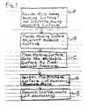
- Fig. 1is a schematic flow diagram of an improved process for imprint lithography using field-induced pressure.
- An initial step shown in Block Ais to provide a mold having a molding surface such as plurality of protruding features and a substrate having a surface of moldable material such as one or more moldable thin films.
- Protruding featuresare preferably micrometer scale features and, more advantageously, nanoscale features.
- the methodis highly advantageously where the mold surface has at least two spaced apart protruding features.
- a moldable materialis one which retains or can be hardened to retain the imprint of the protruding features from the mold surface.
- the next step, shown in Block B,is to place the mold adjacent the moldable surface. If the moldable surface is a thin film that already includes a previously formed pattern, then the pattern of the mold should be carefully aligned with the previous pattern. This can be done by alignment techniques well known in the art.
- the third step (Block C)is to press the mold onto the moldable surface by field-induced pressure.
- One method for doing thisis to dispose the assembly between conductive layers and apply an electrical field between the layers.
- Another approachis to dispose the assembly between layers of magnetic material and to apply a magnetic field that will force the layers together.
- the advantage of field-induced pressureis that the resulting force uniformly pushes the mold onto the moldable surface. Shear or rotational components are de minimus.
- the mold and/or substrateare flexible rather than rigid, conformation between the mold and the moldable surface is achieved regardless of unavoidable deviations from planarity. The result is an enhanced level of molding resolution, alignment and uniformity over an increased area of the film.
- the next step shown in Block Dis to harden the moldable surface, if necessary, so that it retains the imprint of the mold and then to remove the mold.
- the process for hardeningdepends on the material of the moldable surface. Some materials will maintain the imprint with no hardening.
- Thermoplastic materialscan be hardened by preliminarily heating them prior to molding and permitting them to cool after imprint.
- PMMAfor example, can be suitably softened by heating to 120° C prior to molding and hardened by cooling after imprint.
- Heat curable materialscan be hardened by applying heat during imprint. A heater and/or the use of a heated pressurized fluid can thus effectuate such softening or hardening.
- Radiation curable materialscan be hardened by the application of UV radiation during imprint. Silicon can be softened by UV laser radiation to accept imprinting and hardened by cooling to ambient temperature.
- the fifth step shown in Block Eis optional in some applications. It is to remove contaminants (if any) and excess material from the recesses of the molded surface.
- the molded surfacewill typically have raised features and recesses. In many lithographic operations it is desirable to eliminate the material from the recesses so that the underlying substrate is exposed for further processing. This can be conveniently accomplished using reactive ion etching.
- the imprinted structureitself is a part of a device to be built.
- the resulting structureis a resist-covered semiconductor substrate with a pattern of recesses extending toward the substrate.
- Such a structurecan be further processed in a variety of ways well-known in the art.
- the molded filmcan be used as a mask for the removal of surface layers in exposed regions of the substrate, for doping exposed regions of the substrate or for growing or depositing materials on the exposed regions.
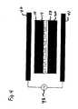
- Fig. 2schematically illustrates a first exemplary apparatus 9 for practicing the method of Fig. 1 .
- the apparatus 9comprises an assembly of a mold 10 having a molding surface 12 and a substrate 20 having a moldable surface 22.
- the mold and substrateare disposed with the molding surface 12 adjacent the moldable surface 22.
- the mold 10comprises a body having a molding surface 12.
- Surface 12can include a plurality of protruding features 13 having a desired shape for imprinting onto the moldable surface 22.
- the molding surface 12can be patterned into protruding features 13 of nanoscale dimensions by known techniques such as electron beam lithography.
- the projecting extent of the protruding features 13is typically in the range 0.1 nm to 200 ⁇ m.
- the mold 10is a multilayer structure comprising a layer of conductive or chargeable material that is distal to the interface between the molding surface and the moldable surface.
- the term layer as used hereinis intended broadly to cover a supported layer, a plate or a composite layer.
- the substrate 20is typically a solid substrate and the moldable surface 22 is typically a thin film of polymer, monomer, oligomer or combination thereof that is pliable or can be made pliable to pressure and can retain a pressure-imprinted deformation or pattern.
- Itcan be a thermoplastic polymer, such as polycarbonate or polymethyl methacrylate (PMMA), which softens in response to heat.
- PMMApolymethyl methacrylate
- itcan be a monomer liquid, such as a curable silicone, which hardens with curing.
- itcan be solid silicon which can be liquefied by a UV laser pulse.
- Polymer thin filmsare typically applied to the substrate by spraying or spinning.
- the filmdoes not adhere to the mold surface. If necessary, the mold surface can be coated with a release agent to prevent such adherence.
- the substrateis a multilayer structure comprising a layer or plate 23 of conductive or chargeable material that is distal to the molding surface/moldable surface interface.
- the pressure between the mold and the substratecan be generated by electrical or magnetic forces between the mold and the substrate.
- an attractive electrical fieldcan be established between the mold and the substrate.
- a repulsive fieldcan be used to drive the mold and the substrate together.
- an attractive magnetic force between the mold and the substratecan provide attractive pressure or repulsive external magnetic forces can drive the mold and the substrate together.
- a fieldforces the molding surface onto the moldable surface.
- this imprintingcan be effected by connecting layers 14 and 23 to opposite polarity terminals of a voltage source 30.
- the voltage from source 30can be AC, DC, pulsed, or a combination of such voltages.
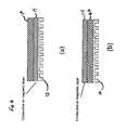
- Figs. 3A, 3B and 3Cshow substrate constructions that facilitate electrical connection with substrate conductive layer 23.
- electrical contactcan be made from the bottom of substrate 20 through conductive vias 30.
- Fig. 3Belectrical contact can be made from the bottom or from the lateral edges by coating or plating a peripheral layer 31 of conductive material around a portion of the lateral periphery of the substrate 20.
- a similar peripheral conductive layer 32is shown in Fig. 3C except that layer 32 does not extend to the bottom of the substrate.
- an electric field for imprinting the substratecan be created between appropriately dissimilar materials by the use of light, heat or RF radiation.
- the mold 10 or the substrate 20may be advantageous to make the mold 10 or the substrate 20 (including the conductive layers) of materials at least partially transparent to radiation which can be used to soften or cure the moldable surface.
- Fig. 4shows an alternative apparatus for using an electrical field to press the molding surface into the moldable surface.
- the apparatus of Fig. 4is similar to that of Fig. 2 except that rather than directly connecting the layers 14 and 23 to a voltage source, the mold 10/substrate 20 assembly is disposed between electrodes 40 and 41 that are connected to an AC voltage source 42.
- the frequency of the AC sourcecan be tuned to generate a desired induced voltage between layers 14 and 23.
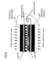
- Fig. 5illustrates alternative apparatus for practicing the method of Fig. 1 .
- the Fig. 5 apparatusis similar to the apparatus of Fig. 2 except that instead of conductive layers, magnetic layers 14A, 23A are disposed distal to the mold/substrate interface and a magnetic field is used to imprint the mold surface into the moldable surface.
- the magnetic layerscan be magnetizable material, permanent magnets or electromagnets.
- layers 14A, 23Acan comprise helically or spirally wound coils.
- Current from current sources 50A, 50B applied to coilscan produce an attractive magnetic field to press the molding surface onto the moldable surface. Connections between the current sources and their respective coils can be facilitated by conduction through conductive vias (not shown) in the substrate and the mold.
- layers 14A and 23Acan be magnetic materials that attract one another, and the current sources can be omitted.
- the moldcan comprise an electromagnet and the substrate can comprise a layer of magnetizable or permanent magnetic material or vice versa. In essence, what is needed is a magnetic layer and a magnetic field generator interacting with the magnetic layer to press the molding surface and the moldable surface together.
- Figs. 6A and 6Bshow different multilayer mold constructions useful in the embodiments of Figs. 2-5 .
- the conductive or magnetic layer 14is disposed immediately distal to the interface between the molding surface 12 and the moldable surface (not shown).
- the conductive or magnetic layer 14is still distal to the interface on the mold side, but there is an intervening layer 60.
- field-induced imprintingcan be used in conjunction with other methods of providing imprint pressure such as direct fluid pressure or mechanical pressure in all possible permutations in applying these forces, including applying them simultaneously, sequentially, or selectively.
- Fig. 7schematically illustrates additional steps compatible with the process described herein.
- Precision mechanical pressing or pressurized fluid pressingcan be of supplemental use, particularly after the molding surface is engaged with the moldable layer. Radiation, such as infrared or ultraviolet, can be used for heating, softening, or curing the moldable surface material.
- the layers 14, 23can be conductive or magnetic, and the pressing fields can be DC, AC, or combinations thereof.
Landscapes
- Engineering & Computer Science (AREA)
- Mechanical Engineering (AREA)
- Nanotechnology (AREA)
- Chemical & Material Sciences (AREA)
- Physics & Mathematics (AREA)
- General Physics & Mathematics (AREA)
- Crystallography & Structural Chemistry (AREA)
- Condensed Matter Physics & Semiconductors (AREA)
- Manufacturing & Machinery (AREA)
- Mathematical Physics (AREA)
- Theoretical Computer Science (AREA)
- Shaping Of Tube Ends By Bending Or Straightening (AREA)
- Exposure Of Semiconductors, Excluding Electron Or Ion Beam Exposure (AREA)
- Moulds For Moulding Plastics Or The Like (AREA)
- Internal Circuitry In Semiconductor Integrated Circuit Devices (AREA)
Abstract
Description
- This invention relates to imprint lithography and, in particular, to imprint lithography wherein electrical or magnetic fields are used to imprint a molding surface onto a moldable surface. The process is particularly useful to provide nanoimprint lithography of enhanced resolution and uniformity over an increased area.
- Photolithography is a key process in the fabrication of semiconductor integrated circuits and many optical, magnetic and micromechanical devices. Lithography creates a pattern on a thin film carried on a substrate so that, in subsequent process steps, the pattern can be replicated in the substrate or in another material which is added onto the substrate. Conventional lithography typically involves applying a thin film of resist to a substrate, exposing the resist to a desired pattern of radiation, and developing the exposed film to produce a physical pattern. In this approach, resolution is limited by the wavelength of the radiation, and the equipment becomes increasingly expensive as the feature size becomes smaller.
- Imprint lithography, based on a fundamentally different principle, offers high resolution, high throughput, low cost and the potential of large area coverage. In imprint lithography, a mold with microscale or nanoscale features is pressed into a thin film, deforming the shape of the film according to the features of the mold and forming a relief pattern in the film. After the mold is removed, the thin film can be processed to remove the reduced thickness portions. This removal exposes the underlying substrate for further processing. Details of imprint lithography are described in applicant's United States Patent No.
5,772,905 issued June 30, 1998 and entitled "Nanoimprint Lithography", the '905 patent. - The usual method of pressing the mold into the thin film involves positioning the mold and the substrate on respective rigid plates of a high precision mechanical press. With such apparatus, the process can generate sub-25 nm features with a high degree of uniformity over areas on the order of 12 in2. Larger areas of uniformity would be highly advantageous to increase throughput and for many applications such as displays.
- The use of a high precision mechanical press to press a mold into a thin film presents tolerance problems in replicating small patterns over large areas. Presses move on guide shafts through apertures, and the spacings between the shafts and their respective apertures can be large compared to the features to be replicated. Such spacings permit undesirable relative translational and rotational shifts between the substrate and the mold. Moreover, despite the most careful construction, the molds and the substrates used in lithography are not perfectly planar. When these molds and substrates are disposed on the rigid plates of a press, the deviations from planarity over large areas can result in variations in the molding pressure and depth of imprint. Accordingly, it is desirable to provide a method of imprint lithography which avoids the limitations of mechanical presses.
- An alternative method of pressing the mold into the thin film is the technique of fluid pressure imprint lithography described in applicant's United States Patent No.
6,482,742 issued November 19, 2002 and entitled "Fluid Pressure Imprint Lithography". In this method the molding surface is disposed adjacent the film, the molding surface/film interface is sealed and pressurized fluid is used to force the molding surface into the film. Since the pressure is isostatic, translational and rotational shifts are minimal, and smaller features can be imprinted with high uniformity over larger areas than can be imprinted using mechanical presses. - Fluid pressure imprinting has dramatically improved nanoimprint lithography. A further improvement for commercial manufacture would be a method which could provide comparable results without the necessity of sealing the molding surface/film interface.
US 5,352,394 describes an injection molding apparatus on which an injection device injects material in a molton state into a cavity, formed between two molds held together by forces applied using electromagnetic coils.US 6,056,526 describes a tool for molding an exposed surface of a resin sealant material using an elongated member comprising a magnetic material whereby pressing force is applied using a magnetic pressing member.WO00/21689 WO 03024186 - Aspects of the present invention are set out in the appended independent claims.
- An improved method of imprint lithography involves using field-induced pressure from electric or magnetic fields to press a mold into a substrate having a moldable surface. In essence, the method comprises the steps of providing a substrate having a moldable surface, providing a mold having a molding surface and pressing the molding surface and the moldable surface together by electric or magnetic fields to imprint the molding surface onto the moldable surface. The molding surface advantageously comprises a plurality of projecting features of nanoscale extent or separation, but the molding surface can also be a smooth planar surface, as for planarization. The improved method can be practiced without mechanical presses and without sealing the region between the mold and the substrate.
- The advantages, nature and various additional features of the invention will appear more fully upon consideration of the illustrative embodiments now to be described in detail in connection with the accompanying drawings. In the drawings:
Fig. 1 is a schematic flow diagram of the steps in an improved method of imprint lithography;Fig. 2 illustrates apparatus for practicing the method ofFig. 1 using an electrical field;Figs. 3A, 3B and 3C show various substrate constructions for facilitating electrical contact with a substrate conductive layer;Fig. 4 shows an alternative apparatus for practicing the method ofFig. 1 without direct electrical contact;Fig. 5 illustrates apparatus for practicing the method ofFig. 1 using a magnetic field;Fig. 6A and 6B show exemplary multilayer mold constructions useful for the apparatus ofFigs. 2 ,4 and5 ; andFig. 7 schematically illustrates how the method ofFig. 1 is compatible with a variety of other processing steps.- It is to be understood that these drawing are for purposes of illustrating the concepts of the invention and are not to scale.
- Referring to the drawings,
Fig. 1 is a schematic flow diagram of an improved process for imprint lithography using field-induced pressure. An initial step shown in Block A, is to provide a mold having a molding surface such as plurality of protruding features and a substrate having a surface of moldable material such as one or more moldable thin films. Protruding features are preferably micrometer scale features and, more advantageously, nanoscale features. The method is highly advantageously where the mold surface has at least two spaced apart protruding features. A moldable material is one which retains or can be hardened to retain the imprint of the protruding features from the mold surface. - The next step, shown in Block B, is to place the mold adjacent the moldable surface. If the moldable surface is a thin film that already includes a previously formed pattern, then the pattern of the mold should be carefully aligned with the previous pattern. This can be done by alignment techniques well known in the art.
- The third step (Block C) is to press the mold onto the moldable surface by field-induced pressure. One method for doing this is to dispose the assembly between conductive layers and apply an electrical field between the layers. Another approach is to dispose the assembly between layers of magnetic material and to apply a magnetic field that will force the layers together. The advantage of field-induced pressure is that the resulting force uniformly pushes the mold onto the moldable surface. Shear or rotational components arede minimus. Moreover since the mold and/or substrate are flexible rather than rigid, conformation between the mold and the moldable surface is achieved regardless of unavoidable deviations from planarity. The result is an enhanced level of molding resolution, alignment and uniformity over an increased area of the film.
- The next step shown in Block D, is to harden the moldable surface, if necessary, so that it retains the imprint of the mold and then to remove the mold. The process for hardening depends on the material of the moldable surface. Some materials will maintain the imprint with no hardening. Thermoplastic materials can be hardened by preliminarily heating them prior to molding and permitting them to cool after imprint. PMMA, for example, can be suitably softened by heating to 120° C prior to molding and hardened by cooling after imprint. Heat curable materials can be hardened by applying heat during imprint. A heater and/or the use of a heated pressurized fluid can thus effectuate such softening or hardening. Radiation curable materials can be hardened by the application of UV radiation during imprint. Silicon can be softened by UV laser radiation to accept imprinting and hardened by cooling to ambient temperature.
- The fifth step shown in Block E is optional in some applications. It is to remove contaminants (if any) and excess material from the recesses of the molded surface. The molded surface will typically have raised features and recesses. In many lithographic operations it is desirable to eliminate the material from the recesses so that the underlying substrate is exposed for further processing. This can be conveniently accomplished using reactive ion etching.
- In some applications, the imprinted structure itself is a part of a device to be built. In other applications the resulting structure is a resist-covered semiconductor substrate with a pattern of recesses extending toward the substrate. Such a structure can be further processed in a variety of ways well-known in the art. For example, the molded film can be used as a mask for the removal of surface layers in exposed regions of the substrate, for doping exposed regions of the substrate or for growing or depositing materials on the exposed regions.
Fig. 2 schematically illustrates a first exemplary apparatus 9 for practicing the method ofFig. 1 . The apparatus 9 comprises an assembly of amold 10 having amolding surface 12 and asubstrate 20 having amoldable surface 22. The mold and substrate are disposed with themolding surface 12 adjacent themoldable surface 22. Themold 10 comprises a body having amolding surface 12.Surface 12 can include a plurality of protruding features 13 having a desired shape for imprinting onto themoldable surface 22. Themolding surface 12 can be patterned into protruding features 13 of nanoscale dimensions by known techniques such as electron beam lithography. The projecting extent of the protruding features 13 is typically in the range 0.1 nm to 200 µm. Typical separations between protruding features are 200 nanometers or less. Advantageously themold 10 is a multilayer structure comprising a layer of conductive or chargeable material that is distal to the interface between the molding surface and the moldable surface. The term layer as used herein is intended broadly to cover a supported layer, a plate or a composite layer.- The
substrate 20 is typically a solid substrate and themoldable surface 22 is typically a thin film of polymer, monomer, oligomer or combination thereof that is pliable or can be made pliable to pressure and can retain a pressure-imprinted deformation or pattern. It can be a thermoplastic polymer, such as polycarbonate or polymethyl methacrylate (PMMA), which softens in response to heat. Alternately it can be a monomer liquid, such as a curable silicone, which hardens with curing. Yet further in the alternative, it can be solid silicon which can be liquefied by a UV laser pulse. Polymer thin films are typically applied to the substrate by spraying or spinning. Advantageously the film does not adhere to the mold surface. If necessary, the mold surface can be coated with a release agent to prevent such adherence. Advantageously the substrate is a multilayer structure comprising a layer orplate 23 of conductive or chargeable material that is distal to the molding surface/moldable surface interface. - The pressure between the mold and the substrate can be generated by electrical or magnetic forces between the mold and the substrate. For a pressure generated by an electrical force, an attractive electrical field can be established between the mold and the substrate. Alternatively a repulsive field can be used to drive the mold and the substrate together. For a pressure generated by a magnetic force, an attractive magnetic force between the mold and the substrate can provide attractive pressure or repulsive external magnetic forces can drive the mold and the substrate together.
- In use, a field forces the molding surface onto the moldable surface. In the embodiment of
Fig. 2 where the field is an electric field, this imprinting can be effected by connectinglayers voltage source 30. The voltage fromsource 30 can be AC, DC, pulsed, or a combination of such voltages. - Electrical connection with
layers substrate 20 to be conductive andmold 10 to be conductive. Alternatively, conductive through holes (not shown) throughsubstrate 20 to layer 23 and throughmold 10 to layer 14 can provide connection.Figs. 3A, 3B and 3C show substrate constructions that facilitate electrical connection with substrateconductive layer 23. InFig. 3A , electrical contact can be made from the bottom ofsubstrate 20 throughconductive vias 30. InFig. 3B electrical contact can be made from the bottom or from the lateral edges by coating or plating aperipheral layer 31 of conductive material around a portion of the lateral periphery of thesubstrate 20. A similar peripheralconductive layer 32 is shown inFig. 3C except thatlayer 32 does not extend to the bottom of the substrate. Yet further in the alternative, an electric field for imprinting the substrate can be created between appropriately dissimilar materials by the use of light, heat or RF radiation. - In some applications it may be advantageous to make the
mold 10 or the substrate 20 (including the conductive layers) of materials at least partially transparent to radiation which can be used to soften or cure the moldable surface. - In other applications it may be desired to omit one of the
conductive layers Fig. 4 shows an alternative apparatus for using an electrical field to press the molding surface into the moldable surface. The apparatus ofFig. 4 is similar to that ofFig. 2 except that rather than directly connecting thelayers mold 10/substrate 20 assembly is disposed betweenelectrodes 40 and 41 that are connected to anAC voltage source 42. The frequency of the AC source can be tuned to generate a desired induced voltage betweenlayers Fig. 5 illustrates alternative apparatus for practicing the method ofFig. 1 . TheFig. 5 apparatus is similar to the apparatus ofFig. 2 except that instead of conductive layers,magnetic layers 14A, 23A are disposed distal to the mold/substrate interface and a magnetic field is used to imprint the mold surface into the moldable surface. The magnetic layers can be magnetizable material, permanent magnets or electromagnets. For example, layers 14A, 23A can comprise helically or spirally wound coils. Current fromcurrent sources 50A, 50B applied to coils can produce an attractive magnetic field to press the molding surface onto the moldable surface. Connections between the current sources and their respective coils can be facilitated by conduction through conductive vias (not shown) in the substrate and the mold. In a modified form, layers 14A and 23A can be magnetic materials that attract one another, and the current sources can be omitted. In another variation, the mold can comprise an electromagnet and the substrate can comprise a layer of magnetizable or permanent magnetic material or vice versa. In essence, what is needed is a magnetic layer and a magnetic field generator interacting with the magnetic layer to press the molding surface and the moldable surface together.Figs. 6A and 6B show different multilayer mold constructions useful in the embodiments ofFigs. 2-5 . InFig. 6A , the conductive ormagnetic layer 14 is disposed immediately distal to the interface between themolding surface 12 and the moldable surface (not shown). InFig. 6B , the conductive ormagnetic layer 14 is still distal to the interface on the mold side, but there is an intervening layer 60.- It is further contemplated that field-induced imprinting can be used in conjunction with other methods of providing imprint pressure such as direct fluid pressure or mechanical pressure in all possible permutations in applying these forces, including applying them simultaneously, sequentially, or selectively.
Fig. 7 schematically illustrates additional steps compatible with the process described herein. Precision mechanical pressing or pressurized fluid pressing can be of supplemental use, particularly after the molding surface is engaged with the moldable layer. Radiation, such as infrared or ultraviolet, can be used for heating, softening, or curing the moldable surface material. Thelayers - It is to be understood that the above described embodiments are illustrative of only a few of the many embodiments which can represent applications of the invention. Numerous and varied other arrangements can be made by those skilled in the art without departing from the scope of the invention which is defined by the attached claims.
Claims (23)
- A method of nano-imprint lithography for processing a moldable surface (22) comprising the steps of:providing (A) a substrate (20) having the moldable surface;providing (A) a mold (10) having a molding surface (12) patterned with protruding features of nanoscale dimensions;pressing (C) the molding surface and the moldable surface together by electric or magnetic field induced pressure to imprint the molding surface onto the moldable surface at an interface between the moldable and molding surfaces; andwithdrawing (D) the mold from the moldable surface;characterised in that, in the case of electric field induced pressure, the mold and substrate comprise multilayer structures (10,20) comprising respective layers (14,23) of chargeable or conductive material distal to the interface between the molding surface and the moldable surface; andin the case of magnetic field induced pressure, the mold and the substrate comprise multilayer structures (10,20) comprising respective layers (14A,23A) of magnetic material distal to the interface between the molding surface and the moldable surface; andwherein at least one of the multilayer structures is flexible.
- The method of claim 1 wherein the moldable surface comprises one or more moldable layers disposed on the substrate.
- The method of claim 2 wherein the imprinting produces reduced thickness regions in the moldable layer and further comprising the steps of:removing the material of the moldable layer from the reduced thickness regions to selectively expose regions of the substrate; andfurther processing the substrate selectively in the exposed regions.
- The method of claim 3 wherein the further processing comprises doping the substrate with impurities, removing material from the substrate, or adding material on the substrate.
- The method of claim 1 further comprising the step of hardening (D) the moldable surface after pressing.
- The method of claim 1 wherein the substrate or the mold or both are sufficiently flexible to conform together under the pressure.
- The method of claim 2 where the thickness of the moldable layer is in the range 0.1 nm to 200 µm.
- Nano-imprint lithography apparatus for imprinting a moldable surface (22) on a substrate (20), the apparatus comprising:a mold (10) having a molding surface (12) patterned with protruding features (13) of nanoscale dimensions;a substrate (20) having a moldable surface (22) positioned adjacent the molding surface of the mold;means (14,23) for forming an electrical field between the mold and substrate to press the molding surface and the moldable surface together at an interface between the moldable and molding surfaces;characterised in that the mold and substrate comprise multilayer structures (10,20) comprising respective first and second layers (14,22) of chargeable or conductive material distal to the interface between the molding surface and the moldable surface; andwherein at least one of the multilayer structures is flexible.
- The apparatus of claim 8 wherein at least one of the first and second layers is conductive and the means for forming an electrical field comprises a voltage source (30).
- The apparatus of claim 9 wherein the first and second layers comprise conductive material.
- The apparatus of claim 9 wherein the voltage source comprises a DC voltage source.
- The apparatus of claim 9 wherein the voltage source comprises an AC voltage source.
- The apparatus of claim 9 wherein the voltage source comprises a pulsed voltage source.
- The apparatus of claim 9 wherein the voltage source can provide a combination of DC, AC and pulsed voltage.
- The apparatus of claim 9 wherein the mold includes a conductive layer (14).
- The apparatus of claim 10 wherein the voltage source is connected between the layers of conductive material.
- The apparatus of claim 9 wherein the mold and the substrate are disposed between at least two external electrodes (40,41) and the means for forming an electrical field comprises a voltage source to apply a voltage between the external electrodes.
- The apparatus of claim 17 wherein the voltage source is an AC or pulsed voltage source.
- Nano-imprint lithography apparatus for imprinting a moldable surface on a substrate (20) comprising:a mold (10) having a molding surface (22) patterned with protruding features (13) of nanoscale dimensions;a substrate (20) having a moldable surface positioned adjacent the molding surface;and a magnetic field generator (50A, 50B) adapted to generate a magnetic field to press the molding surface and the moldable surface together at an interface between the moldable and molding surfaces;characterised in that the mold and the substrate comprise multilayer structures (10,20) comprising respective layers (14A,23A) of magnetic material distal to the interface between the molding surface and the moldable surface; andwherein at least one of the multilayer structures is flexible.
- The apparatus of claim 19 wherein the magnetic layer comprises a conductive coil or spiral.
- The apparatus of claim 19 wherein the magnetic field generator comprises a conductive coil or spiral.
- The apparatus of claim 19 wherein the magnetic layer comprises a layer of magnetized material.
- The apparatus of claim 19 wherein the magnetic layer comprises a layer of magnetizable material.
Applications Claiming Priority (5)
| Application Number | Priority Date | Filing Date | Title |
|---|---|---|---|
| US38296102P | 2002-05-24 | 2002-05-24 | |
| US382961P | 2002-05-24 | ||
| US244276 | 2002-09-16 | ||
| US10/244,276US20030080471A1 (en) | 2001-10-29 | 2002-09-16 | Lithographic method for molding pattern with nanoscale features |
| PCT/US2003/018020WO2003099536A1 (en) | 2002-05-24 | 2003-05-27 | Methods and apparatus of field-induced pressure imprint lithography |
Publications (3)
| Publication Number | Publication Date |
|---|---|
| EP1509379A1 EP1509379A1 (en) | 2005-03-02 |
| EP1509379A4 EP1509379A4 (en) | 2007-08-08 |
| EP1509379B1true EP1509379B1 (en) | 2012-02-29 |
Family
ID=29586448
Family Applications (1)
| Application Number | Title | Priority Date | Filing Date |
|---|---|---|---|
| EP03734468AExpired - LifetimeEP1509379B1 (en) | 2002-05-24 | 2003-05-27 | Methods and apparatus of field-induced pressure imprint lithography |
Country Status (6)
| Country | Link |
|---|---|
| EP (1) | EP1509379B1 (en) |
| JP (1) | JP2005527974A (en) |
| KR (1) | KR20050036912A (en) |
| CN (1) | CN1678443B (en) |
| AU (1) | AU2003238947A1 (en) |
| WO (1) | WO2003099536A1 (en) |
Families Citing this family (73)
| Publication number | Priority date | Publication date | Assignee | Title |
|---|---|---|---|---|
| US6873087B1 (en) | 1999-10-29 | 2005-03-29 | Board Of Regents, The University Of Texas System | High precision orientation alignment and gap control stages for imprint lithography processes |
| SE516194C2 (en)* | 2000-04-18 | 2001-12-03 | Obducat Ab | Substrate for and process of fabrication of structures |
| SE516414C2 (en)* | 2000-05-24 | 2002-01-15 | Obducat Ab | Method of producing a template, as well as the template made from it |
| AU2001273491A1 (en) | 2000-07-16 | 2002-02-05 | Board Of Regents, The University Of Texas System | High-resolution overlay alignment methods and systems for imprint lithography |
| JP2004505273A (en) | 2000-08-01 | 2004-02-19 | ボード・オブ・リージエンツ,ザ・ユニバーシテイ・オブ・テキサス・システム | Method for highly accurate sensing of gap and orientation between transparent template and substrate for transfer lithography |
| EP1352295B1 (en) | 2000-10-12 | 2015-12-23 | Board of Regents, The University of Texas System | Template for room temperature, low pressure micro- and nano-imprint lithography |
| US6964793B2 (en) | 2002-05-16 | 2005-11-15 | Board Of Regents, The University Of Texas System | Method for fabricating nanoscale patterns in light curable compositions using an electric field |
| US7037639B2 (en) | 2002-05-01 | 2006-05-02 | Molecular Imprints, Inc. | Methods of manufacturing a lithography template |
| US7179079B2 (en) | 2002-07-08 | 2007-02-20 | Molecular Imprints, Inc. | Conforming template for patterning liquids disposed on substrates |
| US6926929B2 (en) | 2002-07-09 | 2005-08-09 | Molecular Imprints, Inc. | System and method for dispensing liquids |
| US7442336B2 (en) | 2003-08-21 | 2008-10-28 | Molecular Imprints, Inc. | Capillary imprinting technique |
| US6908861B2 (en) | 2002-07-11 | 2005-06-21 | Molecular Imprints, Inc. | Method for imprint lithography using an electric field |
| US7019819B2 (en) | 2002-11-13 | 2006-03-28 | Molecular Imprints, Inc. | Chucking system for modulating shapes of substrates |
| US7027156B2 (en) | 2002-08-01 | 2006-04-11 | Molecular Imprints, Inc. | Scatterometry alignment for imprint lithography |
| US7070405B2 (en) | 2002-08-01 | 2006-07-04 | Molecular Imprints, Inc. | Alignment systems for imprint lithography |
| US6871558B2 (en) | 2002-12-12 | 2005-03-29 | Molecular Imprints, Inc. | Method for determining characteristics of substrate employing fluid geometries |
| US7365103B2 (en) | 2002-12-12 | 2008-04-29 | Board Of Regents, The University Of Texas System | Compositions for dark-field polymerization and method of using the same for imprint lithography processes |
| MY136129A (en) | 2002-12-13 | 2008-08-29 | Molecular Imprints Inc | Magnification correction employing out-of-plane distortion of a substrate |
| US7122079B2 (en) | 2004-02-27 | 2006-10-17 | Molecular Imprints, Inc. | Composition for an etching mask comprising a silicon-containing material |
| US7186656B2 (en) | 2004-05-21 | 2007-03-06 | Molecular Imprints, Inc. | Method of forming a recessed structure employing a reverse tone process |
| US7396475B2 (en) | 2003-04-25 | 2008-07-08 | Molecular Imprints, Inc. | Method of forming stepped structures employing imprint lithography |
| US6951173B1 (en) | 2003-05-14 | 2005-10-04 | Molecular Imprints, Inc. | Assembly and method for transferring imprint lithography templates |
| US7157036B2 (en) | 2003-06-17 | 2007-01-02 | Molecular Imprints, Inc | Method to reduce adhesion between a conformable region and a pattern of a mold |
| US7150622B2 (en) | 2003-07-09 | 2006-12-19 | Molecular Imprints, Inc. | Systems for magnification and distortion correction for imprint lithography processes |
| US7136150B2 (en) | 2003-09-25 | 2006-11-14 | Molecular Imprints, Inc. | Imprint lithography template having opaque alignment marks |
| US7090716B2 (en)* | 2003-10-02 | 2006-08-15 | Molecular Imprints, Inc. | Single phase fluid imprint lithography method |
| US7261830B2 (en) | 2003-10-16 | 2007-08-28 | Molecular Imprints, Inc. | Applying imprinting material to substrates employing electromagnetic fields |
| US7122482B2 (en) | 2003-10-27 | 2006-10-17 | Molecular Imprints, Inc. | Methods for fabricating patterned features utilizing imprint lithography |
| EP1730591B1 (en)* | 2004-01-12 | 2011-08-03 | Regents of the University of California | Nanoscale electric lithography |
| US7019835B2 (en) | 2004-02-19 | 2006-03-28 | Molecular Imprints, Inc. | Method and system to measure characteristics of a film disposed on a substrate |
| CN101427182B (en)* | 2004-04-27 | 2011-10-19 | 伊利诺伊大学评议会 | Composite patterning equipment for soft lithography |
| US7140861B2 (en) | 2004-04-27 | 2006-11-28 | Molecular Imprints, Inc. | Compliant hard template for UV imprinting |
| US7105452B2 (en) | 2004-08-13 | 2006-09-12 | Molecular Imprints, Inc. | Method of planarizing a semiconductor substrate with an etching chemistry |
| US7309225B2 (en) | 2004-08-13 | 2007-12-18 | Molecular Imprints, Inc. | Moat system for an imprint lithography template |
| US7282550B2 (en) | 2004-08-16 | 2007-10-16 | Molecular Imprints, Inc. | Composition to provide a layer with uniform etch characteristics |
| US7041604B2 (en) | 2004-09-21 | 2006-05-09 | Molecular Imprints, Inc. | Method of patterning surfaces while providing greater control of recess anisotropy |
| US7241395B2 (en) | 2004-09-21 | 2007-07-10 | Molecular Imprints, Inc. | Reverse tone patterning on surfaces having planarity perturbations |
| US7205244B2 (en) | 2004-09-21 | 2007-04-17 | Molecular Imprints | Patterning substrates employing multi-film layers defining etch-differential interfaces |
| US7547504B2 (en) | 2004-09-21 | 2009-06-16 | Molecular Imprints, Inc. | Pattern reversal employing thick residual layers |
| US7252777B2 (en) | 2004-09-21 | 2007-08-07 | Molecular Imprints, Inc. | Method of forming an in-situ recessed structure |
| US7244386B2 (en)* | 2004-09-27 | 2007-07-17 | Molecular Imprints, Inc. | Method of compensating for a volumetric shrinkage of a material disposed upon a substrate to form a substantially planar structure therefrom |
| CN100395121C (en)* | 2004-11-19 | 2008-06-18 | 鸿富锦精密工业(深圳)有限公司 | hot embossing method |
| US7922474B2 (en) | 2005-02-17 | 2011-04-12 | Asml Netherlands B.V. | Imprint lithography |
| KR101264754B1 (en)* | 2005-03-23 | 2013-05-15 | 에이저 시스템즈 엘엘시 | A method for manufacturing a device using imprint lithography and direct write technology |
| JP4716819B2 (en)* | 2005-08-22 | 2011-07-06 | 新光電気工業株式会社 | Manufacturing method of interposer |
| JP4766964B2 (en)* | 2005-09-06 | 2011-09-07 | 日本電信電話株式会社 | Nanoimprint method |
| US7976748B2 (en) | 2005-09-15 | 2011-07-12 | The Board Of Trustees Of The University Of Illinois | Nano-molding process |
| JP2007157962A (en)* | 2005-12-05 | 2007-06-21 | Sumitomo Electric Ind Ltd | Molding tool |
| US7670530B2 (en)* | 2006-01-20 | 2010-03-02 | Molecular Imprints, Inc. | Patterning substrates employing multiple chucks |
| JP4654299B2 (en)* | 2006-09-15 | 2011-03-16 | 株式会社日立ハイテクノロジーズ | Scanning electron microscope point aberration measurement alignment chip |
| JP4978996B2 (en)* | 2006-11-20 | 2012-07-18 | リコーエレメックス株式会社 | Manufacturing method of through-hole structure |
| KR101341782B1 (en) | 2006-12-29 | 2013-12-13 | 엘지디스플레이 주식회사 | System for Molding, Method for Foming Pattern and Method for Manufacturing Liquid Crystal Display Device |
| US20100108639A1 (en)* | 2007-03-30 | 2010-05-06 | Pioneer Corporation | Imprinting mold and method of producing imprinting mold |
| US8142702B2 (en)* | 2007-06-18 | 2012-03-27 | Molecular Imprints, Inc. | Solvent-assisted layer formation for imprint lithography |
| JP5301872B2 (en)* | 2007-08-29 | 2013-09-25 | 国立大学法人東北大学 | Thiol group-containing UV-sensitive compound and use thereof |
| JP5305220B2 (en)* | 2007-11-12 | 2013-10-02 | 株式会社ニコン | Substrate bonding device |
| JPWO2009084392A1 (en)* | 2007-12-27 | 2011-05-19 | アルプス電気株式会社 | Mold apparatus and method for manufacturing resin molded product |
| JP5376930B2 (en)* | 2008-12-19 | 2013-12-25 | キヤノン株式会社 | Method for manufacturing liquid discharge head |
| TWI448396B (en)* | 2009-03-27 | 2014-08-11 | Hon Hai Prec Ind Co Ltd | Imprinting apparatus |
| JP2010258106A (en) | 2009-04-22 | 2010-11-11 | Toshiba Corp | Pattern transfer method |
| US8268226B2 (en)* | 2009-07-07 | 2012-09-18 | The Boeing Company | Curing system and method using electromagnetic force and conductive heat transfer |
| EP2286981B1 (en) | 2009-08-22 | 2012-12-12 | EV Group E. Thallner GmbH | Process for heat embossing a polymer layer |
| JP5033867B2 (en)* | 2009-12-28 | 2012-09-26 | 株式会社日立ハイテクノロジーズ | Fine structure, method for producing fine structure, and polymerizable resin composition for producing fine structure |
| JP2011216808A (en)* | 2010-04-02 | 2011-10-27 | Toshiba Mach Co Ltd | Transfer device, transfer system, and transfer method |
| FR2959162B3 (en)* | 2010-04-26 | 2012-03-23 | Innopsys | SOFT LITHOGRAPHY DEVICE AND METHOD |
| CN102243436B (en)* | 2011-06-07 | 2013-04-17 | 西安交通大学 | Electric-field-induced micro-compounding method under geometrical restraint |
| JP5154675B2 (en)* | 2011-06-08 | 2013-02-27 | シャープ株式会社 | Resin molding apparatus and resin molding method |
| JP5203493B2 (en) | 2011-09-29 | 2013-06-05 | シャープ株式会社 | Molding apparatus and molding method |
| JP6244742B2 (en)* | 2013-08-26 | 2017-12-13 | 大日本印刷株式会社 | Film inspection method, imprint method, pattern structure manufacturing method, imprint mold, imprint transfer substrate, and imprint apparatus |
| JP6527474B2 (en)* | 2016-02-05 | 2019-06-05 | 東芝メモリ株式会社 | Imprint method |
| CN109188862A (en)* | 2018-10-11 | 2019-01-11 | 京东方科技集团股份有限公司 | Stamping structure and its manufacturing method, impression block |
| KR102542639B1 (en)* | 2021-02-10 | 2023-06-12 | 성균관대학교산학협력단 | Apparatus and method for forming fine pattern |
| KR102528880B1 (en)* | 2021-02-16 | 2023-05-03 | 성균관대학교산학협력단 | Fabrication of nanostructrues by secondary interference effect between microstructures using electrohydrodynamic instability patterning technology and method of manufacturing superhydrophobic surface |
Family Cites Families (8)
| Publication number | Priority date | Publication date | Assignee | Title |
|---|---|---|---|---|
| DE3719200A1 (en)* | 1987-06-09 | 1988-12-29 | Ibm Deutschland | OPTICAL DISK AND METHOD FOR THEIR PRODUCTION |
| TW205018B (en)* | 1990-11-30 | 1993-05-01 | Toshiba Machine Co Ltd | |
| US6056526A (en)* | 1994-11-30 | 2000-05-02 | 3M Innovative Properties Company | Molding tool for sealant material |
| US6482742B1 (en)* | 2000-07-18 | 2002-11-19 | Stephen Y. Chou | Fluid pressure imprint lithography |
| WO2000021689A1 (en)* | 1998-10-09 | 2000-04-20 | The Trustees Of Princeton University | Microscale patterning and articles formed thereby |
| JP2001277200A (en)* | 2000-03-30 | 2001-10-09 | Toshiba Corp | Micro processing equipment |
| US6964793B2 (en)* | 2002-05-16 | 2005-11-15 | Board Of Regents, The University Of Texas System | Method for fabricating nanoscale patterns in light curable compositions using an electric field |
| WO2003024186A2 (en)* | 2001-09-18 | 2003-03-27 | Eidgenossische Technische Hochschule Zurich | Methods and apparatus for patterning a surface |
- 2003
- 2003-05-27CNCN03816008.0Apatent/CN1678443B/ennot_activeExpired - Fee Related
- 2003-05-27KRKR1020047018882Apatent/KR20050036912A/ennot_activeCeased
- 2003-05-27EPEP03734468Apatent/EP1509379B1/ennot_activeExpired - Lifetime
- 2003-05-27AUAU2003238947Apatent/AU2003238947A1/ennot_activeAbandoned
- 2003-05-27WOPCT/US2003/018020patent/WO2003099536A1/enactiveApplication Filing
- 2003-05-27JPJP2004507045Apatent/JP2005527974A/enactivePending
Also Published As
| Publication number | Publication date |
|---|---|
| WO2003099536A1 (en) | 2003-12-04 |
| JP2005527974A (en) | 2005-09-15 |
| AU2003238947A1 (en) | 2003-12-12 |
| CN1678443B (en) | 2012-12-19 |
| CN1678443A (en) | 2005-10-05 |
| EP1509379A1 (en) | 2005-03-02 |
| KR20050036912A (en) | 2005-04-20 |
| EP1509379A4 (en) | 2007-08-08 |
Similar Documents
| Publication | Publication Date | Title |
|---|---|---|
| EP1509379B1 (en) | Methods and apparatus of field-induced pressure imprint lithography | |
| US7887739B2 (en) | Methods and apparatus of pressure imprint lithography | |
| US8333583B2 (en) | Methods and apparatus for rapid imprint lithography | |
| JP5276436B2 (en) | Pattern duplication with intermediate stamp | |
| US7363854B2 (en) | System and method for patterning both sides of a substrate utilizing imprint lithography | |
| US6964793B2 (en) | Method for fabricating nanoscale patterns in light curable compositions using an electric field | |
| US20050146078A1 (en) | Apparatus for double-sided imprint lithography | |
| JP2008542081A5 (en) | ||
| EP2033050B1 (en) | Manufacturing a replication tool | |
| KR101413233B1 (en) | Nano-imprint lithography process | |
| KR100577973B1 (en) | Fine pattern formation method using dewetting | |
| KR100526053B1 (en) | Mold using amorphous fluorine resin and fabrication method thereof | |
| US7261830B2 (en) | Applying imprinting material to substrates employing electromagnetic fields | |
| US7128559B1 (en) | Programmable imprint lithography template | |
| KR100492851B1 (en) | Method for fabricating micro pattern on surface by using buckling phenomenon | |
| Schumaker et al. | Applying imprinting material to substrates employing electromagnetic fields | |
| TW200919098A (en) | Magnetic-force imprint system and method | |
| JP2000246738A (en) | Mold for resin mold | |
| HK1114185A1 (en) | Method for imprint lithography at constant temperature | |
| HK1114185B (en) | Method for imprint lithography at constant temperature | |
| HK1121243B (en) | Pattern replication with intermediate stamp | |
| HK1096162B (en) | Pattern replication with intermediate stamp |
Legal Events
| Date | Code | Title | Description |
|---|---|---|---|
| PUAI | Public reference made under article 153(3) epc to a published international application that has entered the european phase | Free format text:ORIGINAL CODE: 0009012 | |
| 17P | Request for examination filed | Effective date:20041210 | |
| AK | Designated contracting states | Kind code of ref document:A1 Designated state(s):AT BE BG CH CY CZ DE DK EE ES FI FR GB GR HU IE IT LI LU MC NL PT RO SE SI SK TR | |
| AX | Request for extension of the european patent | Extension state:AL LT LV MK | |
| DAX | Request for extension of the european patent (deleted) | ||
| A4 | Supplementary search report drawn up and despatched | Effective date:20070709 | |
| 17Q | First examination report despatched | Effective date:20100205 | |
| GRAP | Despatch of communication of intention to grant a patent | Free format text:ORIGINAL CODE: EPIDOSNIGR1 | |
| GRAS | Grant fee paid | Free format text:ORIGINAL CODE: EPIDOSNIGR3 | |
| GRAA | (expected) grant | Free format text:ORIGINAL CODE: 0009210 | |
| AK | Designated contracting states | Kind code of ref document:B1 Designated state(s):AT BE BG CH CY CZ DE DK EE ES FI FR GB GR HU IE IT LI LU MC NL PT RO SE SI SK TR | |
| REG | Reference to a national code | Ref country code:GB Ref legal event code:FG4D Ref country code:CH Ref legal event code:EP | |
| REG | Reference to a national code | Ref country code:AT Ref legal event code:REF Ref document number:547223 Country of ref document:AT Kind code of ref document:T Effective date:20120315 | |
| REG | Reference to a national code | Ref country code:IE Ref legal event code:FG4D | |
| REG | Reference to a national code | Ref country code:DE Ref legal event code:R096 Ref document number:60340131 Country of ref document:DE Effective date:20120419 | |
| REG | Reference to a national code | Ref country code:NL Ref legal event code:VDEP Effective date:20120229 | |
| PG25 | Lapsed in a contracting state [announced via postgrant information from national office to epo] | Ref country code:NL Free format text:LAPSE BECAUSE OF FAILURE TO SUBMIT A TRANSLATION OF THE DESCRIPTION OR TO PAY THE FEE WITHIN THE PRESCRIBED TIME-LIMIT Effective date:20120229 | |
| PGFP | Annual fee paid to national office [announced via postgrant information from national office to epo] | Ref country code:DE Payment date:20120529 Year of fee payment:10 | |
| PG25 | Lapsed in a contracting state [announced via postgrant information from national office to epo] | Ref country code:BE Free format text:LAPSE BECAUSE OF FAILURE TO SUBMIT A TRANSLATION OF THE DESCRIPTION OR TO PAY THE FEE WITHIN THE PRESCRIBED TIME-LIMIT Effective date:20120229 Ref country code:GR Free format text:LAPSE BECAUSE OF FAILURE TO SUBMIT A TRANSLATION OF THE DESCRIPTION OR TO PAY THE FEE WITHIN THE PRESCRIBED TIME-LIMIT Effective date:20120530 Ref country code:FI Free format text:LAPSE BECAUSE OF FAILURE TO SUBMIT A TRANSLATION OF THE DESCRIPTION OR TO PAY THE FEE WITHIN THE PRESCRIBED TIME-LIMIT Effective date:20120229 Ref country code:PT Free format text:LAPSE BECAUSE OF FAILURE TO SUBMIT A TRANSLATION OF THE DESCRIPTION OR TO PAY THE FEE WITHIN THE PRESCRIBED TIME-LIMIT Effective date:20120629 | |
| PGFP | Annual fee paid to national office [announced via postgrant information from national office to epo] | Ref country code:FR Payment date:20120607 Year of fee payment:10 | |
| REG | Reference to a national code | Ref country code:AT Ref legal event code:MK05 Ref document number:547223 Country of ref document:AT Kind code of ref document:T Effective date:20120229 | |
| PG25 | Lapsed in a contracting state [announced via postgrant information from national office to epo] | Ref country code:CY Free format text:LAPSE BECAUSE OF FAILURE TO SUBMIT A TRANSLATION OF THE DESCRIPTION OR TO PAY THE FEE WITHIN THE PRESCRIBED TIME-LIMIT Effective date:20120229 | |
| PG25 | Lapsed in a contracting state [announced via postgrant information from national office to epo] | Ref country code:SI Free format text:LAPSE BECAUSE OF FAILURE TO SUBMIT A TRANSLATION OF THE DESCRIPTION OR TO PAY THE FEE WITHIN THE PRESCRIBED TIME-LIMIT Effective date:20120229 Ref country code:SE Free format text:LAPSE BECAUSE OF FAILURE TO SUBMIT A TRANSLATION OF THE DESCRIPTION OR TO PAY THE FEE WITHIN THE PRESCRIBED TIME-LIMIT Effective date:20120229 Ref country code:RO Free format text:LAPSE BECAUSE OF FAILURE TO SUBMIT A TRANSLATION OF THE DESCRIPTION OR TO PAY THE FEE WITHIN THE PRESCRIBED TIME-LIMIT Effective date:20120229 Ref country code:CZ Free format text:LAPSE BECAUSE OF FAILURE TO SUBMIT A TRANSLATION OF THE DESCRIPTION OR TO PAY THE FEE WITHIN THE PRESCRIBED TIME-LIMIT Effective date:20120229 Ref country code:EE Free format text:LAPSE BECAUSE OF FAILURE TO SUBMIT A TRANSLATION OF THE DESCRIPTION OR TO PAY THE FEE WITHIN THE PRESCRIBED TIME-LIMIT Effective date:20120229 Ref country code:DK Free format text:LAPSE BECAUSE OF FAILURE TO SUBMIT A TRANSLATION OF THE DESCRIPTION OR TO PAY THE FEE WITHIN THE PRESCRIBED TIME-LIMIT Effective date:20120229 | |
| PG25 | Lapsed in a contracting state [announced via postgrant information from national office to epo] | Ref country code:IT Free format text:LAPSE BECAUSE OF FAILURE TO SUBMIT A TRANSLATION OF THE DESCRIPTION OR TO PAY THE FEE WITHIN THE PRESCRIBED TIME-LIMIT Effective date:20120229 Ref country code:SK Free format text:LAPSE BECAUSE OF FAILURE TO SUBMIT A TRANSLATION OF THE DESCRIPTION OR TO PAY THE FEE WITHIN THE PRESCRIBED TIME-LIMIT Effective date:20120229 | |
| PG25 | Lapsed in a contracting state [announced via postgrant information from national office to epo] | Ref country code:MC Free format text:LAPSE BECAUSE OF NON-PAYMENT OF DUE FEES Effective date:20120531 | |
| REG | Reference to a national code | Ref country code:CH Ref legal event code:PL | |
| PLBE | No opposition filed within time limit | Free format text:ORIGINAL CODE: 0009261 | |
| STAA | Information on the status of an ep patent application or granted ep patent | Free format text:STATUS: NO OPPOSITION FILED WITHIN TIME LIMIT | |
| GBPC | Gb: european patent ceased through non-payment of renewal fee | Effective date:20120529 | |
| PG25 | Lapsed in a contracting state [announced via postgrant information from national office to epo] | Ref country code:AT Free format text:LAPSE BECAUSE OF FAILURE TO SUBMIT A TRANSLATION OF THE DESCRIPTION OR TO PAY THE FEE WITHIN THE PRESCRIBED TIME-LIMIT Effective date:20120229 Ref country code:CH Free format text:LAPSE BECAUSE OF NON-PAYMENT OF DUE FEES Effective date:20120531 Ref country code:LI Free format text:LAPSE BECAUSE OF NON-PAYMENT OF DUE FEES Effective date:20120531 | |
| 26N | No opposition filed | Effective date:20121130 | |
| REG | Reference to a national code | Ref country code:IE Ref legal event code:MM4A | |
| REG | Reference to a national code | Ref country code:DE Ref legal event code:R097 Ref document number:60340131 Country of ref document:DE Effective date:20121130 | |
| PG25 | Lapsed in a contracting state [announced via postgrant information from national office to epo] | Ref country code:GB Free format text:LAPSE BECAUSE OF NON-PAYMENT OF DUE FEES Effective date:20120529 Ref country code:ES Free format text:LAPSE BECAUSE OF FAILURE TO SUBMIT A TRANSLATION OF THE DESCRIPTION OR TO PAY THE FEE WITHIN THE PRESCRIBED TIME-LIMIT Effective date:20120609 Ref country code:IE Free format text:LAPSE BECAUSE OF NON-PAYMENT OF DUE FEES Effective date:20120527 | |
| PG25 | Lapsed in a contracting state [announced via postgrant information from national office to epo] | Ref country code:BG Free format text:LAPSE BECAUSE OF FAILURE TO SUBMIT A TRANSLATION OF THE DESCRIPTION OR TO PAY THE FEE WITHIN THE PRESCRIBED TIME-LIMIT Effective date:20120529 | |
| PG25 | Lapsed in a contracting state [announced via postgrant information from national office to epo] | Ref country code:DE Free format text:LAPSE BECAUSE OF NON-PAYMENT OF DUE FEES Effective date:20131203 | |
| REG | Reference to a national code | Ref country code:DE Ref legal event code:R119 Ref document number:60340131 Country of ref document:DE Effective date:20131203 | |
| REG | Reference to a national code | Ref country code:FR Ref legal event code:ST Effective date:20140131 | |
| PG25 | Lapsed in a contracting state [announced via postgrant information from national office to epo] | Ref country code:TR Free format text:LAPSE BECAUSE OF FAILURE TO SUBMIT A TRANSLATION OF THE DESCRIPTION OR TO PAY THE FEE WITHIN THE PRESCRIBED TIME-LIMIT Effective date:20120229 | |
| PG25 | Lapsed in a contracting state [announced via postgrant information from national office to epo] | Ref country code:LU Free format text:LAPSE BECAUSE OF NON-PAYMENT OF DUE FEES Effective date:20120527 Ref country code:FR Free format text:LAPSE BECAUSE OF NON-PAYMENT OF DUE FEES Effective date:20130531 | |
| PG25 | Lapsed in a contracting state [announced via postgrant information from national office to epo] | Ref country code:HU Free format text:LAPSE BECAUSE OF FAILURE TO SUBMIT A TRANSLATION OF THE DESCRIPTION OR TO PAY THE FEE WITHIN THE PRESCRIBED TIME-LIMIT Effective date:20030527 |