EP1508443B1 - Inkjet printer with electro-magnetically actuated ink plunger - Google Patents
Inkjet printer with electro-magnetically actuated ink plungerDownload PDFInfo
- Publication number
- EP1508443B1 EP1508443B1EP04024057AEP04024057AEP1508443B1EP 1508443 B1EP1508443 B1EP 1508443B1EP 04024057 AEP04024057 AEP 04024057AEP 04024057 AEP04024057 AEP 04024057AEP 1508443 B1EP1508443 B1EP 1508443B1
- Authority
- EP
- European Patent Office
- Prior art keywords
- ink
- nozzle
- actuator
- plunger
- ink jet
- Prior art date
- Legal status (The legal status is an assumption and is not a legal conclusion. Google has not performed a legal analysis and makes no representation as to the accuracy of the status listed.)
- Expired - Lifetime
Links
- 230000033001locomotionEffects0.000claimsabstractdescription42
- 239000012530fluidSubstances0.000claimsabstractdescription12
- 230000004913activationEffects0.000claimsabstractdescription11
- 238000004891communicationMethods0.000claimsabstractdescription3
- 238000010276constructionMethods0.000claimsdescription32
- 239000000696magnetic materialSubstances0.000claimsdescription8
- 230000005291magnetic effectEffects0.000abstractdescription54
- 238000007641inkjet printingMethods0.000abstractdescription17
- 239000000976inkSubstances0.000description284
- 238000004519manufacturing processMethods0.000description49
- 238000000034methodMethods0.000description46
- 239000000463materialSubstances0.000description31
- 230000007246mechanismEffects0.000description21
- 230000008901benefitEffects0.000description18
- 238000007639printingMethods0.000description16
- 230000008569processEffects0.000description16
- XUIMIQQOPSSXEZ-UHFFFAOYSA-NSiliconChemical compound[Si]XUIMIQQOPSSXEZ-UHFFFAOYSA-N0.000description13
- 238000005516engineering processMethods0.000description13
- 229920001343polytetrafluoroethylenePolymers0.000description13
- 239000004810polytetrafluoroethyleneSubstances0.000description13
- 229910052710siliconInorganic materials0.000description13
- 239000010703siliconSubstances0.000description13
- RYGMFSIKBFXOCR-UHFFFAOYSA-NCopperChemical compound[Cu]RYGMFSIKBFXOCR-UHFFFAOYSA-N0.000description12
- 229910052802copperInorganic materials0.000description12
- 239000010949copperSubstances0.000description12
- 230000035882stressEffects0.000description12
- 238000013461designMethods0.000description11
- 230000009467reductionEffects0.000description11
- 230000002441reversible effectEffects0.000description11
- ZWEHNKRNPOVVGH-UHFFFAOYSA-N2-ButanoneChemical compoundCCC(C)=OZWEHNKRNPOVVGH-UHFFFAOYSA-N0.000description9
- 239000000049pigmentSubstances0.000description9
- 230000005684electric fieldEffects0.000description8
- 239000011521glassSubstances0.000description7
- 238000000926separation methodMethods0.000description7
- 239000000758substrateSubstances0.000description7
- 238000012546transferMethods0.000description7
- XLYOFNOQVPJJNP-UHFFFAOYSA-NwaterSubstancesOXLYOFNOQVPJJNP-UHFFFAOYSA-N0.000description7
- 235000009899Agrostemma githagoNutrition0.000description6
- ZOXJGFHDIHLPTG-UHFFFAOYSA-NBoronChemical compound[B]ZOXJGFHDIHLPTG-UHFFFAOYSA-N0.000description6
- XEEYBQQBJWHFJM-UHFFFAOYSA-NIronChemical compound[Fe]XEEYBQQBJWHFJM-UHFFFAOYSA-N0.000description6
- PXHVJJICTQNCMI-UHFFFAOYSA-NNickelChemical compound[Ni]PXHVJJICTQNCMI-UHFFFAOYSA-N0.000description6
- 229910052796boronInorganic materials0.000description6
- 238000001035dryingMethods0.000description6
- 230000005686electrostatic fieldEffects0.000description6
- 230000004907fluxEffects0.000description6
- 239000012943hotmeltSubstances0.000description6
- 229910001172neodymium magnetInorganic materials0.000description6
- 229910052581Si3N4Inorganic materials0.000description5
- 230000008859changeEffects0.000description5
- 239000000975dyeSubstances0.000description5
- 238000009713electroplatingMethods0.000description5
- 238000010304firingMethods0.000description5
- 238000012545processingMethods0.000description5
- HQVNEWCFYHHQES-UHFFFAOYSA-Nsilicon nitrideChemical compoundN12[Si]34N5[Si]62N3[Si]51N64HQVNEWCFYHHQES-UHFFFAOYSA-N0.000description5
- 240000000254Agrostemma githagoSpecies0.000description4
- LFQSCWFLJHTTHZ-UHFFFAOYSA-NEthanolChemical compoundCCOLFQSCWFLJHTTHZ-UHFFFAOYSA-N0.000description4
- 229910052782aluminiumInorganic materials0.000description4
- XAGFODPZIPBFFR-UHFFFAOYSA-NaluminiumChemical compound[Al]XAGFODPZIPBFFR-UHFFFAOYSA-N0.000description4
- 230000003321amplificationEffects0.000description4
- 238000009835boilingMethods0.000description4
- -1carbon (DLC)Chemical compound0.000description4
- 229920001940conductive polymerPolymers0.000description4
- 230000008878couplingEffects0.000description4
- 238000010168coupling processMethods0.000description4
- 238000005859coupling reactionMethods0.000description4
- 238000000151depositionMethods0.000description4
- 238000010586diagramMethods0.000description4
- 238000005530etchingMethods0.000description4
- 239000011159matrix materialSubstances0.000description4
- 238000001465metallisationMethods0.000description4
- 238000003199nucleic acid amplification methodMethods0.000description4
- 239000003921oilSubstances0.000description4
- 239000002245particleSubstances0.000description4
- 229920000642polymerPolymers0.000description4
- 229910001285shape-memory alloyInorganic materials0.000description4
- 239000004094surface-active agentSubstances0.000description4
- 229910001030Iron–nickel alloyInorganic materials0.000description3
- QJVKUMXDEUEQLH-UHFFFAOYSA-N[B].[Fe].[Nd]Chemical compound[B].[Fe].[Nd]QJVKUMXDEUEQLH-UHFFFAOYSA-N0.000description3
- 230000015572biosynthetic processEffects0.000description3
- BTANRVKWQNVYAZ-UHFFFAOYSA-Nbutan-2-olChemical compoundCCC(C)OBTANRVKWQNVYAZ-UHFFFAOYSA-N0.000description3
- 230000015556catabolic processEffects0.000description3
- 239000013078crystalSubstances0.000description3
- 230000009977dual effectEffects0.000description3
- 229910052746lanthanumInorganic materials0.000description3
- FZLIPJUXYLNCLC-UHFFFAOYSA-Nlanthanum atomChemical compound[La]FZLIPJUXYLNCLC-UHFFFAOYSA-N0.000description3
- 229910000734martensiteInorganic materials0.000description3
- 239000012528membraneSubstances0.000description3
- 229910052751metalInorganic materials0.000description3
- 239000002184metalSubstances0.000description3
- 229910052759nickelInorganic materials0.000description3
- 235000021251pulsesNutrition0.000description3
- OKTJSMMVPCPJKN-UHFFFAOYSA-NCarbonChemical compound[C]OKTJSMMVPCPJKN-UHFFFAOYSA-N0.000description2
- 229910003321CoFeInorganic materials0.000description2
- 229910000640Fe alloyInorganic materials0.000description2
- 229910001329Terfenol-DInorganic materials0.000description2
- 229910010380TiNiInorganic materials0.000description2
- RTAQQCXQSZGOHL-UHFFFAOYSA-NTitaniumChemical compound[Ti]RTAQQCXQSZGOHL-UHFFFAOYSA-N0.000description2
- 244000178320Vaccaria pyramidataSpecies0.000description2
- 239000000853adhesiveSubstances0.000description2
- 230000001070adhesive effectEffects0.000description2
- 230000003115biocidal effectEffects0.000description2
- 239000003139biocideSubstances0.000description2
- KPLQYGBQNPPQGA-UHFFFAOYSA-Ncobalt samariumChemical compound[Co].[Sm]KPLQYGBQNPPQGA-UHFFFAOYSA-N0.000description2
- 239000003086colorantSubstances0.000description2
- 239000012141concentrateSubstances0.000description2
- 235000009508confectioneryNutrition0.000description2
- 230000008021depositionEffects0.000description2
- 238000005137deposition processMethods0.000description2
- 239000000428dustSubstances0.000description2
- 230000000694effectsEffects0.000description2
- 239000004744fabricSubstances0.000description2
- 239000000835fiberSubstances0.000description2
- 238000007710freezingMethods0.000description2
- 238000010438heat treatmentMethods0.000description2
- 239000003906humectantSubstances0.000description2
- 229910052742ironInorganic materials0.000description2
- 230000005389magnetismEffects0.000description2
- 230000005499meniscusEffects0.000description2
- 238000002715modification methodMethods0.000description2
- 239000002991molded plasticSubstances0.000description2
- 229910001000nickel titaniumInorganic materials0.000description2
- 238000007645offset printingMethods0.000description2
- 238000012856packingMethods0.000description2
- 238000002161passivationMethods0.000description2
- 229910052761rare earth metalInorganic materials0.000description2
- 150000002910rare earth metalsChemical class0.000description2
- 229910000938samarium–cobalt magnetInorganic materials0.000description2
- 239000004065semiconductorSubstances0.000description2
- 230000001360synchronised effectEffects0.000description2
- 230000009466transformationEffects0.000description2
- 230000001052transient effectEffects0.000description2
- 230000007704transitionEffects0.000description2
- 101100269850Caenorhabditis elegans mask-1 geneProteins0.000description1
- 241001164374CalyxSpecies0.000description1
- 229910001279Dy alloyInorganic materials0.000description1
- CWYNVVGOOAEACU-UHFFFAOYSA-NFe2+Chemical compound[Fe+2]CWYNVVGOOAEACU-UHFFFAOYSA-N0.000description1
- 239000004642PolyimideSubstances0.000description1
- 229910001117Tb alloyInorganic materials0.000description1
- ATJFFYVFTNAWJD-UHFFFAOYSA-NTinChemical compound[Sn]ATJFFYVFTNAWJD-UHFFFAOYSA-N0.000description1
- KGWWEXORQXHJJQ-UHFFFAOYSA-N[Fe].[Co].[Ni]Chemical compound[Fe].[Co].[Ni]KGWWEXORQXHJJQ-UHFFFAOYSA-N0.000description1
- 230000009471actionEffects0.000description1
- 239000012190activatorSubstances0.000description1
- 229910045601alloyInorganic materials0.000description1
- 239000000956alloySubstances0.000description1
- 238000004458analytical methodMethods0.000description1
- 238000003491arrayMethods0.000description1
- 239000011324beadSubstances0.000description1
- 230000000903blocking effectEffects0.000description1
- 229910052799carbonInorganic materials0.000description1
- 239000002041carbon nanotubeSubstances0.000description1
- 229910021393carbon nanotubeInorganic materials0.000description1
- 238000006243chemical reactionMethods0.000description1
- 238000004140cleaningMethods0.000description1
- 230000002860competitive effectEffects0.000description1
- 239000002322conducting polymerSubstances0.000description1
- 239000004020conductorSubstances0.000description1
- 230000007797corrosionEffects0.000description1
- 238000005260corrosionMethods0.000description1
- 238000005536corrosion preventionMethods0.000description1
- 238000013500data storageMethods0.000description1
- 230000007423decreaseEffects0.000description1
- 230000001419dependent effectEffects0.000description1
- 238000011161developmentMethods0.000description1
- 238000002059diagnostic imagingMethods0.000description1
- 229910003460diamondInorganic materials0.000description1
- 239000010432diamondSubstances0.000description1
- 238000009826distributionMethods0.000description1
- 239000002019doping agentSubstances0.000description1
- KBQHZAAAGSGFKK-UHFFFAOYSA-Ndysprosium atomChemical compound[Dy]KBQHZAAAGSGFKK-UHFFFAOYSA-N0.000description1
- 229920001971elastomerPolymers0.000description1
- 230000005611electricityEffects0.000description1
- 238000005323electroformingMethods0.000description1
- 230000008030eliminationEffects0.000description1
- 238000003379elimination reactionMethods0.000description1
- 230000008020evaporationEffects0.000description1
- 238000001704evaporationMethods0.000description1
- 239000003302ferromagnetic materialSubstances0.000description1
- 238000001914filtrationMethods0.000description1
- 229920005570flexible polymerPolymers0.000description1
- 230000008014freezingEffects0.000description1
- 230000017525heat dissipationEffects0.000description1
- 230000002209hydrophobic effectEffects0.000description1
- 238000003384imaging methodMethods0.000description1
- 230000006698inductionEffects0.000description1
- 239000007924injectionSubstances0.000description1
- 238000002347injectionMethods0.000description1
- 238000001746injection mouldingMethods0.000description1
- 238000009413insulationMethods0.000description1
- 239000012212insulatorSubstances0.000description1
- 230000010354integrationEffects0.000description1
- 230000003993interactionEffects0.000description1
- 238000000608laser ablationMethods0.000description1
- 238000007648laser printingMethods0.000description1
- 238000001459lithographyMethods0.000description1
- 230000007774longtermEffects0.000description1
- 238000003754machiningMethods0.000description1
- 229910001004magnetic alloyInorganic materials0.000description1
- 238000007567mass-production techniqueMethods0.000description1
- 230000008018meltingEffects0.000description1
- 238000002844meltingMethods0.000description1
- 150000002739metalsChemical class0.000description1
- VNWKTOKETHGBQD-UHFFFAOYSA-NmethaneChemical compoundCVNWKTOKETHGBQD-UHFFFAOYSA-N0.000description1
- 238000013508migrationMethods0.000description1
- 230000004048modificationEffects0.000description1
- 238000012986modificationMethods0.000description1
- 229910021421monocrystalline siliconInorganic materials0.000description1
- 238000000465mouldingMethods0.000description1
- HLXZNVUGXRDIFK-UHFFFAOYSA-Nnickel titaniumChemical compound[Ti].[Ti].[Ti].[Ti].[Ti].[Ti].[Ti].[Ti].[Ti].[Ti].[Ti].[Ni].[Ni].[Ni].[Ni].[Ni].[Ni].[Ni].[Ni].[Ni].[Ni].[Ni].[Ni].[Ni].[Ni]HLXZNVUGXRDIFK-UHFFFAOYSA-N0.000description1
- 150000004767nitridesChemical class0.000description1
- 230000010355oscillationEffects0.000description1
- ZBSCCQXBYNSKPV-UHFFFAOYSA-Noxolead;oxomagnesium;2,4,5-trioxa-1$l^{5},3$l^{5}-diniobabicyclo[1.1.1]pentane 1,3-dioxideChemical compound[Mg]=O.[Pb]=O.[Pb]=O.[Pb]=O.O1[Nb]2(=O)O[Nb]1(=O)O2ZBSCCQXBYNSKPV-UHFFFAOYSA-N0.000description1
- 238000004806packaging method and processMethods0.000description1
- 239000004033plasticSubstances0.000description1
- 229920003023plasticPolymers0.000description1
- 229920002492poly(sulfone)Polymers0.000description1
- 229910021420polycrystalline siliconInorganic materials0.000description1
- 229920001690polydopaminePolymers0.000description1
- 229920001721polyimidePolymers0.000description1
- 229920005591polysiliconPolymers0.000description1
- 229920000123polythiophenePolymers0.000description1
- 238000012805post-processingMethods0.000description1
- 238000004080punchingMethods0.000description1
- 230000004044responseEffects0.000description1
- 239000000523sampleSubstances0.000description1
- 239000007787solidSubstances0.000description1
- 239000000243solutionSubstances0.000description1
- 239000002904solventSubstances0.000description1
- 239000012899standard injectionSubstances0.000description1
- 230000000638stimulationEffects0.000description1
- 238000000859sublimationMethods0.000description1
- 230000008022sublimationEffects0.000description1
- 239000000126substanceSubstances0.000description1
- 230000000153supplemental effectEffects0.000description1
- 229920003051synthetic elastomerPolymers0.000description1
- 238000012360testing methodMethods0.000description1
- 230000008646thermal stressEffects0.000description1
- 238000007514turningMethods0.000description1
Images


Classifications
- B—PERFORMING OPERATIONS; TRANSPORTING
- B41—PRINTING; LINING MACHINES; TYPEWRITERS; STAMPS
- B41J—TYPEWRITERS; SELECTIVE PRINTING MECHANISMS, i.e. MECHANISMS PRINTING OTHERWISE THAN FROM A FORME; CORRECTION OF TYPOGRAPHICAL ERRORS
- B41J3/00—Typewriters or selective printing or marking mechanisms characterised by the purpose for which they are constructed
- B41J3/44—Typewriters or selective printing mechanisms having dual functions or combined with, or coupled to, apparatus performing other functions
- B41J3/445—Printers integrated in other types of apparatus, e.g. printers integrated in cameras
- B—PERFORMING OPERATIONS; TRANSPORTING
- B41—PRINTING; LINING MACHINES; TYPEWRITERS; STAMPS
- B41J—TYPEWRITERS; SELECTIVE PRINTING MECHANISMS, i.e. MECHANISMS PRINTING OTHERWISE THAN FROM A FORME; CORRECTION OF TYPOGRAPHICAL ERRORS
- B41J2/00—Typewriters or selective printing mechanisms characterised by the printing or marking process for which they are designed
- B41J2/005—Typewriters or selective printing mechanisms characterised by the printing or marking process for which they are designed characterised by bringing liquid or particles selectively into contact with a printing material
- B41J2/01—Ink jet
- B41J2/135—Nozzles
- B41J2/14—Structure thereof only for on-demand ink jet heads
- B41J2/14314—Structure of ink jet print heads with electrostatically actuated membrane
- B—PERFORMING OPERATIONS; TRANSPORTING
- B41—PRINTING; LINING MACHINES; TYPEWRITERS; STAMPS
- B41J—TYPEWRITERS; SELECTIVE PRINTING MECHANISMS, i.e. MECHANISMS PRINTING OTHERWISE THAN FROM A FORME; CORRECTION OF TYPOGRAPHICAL ERRORS
- B41J2/00—Typewriters or selective printing mechanisms characterised by the printing or marking process for which they are designed
- B41J2/005—Typewriters or selective printing mechanisms characterised by the printing or marking process for which they are designed characterised by bringing liquid or particles selectively into contact with a printing material
- B41J2/01—Ink jet
- B41J2/135—Nozzles
- B41J2/14—Structure thereof only for on-demand ink jet heads
- B41J2/14427—Structure of ink jet print heads with thermal bend detached actuators
- B—PERFORMING OPERATIONS; TRANSPORTING
- B41—PRINTING; LINING MACHINES; TYPEWRITERS; STAMPS
- B41J—TYPEWRITERS; SELECTIVE PRINTING MECHANISMS, i.e. MECHANISMS PRINTING OTHERWISE THAN FROM A FORME; CORRECTION OF TYPOGRAPHICAL ERRORS
- B41J2/00—Typewriters or selective printing mechanisms characterised by the printing or marking process for which they are designed
- B41J2/005—Typewriters or selective printing mechanisms characterised by the printing or marking process for which they are designed characterised by bringing liquid or particles selectively into contact with a printing material
- B41J2/01—Ink jet
- B41J2/135—Nozzles
- B41J2/16—Production of nozzles
- B41J2/1621—Manufacturing processes
- B41J2/1623—Manufacturing processes bonding and adhesion
- B—PERFORMING OPERATIONS; TRANSPORTING
- B41—PRINTING; LINING MACHINES; TYPEWRITERS; STAMPS
- B41J—TYPEWRITERS; SELECTIVE PRINTING MECHANISMS, i.e. MECHANISMS PRINTING OTHERWISE THAN FROM A FORME; CORRECTION OF TYPOGRAPHICAL ERRORS
- B41J2/00—Typewriters or selective printing mechanisms characterised by the printing or marking process for which they are designed
- B41J2/005—Typewriters or selective printing mechanisms characterised by the printing or marking process for which they are designed characterised by bringing liquid or particles selectively into contact with a printing material
- B41J2/01—Ink jet
- B41J2/135—Nozzles
- B41J2/16—Production of nozzles
- B41J2/1621—Manufacturing processes
- B41J2/1626—Manufacturing processes etching
- B41J2/1628—Manufacturing processes etching dry etching
- B—PERFORMING OPERATIONS; TRANSPORTING
- B41—PRINTING; LINING MACHINES; TYPEWRITERS; STAMPS
- B41J—TYPEWRITERS; SELECTIVE PRINTING MECHANISMS, i.e. MECHANISMS PRINTING OTHERWISE THAN FROM A FORME; CORRECTION OF TYPOGRAPHICAL ERRORS
- B41J2/00—Typewriters or selective printing mechanisms characterised by the printing or marking process for which they are designed
- B41J2/005—Typewriters or selective printing mechanisms characterised by the printing or marking process for which they are designed characterised by bringing liquid or particles selectively into contact with a printing material
- B41J2/01—Ink jet
- B41J2/135—Nozzles
- B41J2/16—Production of nozzles
- B41J2/1621—Manufacturing processes
- B41J2/1626—Manufacturing processes etching
- B41J2/1629—Manufacturing processes etching wet etching
- B—PERFORMING OPERATIONS; TRANSPORTING
- B41—PRINTING; LINING MACHINES; TYPEWRITERS; STAMPS
- B41J—TYPEWRITERS; SELECTIVE PRINTING MECHANISMS, i.e. MECHANISMS PRINTING OTHERWISE THAN FROM A FORME; CORRECTION OF TYPOGRAPHICAL ERRORS
- B41J2/00—Typewriters or selective printing mechanisms characterised by the printing or marking process for which they are designed
- B41J2/005—Typewriters or selective printing mechanisms characterised by the printing or marking process for which they are designed characterised by bringing liquid or particles selectively into contact with a printing material
- B41J2/01—Ink jet
- B41J2/135—Nozzles
- B41J2/16—Production of nozzles
- B41J2/1621—Manufacturing processes
- B41J2/1631—Manufacturing processes photolithography
- B—PERFORMING OPERATIONS; TRANSPORTING
- B41—PRINTING; LINING MACHINES; TYPEWRITERS; STAMPS
- B41J—TYPEWRITERS; SELECTIVE PRINTING MECHANISMS, i.e. MECHANISMS PRINTING OTHERWISE THAN FROM A FORME; CORRECTION OF TYPOGRAPHICAL ERRORS
- B41J2/00—Typewriters or selective printing mechanisms characterised by the printing or marking process for which they are designed
- B41J2/005—Typewriters or selective printing mechanisms characterised by the printing or marking process for which they are designed characterised by bringing liquid or particles selectively into contact with a printing material
- B41J2/01—Ink jet
- B41J2/135—Nozzles
- B41J2/16—Production of nozzles
- B41J2/1621—Manufacturing processes
- B41J2/1632—Manufacturing processes machining
- B—PERFORMING OPERATIONS; TRANSPORTING
- B41—PRINTING; LINING MACHINES; TYPEWRITERS; STAMPS
- B41J—TYPEWRITERS; SELECTIVE PRINTING MECHANISMS, i.e. MECHANISMS PRINTING OTHERWISE THAN FROM A FORME; CORRECTION OF TYPOGRAPHICAL ERRORS
- B41J2/00—Typewriters or selective printing mechanisms characterised by the printing or marking process for which they are designed
- B41J2/005—Typewriters or selective printing mechanisms characterised by the printing or marking process for which they are designed characterised by bringing liquid or particles selectively into contact with a printing material
- B41J2/01—Ink jet
- B41J2/135—Nozzles
- B41J2/16—Production of nozzles
- B41J2/1621—Manufacturing processes
- B41J2/1635—Manufacturing processes dividing the wafer into individual chips
- B—PERFORMING OPERATIONS; TRANSPORTING
- B41—PRINTING; LINING MACHINES; TYPEWRITERS; STAMPS
- B41J—TYPEWRITERS; SELECTIVE PRINTING MECHANISMS, i.e. MECHANISMS PRINTING OTHERWISE THAN FROM A FORME; CORRECTION OF TYPOGRAPHICAL ERRORS
- B41J2/00—Typewriters or selective printing mechanisms characterised by the printing or marking process for which they are designed
- B41J2/005—Typewriters or selective printing mechanisms characterised by the printing or marking process for which they are designed characterised by bringing liquid or particles selectively into contact with a printing material
- B41J2/01—Ink jet
- B41J2/135—Nozzles
- B41J2/16—Production of nozzles
- B41J2/1621—Manufacturing processes
- B41J2/1637—Manufacturing processes molding
- B41J2/1639—Manufacturing processes molding sacrificial molding
- B—PERFORMING OPERATIONS; TRANSPORTING
- B41—PRINTING; LINING MACHINES; TYPEWRITERS; STAMPS
- B41J—TYPEWRITERS; SELECTIVE PRINTING MECHANISMS, i.e. MECHANISMS PRINTING OTHERWISE THAN FROM A FORME; CORRECTION OF TYPOGRAPHICAL ERRORS
- B41J2/00—Typewriters or selective printing mechanisms characterised by the printing or marking process for which they are designed
- B41J2/005—Typewriters or selective printing mechanisms characterised by the printing or marking process for which they are designed characterised by bringing liquid or particles selectively into contact with a printing material
- B41J2/01—Ink jet
- B41J2/135—Nozzles
- B41J2/16—Production of nozzles
- B41J2/1621—Manufacturing processes
- B41J2/164—Manufacturing processes thin film formation
- B41J2/1642—Manufacturing processes thin film formation thin film formation by CVD [chemical vapor deposition]
- B—PERFORMING OPERATIONS; TRANSPORTING
- B41—PRINTING; LINING MACHINES; TYPEWRITERS; STAMPS
- B41J—TYPEWRITERS; SELECTIVE PRINTING MECHANISMS, i.e. MECHANISMS PRINTING OTHERWISE THAN FROM A FORME; CORRECTION OF TYPOGRAPHICAL ERRORS
- B41J2/00—Typewriters or selective printing mechanisms characterised by the printing or marking process for which they are designed
- B41J2/005—Typewriters or selective printing mechanisms characterised by the printing or marking process for which they are designed characterised by bringing liquid or particles selectively into contact with a printing material
- B41J2/01—Ink jet
- B41J2/135—Nozzles
- B41J2/16—Production of nozzles
- B41J2/1621—Manufacturing processes
- B41J2/164—Manufacturing processes thin film formation
- B41J2/1643—Manufacturing processes thin film formation thin film formation by plating
- B—PERFORMING OPERATIONS; TRANSPORTING
- B41—PRINTING; LINING MACHINES; TYPEWRITERS; STAMPS
- B41J—TYPEWRITERS; SELECTIVE PRINTING MECHANISMS, i.e. MECHANISMS PRINTING OTHERWISE THAN FROM A FORME; CORRECTION OF TYPOGRAPHICAL ERRORS
- B41J2/00—Typewriters or selective printing mechanisms characterised by the printing or marking process for which they are designed
- B41J2/005—Typewriters or selective printing mechanisms characterised by the printing or marking process for which they are designed characterised by bringing liquid or particles selectively into contact with a printing material
- B41J2/01—Ink jet
- B41J2/135—Nozzles
- B41J2/16—Production of nozzles
- B41J2/1621—Manufacturing processes
- B41J2/164—Manufacturing processes thin film formation
- B41J2/1645—Manufacturing processes thin film formation thin film formation by spincoating
- B—PERFORMING OPERATIONS; TRANSPORTING
- B41—PRINTING; LINING MACHINES; TYPEWRITERS; STAMPS
- B41J—TYPEWRITERS; SELECTIVE PRINTING MECHANISMS, i.e. MECHANISMS PRINTING OTHERWISE THAN FROM A FORME; CORRECTION OF TYPOGRAPHICAL ERRORS
- B41J2/00—Typewriters or selective printing mechanisms characterised by the printing or marking process for which they are designed
- B41J2/005—Typewriters or selective printing mechanisms characterised by the printing or marking process for which they are designed characterised by bringing liquid or particles selectively into contact with a printing material
- B41J2/01—Ink jet
- B41J2/135—Nozzles
- B41J2/16—Production of nozzles
- B41J2/1621—Manufacturing processes
- B41J2/164—Manufacturing processes thin film formation
- B41J2/1646—Manufacturing processes thin film formation thin film formation by sputtering
- B—PERFORMING OPERATIONS; TRANSPORTING
- B41—PRINTING; LINING MACHINES; TYPEWRITERS; STAMPS
- B41J—TYPEWRITERS; SELECTIVE PRINTING MECHANISMS, i.e. MECHANISMS PRINTING OTHERWISE THAN FROM A FORME; CORRECTION OF TYPOGRAPHICAL ERRORS
- B41J2/00—Typewriters or selective printing mechanisms characterised by the printing or marking process for which they are designed
- B41J2/005—Typewriters or selective printing mechanisms characterised by the printing or marking process for which they are designed characterised by bringing liquid or particles selectively into contact with a printing material
- B41J2/01—Ink jet
- B41J2/135—Nozzles
- B41J2/16—Production of nozzles
- B41J2/1648—Production of print heads with thermal bend detached actuators
- B—PERFORMING OPERATIONS; TRANSPORTING
- B41—PRINTING; LINING MACHINES; TYPEWRITERS; STAMPS
- B41J—TYPEWRITERS; SELECTIVE PRINTING MECHANISMS, i.e. MECHANISMS PRINTING OTHERWISE THAN FROM A FORME; CORRECTION OF TYPOGRAPHICAL ERRORS
- B41J2/00—Typewriters or selective printing mechanisms characterised by the printing or marking process for which they are designed
- B41J2/005—Typewriters or selective printing mechanisms characterised by the printing or marking process for which they are designed characterised by bringing liquid or particles selectively into contact with a printing material
- B41J2/01—Ink jet
- B41J2/17—Ink jet characterised by ink handling
- B41J2/175—Ink supply systems ; Circuit parts therefor
- B41J2/17596—Ink pumps, ink valves
- B—PERFORMING OPERATIONS; TRANSPORTING
- B41—PRINTING; LINING MACHINES; TYPEWRITERS; STAMPS
- B41J—TYPEWRITERS; SELECTIVE PRINTING MECHANISMS, i.e. MECHANISMS PRINTING OTHERWISE THAN FROM A FORME; CORRECTION OF TYPOGRAPHICAL ERRORS
- B41J2/00—Typewriters or selective printing mechanisms characterised by the printing or marking process for which they are designed
- B41J2/005—Typewriters or selective printing mechanisms characterised by the printing or marking process for which they are designed characterised by bringing liquid or particles selectively into contact with a printing material
- B41J2/01—Ink jet
- B41J2/015—Ink jet characterised by the jet generation process
- B41J2/04—Ink jet characterised by the jet generation process generating single droplets or particles on demand
- B41J2002/041—Electromagnetic transducer
Definitions
- the present inventionrelates to the field of ink jet printing systems.
- US Patent 3596275 by Sweetalso discloses a process of a continuous ink jet printing including the step wherein the ink jet stream is modulated by a high frequency electro-static field so as to cause drop separation. This technique is still utilized by several manufacturers including Elmjet and Scitex (see also US Patent No. 3373437 by Sweet et al)
- Piezo-electric ink jet printersare also one form of commonly utilized ink jet printing device. Piezo-electric systems are disclosed by Kyser et. al. in US Patent No. 3946398 (1970) which utilises a diaphragm mode of operation, by Zolten in US Patent 3683212 (1970) which discloses a squeeze mode of operation of a piezo electric crystal, Stemme in US Patent No. 3747120 (1972) discloses a bend mode of piezo-electric operation, Howkins in US Patent No. 4459601 discloses a Piezo electric push mode actuation of the ink jet stream and Fischbeck in US 4584590 which discloses a sheer mode type of piezo-electric transducer element.
- Document JP-A-4126255shows an ink jet printhead with a plurality of nozzle arrangements each such arrangement comprising a plunger, and an electric coil located adjacent to the plunger and electrically connected to a nozzle activation signal wherein upon activation of the activation signal, said plunger is caused by said coil to move from an ink loaded position to an ink ejection position thereby causing the ejection of ink from said ink ejection port.
- the ink jet printing techniquesinclude those disclosed by Endo et al in GB 2007162 (1979) and Vaught et al in US Patent 4490728. Both the aforementioned references disclosed ink jet printing techniques rely upon the activation of an electrothermal actuator which results in the creation of a bubble in a constricted space, such as a nozzle, which thereby causes the ejection of ink from an aperture connected to the confined space onto a relevant print media.
- Printing devices utilising the electro-thermal actuatorare manufactured by manufacturers such as Canon and Hewlett Packard.
- a printing technologyshould have a number of desirable attributes. These include inexpensive construction and operation, high speed operation, safe and continuous long term operation etc. Each technology may have its own advantages and disadvantages in the areas of cost, speed, quality, reliability, power usage, simplicity of construction operation, durability and consumables.
- esoteric techniquesare also often utilized. These can include electroforming of nickel stage (Hewlett-Packard Journal, Vol. 36 no 5, pp33-37 (1985)), electro-discharge machining, laser ablation (U.S. Patent No. 5,208,604), micro-punching, etc.
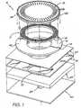
- Fig. 1there is illustrated an exploded perspective view illustrating the construction of a single ink jet nozzle 4 in accordance with the principles of the present invention.
- the nozzle 4operates on the principle of electro-mechanical energy conversion and comprises a solenoid 11 which is connected electrically at a first end 12 to a magnetic plate 13 which is in turn connected to a current source e.g. 14 utilized to activate the ink nozzle 4.
- the magnetic plate 13can be constructed from electrically conductive iron.
- a second magnetic plunger 15is also provided, again being constructed from soft magnetic iron. Upon energizing the solenoid 11, the plunger 15 is attracted to the fixed magnetic plate 13. The plunger thereby pushes against the ink within the nozzle 4 creating a high pressure zone in the nozzle chamber 17. This causes a movement of the ink in the nozzle chamber 17 and in a first design, subsequent ejection of an ink drop.
- a series of apertures e.g. 20is provided so that ink in the region of solenoid 11 is squirted out of the holes 20 in the top of the plunger 15 as it moves towards lower plate 13. This prevents ink trapped in the area of solenoid 11 from increasing the pressure on the plunger 15 and thereby increasing the magnetic forces needed to move the plunger 15.
- Fig. 2there is illustrated 30 a timing diagram of the plunger current control signal.
- the solenoid currentis activated 31 for the movement of the plunger and ejection of a drop from the ink nozzle.
- the current to the solenoidis turned off.
- a reverse currentis applied having approximately half the magnitude of the forward current.
- the reverse current 32causes the plunger to move backwards towards its original position.
- a series of torsional springs 22, 23(Fig. 1) also assists in the return of the plunger to its original position.
- a meniscus at the nozzle tipis formed with an approximately a concave hemispherical surface.
- the surface tensionwill exert a net forward force on the ink which will result in nozzle refilling.
- the repetition rate of the nozzle 4is therefore principally determined by the nozzle refill time which will be 100micro- seconds, depending on the device geometry, ink surface tension and the volume of the ejected drop.
- Fig. 3an important aspect of the operation of the eteetro-magnetically driven print nozzle will now be described.
- the plate 15Upon a current flowing through the coil 11, the plate 15 becomes strongly attracted to the plate 13.
- the plate 15experiences a downward force and begins movement towards the plate 13. This movement imparts a momentum to the ink within the nozzle chamber 17.
- the inkis subsequently ejected as hereinbefore described.
- the movement of the plate 15causes a build-up of pressure in the area 64 between the plate 15 and the coil 11. This build-up would normally result in a reduced effectiveness of the plate 15 in ejecting ink.
- the plate 15preferably includes a series of apertures e.g. 20 which allow for the flow of ink from the area 64 back into the ink chamber and thereby allow a reduction in the pressure in area 64. This results in an increased effectiveness in the operation of the plate 15.
- the apertures 20are of a teardrop shape increasing in diameter with increasing radial distance of the plunger.
- the aperture profilethereby providing minimal disturbance of the magnetic flux through the plunger while maintaining structural integrity of plunger 15.
- the current through coil 11is reversed resulting in a repulsion of the two plates 13, 15. Additionally, the torsional spring e.g. 23 acts to return the plate 15 to its initial position.
- a torsional spring e.g. 23has a number of substantial benefits including a compact layout, and the construction of the torsional spring from the same material and same processing steps as that of the plate 15.
- the top surface of plate 15does not include a series of apertures. Rather, the inner radial surface 25 of plate 15 comprises slots of substantially constant cross-sectional profile in fluid communication between the nozzle chamber 17 and the area 64 between plate 15 and the solenoid 11.
- the plate 15Upon activation of the coil 11, the plate 15 is attracted to the armature plate 13 and experiences a force directed towards plate 13.
- fluid in the area 64is compressed and experiences a higher pressure than its surrounds.
- the flow of fluidtakes place out of the slots in the inner radial surface 25 plate 15 into the nozzle chamber 17.
- the flow of fluid into chamber 17, in addition to the movement of the plate 15,causes the ejection of ink out of the ink nozzle port 24.
- the movement of the plate 15causes the torsional springs, for example 23, to be resiliently deformed.
- the coil 11is deactivated and a slight reverse current is applied.
- the reverse currentacts to repel the plate 15 from the armature plate 13.
- the torsional springs, for example 23,act as additional means to return the plate 15 to its initial or quiescent position.
- the nozzle apparatusis constructed from the following main parts including a nozzle tip 40 having an aperture 24 which can be constructed from boron doped silicon.
- the radius of the aperture 24 of the nozzle tipis an important determinant of drop velocity and drop size.
- CMOS silicon layer 42is provided upon which is fabricated all the data storage and driving circuitry 41 necessary for the operation of the nozzle 4.
- a nozzle chamber 17is also constructed.
- the nozzle chamber 17should be wide enough so that viscous drag from the chamber walls does not significantly increase the force required of the plunger. It should also be deep enough so that any air ingested through the nozzle port 24 when the plunger returns to its quiescent state does not extend to the plunger device. If it does, the ingested bubble may form a cylindrical surface instead of a hemispherical surface resulting in the nozzle not refilling properly.
- a CMOS dielectric and insulating layer containing various current paths parts for the current connection to the plunger deviceis also provided 44.
- a fixed plate of ferroelectric materialhaving two parts 13, 46.
- the two parts 13, 46are electrically insulated from one another.
- a solenoid 11is provided.
- Thiscan comprise a spiral coil of deposited copper.
- Preferably a single spiral layeris utilized to avoid fabrication difficulty and copper is used for a low resistivity and high electro-migration resistance.
- a plunger 15 of ferromagnetic materialis provided to maximize the magnetic form generated.
- the plunger 15 and fixed magnetic plate 13,46surround the solenoid 11 as a torus. Thus, little magnetic flux is lost and the flux is concentrated around the gap between the plunger 15 and the fix plate 13, 46.
- the gap between the fixed plate 13, 46 and the plunger 15is one of the most important "parts" of the print nozzle 4.
- the size of the gapwill strongly affect the magnetic force generated, and also limits the travel of the plunger 15.
- a small gapis desirable to achieve a strong magnetic force, but a large gap is desirable to allow longer plunger 15 to travel, and therefore allow smaller plunger radius to be utilized.
- the springs, e.g. 22, 23 for returning to the plunger 15 to its quiescent position after a drop has been ejectedare provided.
- the springs, e.g. 22, 23can be fabricated from the same material, and in the same processing steps, as the plunger 15.
- the springs, e.g. 22, 23act as torsional springs in their interaction with the plunger 15.
- passivation layerswhich may be silicon nitride (Si 3 N 4 ), diamond like carbon (DLC), or other chemically inert, highly impermeable layer.
- the passivation layersare especially important for device lifetime, as the active device will be immersed in the ink.
- the presently disclosed ink jet printing technologyis potentially suited to a wide range of printing system including: colour and monochrome office printers, short run digital printers, high speed digital printers, offset press supplemental printers, low cost scanning printers high speed pagewidth printers, notebook computers with inbuilt pagewidth printers, portable colour and monochrome printers, colour and monochrome copiers, colour and monochrome facsimile machines, combined printer, facsimile and copying machines, label printers, large format plotters, photograph copiers, printers for digital photographic "minilabs", video printers.
- the embodiments of the inventionuse an ink jet printer type device. Of course many different devices could be used. However presently popular ink jet printing technologies are unlikely to be suitable.
- thermal inkjetThe most significant problem with thermal inkjet is power consumption. This is approximately 100 times that required for high speed, and stems from the energy-inefficient means of drop ejection. This involves the rapid boiling of water to produce a vapor bubble which expels the ink. Water has a very high heat capacity, and must be superheated in thermal inkjet applications. This leads to an efficiency of around 0.02%, from electricity input to drop momentum (and increased surface area) out.
- piezoelectric inkjetThe most significant problem with piezoelectric inkjet is size and cost. Piezoelectric crystals have a very small deflection at reasonable drive voltages, and therefore require a large area for each nozzle. Also, each piezoelectric actuator must be connected to its drive circuit on a separate substrate. This is not a significant problem at the current limit of around 300 nozzles per print head, but is a major impediment to the fabrication of pagewide print heads with 19,200 nozzles.
- the inkjet technologies usedmeet the stringent requirements of in-camera digital color printing and other high quality, high speed, low cost printing applications.
- new inkjet technologieshave been created.
- the target featuresinclude:
- inkjet designs shown hereare suitable for a wide range of digital printing systems, from battery powered one-time use digital cameras, through to desktop and network printers, and through to commercial printing systems
- the print headis designed to be a monolithic 0.5 micron CMOS chip with MEMS post processing.
- the print headis 100 mm long, with a width which depends upon the inkjet type.
- the smallest print head designedis IJ38, which is 0.35 mm wide, giving a chip area of 35 square mm.
- the print headseach contain 19,200 nozzles plus data and control circuitry.
- Inkis supplied to the back of the print head by injection molded plastic ink channels.
- the moldingrequires 50 micron features, which can be created using a lithographically micromachined insert in a standard injection molding tool.
- Inkflows through holes etched through the wafer to the nozzle chambers fabricated on the front surface of the wafer.
- the print headis connected to the camera circuitry by tape automated bonding.
- Actuator mechanism(18 types) Basic operation mode (7 types) Auxiliary mechanism (8 types) Actuator amplification or modification method (17 types) Actuator motion (19 types) Nozzle refill method (4 types) Method of restricting back-flow through inlet (10 types) Nozzle clearing method (9 types) Nozzle plate construction (9 types) Drop ejection direction (5 types) Ink type (7 types)
- inkjet configurationscan readily be derived from these 45 examples by substituting alternative configurations along one or more of the 11 axes.
- Most of the IJ01 to IJ45 examplescan be made into inkjet print heads with characteristics superior to any currently available inkjet technology.
- Suitable applicationsinclude: Home printers, Office network printers, Short run digital printers, Commercial print systems. Fabric printers, Pocket printers, Internet WWW printers, Video printers, Medical imaging, Wide format printers, notebook PC printers. Fax machines, Industrial printing systems, Photocopiers, Photographic minilabs etc.
- Actuator mechanism(applied only to selected ink drops)
- Actuator MechanismDescription Advantages Disadvantages Examples Thermal bubble An electrothermal heater heats the ink to above boiling point, transferring significant heat to the aqueous ink. A bubble nucleates and quickly forms, expelling the ink. The efficiency of the process is low, with typically less than 0.05% of the electrical energy being transformed into kinetic energy of the drop.
- Perovskite materialssuch as tin modified lead lanthanum zirconate titanate (PLZSnT) exhibit large strains of up to 1% associated with the AFE to FE phase transition.
- ⁇ Low power consumption⁇ Many ink types can be used ⁇ Fast operation ( ⁇ 1 ⁇ s) ⁇ Relatively high longitudinal, strain ⁇ High efficiency ⁇ Electric field strength of around 3 V/ ⁇ m can be readily provided ⁇ Difficult to integrate with electronics ⁇ Unusual materials such as PLZSnT are required ⁇ Actuators require a large area ⁇ IJ04 Electrostatic plates Conductive plates are separated by a compressible or fluid dielectric (usually air).
- the conductive platesmay be in a comb or honeycomb structure, or stacked to increase the surface area and therefore the force.
- Low power consumption⁇ Many ink types can be used ⁇
- Fast operation⁇ Difficult to operate electrostatic devices in an aqueous environment ⁇
- the electrostatic actuatorwill normally need to be separated from the ink ⁇
- Very large area required to achieve high forces⁇
- High voltage drive transistorsmay be required ⁇
- Full pagewidth print headsare not competitive due to actuator size ⁇ IJ02, IJ04 Electrostatic pull on ink A strong electric field is applied to the ink, whereupon electrostatic attraction accelerates the ink towards the print medium.
- Examplesare: Samarium Cobalt (SaCo) and magnetic materials in the neodymium iron boron family (NdFeB, NdDyFeBNb, NdDyFeB, etc) ⁇ Low power consumption ⁇ Many ink types can be used ⁇ Fast operation ⁇ High efficiency ⁇ Easy extension from single nozzles to pagewidth print heads ⁇ Complex fabrication ⁇ Permanent magnetic material such as Neodymium Iron Boron (NdFeB) required.
- SaCoSamarium Cobalt
- NdDyFeBNbneodymium iron boron family
- NdDyFeBneodymium iron boron family
- NdFeBNeodymium Iron Boron
- the actuatorshould be pre-stressed to approx. 8 MPa.
- Many ink typescan be used ⁇ Fast operation ⁇ Easy extension from single nozzles to pagewidth print heads ⁇ High force is available ⁇ Force acts as a twisting motion ⁇ Unusual materials such as Terfenol-D are required ⁇ High local currents required ⁇ Copper metalization should be used for long electromigration lifetime and low resistivity ⁇ Pre-stressing may be required ⁇ Fischenbeck, USP 4,032,929 ⁇ IJ25 Surface tension reduction Ink under positive pressure is held in a nozzle by surface tension. The surface tension of the ink is reduced below the bubble threshold, causing the ink to egress from the nozzle.
- a viscosity reductioncan be achieved electrothermally with most inks, but special inks can be engineered for a 100:1 viscosity reduction, ⁇ Simple construction ⁇ No unusual materials required in fabrication ⁇ Easy extension from single nozzles to pagewidth print heads ⁇ Requires supplementary force to effect drop separation ⁇ Requires special ink viscosity properties ⁇ High speed is difficult to achieve ⁇ Requires oscillating ink pressure ⁇ A high temperature difference (typically 80 degrees) is required ⁇ Silverbrook, EP 0771 658 A2 and related patent applications Acoustic An acoustic wave is generated and focussed upon the drop ejection region.
- a heater fabricated from a conductive materialis incorporated.
- a 50 ⁇ m long PTFE bend actuator with polysilicon heater and 15 mW power inputcan provide 180 ⁇ N force and 10 ⁇ m deflection.
- Actuator motionsinclude: 1) Bend 2) Push 3) Buckle 4) Rotate ⁇ High force can be generated ⁇ PTFE is a candidate for low dielectric constant insulation in ULSI ⁇ Very low power consumption ⁇ Many ink types can be used ⁇ Simple planar fabrication ⁇ Small chip area required for each actuator ⁇ Fast operation ⁇ High efficiency ⁇ CMOS compatible voltages and currents ⁇ Easy extension from single nozzles to pagewidth print heads ⁇ Requires special material (e.g.
- PTFERequires a PTFE deposition process, which is not yet standard in ULSI fabs ⁇ PTFE deposition cannot be followed with high temperature (above 350 °C) processing ⁇ Pigmented inks may be infeasible, as pigment particles may jam the bend actuator ⁇ IJ09, IJ17, IJ18, IJ20 ⁇ IJ21, IJ22, IJ23, IJ24 ⁇ IJ27, IJ28, IJ29, IJ30 ⁇ IJ31, IJ42, IJ43, IJ44 Conductive polymer thermoelastic actuator A polymer with a high coefficient of thermal expansion (such as PTFE) is doped with conducting substances to increase its conductivity to about 3 orders of magnitude below that of copper.
- the conducting polymerexpands when resistively heated.
- conducting dopantsinclude: 1) Carbon nanotubes 2) Metal fibers 3) Conductive polymers such as doped polythiophene 4) Carbon granules ⁇ High force can be generated ⁇ Very low power consumption ⁇ Many ink types can be used ⁇ Simple planar fabrication ⁇ Small chip area required for each actuator ⁇ Fast operation ⁇ High efficiency ⁇ CMOS compatible voltages and currents ⁇ Easy extension from single nozzles to pagewidth print heads ⁇ Requires special materials development (High CTE conductive polymer) ⁇ Requires a PTFE deposition process, which is not yet standard in ULSI fabs ⁇ PTFE deposition cannot be followed with high temperature (above 350 °C) processing ⁇ Evaporation and CVD deposition techniques cannot be used ⁇ Pigmented inks may be infeasible, as pigment particles may jam the bend actuator ⁇ IJ24 Shape memory alloy A shape memory alloy such as TiNi (also known as Nitinol
- Linear Magnetic Actuator Linear magnetic actuatorsinclude the Linear Induction Actuator (LIA), Linear Permanent Magnet Synchronous Actuator (LPMSA), Linear Reluctance Synchronous Actuator (LRSA), Linear Switched Reluctance Actuator (LSRA), and the Linear Step
- Linear Magnetic actuatorscan be constructed with high thrust, long travel, and high efficiency using planar semiconductor fabrication techniques ⁇ Long actuator travel is available ⁇ Medium force is ⁇ Low voltage operation ⁇ Requires unusual semiconductor materials such as soft magnetic alloys (e.g. CoNiFe [1]) ⁇ Some varieties also require permanent magnetic materials such as Neodymium iron boron (NdFeB) ⁇ Requires complex multi-phase drive circuitry ⁇ High current operation ⁇ IJ12
- Actuatordirectly pushes Ink This is the simplest mode of operation: the actuator directly supplies sufficient kinetic energy to expel the drop. The drop must have a sufficient velocity to overcome the surface tension. ⁇ Simple operation ⁇ No external fields required ⁇ Satellite drops can be avoided if drop velocity is less than 4 m/s ⁇ Can be efficient, depending upon the actuator used ⁇ Drop repetition rate is usually limited to less than 10 KHz.
- Satellite dropsusually form if drop velocity is greater than 4.5 m/s ⁇
- the drops to be printedare selected by some manner (e.g.
- Very simple print head fabricationcan be used ⁇
- the drop selection meansdoes not need to provide the energy required to separate the drop from the nozzle ⁇
- Electrostatic field for small nozzle sizesis above air breakdown ⁇
- Electrostatic fieldmay attract dust ⁇
- Silverbrook, EP 0771 658 A2 and related patent applications⁇ Tone-Jet Magnetic pull on ink
- the drops to be printedare selected by some manner (e.g. thermally induced surface tension reduction of pressurized ink). Selected drops are separated from the ink in the nozzle by a strong magnetic field acting on the magnetic ink.
- Very simple print head fabricationcan be used ⁇
- the drop selection meansdoes not need to provide the energy required to separate the drop from the nozzle ⁇
- Requires magnetic ink⁇
- Ink colors other than blackare difficult ⁇
- Requires very high magnetic fields⁇
- Silverbrook, EP 0771 658 A2 and related patent applications ShutterThe actuator moves a shutter to block ink flow to the nozzle.
- the ink pressureis pulsed at a multiple of the drop ejection frequency.
- Actuators with small travelcan be used
- Actuators with small forcecan be used
- High speed (>50 KHz) operationcan be achieved
- Moving partsare required
- Requires ink pressure modulator⁇ Friction and wear must be considered
- Stictionis possible
- Pulsed magnetic pull on ink pusherA pulsed magnetic field attracts an 'ink pusher' at the drop ejection frequency.
- An actuatorcontrols a catch, which prevents the ink pusher from moving when a drop is not to be ejected.
- Extremely low energy operationis possible
- No heat dissipation problems⁇ Requires an external pulsed magnetic field
- Requires special materials for both the actuator and the ink pusher⁇ Complex construction ⁇ IJ10
- the ink pressure oscillationmay be achieved by vibrating the print head, or preferably by an actuator in the ink supply.
- ⁇ Oscillating ink pressurecan provide a refill pulse, allowing higher operating speed ⁇
- the actuatorsmay operate with much lower energy ⁇
- Acoustic lensescan be used to focus the sound on the nozzles ⁇
- Requires external ink pressure oscillator⁇
- Ink pressure phase and amplitudemust be carefully controlled ⁇ Acoustic reflections in the ink chamber must be designed for ⁇ Silverbrook, EP 0771 658 A2 and related patent applications ⁇ IJ08, IJ13, IJ15, IJ17 ⁇ IJ18, IJ19, IJ21 Media proximity The print head is placed in close proximity to the print medium.
- the actuatordirectly drives the drop ejection process.
- Operational simplicity⁇ Many actuator mechanisms have insufficient travel, or insufficient force, to efficiently drive the drop ejection process ⁇
- Thermal Bubble Inkjet⁇ IJ01, IJ02, IJ06, IJ07 ⁇ IJ16, IJ25, IJ26
- Differential expansion bend actuatorAn actuator material expands more on one side than on the other. The expansion may be thermal, piezoelectric, magnetostrictive, or other mechanism.
- the bend actuatorconverts a high force low travel actuator mechanism to high travel, lower force mechanism.
- Transient bend actuatorA trilayer bend actuator where the two outside layers are identical. This cancels bend due to ambient temperature and residual stress. The actuator only responds to transient heating of one side or the other.
- Actuator forcesmay not add linearly, reducing efficiency ⁇ IJ12, IJ13, IJ18, IJ20 ⁇ IJ22, IJ28, IJ42, IJ43 Linear Spring
- a linear springis used to transform a motion with small travel and high force into a longer travel, lower force motion.
- Matches low travel actuator with higher travel requirements⁇
- Non-contact method of motion transformation⁇ Requires print head area for the spring
- IJ15Reverse spring The actuator loads a spring. When the actuator is turned off, the spring releases. This can reverse the force/distance curve of the actuator to make it compatible with the force/time requirements of the drop ejection.
- the catcheither enables or disables movement of an ink pusher that is controlled In a bulk manner.
- Very low actuator energy⁇ Very small actuator size ⁇ Complex construction ⁇ Requires external force ⁇ Unsuitable for pigmented inks ⁇ IJ10 Buckle plate
- a buckle platecan be used to change a slow actuator into a fast motion. It can also convert a high force, low travel actuator into a high travel, medium force motion.
- Very fast movement achievable ⁇Must stay within elastic limits of the materials for long device life ⁇ High stresses involved ⁇ Generally high power requirement ⁇ S. Hirata et al, "An Ink-jet Head ", Proc. IEEE MEMS, Feb. 1996, pp 418-423.
- IJ18, IJ27 Tapered magnetic poleA tapered magnetic pole can increase travel at the expense of force.
- ⁇Linearizes the magnetic force/distance curve ⁇ Complex construction ⁇ IJ14 Lever A lever and fulcrum is used to transform a motion with small travel and high force into a motion with longer travel and lower force. The lever can also reverse the direction of travel.
- a small angular deflection of the actuatorresults in a rotation of the impeller vanes, which push the ink against stationary vanes and out of the nozzle.
- ⁇ High mechanical advantage⁇
- the ratio of force to travel of the actuatorcan be matched to the nozzle requirements by varying the number of impeller vanes ⁇
- Complex construction⁇
- Unsuitable for pigmented inks ⁇ IJ28 Acoustic lensA refractive or diffractive (e.g. zone plate) acoustic lens is used to concentrate sound waves.
- Actuator motion Description AdvantagesDisadvantages: Volume expansion
- the volume of the actuatorchanges, pushing the ink in all directions.
- ⁇ Simple construction in the case of thermal ink jet⁇ High energy is typically required to achieve volume expansion. This leads to thermal stress, cavitation, and kogation in thermal ink jet implementations ⁇ Hewlett-Packard Thermal Inkjet ⁇ Canon Bubblejet Linear, normal to chip surface
- the actuatormoves in a direction normal to the print head surface.
- the nozzleis typically in the line of movement.
- the effective area of the actuatorbecomes the membrane area ⁇ Fabrication complexity ⁇ Actuator size ⁇ Difficulty of integration in a VLSI process ⁇ 1982 Howkins USP 4,459,601 Rotary
- the actuatorcauses the rotation of some element, such a grill or impeller ⁇ Rotary levers may be used to increase travel ⁇ Small chip area requirements ⁇
- Device complexity ⁇May have friction at a pivot point ⁇ IJ05, IJ08, IJ13, IJ28 Bend The actuator bends when energized. This may be due to differential thermal expansion, piezoelectric expansion, magnetostriction, or other form of relative dimensional change. ⁇ A very small change in dimensions can be converted to a large motion.
- the actuator⁇ Requires the actuator to be made from at least two distinct layers, or to have a thermal difference across the actuator ⁇ 1970 Kyser et al USP 3,946,398 ⁇ 1973 Stemme USP 3,747,120 ⁇ IJ03, IJ09, IJ10, IJ19 ⁇ IJ23, IJ24, IJ25, U29 ⁇ IJ30, IJ31, IJ33, IJ34 ⁇ IJ35 Swivel
- the actuatorswivels around a central pivot. This motion is suitable where there are opposite forces applied to opposite sides of the paddle, e.g. Lorenz force.
- Nozzle refill methodDescription Advantages Disadvantages Examples Surface tension After the actuator is energized, it typically returns rapidly to its normal position. This rapid return sucks in air through the nozzle opening. The ink surface tension at the nozzle then exerts a small force restoring the meniscus to a minimum area.
- a filteris located between the ink inlet and the nozzle chamber.
- the filterhas a multitude of small holes or slots, restricting ink flow.
- the filteralso removes particles which may block the nozzle.
- ⁇ Additional advantage of ink filtration ⁇ Ink filtermay be fabricated with no additional process steps ⁇ Restricts refill rate ⁇ May result in complex construction ⁇ IJ04, IJ12, IJ24, IJ27 ⁇ IJ29, IJ30 Small inlet compared to nozzle The ink inlet channel to the nozzle chamber has a substantially smaller cross section than that of the nozzle, resulting in easier ink egress out of the nozzle than out of the inlet. ⁇ Design simplicity ⁇ Restricts refill rate ⁇ May result in a relatively large chip area ⁇ Only partially effective ⁇ IJ02, IJ37, IJ44 Inlet shutter A secondary actuator controls the position of a shutter, closing off the ink inlet when the main actuator is energized.
- Nozzle Clearing methodDescription Advantages Disadvantages Examples Normal nozzle firing All of the nozzles are fired periodically, before the ink has a chance to dry. When not in use the nozzles are sealed (capped) against air. The nozzle firing is usually performed during a special clearing cycle, after first moving the print head to a cleaning station.
- ⁇ A high nozzle clearing capabilitycan be achieved ⁇ May be implemented at very low cost in systems which already include acoustic actuators ⁇ High implementation cost if system does not already include an acoustic actuator ⁇ IJ08, IJ13, IJ15, IJ17 ⁇ IJ18, IJ19, IJ21 Nozzle clearing plate A microfabricated plate is pushed against the nozzles. The plate has a post for every nozzle.
- the bladeis usually fabricated from a flexible polymer, e.g. rubber or synthetic elastomer.
- ⁇ Effective for planar print head surfaces⁇ Low cost ⁇ Difficult to use if print head surface is non-planar or very fragile ⁇ Requires mechanical parts ⁇ Blade can wear out in high volume print systems ⁇ Many ink jet systems Separate Ink boiling heater A separate heater is provided at the nozzle although the normal drop e-ection mechanism does not require it. The heaters do not require individual drive circuits, as many nozzles can be cleared simultaneously, and no imaging is required.
- ⁇ Can be effective where other nozzle clearing methods cannot be used⁇ Can be implemented at no additional cost in some inkjet configurations ⁇ Fabrication complexity ⁇ Can be used with many IJ series ink jets
- Nozzle plate constructionDescription Advantages Disadvantages Examples Electroformed nickel A nozzle plate is separately fabricated from electroformed nickel, and bonded to the print head chip. ⁇ Fabrication simplicity ⁇ High temperatures and pressures are required to bond nozzle plate ⁇ Minimum thickness constraints ⁇ Differential thermal expansion ⁇ Hewlett Packard Thermal Inkjet Laser ablated or drilled polymer Individual nozzle holes are ablated by an intense UV laser in a nozzle plate, which is typically a polymer such as polyimide or polysulphone ⁇ No masks required ⁇ Can be quite fast ⁇ Some control over nozzle profile is possible ⁇ Equipment required is relatively low cost ⁇ Each hole must be individually formed ⁇ Special equipment required ⁇ Slow where there are many thousands of nozzles per print head ⁇ May produce thin burrs at exit holes ⁇ Canon Bubblejet ⁇ 1988 Sercel et al., SPIE, Vol.
- Nozzle chambersare etched in the front of the wafer, and the wafer is thinned from the back side. Nozzles are then etched in the etch stop layer.
- High accuracy ( ⁇ 1 ⁇ m)⁇ Monolithic ⁇ Low cost ⁇ No differential expansion ⁇ Requires long etch times ⁇ Requires a support wafer ⁇ IJ03, IJ05, IJ06, IJ07 ⁇ IJ08, IJ09, IJ10, IJ13 ⁇ IJ14, IJ15, IJ16, IJ19 ⁇ IJ21, IJ23, IJ25, IJ26 No nozzle plate Various methods have been tried to eliminate the nozzles entirely, to prevent nozzle clogging.
- EdgeInk flow is along the surface of the chip, and ink drops are ejected from the chip edge.
- Simple construction⁇ No silicon etching required ⁇ Good heat sinking via substrate ⁇ Mechanically strong ⁇ Ease of chip handing ⁇ Nozzles limited to edge ⁇ High resolution is difficult ⁇
- Fast color printingrequires one print head per color ⁇ Canon Bubblejet 1979 Endo et al GB patent 2,007,162 ⁇ Xerox heater-in-pit 1990 Hawkins et al USP 4,899,181 ⁇ Tone-jet Surface ('roof shooter') Ink flow is along the surface of the chip, and ink drops are ejected from the chip surface, normal to the plane of the chip.
- Suitable for piezoelectric print headsrequire several thousand connections to drive circuits ⁇ Cannot be manufactured in standard CMOS fabs ⁇ Complex assembly required ⁇ Epson Stylus ⁇ Tektronix hot melt piezoelectric ink jets
- Aqueous, dye Water based inkwhich typically contains: water, dye, surfactant, humectant, and biocide.
- Modern ink dyeshave high water-fastness, light fastness ⁇ Environmentally friendly ⁇ No odor ⁇ Slow drying ⁇ Corrosive ⁇ Bleeds on paper ⁇ May strikethrough ⁇ Cockles paper ⁇
- Most existing inkjets⁇ All IJ series ink jets ⁇ Silverbrook, EP 0771 658 A2 and related patent applications
- Aqueous, pigment Water based inkwhich typically contains: water, pigment, surfactant, humectant, and biocide. Pigments have an advantage in reduced bleed, wicking and strikethrough.
Landscapes
- Engineering & Computer Science (AREA)
- Manufacturing & Machinery (AREA)
- Particle Formation And Scattering Control In Inkjet Printers (AREA)
- Ink Jet (AREA)
Abstract
Description
- The present invention relates to the field of ink jet printing systems.
- Many different types of printing have been invented, a large number of which are presently in use. The known forms of print have a variety of methods for marking the print media with a relevant marking media. Commonly used forms of printing include offset printing, laser printing and copying devices, dot matrix type impact printers, thermal paper printers, film recorders, thermal wax printers, dye sublimation printers and ink jet printers both of the drop on demand and continuous flow type. Each type of printer has its own advantages and problems when considering cost, speed, quality, reliability, simplicity of construction and operation etc.
- In recent years, the field of ink jet printing, wherein each individual pixel of ink is derived from one or more ink nozzles has become increasingly popular primarily due to its inexpensive and versatile nature.
- Many different techniques of ink jet printing have been invented. For a survey of the field. reference is made to an article by J Moore, "Non-Impact Printing: Introduction and Historical Perspective", Output Hard Copy Devices, Editors R Dubeck and S Sherr, pages 207-220 (1988).
- Ink jet printers themselves come in many different types. The utilisation of a continuous stream ink in ink jet printing appears to date back to at least 1929 wherein US Patent No. 1941001 by Hansell discloses a simple form of continuous stream electro-static inkjet printing.
- US Patent 3596275 by Sweet also discloses a process of a continuous ink jet printing including the step wherein the ink jet stream is modulated by a high frequency electro-static field so as to cause drop separation. This technique is still utilized by several manufacturers including Elmjet and Scitex (see also US Patent No. 3373437 by Sweet et al)
- Piezo-electric ink jet printers are also one form of commonly utilized ink jet printing device. Piezo-electric systems are disclosed by Kyser et. al. in US Patent No. 3946398 (1970) which utilises a diaphragm mode of operation, by Zolten in US Patent 3683212 (1970) which discloses a squeeze mode of operation of a piezo electric crystal, Stemme in US Patent No. 3747120 (1972) discloses a bend mode of piezo-electric operation, Howkins in US Patent No. 4459601 discloses a Piezo electric push mode actuation of the ink jet stream and Fischbeck in US 4584590 which discloses a sheer mode type of piezo-electric transducer element.
- Document JP-A-4126255 shows an ink jet printhead with a plurality of nozzle arrangements each such arrangement comprising a plunger, and an electric coil located adjacent to the plunger and electrically connected to a nozzle activation signal wherein upon activation of the activation signal, said plunger is caused by said coil to move from an ink loaded position to an ink ejection position thereby causing the ejection of ink from said ink ejection port.
- Recently, thermal ink jet printing has become an extremely popular form of ink jet printing. The ink jet printing techniques include those disclosed by Endo et al in GB 2007162 (1979) and Vaught et al in US Patent 4490728. Both the aforementioned references disclosed ink jet printing techniques rely upon the activation of an electrothermal actuator which results in the creation of a bubble in a constricted space, such as a nozzle, which thereby causes the ejection of ink from an aperture connected to the confined space onto a relevant print media. Printing devices utilising the electro-thermal actuator are manufactured by manufacturers such as Canon and Hewlett Packard.
- As can be seen from the foregoing, many different types of printing technologies are available. Ideally, a printing technology should have a number of desirable attributes. These include inexpensive construction and operation, high speed operation, safe and continuous long term operation etc. Each technology may have its own advantages and disadvantages in the areas of cost, speed, quality, reliability, power usage, simplicity of construction operation, durability and consumables.
- Many inkjet printing mechanisms are known. Unfortunately, in mass production techniques, the production of ink jet heads is quite difficult. For example, often, the orifice or nozzle plate is constructed separately from the ink supply and ink ejection mechanism and bonded to the mechanism at a later stage (Hewlett-Packard Journal, Vol. 36 no 5, pp33-37 (1985)). These separate material processing steps required in handling such precision devices often adds a substantially expense in manufacturing.
- Additionally, side shooting ink jet technologies (U.S. Patent No. 4,899,181) are often used but again, this limit the amount of mass production throughput given any particular capital investment.
- Additionally, more esoteric techniques are also often utilized. These can include electroforming of nickel stage (Hewlett-Packard Journal, Vol. 36 no 5, pp33-37 (1985)), electro-discharge machining, laser ablation (U.S. Patent No. 5,208,604), micro-punching, etc.
- The utilisation of the above techniques is likely to add substantial expense to the mass production of ink jet print heads and therefore add substantially to their final cost.
- It would therefore be desirable if an efficient system for the mass production of ink jet print heads could be developed.
- It is an object of the present invention to provide for an ink jet printing mechanism having a series of ink ejection nozzles, with the nozzles including an internal selective actuator mechanism activated on a nozzle by nozzle basis by the placement of a field around said nozzles. Accordingly the invention provides a printhead according to claim 1. Advantageous embodiments are provided in the dependent claims.
- Notwithstanding any other forms which may fall within the scope of the present invention, preferred forms of the invention will now be described, by way of example only, with reference to the accompanying drawings in which:
- Fig. 1 is an exploded perspective view illustrating the construction of a single ink jet nozzle in accordance with an embodiment of the present invention;
- Fig. 2 is a timing diagram illustrating the operation of an embodiment;
- Fig. 3 is a cross-seedonat top view of a single ink nozzle constructed in accordance with an embodiment of the present invention;
- Fig. 4 provides a legend of the materials indicated in Fig. 5 to Fig. 21;
- Fig. 5 to Fig. 21 illustrate sectional views of the manufacturing steps in one form of construction of an ink jet printhead nozzle;
- In Fig. 1, there is illustrated an exploded perspective view illustrating the construction of a single
ink jet nozzle 4 in accordance with the principles of the present invention. - The
nozzle 4 operates on the principle of electro-mechanical energy conversion and comprises asolenoid 11 which is connected electrically at afirst end 12 to amagnetic plate 13 which is in turn connected to a current source e.g. 14 utilized to activate theink nozzle 4. Themagnetic plate 13 can be constructed from electrically conductive iron. - A second
magnetic plunger 15 is also provided, again being constructed from soft magnetic iron. Upon energizing thesolenoid 11, theplunger 15 is attracted to the fixedmagnetic plate 13. The plunger thereby pushes against the ink within thenozzle 4 creating a high pressure zone in thenozzle chamber 17. This causes a movement of the ink in thenozzle chamber 17 and in a first design, subsequent ejection of an ink drop. A series of apertures e.g. 20 is provided so that ink in the region ofsolenoid 11 is squirted out of the holes 20 in the top of theplunger 15 as it moves towardslower plate 13. This prevents ink trapped in the area ofsolenoid 11 from increasing the pressure on theplunger 15 and thereby increasing the magnetic forces needed to move theplunger 15. - Referring now to Fig. 2, there is illustrated 30 a timing diagram of the plunger current control signal. Initially, the solenoid current is activated 31 for the movement of the plunger and ejection of a drop from the ink nozzle. After approximately 2 micro-seconds, the current to the solenoid is turned off. At the same time or at a slightly
later time 32, a reverse current is applied having approximately half the magnitude of the forward current. As the plunger has a residual magnetism, thereverse current 32 causes the plunger to move backwards towards its original position. A series oftorsional springs 22, 23 (Fig. 1) also assists in the return of the plunger to its original position. The reverse current is turned off before the magnetism of theplunger 15 is reversed which would otherwise result in the plunger being attracted to the fixed plate again. Returning to Fig. I, the forced return of theplunger 15 to its quiescent position results in a low pressure in thechamber 17. This can cause ink to begin flowing from theoutlet nozzle 24 inwards and also ingests air to thechamber 17. The forward velocity of the drop and the backward velocity of the ink in thechamber 17 are resolved by the ink drop breaking off around thenozzle 24. The ink drop then continues to travel toward the recording medium under its own momentum. The nozzle refills due to the surface tension of the ink at thenozzle tip 24. Shortly after the time of drop break off, a meniscus at the nozzle tip is formed with an approximately a concave hemispherical surface. The surface tension will exert a net forward force on the ink which will result in nozzle refilling. The repetition rate of thenozzle 4 is therefore principally determined by the nozzle refill time which will be 100micro- seconds, depending on the device geometry, ink surface tension and the volume of the ejected drop. - Turning now to Fig. 3, an important aspect of the operation of the eteetro-magnetically driven print nozzle will now be described. Upon a current flowing through the
coil 11, theplate 15 becomes strongly attracted to theplate 13. Theplate 15 experiences a downward force and begins movement towards theplate 13. This movement imparts a momentum to the ink within thenozzle chamber 17. The ink is subsequently ejected as hereinbefore described. Unfortunately, the movement of theplate 15 causes a build-up of pressure in thearea 64 between theplate 15 and thecoil 11. This build-up would normally result in a reduced effectiveness of theplate 15 in ejecting ink. - However, in a first design the
plate 15 preferably includes a series of apertures e.g. 20 which allow for the flow of ink from thearea 64 back into the ink chamber and thereby allow a reduction in the pressure inarea 64. This results in an increased effectiveness in the operation of theplate 15. - Preferably, the apertures 20 are of a teardrop shape increasing in diameter with increasing radial distance of the plunger. The aperture profile thereby providing minimal disturbance of the magnetic flux through the plunger while maintaining structural integrity of
plunger 15. - After the
plunger 15 has reached its end position, the current throughcoil 11 is reversed resulting in a repulsion of the twoplates plate 15 to its initial position. - The use of a torsional spring e.g. 23 has a number of substantial benefits including a compact layout, and the construction of the torsional spring from the same material and same processing steps as that of the
plate 15. - In an alternative design, the top surface of
plate 15 does not include a series of apertures. Rather, the inner radial surface 25 ofplate 15 comprises slots of substantially constant cross-sectional profile in fluid communication between thenozzle chamber 17 and thearea 64 betweenplate 15 and thesolenoid 11. Upon activation of thecoil 11, theplate 15 is attracted to thearmature plate 13 and experiences a force directed towardsplate 13. As a result of the movement, fluid in thearea 64 is compressed and experiences a higher pressure than its surrounds. As a result, the flow of fluid takes place out of the slots in the inner radial surface 25plate 15 into thenozzle chamber 17. The flow of fluid intochamber 17, in addition to the movement of theplate 15, causes the ejection of ink out of theink nozzle port 24. Again, the movement of theplate 15 causes the torsional springs, for example 23, to be resiliently deformed. Upon completion of the movement of theplate 15, thecoil 11 is deactivated and a slight reverse current is applied. The reverse current acts to repel theplate 15 from thearmature plate 13. The torsional springs, for example 23, act as additional means to return theplate 15 to its initial or quiescent position. - Returning now to Fig. 1, the nozzle apparatus is constructed from the following main parts including a
nozzle tip 40 having anaperture 24 which can be constructed from boron doped silicon. The radius of theaperture 24 of the nozzle tip is an important determinant of drop velocity and drop size. - Next, a
CMOS silicon layer 42 is provided upon which is fabricated all the data storage and driving circuitry 41 necessary for the operation of thenozzle 4. In this layer anozzle chamber 17 is also constructed. Thenozzle chamber 17 should be wide enough so that viscous drag from the chamber walls does not significantly increase the force required of the plunger. It should also be deep enough so that any air ingested through thenozzle port 24 when the plunger returns to its quiescent state does not extend to the plunger device. If it does, the ingested bubble may form a cylindrical surface instead of a hemispherical surface resulting in the nozzle not refilling properly. A CMOS dielectric and insulating layer containing various current paths parts for the current connection to the plunger device is also provided 44. - Next, a fixed plate of ferroelectric material is provided having two
parts parts - Next, a
solenoid 11 is provided. This can comprise a spiral coil of deposited copper. Preferably a single spiral layer is utilized to avoid fabrication difficulty and copper is used for a low resistivity and high electro-migration resistance. - Next, a
plunger 15 of ferromagnetic material is provided to maximize the magnetic form generated. Theplunger 15 and fixedmagnetic plate solenoid 11 as a torus. Thus, little magnetic flux is lost and the flux is concentrated around the gap between theplunger 15 and thefix plate - The gap between the fixed
plate plunger 15 is one of the most important "parts" of theprint nozzle 4. The size of the gap will strongly affect the magnetic force generated, and also limits the travel of theplunger 15. A small gap is desirable to achieve a strong magnetic force, but a large gap is desirable to allowlonger plunger 15 to travel, and therefore allow smaller plunger radius to be utilized. - Next, the springs, e.g. 22, 23 for returning to the
plunger 15 to its quiescent position after a drop has been ejected are provided. The springs, e.g. 22, 23 can be fabricated from the same material, and in the same processing steps, as theplunger 15. Preferably the springs, e.g. 22, 23 act as torsional springs in their interaction with theplunger 15. - Finally, all surfaces are coated with passivation layers, which may be silicon nitride (Si3N4), diamond like carbon (DLC), or other chemically inert, highly impermeable layer. The passivation layers are especially important for device lifetime, as the active device will be immersed in the ink.
- One form of detailed manufacturing process which can be used to fabricate monolithic ink jet print heads operating in accordance with the principles taught by the present embodiment can proceed utilizing the following steps:
- 1. Using a double sided polished wafer deposit 3 microns of epitaxial silicon heavily doped with boron.
- 2. Deposit 10 microns of epitaxial silicon, either p-type or n-type, depending upon the CMOS process used.
- 3. Complete a 0.5 micron, one poly, 2 metal CMOS process. This step is shown in Fig. 5. For clarity, these diagrams may not be to scale, and may not represent a cross section though any single plane of the nozzle. Fig. 4 is a key to representations of various materials in these manufacturing diagrams, and those of other cross referenced ink jet configurations.
- 4. Etch the CMOS oxide layers down to silicon or aluminum using Mask 1. This mask defines the nozzle chamber, the edges of the print heads chips, and the vias for the contacts from the aluminum electrodes to the two halves of the split fixed magnetic plate.
- 5. Plasma etch the silicon down to the boron doped buried layer, using oxide from
step 4 as a mask. This etch does not substantially etch the aluminum. This step is shown in Fig. 6. - 6. Deposit a seed layer of cobalt nickel iron alloy. CoNiFe is chosen due to a high saturation flux density of 2 Tesla, and a low coercivity. [Osaka, Tetsuya et al, A soft magnetic CoNiFe film with high saturation magnetic flux density, Nature 392, 796-798 (1998)].
- 7. Spin on 4 microns of resist, expose with Mask 2, and develop. This mask defines the split fixed magnetic plate, for which the resist acts as an electroplating mold. This step is shown in Fig. 7.
- 8. Electroplate 3 microns of CoNiFe. This step is shown in Fig. 8.
- 9. Strip the resist and etch the exposed seed layer. This step is shown in Fig. 9.
- 10. Deposit 0.1 microns of silicon nitride (Si3N4)·
- 11. Etch the nitride layer using Mask 3. This mask defines the contact vias from each end of the solenoid coil to the two halves of the split fixed magnetic plate.
- 12. Deposit a seed layer of copper. Copper is used for its low resistivity (which results in higher efficiency) and its high electromigration resistance, which increases reliability at high current densities.
- 13. Spin on 5 microns of resist, expose with
Mask 4, and develop. This mask defines the solenoid spiral coil and the spring posts, for which the resist acts as an electroplating mold. This step is shown in Fig. 10. - 14.
Electroplate 4 microns of copper. - 15. Strip the resist and etch the exposed copper seed layer. This step is shown in Fig. 11.
- 16. Wafer probe. All electrical connections are complete at this point, bond pads are accessible, and the chips are not yet separated.
- 17. Deposit 0.1 microns of silicon nitride.
- 18. Deposit 1 micron of sacrificial material. This layer determines the magnetic gap.
- 19. Etch the sacrificial material using Mask 5. This mask defines the spring posts. This step is shown in Fig. 12.
- 20. Deposit a seed layer of CoNiFe.
- 21. Spin on 4.5 microns of resist, expose with Mask 6, and develop. This mask defines the walls of the magnetic plunger, plus the spring posts. The resist forms an electroplating mold for these parts. This step is shown in Fig. 13.
- 22.
Electroplate 4 microns of CoNiFe. This step is shown in Fig. 14. - 23. Deposit a seed layer of CoNiFe.
- 24. Spin on 4 microns of resist, expose with Mask 7, and develop. This mask defines the roof of the magnetic plunger, the springs, and the spring posts. The resist forms an electroplating mold for these parts. This step is shown in Fig. 15.
- 25. Electroplate 3 microns of CoNiFe. This step is shown in Fig. 16.
- 26. Mount the wafer on a glass blank and back-etch the wafer using KOH, with no mask. This etch thins the wafer and stops at the buried boron doped silicon layer. This step is shown in Fig. 17.
- 27. Plasma back-etch the boron doped silicon layer to a depth of (approx.) 1 micron using Mask 8. This mask defines the nozzle rim. This step is shown in Fig. 18.
- 28. Plasma back-etch through the boron doped layer using Mask 9. This mask defines the nozzle, and the edge of the chips. At this stage, the chips are separate, but are still mounted on the glass blank. This step is shown in Fig. 19.
- 29. Detach the chips from the glass blank. Strip all adhesive, resist, sacrificial, and exposed seed layers. This step is shown in Fig. 20.
- 30. Mount the print heads in their packaging, which may be a molded plastic former incorporating ink channels which supply different colors of ink to the appropriate regions of the front surface of the wafer.
- 31. Connect the print heads to their interconnect systems.
- 32. Hydrophobize the front surface of the print heads.
- 33. Fill the completed print heads with ink and test them. A filled nozzle is shown in Fig. 21.
- The presently disclosed ink jet printing technology is potentially suited to a wide range of printing system including: colour and monochrome office printers, short run digital printers, high speed digital printers, offset press supplemental printers, low cost scanning printers high speed pagewidth printers, notebook computers with inbuilt pagewidth printers, portable colour and monochrome printers, colour and monochrome copiers, colour and monochrome facsimile machines, combined printer, facsimile and copying machines, label printers, large format plotters, photograph copiers, printers for digital photographic "minilabs", video printers. PhotoCD printers, portable printers for PDAs, wallpaper printers, indoor sign printers, billboard printers, fabric printers, camera printers and fault tolerant commercial printer arrays.
- The embodiments of the invention use an ink jet printer type device. Of course many different devices could be used. However presently popular ink jet printing technologies are unlikely to be suitable.
- The most significant problem with thermal inkjet is power consumption. This is approximately 100 times that required for high speed, and stems from the energy-inefficient means of drop ejection. This involves the rapid boiling of water to produce a vapor bubble which expels the ink. Water has a very high heat capacity, and must be superheated in thermal inkjet applications. This leads to an efficiency of around 0.02%, from electricity input to drop momentum (and increased surface area) out.
- The most significant problem with piezoelectric inkjet is size and cost. Piezoelectric crystals have a very small deflection at reasonable drive voltages, and therefore require a large area for each nozzle. Also, each piezoelectric actuator must be connected to its drive circuit on a separate substrate. This is not a significant problem at the current limit of around 300 nozzles per print head, but is a major impediment to the fabrication of pagewide print heads with 19,200 nozzles.
- Ideally, the inkjet technologies used meet the stringent requirements of in-camera digital color printing and other high quality, high speed, low cost printing applications. To meet the requirements of digital photography, new inkjet technologies have been created. The target features include:
- low power (less than 10 Watts)
- high resolution capability (1,600 dpi or more)
- photographic quality output
- low manufacturing cost
- small size (pagewidth times minimum cross section)
- high speed (< 2 seconds per page).
- All of these features can be met or exceeded by the inkjet systems described below with differing levels of difficulty. 45 different inkjet technologies have been developed by the Assignee to give a wide range of choices for high volume manufacture. These technologies form part of separate applications assigned to the present Assignee as set out in the table below.
- The inkjet designs shown here are suitable for a wide range of digital printing systems, from battery powered one-time use digital cameras, through to desktop and network printers, and through to commercial printing systems
- For ease of manufacture using standard process equipment, the print head is designed to be a monolithic 0.5 micron CMOS chip with MEMS post processing. For color photographic applications, the print head is 100 mm long, with a width which depends upon the inkjet type. The smallest print head designed is IJ38, which is 0.35 mm wide, giving a chip area of 35 square mm. The print heads each contain 19,200 nozzles plus data and control circuitry.
- Ink is supplied to the back of the print head by injection molded plastic ink channels. The molding requires 50 micron features, which can be created using a lithographically micromachined insert in a standard injection molding tool. Ink flows through holes etched through the wafer to the nozzle chambers fabricated on the front surface of the wafer. The print head is connected to the camera circuitry by tape automated bonding.
- The following table is a guide to cross-referenced patent applications filed concurrently herewith and discussed hereinafter with the reference being utilized in subsequent tables when referring to a particular case:
Docket No. Reference Title IJJ01US IJ01 Radiant Plunger Ink Jet Printer IJ02US IJ02 Electrostatic: Ink Jet Printer IJ03US IJ03 Planar Thermoelastic Bend Actuator Ink Jet IJ04US IJ04 Stacked Electrostatic Ink Jet Printer IJ05US IJ05 Reverse Spring Lever Ink Jet Printer IJ06US IJ06 Paddle Type Ink Jet Printer IJ07US IJ07 Permanent Magnet Electromagnetic Ink Jet Printer IJ08US IJ08 Planar Swing Grill Electromagnetic Ink Jet Printer IJ09US IJ09 Pump Action Refill Ink Jet Printer IJ10US IJ10 Pulsed Magnetic Field Ink Jet Printer IJ11US IJ11 Two Plate Reverse Firing Electromagnetic Ink Jet Printer IJ12US IJ12 Linear Stepper Actuator Ink Jet Printer IJ13US IJ13 Gear Driven Shutter Ink Jet Printer IJ14US IJ14 Tapered Magnetic Pole Electromagnetic Ink Jet Printer IJ15US IJ15 Linear Spring Electromagnetic Grill Ink Jet Printer IJ16US IJ16 Lorenz Diaphragm Electromagnetic Ink Jet Printer IJ17US IJ17 PTFE Surface Shooting Shuttered Oscillating Pressure Ink Jet Printer IJ18US IJ18 Buckle Grip Oscillating Pressure Ink Jet Printer IJ19US IJ19 Shutter Based Ink Jet Printer IJ20US IJ20 Curling Calyx Thermoelastic Ink Jet Printer IJ21US IJ21 Thermal Actuated Ink Jet Printer IJ22US IJ22 Iris Motion Ink Jet Printer IJ23US IJ23 Direct Firing Thermal Bend Actuator Ink Jet Printer IJ24US IJ24 Conductive PTFE Ben Activator Vented Ink Jet Printer IJ25US IJ25 Magnetostrictive Ink Jet Printer IJ26US IJ26 Shape Memory Alloy Ink Jet Printer IJ27US IJ27 Buckle Plate Ink Jet Printer IJ28US IJ28 Thermal Elastic Rotary Impeller Ink Jet Printer IJ29US IJ29 Thermoelastic Bend Actuator Ink Jet Printer IJ30US IJ30 Thermoelastic Bend Actuator Using PTFE and Corrugated Copper Ink Jet Printer IJ31US IJ31 Bead Actuator Direct Ink Supply Ink Jet Printer IJ32US IJ32 A High Young's Modulus Thermoelastic Ink Jet Printer IJ33US IJ33 Thermally actuated slotted chamber wall ink jet printer IJ34US IJ34 Ink Jet Printer having a thermal actuator comprising an external coiled spring IJ35US IJ35 Trough Container Ink Jet Printer IJ36US IJ36 Dual Chamber Single Vertical Actuator Ink Jet IJ37US IJ37 Dual Nozzle Single Horizontal Fulcrum Actuator Ink Jet IJ38US IJ38 Dual Nozzle Single Horizontal Actuator Ink Jet IJ39US IJ39 A single bend actuator cupped paddle ink jet printing device IJ40US IJ40 A thermally actuated ink jet printer having a series of thermal actuator units IJ41US IJ41 A thermally actuated ink jet printer including a tapered heater element IJ42US IJ42 Radial Back-Curling Thermoelastic ink Jet IJ43US IJ43 Inverted Radial Back-Curling Thermoelastic Ink Jet IJ44US IJ44 Surface bend actuator vented ink supply ink jet printer IJ45US IJ45 Coil Actuated Magnetic Plate Ink Jet Printer - Eleven important characteristics of the fundamental operation of individual inkjet nozzles have been identified. These characteristics are largely orthogonal and so can be elucidated as an eleven dimensional matrix. Most of the eleven axes of this matrix include entries developed by the present assignee.
- The following tables form the axes of an eleven dimensional table of inkjet types.
Actuator mechanism (18 types)
Basic operation mode (7 types)
Auxiliary mechanism (8 types)
Actuator amplification or modification method (17 types)
Actuator motion (19 types)
Nozzle refill method (4 types)
Method of restricting back-flow through inlet (10 types)
Nozzle clearing method (9 types)
Nozzle plate construction (9 types)
Drop ejection direction (5 types)
Ink type (7 types) - The complete eleven dimensional table represented by these axes contains 36.9 billion possible configurations of inkjet nozzle. While not all of the possible combinations result in a viable inkjet technology, many million configurations are viable. It is clearly impractical to elucidate all of the possible configurations. Instead, certain inkjet types have been investigated in detail. These are designated IJ01 to IJ45 above.
- Other inkjet configurations can readily be derived from these 45 examples by substituting alternative configurations along one or more of the 11 axes. Most of the IJ01 to IJ45 examples can be made into inkjet print heads with characteristics superior to any currently available inkjet technology.
- Where there are prior art examples known to the inventor, one or more of these examples are listed in the examples column of the tables below. The IJ01 to IJ45 series are also listed in the examples column. In some cases, a printer may be listed more than once in a table, where it shares characteristics with more than one entry.
- Suitable applications include: Home printers, Office network printers, Short run digital printers, Commercial print systems. Fabric printers, Pocket printers, Internet WWW printers, Video printers, Medical imaging, Wide format printers, Notebook PC printers. Fax machines, Industrial printing systems, Photocopiers, Photographic minilabs etc.
- The information associated with the aforementioned 11 dimensional matrix are set out in the following tables.
Actuator Mechanism Description Advantages Disadvantages Examples Thermal bubble An electrothermal heater heats the ink to above boiling point, transferring significant heat to the aqueous ink. A bubble nucleates and quickly forms, expelling the ink.
The efficiency of the process is low, with typically less than 0.05% of the electrical energy being transformed into kinetic energy of the drop.◆ Simple construction
◆ No moving parts
◆ Fast operation
◆ Small chip area required for actuator◆ High temperatures required
◆ High mechanical stress
◆ Unusual materials required
◆ Large drive transistors
◆ Cavitation causes actuator failure
◆ Kogation reduces bubble formation
◆ Large print heads are difficult to fabricate◆ Canon Bubblejet 1979 Endo et al GB patent 2,007,162
◆ Xerox heater-in-pit 1990 Hawkins et al USP 4,899,181
◆Hewlett-Packard TIJ 1982 Vaught et al USP 4,490,728Piezoelectric A piezoelectric crystal such as lead lanthanum zirconate (PZT) is electrically activated, and either expands, shears, or bends to apply pressure to the ink, ejecting drops. ◆ Low power consumption
◆ Many ink types can be used
◆ Fast operation
◆ High efficiency◆ Very large area required for actuator
◆ Difficult to integrate with electronics
◆ High voltage drive transistors required
◆ Full pagewidth print heads impractical due to actuator size
◆ Requires electrical poling in high field strengths during manufacture◆ Kyser et al USP 3,946,398
◆ Zoltan USP 3,683,212
◆ 1973 Stemme USP 3,747,120
◆ Epson Stylus
◆ Tektronix
◆ IJ04Electro-strlctive An electric field is used to activate electrostriction in relaxor materials such as lead lanthanum zirconate titanate (PLZT) or lead magnesium niobate (PMN). ◆ Low power consumption
◆ Many ink types can be used
◆ Low thermal expansion
◆ Electric field strength required (approx. 3.5 V/µm) can be generated without difficulty
◆ Does not require electrical poling◆ Low maximum strain (approx. 0.01%)
◆ Large area required for actuator due to low strain
◆ Response speed is marginal (~10 µs)
◆ High voltage drive transistors required
◆ Full pagewidth print heads impractical due to actuator size◆ Seiko Epson, Usui et all JP 253401/96
◆ IJ04Ferroelectric An electric field is used to induce a phase transition between the antiferroelectric (AFE) and ferroelectric (FE) phase.
Perovskite materials such as tin modified lead lanthanum zirconate titanate (PLZSnT) exhibit large strains of up to 1% associated with the AFE to FE phase transition.◆ Low power consumption
◆ Many ink types can be used
◆ Fast operation (< 1 µs)
◆ Relatively high longitudinal, strain
◆ High efficiency
◆ Electric field strength of around 3 V/µm can be readily provided◆ Difficult to integrate with electronics
◆ Unusual materials such as PLZSnT are required
◆ Actuators require a large area◆ IJ04 Electrostatic plates Conductive plates are separated by a compressible or fluid dielectric (usually air). Upon application of a voltage, the plates attract each other and displace ink, causing drop ejection. The conductive plates may be in a comb or honeycomb structure, or stacked to increase the surface area and therefore the force. ◆ Low power consumption
◆ Many ink types can be used
◆ Fast operation◆ Difficult to operate electrostatic devices in an aqueous environment
◆ The electrostatic actuator will normally need to be separated from the ink
◆ Very large area required to achieve high forces
◆ High voltage drive transistors may be required
◆ Full pagewidth print heads are not competitive due to actuator size◆ IJ02, IJ04 Electrostatic pull on ink A strong electric field is applied to the ink, whereupon electrostatic attraction accelerates the ink towards the print medium. ◆ Low current consumption
◆ Low temperature◆ High voltage required ◆ May be damaged by sparks due to air breakdown
◆ Required field strength increases as the drop size decreases
◆ High voltage drive transistors required
◆ Electrostatic field attracts dust◆ 1989 Salto et al, USP 4,799,068
◆ 1989 Miura et al, USP 4,810,954
◆ Tone-jetPermanent magnet electro-magnetic An electromagnet directly attracts a permanent magnet, displacing ink and causing drop ejection. Rare earth magnets with a field strength around 1 Tesla can be used. Examples are: Samarium Cobalt (SaCo) and magnetic materials in the neodymium iron boron family (NdFeB, NdDyFeBNb, NdDyFeB, etc) ◆ Low power consumption
◆ Many ink types can be used
◆ Fast operation
◆ High efficiency
◆ Easy extension from single nozzles to pagewidth print heads◆ Complex fabrication
◆ Permanent magnetic material such as Neodymium Iron Boron (NdFeB) required.
◆ High local currents required
◆ Copper metalization should be used for long electromigration lifetime and low resistivity
◆ Pigmented inks are usually infeasible
◆ Operating temperature limited to the Curie temperature (around 540 K)◆ IJ07, IJ10 Soft magnetic core electro-magnetic A solenoid induced a magnetic field in a soft magnetic core or yoke fabricated from a ferrous material such as electroplated iron alloys such as CoNiFe [1], CoFe, or NiFe alloys. Typically, the soft magnetic material is in two parts, which are normally held apart by a spring. When the solenoid is actuated, the two parts attract, displacing the ink. ◆ Low power consumption
◆ Many ink types can be used
◆ Fast operation
◆ High efficiency
◆ Easy extension from single nozzles to pagewidth print heads◆ Complex fabrication
◆ Materials not usually present in a CMOS fab such as NiFe, CoNiFe, or CoFe are required
◆ High local currents required
◆ Copper metalization should be used for long electromigration lifetime and low resistivity
◆ Electroplating is required
◆ High saturation flux density is required (2.0-2.1 T is achievable with CoNiFe [1])◆ IJ01, IJ05, IJ08, IJ10
◆ IJ12, IJ14, IJ15, IJ17Magnetic Lorenz force The Lorenz force acting on a current carrying wire in a magnetic field is utilized.
This allows the magnetic field to be supplied externally to the print head, for example with rare earth permanent magnets.
Only the current carrying wire need be fabricated on the print-head, simplifying materials requirements.◆ Low power consumption
◆ Many ink types can be used
◆ Fast operation
◆ High local currents required
◆ Easy extension from single nozzles to pagewidth print heads
◆ Pigmented inks are usually infeasible◆ Force acts as a twisting motion
◆ Typically, only a quarter of the solenoid length provides force in a useful direction
◆ High efficiency
◆Copper metalization should be used for long electromigration lifetime and low resistivity◆ IJ06, IJ11, IJ13, IJ16 Magneto-striction The actuator uses the giant magnetostrictive effect of materials such as Terfenol-D (an alloy of terbium, dysprosium and iron developed at the Naval Ordnance Laboratory, hence Ter-Fe-NOL). For best efficiency, the actuator should be pre-stressed to approx. 8 MPa. ◆ Many ink types can be used
◆ Fast operation
◆ Easy extension from single nozzles to pagewidth print heads
◆ High force is available◆ Force acts as a twisting motion
◆ Unusual materials such as Terfenol-D are required
◆ High local currents required
◆ Copper metalization should be used for long electromigration lifetime and low resistivity
◆ Pre-stressing may be required◆ Fischenbeck, USP 4,032,929
◆ IJ25Surface tension reduction Ink under positive pressure is held in a nozzle by surface tension. The surface tension of the ink is reduced below the bubble threshold, causing the ink to egress from the nozzle. ◆ Low power consumption
◆ Simple construction
◆ No unusual materials required in fabrication
◆ High efficiency
◆ Easy extension from single nozzles to pagewidth print heads◆ Requires supplementary force to ettect drop separation
◆ Requires special ink surfactants
◆ Speed may be limited by surfactant properties◆ Silverbrook, EP 0771 658 A2 and related patent applications Viscosity reduction The ink viscosity is locally reduced to select which drops are to be ejected. A viscosity reduction can be achieved electrothermally with most inks, but special inks can be engineered for a 100:1 viscosity reduction, ◆ Simple construction
◆ No unusual materials required in fabrication
◆ Easy extension from single nozzles to pagewidth print heads◆Requires supplementary force to effect drop separation
◆ Requires special ink viscosity properties
◆ High speed is difficult to achieve
◆ Requires oscillating ink pressure
◆ A high temperature difference (typically 80 degrees) is required◆ Silverbrook, EP 0771 658 A2 and related patent applications Acoustic An acoustic wave is generated and focussed upon the drop ejection region. ◆ Can operate without a nozzle plate ◆ Complex drive circuitry
◆ Complex fabrication
◆ Low efficiency
◆ Poor control of drop position
◆ Poor control of drop volume◆ 1993 Hadimioglu et al, EUP 550,192
◆ 1993 Elrod et al, EUP 572,220Thermoelastic bend actuator An actuator which relies upon differential thermal expansion upon Joule heating is used. ◆ Low power consumption
◆ Many ink types can be used
◆ Simple planar fabrication
◆ Small chip area required for each actuator
◆ Fast operation
◆ High efficiency
◆ CMOS compatible voltages and currents
◆ Standard MEMS processes can be used
◆ Easy extension from single nozzles to pagewidth print heads◆ Efficient aqueous operation requires a thermal insulator on the hot side
◆ Corrosion prevention can be difficult
◆ Pigmented inks may be infeasible, as pigment particles may jam the bend actuator◆IJ03, IJ09, IJ17, IJ18
◆IJ19, IJ20, IJ21, IJ22
◆IJ23, IJ24, IJ27, IJ28
◆IJ29, IJ30, IJ31, IJ32
◆IJ33, IJ34, IJ35, IJ36
◆IJ37, IJ38, IJ39, IJ40
◆IJ41High CTE thermoelastic actuator A material with a very high coefficient of thermal expansion (CTE) such as polytetrafluoroethylene (PTFE) is used. As high CTE materials are usually non-conductive, a heater fabricated from a conductive material is incorporated. A 50 µ m long PTFE bend actuator with polysilicon heater and 15 mW power input can provide 180 µN force and 10 µm deflection. Actuator motions include:
1) Bend
2) Push
3) Buckle
4) Rotate◆ High force can be generated
◆ PTFE is a candidate for low dielectric constant insulation in ULSI
◆ Very low power consumption
◆ Many ink types can be used
◆ Simple planar fabrication
◆ Small chip area required for each actuator
◆ Fast operation
◆ High efficiency
◆ CMOS compatible voltages and currents
◆ Easy extension from single nozzles to pagewidth print heads◆ Requires special material (e.g. PTFE)
◆ Requires a PTFE deposition process, which is not yet standard in ULSI fabs
◆ PTFE deposition cannot be followed with high temperature (above 350 °C) processing
◆ Pigmented inks may be infeasible, as pigment particles may jam the bend actuator◆ IJ09, IJ17, IJ18, IJ20
◆ IJ21, IJ22, IJ23, IJ24
◆ IJ27, IJ28, IJ29, IJ30
◆ IJ31, IJ42, IJ43, IJ44Conductive polymer thermoelastic actuator A polymer with a high coefficient of thermal expansion (such as PTFE) is doped with conducting substances to increase its conductivity to about 3 orders of magnitude below that of copper. The conducting polymer expands when resistively heated.
Examples of conducting dopants include:
1) Carbon nanotubes
2) Metal fibers
3) Conductive polymers such as doped polythiophene
4) Carbon granules◆ High force can be generated
◆ Very low power consumption
◆ Many ink types can be used
◆ Simple planar fabrication
◆ Small chip area required for each actuator
◆ Fast operation
◆ High efficiency
◆ CMOS compatible voltages and currents
◆ Easy extension from single nozzles to pagewidth print heads◆ Requires special materials development (High CTE conductive polymer)
◆ Requires a PTFE deposition process, which is not yet standard in ULSI fabs
◆ PTFE deposition cannot be followed with high temperature (above 350 °C) processing
◆ Evaporation and CVD deposition techniques cannot be used
◆ Pigmented inks may be infeasible, as pigment particles may jam the bend actuator◆ IJ24 Shape memory alloy A shape memory alloy such as TiNi (also known as Nitinol - Nickel Titanium alloy developed at the Naval Ordnance Laboratory) is thermally switched between its weak martensitic state and its high stiffness austenic state. The shape of the actuator in its martensitic state is deformed relative to The austenic shape. The shape change causes ejection of a drop. ◆ High force is available (stresses of hundreds of MPa)
◆ Large strain is available (more than 3%)
◆ High corrosion resistance
◆ Simple construction
◆ Easy extension from single nozzles to pagewidth print heads
◆ Low voltage operation◆ Fatigue limits maximum number of cycles
◆ Low strain (1%) is required to extend fatigue resistance
◆ Cycle rate limited by heat removal
◆ Requires unusual materials (TiNi)
◆ The latent heat of transformation must be provided
◆ High current operation
◆ Requires pre-stressing to distort the martensitic state◆ IJ26 Linear Magnetic Actuator Linear magnetic actuators include the Linear Induction Actuator (LIA), Linear Permanent Magnet Synchronous Actuator (LPMSA), Linear Reluctance Synchronous Actuator (LRSA), Linear Switched Reluctance Actuator (LSRA), and the Linear Stepper Actuator (LSA). ◆ Linear Magnetic actuators can be constructed with high thrust, long travel, and high efficiency using planar semiconductor fabrication techniques
◆ Long actuator travel is available
◆ Medium force is
◆ Low voltage operation◆ Requires unusual semiconductor materials such as soft magnetic alloys (e.g. CoNiFe [1])
◆ Some varieties also require permanent magnetic materials such as Neodymium iron boron (NdFeB)
◆ Requires complex multi-phase drive circuitry
◆ High current operation◆IJ12 Operational mode Description Advantages Disadvantages Examples Actuator directly pushes Ink This is the simplest mode of operation: the actuator directly supplies sufficient kinetic energy to expel the drop. The drop must have a sufficient velocity to overcome the surface tension. ◆ Simple operation ◆ No external fields required
◆ Satellite drops can be avoided if drop velocity is less than 4 m/s
◆ Can be efficient, depending upon the actuator used◆ Drop repetition rate is usually limited to less than 10 KHz. However, this is not fundamental to the method, but is related to the refill method normally used
◆All of the drop kinetic energy must be provided by the actuator
◆ Satellite drops usually form if drop velocity is greater than 4.5 m/s◆ Thermal inkjet
◆ Piezoelectric inkjet
◆ IJ01, IJ02, IJ03, IJ04
◆ IJ05, IJ06, IJ07, IJ09
◆ IJ11, IJ12, IJ14, IJ16
◆ IJ20, IJ22, IJ23, IJ24
◆ IJ25, IJ26, IJ27, IJ28
◆ IJ29, IJ30, IJ31, IJ32
◆ IJ33, IJ34, IJ35, IJ36
◆ IJ37, IJ38, IJ39, IJ40
◆ IJ41, IJ42, IJ43, IJ44Proximity The drops to be printed are selected by some manner (e.g. thermally induced surface tension reduction of pressurized ink). Selected drops are separated from the ink in the nozzle by contact with the print medium or a transfer roller. ◆ Very simple print head fabrication can be used
◆ The drop selection means does not need to provide the energy required to separate the drop from the nozzle◆ Requires close proximity between the print head and the print media or transfer roller
◆ May require two print heads printing alternate rows of the image
◆ Monolithic color print heads are difficult◆ Silverbrook, EP 0771 658 A2 and related patent applications Electrostatic pull on ink The drops to be printed are selected by some manner (e.g. thermally induced surface tension reduction of pressurized ink). Selected drops are separated from the ink in the nozzle by a strong electric field. ◆ Very simple print head fabrication can be used
◆ The drop selection means does not need to provide the energy required to separate the drop from the nozzle◆ Requires very high electrostatic field
◆ Electrostatic field for small nozzle sizes is above air breakdown
◆ Electrostatic field may attract dust◆ Silverbrook, EP 0771 658 A2 and related patent applications
◆ Tone-JetMagnetic pull on ink The drops to be printed are selected by some manner (e.g. thermally induced surface tension reduction of pressurized ink). Selected drops are separated from the ink in the nozzle by a strong magnetic field acting on the magnetic ink. ◆ Very simple print head fabrication can be used
◆ The drop selection means does not need to provide the energy required to separate the drop from the nozzle◆ Requires magnetic ink
◆ Ink colors other than black are difficult
◆ Requires very high magnetic fields◆ Silverbrook, EP 0771 658 A2 and related patent applications Shutter The actuator moves a shutter to block ink flow to the nozzle. The ink pressure is pulsed at a multiple of the drop ejection frequency. ◆High speed (>50 KHz) operation can be achieved due to reduced refill time
◆ Drop timing can be very accurate
◆ The actuator energy can be very low◆ Moving parts are required
◆ Requires ink pressure modulator
◆ Friction and wear must be considered
◆ Stiction is possible◆ IJ13, IJ17, IJ21 Shuttered grill The actuator moves a shutter to block ink flow through a grill to the nozzle. The shutter movement need only be equal to the width of the grill holes. ◆ Actuators with small travel can be used
◆ Actuators with small force can be used
◆ High speed (>50 KHz) operation can be achieved◆ Moving parts are required
◆ Requires ink pressure modulator
◆ Friction and wear must be considered
◆ Stiction is possible◆ IJ08, IJ15, IJ18, IJ19 Pulsed magnetic pull on ink pusher A pulsed magnetic field attracts an 'ink pusher' at the drop ejection frequency. An actuator controls a catch, which prevents the ink pusher from moving when a drop is not to be ejected. ◆ Extremely low energy operation is possible
◆ No heat dissipation problems◆ Requires an external pulsed magnetic field
◆ Requires special materials for both the actuator and the ink pusher
◆ Complex construction◆ IJ10 Auxiliary Mechanism Description Advantages Disadvantages Examples None The actuator directly fires the ink drop, and there is no external field or other mechanism required. ◆ Simplicity of construction
◆ Simplicity of operation
◆ Small physical size◆ Drop ejection energy must be supplied by individual nozzle actuator ◆ Most inkjets, including piezoelectric and thermal bubble.
◆ IJ01-IJ07, IJ09, IJ11
◆ IJ12, IJ14, IJ20, IJ22
◆ IJ23-IJ45Oscillating ink pressure (including acoustic stimulation) The ink pressure oscillates, providing much of the drop ejection energy. The actuator selects which drops are to be fired by selectively blocking or enabling nozzles. The ink pressure oscillation may be achieved by vibrating the print head, or preferably by an actuator in the ink supply. ◆ Oscillating ink pressure can provide a refill pulse, allowing higher operating speed
◆ The actuators may operate with much lower energy
◆ Acoustic lenses can be used to focus the sound on the nozzles◆ Requires external ink pressure oscillator
◆ Ink pressure phase and amplitude must be carefully controlled
◆ Acoustic reflections in the ink chamber must be designed for◆ Silverbrook, EP 0771 658 A2 and related patent applications
◆ IJ08, IJ13, IJ15, IJ17
◆ IJ18, IJ19, IJ21Media proximity The print head is placed in close proximity to the print medium. Selected drops protrude from the print head further than unselected drops, and contact the print medium. The drop soaks into the medium fast enough to cause drop separation. ◆ Low power
◆ High accuracy
◆ Simple print head construction◆ Precision assembly required
◆ Paper fibers may cause problems
◆ Cannot print on rough substrates◆ Silverbrook, EP 0771 658 A2 and related patent applications Transfer roller Drops are printed to a transfer roller instead of straight to the print medium. A transfer roller can also be used for proximity drop separation. ◆ High accuracy
◆ Wide range of print substrates can be used
◆ Ink can be dried on the transfer roller◆ Bulky
◆ Expensive
◆ Complex construction◆ Silverbrook, EP 0771 658 A2 and related patent applications
◆ Tektronix hot melt piezoelectric inkjet
◆ Any of the IJ seriesElectrostatic An electric field is used to accelerate selected drops towards the print medium. ◆ Low power
◆ Simple print head construction◆ Field strength required for separation of small drops is near or above air breakdown ◆ Silverbrook, EP 0771 658 A2 and related patent applications
◆ Tone-JetDirect magnetic field A magnetic field is used to accelerate selected drops of magnetic ink towards the print medium. ◆ Low power
◆ Simple print head construction◆ Requires magnetic ink
◆ Requires strong magnetic field◆ Silverbrook, EP 0771 658 A2 and related patent applications Cross magnetic field The print head is placed in a constant magnetic field. The Lorenz force in a current carrying wire is used to move the actuator. ◆ Does not require magnetic materials to be integrated in the print head manufacturing process ◆ Requires external magnet
◆ Current densities may be high, resulting in electromigration problems◆ IJ06, IJ16 Pulsed magnetic field A pulsed magnetic field is used to cyclically attract a paddle, which pushes on the ink. A small actuator moves a catch, which selectively prevents the paddle from moving. ◆ Very low power operation is possible
◆ Small print head size◆ Complex print head construction
◆ Magnetic materials required in print head◆ IJ10 Actuator amplification Description Advantages Disadvantages Examples None No actuator mechanical amplification is used. The actuator directly drives the drop ejection process. ◆ Operational simplicity ◆ Many actuator mechanisms have insufficient travel, or insufficient force, to efficiently drive the drop ejection process ◆ Thermal Bubble Inkjet
◆ IJ01, IJ02, IJ06, IJ07
◆ IJ16, IJ25, IJ26Differential expansion bend actuator An actuator material expands more on one side than on the other. The expansion may be thermal, piezoelectric, magnetostrictive, or other mechanism. ◆ Provides greater travel in a reduced print head area
◆ The bend actuator converts a high force low travel actuator mechanism to high travel, lower force mechanism.◆ High stresses are involved
◆ Care must be taken that the materials do not delaminate
◆ Residual bend resulting from high temperature or high stress during formation◆ Piezoelectric
◆ IJ03, IJ09, IJ17-IJ24
◆ IJ27, IJ29-IJ39, IJ42,
◆ IJ43, IJ44Transient bend actuator A trilayer bend actuator where the two outside layers are identical. This cancels bend due to ambient temperature and residual stress. The actuator only responds to transient heating of one side or the other. ◆ Very good temperature stability
◆ High speed, as a new drop can be fired before heat dissipates
◆ Cancels residual stress of formation◆ High stresses are involved
◆ Care must be taken that the materials do not delaminate◆ IJ40, IJ41 Actuator stack A series of thin actuators are stacked. This can be appropriate where actuators require high electric field strength, such as electrostatic and piezoelectric actuators. ◆ Increased travel
◆ Reduced drive voltage◆ Increased fabrication complexity
◆ Increased possibility of short circuits due to pinholes◆ Some piezoelectric ink jets
◆ IJ04Multiple actuators Multiple smaller actuators are used simultaneously to move the ink. Each actuator need provide only a portion of the force required. ◆ Increases the force available from an actuator
◆ Multiple actuators can be positioned to control ink flow accurately◆ Actuator forces may not add linearly, reducing efficiency ◆ IJ12, IJ13, IJ18, IJ20
◆ IJ22, IJ28, IJ42, IJ43Linear Spring A linear spring is used to transform a motion with small travel and high force into a longer travel, lower force motion. ◆ Matches low travel actuator with higher travel requirements
◆ Non-contact method of motion transformation◆ Requires print head area for the spring ◆ IJ15 Reverse spring The actuator loads a spring. When the actuator is turned off, the spring releases. This can reverse the force/distance curve of the actuator to make it compatible with the force/time requirements of the drop ejection. ◆ Better coupling to the ink ◆ Fabrication complexity
◆ High stress in the spring◆ IJ05, IJ11 Colled actuator A bend actuator is coiled to provide greater travel in a reduced chip area. ◆ Increases travel
◆ Reduces chip area
◆ Planar implementations are relatively easy to fabricate.◆ Generally restricted to planar implementations due to extreme fabrication difficulty in other orientations. ◆ IJ17, IJ21, U34, IJ35 Flexure bend actuator A bend actuator has a small region near the fixture point, which flexes much more readily than the remainder of the actuator.
The actuator flexing is effectively converted from an even coiling to an angular bend, resulting in greater travel of the actuator tip.◆ Simple means of increasing travel of a bend actuator ◆ Care must be taken not to exceed the elastic limit in the flexure area
◆ Stress distribution is very uneven
◆ Difficult to accurately model with finite element analysis◆ IJ10, IJ19, IJ33 Gears Gears can be used to increase travel at the expense of duration. Circular gears, rack and pinlon, ratchets, and other gearing methods can be used. ◆ Low force, low travel actuators can be used
◆ Can be fabricated using standard surface MEMS processes◆ Moving parts are required
◆ Several actuator cycles are required
◆ More complex drive electronics
◆ Complex construction
◆ Friction, friction, and wear are possible◆ IJ13 Catch The actuator controls a small catch. The catch either enables or disables movement of an ink pusher that is controlled In a bulk manner. ◆ Very low actuator energy
◆ Very small actuator size◆ Complex construction
◆ Requires external force
◆ Unsuitable for pigmented inks◆ IJ10 Buckle plate A buckle plate can be used to change a slow actuator into a fast motion. It can also convert a high force, low travel actuator into a high travel, medium force motion. ◆ Very fast movement achievable ◆ Must stay within elastic limits of the materials for long device life
◆ High stresses involved
◆ Generally high power requirement◆ S. Hirata et al, "An Ink-jet Head ...", Proc. IEEE MEMS, Feb. 1996, pp 418-423.
◆ IJ18, IJ27Tapered magnetic pole A tapered magnetic pole can increase travel at the expense of force. ◆ Linearizes the magnetic force/distance curve ◆ Complex construction ◆ IJ14 Lever A lever and fulcrum is used to transform a motion with small travel and high force into a motion with longer travel and lower force. The lever can also reverse the direction of travel. ◆ Matches low travel actuator with higher travel requirements
◆ Fulcrum area has no linear movement, and can be used for a fluid seal◆ High stress around the fulcrum ◆ IJ32, IJ36, IJ37 Rotary Impeller The actuator is connected to a rotary impeller. A small angular deflection of the actuator results in a rotation of the impeller vanes, which push the ink against stationary vanes and out of the nozzle. ◆ High mechanical advantage
◆ The ratio of force to travel of the actuator can be matched to the nozzle requirements by varying the number of impeller vanes◆ Complex construction
◆ Unsuitable for pigmented inks◆ IJ28 Acoustic lens A refractive or diffractive (e.g. zone plate) acoustic lens is used to concentrate sound waves. ◆ No moving parts ◆ Large area required
◆ Only relevant for acoustic ink jets◆ 1993 Hadimioglu et al, EUP 550,192
◆ 1993 Eirod et al, EUP 572,220Sharp conductive point A sharp point is used to concentrate an electrostatic field. ◆ Simple construction ◆ Difficult to fabricate using standard VLSI processes for a surface ejecting ink-jet
◆ Only relevant for electrostatic ink jets◆ Tone-jet Actuator motion Description Advantages Disadvantages Examples Volume expansion The volume of the actuator changes, pushing the ink in all directions. ◆ Simple construction in the case of thermal ink jet ◆ High energy is typically required to achieve volume expansion. This leads to thermal stress, cavitation, and kogation in thermal ink jet implementations ◆Hewlett-Packard Thermal Inkjet
◆ Canon BubblejetLinear, normal to chip surface The actuator moves in a direction normal to the print head surface. The nozzle is typically in the line of movement. ◆ Efficient coupling to ink drops ejected normal to the surface ◆ High fabrication complexity may be required to achieve perpendicular motion ◆ IJ01, IJ02, IJ04, IJ07
◆ IJ11, IJ14Linear, parallel to chip surface The actuator moves parallel to the print head surface. Drop ejection may still be normal to the surface. ◆ Suitable for planar fabrication ◆Fabrication complexity
◆ Friction
◆ Stiction◆ IJ12, IJ13, IJ15, IJ33,
◆ IJ34, IJ35, IJ36Membrane push An actuator with a high force but small area is used to push a stiff membrane that is in contact with the ink. ◆ The effective area of the actuator becomes the membrane area ◆Fabrication complexity
◆ Actuator size
◆ Difficulty of integration in a VLSI process◆ 1982 Howkins USP 4,459,601 Rotary The actuator causes the rotation of some element, such a grill or impeller ◆ Rotary levers may be used to increase travel
◆ Small chip area requirements◆ Device complexity
◆ May have friction at a pivot point◆ IJ05, IJ08, IJ13, IJ28 Bend The actuator bends when energized. This may be due to differential thermal expansion, piezoelectric expansion, magnetostriction, or other form of relative dimensional change. ◆ A very small change in dimensions can be converted to a large motion. ◆ Requires the actuator to be made from at least two distinct layers, or to have a thermal difference across the actuator ◆ 1970 Kyser et al USP 3,946,398
◆ 1973 Stemme USP 3,747,120
◆ IJ03, IJ09, IJ10, IJ19
◆ IJ23, IJ24, IJ25, U29
◆ IJ30, IJ31, IJ33, IJ34
◆ IJ35Swivel The actuator swivels around a central pivot. This motion is suitable where there are opposite forces applied to opposite sides of the paddle, e.g. Lorenz force. ◆ Allows operation where the net linear force on the paddle is zero
◆ Small chip area requirements◆Inefficient coupling to the ink motion ◆ IJ06 Straighten The actuator is normally bent, and straightens when energized. ◆ Can be used with shape memory alloys. where the austenic phase is planar ◆ Requires careful balance of stresses to ensure that the quiescent bend is accurate ◆ IJ26, IJ32 Double bend The actuator bends in one direction when one element is energized, and bends the other way when another element is energized. ◆ One actuator can be used to power two nozzles.
◆ Reduced chip size.
◆ Not sensitive to ambient temperature◆ Difficult to make the drops ejected by both bend directions identical.
◆ A small efficiency loss compared to equivalent single bend actuators.◆ IJ36, IJ37, IJ38 Shear Energizing the actuator causes a shear motion in the actuator material. ◆ Can increase the effective travel of piezoelectric actuators ◆Not readily applicable to other actuator mechanisms ◆ 1985 Fishbeck USP 4,584,590 Radial constriction The actuator squeezes an ink reservoir, forcing ink from a constricted nozzle. ◆ Relatively easy to fabricate single nozzles from glass tubing as macroscopic structures ◆ High force required
◆ Inefficient
◆ Difficult to integrate with VLSI processes◆ 1970 Zoltan USP 3,683,212 Coil / uncoil A coiled actuator uncoils or coils more tightly. The motion of the free end of the actuator ejects the ink. ◆ Easy to fabricate as a planar VLSI process
◆ Small area required, therefore low cost◆ Difficult to fabricate for non-planar devices
◆ Poor out-of-plane stiffness◆ IJ17, IJ21, IJ34, IJ35 Bow The actuator bows (or buckles) in the middle when energized. ◆ Can increase the speed of travel
◆ Mechanically rigid◆ Maximum travel is constrained
◆ High force required◆ IJ16, IJ18, IJ27 Push-Pull Two actuators control a shutter. One actuator pulls the shutter, and the other pushes it. ◆ The structure is pinned at both ends, so has a high out-of-plane rigidity ◆ Not readily suitable for inkjets which directly push the ink ◆ IJ18 Curl inwards A set of actuators curl inwards to reduce the volume of ink that they enclose. ◆ Good fluid flow to the region behind the actuator increases efficiency ◆ Design complexity ◆ IJ20, IJ42 Curl outwards A set of actuators curl outwards, pressurizing ink in a chamber surrounding the actuators, and expelling ink from a nozzle in the chamber. ◆ Relatively simple construction ◆ Relatively large chip area ◆ IJ43 Iris Multiple vanes enclose a volume of ink. These simultaneously rotate, reducing the volume between the vanes. ◆ High efficiency
◆ Small chip area◆ High fabrication complexity
◆ Not suitable for pigmented inks◆ IJ22 Acoustic vibration The actuator vibrates at a high frequency. ◆ The actuator can be physically distant from the ink ◆ Large area required for efficient operation at useful frequencies
◆ Acoustic coupling and crosstalk
◆ Complex drive circuitry
◆ Poor control of drop volume and position◆ 1993 Hadimioglu et al, EUP 550,192
◆ 1993 Elrod et al, EUP 572,220None In various ink jet designs the actuator does not move. ◆ No moving parts ◆ Various other tradeoffs are required to eliminate moving parts ◆ Silverbrook, EP 0771 658 A2 and related patent applications
◆ Tone-jetNozzle refill method Description Advantages Disadvantages Examples Surface tension After the actuator is energized, it typically returns rapidly to its normal position.
This rapid return sucks in air through the nozzle opening. The ink surface tension at the nozzle then exerts a small force restoring the meniscus to a minimum area.◆ Fabrication simplicity
◆ Operational simplicity◆ Low speed
◆ Surface tension force relatively small compared to actuator force
◆ Long refill time usually dominates the total repetition rate◆ Thermal inkjet
◆ Piezoelectric inkjet
◆ IJ01-IJ07, IJ10-IJ14
◆ IJ16, IJ20, IJ22-IJ45Shuttered oscillating ink pressure Ink to the nozzle chamber is provided at a pressure that oscillates at twice the drop ejection frequency. When a drop is to be ejected, the shutter is opened for 3 half cycles: drop ejection, actuator return, and refill. ◆ High speed
◆ Low actuator energy, as the actuator need only open or close the shutter, instead of ejecting the ink drop◆ Requires common ink pressure oscillator
◆ May not be suitable for pigmented inks◆ IJ08, IJ13, IJ15, IJ17
◆ IJ18, IJ19, IJ21Refill actuator After the main actuator has ejected a drop a second (refill) actuator is energized. The refill actuator pushes ink into the nozzle chamber. The refill actuator returns slowly, to prevent its return from emptying the chamber again. ◆ High speed, as the nozzle is actively refilled ◆ Requires two independent actuators per nozzle ◆ IJ09 Positive ink pressure The ink is held a slight positive pressure. After the ink drop is ejected, the nozzle chamber fills quickly as surface tension and ink pressure both operate to refill the nozzle. ◆ High refill rate, therefore a high drop repetition rate is possible ◆ Surface spill must be prevented
◆ Highly hydrophobic print head surfaces are required◆ Silverbrook, EP 0771 658 A2 and related patent applications
◆ Alternative for:
◆ IJ01-IJ07, IJ10-IJ14
◆ IJ16, IJ20, IJ22-IJ45Inlet back-How restriction method Description Advantages Disadvantages Examples Long Inlet channel The ink inlet channel to the nozzle chamber is made long and relatively narrow, relying on viscous drag to reduce inlet back-flow. ◆ Design simplicity
◆ Operational simplicity
◆ Reduces crosstalk◆ Restricts refill rate
◆ May result in a relatively large chip area
◆ Only partially effective◆ Thermal inkjet
◆ Piezoelectric inkjet
◆ IJ42, IJ43Positive ink pressure The ink is under a positive pressure, so that in the quiescent state some of the ink drop already protrudes from the nozzle.
This reduces the pressure in the nozzle chamber which is required to eject a certain volume of ink. The reduction in chamber pressure results in a reduction in ink pushed out through the inlet.◆ Drop selection and separation forces can be reduced
◆ Fast refill time◆ Requires a method (such as a nozzle rim or effective hydrophobizing, or both) to prevent flooding of the ejection surface of the print head. ◆ Silverbrook, EP 0771 658 A2 and related patent applications
◆ Possible operation of the following:
◆ IJ01-IJ07, IJ09-IJ12
◆ IJ14, IJ16, IJ20, IJ22,
◆ IJ23-IJ34, IJ36-IJ41
◆ IJ44Baffle One or more baffles are placed in the inlet ink flow. When the actuator is energized, the rapid ink movement creates eddies which restrict the flow through the inlet. The slower refill process is unrestricted, and does not result in eddies. ◆ The refill rate is not as restricted as the long inlet method.
◆ Reduces crosstalk◆ Design complexity
◆ May increase fabrication complexity (e.g. Tektronix hot melt Piezoelectric print heads).◆ HP Thermal Ink Jet
◆ Tektronix piezoelectric ink jetFlexible flap restricts inlet In this method recently disclosed by Canon, the expanding actuator (bubble) pushes on a flexible flap that restricts the inlet. ◆ Significantly reduces back-flow for edge-shooter thermal ink jet devices ◆ Not applicable to most inkjet configurations
◆ Increased fabrication complexity
◆ Inelastic deformation of polymer flap results in creep over extended use◆ Canon Inlet filter A filter is located between the ink inlet and the nozzle chamber. The filter has a multitude of small holes or slots, restricting ink flow. The filter also removes particles which may block the nozzle. ◆ Additional advantage of ink filtration
◆ Ink filter may be fabricated with no additional process steps◆ Restricts refill rate
◆ May result in complex construction◆ IJ04, IJ12, IJ24, IJ27
◆ IJ29, IJ30Small inlet compared to nozzle The ink inlet channel to the nozzle chamber has a substantially smaller cross section than that of the nozzle, resulting in easier ink egress out of the nozzle than out of the inlet. ◆ Design simplicity ◆ Restricts refill rate
◆ May result in a relatively large chip area
◆ Only partially effective◆ IJ02, IJ37, IJ44 Inlet shutter A secondary actuator controls the position of a shutter, closing off the ink inlet when the main actuator is energized. ◆ Increases speed of the ink-jet print head operation ◆ Requires separate refill actuator and drive circuit ◆ IJ09 The Inlet is located behind the Ink-pushing surface The method avoids the problem of inlet back-flow by arranging the ink-pushing surface of the actuator between the inlet and the nozzle. ◆ Back-flow problem is eliminated ◆ Requires careful design to minimize the negative pressure behind the paddle ◆ IJ01, IJ03, IJ05, IJ06
◆ IJ07, IJ10, IJ11, IJ14
◆ IJ16, IJ22, IJ23, IJ25
◆ IJ28, IJ31, IJ32, IJ33
◆ IJ34, IJ35, IJ36, IJ39
◆ IJ40, IJ41Part of the actuator moves to shut off the Inlet The actuator and a wall of the ink chamber are arranged so that the motion of the actuator closes off the inlet. ◆ Significant reductions in back-flow can be achieved
◆ Compact designs possible◆ Small increase in fabrication complexity ◆ IJ07, IJ20, IJ26, IJ38 Nozzle actuator does not result In Ink back-flow In some configurations of ink jet, there is no expansion or movement of an actuator which may cause ink back-flow through the inlet. ◆ Ink back-flow problem is eliminated ◆ None related to ink back-flow on actuation ◆ Silverbrook, EP 0771 658 A2 and related patent applications
◆ Valve-jet
◆ Tone-jet
◆ IJ08, IJ13, IJ15, IJ17.
◆ IJ18, IJ19, IJ21Nozzle Clearing method Description Advantages Disadvantages Examples Normal nozzle firing All of the nozzles are fired periodically, before the ink has a chance to dry. When not in use the nozzles are sealed (capped) against air.
The nozzle firing is usually performed during a special clearing cycle, after first moving the print head to a cleaning station.◆ No added complexity on the print head ◆ May not be sufficient to displace dried ink ◆ Most ink jet systems
◆ IJ01- IJ07, IJ09-IJ12
◆ IJ14, IJ16, IJ20, IJ22
◆ IJ23-IJ34, IJ36-IJ45Extra power to Ink heater In systems which heat the ink, but do not boil it under normal situations, nozzle clearing can be achieved by over-powering the heater and boiling ink at the nozzle. ◆ Can be highly effective if the heater is adjacent to the nozzle ◆ Requires higher drive voltage for clearing
◆ May require larger drive transistors◆ Silverbrook, EP 0771 658 A2 and related patent applications Rapid succession of actuator pulses The actuator is fired in rapid succession. In some configurations, this may cause heat build-up at the nozzle which bolls the ink, clearing the nozzle. In other situations, it may cause sufficient vibrations to dislodge clogged nozzles. ◆ Does not require extra drive circuits on the print head
◆ Can be readily controlled and initiated by digital logic◆ Effectiveness depends substantially upon the configuration of the inkjet nozzle ◆ May be used with:
◆ IJ01-IJ07, IJ09- IJ11
◆ IJ14, IJ16, IJ20, IJ22
◆ IJ23-IJ25, IJ27-IJ34
◆ IJ36-IJ45Extra power to ink pushing actuator Where an actuator is not normally driven to the limit of its motion, nozzle clearing may be assisted by providing an enhanced drive signal to the actuator. ◆ A simple solution where applicable ◆Not suitable where there is a hard limit to actuator movement ◆ May be used with:
◆ IJ03, IJ09, IJ16, IJ20
◆ IJ23, IJ24, IJ25, IJ27
◆ IJ29, IJ30, IJ31, IJ32
◆ IJ39, IJ40, IJ41, U42
◆ IJ43, IJ44, IJ45Acoustic resonance An ultrasonic wave is applied to the ink chamber. This wave is of an appropriate amplitude and frequency to cause sufficient force at the nozzle to clear blockages. This is easiest to achieve if the ultrasonic wave is at a resonant frequency of the ink cavity. ◆A high nozzle clearing capability can be achieved
◆ May be implemented at very low cost in systems which already include acoustic actuators◆ High implementation cost if system does not already include an acoustic actuator ◆ IJ08, IJ13, IJ15, IJ17
◆ IJ18, IJ19, IJ21Nozzle clearing plate A microfabricated plate is pushed against the nozzles. The plate has a post for every nozzle. The array of posts ◆ Can clear severely clogged nozzles ◆ Accurate mechanical alignment is required
◆ Moving parts are required
◆ There is risk of damage to the nozzles
◆ Accurate fabrication is required◆ Silverbrook, EP 0771 658 A2 and related patent applications Ink pressure pulse The pressure of the ink is temporarily increased so that ink streams from all of the nozzles. This may be used in conjunction with actuator energizing. ◆ May be effective where other methods cannot be used ◆ Requires pressure pump or other pressure actuator
◆ Expensive
◆ Wasteful of ink◆ May be used with all IJ series ink jets Print head wiper A flexible 'blade' is wiped across the print head surface. The blade is usually fabricated from a flexible polymer, e.g. rubber or synthetic elastomer. ◆ Effective for planar print head surfaces
◆ Low cost◆ Difficult to use if print head surface is non-planar or very fragile
◆ Requires mechanical parts
◆ Blade can wear out in high volume print systems◆ Many ink jet systems Separate Ink boiling heater A separate heater is provided at the nozzle although the normal drop e-ection mechanism does not require it. The heaters do not require individual drive circuits, as many nozzles can be cleared simultaneously, and no imaging is required. ◆ Can be effective where other nozzle clearing methods cannot be used
◆ Can be implemented at no additional cost in some inkjet configurations◆ Fabrication complexity ◆ Can be used with many IJ series ink jets Nozzle plate construction Description Advantages Disadvantages Examples Electroformed nickel A nozzle plate is separately fabricated from electroformed nickel, and bonded to the print head chip. ◆ Fabrication simplicity ◆ High temperatures and pressures are required to bond nozzle plate
◆ Minimum thickness constraints
◆ Differential thermal expansion◆ Hewlett Packard Thermal Inkjet Laser ablated or drilled polymer Individual nozzle holes are ablated by an intense UV laser in a nozzle plate, which is typically a polymer such as polyimide or polysulphone ◆ No masks required
◆ Can be quite fast
◆ Some control over nozzle profile is possible
◆ Equipment required is relatively low cost◆ Each hole must be individually formed
◆ Special equipment required
◆ Slow where there are many thousands of nozzles per print head
◆ May produce thin burrs at exit holes◆ Canon Bubblejet
◆ 1988 Sercel et al., SPIE, Vol. 998 Excimer Beam Applications, pp. 76-83
◆ 1993 Watanabe et al., USP 5,208,604Silicon micro-machined A separate nozzle plate is micromachined from single crystal silicon, and bonded to the print head wafer. ◆ High accuracy is attainable ◆ Two part construction
◆ High cost
◆ Requires precision alignment
◆ Nozzles may be clogged by adhesive◆ K. Bean, IEEE Transactions on Electron Devices, Vol. ED-25, No. 10, 1978, pp 1185-1195
◆ Xerox 1990 Hawkins et al., USP 4,899,181Glass capillaries Fine glass capillaries are drawn from glass tubing. This method has been used for making individual nozzles, but is difficult to use for bulk manufacturing of print heads with thousands of nozzles. ◆ No expensive equipment required
◆ Simple to make single nozzles◆ Very small nozzle sizes are difficult to form
◆ Not suited for mass production◆ 1970 Zoltan USP 3,683,212 Monolithic, surface micro-machined using VLSI Lithographic processes The nozzle plate is deposited as a layer using standard VLSI deposition techniques. Nozzles are etched in the nozzle plate using VLSI lithography and etching. ◆ High accuracy (<1 µm)
◆ Monolithic
◆ Low cost
◆ Existing processes can be used◆Requires sacrificial layer under the nozzle plate to form the nozzle chamber
◆Surface may be fragile to the touch◆ Silverbrook, EP 0771 658 A2 and related patent applications
◆ IJ01, IJ02, IJ04, IJ11
◆ IJ12, IJ17, IJ18, IJ20
◆ IJ22, IJ24, IJ27, IJ28
◆ IJ29, IJ30, IJ31, IJ32
◆ IJ33, IJ34, IJ36, IJ37
◆ IJ38, IJ39, IJ40, IJ41
◆ IJ42, IJ43, IJ44Monolithic, etched through substrate The nozzle plate is a buried etch stop in the wafer. Nozzle chambers are etched in the front of the wafer, and the wafer is thinned from the back side. Nozzles are then etched in the etch stop layer. ◆ High accuracy (<1 µm)
◆ Monolithic
◆ Low cost
◆ No differential expansion◆Requires long etch times
◆ Requires a support wafer◆ IJ03, IJ05, IJ06, IJ07
◆ IJ08, IJ09, IJ10, IJ13
◆ IJ14, IJ15, IJ16, IJ19
◆ IJ21, IJ23, IJ25, IJ26No nozzle plate Various methods have been tried to eliminate the nozzles entirely, to prevent nozzle clogging. These include thermal bubble mechanisms and acoustic lens mechanisms ◆ No nozzles to become clogged ◆ Difficult to control drop position accurately
◆ Crosstalk problems◆ Ricoh 1995 Sekiya et al USP 5,412,413
◆ 1993 Hadimioglu et al EUP 550,192
◆ 1993 Elrod et al EUP 572,220Trough Each drop ejector has a trough through which a paddle moves. There is no nozzle plate. ◆ Reduced manufacturing complexity
◆ Monolithic◆ Drop firing direction is sensitive to wicking. ◆ IJ35 Nozzle slit instead of individual nozzles The elimination of nozzle holes and replacement by a slit encompassing many actuator positions reduces nozzle clogging, but increases crosstalk due to ink surface waves ◆ No nozzles to become clogged ◆ Difficult to control drop position accurately
◆ Crosstalk problems◆ 1989 Saito et al USP 4,799,068 Ejection direction Description Advantages Disadvantages Examples Edge ('edge shooter') Ink flow is along the surface of the chip, and ink drops are ejected from the chip edge. ◆ Simple construction
◆ No silicon etching required
◆ Good heat sinking via substrate
◆ Mechanically strong
◆ Ease of chip handing◆ Nozzles limited to edge
◆ High resolution is difficult
◆ Fast color printing requires one print head per color◆ Canon Bubblejet 1979 Endo et al GB patent 2,007,162
◆ Xerox heater-in-pit 1990 Hawkins et al USP 4,899,181
◆ Tone-jetSurface ('roof shooter') Ink flow is along the surface of the chip, and ink drops are ejected from the chip surface, normal to the plane of the chip. ◆ No bulk silicon etching required
◆ Silicon can make an effective heat sink
◆ Mechanical strength◆ Maximum ink flow is severely restricted ◆ Hewlett-Packard TIJ 1982 Vaught et al USP 4,490,728
◆ IJ02, IJ11, IJ12, IJ20
◆ IJ22Through chip, forward ('up shooter') Ink flow is through the chip, and ink drops are ejected from the front surface of the chip. ◆ High ink flow
◆ Suitable for pagewidth print
◆ High nozzle packing density therefore low manufacturing cost◆ Requires bulk silicon etching ◆ Silverbrook, EP 0771 658 A2 and related patent applications
◆ IJ04, IJ17, IJ18, IJ24
◆ IJ27-IJ45Through chip, reverse ('down shooter') Ink flow is through the chip, and ink drops are ejected from the rear surface of the chip. ◆ High ink flow
◆ Suitable for pagewidth print
◆ High nozzle packing density therefore low manufacturing cost◆ Requires wafer thinning
◆ Requires special handling during manufacture◆ IJ01, IJ03, IJ05, IJ06
◆ IJ07, IJ08, IJ09, IJ10
◆ IJ13, IJ14, IJ15, IJ16
◆ IJ19, IJ21, IJ23, IJ25
◆ IJ26Through actuator Ink flow is through the actuator, which is not fabricated as part of the same substrate as the drive transistors. ◆ Suitable for piezoelectric print heads ◆Pagewidth print heads require several thousand connections to drive circuits
◆ Cannot be manufactured in standard CMOS fabs
◆ Complex assembly required◆ Epson Stylus
◆ Tektronix hot melt piezoelectric ink jetsInk type Description Advantages Disadvantages Examples Aqueous, dye Water based ink which typically contains: water, dye, surfactant, humectant, and biocide.
Modern ink dyes have high water-fastness, light fastness◆ Environmentally friendly
◆ No odor◆ Slow drying
◆ Corrosive
◆ Bleeds on paper
◆ May strikethrough
◆ Cockles paper◆ Most existing inkjets
◆ All IJ series ink jets
◆ Silverbrook, EP 0771 658 A2 and related patent applicationsAqueous, pigment Water based ink which typically contains: water, pigment, surfactant, humectant, and biocide.
Pigments have an advantage in reduced bleed, wicking and strikethrough.◆ Environmentally friendly
◆ No odor
◆ Reduced bleed
◆ Reduced wicking
◆ Reduced strikethrough◆ Slow drying
◆ Corrosive
◆ Pigment may clog nozzles
◆ Pigment may clog actuator mechanisms
◆ Cockles paper◆ IJ02, IJ04, IJ21, U26
◆ IJ27, IJ30
◆ Silverbrook, EP 0771 658 A2 and related patent applications
◆ Piezoelectric ink-jets
◆ Thermal ink jets (with significant restrictions)Methyl Ethyl Ketone (MEK) MEK is a highly volatile solvent used for industrial printing on difficult surfaces such as aluminum cans. ◆ Very fast drying
◆ Prints on various substrates such as metals and plastics◆ Odorous
◆ Flammable◆ All IJ series ink jets Alcohol (ethanol, 2-butanol, and others) Alcohol based inks can be used where the printer must operate at temperatures below the freezing point of water. An example of this is in-camera consumer photographic printing. ◆ Fast drying
◆ Operates at sub-freezing temperatures
◆ Reduced paper cockle
◆ Low cost◆ Slight odor
◆ Flammable◆ All Il series ink jets Phase change (hot melt) The ink is solid at room temperature, and is melted in the print head before jetting. Hot melt inks are usually wax based, with a melting point around 80 °C. After jetting the ink freezes almost instantly upon contacting the print medium or a transfer roller. ◆ No drying time- ink instantly freezes on the print medium
◆ Almost any print medium can be used
◆ No paper cockle occurs
◆ No wicking occurs
◆ No bleed occurs
◆ No strikethrough occurs◆ High viscosity
◆ Printed ink typically has a 'waxy' feel
◆ Printed pages may 'block'
◆ Ink temperature may be above the curie point of permanent magnets
◆ Ink heaters consume power
◆ Long warm-up time◆ Tektronix hot melt piezoelectric ink jets
◆ 1989 Nowak USP 4,820,346
◆ All IJ series ink jetsOil Oil based inks are extensively used in offset printing. They have advantages in improved characteristics on paper (especially no wicking or cockle). Oil soluble dies and pigments are required. ◆ High solubility medium for some dyes
◆ Does not cockle paper
◆ Does not wick through paper◆ High viscosity: this is a significant limitation for use in inkjets. which usually require a low viscosity. Some short chain and multi-branched oils have a sufficiently low viscosity.
◆ Slow drying◆ All IJ series ink jets - It would be appreciated by a person skilled in the art that numerous variations and/or modifications may be made to the present invention as shown in the specific embodiment without departing from the scope of the invention as broadly described. The present embodiment is, therefore, to be considered in all respects to be illustrative and not restrictive.
Claims (6)
- An inkjet printhead comprising a plurality of nozzle arrangements, each nozzle arrangement comprising:(a) a nozzle chamber having an ink ejection port at one end;(b) a plunger constructed from soft magnetic material and positioned between said nozzle chamber and an ink chamber, said ink chamber allowing for the supply of ink to said nozzle chamber;(c) an electric coil located adjacent to the plunger and electrically connected to a nozzle activation signal wherein upon activation of the activation signal, said plunger is caused by said coil to move from an ink loaded position to an ink ejection position thereby causing the ejection of ink from said ink ejection port.
- An inkjet printhead as claimed in claim 1 further comprising an armature plate constructed from soft magnetic material and wherein said plunger is attracted to said armature plate on the activation of said coil.
- An inkjet printhead as claimed in claim 1 wherein said electric coil is located within a cavity defined by a said plunger and wherein said cavity has its dimensions reduced as a result of movement of said plunger, said plunger further having a series of fluid release slots in fluid communication with said cavity and said ink chamber, said fluid release slots allowing for the expulsion of fluid under pressure in said cavity.
- An inkjet printhead as claimed in claim 1 further comprising a resilient means for assisting in the return of said plunger from said ink ejection position to said ink loaded position after the ejection of ink from said ink ejection port.
- An inkjet printhead as claimed in claim 4 wherein said resilient means comprises a torsional spring.
- An inkjet printhead as claimed in claim 5 wherein said torsional spring is of an arcuate construction having a circumferential profile substantially the same as that of said plunger.
Applications Claiming Priority (73)
| Application Number | Priority Date | Filing Date | Title |
|---|---|---|---|
| AUPO794997 | 1997-07-15 | ||
| AUPO806597 | 1997-07-15 | ||
| AUPO806097 | 1997-07-15 | ||
| AUPO7950AAUPO795097A0 (en) | 1997-07-15 | 1997-07-15 | A method of manufacture of an image creation apparatus (IJM11) |
| AUPO807197 | 1997-07-15 | ||
| AUPO8048AAUPO804897A0 (en) | 1997-07-15 | 1997-07-15 | Image creation method and apparatus (IJ14) |
| AUPO806397 | 1997-07-15 | ||
| AUPO7933AAUPO793397A0 (en) | 1997-07-15 | 1997-07-15 | A method of manufacture of an image creation_apparatus (IJM10) |
| AUPO7935AAUPO793597A0 (en) | 1997-07-15 | 1997-07-15 | A method of manufacture of an image creation apparatus (IJM01) |
| AUPO807697 | 1997-07-15 | ||
| AUPO807297 | 1997-07-15 | ||
| AUPO793597 | 1997-07-15 | ||
| AUPO803597 | 1997-07-15 | ||
| AUPO8047AAUPO804797A0 (en) | 1997-07-15 | 1997-07-15 | Image creation method and apparatus (IJ05) |
| AUPO8049AAUPO804997A0 (en) | 1997-07-15 | 1997-07-15 | Image creation method and apparatus (IJ12) |
| AUPO795097 | 1997-07-15 | ||
| AUPO8070AAUPO807097A0 (en) | 1997-07-15 | 1997-07-15 | Image creation method and apparatus (IJ15) |
| AUPO8036AAUPO803697A0 (en) | 1997-07-15 | 1997-07-15 | Image creation method and apparatus (IJ13) |
| AUPO8061AAUPO806197A0 (en) | 1997-07-15 | 1997-07-15 | A method of manufacture of an image creation apparatus (IJM04) |
| AUPO8053AAUPO805397A0 (en) | 1997-07-15 | 1997-07-15 | A method of manufacture of an image creation apparatus (IJM08) |
| AUPO8058AAUPO805897A0 (en) | 1997-07-15 | 1997-07-15 | A method of manufacture of an image creation apparatus (IJM26) |
| AUPO807797 | 1997-07-15 | ||
| AUPO8035AAUPO803597A0 (en) | 1997-07-15 | 1997-07-15 | Image creation method and apparatus (IJ06) |
| AUPO804197 | 1997-07-15 | ||
| AUPO805497 | 1997-07-15 | ||
| AUPO8075AAUPO807597A0 (en) | 1997-07-15 | 1997-07-15 | A method of manufacture of an image creation apparatus (IJM17) |
| AUPO800497 | 1997-07-15 | ||
| AUPO805597 | 1997-07-15 | ||
| AUPO8076AAUPO807697A0 (en) | 1997-07-15 | 1997-07-15 | A method of manufacture of an image creation apparatus (IJM16) |
| AUPO8059AAUPO805997A0 (en) | 1997-07-15 | 1997-07-15 | A method of manufacture of an image creation apparatus (IJM14) |
| AUPO804997 | 1997-07-15 | ||
| AUPO806197 | 1997-07-15 | ||
| AUPO806797 | 1997-07-15 | ||
| AUPO8073AAUPO807397A0 (en) | 1997-07-15 | 1997-07-15 | A method of manufacture of an image creation apparatus (IJM15) |
| AUPO8044AAUPO804497A0 (en) | 1997-07-15 | 1997-07-15 | Image creation method and apparatus (IJ07) |
| AUPO805997 | 1997-07-15 | ||
| AUPO8060AAUPO806097A0 (en) | 1997-07-15 | 1997-07-15 | A method of manufacture of an image creation apparatus (IJM13) |
| AUPO8066AAUPO806697A0 (en) | 1997-07-15 | 1997-07-15 | Image creation method and apparatus (IJ01) |
| AUPO8054AAUPO805497A0 (en) | 1997-07-15 | 1997-07-15 | A method of manufacture of an image creation apparatus (IJM05) |
| AUPO807397 | 1997-07-15 | ||
| AUPO8067AAUPO806797A0 (en) | 1997-07-15 | 1997-07-15 | Image creation method and apparatus (IJ16) |
| AUPO805397 | 1997-07-15 | ||
| AUPO7936AAUPO793697A0 (en) | 1997-07-15 | 1997-07-15 | A method of manufacture of an image creation apparatus (IJM02) |
| AUPO806697 | 1997-07-15 | ||
| AUPO8041AAUPO804197A0 (en) | 1997-07-15 | 1997-07-15 | Image creation method and apparatus (IJ25) |
| AUPO807597 | 1997-07-15 | ||
| AUPO804897 | 1997-07-15 | ||
| AUPO8056AAUPO805697A0 (en) | 1997-07-15 | 1997-07-15 | Image creation method and apparatus (IJ10) |
| AUPO793697 | 1997-07-15 | ||
| AUPO804797 | 1997-07-15 | ||
| AUPO800197 | 1997-07-15 | ||
| AUPO8069AAUPO806997A0 (en) | 1997-07-15 | 1997-07-15 | Image creation method and apparatus (IJ11) |
| AUPO8072AAUPO807297A0 (en) | 1997-07-15 | 1997-07-15 | Image creation method and apparatus (IJ02) |
| AUPO806997 | 1997-07-15 | ||
| AUPO804497 | 1997-07-15 | ||
| AUPO805897 | 1997-07-15 | ||
| AUPO793397 | 1997-07-15 | ||
| AUPO8065AAUPO806597A0 (en) | 1997-07-15 | 1997-07-15 | A method of manufacture of an image creation apparatus (IJM06) |
| AUPO8071AAUPO807197A0 (en) | 1997-07-15 | 1997-07-15 | Image creation method and apparatus (IJ04) |
| AUPO8001AAUPO800197A0 (en) | 1997-07-15 | 1997-07-15 | Image creation method and apparatus (IJ17) |
| AUPO8004AAUPO800497A0 (en) | 1997-07-15 | 1997-07-15 | Image creation method and apparatus (IJ26) |
| AUPO8055AAUPO805597A0 (en) | 1997-07-15 | 1997-07-15 | A method of manufacture of an image creation apparatus (IJM07) |
| AUPO805697 | 1997-07-15 | ||
| AUPO7949AAUPO794997A0 (en) | 1997-07-15 | 1997-07-15 | A method of manufacture of an image creation apparatus (IJM12) |
| AUPO8063AAUPO806397A0 (en) | 1997-07-15 | 1997-07-15 | Image creation method and apparatus (IJ08) |
| AUPO8077AAUPO807797A0 (en) | 1997-07-15 | 1997-07-15 | A method of manufacture of an image creation apparatus (IJM25) |
| AUPO807097 | 1997-07-15 | ||
| AUPO803697 | 1997-07-15 | ||
| AUPP398298 | 1998-06-09 | ||
| AUPP3982AAUPP398298A0 (en) | 1998-06-09 | 1998-06-09 | A method of manufacture of an image creation apparatus (ijm45) |
| AUPP398398 | 1998-06-09 | ||
| AUPP3983AAUPP398398A0 (en) | 1998-06-09 | 1998-06-09 | Image creation method and apparatus (ij45) |
| EP98933350AEP0999933B1 (en) | 1997-07-15 | 1998-07-15 | Magnetic-field-acutated ink jet nozzle |
Related Parent Applications (1)
| Application Number | Title | Priority Date | Filing Date |
|---|---|---|---|
| EP98933350ADivisionEP0999933B1 (en) | 1997-07-15 | 1998-07-15 | Magnetic-field-acutated ink jet nozzle |
Publications (3)
| Publication Number | Publication Date |
|---|---|
| EP1508443A2 EP1508443A2 (en) | 2005-02-23 |
| EP1508443A3 EP1508443A3 (en) | 2005-03-16 |
| EP1508443B1true EP1508443B1 (en) | 2007-03-07 |
Family
ID=27586944
Family Applications (11)
| Application Number | Title | Priority Date | Filing Date |
|---|---|---|---|
| EP04024060AExpired - LifetimeEP1510339B1 (en) | 1997-07-15 | 1998-07-15 | Inkjet nozzle actuated by magnetic pulses |
| EP04024062AExpired - LifetimeEP1508449B1 (en) | 1997-07-15 | 1998-07-15 | Inkjet nozzle with magnetic actuator chamber |
| EP04024058AExpired - LifetimeEP1508444B1 (en) | 1997-07-15 | 1998-07-15 | Inkjet printer with electrostatically actuated plates |
| EP98933350AExpired - LifetimeEP0999933B1 (en) | 1997-07-15 | 1998-07-15 | Magnetic-field-acutated ink jet nozzle |
| EP04024064AExpired - LifetimeEP1508445B1 (en) | 1997-07-15 | 1998-07-15 | Inkjet nozzle with Lorentz force actuator |
| EP04024057AExpired - LifetimeEP1508443B1 (en) | 1997-07-15 | 1998-07-15 | Inkjet printer with electro-magnetically actuated ink plunger |
| EP04024061AExpired - LifetimeEP1508448B1 (en) | 1997-07-15 | 1998-07-15 | Inkjet nozzle with tapered magnetic plunger |
| EP04024059AExpired - LifetimeEP1512535B1 (en) | 1997-07-15 | 1998-07-15 | Inkjet printer with magnetic piston actuator |
| EP04024065AExpired - LifetimeEP1510341B1 (en) | 1997-07-15 | 1998-07-15 | Inkjet nozzle with electromagnetic shutter |
| EP04024066AExpired - LifetimeEP1508446B1 (en) | 1997-07-15 | 1998-07-15 | Inkjet nozzle with solenoid actuator |
| EP04024063AExpired - LifetimeEP1510340B1 (en) | 1997-07-15 | 1998-07-15 | Inkjet nozzle actuated by slotted plunger |
Family Applications Before (5)
| Application Number | Title | Priority Date | Filing Date |
|---|---|---|---|
| EP04024060AExpired - LifetimeEP1510339B1 (en) | 1997-07-15 | 1998-07-15 | Inkjet nozzle actuated by magnetic pulses |
| EP04024062AExpired - LifetimeEP1508449B1 (en) | 1997-07-15 | 1998-07-15 | Inkjet nozzle with magnetic actuator chamber |
| EP04024058AExpired - LifetimeEP1508444B1 (en) | 1997-07-15 | 1998-07-15 | Inkjet printer with electrostatically actuated plates |
| EP98933350AExpired - LifetimeEP0999933B1 (en) | 1997-07-15 | 1998-07-15 | Magnetic-field-acutated ink jet nozzle |
| EP04024064AExpired - LifetimeEP1508445B1 (en) | 1997-07-15 | 1998-07-15 | Inkjet nozzle with Lorentz force actuator |
Family Applications After (5)
| Application Number | Title | Priority Date | Filing Date |
|---|---|---|---|
| EP04024061AExpired - LifetimeEP1508448B1 (en) | 1997-07-15 | 1998-07-15 | Inkjet nozzle with tapered magnetic plunger |
| EP04024059AExpired - LifetimeEP1512535B1 (en) | 1997-07-15 | 1998-07-15 | Inkjet printer with magnetic piston actuator |
| EP04024065AExpired - LifetimeEP1510341B1 (en) | 1997-07-15 | 1998-07-15 | Inkjet nozzle with electromagnetic shutter |
| EP04024066AExpired - LifetimeEP1508446B1 (en) | 1997-07-15 | 1998-07-15 | Inkjet nozzle with solenoid actuator |
| EP04024063AExpired - LifetimeEP1510340B1 (en) | 1997-07-15 | 1998-07-15 | Inkjet nozzle actuated by slotted plunger |
Country Status (4)
| Country | Link |
|---|---|
| EP (11) | EP1510339B1 (en) |
| JP (6) | JP4170582B2 (en) |
| AT (8) | ATE289922T1 (en) |
| WO (1) | WO1999003680A1 (en) |
Families Citing this family (58)
| Publication number | Priority date | Publication date | Assignee | Title |
|---|---|---|---|---|
| US6188415B1 (en) | 1997-07-15 | 2001-02-13 | Silverbrook Research Pty Ltd | Ink jet printer having a thermal actuator comprising an external coil spring |
| US7753491B2 (en) | 1997-07-15 | 2010-07-13 | Silverbrook Research Pty Ltd | Printhead nozzle arrangement incorporating a corrugated electrode |
| US7360871B2 (en)* | 1997-07-15 | 2008-04-22 | Silverbrook Research Pty Ltd | Inkjet chamber with ejection actuator between inlet and nozzle |
| US7328975B2 (en)* | 1997-07-15 | 2008-02-12 | Silverbrook Research Pty Ltd | Injet printhead with thermal bend arm exposed to ink flow |
| US7410243B2 (en)* | 1997-07-15 | 2008-08-12 | Silverbrook Research Pty Ltd | Inkjet nozzle with resiliently biased ejection actuator |
| AUPP654598A0 (en) | 1998-10-16 | 1998-11-05 | Silverbrook Research Pty Ltd | Micromechanical device and method (ij46h) |
| AUPP922399A0 (en)* | 1999-03-16 | 1999-04-15 | Silverbrook Research Pty Ltd | A method and apparatus (ij46p2) |
| AU2004202252B2 (en)* | 1999-04-22 | 2005-06-30 | Silverbrook Research Pty Ltd | Liquid ejection using a micro-electromechanical device |
| AUPP993099A0 (en)* | 1999-04-22 | 1999-05-20 | Silverbrook Research Pty Ltd | A micromechancial device and method(ij46p2b) |
| AU761670B2 (en)* | 1999-06-30 | 2003-06-05 | Silverbrook Research Pty Ltd | Testing a micro electro-mechanical device |
| AUPQ130999A0 (en) | 1999-06-30 | 1999-07-22 | Silverbrook Research Pty Ltd | A method and apparatus (IJ47V11) |
| AU761820B2 (en)* | 1999-06-30 | 2003-06-12 | Silverbrook Research Pty Ltd | Calibrating a micro electro-mechanical device |
| EP1206351B1 (en)* | 1999-06-30 | 2008-07-09 | Silverbrook Research Pty. Limited | Testing a micro electro-mechanical device |
| US6382779B1 (en) | 1999-06-30 | 2002-05-07 | Silverbrook Research Pty Ltd | Testing a micro electro- mechanical device |
| AU761821B2 (en)* | 1999-06-30 | 2003-06-12 | Silverbrook Research Pty Ltd | Fault detection in a micro electro-mechanical device |
| DE60045250D1 (en) | 1999-09-17 | 2010-12-30 | Silverbrook Res Pty Ltd | METHOD AND SYSTEM FOR INSTRUCTING A COMPUTER |
| AU2000242753B2 (en)* | 2000-04-18 | 2004-09-30 | Zamtec Limited | Ink jet ejector |
| US6557970B2 (en) | 2000-05-23 | 2003-05-06 | Silverbrook Research Pty Ltd | Nozzle guard for a printhead |
| US6526658B1 (en) | 2000-05-23 | 2003-03-04 | Silverbrook Research Pty Ltd | Method of manufacture of an ink jet printhead having a moving nozzle with an externally arranged actuator |
| US6921153B2 (en) | 2000-05-23 | 2005-07-26 | Silverbrook Research Pty Ltd | Liquid displacement assembly including a fluidic sealing structure |
| US6428133B1 (en) | 2000-05-23 | 2002-08-06 | Silverbrook Research Pty Ltd. | Ink jet printhead having a moving nozzle with an externally arranged actuator |
| IL153028A (en) | 2000-05-24 | 2005-06-19 | Silverbrook Res Pty Ltd | Ink jet printhead having a moving nozzle with an externally arranged actuator |
| JP4380962B2 (en) | 2000-05-24 | 2009-12-09 | シルバーブルック リサーチ ピーティワイ リミテッド | Inkjet printhead manufacturing method |
| WO2001089842A1 (en)* | 2000-05-24 | 2001-11-29 | Silverbrook Research Pty. Ltd. | Fluidic seal for an ink jet nozzle assembly |
| CN100417523C (en)* | 2000-05-24 | 2008-09-10 | 西尔弗布鲁克研究有限公司 | Inkjet printhead with isolated nozzle controller |
| US6364460B1 (en) | 2000-06-13 | 2002-04-02 | Chad R. Sager | Liquid delivery system |
| SG165980A1 (en)* | 2000-06-30 | 2010-11-29 | Silverbrook Res Pty Ltd | A micro-electromechanical actuator with buckle-resistant properties |
| WO2002002328A1 (en)* | 2000-06-30 | 2002-01-10 | Silverbrook Research Pty Ltd | Buckle resistant thermal bend actuators |
| AU2006225215B2 (en)* | 2000-06-30 | 2009-04-09 | Zamtec Limited | An ink ejector for an inkjet printer with an arm and paddle arrangement |
| DE60036028D1 (en)* | 2000-06-30 | 2007-09-27 | Silverbrook Res Pty Ltd | KNICK RESISTANT, THERMALLY BENDING ACTUATORS |
| US6623101B1 (en)* | 2000-10-20 | 2003-09-23 | Silverbrook Research Pty Ltd | Moving nozzle ink jet |
| US6406129B1 (en)* | 2000-10-20 | 2002-06-18 | Silverbrook Research Pty Ltd | Fluidic seal for moving nozzle ink jet |
| US7066577B2 (en) | 2004-07-19 | 2006-06-27 | Silverbrook Research Pty Ltd | Pressure enhancing formations in an ink jet printhead |
| AU2004203502B2 (en)* | 2000-10-20 | 2004-09-30 | Zamtec Limited | Nozzle for an ink jet printhead |
| US6863379B2 (en) | 2002-11-23 | 2005-03-08 | Silverbrook Research Pty Ltd | Ink jet printhead that includes nozzles having pressure-enhancing formations |
| US6505916B1 (en) | 2000-10-20 | 2003-01-14 | Silverbrook Research Pty Ltd | Nozzle poker for moving nozzle ink jet |
| US6350015B1 (en)* | 2000-11-24 | 2002-02-26 | Xerox Corporation | Magnetic drive systems and methods for a micromachined fluid ejector |
| US6561627B2 (en)* | 2000-11-30 | 2003-05-13 | Eastman Kodak Company | Thermal actuator |
| US6508947B2 (en)* | 2001-01-24 | 2003-01-21 | Xerox Corporation | Method for fabricating a micro-electro-mechanical fluid ejector |
| US6572218B2 (en)* | 2001-01-24 | 2003-06-03 | Xerox Corporation | Electrostatically-actuated device having a corrugated multi-layer membrane structure |
| US7097283B2 (en) | 2002-08-19 | 2006-08-29 | Silverbrook Research Pty Ltd | Inkjet printhead having non-planar ink ejector |
| KR100757363B1 (en)* | 2002-11-21 | 2007-09-11 | 실버브룩 리서치 피티와이 리미티드 | Ink Jet Nozzle Assembly with Fluid Seal |
| JP3912267B2 (en) | 2002-11-29 | 2007-05-09 | ソニー株式会社 | Droplet ejection apparatus, inspection chip processing apparatus, droplet ejection method, inspection chip processing method |
| KR20090068236A (en) | 2006-09-08 | 2009-06-25 | 메사추세츠 인스티튜트 오브 테크놀로지 | Automated layer by layer spray technology |
| KR100973979B1 (en)* | 2008-08-22 | 2010-08-05 | 한국과학기술원 | Multi-axis driver using electromagnetic force |
| KR102022392B1 (en) | 2012-12-11 | 2019-11-05 | 삼성디스플레이 주식회사 | Nozzle printer |
| KR20140094957A (en) | 2013-01-23 | 2014-07-31 | 삼성디스플레이 주식회사 | Nozzle unit for nozzle printer and nozzle printer comprising the same |
| CN104401129B (en)* | 2014-11-21 | 2016-08-24 | 常俊环 | Big character stenciling unit shower nozzle |
| DE102015225726A1 (en)* | 2015-12-17 | 2017-06-22 | Ksb Aktiengesellschaft | Pump with deformable conveying element |
| US10589980B2 (en)* | 2017-04-07 | 2020-03-17 | Texas Instruments Incorporated | Isolated protrusion/recession features in a micro electro mechanical system |
| CN109144885B (en)* | 2017-06-27 | 2022-04-29 | 北京忆恒创源科技股份有限公司 | Garbage recovery method of solid-state storage device and solid-state storage device |
| GB2573117B (en) | 2018-04-24 | 2021-02-17 | Adey Holdings 2008 Ltd | Magnetic filter |
| KR102831444B1 (en)* | 2019-01-07 | 2025-07-09 | 에스케이하이닉스 주식회사 | Data Storage Device, Operation Method Thereof, and Controller Therefor |
| CN110389317B (en)* | 2019-06-03 | 2021-08-10 | 广州南盾通讯设备有限公司 | Low-power-consumption cabinet body for rapidly positioning scattered-sequence objects and positioning method |
| CN112652529B (en)* | 2019-10-09 | 2022-03-22 | 长鑫存储技术有限公司 | Semiconductor device and method for preparing capacitor hole of semiconductor device |
| CN112787237B (en)* | 2021-01-16 | 2023-06-23 | 四川省盛源鑫智能电气有限责任公司 | Electric automation control cabinet based on toggle mechanism |
| CN113607122B (en)* | 2021-08-23 | 2022-11-25 | 中国建筑第八工程局有限公司 | Intelligent trolley, equipment and method for correcting interior of box-type steel plate wall |
| CN117945663B (en)* | 2024-02-04 | 2025-07-18 | 赛德半导体有限公司 | Wet etching equipment |
Family Cites Families (33)
| Publication number | Priority date | Publication date | Assignee | Title |
|---|---|---|---|---|
| US4032929A (en)* | 1975-10-28 | 1977-06-28 | Xerox Corporation | High density linear array ink jet assembly |
| DE2700010A1 (en)* | 1976-01-15 | 1977-07-21 | Xerox Corp | DEVICE FOR GENERATING DETACHABLE LIQUID DROPS AND DRIVE ELEMENTS FOR IT |
| JPS5559972A (en)* | 1978-10-28 | 1980-05-06 | Seiko Epson Corp | Ink jet recording head |
| US4210920A (en)* | 1979-01-31 | 1980-07-01 | The Mead Corporation | Magnetically activated plane wave stimulator |
| US4460905A (en)* | 1982-03-29 | 1984-07-17 | Ncr Corporation | Control valve for ink jet nozzles |
| DE3245283A1 (en)* | 1982-12-07 | 1984-06-07 | Siemens AG, 1000 Berlin und 8000 München | Arrangement for expelling liquid droplets |
| DE3302617C2 (en)* | 1983-01-27 | 1987-04-23 | Domino Printing Sciences Plc, Cambridge | Paint spray head |
| JPS60131254A (en)* | 1983-12-20 | 1985-07-12 | Ricoh Co Ltd | inkjet jet head |
| DE3445720A1 (en)* | 1984-12-14 | 1986-06-19 | Siemens AG, 1000 Berlin und 8000 München | ARRANGEMENT FOR THE EMISSION OF SINGLE DROPLES FROM THE SPLIT OPENINGS OF AN INK WRITING HEAD |
| SE447222B (en)* | 1984-12-21 | 1986-11-03 | Swedot System Ab | ELECTROMAGNETIC MANOVERABLE VALVE DEVICE, SPECIFICALLY FOR GENERATING DROPS IN A HYDRAULIC PRINTER |
| US4618808A (en)* | 1985-01-30 | 1986-10-21 | International Business Machines Corporation | Electromagnetic actuator system using stepper motor with closed loop position sensing, electronic commutation and dynamic position and anomaly correction |
| GB8507688D0 (en)* | 1985-03-25 | 1985-05-01 | Lane International Ltd John | Fluid applicator |
| US4723131A (en)* | 1986-09-12 | 1988-02-02 | Diagraph Corporation | Printhead for ink jet printing apparatus |
| JPH0234342A (en)* | 1988-07-25 | 1990-02-05 | Seiko Epson Corp | inkjet head |
| JPH02150353A (en)* | 1988-11-30 | 1990-06-08 | Nec Home Electron Ltd | Ink jet head |
| GB8828047D0 (en)* | 1988-12-01 | 1989-01-05 | Willett Int Ltd | Method of operating valve |
| JPH02219655A (en)* | 1989-02-20 | 1990-09-03 | Sharp Corp | inkjet head |
| JPH02273241A (en)* | 1989-04-14 | 1990-11-07 | Ricoh Co Ltd | inkjet recording device |
| JPH0365349A (en)* | 1989-08-03 | 1991-03-20 | Matsushita Electric Ind Co Ltd | inkjet head |
| JP2839345B2 (en)* | 1989-09-11 | 1998-12-16 | 松下電器産業株式会社 | Ink recording device |
| JPH04126255A (en)* | 1990-09-18 | 1992-04-27 | Seiko Epson Corp | inkjet head |
| US5534900A (en)* | 1990-09-21 | 1996-07-09 | Seiko Epson Corporation | Ink-jet recording apparatus |
| JPH04129745A (en)* | 1990-09-21 | 1992-04-30 | Seiko Epson Corp | inkjet head |
| JPH04357039A (en)* | 1991-06-03 | 1992-12-10 | Rohm Co Ltd | Ink jet printing head |
| JPH04368851A (en)* | 1991-06-17 | 1992-12-21 | Seiko Epson Corp | Magnetic field generating substrate and ink jet head equipped therewith |
| GB9121851D0 (en)* | 1991-10-15 | 1991-11-27 | Willett Int Ltd | Device |
| DE4139731A1 (en)* | 1991-12-03 | 1993-06-09 | Inno-Print Verpackungs- + Beschriftungssysteme Gmbh, 5060 Bergisch Gladbach, De | Ink-jet matrix printer with single print element - has electromagnetic actuator for control flow through ink jet nozzle in each element |
| JPH05318724A (en)* | 1992-05-19 | 1993-12-03 | Seikosha Co Ltd | Ink jet recorder |
| JPH06106725A (en)* | 1992-08-14 | 1994-04-19 | Ricoh Co Ltd | Recording method by electrostatic deformation type inkjet and electrostatic deformation type inkjet head |
| JPH06134985A (en)* | 1992-10-28 | 1994-05-17 | Ricoh Co Ltd | Recorder, which can achieve one-dot multiple values and recording method, which can achieve one-dot multiple values |
| JPH06336011A (en)* | 1993-05-31 | 1994-12-06 | Sharp Corp | Print head device |
| JP3329125B2 (en)* | 1994-03-09 | 2002-09-30 | セイコーエプソン株式会社 | Ink jet recording device |
| US5828394A (en)* | 1995-09-20 | 1998-10-27 | The Board Of Trustees Of The Leland Stanford Junior University | Fluid drop ejector and method |
- 1998
- 1998-07-15EPEP04024060Apatent/EP1510339B1/ennot_activeExpired - Lifetime
- 1998-07-15EPEP04024062Apatent/EP1508449B1/ennot_activeExpired - Lifetime
- 1998-07-15JPJP2000502941Apatent/JP4170582B2/ennot_activeExpired - Fee Related
- 1998-07-15EPEP04024058Apatent/EP1508444B1/ennot_activeExpired - Lifetime
- 1998-07-15ATAT98933350Tpatent/ATE289922T1/ennot_activeIP Right Cessation
- 1998-07-15EPEP98933350Apatent/EP0999933B1/ennot_activeExpired - Lifetime
- 1998-07-15EPEP04024064Apatent/EP1508445B1/ennot_activeExpired - Lifetime
- 1998-07-15WOPCT/AU1998/000548patent/WO1999003680A1/enactiveIP Right Grant
- 1998-07-15EPEP04024057Apatent/EP1508443B1/ennot_activeExpired - Lifetime
- 1998-07-15EPEP04024061Apatent/EP1508448B1/ennot_activeExpired - Lifetime
- 1998-07-15ATAT04024065Tpatent/ATE352422T1/ennot_activeIP Right Cessation
- 1998-07-15EPEP04024059Apatent/EP1512535B1/ennot_activeExpired - Lifetime
- 1998-07-15EPEP04024065Apatent/EP1510341B1/ennot_activeExpired - Lifetime
- 1998-07-15ATAT04024060Tpatent/ATE352420T1/ennot_activeIP Right Cessation
- 1998-07-15ATAT04024057Tpatent/ATE355972T1/ennot_activeIP Right Cessation
- 1998-07-15ATAT04024063Tpatent/ATE352421T1/ennot_activeIP Right Cessation
- 1998-07-15EPEP04024066Apatent/EP1508446B1/ennot_activeExpired - Lifetime
- 1998-07-15ATAT04024064Tpatent/ATE353053T1/ennot_activeIP Right Cessation
- 1998-07-15EPEP04024063Apatent/EP1510340B1/ennot_activeExpired - Lifetime
- 1998-07-15ATAT04024062Tpatent/ATE352423T1/ennot_activeIP Right Cessation
- 1998-07-15ATAT04024059Tpatent/ATE381991T1/ennot_activeIP Right Cessation
- 2006
- 2006-10-02JPJP2006270831Apatent/JP4173174B2/ennot_activeExpired - Fee Related
- 2006-10-02JPJP2006270743Apatent/JP4137964B2/ennot_activeExpired - Fee Related
- 2006-10-02JPJP2006270310Apatent/JP4185538B2/ennot_activeExpired - Fee Related
- 2006-10-02JPJP2006270974Apatent/JP4137965B2/ennot_activeExpired - Fee Related
- 2006-10-02JPJP2006270641Apatent/JP4171037B2/ennot_activeExpired - Fee Related
Also Published As
Similar Documents
| Publication | Publication Date | Title |
|---|---|---|
| EP1508443B1 (en) | Inkjet printer with electro-magnetically actuated ink plunger | |
| US7970275B2 (en) | Digital camera system for simultaneous printing and magnetic recording | |
| US8029101B2 (en) | Ink ejection mechanism with thermal actuator coil | |
| US6180427B1 (en) | Method of manufacture of a thermally actuated ink jet including a tapered heater element | |
| US20010043253A1 (en) | Ink jet with coiled actuator | |
| US20010045969A1 (en) | Shutter ink jet | |
| US20080111855A1 (en) | Printhead provided with individual nozzle enclosures | |
| US20080121615A1 (en) | Method of fabricating an ink jet nozzle with a heater element | |
| US6137500A (en) | Utilizing of brush stroking techniques in the generation of computer images | |
| US6225138B1 (en) | Method of manufacture of a pulsed magnetic field ink jet printer | |
| AU2002323712B2 (en) | A field actuated ink jet | |
| AU2006202041B2 (en) | Inkjet nozzle with solenoid actuator | |
| AU2002325589B2 (en) | A thermally actuated ink jet |
Legal Events
| Date | Code | Title | Description |
|---|---|---|---|
| PUAI | Public reference made under article 153(3) epc to a published international application that has entered the european phase | Free format text:ORIGINAL CODE: 0009012 | |
| PUAL | Search report despatched | Free format text:ORIGINAL CODE: 0009013 | |
| 17P | Request for examination filed | Effective date:20041008 | |
| AC | Divisional application: reference to earlier application | Ref document number:0999933 Country of ref document:EP Kind code of ref document:P | |
| AK | Designated contracting states | Kind code of ref document:A2 Designated state(s):AT BE CH DE DK ES FI FR GB GR IE IT LI NL PT SE | |
| AK | Designated contracting states | Kind code of ref document:A3 Designated state(s):AT BE CH DE DK ES FI FR GB GR IE IT LI NL PT SE | |
| AKX | Designation fees paid | Designated state(s):AT BE CH DE DK ES FI FR GB GR IE IT LI NL PT SE | |
| GRAP | Despatch of communication of intention to grant a patent | Free format text:ORIGINAL CODE: EPIDOSNIGR1 | |
| GRAS | Grant fee paid | Free format text:ORIGINAL CODE: EPIDOSNIGR3 | |
| GRAA | (expected) grant | Free format text:ORIGINAL CODE: 0009210 | |
| AC | Divisional application: reference to earlier application | Ref document number:0999933 Country of ref document:EP Kind code of ref document:P | |
| AK | Designated contracting states | Kind code of ref document:B1 Designated state(s):AT BE CH DE DK ES FI FR GB GR IE IT LI NL PT SE | |
| PG25 | Lapsed in a contracting state [announced via postgrant information from national office to epo] | Ref country code:CH Free format text:LAPSE BECAUSE OF FAILURE TO SUBMIT A TRANSLATION OF THE DESCRIPTION OR TO PAY THE FEE WITHIN THE PRESCRIBED TIME-LIMIT Effective date:20070307 Ref country code:BE Free format text:LAPSE BECAUSE OF FAILURE TO SUBMIT A TRANSLATION OF THE DESCRIPTION OR TO PAY THE FEE WITHIN THE PRESCRIBED TIME-LIMIT Effective date:20070307 Ref country code:NL Free format text:LAPSE BECAUSE OF FAILURE TO SUBMIT A TRANSLATION OF THE DESCRIPTION OR TO PAY THE FEE WITHIN THE PRESCRIBED TIME-LIMIT Effective date:20070307 Ref country code:AT Free format text:LAPSE BECAUSE OF FAILURE TO SUBMIT A TRANSLATION OF THE DESCRIPTION OR TO PAY THE FEE WITHIN THE PRESCRIBED TIME-LIMIT Effective date:20070307 Ref country code:FI Free format text:LAPSE BECAUSE OF FAILURE TO SUBMIT A TRANSLATION OF THE DESCRIPTION OR TO PAY THE FEE WITHIN THE PRESCRIBED TIME-LIMIT Effective date:20070307 Ref country code:LI Free format text:LAPSE BECAUSE OF FAILURE TO SUBMIT A TRANSLATION OF THE DESCRIPTION OR TO PAY THE FEE WITHIN THE PRESCRIBED TIME-LIMIT Effective date:20070307 | |
| REG | Reference to a national code | Ref country code:GB Ref legal event code:FG4D | |
| REG | Reference to a national code | Ref country code:CH Ref legal event code:EP | |
| REF | Corresponds to: | Ref document number:69837297 Country of ref document:DE Date of ref document:20070419 Kind code of ref document:P | |
| REG | Reference to a national code | Ref country code:IE Ref legal event code:FG4D | |
| PG25 | Lapsed in a contracting state [announced via postgrant information from national office to epo] | Ref country code:SE Free format text:LAPSE BECAUSE OF FAILURE TO SUBMIT A TRANSLATION OF THE DESCRIPTION OR TO PAY THE FEE WITHIN THE PRESCRIBED TIME-LIMIT Effective date:20070607 | |
| PG25 | Lapsed in a contracting state [announced via postgrant information from national office to epo] | Ref country code:ES Free format text:LAPSE BECAUSE OF FAILURE TO SUBMIT A TRANSLATION OF THE DESCRIPTION OR TO PAY THE FEE WITHIN THE PRESCRIBED TIME-LIMIT Effective date:20070618 | |
| PG25 | Lapsed in a contracting state [announced via postgrant information from national office to epo] | Ref country code:PT Free format text:LAPSE BECAUSE OF FAILURE TO SUBMIT A TRANSLATION OF THE DESCRIPTION OR TO PAY THE FEE WITHIN THE PRESCRIBED TIME-LIMIT Effective date:20070807 | |
| NLV1 | Nl: lapsed or annulled due to failure to fulfill the requirements of art. 29p and 29m of the patents act | ||
| REG | Reference to a national code | Ref country code:CH Ref legal event code:PL | |
| EN | Fr: translation not filed | ||
| PLBE | No opposition filed within time limit | Free format text:ORIGINAL CODE: 0009261 | |
| STAA | Information on the status of an ep patent application or granted ep patent | Free format text:STATUS: NO OPPOSITION FILED WITHIN TIME LIMIT | |
| PG25 | Lapsed in a contracting state [announced via postgrant information from national office to epo] | Ref country code:DK Free format text:LAPSE BECAUSE OF FAILURE TO SUBMIT A TRANSLATION OF THE DESCRIPTION OR TO PAY THE FEE WITHIN THE PRESCRIBED TIME-LIMIT Effective date:20070307 | |
| 26N | No opposition filed | Effective date:20071210 | |
| PG25 | Lapsed in a contracting state [announced via postgrant information from national office to epo] | Ref country code:IT Free format text:LAPSE BECAUSE OF FAILURE TO SUBMIT A TRANSLATION OF THE DESCRIPTION OR TO PAY THE FEE WITHIN THE PRESCRIBED TIME-LIMIT Effective date:20070307 Ref country code:GR Free format text:LAPSE BECAUSE OF FAILURE TO SUBMIT A TRANSLATION OF THE DESCRIPTION OR TO PAY THE FEE WITHIN THE PRESCRIBED TIME-LIMIT Effective date:20070608 Ref country code:FR Free format text:LAPSE BECAUSE OF FAILURE TO SUBMIT A TRANSLATION OF THE DESCRIPTION OR TO PAY THE FEE WITHIN THE PRESCRIBED TIME-LIMIT Effective date:20071026 | |
| PG25 | Lapsed in a contracting state [announced via postgrant information from national office to epo] | Ref country code:FR Free format text:LAPSE BECAUSE OF FAILURE TO SUBMIT A TRANSLATION OF THE DESCRIPTION OR TO PAY THE FEE WITHIN THE PRESCRIBED TIME-LIMIT Effective date:20070307 | |
| PGFP | Annual fee paid to national office [announced via postgrant information from national office to epo] | Ref country code:GB Payment date:20120727 Year of fee payment:15 Ref country code:IE Payment date:20120727 Year of fee payment:15 | |
| PGFP | Annual fee paid to national office [announced via postgrant information from national office to epo] | Ref country code:DE Payment date:20120730 Year of fee payment:15 | |
| GBPC | Gb: european patent ceased through non-payment of renewal fee | Effective date:20130715 | |
| REG | Reference to a national code | Ref country code:IE Ref legal event code:MM4A | |
| PG25 | Lapsed in a contracting state [announced via postgrant information from national office to epo] | Ref country code:GB Free format text:LAPSE BECAUSE OF NON-PAYMENT OF DUE FEES Effective date:20130715 Ref country code:DE Free format text:LAPSE BECAUSE OF NON-PAYMENT OF DUE FEES Effective date:20140201 | |
| REG | Reference to a national code | Ref country code:DE Ref legal event code:R119 Ref document number:69837297 Country of ref document:DE Effective date:20140201 | |
| REG | Reference to a national code | Ref country code:GB Ref legal event code:732E Free format text:REGISTERED BETWEEN 20140619 AND 20140625 | |
| PG25 | Lapsed in a contracting state [announced via postgrant information from national office to epo] | Ref country code:IE Free format text:LAPSE BECAUSE OF NON-PAYMENT OF DUE FEES Effective date:20130715 |