EP1507273B1 - Keypad assembly - Google Patents
Keypad assemblyDownload PDFInfo
- Publication number
- EP1507273B1 EP1507273B1EP04027445AEP04027445AEP1507273B1EP 1507273 B1EP1507273 B1EP 1507273B1EP 04027445 AEP04027445 AEP 04027445AEP 04027445 AEP04027445 AEP 04027445AEP 1507273 B1EP1507273 B1EP 1507273B1
- Authority
- EP
- European Patent Office
- Prior art keywords
- step key
- key assembly
- keys
- key
- terminals
- Prior art date
- Legal status (The legal status is an assumption and is not a legal conclusion. Google has not performed a legal analysis and makes no representation as to the accuracy of the status listed.)
- Expired - Lifetime
Links
Images


Classifications
- H—ELECTRICITY
- H01—ELECTRIC ELEMENTS
- H01H—ELECTRIC SWITCHES; RELAYS; SELECTORS; EMERGENCY PROTECTIVE DEVICES
- H01H13/00—Switches having rectilinearly-movable operating part or parts adapted for pushing or pulling in one direction only, e.g. push-button switch
- H01H13/70—Switches having rectilinearly-movable operating part or parts adapted for pushing or pulling in one direction only, e.g. push-button switch having a plurality of operating members associated with different sets of contacts, e.g. keyboard
- H01H13/78—Switches having rectilinearly-movable operating part or parts adapted for pushing or pulling in one direction only, e.g. push-button switch having a plurality of operating members associated with different sets of contacts, e.g. keyboard characterised by the contacts or the contact sites
- H01H13/807—Switches having rectilinearly-movable operating part or parts adapted for pushing or pulling in one direction only, e.g. push-button switch having a plurality of operating members associated with different sets of contacts, e.g. keyboard characterised by the contacts or the contact sites characterised by the spatial arrangement of the contact sites, e.g. superimposed sites
- H—ELECTRICITY
- H01—ELECTRIC ELEMENTS
- H01H—ELECTRIC SWITCHES; RELAYS; SELECTORS; EMERGENCY PROTECTIVE DEVICES
- H01H13/00—Switches having rectilinearly-movable operating part or parts adapted for pushing or pulling in one direction only, e.g. push-button switch
- H01H13/70—Switches having rectilinearly-movable operating part or parts adapted for pushing or pulling in one direction only, e.g. push-button switch having a plurality of operating members associated with different sets of contacts, e.g. keyboard
- H—ELECTRICITY
- H04—ELECTRIC COMMUNICATION TECHNIQUE
- H04M—TELEPHONIC COMMUNICATION
- H04M1/00—Substation equipment, e.g. for use by subscribers
- H04M1/02—Constructional features of telephone sets
- H04M1/23—Construction or mounting of dials or of equivalent devices; Means for facilitating the use thereof
- H—ELECTRICITY
- H01—ELECTRIC ELEMENTS
- H01H—ELECTRIC SWITCHES; RELAYS; SELECTORS; EMERGENCY PROTECTIVE DEVICES
- H01H2217/00—Facilitation of operation; Human engineering
- H01H2217/018—Indication of switch sites
- H—ELECTRICITY
- H01—ELECTRIC ELEMENTS
- H01H—ELECTRIC SWITCHES; RELAYS; SELECTORS; EMERGENCY PROTECTIVE DEVICES
- H01H2217/00—Facilitation of operation; Human engineering
- H01H2217/028—Facilitation of operation; Human engineering on planes with different or alterable inclination, e.g. convex plane
- H—ELECTRICITY
- H01—ELECTRIC ELEMENTS
- H01H—ELECTRIC SWITCHES; RELAYS; SELECTORS; EMERGENCY PROTECTIVE DEVICES
- H01H2221/00—Actuators
- H01H2221/002—Actuators integral with membrane
- H01H2221/006—Adhesive
- H—ELECTRICITY
- H01—ELECTRIC ELEMENTS
- H01H—ELECTRIC SWITCHES; RELAYS; SELECTORS; EMERGENCY PROTECTIVE DEVICES
- H01H2221/00—Actuators
- H01H2221/008—Actuators other then push button
- H01H2221/016—Lever; Rocker
- H—ELECTRICITY
- H01—ELECTRIC ELEMENTS
- H01H—ELECTRIC SWITCHES; RELAYS; SELECTORS; EMERGENCY PROTECTIVE DEVICES
- H01H2223/00—Casings
- H01H2223/01—Mounting on appliance
- H01H2223/012—Snap mounting
- H—ELECTRICITY
- H01—ELECTRIC ELEMENTS
- H01H—ELECTRIC SWITCHES; RELAYS; SELECTORS; EMERGENCY PROTECTIVE DEVICES
- H01H2223/00—Casings
- H01H2223/01—Mounting on appliance
- H01H2223/014—Mounting on appliance located in recess
- H—ELECTRICITY
- H01—ELECTRIC ELEMENTS
- H01H—ELECTRIC SWITCHES; RELAYS; SELECTORS; EMERGENCY PROTECTIVE DEVICES
- H01H2225/00—Switch site location
- H01H2225/004—Switch site location in different planes to increase density
- H—ELECTRICITY
- H01—ELECTRIC ELEMENTS
- H01H—ELECTRIC SWITCHES; RELAYS; SELECTORS; EMERGENCY PROTECTIVE DEVICES
- H01H2225/00—Switch site location
- H01H2225/022—Switch site location other then row-column disposition
- H—ELECTRICITY
- H01—ELECTRIC ELEMENTS
- H01H—ELECTRIC SWITCHES; RELAYS; SELECTORS; EMERGENCY PROTECTIVE DEVICES
- H01H2231/00—Applications
- H01H2231/022—Telephone handset
- H—ELECTRICITY
- H04—ELECTRIC COMMUNICATION TECHNIQUE
- H04M—TELEPHONIC COMMUNICATION
- H04M1/00—Substation equipment, e.g. for use by subscribers
- H04M1/72—Mobile telephones; Cordless telephones, i.e. devices for establishing wireless links to base stations without route selection
- H04M1/725—Cordless telephones
Definitions
- the present inventionrelates generally to a terminal, and in particular, to a keypad with a plurality of keys that are pressed to enter data like characters or digits.
- Portable terminalsare classified into a bar-type, a flip-type, and a folder-type according to their outer appearances.
- the flip-type and folder-type onesare more commonplace because they are feasible for miniaturization of main bodies and protection of keys.
- a flip-type terminalits flip acts as a sound reflecting plate and a microphone can be installed on the flip.
- a folder-type terminalits folder acts as a sound reflecting plate and protects a plurality of keys, and an auxiliary device such as an LCD (Liquid Crystal Display) can be installed on the folder.
- LCDLiquid Crystal Display
- the terminalis necessarily provided with a data input device and a data output device to input and output information.
- a keypad having a plurality of keys that are pressed for entry of datais most widely used as the data input device. Aside from the keypad, data is input by touching a touch screen or by voice using a speech recognition device.
- the keypad(or key assembly) occupies a large area on a main body, impeding miniaturization of the terminal.
- scaling down of individual keys in the keypadwill cause a user inconvenience in pressing them and increase pressing errors. Therefore, miniaturization of terminals is incompatible with convenient user key pressing in the conventional technology.
- EP-A-0 593 804discloses an illuminated button key.
- a single button keycomprises a pad with an operating portion and a projecting portion all formed of a flexible rubber.
- Corresponding keyshave movable contacts and fixed contacts separated by a spacer.
- JP 11 144574 Adiscloses a combination keypad and its manufacture.
- a key topis molded from a hard resin and is bonded to at least a part of a coating layer with an adhesive resin.
- the coating layeris provided on at least a part of a soft keypad that seems to comprise some kind of contact point protrusion for pressing down a non-illustrated contact member.
- It an object of the present inventionto provide a keypad assembly having step keys that are easy to press and feasible for miniaturization of a main body and that will simultaneously prevent errors induced by pressing the keys, as such pressing of a key will have no influence on adjacent keys.
- step key assemblies and keypad assembliesare applicable to all terminals including bar-type, flip-type and folder-type ones and including terminals focused on voice transmission and terminals that additionally provide transmission of pictures.
- step key assembliesapplied to bar-type terminals by way of example.
- FIG. 1is a perspective view of a bar-type terminal having a first embodiment of a step key assembly.
- a main body 10has an antenna device 11 on an uppermost end, an incoming call lamp 12 on an upper end, an earpiece 13 including a speaker, a display 14 for displaying input data, a step key assembly 15 for entering data, and a microphone 16 at a lowermost end.
- step keysOnly the top ends of step keys are exposed from the top side of the main body 10 to allow a user directly to press the step keys.
- the step keysare assembled into the step key assembly 15 and fixed to the main body 10.
- FIG. 2is a perspective view of the first step key assembly 15.
- individual step keys 150 of the step key assembly 15are integrally arranged in rows and columns on a film 160.
- the keys 150are stepwise assembled in contact with each other on the film 160.
- the configuration of an individual step key 150will be described with reference to FIG. 3 .
- the individual step key 150 shown in FIG. 3is in an injection-molded state before it is assembled on the film.
- the top end of the individual step key 150is divided into a first slope portion 151 inclined at a first predetermined angle and a second slope portion 152 connected to the first slope portion 151 and inclined at a second predetermined angle in the opposite direction to the first slope portion 151.
- the first slope portion 151is smaller in area than the second slope portion 152 and the first predetermined angle is greater than the second predetermined angle.
- a recess 153is formed on the front part of the step key 150 and a protrusion 154 is extended from the rear end of the step key 150.
- An extension 156is extended downward for a predetermined length form the bottom end 155 of the individual step key 150.
- the recess 153 and the protrusion 154are used to integrally fix a plurality of individual step keys 150 on the film.
- the extension 156is preferably engaged into the film by an ultrasonic laser beam.
- At least one extension 156is preferably formed on the bottom end 155 to more securely fix the individual step key 150 to the film.
- the height of W1 of the recess 153is greater than the height W2 of the protrusion 154 to provide a movement space for the individual step key 150 with respect to an adjacent step key when it is pressed down to enter data using the step key assembly.
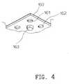
- FIG. 4is a cut perspective view of the film onto which the plurality of individual step keys are fixed.
- the film 160includes circular holes 161 and 162 into which the extensions of the individual step keys are inserted and a protrusion 163 that presses a metal dome when a step key is pressed down.
- the number of holes 161 and 162is identical to that of the extensions of the individual step keys.
- FIG. 5illustrates sections of the individual step key 150 utilized to describe a procedure of fixing the individual step key 150 on the film 160.
- the extension 156 of the step key 150 that was individually injection-moldedis inserted into a hole of the film 160.
- the extension 156is formed into a rivet 157 by ultrasonic laser beam processing, to thereby engage the individual step key 150 on to the film 160.
- the plurality of individual step keys 150are fixed on the film 160, forming the step key assembly 150 shown in FIG. 2 .
- FIG. 6is a sectional view of a data input device in the terminal having the first step key assembly 15.
- the data input deviceis comprised of the plurality of step keys 150, the film 160 on which the step keys 150 are fixed, protrusions 163 extended downward from the film 160, known metal domes 171 (including not-shown carbon contact points) that are pressed by the protrusions 163, and a PCB (Printed Circuit Board) 170 connected to the metal domes 171.
- the center of the contactsi.e. metal domes 171
- the protrusions 163return in a direction 2 by the elasticity of the metal domes 171.
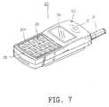
- FIG. 7is a perspective view of a terminal having a second embodiment of a step key assembly 25
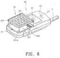
- FIG. 8is a perspective view of the terminal and the step key assembly 25 that are separated from each other
- FIG. 9is a perspective bottom view of the step key assembly 25.
- the terminalis comprised of a main body 20 having a recess 201 at a predetermined position, an antenna device 21 at an upper end of the main body 20, an earpiece 23 under the antenna device 21, a display 24 under the earpiece 23, the independent step key assembly 25 assembled in the recess 201 under the display 24, a double-sided tape 254 for fixing the step key assembly 25 in the recess 201, a connection portion including first and second terminals 202 and 253 for electrically connecting the step key assembly 25 to the main body 20, and a microphone 26 under the step key assembly 25.
- the step key assembly 25is placed down and fixed in the recess 201.
- the double-sided tape 254is attached to the bottom surface 252a of the key assembly 25 to fix the step key assembly 25 on the bottom surface 201 a of the recess 201.
- the first and second terminals 202 and 253are disposed at a first predetermined position on the recess bottom surface 201 and at a second predetermined position on the key assembly bottom surface 252a, respectively.
- the step key assembly 25is attached in the recess 201, the first and second terminals 202 and 253 are connected.
- the step key assembly 25is electrically connected to a PCB (not shown) of the main body 20.
- Reference numeral 22denotes an incoming call lamp.
- step key assembly 25includes a casing frame 252 and step keys 251 which are arranged in rows and columns in contact with each other, it is to be noted that the step key assembly 25 further includes a film (not shown), which has been described above in detail. Though not shown, the film, metal domes, and the PCB or flexible printed circuit are disposed under the step keys 251. The second terminals 253 are connected to the PCB or the flexible printed circuit.
- the location of the first terminals 202is not limited to a corner of the recess bottom surface 201 a.
- the first terminals 202may be located at the center or a sidewall of the recess 202.
- the location of the second terminals 253is not limited to the corner of the bottom surface 252a of the casing frame 252 either.
- the second terminals 253may also be located at the center of the bottom surface 252a or on a side of the casing frame 252.
- a different means for electrically connecting the step key assembly 25 to the main body 20can be used instead of the first and second terminals 202 and 253.
- the first and second terminals 202 and 253can be replaced with a pair of female/male connectors, particularly a pair of female/male connectors using a flat-type cable, in consideration of assembly facility.
- FIG. 10is a perspective view of a terminal to which a third embodiment of a step key assembly 35 is applied.
- the terminalincludes a main body 30, an antenna device 31 at an uppermost end of the main body 30, an earpiece 33 under the antenna device 31, a display 34 under the earpiece 33, for displaying input data, the step key assembly 35 to be pressed when data is entered, and a microphone 36 under the step key assembly 35.
- Only the top side of the step key assembly 35is exposed from the upper surface 301 of the main body 30.
- individual step keys 351contact with each other in a transverse direction and are separated from each other in a longitudinal direction. That is, the step keys 351 are arranged in rows and columns and the rows are spaced from each other by a predetermined distance.
- Main body support frames 302are located in the spaces S between the rows. The support frames 302 are extended in the transverse direction.
- FIG. 11is a perspective view of the step key assembly 35.
- the step key assembly 35includes a plurality of step keys 351 and a film 352 on which the step keys 351 are fixed.
- the step key 351are fixed on the film 352 in such a way that they contact each other in the transverse direction and are spaced by the distance S in the longitudinal direction.
- the step keys 351are arranged in the transverse direction in the order of first to fourth rows.
- the top ends of the step keys 351are exposed from the main body 30.
- the top end of an individual step key 351is divided into a first slope portion and a second slope portion connected to the first slope portion.
- the step keys 351are fixed on the film 352 as in the procedure shown in FIG. 5 , which will not be described again.
- FIG. 12is a perspective view of a terminal to which a fourth embodiment of a step key assembly 45 is applied and FIG. 13 is a perspective view of the terminal and the step key assembly 45 that are separated from each other.
- the terminalis comprised of a main body 40 having a recess 402 at a predetermined position, an antenna device 41 at an upper end of the main body 40, an earpiece 43 under the antenna device 41, a display 44 under the earpiece 43, the independent step key assembly 45 assembled in the recess 402 under the display 44, a double-sided tape (not shown) identical to that shown in FIG.
- a connection portion including first and second terminals(only the first terminals are shown in FIG. 13 and the second terminals are identical to those shown in FIG. 9 ), for electrically connecting the step key assembly 45 to the main body 40, and a microphone 46 under the step key assembly 45.
- the step key assembly 45is placed down and fixed in the recess 402.
- the double-sided tapeis attached to the bottom surface of the step key assembly 45 as shown in FIG. 9 , in order to fix the step key assembly 45 on the bottom surface 402a of the recess 402.
- the first terminals 403are disposed at a predetermined position on therecess bottom surface 402a and the second terminals are disposed at the same position as shown in FIG.
- step key assembly 45When the step key assembly 45 is attached in the recess 402, the first terminals 403 and second terminals are connected. As a result, the step key assembly 45 is electrically connected to a PCB (not shown) of the main body 40.
- Reference numeral 42denotes an incoming call lamp.
- the step key assembly 45includes a casing frame 450 and step keys 451 at the top ends of which are exposed in the casing frame 450, it is to be noted that the step key assembly 45 further includes a film (not shown) identical to that shown in FIG. 4 . Though not shown, the film, metal domes, and the PCB or flexible printed circuit are disposed under the step keys 451. The second terminals are connected to the PCB or the flexible printed circuit.
- the step key assembly 45is so installed that only the top ends of the step keys 451 are exposed from the casing frame 450 and the step keys 451 contact each other in a transverse direction, being spaced from each other in a longitudinal direction.
- the casing frame 450has a plurality of support frames 450a.
- the support frames 450aare extended in the transverse direction, being spaced from each other in a longitudinal direction.
- the location of the first terminals 403is not limited to a corner of the recess bottom surface 402a.
- the first terminals 403may be located at the center or a sidewall of the recess 402.
- the location of the second terminalsis not limited to a corner under the step key assembly 45, either.
- the second terminalsmay also be located at the center or on a side under the step key assembly 45.
- first terminals 403 and second terminalscan be replaced with a pair of female/male connectors, particularly a pair of female/male connectors using a flat-type cable, in consideration of assembly facility.
- FIG. 14is a perspective view of a terminal to which a fifth embodiment of a step key assembly 55 is applied.
- step keys 551are arranged in the same manner as shown in FIG. 2 .
- the step key assembly 55is fixed in a recess 501 of a main body 50 via hooks 552 and holes 501 b.
- the hooks 552are extended downward from predetermined positions of the step key assembly 55 and the holes 501b are formed at predetermined positions of a recess bottom surface 501 a corresponding to the positions of the hooks 552. Insertion of the hooks 552 into the holes 501b maintains the step key assembly 55 fixed in the recess 501.
- First terminals 503are disposed at a predetermined position of the recess 501 and second terminals (not shown) are provided on the bottom surface of the step key assembly 55.
- FIG. 15is a perspective view of a terminal and a sixth embodiment of a step key assembly 65 that is removed from the terminal.
- step keys 651are arranged in the same manner as shown in FIG. 10 .
- the step key assembly 65is fixed in a main body recess 601 via hooks 652 and holes 602.
- the hooks 652are extended downward from predetermined positions of the step key assembly 65 and the holes 602 are formed at predetermined positions of the bottom surface 601a of the recess 601 corresponding to the positions of the hooks 652. Insertion of the hooks 652 into the holes 602 maintains the step key assembly 65 fixed in the recess 601. It is preferable to form the hooks 652 symmetrically.
- a means for electrically connecting the step key assembly 65 to a main body 60has been stated before.
- First terminals 603are disposed in the recess 601 and second terminals (not shown) are provided on the bottom surface of the step key assembly.
- FIG. 16is a plan view of a terminal to which a step key or keypad assembly 75 according to an embodiment of the present invention is applied.
- the terminalhas a main body 70 with an upper casing frame 78 and a lower casing frame (not shown), a sub-body (not shown) installed to be opened/closed according to user choice, and a hinge arm 77 by which the sub-body can be placed to an open/closed position with respect to the main body 70.
- the sub-bodycan be a flip cover or a folder that protects the keypad assembly and is rotatable at a predetermined communication angle.
- An antenna device 71is installed at an uppermost end of the main body 70.
- An earpiece 73 and an LCD module 74are sequentially disposed under the antenna device 71.
- the keypad assembly 75 and a microphone 76are sequentially arranged on the main body 70.
- the comers of the keypad assembly 75are fixed to the inner side surfaces of the frame 78 without forming holes on the frame 78 for protrusion of a plurality of key buttons.
- FIG. 17is a partial sectional view of the terminal shown in FIG. 16 according to the embodiment of the present invention.
- a silicon keypad rubber 770is installed on the upper casing frame 78.
- a plurality of button portions spaced from each other by a predetermined distanceare integrated with contact point protrusions 771 extended downward from the button portions in the keypad rubber 770.
- a film sheet 760 of the same patternis attached onto the upper surface of the keypad rubber 770 in order to protect the keypad rubber 770 against damage.
- Hard key buttons 750are individually attached on the button portions covered with the film sheet 760 so that the distance between the key buttons 750 is very narrow.
- the key buttons 750are formed of plastic.
- the key buttons 750can be attached onto the upper surface of the film sheet 760 by a predetermined adhesive means.
- each key button 750is divided in a first slope portion and a second slope portion larger than the first slope portion in the opposite direction to the first slope portion.
- the key buttons 750are arranged stepwise to facilitate reliable key button pressing.
- a PCB 780 of a predetermined patternis installed on the main body 70.
- the PCB 780has metal domes 781 at positions corresponding to the contact point protrusions 771, so that the contact point protrusions 771 contact the carbon contact points of the PCB 780 via the metal domes 781.
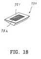
- FIG. 18is a perspective view of the surface of a individual key button 750 to which an adhesive is applied according to the embodiment of the present invention.
- An adhesive tape 751 and an adhesive 752are applied to the lower surface of the key button 750 that contact the film sheet 760.
- the double-sided adhesive tape 751is attached along the periphery of the lower surface of the key button 750.
- An openingis formed at the center of the double-sided adhesive tape 751 and the adhesive 752 is coated on the opening. Therefore, the key button 750 is firmly attached to the film sheet 760. Only one of the double-sided tape 751 and the adhesive 752 can be sued as an adhesive means.
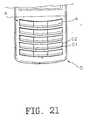
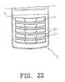
- FIGs. 19 to 22are partial plan views illustrating portions of terminals having step key or keypad assemblies A according to the present invention.
- various modifications of step keys Kcan be exist and arranged in the step key assemblies A in diverse manners according to the present invention.
- first and second slope portions C1 and C2can be designed in various shapes on the top ends of the individual step keys K, exposed from the upper surface of main bodies.
- the first slope portions C1may be lower than the second slope portions C2.
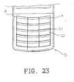
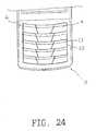
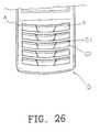
- FIGs. 23 to 26are plan views illustrating portions of other terminals having step key assemblies A according to the present invention.
- various modifications of step keys Kcan be exist and arranged in the step key assemblies A in diverse manners according to the present invention.
- first and second slope portions C1 and C2can be designed in various shapes on the top ends of the individual step keys K, exposed from the upper surface of main bodies.
- the first slope portions C1may be higher than the second slope portions C2.
- FIG. 27is a plan view illustrating a terminal having a step key or keypad assembly A according to the present invention.
- support framesare arranged on the upper side of a main body B.
- the support framesare separated from each other in a transverse direction.
- the step keys Kare so arranged that they contact each other in a longitudinal direction and are separated in a transverse direction in the step key assembly A applied to the main body B.
Landscapes
- Engineering & Computer Science (AREA)
- Signal Processing (AREA)
- Telephone Set Structure (AREA)
- Push-Button Switches (AREA)
- Input From Keyboards Or The Like (AREA)
Description
- The present invention relates generally to a terminal, and in particular, to a keypad with a plurality of keys that are pressed to enter data like characters or digits.
- Portable terminals are classified into a bar-type, a flip-type, and a folder-type according to their outer appearances. The flip-type and folder-type ones are more commonplace because they are feasible for miniaturization of main bodies and protection of keys. In the case of a flip-type terminal, its flip acts as a sound reflecting plate and a microphone can be installed on the flip. In the case of a folder-type terminal, its folder acts as a sound reflecting plate and protects a plurality of keys, and an auxiliary device such as an LCD (Liquid Crystal Display) can be installed on the folder. In the future, in terms of performance and design, the terminals will be developed further toward small size and lightweight design, and customers will carry smaller and lighter terminals as accessories.
- The terminal is necessarily provided with a data input device and a data output device to input and output information. A keypad having a plurality of keys that are pressed for entry of data is most widely used as the data input device. Aside from the keypad, data is input by touching a touch screen or by voice using a speech recognition device.
- It is, however, well known that the keypad (or key assembly) occupies a large area on a main body, impeding miniaturization of the terminal. On the other hand, scaling down of individual keys in the keypad will cause a user inconvenience in pressing them and increase pressing errors. Therefore, miniaturization of terminals is incompatible with convenient user key pressing in the conventional technology.
EP-A-0 593 804 discloses an illuminated button key. A single button key comprises a pad with an operating portion and a projecting portion all formed of a flexible rubber. Corresponding keys have movable contacts and fixed contacts separated by a spacer. There is also a non-light permeable coating layer formed on the remaining operation portion, except a flat upper surface of an inflated portion. There is also some other kind of layer that is described as a light permeable adhesive for adhering the back of a chromatic color light permeable layer to the flat upper surface of the inflated portion of the operating portion of the key.JP 11 144574 A - It an object of the present invention to provide a keypad assembly having step keys that are easy to press and feasible for miniaturization of a main body and that will simultaneously prevent errors induced by pressing the keys, as such pressing of a key will have no influence on adjacent keys.
- The above and other objects, features and advantages of the present invention will become more apparent from the following detailed description when taken in conjunction with the accompanying drawings in which:
FIG. 1 is a perspective view of a terminal having a first step key assembly;FIG. 2 is a perspective view of the first step key assembly;FIG. 3 is a sectional perspective view of an individual step key of the first step key assembly according toFig. 2 ;FIG. 4 is a perspective view illustrating a portion of a film on which step keys are fixed;FIG. 5 illustrates a procedure of fixing an individual step key onto the film;FIG. 6 is a sectional view of a data input device having the first step key assembly according to the previous Figs.FIG. 7 is a perspective view of a terminal having a second step key assembly;FIG. 8 is a perspective view of the terminal and the second step key assembly that are separated from each other;FIG. 9 is a perspective bottom view of the second step keyFIG. 10 is a perspective view of a terminal having a third step key assembly;FIG. 11 is a perspective view of the third step key assembly;FIG. 12 is a perspective view of a terminal having a fourth step key assembly;FIG. 13 is a perspective view of the terminal and the fourth step key assembly that are separated from each other;FIG. 14 is a perspective view of a fifth step key assembly separated from a terminal;FIG. 15 is a perspective view of a sixth step key assembly separated from a terminal;FIG. 16 is a plan view of a terminal having a step key assembly according to an embodiment of the present invention;FIG. 17 is a partial sectional view of the step key assembly shown inFIG. 16 ;FIG. 18 is a perspective view of the surface of a key button to which an adhesive is applied according to the embodiment of the present invention; andFIGs. 19 to 27 are partial plan views of terminals having different arrangements of individual step keys according to the present invention.- Preferred embodiments of the present invention will be described hereinbelow with reference to the accompanying drawings. In the following description, well-known functions or constructions are not described in detail since they would obscure the invention in unnecessary detail.
- It is to be noted that step key assemblies and keypad assemblies are applicable to all terminals including bar-type, flip-type and folder-type ones and including terminals focused on voice transmission and terminals that additionally provide transmission of pictures.
- The following description will be made of step key assemblies applied to bar-type terminals by way of example.
FIG. 1 is a perspective view of a bar-type terminal having a first embodiment of a step key assembly. Referring toFIG. 1 , amain body 10 has an antenna device 11 on an uppermost end, anincoming call lamp 12 on an upper end, anearpiece 13 including a speaker, adisplay 14 for displaying input data, astep key assembly 15 for entering data, and amicrophone 16 at a lowermost end.- Only the top ends of step keys are exposed from the top side of the
main body 10 to allow a user directly to press the step keys. The step keys are assembled into thestep key assembly 15 and fixed to themain body 10. FIG. 2 is a perspective view of the firststep key assembly 15. Referring toFIG. 2 ,individual step keys 150 of thestep key assembly 15 are integrally arranged in rows and columns on afilm 160. Thekeys 150 are stepwise assembled in contact with each other on thefilm 160.- The configuration of an
individual step key 150 will be described with reference toFIG. 3 . Theindividual step key 150 shown inFIG. 3 is in an injection-molded state before it is assembled on the film. The top end of theindividual step key 150 is divided into afirst slope portion 151 inclined at a first predetermined angle and asecond slope portion 152 connected to thefirst slope portion 151 and inclined at a second predetermined angle in the opposite direction to thefirst slope portion 151. Thefirst slope portion 151 is smaller in area than thesecond slope portion 152 and the first predetermined angle is greater than the second predetermined angle. Arecess 153 is formed on the front part of thestep key 150 and aprotrusion 154 is extended from the rear end of thestep key 150. Anextension 156 is extended downward for a predetermined length form thebottom end 155 of theindividual step key 150. Therecess 153 and theprotrusion 154 are used to integrally fix a plurality ofindividual step keys 150 on the film. Theextension 156 is preferably engaged into the film by an ultrasonic laser beam. At least oneextension 156 is preferably formed on thebottom end 155 to more securely fix theindividual step key 150 to the film. The height of W1 of therecess 153 is greater than the height W2 of theprotrusion 154 to provide a movement space for theindividual step key 150 with respect to an adjacent step key when it is pressed down to enter data using the step key assembly. FIG. 4 is a cut perspective view of the film onto which the plurality of individual step keys are fixed. Thefilm 160 includescircular holes protrusion 163 that presses a metal dome when a step key is pressed down. The number ofholes FIG. 5 illustrates sections of theindividual step key 150 utilized to describe a procedure of fixing theindividual step key 150 on thefilm 160. Referring toFIG. 5 , theextension 156 of thestep key 150 that was individually injection-molded is inserted into a hole of thefilm 160. Then, theextension 156 is formed into arivet 157 by ultrasonic laser beam processing, to thereby engage theindividual step key 150 on to thefilm 160. In this manner, the plurality ofindividual step keys 150 are fixed on thefilm 160, forming the stepkey assembly 150 shown inFIG. 2 .FIG. 6 is a sectional view of a data input device in the terminal having the first stepkey assembly 15. Referring toFIG. 6 , the data input device is comprised of the plurality ofstep keys 150, thefilm 160 on which thestep keys 150 are fixed,protrusions 163 extended downward from thefilm 160, known metal domes 171 (including not-shown carbon contact points) that are pressed by theprotrusions 163, and a PCB (Printed Circuit Board) 170 connected to the metal domes 171. When the user presses thestep keys 150 in adirection 1 to enter data, the centers of the contacts, i.e.metal domes 171, contact thePCB 170 by theprotrusions 163. Theprotrusions 163 return in adirection 2 by the elasticity of the metal domes 171.FIG. 7 is a perspective view of a terminal having a second embodiment of a stepkey assembly 25,FIG. 8 is a perspective view of the terminal and the stepkey assembly 25 that are separated from each other, andFIG. 9 is a perspective bottom view of the stepkey assembly 25. Referring toFIGs. 7 ,8 and9 , the terminal is comprised of amain body 20 having arecess 201 at a predetermined position, anantenna device 21 at an upper end of themain body 20, anearpiece 23 under theantenna device 21, adisplay 24 under theearpiece 23, the independent stepkey assembly 25 assembled in therecess 201 under thedisplay 24, a double-sided tape 254 for fixing the stepkey assembly 25 in therecess 201, a connection portion including first andsecond terminals key assembly 25 to themain body 20, and amicrophone 26 under the stepkey assembly 25. The stepkey assembly 25 is placed down and fixed in therecess 201. Here, the double-sided tape 254 is attached to the bottom surface 252a of thekey assembly 25 to fix the stepkey assembly 25 on thebottom surface 201 a of therecess 201. The first andsecond terminals recess bottom surface 201 and at a second predetermined position on the key assembly bottom surface 252a, respectively. When the stepkey assembly 25 is attached in therecess 201, the first andsecond terminals key assembly 25 is electrically connected to a PCB (not shown) of themain body 20.Reference numeral 22 denotes an incoming call lamp.- While it is shown that the step
key assembly 25 includes acasing frame 252 and stepkeys 251 which are arranged in rows and columns in contact with each other, it is to be noted that the stepkey assembly 25 further includes a film (not shown), which has been described above in detail. Though not shown, the film, metal domes, and the PCB or flexible printed circuit are disposed under thestep keys 251. Thesecond terminals 253 are connected to the PCB or the flexible printed circuit. - The location of the
first terminals 202 is not limited to a corner of therecess bottom surface 201 a. For example, thefirst terminals 202 may be located at the center or a sidewall of therecess 202. The location of thesecond terminals 253 is not limited to the corner of the bottom surface 252a of thecasing frame 252 either. Thesecond terminals 253 may also be located at the center of the bottom surface 252a or on a side of thecasing frame 252. - A different means for electrically connecting the step
key assembly 25 to themain body 20 can be used instead of the first andsecond terminals second terminals FIG. 10 is a perspective view of a terminal to which a third embodiment of a stepkey assembly 35 is applied. Referring toFIG. 10 , the terminal includes amain body 30, anantenna device 31 at an uppermost end of themain body 30, an earpiece 33 under theantenna device 31, adisplay 34 under the earpiece 33, for displaying input data, the stepkey assembly 35 to be pressed when data is entered, and amicrophone 36 under the stepkey assembly 35. Only the top side of the stepkey assembly 35 is exposed from theupper surface 301 of themain body 30. Here,individual step keys 351 contact with each other in a transverse direction and are separated from each other in a longitudinal direction. That is, thestep keys 351 are arranged in rows and columns and the rows are spaced from each other by a predetermined distance. Main body support frames 302 are located in the spaces S between the rows. The support frames 302 are extended in the transverse direction.FIG. 11 is a perspective view of the stepkey assembly 35. The stepkey assembly 35 includes a plurality ofstep keys 351 and afilm 352 on which thestep keys 351 are fixed. Thestep key 351 are fixed on thefilm 352 in such a way that they contact each other in the transverse direction and are spaced by the distance S in the longitudinal direction. Thestep keys 351 are arranged in the transverse direction in the order of first to fourth rows. After the stepkey assembly 35 is fixedly mounted to the terminal, only the top ends of thestep keys 351 are exposed from themain body 30. As stated before, the top end of anindividual step key 351 is divided into a first slope portion and a second slope portion connected to the first slope portion. Thestep keys 351 are fixed on thefilm 352 as in the procedure shown inFIG. 5 , which will not be described again.FIG. 12 is a perspective view of a terminal to which a fourth embodiment of a stepkey assembly 45 is applied andFIG. 13 is a perspective view of the terminal and the stepkey assembly 45 that are separated from each other. Referring toFIGs. 12 and13 , the terminal is comprised of a main body 40 having arecess 402 at a predetermined position, anantenna device 41 at an upper end of the main body 40, anearpiece 43 under theantenna device 41, adisplay 44 under theearpiece 43, the independent stepkey assembly 45 assembled in therecess 402 under thedisplay 44, a double-sided tape (not shown) identical to that shown inFIG. 9 , for fixing the stepkey assembly 45 in therecess 402, a connection portion including first and second terminals (only the first terminals are shown inFIG. 13 and the second terminals are identical to those shown inFIG. 9 ), for electrically connecting the stepkey assembly 45 to the main body 40, and amicrophone 46 under the stepkey assembly 45. The stepkey assembly 45 is placed down and fixed in therecess 402. Here, the double-sided tape is attached to the bottom surface of the stepkey assembly 45 as shown inFIG. 9 , in order to fix the stepkey assembly 45 on the bottom surface 402a of therecess 402. Thefirst terminals 403 are disposed at a predetermined position on therecess bottom surface 402a and the second terminals are disposed at the same position as shown inFIG. 9 . When the stepkey assembly 45 is attached in therecess 402, thefirst terminals 403 and second terminals are connected. As a result, the stepkey assembly 45 is electrically connected to a PCB (not shown) of the main body 40.Reference numeral 42 denotes an incoming call lamp.- While it is shown that the step
key assembly 45 includes acasing frame 450 and stepkeys 451 at the top ends of which are exposed in thecasing frame 450, it is to be noted that the stepkey assembly 45 further includes a film (not shown) identical to that shown inFIG. 4 . Though not shown, the film, metal domes, and the PCB or flexible printed circuit are disposed under thestep keys 451. The second terminals are connected to the PCB or the flexible printed circuit. - The step
key assembly 45 is so installed that only the top ends of thestep keys 451 are exposed from thecasing frame 450 and thestep keys 451 contact each other in a transverse direction, being spaced from each other in a longitudinal direction. Thecasing frame 450 has a plurality ofsupport frames 450a. The support frames 450a are extended in the transverse direction, being spaced from each other in a longitudinal direction. - The location of the
first terminals 403 is not limited to a corner of the recess bottom surface 402a. For example, thefirst terminals 403 may be located at the center or a sidewall of therecess 402. The location of the second terminals is not limited to a corner under the stepkey assembly 45, either. The second terminals may also be located at the center or on a side under the stepkey assembly 45. - Additionally, a different means for electrically connecting the step
key assembly 45 to the main body 40 can be used instead of thefirst terminals 403 and second terminals. For example, thefirst terminals 403 and second terminals can be replaced with a pair of female/male connectors, particularly a pair of female/male connectors using a flat-type cable, in consideration of assembly facility. FIG. 14 is a perspective view of a terminal to which a fifth embodiment of a stepkey assembly 55 is applied. Referring toFIG. 14 ,step keys 551 are arranged in the same manner as shown inFIG. 2 . The stepkey assembly 55 is fixed in arecess 501 of amain body 50 viahooks 552 andholes 501 b. Thehooks 552 are extended downward from predetermined positions of the stepkey assembly 55 and theholes 501b are formed at predetermined positions of arecess bottom surface 501 a corresponding to the positions of thehooks 552. Insertion of thehooks 552 into theholes 501b maintains the stepkey assembly 55 fixed in therecess 501. Here, it is preferable to form thehooks 552 symmetrically. A means for electrically connecting the stepkey assembly 55 to themain body 50 has been described before in detail.First terminals 503 are disposed at a predetermined position of therecess 501 and second terminals (not shown) are provided on the bottom surface of the stepkey assembly 55.FIG. 15 is a perspective view of a terminal and a sixth embodiment of a stepkey assembly 65 that is removed from the terminal. Referring toFIG. 15 ,step keys 651 are arranged in the same manner as shown inFIG. 10 . The stepkey assembly 65 is fixed in amain body recess 601 viahooks 652 and holes 602. Thehooks 652 are extended downward from predetermined positions of the stepkey assembly 65 and theholes 602 are formed at predetermined positions of thebottom surface 601a of therecess 601 corresponding to the positions of thehooks 652. Insertion of thehooks 652 into theholes 602 maintains the stepkey assembly 65 fixed in therecess 601. It is preferable to form thehooks 652 symmetrically. A means for electrically connecting the stepkey assembly 65 to a main body 60 has been stated before.First terminals 603 are disposed in therecess 601 and second terminals (not shown) are provided on the bottom surface of the step key assembly.FIG. 16 is a plan view of a terminal to which a step key orkeypad assembly 75 according to an embodiment of the present invention is applied. Referring toFIG. 16 , the terminal has amain body 70 with anupper casing frame 78 and a lower casing frame (not shown), a sub-body (not shown) installed to be opened/closed according to user choice, and ahinge arm 77 by which the sub-body can be placed to an open/closed position with respect to themain body 70. Though not shown, the sub-body can be a flip cover or a folder that protects the keypad assembly and is rotatable at a predetermined communication angle.- An
antenna device 71 is installed at an uppermost end of themain body 70. Anearpiece 73 and anLCD module 74 are sequentially disposed under theantenna device 71. Thekeypad assembly 75 and amicrophone 76 are sequentially arranged on themain body 70. - Since the
keypad assembly 75 is integrally formed, the comers of thekeypad assembly 75 are fixed to the inner side surfaces of theframe 78 without forming holes on theframe 78 for protrusion of a plurality of key buttons. FIG. 17 is a partial sectional view of the terminal shown inFIG. 16 according to the embodiment of the present invention. Referring toFIG. 17 , asilicon keypad rubber 770 is installed on theupper casing frame 78. A plurality of button portions spaced from each other by a predetermined distance are integrated withcontact point protrusions 771 extended downward from the button portions in thekeypad rubber 770. Afilm sheet 760 of the same pattern is attached onto the upper surface of thekeypad rubber 770 in order to protect thekeypad rubber 770 against damage.- Hard
key buttons 750 are individually attached on the button portions covered with thefilm sheet 760 so that the distance between thekey buttons 750 is very narrow. Thekey buttons 750 are formed of plastic. Thekey buttons 750 can be attached onto the upper surface of thefilm sheet 760 by a predetermined adhesive means. - The upper surface of each
key button 750 is divided in a first slope portion and a second slope portion larger than the first slope portion in the opposite direction to the first slope portion. Thus, thekey buttons 750 are arranged stepwise to facilitate reliable key button pressing. - A
PCB 780 of a predetermined pattern is installed on themain body 70. ThePCB 780 hasmetal domes 781 at positions corresponding to thecontact point protrusions 771, so that thecontact point protrusions 771 contact the carbon contact points of thePCB 780 via the metal domes 781. FIG. 18 is a perspective view of the surface of a individualkey button 750 to which an adhesive is applied according to the embodiment of the present invention. Anadhesive tape 751 and an adhesive 752 are applied to the lower surface of thekey button 750 that contact thefilm sheet 760. As shown inFIG. 18 , the double-sidedadhesive tape 751 is attached along the periphery of the lower surface of thekey button 750. An opening is formed at the center of the double-sidedadhesive tape 751 and the adhesive 752 is coated on the opening. Therefore, thekey button 750 is firmly attached to thefilm sheet 760. Only one of the double-sided tape 751 and the adhesive 752 can be sued as an adhesive means.FIGs. 19 to 22 are partial plan views illustrating portions of terminals having step key or keypad assemblies A according to the present invention. As shown inFIGs. 19 to 22 , various modifications of step keys K can be exist and arranged in the step key assemblies A in diverse manners according to the present invention. Particularly, first and second slope portions C1 and C2 can be designed in various shapes on the top ends of the individual step keys K, exposed from the upper surface of main bodies. Furthermore, the first slope portions C1 may be lower than the second slope portions C2.FIGs. 23 to 26 are plan views illustrating portions of other terminals having step key assemblies A according to the present invention. As shown inFIGs. 23 to 26 , various modifications of step keys K can be exist and arranged in the step key assemblies A in diverse manners according to the present invention. Particularly, first and second slope portions C1 and C2 can be designed in various shapes on the top ends of the individual step keys K, exposed from the upper surface of main bodies. Furthermore, the first slope portions C1 may be higher than the second slope portions C2.FIG. 27 is a plan view illustrating a terminal having a step key or keypad assembly A according to the present invention. Referring toFIG. 27 , support frames are arranged on the upper side of a main body B. The support frames are separated from each other in a transverse direction. The step keys K are so arranged that they contact each other in a longitudinal direction and are separated in a transverse direction in the step key assembly A applied to the main body B.- In accordance with the present invention as described above, use of individual keys and a step key or keypad assembly with the step keys fixed on a film as a data input device offers the benefits of easy key pressing to users, and the benefits of miniaturization of a main body of a terminal, maximization of key size, and assembly facility to manufacturers. In addition, since key buttons are individually attached on the upper surface of a film sheet in a keypad assembly of a portable radio terminal according to the present invention, pressing of a particular key has no influence on its adjacent keys. That is, errors can be prevented in pressing keys. A user can enter data conveniently because the present invention enables a small main body and large keys to be achieved. Furthermore, terminals according to the present invention can be readily assembled.
- While the invention has been shown and described with reference to certain preferred embodiments thereof, it will be understood by those skilled in the art that various changes in form and details may be made therein without departing from the scope of the invention as defined by the appended claims.
Claims (4)
- A key pad assembly in a portable radio terminal comprising:a rubber keypad (770) having a plurality of contact point protrusions (771);a button portion (75) integrally formed on each contact point protrusion; anda plurality of hard key buttons (750) individually fixed on the button portions,characterized in thatsaid contact point protrusions (771) are adapted to press down a plurality of metal domes (781) on a printable circuit board, PCB (780), of a main body (70) of the portable radio terminal, and a thin film sheet (760) is attached on the upper surface of the rubber keypad (770), wherein each key button (750) is shaped into a step having a first slope portion and a second slope portion larger in area than the first slope portion and inclined in an opposite direction.
- The keypad assembly according to claim 1,characterized in that the key buttons (750) are fixed on the film sheet (760) by an adhesive means.
- The keypad assembly according to claim 2,characterized in that the adhesive means includes a double-sided adhesive tape (751) having an opening at the center thereof and being attached along the periphery of the lower surface of a key button (750), and an adhesive (752) to be coated on the opening of the adhesive tape (751).
- The keypad assembly according to one of the previous claims,characterized in that each button (750) is formed of plastic.
Applications Claiming Priority (5)
| Application Number | Priority Date | Filing Date | Title |
|---|---|---|---|
| KR2000025975 | 2000-05-16 | ||
| KR1020000025975AKR100640494B1 (en) | 2000-05-16 | 2000-05-16 | Terminal with single staircase key, staircase key assembly and staircase key assembly |
| KR1020000055680AKR100338641B1 (en) | 2000-09-22 | 2000-09-22 | Key pad assembly for portable radiotelephone |
| KR2000055680 | 2000-09-22 | ||
| EP01111873AEP1156643B1 (en) | 2000-05-16 | 2001-05-16 | Step keys, step key assembly, and terminal having the step key assembly |
Related Parent Applications (1)
| Application Number | Title | Priority Date | Filing Date |
|---|---|---|---|
| EP01111873ADivisionEP1156643B1 (en) | 2000-05-16 | 2001-05-16 | Step keys, step key assembly, and terminal having the step key assembly |
Publications (2)
| Publication Number | Publication Date |
|---|---|
| EP1507273A1 EP1507273A1 (en) | 2005-02-16 |
| EP1507273B1true EP1507273B1 (en) | 2012-08-15 |
Family
ID=36371766
Family Applications (2)
| Application Number | Title | Priority Date | Filing Date |
|---|---|---|---|
| EP01111873AExpired - LifetimeEP1156643B1 (en) | 2000-05-16 | 2001-05-16 | Step keys, step key assembly, and terminal having the step key assembly |
| EP04027445AExpired - LifetimeEP1507273B1 (en) | 2000-05-16 | 2001-05-16 | Keypad assembly |
Family Applications Before (1)
| Application Number | Title | Priority Date | Filing Date |
|---|---|---|---|
| EP01111873AExpired - LifetimeEP1156643B1 (en) | 2000-05-16 | 2001-05-16 | Step keys, step key assembly, and terminal having the step key assembly |
Country Status (3)
| Country | Link |
|---|---|
| US (2) | US6495784B2 (en) |
| EP (2) | EP1156643B1 (en) |
| DE (1) | DE60114706T2 (en) |
Families Citing this family (52)
| Publication number | Priority date | Publication date | Assignee | Title |
|---|---|---|---|---|
| US7027844B2 (en) | 2000-12-29 | 2006-04-11 | Vertu Limited | Mobile telephone |
| GB2371020B (en)* | 2000-12-29 | 2005-07-27 | Nokia Mobile Phones Ltd | A mobile telephone |
| US6965789B2 (en) | 2000-12-29 | 2005-11-15 | Vertu Limited | Portable communication device |
| GB2371021B (en)* | 2000-12-29 | 2005-07-27 | Nokia Mobile Phones Ltd | A portable communication device |
| GB2371019B (en)* | 2000-12-29 | 2005-07-27 | Nokia Mobile Phones Ltd | Mobile telephone |
| US7444173B2 (en) | 2000-12-29 | 2008-10-28 | Vertu Ltd. | Mobile telephone |
| US7203309B2 (en) | 2000-12-29 | 2007-04-10 | Vertu Limited | Mobile telephone |
| GB2371022B (en)* | 2000-12-29 | 2005-01-12 | Nokia Mobile Phones Ltd | A portable communication device |
| AUPS138102A0 (en)* | 2002-03-28 | 2002-05-09 | Platysys Pty Ltd | Reconfigurable switch |
| US6822853B2 (en)* | 2002-04-18 | 2004-11-23 | Symbol Technologies, Inc. | Method and system for assembling keypad |
| EP1355478A1 (en)* | 2002-04-19 | 2003-10-22 | Chih-Ming Chang | Upper casing part for electronic apparatus |
| TW549555U (en)* | 2002-10-25 | 2003-08-21 | High Tech Comp Corp | Button apparatus with a speaker |
| DE10258209A1 (en) | 2002-12-12 | 2004-06-24 | Siemens Ag | Module with input device for mobile telephone incorporates flexible carrier with cap mounted in frame and includes mechanically- stable fixing member |
| US7195169B2 (en)* | 2003-07-23 | 2007-03-27 | Symbol Technologies, Inc. | Mobile terminal with ergonomic housing |
| FR2865601B1 (en)* | 2004-01-28 | 2006-04-07 | Sagem | TELEPHONE COMPRISING A KEYBOARD WITH JOINTIVE TOUCHES |
| JP4155405B2 (en)* | 2004-03-24 | 2008-09-24 | ソニー・エリクソン・モバイルコミュニケーションズ株式会社 | Portable electronic device and mobile phone device |
| US20060062626A1 (en)* | 2004-09-22 | 2006-03-23 | Symbol Technologies, Inc. | Keypad ergonomics |
| JP2006244823A (en)* | 2005-03-02 | 2006-09-14 | Fuji Photo Film Co Ltd | Operating member |
| US7525534B2 (en) | 2005-03-14 | 2009-04-28 | Palm, Inc. | Small form-factor keypad for mobile computing devices |
| US9142369B2 (en) | 2005-03-14 | 2015-09-22 | Qualcomm Incorporated | Stack assembly for implementing keypads on mobile computing devices |
| EP2293167A3 (en)* | 2005-03-14 | 2012-01-18 | Hewlett-Packard Development Company, L.P. | Small form-factor keypad for mobile computing devices |
| EP2144262B1 (en)* | 2005-06-03 | 2010-12-08 | Research In Motion Limited | Handheld electronic device and keypad having tactile features |
| US7433719B2 (en) | 2005-06-03 | 2008-10-07 | Research In Motion Limited | Handheld electronic device and keypad having tactile features |
| JP4394047B2 (en)* | 2005-08-05 | 2010-01-06 | 信越ポリマー株式会社 | Cover member for key frame and push button switch |
| US7832628B2 (en)* | 2005-10-21 | 2010-11-16 | Verifone, Inc. | Protective cover for terminal keypad security switches |
| CA2640204C (en) | 2006-01-27 | 2016-11-01 | University Of South Florida | Accelerated aging process for acoustic stringed instruments |
| US8662245B1 (en) | 2006-01-27 | 2014-03-04 | University Of South Florida | Frequency response treatment of wood paneling |
| US7977555B2 (en)* | 2006-01-27 | 2011-07-12 | University Of South Florida | Method of modifying the frequency response of a wooden article |
| US20070215451A1 (en)* | 2006-03-16 | 2007-09-20 | Michael Sasloff | Mobile device arrangement including replaceable touch panel |
| US7629547B2 (en)* | 2006-04-24 | 2009-12-08 | Nokia Corporation | Illuminating of an electrical device |
| US7948765B2 (en)* | 2006-08-11 | 2011-05-24 | Bunn-O-Matic Corporation | Reconfigurable control panel |
| ATE455356T1 (en)* | 2006-10-30 | 2010-01-15 | Research In Motion Ltd | KEYBOARD WITH BUTTONS HAVING SLOPED ACTUATING SURFACES |
| US8254564B2 (en) | 2006-10-30 | 2012-08-28 | Research In Motion Limited | Keypad having keys with angled engagement surfaces, and associated handheld electronic device |
| KR100834633B1 (en)* | 2006-11-06 | 2008-06-02 | 삼성전자주식회사 | Keypad combination structure of mobile terminal |
| JP4931561B2 (en)* | 2006-11-16 | 2012-05-16 | シャープ株式会社 | Information processing terminal |
| TWM324815U (en)* | 2007-05-08 | 2008-01-01 | Universal Scient Ind Co Ltd | Keycap unit and keyboard structure applying the same |
| USD593052S1 (en)* | 2007-10-02 | 2009-05-26 | Htc Corporation | Mobile communication device |
| US8274410B2 (en)* | 2007-10-22 | 2012-09-25 | Sony Ericsson Mobile Communications Ab | Data input interface and method for inputting data |
| JP2009105634A (en)* | 2007-10-23 | 2009-05-14 | Docomo Technology Inc | Communication terminal device |
| US8400400B2 (en) | 2007-11-05 | 2013-03-19 | Research In Motion Limited | Raised rail enhanced reduced keyboard upon a handheld electronic device |
| EP2056184A1 (en)* | 2007-11-05 | 2009-05-06 | Research In Motion Limited | Tactile rails for dividing a keyboard |
| TWM335731U (en)* | 2008-01-09 | 2008-07-01 | Ichia Tech Inc | Lateral lighting keypress module and using keypress panel thereof |
| TW200931468A (en)* | 2008-01-09 | 2009-07-16 | Ichia Tech Inc | Manufacturing method of key cap to emit light in the lateral direction |
| USD602012S1 (en)* | 2008-12-15 | 2009-10-13 | Samsung Electronics Co., Ltd. | Keypad for portable phone |
| USD612372S1 (en)* | 2008-12-23 | 2010-03-23 | Research In Motion Limited | Keypad |
| USD611464S1 (en)* | 2009-03-20 | 2010-03-09 | Nokia Corporation | Keypad for a handset |
| CN101925276B (en)* | 2009-06-09 | 2012-11-21 | 深圳富泰宏精密工业有限公司 | Portable electronic device |
| JPWO2011004878A1 (en)* | 2009-07-10 | 2012-12-20 | 日本電気株式会社 | Operation keys and terminal device |
| TWM413205U (en)* | 2011-03-08 | 2011-10-01 | Weistech Technology Co Ltd | Portable appliance key module structure |
| EP2405457A1 (en)* | 2010-07-09 | 2012-01-11 | Koninklijke Philips Electronics N.V. | Modular keyboard assembly |
| JP6245103B2 (en)* | 2014-07-28 | 2017-12-13 | 京セラドキュメントソリューションズ株式会社 | Image processing device |
| USD836638S1 (en)* | 2017-01-13 | 2018-12-25 | Symbol Technologies, Llc | Mobile computing device |
Family Cites Families (28)
| Publication number | Priority date | Publication date | Assignee | Title |
|---|---|---|---|---|
| US3800104A (en)* | 1972-11-13 | 1974-03-26 | Becton Dickinson Co | Low profile keyboard switch assembly with snap action cantilever contact |
| US4029916A (en)* | 1975-04-18 | 1977-06-14 | Northern Electric Company Limited | Multi-contact push-button switch and plural embodiment for keyboard switch assembly |
| US4066850A (en)* | 1976-06-04 | 1978-01-03 | Ncr Corporation | Keyboard switch assembly having interchangeable cover plate, indicating layer and actuator switch assembly in any operative combination |
| US4096364A (en)* | 1977-02-22 | 1978-06-20 | Chomerics, Inc. | Keyboard switch assembly having flexible contact layer with snap initiator dome |
| SU676983A1 (en)* | 1978-03-28 | 1979-07-30 | Ордена Ленина Институт Проблем Управления | Keyboard |
| GB1593414A (en)* | 1978-05-19 | 1981-07-15 | Jermyn Holdings Ltd | Keyboard switch assemblies |
| US4352968A (en)* | 1981-02-09 | 1982-10-05 | Kb Denver, Inc. | Elastomeric boot for a keyboard subassembly |
| JPS5866216A (en)* | 1981-10-16 | 1983-04-20 | 信越ポリマ−株式会社 | Keyboard unit |
| JPS58117619A (en)* | 1981-12-29 | 1983-07-13 | キヤノン株式会社 | Electronic equipment |
| US4430531A (en)* | 1982-03-15 | 1984-02-07 | Hewlett-Packard Company | Snap disc keyboard |
| GB2165696A (en)* | 1984-10-11 | 1986-04-16 | Immediate Business Systems Plc | Keyboards |
| US4987277A (en)* | 1990-01-31 | 1991-01-22 | Tapeswitch Corporation Of America | Normally closed pressure-actuated switch |
| JP2627692B2 (en) | 1991-09-20 | 1997-07-09 | サンアロー 株式会社 | Illuminated key |
| US5360955A (en)* | 1992-08-18 | 1994-11-01 | Key Tronic Corporation | Computer keyboard with cantilever switch design and improved PCB/switch membrane interface |
| US5387042A (en)* | 1993-06-04 | 1995-02-07 | Brown; Carl W. | Multilingual keyboard system |
| DE4405754A1 (en)* | 1994-02-23 | 1995-08-24 | Sel Alcatel Ag | Pushbutton arrangement |
| JPH07336263A (en)* | 1994-06-03 | 1995-12-22 | Kokusai Electric Co Ltd | Splashproof structure of the key button |
| DE19505852C1 (en)* | 1995-02-21 | 1996-05-15 | Preh Elektro Feinmechanik | Keyboard panel with protective foil e.g. for cash registers |
| DE19506509C2 (en)* | 1995-02-24 | 1996-12-05 | Preh Elektro Feinmechanik | Keypad for sales and cash registers |
| JP3326765B2 (en)* | 1995-07-07 | 2002-09-24 | ホシデン株式会社 | keyboard |
| JP3151553B2 (en)* | 1996-11-29 | 2001-04-03 | 帝国通信工業株式会社 | Key top plate and manufacturing method thereof |
| JPH11144574A (en) | 1997-11-07 | 1999-05-28 | Toshiba Corp | Operating device for switchgear |
| JPH11144547A (en)* | 1997-11-11 | 1999-05-28 | Porimatec Kk | Combination key pad and its manufacture |
| TW446616B (en)* | 1999-01-27 | 2001-07-21 | Taisei Plastics Co Ltd | Control panel having sheet-formed pushbutton unit and method of producing the same |
| CN1197105C (en)* | 1999-08-27 | 2005-04-13 | 三菱电机株式会社 | Push button switches and switchgear |
| JP2001084863A (en)* | 1999-09-13 | 2001-03-30 | Polymatech Co Ltd | Sheet-shaped key top |
| US6140596A (en)* | 2000-01-04 | 2000-10-31 | Shin Jiuh Corporation | Tact switch |
| JP4514884B2 (en)* | 2000-03-28 | 2010-07-28 | ポリマテック株式会社 | Film integrated key top |
- 2001
- 2001-05-15USUS09/855,880patent/US6495784B2/ennot_activeExpired - Lifetime
- 2001-05-16EPEP01111873Apatent/EP1156643B1/ennot_activeExpired - Lifetime
- 2001-05-16EPEP04027445Apatent/EP1507273B1/ennot_activeExpired - Lifetime
- 2001-05-16DEDE60114706Tpatent/DE60114706T2/ennot_activeExpired - Lifetime
- 2002
- 2002-07-31USUS10/209,100patent/US6664486B2/ennot_activeExpired - Lifetime
Also Published As
| Publication number | Publication date |
|---|---|
| EP1507273A1 (en) | 2005-02-16 |
| EP1156643B1 (en) | 2005-11-09 |
| EP1156643A2 (en) | 2001-11-21 |
| US6495784B2 (en) | 2002-12-17 |
| DE60114706T2 (en) | 2006-06-01 |
| US6664486B2 (en) | 2003-12-16 |
| EP1156643A3 (en) | 2004-04-14 |
| US20010042681A1 (en) | 2001-11-22 |
| US20020185360A1 (en) | 2002-12-12 |
| DE60114706D1 (en) | 2005-12-15 |
Similar Documents
| Publication | Publication Date | Title |
|---|---|---|
| EP1507273B1 (en) | Keypad assembly | |
| US7620175B2 (en) | Handset device with audio porting | |
| US7547857B2 (en) | Keypad assembly for portable terminal | |
| US7991147B2 (en) | Handset device with laminated architecture | |
| US7834853B2 (en) | Handset keypad | |
| US6968054B2 (en) | Wide keypad and wide keypad mounting structure for preventing ESD | |
| US9239591B2 (en) | Case for a hand held device | |
| KR101243669B1 (en) | Mobile terminal | |
| US6809660B2 (en) | Keypad and electronic device | |
| US20080037769A1 (en) | User interface substrate for handset device | |
| WO2008017191A1 (en) | Sub-assembly for handset device | |
| EP1028445B1 (en) | Support structure for a keypad | |
| KR20080040915A (en) | Keypad combination structure of mobile terminal | |
| US6777632B1 (en) | Multifunctional switch structure | |
| CA2519814C (en) | Keypad assembly for mobile station | |
| US7228111B2 (en) | Keypad structure | |
| KR200415225Y1 (en) | Keypad assembly and personal handheld terminal with same | |
| KR100228301B1 (en) | Structure of button in portable terminal | |
| JP2001357750A (en) | Laminated key sheet | |
| JP2001117703A (en) | Key structure | |
| JP2009260461A (en) | Electronic device | |
| JP2008211520A (en) | Portable electronic devices | |
| JP2000243181A (en) | Pressed-type switch structure | |
| JP2008211521A (en) | Portable electronic devices | |
| JP2001333165A (en) | Mobile phone |
Legal Events
| Date | Code | Title | Description |
|---|---|---|---|
| PUAI | Public reference made under article 153(3) epc to a published international application that has entered the european phase | Free format text:ORIGINAL CODE: 0009012 | |
| AC | Divisional application: reference to earlier application | Ref document number:1156643 Country of ref document:EP Kind code of ref document:P | |
| AK | Designated contracting states | Kind code of ref document:A1 Designated state(s):AT BE CH CY DE DK ES FI FR GB GR IE IT LI LU MC NL PT SE TR | |
| AX | Request for extension of the european patent | Extension state:AL LT LV MK | |
| 17P | Request for examination filed | Effective date:20050602 | |
| AKX | Designation fees paid | Designated state(s):DE FR GB IT | |
| 17Q | First examination report despatched | Effective date:20080611 | |
| GRAP | Despatch of communication of intention to grant a patent | Free format text:ORIGINAL CODE: EPIDOSNIGR1 | |
| GRAS | Grant fee paid | Free format text:ORIGINAL CODE: EPIDOSNIGR3 | |
| GRAA | (expected) grant | Free format text:ORIGINAL CODE: 0009210 | |
| AC | Divisional application: reference to earlier application | Ref document number:1156643 Country of ref document:EP Kind code of ref document:P | |
| AK | Designated contracting states | Kind code of ref document:B1 Designated state(s):DE FR GB IT | |
| REG | Reference to a national code | Ref country code:GB Ref legal event code:FG4D | |
| RAP2 | Party data changed (patent owner data changed or rights of a patent transferred) | Owner name:SAMSUNG ELECTRONICS CO., LTD. | |
| REG | Reference to a national code | Ref country code:DE Ref legal event code:R096 Ref document number:60147000 Country of ref document:DE Effective date:20121011 | |
| PLBE | No opposition filed within time limit | Free format text:ORIGINAL CODE: 0009261 | |
| STAA | Information on the status of an ep patent application or granted ep patent | Free format text:STATUS: NO OPPOSITION FILED WITHIN TIME LIMIT | |
| 26N | No opposition filed | Effective date:20130516 | |
| REG | Reference to a national code | Ref country code:DE Ref legal event code:R097 Ref document number:60147000 Country of ref document:DE Effective date:20130516 | |
| REG | Reference to a national code | Ref country code:FR Ref legal event code:PLFP Year of fee payment:15 | |
| PGFP | Annual fee paid to national office [announced via postgrant information from national office to epo] | Ref country code:DE Payment date:20150422 Year of fee payment:15 Ref country code:GB Payment date:20150422 Year of fee payment:15 | |
| PGFP | Annual fee paid to national office [announced via postgrant information from national office to epo] | Ref country code:IT Payment date:20150421 Year of fee payment:15 Ref country code:FR Payment date:20150422 Year of fee payment:15 | |
| REG | Reference to a national code | Ref country code:DE Ref legal event code:R119 Ref document number:60147000 Country of ref document:DE | |
| GBPC | Gb: european patent ceased through non-payment of renewal fee | Effective date:20160516 | |
| PG25 | Lapsed in a contracting state [announced via postgrant information from national office to epo] | Ref country code:IT Free format text:LAPSE BECAUSE OF NON-PAYMENT OF DUE FEES Effective date:20160516 | |
| REG | Reference to a national code | Ref country code:FR Ref legal event code:ST Effective date:20170131 | |
| PG25 | Lapsed in a contracting state [announced via postgrant information from national office to epo] | Ref country code:FR Free format text:LAPSE BECAUSE OF NON-PAYMENT OF DUE FEES Effective date:20160531 Ref country code:DE Free format text:LAPSE BECAUSE OF NON-PAYMENT OF DUE FEES Effective date:20161201 | |
| PG25 | Lapsed in a contracting state [announced via postgrant information from national office to epo] | Ref country code:GB Free format text:LAPSE BECAUSE OF NON-PAYMENT OF DUE FEES Effective date:20160516 |