EP1507196A2 - Mobile device with on-screen optical navigation - Google Patents
Mobile device with on-screen optical navigationDownload PDFInfo
- Publication number
- EP1507196A2 EP1507196A2EP04254719AEP04254719AEP1507196A2EP 1507196 A2EP1507196 A2EP 1507196A2EP 04254719 AEP04254719 AEP 04254719AEP 04254719 AEP04254719 AEP 04254719AEP 1507196 A2EP1507196 A2EP 1507196A2
- Authority
- EP
- European Patent Office
- Prior art keywords
- camera
- main body
- processor
- mode
- display screen
- Prior art date
- Legal status (The legal status is an assumption and is not a legal conclusion. Google has not performed a legal analysis and makes no representation as to the accuracy of the status listed.)
- Granted
Links
Images


Classifications
- G—PHYSICS
- G06—COMPUTING OR CALCULATING; COUNTING
- G06F—ELECTRIC DIGITAL DATA PROCESSING
- G06F3/00—Input arrangements for transferring data to be processed into a form capable of being handled by the computer; Output arrangements for transferring data from processing unit to output unit, e.g. interface arrangements
- G06F3/01—Input arrangements or combined input and output arrangements for interaction between user and computer
- G06F3/03—Arrangements for converting the position or the displacement of a member into a coded form
- G06F3/0304—Detection arrangements using opto-electronic means
- G06F3/0317—Detection arrangements using opto-electronic means in co-operation with a patterned surface, e.g. absolute position or relative movement detection for an optical mouse or pen positioned with respect to a coded surface
- G—PHYSICS
- G06—COMPUTING OR CALCULATING; COUNTING
- G06F—ELECTRIC DIGITAL DATA PROCESSING
- G06F1/00—Details not covered by groups G06F3/00 - G06F13/00 and G06F21/00
- G06F1/16—Constructional details or arrangements
- G06F1/1613—Constructional details or arrangements for portable computers
- G06F1/1615—Constructional details or arrangements for portable computers with several enclosures having relative motions, each enclosure supporting at least one I/O or computing function
- G06F1/1616—Constructional details or arrangements for portable computers with several enclosures having relative motions, each enclosure supporting at least one I/O or computing function with folding flat displays, e.g. laptop computers or notebooks having a clamshell configuration, with body parts pivoting to an open position around an axis parallel to the plane they define in closed position
- G—PHYSICS
- G06—COMPUTING OR CALCULATING; COUNTING
- G06F—ELECTRIC DIGITAL DATA PROCESSING
- G06F1/00—Details not covered by groups G06F3/00 - G06F13/00 and G06F21/00
- G06F1/16—Constructional details or arrangements
- G06F1/1613—Constructional details or arrangements for portable computers
- G06F1/1626—Constructional details or arrangements for portable computers with a single-body enclosure integrating a flat display, e.g. Personal Digital Assistants [PDAs]
- G—PHYSICS
- G06—COMPUTING OR CALCULATING; COUNTING
- G06F—ELECTRIC DIGITAL DATA PROCESSING
- G06F1/00—Details not covered by groups G06F3/00 - G06F13/00 and G06F21/00
- G06F1/16—Constructional details or arrangements
- G06F1/1613—Constructional details or arrangements for portable computers
- G06F1/1633—Constructional details or arrangements of portable computers not specific to the type of enclosures covered by groups G06F1/1615 - G06F1/1626
- G06F1/1684—Constructional details or arrangements related to integrated I/O peripherals not covered by groups G06F1/1635 - G06F1/1675
- G06F1/1686—Constructional details or arrangements related to integrated I/O peripherals not covered by groups G06F1/1635 - G06F1/1675 the I/O peripheral being an integrated camera
- G—PHYSICS
- G06—COMPUTING OR CALCULATING; COUNTING
- G06F—ELECTRIC DIGITAL DATA PROCESSING
- G06F1/00—Details not covered by groups G06F3/00 - G06F13/00 and G06F21/00
- G06F1/16—Constructional details or arrangements
- G06F1/1613—Constructional details or arrangements for portable computers
- G06F1/1633—Constructional details or arrangements of portable computers not specific to the type of enclosures covered by groups G06F1/1615 - G06F1/1626
- G06F1/1684—Constructional details or arrangements related to integrated I/O peripherals not covered by groups G06F1/1635 - G06F1/1675
- G06F1/169—Constructional details or arrangements related to integrated I/O peripherals not covered by groups G06F1/1635 - G06F1/1675 the I/O peripheral being an integrated pointing device, e.g. trackball in the palm rest area, mini-joystick integrated between keyboard keys, touch pads or touch stripes
- G—PHYSICS
- G06—COMPUTING OR CALCULATING; COUNTING
- G06F—ELECTRIC DIGITAL DATA PROCESSING
- G06F2200/00—Indexing scheme relating to G06F1/04 - G06F1/32
- G06F2200/16—Indexing scheme relating to G06F1/16 - G06F1/18
- G06F2200/163—Indexing scheme relating to constructional details of the computer
- G06F2200/1637—Sensing arrangement for detection of housing movement or orientation, e.g. for controlling scrolling or cursor movement on the display of an handheld computer
Definitions
- the present inventionrelates to user interfaces for mobile devices.
- Mobile devicessuch as personal digital assistants and messaging enabled communications devices are rapidly growing in popularity. More features are being incorporated into mobile devices. For example, there are now messaging enabled mobile phones that have display screens and built-in-cameras. Such phones allow images taken by the camera to be displayed on screen, stored on the phone and wirelessly transmitted as digital photos.
- the use of an integrated camera as an input interface for a mobile communications devicehas been proposed, whereby image information from the camera is converted to text data which can be used as a phone number, Internet address, or mail text to support calling, Internet connection or mail passing.
- the range of input interfaces for on-screen navigationis typically more limited for such compact devices than for larger devices such as laptop and desktop computers.
- navigation control on handheld devicestypically relies on a directional keypad, a stylus, and/or other input devices such as a thumbwheel.
- an on-board optical sensor on a mobile deviceis used to detect relative movement of the device and a reference surface, and-move an on-screen pointer accordingly.
- the optical sensormay also be used as in various modes as a camera and a scanner.
- a mobile deviceincluding a main body, a processor and associated memory housed within the main body, a display screen housed within the main body and responsive to signals from the processor, an optical sensor fixed to the main body for capturing successive images and providing image signals representative of the captured images to the processor, and a navigation module associated with the processor for determining, based on the image signals, a relative movement between the main body and a reference surface and moving a pointer on the display screen based on the determined relative movement.
- an on-screen navigation methodfor a mobile device having a display screen.
- the methodincludes (a) fixing an optical sensor for movement with the display screen; (b) displaying an on-screen pointer on the display screen; (c) capturing successive images of a reference surface through the optical sensor; (d) comparing successive captured images to determine a relative movement between the optical sensor and the reference surface; and e) moving the on-screen pointer on the display screen based on the determined movement.
- Figure 1is a block diagram showing a mobile device to which the present invention may be applied;
- Figure 2is a front view of the mobile device of Figure 1;
- Figure 3is a side view of the mobile device
- Figure 4is a back view of the mobile device
- Figure 5is a partial section view of the mobile device, taken along lines V-V of Figure 4.
- Figure 6is a block diagram of operating modules associated with operating modes of a camera of the mobile device according to embodiments of the present invention.
- Figure 7is a block diagram showing an optical navigation process according to embodiments of the invention.
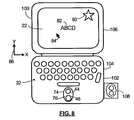
- Figure 8is a front view of a mobile device according to another example embodiment of the invention.
- FIG. 1is a block diagram of a mobile device 10 to which the present invention is applied in an example embodiment.
- the mobile device 10is a handheld two-way mobile communication device having at least data and possibly also voice communication capabilities.
- the device 10has the capability to communicate with other computer systems on the Internet.
- the device 10may be a data communication device, a multiple-mode communication device configured for both data and voice communication, a mobile telephone, a PDA (personal digital assistant) enabled for wireless communication, or a computer system with a wireless modem, among other things.
- the present inventionmay also be applied to handheld computing devices, such as PDAs and digital cameras that are not enabled for communications.
- the device 10includes a communication subsystem 11, including a receiver 12, a transmitter 14, and associated components such as one or more, preferably embedded or internal, antenna elements 16 and 18, and a processing module such as a digital signal processor (DSP) 20.
- the communication subsystem 11includes local oscillator(s) (LO) 13, and in some embodiments the communication subsystem 11 and microprocessor 38 share an oscillator.
- LOlocal oscillator
- the particular design of the communication subsystem 11will be dependent upon the communication network in which the device is intended to operate.
- Signals received by the antenna 16 through a wireless communication network 50are input to the receiver 12, which may perform such common receiver functions as signal amplification, frequency down conversion, filtering, channel selection and the like, and in some embodiments, analog to digital conversion.
- signals to be transmittedare processed, including modulation and encoding for example, by the DSP 20 and input to the transmitter 14 for digital to analog conversion, frequency up conversion, filtering, amplification and transmission over the network 50 via the antenna 18.
- the device 10includes a microprocessor 38 that controls the overall operation of the device 10.
- the microprocessor 38interacts with communications subsystem 11 and also interacts with further device subsystems such as the display 22, flash memory 24, random access memory (RAM) 26, auxiliary input/output (I/O) subsystems 28, serial port 30, keyboard or keypad 32, speaker 34, microphone 36, a short-range communications subsystem 40, and any other device subsystems generally designated as 42.
- the device 10 of the present systemincludes an integral camera 44 and backlight 46 that interact with microprocessor 38.
- Fig. 1Some of the subsystems shown in Fig. 1 perform communication-related functions, whereas other subsystems may provide "resident" or on-device functions. Notably, some subsystems, such as keyboard 32 and display 22 for example, may be used for both communication-related functions, such as entering a text message for transmission over a communication network, and device-resident functions such as a calculator or task list.
- Operating system software 54 and various software applications 58 used by the microprocessor 38are, in one example embodiment, stored in a persistent store such as flash memory 24 or similar storage element. Those skilled in the art will appreciate that the operating system 54, specific device applications 58, or parts thereof, may be temporarily loaded into a volatile store such as RAM 26. It is contemplated that received communication signals may also be stored to RAM 26.
- the microprocessor 38in addition to its operating system functions, preferably enables execution of software applications 58 on the device 10.
- a predetermined set of software applications 58which control basic device operations, including at least data and voice communication applications for example, will normally be installed on the device 10 during manufacture. Further applications may also be loaded onto the device 10 through the network 50, an auxiliary I/O subsystem 28, serial port 30, short-range communications subsystem 40 or any other suitable subsystem 42, and installed by a user in the RAM 26 or a non-volatile store for execution by the microprocessor 38.
- Such flexibility in application installationincreases the functionality of the device 10 and may provide enhanced on-device functions, communication-related functions, or both.
- secure communication applicationsmay enable electronic commerce functions and other such financial transactions to be performed using the device 10.
- a received signalsuch as a text message or web page download will be processed by the communication subsystem 11 and input to the microprocessor 38, which will preferably further process the received signal for output to the display 22, or alternatively to an auxiliary I/O device 28.
- a user of device 10may also compose data items such as email messages for example, using the keyboard 32 in conjunction with the display 22 and possibly an auxiliary I/O device 28. Such composed items may then be transmitted over a communication network through the communication subsystem 11.
- the serial port 30 in Fig. 1would normally be implemented in a personal digital assistant (PDA)-type communication device for which synchronization with a user's desktop computer (not shown) may be desirable, but is an optional device component.
- PDApersonal digital assistant
- Such a port 30would enable a user to set preferences through an external device or software application and would extend the capabilities of the device 10 by providing for information or software downloads to the device 10 other than through the network 50.
- a short-range communications subsystem 40is a further component that may provide for communication between the device 10 and different systems or devices, which need not necessarily be similar devices.
- the subsystem 40may include an infrared device and associated circuits and components or a BluetoothTM communication module to provide for communication with similarly enabled systems and devices.
- the device 10may be a handheld device.
- Wireless mobile network 50is, in an example embodiment, a wireless packet data network, (e.g. MobitexTM or DataTACTM), which provides radio coverage to mobile devices 10, although it could be any other types of wireless networks.
- a wireless packet data networke.g. MobitexTM or DataTACTM
- the components and subsystems of mobile device 10are housed within a hard plastic main body case 70 that is configured to be held with one or two hands while the device 10 is in use.
- the case 70may include a hook (not shown) so that it can be secured to a user's belt or pant's top, or it may be used in conjunction with a soft case (not shown) that can be mounted to the user's belt or pant's top and into which the mobile device 10 can be inserted for carrying.
- Mobile device 10will typically be small enough to fit inside a standard purse or suit jacket pocket.
- the screen 22is visible from the front of the device 10, as is keypad or keyboard 32.
- the keyboard 32includes buttons or keys 90, 92 positioned to be actuated by the thumbs or fingers of the user. In the illustrated embodiment of Figure 2, the keyboard 32 has relatively few keys, however in some embodiments, the keyboard 32 includes 26 or more alphanumeric and control keys.
- the case 70includes a substantially planar back wall 72, which has an opening 74 provided therethrough. A lens 76 covers the opening 74, behind which camera 44 and backlight 46 are located.
- the camera 44 and backlight 46are secured to the back of a printed circuit board 94 that is mounted within the main body case 70.
- the printed circuit board 94also supports at least some of the other hardware electronic components of the device 10.
- the camera 44includes an optical sensor 78 that faces lens 76 for receiving reflected light 100 therethrough.
- the backlight 46is positioned to shine light 98 through the lens 76 onto a reference surface 96 from which it is reflected back to optical sensor 78.
- the camera 44, lens 76 and backlight 46may be adapted to the main body 70 by a variety of other means without narrowing the scope of the invention.
- the camerais fixed to the main body.
- the camera 44, lens 76 and backlight 46may be housed in a secondary housing (not shown) that is pivotally mounted to the body 70 of the device 10.
- the secondary housingmay be removably attached to the body 70 of the device 10.
- camera 44functions, in various modes, as a user input device for controlling the movement of on-screen pointer 84, as a camera for capturing still photo or video images, and as a scanner, among other things.
- the device 10includes as one of the specialized software applications an optical interface engine 60 for processing signals received by the microprocessor 38 from the camera 44 in the manner described below. All or parts of the optical interface engine 60 could, in various embodiments, be integrated into the operating system 54 and/or other specialized applications 58. In some embodiments some of the optical interface engine functions could be implemented in appropriately configured hardware that may be located within the main body 70 or in the same housing as the camera 44.
- Figure 6represents various modules of the optical interface engine 60 according to example embodiments of the invention, which are associated with operating modes of the camera 44 when it is active. More particularly, navigation module 112, digital camera module 114, and scanner module 116 are associated with an optical navigation mode, a digital camera mode, and a scanner mode, respectively. In various embodiments, the camera 44 can be configured to have fewer or greater than three operating modes. In optical navigation mode, the received images from the camera 44 are used to control on screen navigation, as will be explained in greater detail below.
- the camera 44acts as a conventional digital camera, capturing colour still photo images or digital video images, which, among other things, can be stored as image files in a memory of the device 10, viewed on the screen 22, and sent as image files over the network 50 to a destination address.
- scanner modethe camera 44 is used to recognize images representing alphanumeric data and convert the captured images into digital alphanumeric data.
- scanner modehas two sub-modes, namely a barcode scanning mode and an optical character recognition mode.
- barcode scanning modethe camera 44 is used to read barcode information that is then converted by device 10 to a numeric or alphanumeric value that can, among other things, be stored in memory of the device 10, displayed on display 22, and/or transmitted over the network 50 to a destination address.
- optical character recognition moderecognized alphanumeric characters in scanned images are, among other things, stored in memory of the device 10, displayed on display 22, and/or transmitted over the network 50 to a destination address.
- Optical character recognition modecan be used to scan contact information from business cards to an electronic address book, for example.
- a select mode module 110implements a select mode process for selecting among the camera operating modes.
- the useris presented with an on-screen list of the various modes, from which the user can select a desired choice using keyboard 32.
- the select mode processis configured to automatically choose between at least two camera modes based on the images that the camera is currently capturing. For example, when the captured images indicates that the camera 44 is within a threshold distance of a surface 96, navigation mode is selected, but when the camera 44 is further than the threshold distance from a surface 96, the device 10 automatically switches into a digital camera mode.
- the optical sensor 78is a charge coupled device (CCD) having a relatively high resolution and being color sensitive.
- CCDcharge coupled device
- the sensor 78could have a resolution of at least 100,000 pixels, although lower resolution sensors are used in some embodiments.
- the camera 44is capable of capturing successive frames of image at a predetermined frame per second capture rate.
- the operation of camera 44 in navigation modewhen the device 10 is in navigation mode, the user holds the device 10 in one or both hands so that the back 72 of the device 10 is relatively close to a surface 96.
- the device 10can be held in one hand, with the other hand being used as the reference surface 96.
- the navigation module 112is configured to track, through camera 44, the movement of the device 10 relative to surface 96 and based on the tracked movement move the on-screen pointer 84.
- movement of the device 10 relative to the X axis a set distanceresults in movement of the on-screen pointer 84 in the same direction by a scaled distance.
- movement of the device 10 relative to the Y axis a set distanceresults on a movement of the on-screen pointer 84 in the same direction by a scaled distance.
- the on-screen pointer 84is positioned at text or graphics (such as an icon) that the user desires to select, the user presses a control key such as key 90, for example to indicate a selection.
- the movement of on-screen pointeris in the opposite direction of the actual movement of the device 10 - for example, movement of the device 10 in the negative X direction results in positive X direction of the on-screen pointer, and so on.
- the backlight 46in navigation mode, is activated to provide incident lighting 98 onto surface 96 that is reflected to camera sensor 78.
- the backlight 46can be a light emitting diode (LED) or other lighting device, and be operated in a pulse mode to conserve battery power.
- the navigation module 114is configured to pulse the backlight 46 only if the camera 44 senses insufficient light to otherwise operate properly.
- the lens 76has a first angled portion 118 configured to direct light 98 from the backlight 46 generally onto the surface 96, and a convex portion 120 for focussing incoming light 100 on camera sensor 78.
- the lens 76is slidably mounted within tracks 89 formed on the inside of cover back 72 such that a user can apply force to a small outwardly projecting tab 88 to slide the lens 76 into the case and out of the line of site of backlight 46 and camera sensor 78.
- a proximity switch or sensor 91(indicated in phantom on Figure 4) is connected to the microprocessor 38 to indicate to the optical interface engine 60 the location of the lens 76.
- the lens 76is located in the closed position (as shown in Figure 5) when the camera is in navigation mode to improve the focus of the camera and backlight on the near surface 96.
- select mode module 110is configured to toggle between navigation mode and camera mode depending on the location of lens 76 as detected by proximity switch 91.
- Figure 7shows a block diagram representation of a navigation process carried out by navigation module 112 according to example embodiments of the invention.
- the camera 44periodically captures images of the surface 96 at a predetermined capture rate (typically measured in frames per second).
- Figure 7represents the processing of a single image frame.
- the device 10is configured to capture an image, and as indicated in step 204, the image is then filtered using methods known in the art to, among other things, sharpen contrast and adjust brightness.
- the filtered imageis converted to a sharp contrast black and white or grey scale image, and then reduced in resolution by, in various embodiments, combining pixels into clusters and/or discarding selected pixels as indicated in step 206.
- the resolution of the imageis reduced to a relatively low resolution image such as 32 by 32 pixels or 16 by 16 pixels, although other resolutions can also be used. Such conversion simplifies processing of the images.
- the converted imageis then stored in a navigation image buffer so that it can be compared with preceding and successive images.
- the stored converted imageis compared with one or more preceding stored converted images to determine the relative distance that the device 10 has moved since the preceding image, and the direction of relative movement. This information is then translated into relative movement along X and Y coordinates (dX and dY), as indicated in step 212.
- a modified Reichardt algorithmcan be used to process the converted, low resolution images to determine dX and dY.
- motionis detected by locating the zero-crossing edges of images and determining their appearance or reappearance in sequential images. Common features between two sequential images are identified to determine the distance between them. This information is then translated into X and Y coordinates. The speed of movement is also calculated based on the image capture rate (which is a known value) and the calculated distance moved between images.
- the on-screen pointer 84is moved based on dX and dY.
- the direction that the on-screen pointer 84 is movedcorresponds to the calculated direction of movement of the device 10.
- the on-screen pointer 84is moved in the opposite direction of the movement of the device 10.
- the distance the on-screen pointer 84 is movedis a scaled value of dX and dY, with the scaling factor depending on the movement distance and speed.
- Steps 202-214are repeated continuously while the device 10 is in navigation mode. Once the pointer 84 is in a desired position, the user uses one or more predetermined keys 92 and 90 for selection and control functions. In various embodiments, some of the steps of Figure 7 are omitted and/or performed in an order other than as shown.
- the present inventionallows an on-board camera 44 to be used as an on-screen navigation device.
- the camera 44is located in different locations than on the back of the device 10, and the device 10 has different configurations other than the example embodiment described above.
- the camera 44may be located facing outward from the keyboard 32, such that a user can navigate by moving the palm of their hand or their thumb over the keyboard area.
- Figure 8shows a front view of a handheld device 100 according to another embodiment of the invention.
- Handheld device 100is similar to device 10, however the keyboard 32 of handheld device 100 includes a thumb-activated QWERTY keyboard next to which camera 44 is located, and the main body or case 102 of the handheld device 100 includes first case portion 104 and second case portion 106 that are pivotally mounted together. Second case portion 106 houses display 22, and the first case portion 104 houses the keyboard 32, which is configured for thumb typing.
- the lens 76 for camera 44 and backlight 46is provided through opening 76 on the front of the first case portion 104.
- the camera 44faces the same direction as the keyboard 32 for detecting relative motion of a user's hand or thumb over the keyboard surface of the handheld device 100.
- the camerais pivotally mounted to the case of the handheld device such that it can be rotated to face in a direction desired by the user for navigation purposes.
- a pivotally mounted camera 44 and backlight unit 108are shown by dashed lines in Figure 8.
- the camera 44 and backlight unit 108may be detachable from case 102.
- a low resolution optical sensormay be used in place of camera 44.
- the lens 76may be removable such that it can be replaced with a lens adapted specifically for the mode that the device 10 is operating in - for example a different lens could be used for navigation mode than for camera mode.
Landscapes
- Engineering & Computer Science (AREA)
- Theoretical Computer Science (AREA)
- Computer Hardware Design (AREA)
- Physics & Mathematics (AREA)
- General Engineering & Computer Science (AREA)
- Human Computer Interaction (AREA)
- General Physics & Mathematics (AREA)
- Mathematical Physics (AREA)
- Telephone Function (AREA)
- Navigation (AREA)
- User Interface Of Digital Computer (AREA)
- Traffic Control Systems (AREA)
Abstract
Description
Claims (30)
- A mobile device (10), comprising:characterised in that the device (10) includesa main body (70);a processor (38) and associated memory housed within the main body (70);a display screen (22) housed within the main body and responsive to signalsfrom the processor (38); anda color enabled high resolution camera (44) fixed to the main body (70) forcapturing successive images and providing color image signals representative of thecaptured images to the processor (38),
a navigation module (112) associated with the processor for converting thecolor image signals into lower resolution black-and-white image signals anddetermining, based on the black-and-white image signals, a relative movementbetween the main body (70) and a reference surface (96) and moving a pointer (84)on the display screen (22) based on the determined relative movement. - The device of claim 1characterised in that the navigation module (112)compares the successive images captured by the camera (44) at a predeterminedcapture rate to determine a relative direction, distance and speed of movement ofthe main body (70) relative to the reference surface (96), and moves the pointer (84)on the display screen (22) based on the determined relative direction, distance andspeed.
- The device of claims 1 or 2characterised in that the device (10) furtherincludes a camera module (114) associated with the processor (38) for displayingthe captured images on the display screen (22), the camera module (114) and thenavigation module (112) being selectively operable to cause the captured images tobe displayed on the display screen (22) in a camera mode of the device (10) and the pointer (84) to be moved on-screen based on the captured images in a navigationmode.
- The device of claim 1, 2 or 3characterised in that the device (10) includes ascanner module (116) associated with the processor (38) for, in a selectable scannermode, converting the image signals received from the camera (44) intoalphanumeric data.
- The device of any of claims 1 to 4characterised in that the device (10)includes user interface keys (90, 92) positioned on a front side of the main body (70)for providing input signals to the processor, the camera (44) being fixed to the mainbody (70) for capturing images located behind a back side (72) of the main body.
- The device of any preceding claimcharacterised in that the camera is housedwithin the main body and positioned behind a lens covered opening (74) providedthrough a wall of the main body.
- The device of any preceding claimcharacterised in that the camera (44) ispivotally mounted to the main body (70).
- The device of any preceding claimcharacterised in that the device is ahandheld wireless communications device including a communications sub-system(11) connected to the processor (38) for exchanging signals with a wireless network(50) and with the processor (38).
- An on-screen navigation method for a mobile computing device (10) having adisplay screen (22) and a high resolution color enabled camera (44) for movementwith the display screen (22), the method including steps of:(a) displaying an on-screen pointer (84) on the display screen (22);(b) capturing successive images of a reference surface (96) through thecamera (44);(c) converting the successive images into lower resolution grey scale images;(d) comparing successive grey scale images to determine a relativemovement between the camera (44) and the reference surface (96); and(e) moving the on-screen pointer (84) on the display screen (22) based on thedetermined movement.
- The method of claim 9characterised in that in step (d) a direction of therelative movement is determined, and in step (e) the on-screen pointer (84) is movedin a same direction as the determined direction.
- The method of claim 9characterised in that in step (d) a direction of therelative movement is determined, and in step (e) the on-screen pointer (84) is movedin an opposite direction as the determined direction.
- The method of claim 9, 10 or 11characterised in that the method includessteps of selecting between at least a first mode of operation and a second mode ofoperation, wherein in the first mode of operation steps (a) to (e) are performed andwherein in the second mode of operation, in place of steps (a) to (e), the followingsteps are performed:(f) capturing at least one image through the camera (44); and(g) displaying a representation of the at least one captured image on thedisplay screen (22).
- The method of claim 12characterised in that the mobile device is a wirelesscommunication device in communication with a wireless network (50), the methodincluding, after step (h), a step of transmitting a representation of the at least onecaptured image over the wireless network (50).
- The method of any of claims 9 to 13 including selecting between a third modeof operation wherein in the third mode of operation in place of steps (a) to (e) andsteps (f) and (g), the following steps are performed:(h) scanning at least one image through the camera (44); and(i) recognizing representations of alphanumeric characters within the scannedimage and converting the recognised representations into alphanumeric characters.
- A mobile device, comprising:a main body (70);a processor (38) and associated memory housed within the main body (70);a display screen (22) housed within the main body (70) and responsive tosignals from the processor (38);an optical sensor (44) fixed to the main body (70) for capturing successiveimages and providing image signals representative of the captured images to theprocessor (38);a backlight (46) fixed to the main body (70) adjacent the optical sensor (44);a navigation module (112) associated with the processor (38) for receiving theimage signals and determining, based on the image signals, a relative movementbetween the main body and a reference surface (96) and moving a pointer (84) onthe display screen (22) based on the determined relative movement; anda lens (76) movable relative to the optical sensor (44) between a first positionin which the lens (76) is located in a line of sight of the optical sensor (44) and asecond position in which the lens (76) is not located in the line of sight of the opticalsensor (44).
- The device of claim 15characterised in that the device includes a sensor (91)operatively connected to the processor for determining if the lens (76) is in the firstposition or the second position.
- The device of claim 15 or 16characterised in that the device further includesa camera module (114) associated with the processor (38) for displaying thecaptured images on the display screen (22), the camera module (114) and thenavigation module (112) being selectively operable to cause the captured images tobe displayed on the display screen (22) in a camera mode of the device and thepointer (84) to be moved on-screen based on the captured images in a navigationmode.
- The device of claim 17characterised in that the navigation mode is selectedin response to a sensor (91) detecting that the lens (76) is in the first position andwherein the camera mode is selected in response to the sensor (91) detecting thatthe lens (76) is in the second position.
- The device of any of claims 15 to 18characterised in that the device includesuser interface keys (90, 92) positioned on a front side of the main body for providinginput signals to the processor, the optical sensor (44) being fixed to the main bodyfor capturing images located behind a back side (72) of the main body.
- The device of any of claims 15 to 19characterised in that the device is ahandheld wireless communications device including a communications sub-system(11) connected to the processor for exchanging signals with a wireless network (50)and with the processor (38).
- A mobile device, comprising:a main body (70);a processor (38) and associated memory housed within the main body (70);a display screen (22) housed within the main body (70) and responsive tosignals from the processor (38);an optical sensor (44) fixed to the main body (70) for capturing successiveimages and providing image signals representative of the captured images to theprocessor (38);a camera module (114) associated with the processor (38) for displaying thecaptured images on the display screen (22);a navigation module (112) associated with the processor (38) for receiving theimage signals and determining, based on the image signals, a relative movementbetween the main body and a reference surface (96) and moving a pointer (84) onthe display screen (22) based on the determined relative movement; anda select mode module (110) associated with the processor (38) for selectingbetween a camera mode and a navigation mode, wherein said camera module isactive in said camera mode and said navigation module is active in said navigationmode.
- The device of claim 21,characterised in that the device further includes a lens(76) movable relative to the optical sensor (44) between a first position in which thelens (76) is located in a line of sight of the optical sensor (44) and a second positionin which the lens (76) is not located in the line of sight of the optical sensor (44), andwherein said select mode module (110) selects between said camera mode and saidnavigation mode based upon the position of said lens (76).
- The device of claim 21 or 22characterised in that the device includes asensor (91) operatively connected to the processor for determining if the lens (76) isin the first position or the second position, and wherein said select mode module(110) is responsive to said sensor (91).
- The device of any of claims 21 to 23characterised in that said select modemodule (110) receives said captured images and determines, based upon saidcaptured images, whether said optical sensor (44) is within a threshold distance from a reference surface (96), and wherein said select mode module (110) automaticallyselects between said navigation mode and said camera mode based upon saiddetermination.
- The device of any of claims 21 to 24characterised in that the device is ahandheld wireless communications device including a communications sub-system(11) connected to the processor for exchanging signals with a wireless network (50)and with the processor (38).
- An on-screen navigation method for a mobile computing device (10) having adisplay screen (22) and a camera (44) for movement with the display screen (22),the method including steps of:(a) displaying an on-screen pointer (84) on the display screen (22);(b) capturing successive images of a reference surface (96) through thecamera (44);(c) automatically selecting between a navigation mode and a camera mode;(d) in said navigation mode, comparing successive images to determine arelative movement between the camera (44) and the reference surface (96); and(e) in said navigation mode, moving the on-screen pointer (84) on the displayscreen (22) based on the determined movement.
- The method of claim 26characterised in that said step of automaticallyselecting includes determining whether a lens (76) movable relative to the camera(44) between a first position in which the lens (76) is located in a line of sight of thecamera (44) and a second position in which the lens (76) is not located in the line ofsight of the camera (44) is located in the first or second position.
- The method of claim 27characterised in that said step of determining theposition of said lens (76) includes receiving a signal from a proximity sensor (91).
- The method of claim 26characterised in that the step of automaticallyselecting includes determining, based upon said captured images, whether saidcamera (44) is within a threshold distance from a reference surface (96), andautomatically selecting between said navigation mode and said camera mode basedupon said determination.
- The method of any of claims 26 too 29characterised in that the methodfurther includes steps of, in said camera mode, capturing at least one image throughthe camera (44) and displaying a representation of the at least one captured imageon the display screen (22).
Applications Claiming Priority (2)
| Application Number | Priority Date | Filing Date | Title |
|---|---|---|---|
| GB0318358 | 2003-08-05 | ||
| GB0318358AGB2404819A (en) | 2003-08-05 | 2003-08-05 | Mobile communications device with integral optical navigation |
Publications (3)
| Publication Number | Publication Date |
|---|---|
| EP1507196A2true EP1507196A2 (en) | 2005-02-16 |
| EP1507196A3 EP1507196A3 (en) | 2006-02-15 |
| EP1507196B1 EP1507196B1 (en) | 2007-06-27 |
Family
ID=27839683
Family Applications (1)
| Application Number | Title | Priority Date | Filing Date |
|---|---|---|---|
| EP04254719AExpired - LifetimeEP1507196B1 (en) | 2003-08-05 | 2004-08-05 | Mobile device with on-screen optical navigation |
Country Status (8)
| Country | Link |
|---|---|
| US (6) | US7340342B2 (en) |
| EP (1) | EP1507196B1 (en) |
| CN (1) | CN100349103C (en) |
| AT (1) | ATE365941T1 (en) |
| CA (1) | CA2476514C (en) |
| DE (1) | DE602004007205T2 (en) |
| GB (1) | GB2404819A (en) |
| SG (1) | SG109013A1 (en) |
Cited By (21)
| Publication number | Priority date | Publication date | Assignee | Title |
|---|---|---|---|---|
| DE102005024638A1 (en)* | 2005-05-30 | 2006-12-07 | Siemens Ag | Word/text inputs navigation method, for mobile telephone, involves displacing menu based on requirements of electronic device movement found by image recording device, where relative position of cursor and menu entry is found by device |
| FR2887654A1 (en)* | 2005-06-24 | 2006-12-29 | Daniel Henri Lucien Jos Martin | DEVICE FOR DIGITAL SCREENING ON SCREEN |
| FR2889323A1 (en)* | 2005-07-29 | 2007-02-02 | Realeyes3D Sa | METHOD FOR CONTROLLING AN INTERFACE USING A CAMERA COMPRISING A COMMUNICATION TERMINAL |
| WO2007071372A1 (en)* | 2005-12-20 | 2007-06-28 | Accenture Global Services Gmbh | Wireless handheld device and method with gui control |
| EP1876514A1 (en)* | 2006-07-06 | 2008-01-09 | Inventec Corporation | Portable communication device with 2D displacement sensor |
| EP1887776A1 (en)* | 2006-08-07 | 2008-02-13 | Samsung Electronics Co., Ltd. | Portable terminal and user interface control method thereof based on pattern recognition and analysis of image captured by camera |
| WO2008066645A3 (en)* | 2006-11-15 | 2008-08-21 | Apple Inc | Integrated proximity sensor and light sensor |
| DE102007059273A1 (en)* | 2007-12-08 | 2009-06-18 | T-Mobile Internationale Ag | Virtual keyboard of a mobile device |
| US7633076B2 (en) | 2005-09-30 | 2009-12-15 | Apple Inc. | Automated response to and sensing of user activity in portable devices |
| US7714265B2 (en) | 2005-09-30 | 2010-05-11 | Apple Inc. | Integrated proximity sensor and light sensor |
| EP1748388A3 (en)* | 2005-07-25 | 2010-07-07 | Lg Electronics Inc. | Mobile communication terminal with means for estimating motion direction and method thereof |
| US20100177204A1 (en)* | 2007-06-04 | 2010-07-15 | Shinichi Tsuchiya | Mobile terminal, control method of same, control program of same, and computer-readable storage medium storing the control program |
| US7957762B2 (en) | 2007-01-07 | 2011-06-07 | Apple Inc. | Using ambient light sensor to augment proximity sensor output |
| EP2341412A1 (en)* | 2009-12-31 | 2011-07-06 | Sony Computer Entertainment Europe Limited | Portable electronic device and method of controlling a portable electronic device |
| US8006002B2 (en) | 2006-12-12 | 2011-08-23 | Apple Inc. | Methods and systems for automatic configuration of peripherals |
| EP2506204A1 (en)* | 2011-03-29 | 2012-10-03 | Research In Motion Limited | Mobile wireless communications device for selecting a payment account to use with a payment processing system based upon a movement sensor or image sensor and associated methods |
| US9955426B2 (en) | 2007-01-05 | 2018-04-24 | Apple Inc. | Backlight and ambient light sensor system |
| US10042418B2 (en) | 2004-07-30 | 2018-08-07 | Apple Inc. | Proximity detector in handheld device |
| US10156941B2 (en) | 2013-02-14 | 2018-12-18 | Quickstep Technologies Llc | Method and device for navigating in a display screen and apparatus comprising such navigation |
| US10303266B2 (en) | 2011-01-31 | 2019-05-28 | Quickstep Technologies Llc | Three-dimensional man/machine interface |
| US10516799B2 (en) | 2014-03-25 | 2019-12-24 | Immervision, Inc. | Automated definition of system behavior or user experience by recording, sharing, and processing information associated with wide-angle image |
Families Citing this family (31)
| Publication number | Priority date | Publication date | Assignee | Title |
|---|---|---|---|---|
| GB2404819A (en)* | 2003-08-05 | 2005-02-09 | Research In Motion Ltd | Mobile communications device with integral optical navigation |
| US20060167859A1 (en)* | 2004-11-09 | 2006-07-27 | Verbeck Sibley Timothy J | System and method for personalized searching of television content using a reduced keypad |
| JP4696608B2 (en)* | 2005-03-15 | 2011-06-08 | オムロン株式会社 | Subject authentication device, mobile phone, and subject authentication program |
| KR100677457B1 (en)* | 2005-05-24 | 2007-02-02 | 엘지전자 주식회사 | Menu input device and method using a camera of the terminal |
| RU2417398C2 (en)* | 2005-08-17 | 2011-04-27 | Томтом Интернэшнл Б.В. | Navigation device and method of scrolling cartographic representation displayed in navigation device |
| US7697827B2 (en) | 2005-10-17 | 2010-04-13 | Konicek Jeffrey C | User-friendlier interfaces for a camera |
| US7490771B2 (en)* | 2006-03-06 | 2009-02-17 | Avago Technologies General Ip (Singapore) Pte. Ltd. | Reflective encoder with interchangable lens on emitter-detector module |
| US8553090B2 (en)* | 2006-09-08 | 2013-10-08 | Kingston Technology Corporation | Portable image capture and camera device |
| US20080109748A1 (en)* | 2006-11-02 | 2008-05-08 | Lai-Chen Lai | Browsing System and Method Thereof |
| US8698727B2 (en) | 2007-01-05 | 2014-04-15 | Apple Inc. | Backlight and ambient light sensor system |
| US8693877B2 (en) | 2007-03-09 | 2014-04-08 | Apple Inc. | Integrated infrared receiver and emitter for multiple functionalities |
| US7966384B2 (en)* | 2008-08-04 | 2011-06-21 | Flat Hill Ideas, Llc | Real-time interactive system and method for making and updating changes to infrastructure data |
| US8605035B2 (en)* | 2010-04-30 | 2013-12-10 | Avago Technologies General Ip (Singapore) Pte. Ltd. | Backlighting for optical finger navigation |
| US20110298708A1 (en)* | 2010-06-07 | 2011-12-08 | Microsoft Corporation | Virtual Touch Interface |
| US20120026197A1 (en)* | 2010-07-27 | 2012-02-02 | Qualcomm Innovation Center, Inc. | Method and Apparatus for Viewing Content on a Mobile Computing Device |
| KR101195896B1 (en) | 2010-09-09 | 2012-11-05 | 나비스오토모티브시스템즈 주식회사 | operating method of navigation apparatus using optical sensor |
| US8827129B2 (en) | 2011-01-24 | 2014-09-09 | Blackberry Limited | Holder for a handheld electronic device |
| US20120194692A1 (en)* | 2011-01-31 | 2012-08-02 | Hand Held Products, Inc. | Terminal operative for display of electronic record |
| US20120194415A1 (en)* | 2011-01-31 | 2012-08-02 | Honeywell International Inc. | Displaying an image |
| US8704153B2 (en)* | 2011-07-07 | 2014-04-22 | Sae Magnetics (H.K.) Ltd. | Side mounting optical navigation module |
| CN103489149B (en)* | 2012-06-08 | 2017-08-29 | 联想(北京)有限公司 | Method and a kind of electronic equipment that a kind of image is obtained |
| US9091562B2 (en)* | 2012-06-27 | 2015-07-28 | International Business Machines Corporation | Navigation system efficiently utilizes power by providing instructions to the driver for only the driver selected portion(s) of route |
| US8957850B2 (en) | 2012-07-30 | 2015-02-17 | Harris Corporation | Hand-held communication devices with finger navigation user interface |
| US9146304B2 (en) | 2012-09-10 | 2015-09-29 | Apple Inc. | Optical proximity sensor with ambient light and temperature compensation |
| US9081521B2 (en) | 2012-11-09 | 2015-07-14 | Xerox International Partners | Networked printing systems for providing a la carte reproduction services |
| US9286016B2 (en) | 2012-11-09 | 2016-03-15 | Xerox International Partners | Networked printing systems |
| US9195413B2 (en) | 2012-11-09 | 2015-11-24 | Xerox International Partners | Networked printing systems |
| JP6269681B2 (en)* | 2012-11-09 | 2018-01-31 | 富士ゼロックス株式会社 | Network type printing system |
| US9363494B2 (en)* | 2012-12-05 | 2016-06-07 | At&T Intellectual Property I, L.P. | Digital video recorder that enables recording at a selected resolution |
| US10302669B2 (en)* | 2013-11-01 | 2019-05-28 | Invensense, Inc. | Method and apparatus for speed or velocity estimation using optical sensor |
| US10735902B1 (en)* | 2014-04-09 | 2020-08-04 | Accuware, Inc. | Method and computer program for taking action based on determined movement path of mobile devices |
Family Cites Families (21)
| Publication number | Priority date | Publication date | Assignee | Title |
|---|---|---|---|---|
| GB2091526B (en)* | 1981-01-13 | 1985-10-02 | Harris Corp | Digital map generator and display system |
| US5040116A (en)* | 1988-09-06 | 1991-08-13 | Transitions Research Corporation | Visual navigation and obstacle avoidance structured light system |
| US5414625A (en)* | 1991-04-01 | 1995-05-09 | Nissan Motor Co., Ltd. | System and method for providing steering control for autonomous vehicle |
| US5880411A (en)* | 1992-06-08 | 1999-03-09 | Synaptics, Incorporated | Object position detector with edge motion feature and gesture recognition |
| JPH10275233A (en)* | 1997-03-31 | 1998-10-13 | Yamatake:Kk | Information processing system, pointing device, and information processing device |
| EP0957448A3 (en) | 1998-05-15 | 2001-09-26 | PSC Scanning, Inc. | Optical code reader mouse |
| US6288704B1 (en) | 1999-06-08 | 2001-09-11 | Vega, Vista, Inc. | Motion detection and tracking system to control navigation and display of object viewers |
| GB2353428A (en)* | 1999-08-20 | 2001-02-21 | Bayerische Motoren Werke Ag | Monitoring system for a vehicle |
| WO2001015067A1 (en)* | 1999-08-23 | 2001-03-01 | Siemens Aktiengesellschaft | Method and device for inputting control signals |
| GB2358983A (en)* | 2000-02-07 | 2001-08-08 | Ericsson Telefon Ab L M | Communication device with cursor control on reverse side to display |
| US7450114B2 (en)* | 2000-04-14 | 2008-11-11 | Picsel (Research) Limited | User interface systems and methods for manipulating and viewing digital documents |
| JP2002152696A (en) | 2000-11-10 | 2002-05-24 | Hitachi Ltd | Mobile terminal |
| JP2002196877A (en)* | 2000-12-25 | 2002-07-12 | Hitachi Ltd | Electronic devices using image sensors |
| JP4027616B2 (en)* | 2001-04-20 | 2007-12-26 | 三菱電機株式会社 | Pointing device device and mobile phone |
| JP2003008693A (en)* | 2001-06-21 | 2003-01-10 | Nec Access Technica Ltd | Portable telephone |
| US7106357B2 (en) | 2001-08-27 | 2006-09-12 | Olympus Optical Co., Ltd. | Portable information terminal device having camera feature |
| CN1620669A (en)* | 2002-01-17 | 2005-05-25 | 诺基亚有限公司 | click device |
| GB2404819A (en)* | 2003-08-05 | 2005-02-09 | Research In Motion Ltd | Mobile communications device with integral optical navigation |
| WO2005109859A2 (en)* | 2004-05-01 | 2005-11-17 | Eliezer Jacob | Digital camera with non-uniform image resolution |
| US7233683B2 (en)* | 2005-01-04 | 2007-06-19 | Deere & Company | Method and system for guiding a vehicle with vision-based adjustment |
| US7242791B2 (en)* | 2005-01-04 | 2007-07-10 | Deere & Company | Method and system for guiding a vehicle with vision enhancement |
- 2003
- 2003-08-05GBGB0318358Apatent/GB2404819A/ennot_activeWithdrawn
- 2004
- 2004-08-04SGSG200404516Apatent/SG109013A1/enunknown
- 2004-08-04CACA002476514Apatent/CA2476514C/ennot_activeExpired - Lifetime
- 2004-08-05EPEP04254719Apatent/EP1507196B1/ennot_activeExpired - Lifetime
- 2004-08-05USUS10/911,583patent/US7340342B2/enactiveActive
- 2004-08-05DEDE602004007205Tpatent/DE602004007205T2/ennot_activeExpired - Lifetime
- 2004-08-05CNCNB200410056219XApatent/CN100349103C/ennot_activeExpired - Lifetime
- 2004-08-05ATAT04254719Tpatent/ATE365941T1/ennot_activeIP Right Cessation
- 2007
- 2007-12-20USUS11/960,812patent/US7672776B2/ennot_activeExpired - Lifetime
- 2009
- 2009-11-30USUS12/627,366patent/US7917284B2/ennot_activeExpired - Lifetime
- 2011
- 2011-03-04USUS13/040,337patent/US8086397B2/ennot_activeExpired - Lifetime
- 2011-12-07USUS13/313,291patent/US8290707B2/ennot_activeExpired - Lifetime
- 2012
- 2012-10-15USUS13/651,758patent/US8600669B2/ennot_activeExpired - Lifetime
Cited By (37)
| Publication number | Priority date | Publication date | Assignee | Title |
|---|---|---|---|---|
| US11036282B2 (en) | 2004-07-30 | 2021-06-15 | Apple Inc. | Proximity detector in handheld device |
| US10042418B2 (en) | 2004-07-30 | 2018-08-07 | Apple Inc. | Proximity detector in handheld device |
| DE102005024638A1 (en)* | 2005-05-30 | 2006-12-07 | Siemens Ag | Word/text inputs navigation method, for mobile telephone, involves displacing menu based on requirements of electronic device movement found by image recording device, where relative position of cursor and menu entry is found by device |
| FR2887654A1 (en)* | 2005-06-24 | 2006-12-29 | Daniel Henri Lucien Jos Martin | DEVICE FOR DIGITAL SCREENING ON SCREEN |
| WO2006136738A3 (en)* | 2005-06-24 | 2007-03-22 | Daniel Martin | Digital pointing device on a screen |
| EP1748388A3 (en)* | 2005-07-25 | 2010-07-07 | Lg Electronics Inc. | Mobile communication terminal with means for estimating motion direction and method thereof |
| FR2889323A1 (en)* | 2005-07-29 | 2007-02-02 | Realeyes3D Sa | METHOD FOR CONTROLLING AN INTERFACE USING A CAMERA COMPRISING A COMMUNICATION TERMINAL |
| WO2007012768A3 (en)* | 2005-07-29 | 2007-05-10 | Realeyes3D | Method for controlling an interface using a camera equipping a communication terminal |
| US7633076B2 (en) | 2005-09-30 | 2009-12-15 | Apple Inc. | Automated response to and sensing of user activity in portable devices |
| US7728316B2 (en) | 2005-09-30 | 2010-06-01 | Apple Inc. | Integrated proximity sensor and light sensor |
| US9619079B2 (en) | 2005-09-30 | 2017-04-11 | Apple Inc. | Automated response to and sensing of user activity in portable devices |
| US9958987B2 (en) | 2005-09-30 | 2018-05-01 | Apple Inc. | Automated response to and sensing of user activity in portable devices |
| US7714265B2 (en) | 2005-09-30 | 2010-05-11 | Apple Inc. | Integrated proximity sensor and light sensor |
| WO2007071372A1 (en)* | 2005-12-20 | 2007-06-28 | Accenture Global Services Gmbh | Wireless handheld device and method with gui control |
| US8049723B2 (en) | 2005-12-20 | 2011-11-01 | Accenture Global Services Limited | Wireless handheld device and method with remote GUI control |
| EP1876514A1 (en)* | 2006-07-06 | 2008-01-09 | Inventec Corporation | Portable communication device with 2D displacement sensor |
| EP1887776A1 (en)* | 2006-08-07 | 2008-02-13 | Samsung Electronics Co., Ltd. | Portable terminal and user interface control method thereof based on pattern recognition and analysis of image captured by camera |
| EP2262221A1 (en)* | 2006-08-07 | 2010-12-15 | Samsung Electronics Co., Ltd. | Portable terminal and user interface control method thereof based on pattern recognition and analysis of image captured by camera |
| US7693333B2 (en) | 2006-08-07 | 2010-04-06 | Samsung Electronics Co., Ltd. | Portable terminal and user interface control method thereof based on pattern recognition and analysis of image captured by camera |
| WO2008066645A3 (en)* | 2006-11-15 | 2008-08-21 | Apple Inc | Integrated proximity sensor and light sensor |
| US8006002B2 (en) | 2006-12-12 | 2011-08-23 | Apple Inc. | Methods and systems for automatic configuration of peripherals |
| US9955426B2 (en) | 2007-01-05 | 2018-04-24 | Apple Inc. | Backlight and ambient light sensor system |
| US7957762B2 (en) | 2007-01-07 | 2011-06-07 | Apple Inc. | Using ambient light sensor to augment proximity sensor output |
| US8531540B2 (en) | 2007-06-04 | 2013-09-10 | Sharp Kabushiki Kaisha | Mobile terminal, control method of same, control program of same, and computer-readable storage medium storing the control program |
| EP2164243A4 (en)* | 2007-06-04 | 2011-01-19 | Sharp Kk | Portable terminal, control method for portable terminal, control program for portable terminal, and computer readable recording medium having recorded the program therein |
| US20100177204A1 (en)* | 2007-06-04 | 2010-07-15 | Shinichi Tsuchiya | Mobile terminal, control method of same, control program of same, and computer-readable storage medium storing the control program |
| DE102007059273A1 (en)* | 2007-12-08 | 2009-06-18 | T-Mobile Internationale Ag | Virtual keyboard of a mobile device |
| US8527895B2 (en) | 2007-12-08 | 2013-09-03 | T-Mobile International, AG | Virtual keyboard of a mobile terminal |
| EP2341412A1 (en)* | 2009-12-31 | 2011-07-06 | Sony Computer Entertainment Europe Limited | Portable electronic device and method of controlling a portable electronic device |
| US10303266B2 (en) | 2011-01-31 | 2019-05-28 | Quickstep Technologies Llc | Three-dimensional man/machine interface |
| US11175749B2 (en) | 2011-01-31 | 2021-11-16 | Quickstep Technologies Llc | Three-dimensional man/machine interface |
| EP2506204A1 (en)* | 2011-03-29 | 2012-10-03 | Research In Motion Limited | Mobile wireless communications device for selecting a payment account to use with a payment processing system based upon a movement sensor or image sensor and associated methods |
| US10156941B2 (en) | 2013-02-14 | 2018-12-18 | Quickstep Technologies Llc | Method and device for navigating in a display screen and apparatus comprising such navigation |
| US11550411B2 (en) | 2013-02-14 | 2023-01-10 | Quickstep Technologies Llc | Method and device for navigating in a display screen and apparatus comprising such navigation |
| US11836308B2 (en) | 2013-02-14 | 2023-12-05 | Quickstep Technologies Llc | Method and device for navigating in a user interface and apparatus comprising such navigation |
| US10924623B2 (en) | 2014-03-25 | 2021-02-16 | Immervision, Inc. | Automated identification of panoramic imagers for appropriate and efficient panoramic image distortion processing system |
| US10516799B2 (en) | 2014-03-25 | 2019-12-24 | Immervision, Inc. | Automated definition of system behavior or user experience by recording, sharing, and processing information associated with wide-angle image |
Also Published As
| Publication number | Publication date |
|---|---|
| SG109013A1 (en) | 2005-02-28 |
| ATE365941T1 (en) | 2007-07-15 |
| CN100349103C (en) | 2007-11-14 |
| CN1581052A (en) | 2005-02-16 |
| US8290707B2 (en) | 2012-10-16 |
| US7917284B2 (en) | 2011-03-29 |
| US20110163951A1 (en) | 2011-07-07 |
| DE602004007205T2 (en) | 2008-02-28 |
| US20100076678A1 (en) | 2010-03-25 |
| US7340342B2 (en) | 2008-03-04 |
| EP1507196A3 (en) | 2006-02-15 |
| US20120075306A1 (en) | 2012-03-29 |
| HK1074090A1 (en) | 2005-10-28 |
| US7672776B2 (en) | 2010-03-02 |
| US8600669B2 (en) | 2013-12-03 |
| US20080097690A1 (en) | 2008-04-24 |
| CA2476514C (en) | 2008-04-22 |
| US20050033512A1 (en) | 2005-02-10 |
| GB0318358D0 (en) | 2003-09-10 |
| GB2404819A (en) | 2005-02-09 |
| CA2476514A1 (en) | 2005-02-05 |
| DE602004007205D1 (en) | 2007-08-09 |
| US8086397B2 (en) | 2011-12-27 |
| EP1507196B1 (en) | 2007-06-27 |
| US20130044235A1 (en) | 2013-02-21 |
Similar Documents
| Publication | Publication Date | Title |
|---|---|---|
| US7340342B2 (en) | Mobile device with on-screen optical navigation | |
| US8629847B2 (en) | Information processing device, display method and program | |
| US20100149100A1 (en) | Electronic Devices, Systems, Methods and Computer Program Products for Detecting a User Input Device Having an Optical Marker Thereon | |
| US7366540B2 (en) | Hand-held communication device as pointing device | |
| US7315751B2 (en) | Portable apparatus including improved pointing device | |
| US20020140667A1 (en) | Portable communication terminal, information display device, control input device and control input method | |
| US20130088429A1 (en) | Apparatus and method for recognizing user input | |
| WO2006036069A1 (en) | Information processing system and method | |
| KR20140104806A (en) | Method for synthesizing valid images in mobile terminal having multi camera and the mobile terminal therefor | |
| CN113253908B (en) | Key function execution method, device, equipment and storage medium | |
| US8149213B2 (en) | Mouse pointer function execution apparatus and method in portable terminal equipped with camera | |
| CN110519503A (en) | A kind of acquisition methods and mobile terminal of scan image | |
| CN111093035B (en) | Image processing method, electronic device, and storage medium | |
| US20050078211A1 (en) | Handheld device with integral axial camera | |
| CN108418971A (en) | A terminal operation method and terminal | |
| HK1074090B (en) | Mobile device with on-screen optical navigation | |
| CN108600641A (en) | Photographic method and mobile terminal | |
| JP2023179345A (en) | Information input method, information input device, electronic equipment, and storage medium | |
| KR100600358B1 (en) | Mobile communication terminal with menu selection interface using camera and its control method | |
| US20040119689A1 (en) | Handheld device and a method | |
| CN116149490A (en) | Character input method, device, equipment and storage medium | |
| CN120751245A (en) | Gesture sensing method and electronic equipment |
Legal Events
| Date | Code | Title | Description |
|---|---|---|---|
| PUAI | Public reference made under article 153(3) epc to a published international application that has entered the european phase | Free format text:ORIGINAL CODE: 0009012 | |
| AK | Designated contracting states | Kind code of ref document:A2 Designated state(s):AT BE BG CH CY CZ DE DK EE ES FI FR GB GR HU IE IT LI LU MC NL PL PT RO SE SI SK TR | |
| AX | Request for extension of the european patent | Extension state:AL HR LT LV MK | |
| 17P | Request for examination filed | Effective date:20050208 | |
| REG | Reference to a national code | Ref country code:HK Ref legal event code:DE Ref document number:1074090 Country of ref document:HK | |
| PUAL | Search report despatched | Free format text:ORIGINAL CODE: 0009013 | |
| AK | Designated contracting states | Kind code of ref document:A3 Designated state(s):AT BE BG CH CY CZ DE DK EE ES FI FR GB GR HU IE IT LI LU MC NL PL PT RO SE SI SK TR | |
| AX | Request for extension of the european patent | Extension state:AL HR LT LV MK | |
| AKX | Designation fees paid | Designated state(s):AT BE BG CH CY CZ DE DK EE ES FI FR GB GR HU IE IT LI LU MC NL PL PT RO SE SI SK TR | |
| AXX | Extension fees paid | Extension state:HR Payment date:20050329 Extension state:MK Payment date:20050330 Extension state:LT Payment date:20050330 Extension state:LV Payment date:20050330 Extension state:AL Payment date:20050330 | |
| GRAP | Despatch of communication of intention to grant a patent | Free format text:ORIGINAL CODE: EPIDOSNIGR1 | |
| GRAS | Grant fee paid | Free format text:ORIGINAL CODE: EPIDOSNIGR3 | |
| GRAA | (expected) grant | Free format text:ORIGINAL CODE: 0009210 | |
| AK | Designated contracting states | Kind code of ref document:B1 Designated state(s):AT BE BG CH CY CZ DE DK EE ES FI FR GB GR HU IE IT LI LU MC NL PL PT RO SE SI SK TR | |
| AX | Request for extension of the european patent | Extension state:AL HR LT LV MK | |
| REG | Reference to a national code | Ref country code:GB Ref legal event code:FG4D | |
| REG | Reference to a national code | Ref country code:CH Ref legal event code:EP | |
| REG | Reference to a national code | Ref country code:IE Ref legal event code:FG4D | |
| REF | Corresponds to: | Ref document number:602004007205 Country of ref document:DE Date of ref document:20070809 Kind code of ref document:P | |
| REG | Reference to a national code | Ref country code:HK Ref legal event code:GR Ref document number:1074090 Country of ref document:HK | |
| PG25 | Lapsed in a contracting state [announced via postgrant information from national office to epo] | Ref country code:SE Free format text:LAPSE BECAUSE OF FAILURE TO SUBMIT A TRANSLATION OF THE DESCRIPTION OR TO PAY THE FEE WITHIN THE PRESCRIBED TIME-LIMIT Effective date:20070927 | |
| PG25 | Lapsed in a contracting state [announced via postgrant information from national office to epo] | Ref country code:PL Free format text:LAPSE BECAUSE OF FAILURE TO SUBMIT A TRANSLATION OF THE DESCRIPTION OR TO PAY THE FEE WITHIN THE PRESCRIBED TIME-LIMIT Effective date:20070627 Ref country code:AT Free format text:LAPSE BECAUSE OF FAILURE TO SUBMIT A TRANSLATION OF THE DESCRIPTION OR TO PAY THE FEE WITHIN THE PRESCRIBED TIME-LIMIT Effective date:20070627 | |
| ET | Fr: translation filed | ||
| NLV1 | Nl: lapsed or annulled due to failure to fulfill the requirements of art. 29p and 29m of the patents act | ||
| LTIE | Lt: invalidation of european patent or patent extension | Effective date:20070627 | |
| REG | Reference to a national code | Ref country code:CH Ref legal event code:PL | |
| PG25 | Lapsed in a contracting state [announced via postgrant information from national office to epo] | Ref country code:BE Free format text:LAPSE BECAUSE OF FAILURE TO SUBMIT A TRANSLATION OF THE DESCRIPTION OR TO PAY THE FEE WITHIN THE PRESCRIBED TIME-LIMIT Effective date:20070627 | |
| PG25 | Lapsed in a contracting state [announced via postgrant information from national office to epo] | Ref country code:NL Free format text:LAPSE BECAUSE OF FAILURE TO SUBMIT A TRANSLATION OF THE DESCRIPTION OR TO PAY THE FEE WITHIN THE PRESCRIBED TIME-LIMIT Effective date:20070627 Ref country code:BG Free format text:LAPSE BECAUSE OF FAILURE TO SUBMIT A TRANSLATION OF THE DESCRIPTION OR TO PAY THE FEE WITHIN THE PRESCRIBED TIME-LIMIT Effective date:20070927 Ref country code:ES Free format text:LAPSE BECAUSE OF FAILURE TO SUBMIT A TRANSLATION OF THE DESCRIPTION OR TO PAY THE FEE WITHIN THE PRESCRIBED TIME-LIMIT Effective date:20071008 Ref country code:SI Free format text:LAPSE BECAUSE OF FAILURE TO SUBMIT A TRANSLATION OF THE DESCRIPTION OR TO PAY THE FEE WITHIN THE PRESCRIBED TIME-LIMIT Effective date:20070627 Ref country code:PT Free format text:LAPSE BECAUSE OF FAILURE TO SUBMIT A TRANSLATION OF THE DESCRIPTION OR TO PAY THE FEE WITHIN THE PRESCRIBED TIME-LIMIT Effective date:20071127 Ref country code:CZ Free format text:LAPSE BECAUSE OF FAILURE TO SUBMIT A TRANSLATION OF THE DESCRIPTION OR TO PAY THE FEE WITHIN THE PRESCRIBED TIME-LIMIT Effective date:20070627 | |
| PG25 | Lapsed in a contracting state [announced via postgrant information from national office to epo] | Ref country code:LI Free format text:LAPSE BECAUSE OF FAILURE TO SUBMIT A TRANSLATION OF THE DESCRIPTION OR TO PAY THE FEE WITHIN THE PRESCRIBED TIME-LIMIT Effective date:20070627 Ref country code:SK Free format text:LAPSE BECAUSE OF FAILURE TO SUBMIT A TRANSLATION OF THE DESCRIPTION OR TO PAY THE FEE WITHIN THE PRESCRIBED TIME-LIMIT Effective date:20070627 Ref country code:CH Free format text:LAPSE BECAUSE OF FAILURE TO SUBMIT A TRANSLATION OF THE DESCRIPTION OR TO PAY THE FEE WITHIN THE PRESCRIBED TIME-LIMIT Effective date:20070627 | |
| PG25 | Lapsed in a contracting state [announced via postgrant information from national office to epo] | Ref country code:MC Free format text:LAPSE BECAUSE OF NON-PAYMENT OF DUE FEES Effective date:20070831 Ref country code:IT Free format text:LAPSE BECAUSE OF FAILURE TO SUBMIT A TRANSLATION OF THE DESCRIPTION OR TO PAY THE FEE WITHIN THE PRESCRIBED TIME-LIMIT Effective date:20070627 Ref country code:GR Free format text:LAPSE BECAUSE OF FAILURE TO SUBMIT A TRANSLATION OF THE DESCRIPTION OR TO PAY THE FEE WITHIN THE PRESCRIBED TIME-LIMIT Effective date:20070928 Ref country code:DK Free format text:LAPSE BECAUSE OF FAILURE TO SUBMIT A TRANSLATION OF THE DESCRIPTION OR TO PAY THE FEE WITHIN THE PRESCRIBED TIME-LIMIT Effective date:20070627 | |
| PLBE | No opposition filed within time limit | Free format text:ORIGINAL CODE: 0009261 | |
| STAA | Information on the status of an ep patent application or granted ep patent | Free format text:STATUS: NO OPPOSITION FILED WITHIN TIME LIMIT | |
| PG25 | Lapsed in a contracting state [announced via postgrant information from national office to epo] | Ref country code:RO Free format text:LAPSE BECAUSE OF FAILURE TO SUBMIT A TRANSLATION OF THE DESCRIPTION OR TO PAY THE FEE WITHIN THE PRESCRIBED TIME-LIMIT Effective date:20070627 | |
| 26N | No opposition filed | Effective date:20080328 | |
| PG25 | Lapsed in a contracting state [announced via postgrant information from national office to epo] | Ref country code:IE Free format text:LAPSE BECAUSE OF NON-PAYMENT OF DUE FEES Effective date:20070807 | |
| PG25 | Lapsed in a contracting state [announced via postgrant information from national office to epo] | Ref country code:EE Free format text:LAPSE BECAUSE OF FAILURE TO SUBMIT A TRANSLATION OF THE DESCRIPTION OR TO PAY THE FEE WITHIN THE PRESCRIBED TIME-LIMIT Effective date:20070627 | |
| PG25 | Lapsed in a contracting state [announced via postgrant information from national office to epo] | Ref country code:FI Free format text:LAPSE BECAUSE OF FAILURE TO SUBMIT A TRANSLATION OF THE DESCRIPTION OR TO PAY THE FEE WITHIN THE PRESCRIBED TIME-LIMIT Effective date:20070627 | |
| PG25 | Lapsed in a contracting state [announced via postgrant information from national office to epo] | Ref country code:CY Free format text:LAPSE BECAUSE OF FAILURE TO SUBMIT A TRANSLATION OF THE DESCRIPTION OR TO PAY THE FEE WITHIN THE PRESCRIBED TIME-LIMIT Effective date:20070627 | |
| PG25 | Lapsed in a contracting state [announced via postgrant information from national office to epo] | Ref country code:LU Free format text:LAPSE BECAUSE OF NON-PAYMENT OF DUE FEES Effective date:20070805 | |
| PG25 | Lapsed in a contracting state [announced via postgrant information from national office to epo] | Ref country code:HU Free format text:LAPSE BECAUSE OF FAILURE TO SUBMIT A TRANSLATION OF THE DESCRIPTION OR TO PAY THE FEE WITHIN THE PRESCRIBED TIME-LIMIT Effective date:20071228 Ref country code:TR Free format text:LAPSE BECAUSE OF FAILURE TO SUBMIT A TRANSLATION OF THE DESCRIPTION OR TO PAY THE FEE WITHIN THE PRESCRIBED TIME-LIMIT Effective date:20070627 | |
| REG | Reference to a national code | Ref country code:DE Ref legal event code:R082 Ref document number:602004007205 Country of ref document:DE Representative=s name:GRAPE & SCHWARZENSTEINER, DE | |
| REG | Reference to a national code | Ref country code:DE Ref legal event code:R082 Ref document number:602004007205 Country of ref document:DE Representative=s name:GRAPE & SCHWARZENSTEINER, DE Effective date:20140925 Ref country code:DE Ref legal event code:R081 Ref document number:602004007205 Country of ref document:DE Owner name:BLACKBERRY LIMITED, WATERLOO, CA Free format text:FORMER OWNER: RESEARCH IN MOTION LTD., WATERLOO, ONTARIO, CA Effective date:20140925 | |
| REG | Reference to a national code | Ref country code:FR Ref legal event code:PLFP Year of fee payment:13 | |
| REG | Reference to a national code | Ref country code:FR Ref legal event code:PLFP Year of fee payment:14 | |
| REG | Reference to a national code | Ref country code:FR Ref legal event code:PLFP Year of fee payment:15 | |
| REG | Reference to a national code | Ref country code:FR Ref legal event code:CA Effective date:20180821 Ref country code:FR Ref legal event code:CD Owner name:BLACKBERRY LIMITED, CA Effective date:20180821 | |
| PGFP | Annual fee paid to national office [announced via postgrant information from national office to epo] | Ref country code:GB Payment date:20230828 Year of fee payment:20 | |
| PGFP | Annual fee paid to national office [announced via postgrant information from national office to epo] | Ref country code:FR Payment date:20230825 Year of fee payment:20 Ref country code:DE Payment date:20230829 Year of fee payment:20 | |
| REG | Reference to a national code | Ref country code:DE Ref legal event code:R082 Ref document number:602004007205 Country of ref document:DE Ref country code:DE Ref legal event code:R081 Ref document number:602004007205 Country of ref document:DE Owner name:MALIKIE INNOVATIONS LTD., IE Free format text:FORMER OWNER: BLACKBERRY LIMITED, WATERLOO, ONTARIO, CA | |
| REG | Reference to a national code | Ref country code:GB Ref legal event code:732E Free format text:REGISTERED BETWEEN 20240530 AND 20240605 | |
| REG | Reference to a national code | Ref country code:DE Ref legal event code:R071 Ref document number:602004007205 Country of ref document:DE | |
| REG | Reference to a national code | Ref country code:GB Ref legal event code:PE20 Expiry date:20240804 | |
| PG25 | Lapsed in a contracting state [announced via postgrant information from national office to epo] | Ref country code:GB Free format text:LAPSE BECAUSE OF EXPIRATION OF PROTECTION Effective date:20240804 | |
| PG25 | Lapsed in a contracting state [announced via postgrant information from national office to epo] | Ref country code:GB Free format text:LAPSE BECAUSE OF EXPIRATION OF PROTECTION Effective date:20240804 |