EP1506846B1 - Portable power tool - Google Patents
Portable power toolDownload PDFInfo
- Publication number
- EP1506846B1 EP1506846B1EP03018349AEP03018349AEP1506846B1EP 1506846 B1EP1506846 B1EP 1506846B1EP 03018349 AEP03018349 AEP 03018349AEP 03018349 AEP03018349 AEP 03018349AEP 1506846 B1EP1506846 B1EP 1506846B1
- Authority
- EP
- European Patent Office
- Prior art keywords
- switching
- power tool
- portable power
- tool according
- spring
- Prior art date
- Legal status (The legal status is an assumption and is not a legal conclusion. Google has not performed a legal analysis and makes no representation as to the accuracy of the status listed.)
- Expired - Lifetime
Links
- 239000000725suspensionSubstances0.000claimsdescription30
- 230000006835compressionEffects0.000claimsdescription4
- 238000007906compressionMethods0.000claimsdescription4
- 230000002093peripheral effectEffects0.000claims2
- 230000005540biological transmissionEffects0.000description15
- 238000005553drillingMethods0.000description3
- 230000007423decreaseEffects0.000description2
- 238000009527percussionMethods0.000description2
- 238000001816coolingMethods0.000description1
- 238000013016dampingMethods0.000description1
- 238000006073displacement reactionMethods0.000description1
- 238000007789sealingMethods0.000description1
- 230000001360synchronised effectEffects0.000description1
- 238000009423ventilationMethods0.000description1
- 238000003466weldingMethods0.000description1
Images


Classifications
- B—PERFORMING OPERATIONS; TRANSPORTING
- B25—HAND TOOLS; PORTABLE POWER-DRIVEN TOOLS; MANIPULATORS
- B25F—COMBINATION OR MULTI-PURPOSE TOOLS NOT OTHERWISE PROVIDED FOR; DETAILS OR COMPONENTS OF PORTABLE POWER-DRIVEN TOOLS NOT PARTICULARLY RELATED TO THE OPERATIONS PERFORMED AND NOT OTHERWISE PROVIDED FOR
- B25F5/00—Details or components of portable power-driven tools not particularly related to the operations performed and not otherwise provided for
- B25F5/001—Gearings, speed selectors, clutches or the like specially adapted for rotary tools
- B—PERFORMING OPERATIONS; TRANSPORTING
- B23—MACHINE TOOLS; METAL-WORKING NOT OTHERWISE PROVIDED FOR
- B23B—TURNING; BORING
- B23B45/00—Hand-held or like portable drilling machines, e.g. drill guns; Equipment therefor
- B23B45/008—Gear boxes, clutches, bearings, feeding mechanisms or like equipment
- B—PERFORMING OPERATIONS; TRANSPORTING
- B25—HAND TOOLS; PORTABLE POWER-DRIVEN TOOLS; MANIPULATORS
- B25D—PERCUSSIVE TOOLS
- B25D16/00—Portable percussive machines with superimposed rotation, the rotational movement of the output shaft of a motor being modified to generate axial impacts on the tool bit
Definitions
- the inventionrelates to a hand tool, in particular a drill, a percussion drill or the like specified in the preamble of claim 1 genus.
- Such a hand tool machineis known from WO 93/15863.
- a switching discIn hand tool machines with a gearbox with multiple gears, it is known that a switching disc is provided, can be switched with the between the gears of the transmission.
- driversFor rotationally fixed connection of the indexing disk with a gear usually drivers are provided. When switching the position of the indexing disk and the gear must be coordinated so that the driver can come into engagement with the gear or with the switching disk.
- the driversare spring-mounted in the direction of the axis of rotation of the gears in the indexing disk. The indexing disk is pressed to a gear, whereby the springs of the driver are clamped when the driver on the front side of the gear.
- the driversUpon further rotation of the gear, the drivers are congruent to be provided for the driver openings provided and engage due to the suspension in the openings, so that the switching disc is rotatably connected to the gear.
- the suspension of the individual driversis expensive in the assembly. Due to the suspension, the size of the indexing disk is relatively large. Especially in the direction of the axis of rotation can Size of the switching disc can not be reduced. Usually, several, in particular three drivers are provided. It must be provided for each driver a separate suspension.
- the inventionhas for its object to provide a hand tool of the generic type, the transmission has a simple structure and a small size.
- the suspensionis arranged outside the indexing disk.
- the indexing diskcan be made narrower.
- the overall length of the power tool in the direction of the axis of rotationis thereby reduced. Since the suspension is not integrated in the switching disc, the assembly is simplified.
- the suspensionis arranged in particular radially outside the indexing disk. As a result, the overall length of the power tool in the direction of the axis of rotation can be reduced.
- the suspensioncomprises a spring which is mounted between two movable in the direction of the axis of rotation slides.
- a first sliderhas an actuating portion which acts on one side of the indexing disk and a pressure portion on which the spring engages.
- a second sliderhas a switching portion, on which the switching device acts, and a pressure portion, which acts on the spring has.
- the switching devicethe second slider is moved over its switching portion in the direction of the axis of rotation of the gear.
- the slideracts on the spring.
- the pressure portion of the first slideris arranged, which acts with its operating portion on one side of the switching disk.
- the springis a compression spring.
- the spring and the slideare mounted on a guide fixed to the housing. In this way it can be ensured that the slides are movable only in the direction of the axis of rotation. A tilting of the slide can be avoided thereby.
- An additional guidecan be formed in that on a slider, a sliding surface is formed, with which the slider is supported on the housing.
- each sliderhaving an operating portion, a pressure portion and a switching portion.
- the actuating portion and the pressure portion of one and the pressure portion and the switching portion of the other sliderin use.
- a gapis formed between the switching sections of the two slides, in which engages a pin of the switching device.
- the switching devicesuitably comprises a rotatably mounted switching element and a pin, wherein the pin is arranged eccentrically to the axis of rotation of the switching element.
- the pinmoves in the gap between the switching sections of the two slides in the direction of the axis of rotation and in a direction perpendicular thereto.
- the switching sectionhas an approximately perpendicular to the axis of rotation of the switching element aligned button.
- the indexing diskis connected in the first switching position with a first gear and in the second switching position with a second gear.
- the driveris arranged in particular on the indexing disk.
- the driverprojects through the indexing disk and projects beyond the end faces of the indexing disk on both sides of the indexing disk.
- a drivercan thereby produce a rotationally fixed connection with both the one and the other gear.
- a simple embodimentresults when the driver is a pin.
- three driversare fixed to the switching disc.
- the indexing diskhas a driving device, the torque from the drivers to the output shaft transmits the transmission and blocked at a torque from the output shaft, the output shaft.
- a driving devicethe torque from the drivers to the output shaft transmits the transmission and blocked at a torque from the output shaft, the output shaft.
- Such entrainment devicesare used in portable power tools to allow easy release of a tool. Since the spindle is automatically blocked by the driving device when turning on the spindle, a fixed to the spindle tool can be solved without the spindle rotates. A torque from the engine, which is transmitted via the gear on the driver of the indexing disk is transmitted via the driving device to the output shaft and the spindle. Due to the suspension of the entire switching disk, sufficient space is available in the indexing disk to integrate the driving device.
- the indexing diskhas an outer ring, which is held against rotation on the housing of the power tool.
- the switching diskexpediently has an inner element which is connected in a rotationally fixed manner to the output shaft via a tooth system.
- the switching diskhas a drive ring which is rotatably connected to the drivers.
- the driving devicecomprises at least one pair of rollers, wherein the two rollers of the pair of rollers are arranged adjacent to each other in the circumferential direction to the axis of rotation and bear against the inner circumference of the outer ring and on a cam contour formed on the outer circumference of the inner member, wherein between the rollers, a spring is arranged. Adjacent to the pair of rollers are arranged in the circumferential direction to the rotation axis pressure pieces, which are rotatably connected to the drive ring in the circumferential direction.
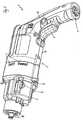
- a drill 1is shown as an example of a hand tool.
- the inventioncan also be used in another hand-held power tool such as a percussion drill or the like.
- the drilling machine 1has a housing 2 with a handle 6, which is integrally formed on a housing part 75. In the area of the handle 6, an actuating lever 8 is fixed.
- the drill 1has an electric motor, which can be supplied via a plug contact 5 on the handle 6 current.
- On the housing part 75is on the side facing away from the handle 6 of the gearbox 3 with three screws 11, two of which are shown in Fig. 1, fixed.
- gearbox 3On gearbox 3, a shift handle 9 is rotatably mounted.
- the switching handle 9has two switching positions, which are rotated against each other by 180 °.
- the gear box 3has ventilation slots 4 through which cooling air is conveyed by the fan wheel of the drilling machine 1.
- the engineis driving via a gearbox 3 arranged in the transmission, the spindle 10 to rotate.
- Fig. 2the transmission 7 is shown in perspective.
- the motor of the drill 1drives via a pinion and the fifth gear 17, the drive shaft 16 to rotate.
- On the drive shaft 16a third gear 14 and a fourth gear 15 is fixed, wherein the diameter of the fourth gear 15 is larger than that of the third gear 14.
- the third gear 14drives a first gear 12 in rotation and the fourth gear 15, a second gear 13.
- the second gear 13has a smaller diameter than the first gear 12.
- the first gear 12has holes 47 and the second gear 13 has holes 48. Between the gears 12 and 13, a switching disc 18 is arranged.
- the indexing disk 18has pins 37, not shown in FIG. 2, which are arranged at a radial distance from the axis of rotation of the spindle 10, which corresponds to the axis of rotation 52 of the gears 12 and 13, and which are aligned in the direction of the axis of rotation 52.
- the pins 37can protrude into the holes 47 and 48 and thereby connect the indexing disk 18 with the gear 12 and the gear 13 rotatably.
- the indexing disk 18is slidably mounted in the direction of the axis of rotation of the gears 12 and 13.
- a guide 19is provided, which passes through a bore 20 protrudes in the indexing disk 18.
- the indexing disk 18is held on two guides 19, which are arranged on both sides of the axis of rotation of the gears 12 and 13.
- the guides 19are held on the housing 2 and formed rod-shaped. 2, the indexing disk 18 is shown in a first switching position 29, in which it is rotatably connected to the first gear 12.
- the switching handle 9For switching between the two switching positions of the indexing disk 18, the switching handle 9 is provided.
- the switching handle 9protrudes with a pin 21 into the housing 2.
- the bolt 21has a circumferential groove 22, in whose groove bottom a cam contour is formed.
- a spring 23which rests on both sides of the cam contour and determines the cam contour switching positions of the control handle 9.
- the two switching positions of the control handle 9are rotated by 180 ° to each other.
- the switching handle 9actuates a suspension 24, via which the switching disk 18 between the first switching position 29 and a second switching position in the direction of the axis of rotation 52 of the gears 12 and 13 can be moved.
- the suspension 24is disposed radially outside the indexing disk 18 and the gears 12 and 13.
- the suspension 24is held on the housing 2 via a guide 36.
- the guide 36is rod-shaped.
- the guide 24has a first slider 27 and a second slider 28, between which a spring 35 is mounted.
- the spring 35is designed as a compression spring and arranged coaxially with the guide 36.
- the switching handle 9is about the axis of rotation 72 in the transmission housing, not shown in Fig. 3 3 rotatably mounted.
- the bolt 21has a seal 25 for sealing against the housing 2.
- a pin 26is formed on the pin 21.
- the pin 26is arranged eccentrically to the axis of rotation 72. The pin 26 protrudes into a gap between the two slides 27 and 28 and abuts a button 70 on a switching portion 40 on the first slider 27 and a button 71 on a switching portion 41 on the second slider 47.
- the second slider 28has a sliding surface 49 which bears against the gearbox 3 and over which the second slider 28 is guided in the longitudinal direction of the axis of rotation 52 of the gears 12 and 13.
- In the first switching position 29 shown in Fig. 3protrude from the side 69 of the indexing disk 18 three pins 37 in the direction of the second gear 13.
- On the opposite side 68 of the indexing disk 18protrude the driver 37 into the holes 47 in the first gear 12 and connect the indexing disk 18 rotatably connected to the first gear 12th
- the indexing disk 18is displaceably mounted on an output shaft 33 in the direction of the axis of rotation 52.
- the indexing disk 18is rotatably connected to the output shaft 33 via a toothing 34.
- the pins 37project beyond the end face 32 of the indexing disk 18 also.
- the pins 37protrude beyond the end face 31 into the bores 47 in the first gearwheel 12.
- the end faces 31, 32 of the indexing disk 18are the surfaces adjacent to the gearwheels 12, 13 in the switching positions 29, 30 are arranged.
- the Pins 37extend through the indexing disk 18 completely.
- the pin 26 on the control handle 9in its spindle 10 and the first gear 12 facing the handle 6 facing away from position.
- the pin 26presses the Switching portion 40 on the first slider 27 in the direction of the arrow 76, ie approximately in the direction of the handle 6 of the drill 1.
- the spring 35is compressed. The spring 35 presses on the pressure portion 43 of the second slider 28 in the direction of the arrow 76.
- the actuating portion 39 of the second slider 28which engages on the side 68 of the indexing disk 18, pushes the indexing disk 18 in the direction of the arrow 76 to the second gear 13 If the pins 37 are not congruent with the holes 48 in the second gear 13, the pins 37 are pressed against the end face 77 of the gear 13 and the spring 35 remains taut. Once the holes 48 are coaxially aligned with the drivers 37, the driver 37 engage in the holes 48 and the indexing disk 18 is pressed by the spring 35 against the second gear 13. About the suspension 24, the indexing disk 18 and the gear 13 are synchronized. On the first slider 27, a stop 46 is formed, against which the pressure portion 43 of the second slider 28 is applied.
- the stopper 46limits the maximum length of the compression spring 35 and thereby ensures that the pin 26 is not clamped by the force of the spring 35 between the switching portions 40 and 41 of the slide 27 and 28.
- the drivers 37are not aligned coaxially with the bores 47 in the first gearwheel 12, the drivers 37 initially abut on the front side 79 of the first gearwheel 12 until the first gearwheel 12 is further rotated until the drivers 37 engage in the bores 47 , While the driver 37 abut the end face 79, the spring 35 is tensioned, since the switching handle 9 is already in the position shown in Fig. 4, ie in its spindle 10 facing the end position.
- the actuating portion 38 of the first slider 27is located on the shoulder 44 at a distance from the end face 32 on the indexing disk 18.
- the actuating portion 39 of the second slider 28is located in the recess 45 shown in FIG. 4 on the indexing disk 18, so that the second slider 28 does not protrude beyond the end face 31 of the indexing disk 18.
- the suspension 24is shown.
- the second slider 28is substantially U-shaped.
- the sliding surface 49is formed on the bottom 65 of the U.
- On a first leg of the U of the actuating portion 39is formed, as shown in particular Fig. 9 shows.
- the printing section 43is arranged on the second leg of the U.
- the spring 35is arranged in the direction of a longitudinal axis 51.
- the longitudinal axis 51indicates the direction in which the suspension 24 acts.
- the abutment 46is arranged on the side of the pressure section 43 facing away from the spring 35 and is formed integrally with the first slider 27.
- the first slider 27extends in the region of the spring 35 approximately parallel to the longitudinal axis 51 and is rotated relative to the bottom 65 by 90 ° about the longitudinal axis 51.
- the switching section 40is formed (FIG. 7).
- the first slider 27is angled and extends parallel to the bottom 65 of the second slider 28.
- the actuating portion 38connects.
- the suspension 24has a through hole 80, shown in FIG. 8, through which the guide 36 protrudes.
- buttons 70 and 71which are parallel to each other and between which a gap 50 is formed, into which the pin 26 of the control handle 9 protrudes. When switching the switching handle 8, the pin 26 slides along the buttons 70 and 71 along.
- the indexing disk 18is shown.
- a driving deviceis integrated.
- the indexing disk 18has an outer ring 55 which has two oppositely disposed slots 81 on its outer periphery. At the slots 81 corresponding to the holes 20 shown in Fig. 2, the outer ring 55 is rotatably mounted on the housing 2 of the drill 1.
- the entrainment devicehas three roller pairs 60, which are each formed from two rollers 61. Between the two rollers 61 of a pair of rollers 60 each have a spring 59 is mounted. In the spring 59 is a ball 62 for limiting the distance by which the spring 59 can be compressed, arranged.
- the rollers 61are guided on the inner circumference 73 of the outer ring 55.
- the pairs of rollers 60are arranged between the outer ring 55 and an inner member 53, on the outer circumference 74 they rest against a cam contour 66.
- the cam contour 66is designed so that the distance of the cam contour 66 decreases to the axis of rotation 52 in the direction of the center 85 of the roller pair 60 and increases to the outside.
- the drive ring 54has, as shown in Fig. 14, holes 83 through which the pins 37 protrude.
- the pins 37are thus rotatably connected to the drive ring 54.
- the pins 37are arranged in recesses 84 on the outer circumference 74 of the inner element 53.
- the longitudinal central axis 67 of the pins 37has a distance a from the axis of rotation 52 (FIG. 12).
- the extent of the recesses 84 in the circumferential direction to the axis of rotation 52is greater than the diameter of the pins 37, so that the pins 37 are movable relative to the inner member 53 about the axis of rotation 52.
- the drive ring 54rests against the outer ring 55 on one side 69 and protrudes with its pressure pieces 56 into the outer ring 55.
- a disk 63is arranged on the outer ring 55.
- the pins 37are held on the disc 63 via snap rings 57.
- the disc 63can also be fixed in other ways, for example by welding or the like.
- the inner member 53has webs 64, the drive ring 54th project through. On the outer circumference of the webs 64, a damping element 58 is arranged.
Landscapes
- Engineering & Computer Science (AREA)
- Mechanical Engineering (AREA)
- Finish Polishing, Edge Sharpening, And Grinding By Specific Grinding Devices (AREA)
Description
Translated fromGermanDie Erfindung betrifft eine Handwerkzeugmaschine, insbesondere eine Bohrmaschine, eine Schlagbohrmaschine oder dergleichen der im Oberbetriff des Anspruchs 1 angegebenen Gattung.The invention relates to a hand tool, in particular a drill, a percussion drill or the like specified in the preamble of claim 1 genus.
Eine solche Handwerkzeugmaschine ist aus WO 93/15863 bekannt.Such a hand tool machine is known from WO 93/15863.
Bei Handwerkzeugmaschinen mit einem Getriebe mit mehreren Gängen ist es bekannt, daß eine Schaltscheibe vorgesehen ist, mit der zwischen den Gängen des Getriebes umgeschaltet werden kann. Zur drehfesten Verbindung der Schaltscheibe mit einem Zahnrad sind dabei üblicherweise Mitnehmer vorgesehen. Beim Umschalten muß die Stellung der Schaltscheibe und die des Zahnrads so aufeinander abgestimmt werden, daß der Mitnehmer in Eingriff mit dem Zahnrad bzw. mit der Schaltscheibe kommen kann. Bei bekannten Handwerkzeugmaschinen sind die Mitnehmer in Richtung der Drehachse der Zahnräder in der Schaltscheibe gefedert gelagert. Die Schaltscheibe wird bis an ein Zahnrad gedrückt, wodurch die Federn der Mitnehmer bei Anlage der Mitnehmer an der Stirnseite des Zahnrads gespannt werden. Beim Weiterdrehen des Zahnrads kommen die Mitnehmer deckungsgleich über für die Mitnehmer vorgesehene Öffnungen zu liegen und rasten aufgrund der Federung in die Öffnungen ein, so daß die Schaltscheibe mit dem Zahnrad drehfest verbunden ist. Die Federung der einzelnen Mitnehmer ist in der Montage aufwendig. Aufgrund der Federung ist die Baugröße der Schaltscheibe relativ groß. Insbesondere in Richtung der Drehachse kann die Baugröße der Schaltscheibe nicht verringert werden. Üblicherweise sind mehrere, insbesondere drei Mitnehmer vorgesehen. Dabei muß für jeden Mitnehmer eine separate Federung vorgesehen werden.In hand tool machines with a gearbox with multiple gears, it is known that a switching disc is provided, can be switched with the between the gears of the transmission. For rotationally fixed connection of the indexing disk with a gear usually drivers are provided. When switching the position of the indexing disk and the gear must be coordinated so that the driver can come into engagement with the gear or with the switching disk. In known hand tool machines, the drivers are spring-mounted in the direction of the axis of rotation of the gears in the indexing disk. The indexing disk is pressed to a gear, whereby the springs of the driver are clamped when the driver on the front side of the gear. Upon further rotation of the gear, the drivers are congruent to be provided for the driver openings provided and engage due to the suspension in the openings, so that the switching disc is rotatably connected to the gear. The suspension of the individual drivers is expensive in the assembly. Due to the suspension, the size of the indexing disk is relatively large. Especially in the direction of the axis of rotation can Size of the switching disc can not be reduced. Usually, several, in particular three drivers are provided. It must be provided for each driver a separate suspension.
Aus der WO 93/15863 ist eine Handwerkzeugmaschine bekannt, bei der der Schaltgriff über eine Feder auf einen Schieber wirkt, der zwischen den Gängen schaltet. Beim Umschalten wird der Schaltgriff mit der im Schaltgriff gelagerten Druckfeder um 180° gedreht, so daß der Schaltgriff nun auf den gegenüberliegenden Schenkel des U-förmig ausgebildeten Schiebers wirkt.From WO 93/15863 a hand tool is known, in which the switching handle acts via a spring on a slider which switches between the gears. When switching the handle is rotated by the pressure spring mounted in the control handle by 180 °, so that the control handle now acts on the opposite leg of the U-shaped slide.
Aus der DE 25 11 469 A1 ist eine Schaltvorrichtung für eine Handwerkzeugmaschine bekannt, bei der der Schaltgriff direkt auf eine Schaltscheibe wirkt und diese zwischen zwei bzw. drei Schaltstellungen verstellt. Die Schaltscheibe ist dabei gegenüber dem Gehäuse gefedert gelagert.From DE 25 11 469 A1 discloses a switching device for a hand tool is known in which the switching handle acts directly on a switching disc and this adjusted between two or three switch positions. The indexing disk is mounted sprung relative to the housing.
Aus der DE 39 04 085 A1 ist eine Einrichtung zum Umschalten des Getriebes eines Elektrowerkzeugs bekannt, bei dem ein Schaltschieber über ein bügelförmiges Federelement auf ein Kunststoffzahnrad wirkt und dieses zwischen zwei Schaltstellungen verschiebt.From DE 39 04 085 A1 discloses a device for switching the transmission of a power tool is known in which a slide switch acts via a bow-shaped spring element on a plastic gear and this shifts between two switching positions.
Der Erfindung liegt die Aufgabe zugrunde, eine Handwerkzeugmaschine der gattungsgemäßen Art zu schaffen, deren Getriebe einen einfachen Aufbau und eine geringe Baugröße besitzt.The invention has for its object to provide a hand tool of the generic type, the transmission has a simple structure and a small size.
Diese Aufgabe wird durch eine Handwerkzeugmaschine mit den Merkmalen des Anspruchs 1 gelöst.This object is achieved by a hand tool with the features of claim 1.
Dadurch, daß die Schaltvorrichtung über eine Federung auf die Schaltscheibe wirkt, ist eine Federung der einzelnen Mitnehmer nicht mehr notwendig. Da nicht jeder Mitnehmer separat gefedert wird, ist nur eine Feder für die Federung notwendig.The fact that the switching device acts via a suspension on the indexing plate, a suspension of the individual drivers is no longer necessary. Since not every driver is sprung separately, only one spring is necessary for the suspension.
Es ist vorgesehen, daß die Federung außerhalb der Schaltscheibe angeordnet ist. Dadurch kann die Schaltscheibe schmaler ausgebildet werden. Die Baulänge der Handwerkzeugmaschine in Richtung der Drehachse wird dadurch verringert. Da die Federung nicht in die Schaltscheibe integriert ist, ist die Montage vereinfacht. Die Federung ist insbesondere radial außerhalb der Schaltscheibe angeordnet. Dadurch kann die Baulänge der Handwerkzeugmaschine in Richtung der Drehachse verkleinert werden.It is envisaged that the suspension is arranged outside the indexing disk. As a result, the indexing disk can be made narrower. The overall length of the power tool in the direction of the axis of rotation is thereby reduced. Since the suspension is not integrated in the switching disc, the assembly is simplified. The suspension is arranged in particular radially outside the indexing disk. As a result, the overall length of the power tool in the direction of the axis of rotation can be reduced.
Zweckmäßig umfaßt die Federung eine Feder, die zwischen zwei in Richtung der Drehachse beweglichen Schiebern gelagert ist. Vorteilhaft besitzt ein erster Schieber einen Betätigungsabschnitt, der auf eine Seite der Schaltscheibe wirkt und einen Druckabschnitt, an dem die Feder angreift. Es ist vorgesehen, daß ein zweiter Schieber einen Schaltabschnitt, auf den die Schaltvorrichtung wirkt, und einen Druckabschnitt, an dem die Feder angreift, besitzt. Über die Schaltvorrichtung wird der zweite Schieber über seinen Schaltabschnitt in Richtung der Drehachse des Zahnrads verschoben. Über seinen Druckabschnitt wirkt der Schieber auf die Feder. Am zweiten Ende der Feder ist der Druckabschnitt des ersten Schiebers angeordnet, der mit seinem Betätigungsabschnitt auf eine Seite der Schaltscheibe wirkt. Der Betätigungsabschnitt des zweiten Schiebers drückt somit auf die Schaltscheibe, bis diese mit ihrem Mitnehmer am Zahnrad einrastet. Vorteilhaft ist die Feder eine Druckfeder. Zweckmäßig sind die Feder und die Schieber an einer gehäusefesten Führung gelagert. Hierdurch kann sichergestellt werden, daß die Schieber nur in Richtung der Drehachse beweglich sind. Ein Verkanten der Schieber kann hierdurch vermieden werden. Eine zusätzliche Führung kann dadurch gebildet werden, daß an einem Schieber eine Gleitfläche ausgebildet ist, mit der sich der Schieber am Gehäuse abstützt.Suitably, the suspension comprises a spring which is mounted between two movable in the direction of the axis of rotation slides. Advantageously, a first slider has an actuating portion which acts on one side of the indexing disk and a pressure portion on which the spring engages. It is envisaged that a second slider has a switching portion, on which the switching device acts, and a pressure portion, which acts on the spring has. About the switching device, the second slider is moved over its switching portion in the direction of the axis of rotation of the gear. About its pressure section, the slider acts on the spring. At the second end of the spring, the pressure portion of the first slider is arranged, which acts with its operating portion on one side of the switching disk. The operating portion of the second slider thus presses on the indexing disc until it engages with its driver on the gear. Advantageously, the spring is a compression spring. Suitably, the spring and the slide are mounted on a guide fixed to the housing. In this way it can be ensured that the slides are movable only in the direction of the axis of rotation. A tilting of the slide can be avoided thereby. An additional guide can be formed in that on a slider, a sliding surface is formed, with which the slider is supported on the housing.
Um die Schaltscheibe in beide Richtungen zu federn, sind zwei Schieber vorgesehen, wobei jeder Schieber einen Betätigungsabschnitt, einen Druckabschnitt und einen Schaltabschnitt besitzt. Je nach Verschieberichtung sind der Betätigungsabschnitt und der Druckabschnitt von einem und der Druckabschnitt und der Schaltabschnitt von dem anderen Schieber im Einsatz. Vorteilhaft ist zwischen den Schaltabschnitten der beiden Schieber ein Spalt gebildet, in den ein Zapfen der Schaltvorrichtung greift. Hierdurch können die Schieber auf einfache Weise verschoben werden. Die Schaltvorrichtung umfaßt zweckmäßig ein drehbar gelagertes Schaltelement und einen Zapfen, wobei der Zapfen exzentrisch zur Drehachse des Schaltelements angeordnet ist. Durch Drehung des Schaltelements bewegt sich der Zapfen in dem Spalt zwischen den Schaltabschnitten der beiden Schieber in Richtung der Drehachse und in einer Richtung senkrecht hierzu. Zweckmäßig besitzt der Schaltabschnitt eine etwa senkrecht zur Drehachse des Schaltelements ausgerichtete Schaltfläche.In order to spring the switch disc in both directions, two slides are provided, each slider having an operating portion, a pressure portion and a switching portion. Depending on the direction of displacement, the actuating portion and the pressure portion of one and the pressure portion and the switching portion of the other slider in use. Advantageously, a gap is formed between the switching sections of the two slides, in which engages a pin of the switching device. As a result, the slides can be easily moved. The switching device suitably comprises a rotatably mounted switching element and a pin, wherein the pin is arranged eccentrically to the axis of rotation of the switching element. By rotation of the switching element, the pin moves in the gap between the switching sections of the two slides in the direction of the axis of rotation and in a direction perpendicular thereto. Suitably, the switching section has an approximately perpendicular to the axis of rotation of the switching element aligned button.
Um ein Umschalten zwischen zwei Gängen des Getriebes zu ermöglichen, ist vorgesehen, daß die Schaltscheibe in der ersten Schaltstellung mit einem ersten Zahnrad und in der zweiten Schaltstellung mit einem zweiten Zahnrad verbunden ist. Der Mitnehmer ist dabei insbesondere an der Schaltscheibe angeordnet. Vorteilhaft durchragt der Mitnehmer die Schaltscheibe und steht an beiden Seiten der Schaltscheibe über die Stirnseiten der Schaltscheibe über. Ein Mitnehmer kann dadurch sowohl mit dem einen als auch mit dem anderen Zahnrad eine drehfeste Verbindung herstellen. Eine einfache Ausgestaltung ergibt sich, wenn der Mitnehmer ein Stift ist. Um eine gute Drehmomentübertragung zu erreichen, ist vorgesehen, daß drei Mitnehmer an der Schaltscheibe festgelegt sind.In order to enable switching between two gears of the transmission, it is provided that the indexing disk is connected in the first switching position with a first gear and in the second switching position with a second gear. The driver is arranged in particular on the indexing disk. Advantageously, the driver projects through the indexing disk and projects beyond the end faces of the indexing disk on both sides of the indexing disk. A driver can thereby produce a rotationally fixed connection with both the one and the other gear. A simple embodiment results when the driver is a pin. In order to achieve a good torque transmission, it is provided that three drivers are fixed to the switching disc.
Vorteilhaft besitzt die Schaltscheibe eine Mitnahmevorrichtung, die ein Drehmoment von den Mitnehmern auf die Abtriebswelle des Getriebes überträgt und bei einem Drehmoment von der Abtriebswelle die Abtriebswelle blockiert. Derartige Mitnahmevorrichtungen werden bei Handwerkzeugmaschinen eingesetzt, um ein einfaches Lösen eines Werkzeuges zu ermöglichen. Da die Spindel durch die Mitnahmevorrichtung beim Drehen an der Spindel automatisch blockiert, kann ein an der Spindel festgelegtes Werkzeug gelöst werden, ohne daß die Spindel mitdreht. Ein Drehmoment vom Motor, das über das Getriebe auf die Mitnehmer der Schaltscheibe übertragen wird, wird über die Mitnahmevorrichtung auf die Abtriebswelle und die Spindel übertragen. Durch die Federung der gesamten Schaltscheibe ist in der Schaltscheibe ausreichend Bauraum vorhanden, um die Mitnahmevorrichtung zu integrieren. Vorteilhaft besitzt die Schaltscheibe einen Außenring, der am Gehäuse der Handwerkzeugmaschine drehfest gehalten ist. Die Schaltscheibe besitzt zweckmäßig ein Innenelement, das mit der Abtriebswelle über eine Verzahnung drehfest verbunden ist. Insbesondere besitzt die Schaltscheibe einen Antriebsring, der mit den Mitnehmern drehfest verbunden ist. Vorteilhaft umfaßt die Mitnahmevorrichtung mindestens ein Rollenpaar, wobei die beiden Rollen des Rollenpaars in Umfangsrichtung zur Drehachse benachbart zueinander angeordnet sind und am Innenumfang des Außenrings und an einer am Außenumfang des Innenelements gebildeten Nockenkontur anliegen, wobei zwischen den Rollen eine Feder angeordnet ist. Vorteilhaft sind in Umfangsrichtung zur Drehachse benachbart zu dem Rollenpaar Druckstücke angeordnet, die drehfest mit dem Antriebsring verbunden sind.Advantageously, the indexing disk has a driving device, the torque from the drivers to the output shaft transmits the transmission and blocked at a torque from the output shaft, the output shaft. Such entrainment devices are used in portable power tools to allow easy release of a tool. Since the spindle is automatically blocked by the driving device when turning on the spindle, a fixed to the spindle tool can be solved without the spindle rotates. A torque from the engine, which is transmitted via the gear on the driver of the indexing disk is transmitted via the driving device to the output shaft and the spindle. Due to the suspension of the entire switching disk, sufficient space is available in the indexing disk to integrate the driving device. Advantageously, the indexing disk has an outer ring, which is held against rotation on the housing of the power tool. The switching disk expediently has an inner element which is connected in a rotationally fixed manner to the output shaft via a tooth system. In particular, the switching disk has a drive ring which is rotatably connected to the drivers. Advantageously, the driving device comprises at least one pair of rollers, wherein the two rollers of the pair of rollers are arranged adjacent to each other in the circumferential direction to the axis of rotation and bear against the inner circumference of the outer ring and on a cam contour formed on the outer circumference of the inner member, wherein between the rollers, a spring is arranged. Adjacent to the pair of rollers are arranged in the circumferential direction to the rotation axis pressure pieces, which are rotatably connected to the drive ring in the circumferential direction.
Ein Ausführungsbeispiel der Erfindung wird im folgenden anhand der Zeichnung erläutert. Es zeigen:
- Fig. 1
- eine perspektivische Darstellung einer Bohrmaschine,
- Fig. 2
- eine perspektivische Darstellung des Getriebes einer Bohrmaschine in einer ersten Schaltstellung,
- Fig. 3
- eine Seitenansicht auf das Getriebe aus Fig. 2 in Richtung des Pfeils III in Fig. 2,
- Fig. 4
- eine Seitenansicht auf das Getriebe aus Fig. 3 in Richtung des Pfeils IV in Fig. 3,
- Fig. 5
- das Getriebe aus Fig. 4 in einer zweiten Schaltstellung,
- Fig. 6
- eine perspektivische Darstellung einer Federung,
- Fig. 7
- eine Seitenansicht der Federung aus Fig. 6,
- Fig. 8
- eine Ansicht auf die Federung in Richtung des Pfeils VIII in Fig. 9,
- Fig. 9
- eine Seitenansicht auf die Federung in Richtung des Pfeils IX in Fig. 7,
- Fig. 10
- eine Seitenansicht auf die Federung in Richtung des Pfeils X in Fig. 9,
- Fig. 11
- eine Seitenansicht einer Schaltscheibe,
- Fig. 12
- einen Schnitt durch die Schaltscheibe entlang der Linie XII-XII in Fig. 11,
- Fig. 13
- einen Schnitt durch die Schaltscheibe in Richtung der Linie XIII-XIII in Fig. 12,
- Fig. 14
- die Schaltscheibe aus den Fig. 11
bis 13 in Explosionsdarstellung.
- Fig. 1
- a perspective view of a drill,
- Fig. 2
- a perspective view of the transmission of a drill in a first switching position,
- Fig. 3
- 2 is a side view of the transmission from FIG. 2 in the direction of the arrow III in FIG. 2, FIG.
- Fig. 4
- 3 is a side view of the transmission from FIG. 3 in the direction of the arrow IV in FIG. 3, FIG.
- Fig. 5
- the transmission of FIG. 4 in a second switching position,
- Fig. 6
- a perspective view of a suspension,
- Fig. 7
- a side view of the suspension of FIG. 6,
- Fig. 8
- a view of the suspension in the direction of arrow VIII in Fig. 9,
- Fig. 9
- a side view of the suspension in the direction of arrow IX in Fig. 7,
- Fig. 10
- a side view of the suspension in the direction of the arrow X in Fig. 9,
- Fig. 11
- a side view of a switching disc,
- Fig. 12
- a section through the switching disk along the line XII-XII in Fig. 11,
- Fig. 13
- a section through the indexing disk in the direction of line XIII-XIII in Fig. 12,
- Fig. 14
- the switching disk of FIGS. 11 to 13 in an exploded view.
In Fig. 1 ist als Beispiel für eine Handwerkzeugmaschine eine Bohrmaschine 1 dargestellt. Anstatt der Bohrmaschine kann die Erfindung auch bei einer anderen Handwerkzeugmaschine wie beispielsweise einer Schlagbohrmaschine oder dergleichen zum Einsatz kommen. Die Bohrmaschine 1 besitzt ein Gehäuse 2 mit einem Griff 6, der an einem Gehäuseteil 75 angeformt ist. Im Bereich des Griffs 6 ist ein Betätigungshebel 8 festgelegt. Die Bohrmaschine 1 besitzt einen Elektromotor, dem über einen Steckkontakt 5 am Griff 6 Strom zugeführt werden kann. Am Gehäuseteil 75 ist an der dem Griff 6 abgewandten Seite der Getriebekasten 3 mit drei Schrauben 11, von denen zwei in Fig. 1 gezeigt sind, festgelegt. Am Getriebekasten 3 ist ein Schaltgriff 9 drehbar gelagert. Der Schaltgriff 9 besitzt zwei Schaltpositionen, die gegeneinander um 180° gedreht sind. An der dem Gehäuseteil 75 zugewandten Seite besitzt der Getriebekasten 3 Lüftungsschlitze 4, durch die vom Lüfterrad der Bohrmaschine 1 Kühlluft gefördert wird. Der Motor treibt über ein im Getriebekasten 3 angeordnetes Getriebe die Spindel 10 rotierend an.In Fig. 1, a drill 1 is shown as an example of a hand tool. Instead of the drilling machine, the invention can also be used in another hand-held power tool such as a percussion drill or the like. The drilling machine 1 has a
In Fig. 2 ist das Getriebe 7 perspektivisch dargestellt. Der Motor der Bohrmaschine 1 treibt über ein Ritzel und über das fünfte Zahnrad 17 die Antriebswelle 16 rotierend an. Auf der Antriebswelle 16 ist ein drittes Zahnrad 14 und ein viertes Zahnrad 15 festgelegt, wobei der Durchmesser des vierten Zahnrads 15 größer als der des dritten Zahnrads 14 ist. Das dritte Zahnrad 14 treibt ein erstes Zahnrad 12 rotierend an und das vierte Zahnrad 15 ein zweites Zahnrad 13. Das zweite Zahnrad 13 besitzt einen kleineren Durchmesser als das erste Zahnrad 12. Bei einer Übertragung des Drehmoments von der Antriebswelle 16 über die Zahnräder 14 und 12 ergibt sich somit eine kleinere Übersetzung als bei einer Übertragung über die Zahnräder 15 und 13, wobei die Zahnräder 12 und 13 größer als die Zahnräder 14 und 15 sind und sich somit die Zahnräder 12 und 13 schneller als die Antriebswelle 16 drehen. Das erste Zahnrad 12 besitzt Bohrungen 47 und das zweite Zahnrad 13 besitzt Bohrungen 48. Zwischen den Zahnrädern 12 und 13 ist eine Schaltscheibe 18 angeordnet. Die Schaltscheibe 18 besitzt in Fig. 2 nicht gezeigte Stifte 37, die in radialem Abstand zur Drehachse der Spindel 10, die der Drehachse 52 der Zahnräder 12 und 13 entspricht, angeordnet sind und die in Richtung der Drehachse 52 ausgerichtet sind. Die Stifte 37 können in die Bohrungen 47 bzw. 48 ragen und dadurch die Schaltscheibe 18 mit dem Zahnrad 12 bzw. dem Zahnrad 13 drehfest verbinden. Die Schaltscheibe 18 ist in Richtung der Drehachse der Zahnräder 12 und 13 verschieblich gelagert. Hierzu ist eine Führung 19 vorgesehen, die durch eine Bohrung 20 in der Schaltscheibe 18 ragt. Die Schaltscheibe 18 ist dabei an zwei Führungen 19 gehalten, die beidseitig der Drehachse der Zahnräder 12 und 13 angeordnet sind. Die Führungen 19 sind am Gehäuse 2 gehalten und stabförmig ausgebildet. In Fig. 2 ist die Schaltscheibe 18 in einer ersten Schaltstellung 29 dargestellt, in der sie drehfest mit dem ersten Zahnrad 12 verbunden ist.In Fig. 2, the
Zum Umschalten zwischen den beiden Schaltstellungen der Schaltscheibe 18 ist der Schaltgriff 9 vorgesehen. Der Schaltgriff 9 ragt mit einem Bolzen 21 ins Gehäuse 2. Der Bolzen 21 besitzt eine umlaufende Nut 22, in deren Nutgrund eine Nockenkontur ausgebildet ist. In die Nut 22 ragt eine Feder 23, die beidseitig an der Nockenkontur anliegt und mit der Nockenkontur Schaltpositionen des Schaltgriffs 9 festlegt. Die beiden Schaltpositionen des Schaltgriffs 9 sind dabei um 180° zueinander gedreht. Der Schaltgriff 9 betätigt eine Federung 24, über die die Schaltscheibe 18 zwischen der ersten Schaltstellung 29 und einer zweiten Schaltstellung in Richtung der Drehachse 52 der Zahnräder 12 und 13 verschoben werden kann. Die Federung 24 ist radial außerhalb der Schaltscheibe 18 und der Zahnräder 12 und 13 angeordnet. Die Federung 24 ist über eine Führung 36 am Gehäuse 2 gehalten. Die Führung 36 ist stabförmig ausgebildet. Die Führung 24 besitzt einen ersten Schieber 27 und einen zweiten Schieber 28, zwischen denen eine Feder 35 gelagert ist. Die Feder 35 ist als Druckfeder ausgebildet und koaxial zur Führung 36 angeordnet.For switching between the two switching positions of the
Wie die Seitenansicht in Fig. 3 zeigt, ist der Schaltgriff 9 um die Drehachse 72 im in Fig. 3 nicht gezeigten Getriebegehäuse 3 drehbar gelagert. Der Bolzen 21 besitzt eine Dichtung 25 zur Abdichtung gegenüber dem Gehäuse 2. Auf der der Federung 24 zugewandten Seite ist am Bolzen 21 ein Zapfen 26 angeformt. Der Zapfen 26 ist exzentrisch zur Drehachse 72 angeordnet. Der Zapfen 26 ragt in einen Spalt zwischen den beiden Schiebern 27 und 28 und liegt an einer Schaltfläche 70 an einem Schaltabschnitt 40 am ersten Schieber 27 und an einer Schaltfläche 71 an einem Schaltabschnitt 41 am zweiten Schieber 47 an. Der zweite Schieber 28 besitzt eine Gleitfläche 49, die am Getriebekasten 3 anliegt und über die der zweite Schieber 28 in Längsrichtung der Drehachse 52 der Zahnräder 12 und 13 geführt ist. In der in Fig. 3 gezeigten ersten Schaltstellung 29 ragen von der Seite 69 der Schaltscheibe 18 drei Stifte 37 in Richtung auf das zweite Zahnrad 13. Auf der gegenüberliegenden Seite 68 der Schaltscheibe 18 ragen die Mitnehmer 37 in die Bohrungen 47 im ersten Zahnrad 12 und verbinden so die Schaltscheibe 18 drehfest mit dem ersten Zahnrad 12.As the side view in Fig. 3 shows, the switching handle 9 is about the axis of
Wie Fig. 4 zeigt, ist die Schaltscheibe 18 auf einer Abtriebswelle 33 in Richtung der Drehachse 52 verschieblich gelagert. Die Schaltscheibe 18 ist dabei über eine Verzahnung 34 drehfest mit der Abtriebswelle 33 verbunden. An der dem zweiten Zahnrad 13 zugewandten Seite 69 der Schaltscheibe 18 ragen die Stifte 37 über die Stirnseite 32 der Schaltscheibe 18 hinaus. Auf der gegenüberliegenden Seite 68 ragen die Stifte 37 über die Stirnseite 31 in die Bohrungen 47 im ersten Zahnrad 12. Die Stirnseiten 31, 32 der Schaltscheibe 18 sind dabei die Flächen, die in den Schaltstellungen 29, 30 benachbart zu den Zahnrädern 12 bzw. 13 angeordnet sind. Die Stifte 37 durchragen die Schaltscheibe 18 vollständig. In der ersten Schaltstellung 29 ist der Zapfen 26 am Schaltgriff 9 in seiner der Spindel 10 bzw. dem ersten Zahnrad 12 zugewandten, dem Griff 6 abgewandten Position. Beim Drehen des Schaltgriffs 9 von der in Fig. 4 gezeigten zu der in Fig. 5 gezeigten Schaltposition, in der der Zapfen 26 in seiner der Spindel 10 abgewandten, dem Griff 6 und dem ersten Zahnrad 13 zugewandten Position ist, drückt der Zapfen 26 den Schaltabschnitt 40 am ersten Schieber 27 in Richtung des Pfeils 76, also etwa in Richtung auf den Handgriff 6 der Bohrmaschine 1. Über den Druckabschnitt 42 des ersten Schiebers 27 wird die Feder 35 zusammengedrückt. Die Feder 35 drückt auf den Druckabschnitt 43 des zweiten Schiebers 28 in Richtung des Pfeils 76. Dadurch drückt der Betätigungsabschnitt 39 des zweiten Schiebers 28, der an der Seite 68 der Schaltscheibe 18 angreift, die Schaltscheibe 18 in Richtung des Pfeils 76 zum zweiten Zahnrad 13. Liegen die Stifte 37 nicht deckungsgleich zu den Bohrungen 48 im zweiten Zahnrad 13, werden die Stifte 37 gegen die Stirnseite 77 des Zahnrads 13 gedrückt und die Feder 35 bleibt gespannt. Sobald die Bohrungen 48 zu den Mitnehmern 37 koaxial ausgerichtet sind, rasten die Mitnehmer 37 in die Bohrungen 48 ein und die Schaltscheibe 18 wird von der Feder 35 gegen das zweite Zahnrad 13 gedrückt. Über die Federung 24 werden die Schaltscheibe 18 und das Zahnrad 13 so synchronisiert. Am ersten Schieber 27 ist ein Anschlag 46 angeformt, an dem der Druckabschnitt 43 des zweiten Schiebers 28 anliegt. Der Anschlag 46 begrenzt die maximale Länge der Druckfeder 35 und stellt dadurch sicher, daß der Zapfen 26 durch die Kraft der Feder 35 nicht zwischen den Schaltabschnitten 40 und 41 der Schieber 27 und 28 festgeklemmt wird. Beim Umschalten von der in Fig. 5 gezeigten zweiten Schaltstellung 30 in die erste Schaltstellung 29 wird der Zapfen 26 in Richtung des Pfeils 78 bewegt. Der Zapfen 26 drückt den Schaltabschnitt 41 in Richtung des Pfeils 78. Der zweite Schieber 28 wird dadurch in Richtung des Pfeils 78 bewegt. Über den Druckabschnitt 43 wird die Feder 35 gespannt. Die Feder 35 wirkt auf den Druckabschnitt 42 des ersten Schiebers 27, der mit seinem Betätigungsabschnitt 38 an einem Absatz 44 an der Seite 69 der Schaltscheibe 18 anliegt und die Schaltscheibe 18 in Richtung auf das erste Zahnrad 12 drückt. Sind die Mitnehmer 37 nicht koaxial zu den Bohrungen 47 im ersten Zahnrad 12 ausgerichtet, liegen die Mitnehmer 37 zunächst an der Stirnseite 79 des ersten Zahnrads 12 an, bis das erste Zahnrad 12 so weit weitergedreht ist, bis die Mitnehmer 37 in die Bohrungen 47 einrasten. Während die Mitnehmer 37 an der Stirnseite 79 anliegen, ist die Feder 35 gespannt, da der Schaltgriff 9 bereits in der in Fig. 4 gezeigten Position, also in seiner der Spindel 10 zugewandten Endposition ist. Um eine vollständige Anlage der Schaltscheibe 18 an die Zahnräder 13 und 12 zu ermöglichen, liegt der Betätigungsabschnitt 38 des ersten Schiebers 27 am Absatz 44 in einem Abstand zur Stirnseite 32 an der Schaltscheibe 18 an. Der Betätigungsabschnitt 39 des zweiten Schiebers 28 liegt in der in Fig. 4 gezeigten Aussparung 45 an der Schaltscheibe 18 an, so daß der zweite Schieber 28 nicht über die Stirnseite 31 der Schaltscheibe 18 heraussteht.As shown in FIG. 4, the
In den Fig. 6 bis 10 ist die Federung 24 gezeigt. Wie insbesondere Fig. 6 zeigt, ist der zweite Schieber 28 im wesentlichen U-förmig ausgebildet. Die Gleitfläche 49 ist dabei am Boden 65 des U ausgebildet. An einem ersten Schenkel des U ist der Betätigungsabschnitt 39 ausgebildet, wie insbesondere Fig. 9 zeigt. Am zweiten Schenkel des U ist der Druckabschnitt 43 angeordnet. Im Inneren des U ist die Feder 35 in Richtung einer Längsachse 51 angeordnet. Die Längsachse 51 bezeichnet dabei die Richtung, in der die Federung 24 wirkt. Wie insbesondere Fig. 10 zeigt, ist an der der Feder 35 abgewandten Seite des Druckabschnitts 43 der Anschlag 46 angeordnet, der einteilig mit dem ersten Schieber 27 ausgebildet ist. Der erste Schieber 27 verläuft im Bereich der Feder 35 etwa parallel zur Längsachse 51 und ist gegenüber dem Boden 65 um 90° um die Längsachse 51 gedreht. An dem parallel zur Längsachse 51 verlaufenden Abschnitt ist der Schaltabschnitt 40 angeformt (Fig. 7). Im Bereich des Schaltabschnitts 40 ist der erste Schieber 27 abgewinkelt und verläuft parallel zum Boden 65 des zweiten Schiebers 28. An dem abgewinkelten Abschnitt ist der Druckabschnitt 42 angeformt, der senkrecht zur Längsachse 51 verläuft (Fig. 9). An den Druckabschnitt 42 schließt sich der Betätigungsabschnitt 38 an. Im Bereich der Längsachse 51 besitzt die Federung 24 eine in Fig. 8 gezeigte durchgehende Bohrung 80, durch die die Führung 36 ragt. An den Schaltabschnitten 40 und 41 sind Schaltflächen 70 und 71 ausgebildet, die parallel zueinander verlaufen und zwischen denen ein Spalt 50 gebildet ist, in den der Zapfen 26 des Schaltgriffs 9 ragt. Beim Umschalten des Schaltgriffs 8 gleitet der Zapfen 26 an den Schaltflächen 70 und 71 entlang.In Figs. 6 to 10, the
In den Fig. 11 bis 14 ist die Schaltscheibe 18 dargestellt. In die Schaltscheibe 18 ist eine Mitnahmevorrichtung integriert. Die Schaltscheibe 18 besitzt einen Außenring 55, der an seinem Außenumfang zwei gegenüberliegend angeordnete Schlitze 81 besitzt. An den Schlitzen 81, die den in Fig. 2 gezeigten Bohrungen 20 entsprechen, ist der Außenring 55 am Gehäuse 2 der Bohrmaschine 1 drehfest gelagert. Wie Fig. 12 zeigt, besitzt die Mitnahmevorrichtung drei Rollenpaare 60, die aus jeweils zwei Rollen 61 gebildet sind. Zwischen den beiden Rollen 61 eines Rollenpaares 60 ist jeweils eine Feder 59 gelagert. In der Feder 59 ist eine Kugel 62 zur Begrenzung des Wegs, um den die Feder 59 zusammengedrückt werden kann, angeordnet. Die Rollen 61 sind am Innenumfang 73 des Außenrings 55 geführt. Die Rollenpaare 60 sind dabei zwischen dem Außenring 55 und einem Innenelement 53 angeordnet, an dessen Außenumfang 74 sie an einer Nockenkontur 66 anliegen. Die Nockenkontur 66 ist dabei so ausgebildet, daß der Abstand der Nockenkontur 66 zur Drehachse 52 in Richtung auf den Mittelpunkt 85 des Rollenpaars 60 abnimmt und nach außen zunimmt.In FIGS. 11 to 14, the
Zwischen den Rollenpaaren 60 sind Druckstücke 56 angeordnet, die mit einem Antriebsring 54 drehfest verbunden sind. Der Antriebsring 54 besitzt, wie in Fig. 14 gezeigt, Bohrungen 83, durch die die Stifte 37 ragen. Die Stifte 37 sind somit mit dem Antriebsring 54 drehfest verbunden. Die Stifte 37 sind in Ausnehmungen 84 am Außenumfang 74 des Innenelements 53 angeordnet. Die Längsmittelachse 67 der Stifte 37 besitzt dabei zur Drehachse 52 einen Abstand a (Fig. 12). Die Erstreckung der Ausnehmungen 84 in Umfangsrichtung zur Drehachse 52 ist größer als der Durchmesser der Stifte 37, so daß die Stifte 37 gegenüber dem Innenelement 53 um die Drehachse 52 beweglich sind.Between the pairs of
Bei einer Drehung der Abtriebswelle 33 wird die Drehung über die Verzahnung 34 der Abtriebswelle 33 und eine Verzahnung 82 am Innenelement 53 auf das Innenelement 53 übertragen. Das Innenelement 53 wird um die Drehachse 52 gedreht. Dabei wird eine Kugel 61 jedes Rollenpaars 60 in Richtung auf den Mittelpunkt 85 des Rollenpaars 60 zubewegt und die andere Rolle 61 vom Mittelpunkt 85 weg an den Rand. Da der Abstand der Nockenkontur 66 zum Innenumfang 73 des Außenrings 55 in Richtung auf den Rand des Rollenpaars 60 abnimmt, wird eine Rolle 61 zwischen dem Innenelement 53 und dem Außenring 55 eingeklemmt. Das Innenelement 53 wird dadurch blockiert. Beim Drehen der Mitnehmer 37 und damit des Antriebsrings 54 wird jeweils eine Rolle 61 eines Rollenpaars 60 von einem Druckstück 56 in Richtung auf den Mittelpunkt 85 des Rollenpaars 60 gedrückt. Ein Einklemmen einer Rolle 61 ist hierdurch vermieden, so daß der Antriebsring 54 nicht blockiert wird. Der Antriebsring 54 kann sich frei drehen, bis die Stifte 37 am Rand der Ausnehmung 84 anliegen und dadurch das Innenelement 53 mitnehmen. Das Drehmoment von den Stiften 37 wird dadurch auf das Innenelement 53 übertragen.Upon rotation of the
Wie die Fig. 13 und 14 zeigen, liegt der Antriebsring 54 an einer Seite 69 am Außenring 55 an und ragt mit seinen Druckstücken 56 in den Außenring 55. Auf der gegenüberliegenden Seite 68 ist am Außenring 55 eine Scheibe 63 angeordnet. Die Stifte 37 sind über Sprengringe 57 an der Scheibe 63 gehalten. Die Scheibe 63 kann jedoch auch auf andere Weise fixiert werden, beispielsweise durch Anschweißen oder dergleichen. Das Innenelement 53 besitzt Stege 64, die den Antriebsring 54 durchragen. Am Außenumfang der Stege 64 ist ein Dämpfungselement 58 angeordnet.As shown in FIGS. 13 and 14, the
Es kann auch zweckmäßig sein, eine anders ausgebildete Mitnahmevorrichtung in den Schaltring 18 zu integrieren. Es kann zweckmäßig sein, zur Federung der Schaltscheibe 18 mehrere Federn und Schieber vorzusehen, beispielsweise für jede Schieberichtung eine Feder und zwei Schieber.It may also be expedient to integrate a differently designed driving device in the switching
Claims (23)
- Portable power tool with a housing (2), in which a motor is arranged which drives a spindle (10) in rotation by means of a gear (7), whereby the gear (7) comprises a switching disc (18) which is adapted to be displaced between two switching positions (29, 30) by means of a switching device, and the switching disc (18) is connected in at least one switching position (29, 30) in a rotationally secure way to a gearwheel (12, 13), whereby at least one driving element is provided for the rotationally secure connection of the switching disc (18) to the gearwheel (12, 13), said driving element being orientated in the direction of the rotation axis (52) of the gearwheel (12, 13) and arranged at a radial distance (a) from the rotation axis (52) of the gearwheel (12, 13), whereby the switching device acts on the switching disc (18) via a spring suspension (24),characterised in that the switching disc (18) has a driving device which transfers a torque from the driving elements to an output shaft (33) of the gear (7) and in the event of a torque from the output shaft (33) locks the output shaft (33).
- Portable power tool according to claim 1,
characterised in that the spring suspension (24) is arranged outside of the switching disc (18). - Portable power tool according to claim 2,
characterised in that the spring suspension (24) is arranged radially outside of the switching disc (18). - Portable power tool according to one of the claims 1 to 3,
characterised in that the spring suspension (24) comprises a spring (35) which is mounted between two sliders (27, 28) which are adapted to be moved in the direction of the rotation axis (52). - Portable power tool according to claim 4,
characterised in that a first slider (27, 28) has an actuating section (38, 39) which acts on one side (68, 69) of the switching disc (18) and a pressure section (42, 43), on which the spring (35) engages. - Portable power tool according to claim 4 or 5,
characterised in that a second slider (27, 28) has a switching section (40, 41), on which the switching device acts, and a pressure section (42, 43), on which the spring (35) engages. - Portable power tool according to one of the claims 4 to 6,
characterised in that the spring (35) is a compression spring. - Portable power tool according to one of the claims 4 to 7,
characterised in that the spring (35) and the sliders (27, 28) are mounted on a housing-remote guide (19). - Portable power tool according to one of the claims 4 to 8,
characterised in that a sliding surface (49) is formed on a slider (28), with which the slider (28) rests on the housing (2). - Portable power tool according to one of the claims 4 to 9,
characterised in that two sliders (27, 28) are provided, whereby each slider has an actuating section (38 39), a pressure section (42, 43) and a switching section (40, 41). - Portable power tool according to claim 10,
characterised in that a gap (50) is formed between the switching sections (40, 41) of the two sliders (27, 28), into which a neck element (26) of the switching device engages. - Portable power tool according to one of the claims 1 to 11,
characterised in that the switching device comprises a switching element mounted so as to be rotatable and a neck element (26), whereby the neck element (26) is arranged eccentrically with respect to the rotation axis (72) of the switching element. - Portable power tool according to claim 12,
characterised in that the switching section (40, 41) has a switching surface (70, 71) orientated perpendicularly to the rotation axis (72) of the switching element. - Portable power tool according to one of the claims 1 to 13,
characterised in that the switching disc (18) is connected in a first switching position (29) to a first gearwheel (12) and in the second switching position (30) to a second gearwheel (30). - Portable power tool according to one of the claims 1 to 14,
characterised in that the driving element is arranged on the switching disc (18). - Portable power tool according to claim 15,
characterised in that the driving element projects through the switching disc (18) and projects on both sides (68, 69) of the switching disc (18) over the end faces (31, 32) of the switching disc (18). - Portable power tool according to one of the claims 1 to 16,
characterised in that the driving element is a pin (37). - Portable power tool according to one of the claims 1 to 17,
characterised in that three driving elements are fixed to the switching disc (18). - Portable power tool according to one of the claims 1 to 18,
characterised in that the switching disc (18) has an outer ring (55) which is held on the housing (2) of the portable power tool in a rotationally secure way. - Portable power tool according to one of the claims 1 to 19,
characterised in that the switching disc (18) has an inner element (53) which is connected in a rotationally secure way to the output shaft (33) by means of toothing (34). - Portable power tool according to one of the claims 1 to 20,
characterised in that the switching disc (18) has a drive ring (54) which is connected in a rotationally secure way to the driving elements. - Portable power tool according to one of the claims 1 to 21,
characterised in that the driving device comprises at least one pair of rollers (60), whereby the two rollers (61) of the pair of rollers (60) are orientated so as to be adjacent to each other in the peripheral direction with respect to the rotation axis (52) and lie on the inner periphery (73) of the outer ring (55) and on a cam contour (66) formed on the outer periphery (74) of the inner element (53). - Portable power tool according to claim 22,
characterised in that pressure elements (56) are arranged adjacent to the pair of rollers (60) in the peripheral direction with respect to the rotation axis (52), whereby said pressure elements (56) are connected in a rotationally secure way to the drive ring (54).
Priority Applications (2)
| Application Number | Priority Date | Filing Date | Title |
|---|---|---|---|
| EP03018349AEP1506846B1 (en) | 2003-08-13 | 2003-08-13 | Portable power tool |
| DE50305360TDE50305360D1 (en) | 2003-08-13 | 2003-08-13 | Hand tool |
Applications Claiming Priority (1)
| Application Number | Priority Date | Filing Date | Title |
|---|---|---|---|
| EP03018349AEP1506846B1 (en) | 2003-08-13 | 2003-08-13 | Portable power tool |
Publications (2)
| Publication Number | Publication Date |
|---|---|
| EP1506846A1 EP1506846A1 (en) | 2005-02-16 |
| EP1506846B1true EP1506846B1 (en) | 2006-10-11 |
Family
ID=33560783
Family Applications (1)
| Application Number | Title | Priority Date | Filing Date |
|---|---|---|---|
| EP03018349AExpired - LifetimeEP1506846B1 (en) | 2003-08-13 | 2003-08-13 | Portable power tool |
Country Status (2)
| Country | Link |
|---|---|
| EP (1) | EP1506846B1 (en) |
| DE (1) | DE50305360D1 (en) |
Cited By (7)
| Publication number | Priority date | Publication date | Assignee | Title |
|---|---|---|---|---|
| US7717191B2 (en) | 2007-11-21 | 2010-05-18 | Black & Decker Inc. | Multi-mode hammer drill with shift lock |
| US7717192B2 (en) | 2007-11-21 | 2010-05-18 | Black & Decker Inc. | Multi-mode drill with mode collar |
| US7735575B2 (en) | 2007-11-21 | 2010-06-15 | Black & Decker Inc. | Hammer drill with hard hammer support structure |
| US7762349B2 (en) | 2007-11-21 | 2010-07-27 | Black & Decker Inc. | Multi-speed drill and transmission with low gear only clutch |
| US7770660B2 (en) | 2007-11-21 | 2010-08-10 | Black & Decker Inc. | Mid-handle drill construction and assembly process |
| US7798245B2 (en) | 2007-11-21 | 2010-09-21 | Black & Decker Inc. | Multi-mode drill with an electronic switching arrangement |
| US7854274B2 (en) | 2007-11-21 | 2010-12-21 | Black & Decker Inc. | Multi-mode drill and transmission sub-assembly including a gear case cover supporting biasing |
Families Citing this family (5)
| Publication number | Priority date | Publication date | Assignee | Title |
|---|---|---|---|---|
| GB2390833B (en) | 2002-07-18 | 2005-09-14 | Emhart Llc | Method and apparatus for monitoring blind fastener setting |
| WO2005097375A1 (en) | 2004-03-24 | 2005-10-20 | Newfrey Llc | A rivet monitoring system |
| WO2005095019A1 (en) | 2004-03-24 | 2005-10-13 | Newfrey Llc | Riveting system and process for forming a riveted joint |
| WO2006014675A1 (en) | 2004-07-19 | 2006-02-09 | Newfrey Llc | Blind rivet monitoring system supply pressure compensation |
| US7802352B2 (en) | 2005-04-13 | 2010-09-28 | Newfrey Llc | Monitoring system for fastener setting tool |
Family Cites Families (3)
| Publication number | Priority date | Publication date | Assignee | Title |
|---|---|---|---|---|
| DE2511469C2 (en)* | 1975-03-15 | 1985-06-27 | Robert Bosch Gmbh, 7000 Stuttgart | Power tool - especially hand drill - with a two-speed gear |
| DE3904085A1 (en)* | 1989-02-11 | 1990-08-23 | Licentia Gmbh | Electric tool with a multi-step reduction gear and with a device, actuable at standstill, for changing the gear |
| BG51906A1 (en)* | 1992-02-11 | 1993-11-15 | Ganchev | Device for commutation the revolutions of a hand electrical two-speed drilling machine |
- 2003
- 2003-08-13EPEP03018349Apatent/EP1506846B1/ennot_activeExpired - Lifetime
- 2003-08-13DEDE50305360Tpatent/DE50305360D1/ennot_activeExpired - Lifetime
Cited By (10)
| Publication number | Priority date | Publication date | Assignee | Title |
|---|---|---|---|---|
| US7717191B2 (en) | 2007-11-21 | 2010-05-18 | Black & Decker Inc. | Multi-mode hammer drill with shift lock |
| US7717192B2 (en) | 2007-11-21 | 2010-05-18 | Black & Decker Inc. | Multi-mode drill with mode collar |
| US7735575B2 (en) | 2007-11-21 | 2010-06-15 | Black & Decker Inc. | Hammer drill with hard hammer support structure |
| US7762349B2 (en) | 2007-11-21 | 2010-07-27 | Black & Decker Inc. | Multi-speed drill and transmission with low gear only clutch |
| US7770660B2 (en) | 2007-11-21 | 2010-08-10 | Black & Decker Inc. | Mid-handle drill construction and assembly process |
| US7798245B2 (en) | 2007-11-21 | 2010-09-21 | Black & Decker Inc. | Multi-mode drill with an electronic switching arrangement |
| US7854274B2 (en) | 2007-11-21 | 2010-12-21 | Black & Decker Inc. | Multi-mode drill and transmission sub-assembly including a gear case cover supporting biasing |
| US7987920B2 (en) | 2007-11-21 | 2011-08-02 | Black & Decker Inc. | Multi-mode drill with mode collar |
| US8109343B2 (en) | 2007-11-21 | 2012-02-07 | Black & Decker Inc. | Multi-mode drill with mode collar |
| US8555998B2 (en) | 2007-11-21 | 2013-10-15 | Black & Decker Inc. | Multi-mode drill with mode collar |
Also Published As
| Publication number | Publication date |
|---|---|
| DE50305360D1 (en) | 2006-11-23 |
| EP1506846A1 (en) | 2005-02-16 |
Similar Documents
| Publication | Publication Date | Title |
|---|---|---|
| EP1932625B1 (en) | Electric hand tool device | |
| DE69702488T2 (en) | Mode switch | |
| DE4236819C2 (en) | Motorized turning tool device | |
| DE2825023C2 (en) | ||
| EP2448703B1 (en) | Drilling device | |
| DE102006007600B4 (en) | Turntable for electric or electronic bone in a motor vehicle | |
| EP1725437B1 (en) | Device for blocking the steering shaft of a motor vehicle | |
| EP1506846B1 (en) | Portable power tool | |
| WO2006125608A1 (en) | Electric switching device for a motor vehicle | |
| DE102009051074B4 (en) | Switchable freewheel | |
| CH692959A5 (en) | Device for locking a shaft. | |
| EP2261445A2 (en) | Lock in particular door lock with improved locking mechanism | |
| DE4330535C1 (en) | Sanitary single-lever mixing valve | |
| EP0460485A1 (en) | Transmission for converting rotary into translational movement | |
| EP0239670A2 (en) | Motor-driven machine with torque adjustment, in particular an electrical hand tool | |
| DE10331868B4 (en) | The detent joint | |
| DE2928194C2 (en) | Point machine | |
| DE60117932T2 (en) | actuator | |
| EP1053072B1 (en) | Drill or milling head | |
| CH696919A5 (en) | Device switch of an electric hand tool. | |
| DE19532590A1 (en) | Motor and hand-driven actuator drive e.g. for valve | |
| EP0271661B1 (en) | Device for transmitting a drive force between two construction parts | |
| EP2806445A1 (en) | Operating attachment for operating a push button and/or switch | |
| DE102012219085A1 (en) | Switching device of a motor vehicle change gearbox | |
| EP0510660B1 (en) | Handtool |
Legal Events
| Date | Code | Title | Description |
|---|---|---|---|
| PUAI | Public reference made under article 153(3) epc to a published international application that has entered the european phase | Free format text:ORIGINAL CODE: 0009012 | |
| AK | Designated contracting states | Kind code of ref document:A1 Designated state(s):AT BE BG CH CY CZ DE DK EE ES FI FR GB GR HU IE IT LI LU MC NL PT RO SE SI SK TR | |
| AX | Request for extension of the european patent | Extension state:AL LT LV MK | |
| RAP1 | Party data changed (applicant data changed or rights of an application transferred) | Owner name:A & M ELECTRIC TOOLS GMBH | |
| 17P | Request for examination filed | Effective date:20050706 | |
| AKX | Designation fees paid | Designated state(s):DE FR IT | |
| GRAP | Despatch of communication of intention to grant a patent | Free format text:ORIGINAL CODE: EPIDOSNIGR1 | |
| GRAS | Grant fee paid | Free format text:ORIGINAL CODE: EPIDOSNIGR3 | |
| GRAA | (expected) grant | Free format text:ORIGINAL CODE: 0009210 | |
| AK | Designated contracting states | Kind code of ref document:B1 Designated state(s):DE FR IT | |
| PG25 | Lapsed in a contracting state [announced via postgrant information from national office to epo] | Ref country code:IT Free format text:LAPSE BECAUSE OF FAILURE TO SUBMIT A TRANSLATION OF THE DESCRIPTION OR TO PAY THE FEE WITHIN THE PRESCRIBED TIME-LIMIT;WARNING: LAPSES OF ITALIAN PATENTS WITH EFFECTIVE DATE BEFORE 2007 MAY HAVE OCCURRED AT ANY TIME BEFORE 2007. THE CORRECT EFFECTIVE DATE MAY BE DIFFERENT FROM THE ONE RECORDED. Effective date:20061011 | |
| REF | Corresponds to: | Ref document number:50305360 Country of ref document:DE Date of ref document:20061123 Kind code of ref document:P | |
| ET | Fr: translation filed | ||
| PLBE | No opposition filed within time limit | Free format text:ORIGINAL CODE: 0009261 | |
| STAA | Information on the status of an ep patent application or granted ep patent | Free format text:STATUS: NO OPPOSITION FILED WITHIN TIME LIMIT | |
| 26N | No opposition filed | Effective date:20070712 | |
| PGFP | Annual fee paid to national office [announced via postgrant information from national office to epo] | Ref country code:FR Payment date:20080813 Year of fee payment:6 Ref country code:IT Payment date:20080822 Year of fee payment:6 | |
| REG | Reference to a national code | Ref country code:FR Ref legal event code:ST Effective date:20100430 | |
| PG25 | Lapsed in a contracting state [announced via postgrant information from national office to epo] | Ref country code:FR Free format text:LAPSE BECAUSE OF NON-PAYMENT OF DUE FEES Effective date:20090831 | |
| PG25 | Lapsed in a contracting state [announced via postgrant information from national office to epo] | Ref country code:IT Free format text:LAPSE BECAUSE OF NON-PAYMENT OF DUE FEES Effective date:20090813 | |
| PGFP | Annual fee paid to national office [announced via postgrant information from national office to epo] | Ref country code:DE Payment date:20170822 Year of fee payment:15 | |
| REG | Reference to a national code | Ref country code:DE Ref legal event code:R119 Ref document number:50305360 Country of ref document:DE | |
| PG25 | Lapsed in a contracting state [announced via postgrant information from national office to epo] | Ref country code:DE Free format text:LAPSE BECAUSE OF NON-PAYMENT OF DUE FEES Effective date:20190301 |