EP1504626B1 - A wireless communication system a wireless communication device and method of monitoring therefor - Google Patents
A wireless communication system a wireless communication device and method of monitoring thereforDownload PDFInfo
- Publication number
- EP1504626B1 EP1504626B1EP03727339AEP03727339AEP1504626B1EP 1504626 B1EP1504626 B1EP 1504626B1EP 03727339 AEP03727339 AEP 03727339AEP 03727339 AEP03727339 AEP 03727339AEP 1504626 B1EP1504626 B1EP 1504626B1
- Authority
- EP
- European Patent Office
- Prior art keywords
- subset
- monitoring information
- communication
- subscriber unit
- subsystems
- Prior art date
- Legal status (The legal status is an assumption and is not a legal conclusion. Google has not performed a legal analysis and makes no representation as to the accuracy of the status listed.)
- Expired - Lifetime
Links
Images
Classifications
- H—ELECTRICITY
- H04—ELECTRIC COMMUNICATION TECHNIQUE
- H04W—WIRELESS COMMUNICATION NETWORKS
- H04W48/00—Access restriction; Network selection; Access point selection
- H04W48/08—Access restriction or access information delivery, e.g. discovery data delivery
- H—ELECTRICITY
- H04—ELECTRIC COMMUNICATION TECHNIQUE
- H04W—WIRELESS COMMUNICATION NETWORKS
- H04W48/00—Access restriction; Network selection; Access point selection
- H04W48/16—Discovering, processing access restriction or access information
- H—ELECTRICITY
- H04—ELECTRIC COMMUNICATION TECHNIQUE
- H04W—WIRELESS COMMUNICATION NETWORKS
- H04W88/00—Devices specially adapted for wireless communication networks, e.g. terminals, base stations or access point devices
- H04W88/02—Terminal devices
- H04W88/06—Terminal devices adapted for operation in multiple networks or having at least two operational modes, e.g. multi-mode terminals
Definitions
- This inventionrelates to a wireless communication system, a wireless communication device and method of monitoring therefor and in particular to cellular communication system and method of monitoring different communication subsystems.
- each of the subscriber unitscommunicates with a fixed base station. Communication from the subscriber unit to the base station is known as uplink, and communication from the base station to the subscriber unit is known as downlink.
- the total coverage area of the systemis divided into a number of separate areas or cells, each predominantly covered by a single base station. The cells are typically geographically distinct with an overlapping coverage area with neighbouring cells.
- FIG. 1illustrates a cellular communication system 100.
- a base station 101communicates with a number of subscriber units 103 over radio channels 105.
- the base station 101covers users within a certain geographical area 107, whereas other geographical areas 109, 111 are covered by other base stations 113, 115. Some overlap areas 117 can be covered by more than one cell.
- the communication linkwill change from being between the subscriber unit and the base station of the first cell, to being between the subscriber unit and the base station of the second cell.
- Thisis known as a handover.
- some cellsmay lie completely within the coverage of other larger cells.
- All base stationsare interconnected by a fixed network.
- This fixed networkcomprises communication lines, switches, interfaces to other communication networks and various controllers required for operating the network.
- a call from a subscriber unitis routed through the fixed network to the destination specific for this call. If the call is between two subscriber units of the same communication system, the call will be routed through the fixed network to the base station of the cell in which the other subscriber unit currently is. A connection is thus established between the two serving cells through the fixed network.
- PSTNPublic Switched Telephone Network
- the callis routed from the serving base station to the interface between the cellular mobile communication system and the PSTN. It is then routed from the interface to the telephone by the PSTN.
- PSTNPublic Switched Telephone Network
- a cellular mobile communication systemis allocated a frequency spectrum for the radio communication between the subscriber units and the base stations. This spectrum must be shared between all subscriber units simultaneously using the system.
- TDMATime Division Multiple Access
- GSMGlobal System for Mobile Communications
- CDMACode Division Multiple Access
- DS-CDMADirect Sequence CDMA
- the signalsare multiplied by a high rate code whereby the signal is spread over a larger frequency spectrum.
- a narrowband signalis thus spread and transmitted as a wideband signal.
- the original narrowband signalis regenerated by multiplication of the received signal with the same code used to spread the signal in the transmitter.
- a signal which has been spread by use of a different codewill not be despread by the receiver but will remain a wide band signal. It will then be removed by filtering after the de-spreading operation. In the receiver, the majority of interference from signals in the same frequency spectrum as the wanted signal can thus be removed by filtering.
- CDMA communication systemscan be found in 'Spread Spectrum CDMA Systems for Wireless Communications', Glisic & Vucetic, Artech house Publishers, 1997, ISBN 0-89006-858-5 . Examples of CDMA cellular communication systems are IS 95 and the Universal Mobile Telecommunication System (UMTS).
- UMTSUniversal Mobile Telecommunication System
- GSM mobilesare developed which can potentially use different communication systems such as GSM 900, GSM 1800, GSM 1900 and DECT.
- GSM 900, GSM 1800, GSM 1900 and DECTA subscriber unit equipped to use all of these communication systems will ideally monitor all these subsystems and select the communication system best suited for the current requirements of the subscriber unit in the current conditions.
- the individual wireless communication systemsthus become subsystems in a larger overlaying communication system comprised by the aggregation of communication systems available to a subscriber unit.
- GB-A-2 294 844describes providing information regarding the availability of communication systems in the coverage area of a subscriber unit
- EP-A-1 202 593describes obtaining monitoring information from a terminal
- US-A-5 613 204describes a roaming subscriber unit that identifies available service providers in its area
- WO 98/27766 Adescribes searching for available networks according to local availability information.
- the problemis significantly exacerbated when a multitude of very different communication subsystems having very different radio access technologies are used.
- Monitoring and scanning different subsystemswill involve significant re-configuration of the radio subsystem of the subscriber unit (assuming a single radio subsystem, not parallel radios which would significantly increase complexity and cost), and synchronisation with the new network technologies flame and broadcast schedules. This complexity will make scanning slow and could interfere with currently active communications from that terminal. The slowness of scanning could also delay handover of calls between network types and result in dropped calls.
- the monitoringwould require complex algorithms and therefore increase the resource requirement and reduce battery life of the subscriber unit.
- the inventors of the current inventionhave realised that conventional approaches for monitoring communication systems are suboptimal and can be improved.
- the inventionseeks to provide an improvement in the monitoring of a plurality of communication systems and specifically it seeks to improve the time, resource and complexity required for monitoring of a plurality of communication systems.
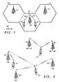
- FIG. 2is an illustration of a communication system in accordance with an embodiment of the invention.
- GSMGlobal System for Mobile communications
- UMTS TDDTime Division Duplex
- UMTS CDMACode Division Multiple Access
- DECTcan be accessed by a group of subscriber units.
- Each individual subscriber unit within the groupmay be able to access one, more or all of the available communication systems.
- a communication systemis formed comprising the group of subscriber units and the individual communication systems as communication subsystems.
- the individual communication systemsi.e. the subsystems
- the individual communication systemsare in the preferred embodiment coordinated and can share subscriber unit information through suitable network interfaces.
- the individual communication systemsare also capable of interworking such that call data can be routed from one system to the other, thereby allowing in call handover from one subsystem to the other.
- the subsystemsare completely independent and share no information or infrastructure.
- the individual communication systemsmay be operated by different operators which may operate their system completely independently and without consideration of any other communication systems, but are preferably coordinating and exchanging information with the other individual communication systems forming the sub-communication systems.
- FIG. 2shows a number of base stations of the communication system 201, 203, 205, 207, 209 in a given area. Two of the base stations 201, 203 belong to the GSM communication subsystem, one base station 205 belongs to the UMTS TDD communication subsystem, one base station 207 belongs to the UMTS CDMA communication subsystem and the last base station 209 belongs to the UMTS TDD communication subsystem.
- FIG. 2further shows a group of three subscriber units 211, 213, 215 currently within the given region. The group of subscriber units thus may potentially access four subsystems (i.e. one of the four individual communication systems). In order to determine which communication subsystem to use or access, each subscriber unit must determine information relating to each of the communication subsystems it is capable of using.
- a first subscriber unit 213if a first subscriber unit 213 is able to communicate on the UMTS TDD, UMTS CDMA and GSM communication subsystems, it must determine information relating to these three communication systems.
- the informationis typically determined by monitoring the prevailing radio conditions for the communication systems such as pilot signal levels, signal level etc or receiving information broadcast by the different communication systems and relating to characteristics of the communication system.
- the monitoringmay include any suitable information including for example available capacity or synchronisation information.
- a first subscriber unit 213monitors a subset of the communication subsystems.
- the first subscriber unit 213monitors two communication subsystems UMTS TDD and UMTS CDMA.
- This monitoringspecifically includes measuring the received pilot signal level of the base stations 205, 207 of the two communication systems UMTS TDD and UMTS CDMA.
- the monitoring by the subscriber unitsis not necessarily limited to the base stations in the given region but may well include base stations of the relevant communication systems in other regions.
- the monitoring subsetsmay be completely different or overlapping. Some subscriber units within the group may have identical monitoring subsets but at least two subscriber units out of the group of subscriber units will have different monitoring subsets.
- the monitoring information generated by the first subscriber unitis communicated to the other subscriber units 211, 215 in the group.
- the monitoring information generated by the second subscriber unit 215is communicated to the other subscriber units 211, 213.
- any monitoring information generated by other subscriber units 211is communicated to other subscriber units 213, 215.
- the monitoring information from the different subscriber units 211, 213, 215is then combined to generate combined monitoring information relating to more of the communication subsystems than those monitored by some or all of the subscriber units 211, 213, 215.
- the combination of monitoring informationcan be achieved in different ways.
- the combinationis performed in the subscriber unit.
- the second subscriber unit 215will receive monitoring information from the first subscriber unit 213 and will combine the information on the UMTS TDD and CDMA communication subsystems with the information it itself generated for the GSM and DECT communication systems. Hence, by combining this information, it will generate combined monitoring information related to all the available communication systems.
- monitoring information relating to a given characteristic of a given communication systemcan be received from a plurality of subscriber units (or can be generated locally and received from other subscriber units) and this information can be combined such that the combined information considers information received from all sources.
- the combinationmay for example be performed by averaging of the received values.
- the measured signal levels of another subscriber unit 213are considered as an indication of the pilot signal level that would be received at the second subscriber unit 215.
- the subscriber units 213, 215are located relatively close to each other, an assumption that the levels will be identical or similar is reasonable but any known method of estimating radio characteristics of a subscriber unit from that received at a different subscriber unit may be used without detracting from the current invention.
- the monitoring informationcan typically be used directly.
- the monitoring information measured by the first subscriber unit 213relates to the available capacity or tariff for a specific service on the UMTS TDD communication subsystem this information will be equally applicable to the second subscriber unit 215.
- Other examples of monitoring informationwhich is relevant for handover or access to the communication subsystems and can be used by subscriber units not having themselves determined the information include the identity of the network operator, the frequencies or codes employed, the broadcast configuration of the network, and synchronisation information.
- the monitoring of a plurality of communication subsystemsis distributed between a plurality of subscriber units and the information is shared between these. Consequently, an individual subscriber unit need only monitor a small subset of the possible communication subsystems, yet is made aware of the capabilities of all subsystems in its neighbourhood, including those it did not directly monitor itself. This significantly reduces the resource and time required by the individual subscriber unit to monitor a plurality of systems and thereby speeds up access and handovers while reducing the complexity and battery drain of the subscriber unit.
- the monitoring information generated by subscriber unitscan be distributed to other subscriber units in different ways.
- the monitoring informationis preferably communicated directly between the subscriber units without using the communication subsystems for the communication.
- a direct wireless linkis formed between the subscriber units such that the subscriber units communicate directly without any intermediate.
- the subscriber unitscommunicate a short range ad-hoc network.
- the ad-hoc networkcan be a standardised network for short range device to device communication, such as IEEE 802.11a or b currently standardised for short range ad-hoc wireless networks.
- the linkmay be formed by a wireless Local Area Network (LAN).
- the linkmay be formed by a Bluetooth link, which provides the advantage that a link is automatically and dynamically formed to subscriber units in close proximity using low cost standardised communication means.
- a linkis formed between subscriber units without using the communication subsystems for the communication, there is no additional loading of the communication subsystems.
- any suitable linkcan be used, it is not required that the communication subsystems are suitable or capable of distributing the monitoring information. This is specifically advantageous for completely separate and independent communication subsystems as there is no requirement for any coordination or exchange of monitoring information through the individual and independent communication subsystems.
- an individual communication subsystemmay be included in the communication system independently of the operators knowledge, as all that is required is that a group of subscriber units are capable of monitoring different subsets of communication systems and sharing the information.
- Specific use of ad-hoc networksprovide the advantage that suitable links between subscriber units can dynamically and automatically be formed to suit the current distribution and locations of subscriber units.
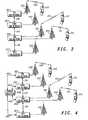
- FIG. 3illustrates a communication system where the communication subsystems are used to distribute monitoring information in accordance with a different embodiment of the invention.
- FIG. 3shows the base stations 201, 203, 205, 207, 209 and the subscriber units 211, 213, 215 of FIG. 2 .
- FIG 3shows the UMTS TDD base station 205 connected to a UMTS TDD fixed sub-network 301, the UMTS CDMA base station 207 connected to a UMTS CDMA fixed sub-network 303, the GSM base stations 201, 203 connected to a GSM fixed sub-network 305 and the DECT base station 209 connected to a DECT fixed sub-network 307.
- the fixed network of the communication systemis thus made up by the combination of the fixed sub-networks of the individual communication systems i.e. the communication subsystems.
- the first subscriber unit 213determines monitoring information as previously described. The determined monitoring information is subsequently communicated to the base station serving the subscriber unit 213.
- the subscriber unitis currently in the TDD mode and is served by the TDD base station 205 over a TDD communication link 309.
- the subscriber unit 213communicates the monitoring information to the UMTS TDD base station 205 through this TDD link 309.
- the base station 205communicates the received monitoring information to the UMTS TDD fixed sub-network 301.
- other subscriber unitscommunicate monitoring information determined by them to the fixed network through a suitable link, which is preferably a serving link.
- the second subscriber unit 215communicates the monitoring information to the GSM fixed sub-network 305 through the serving GSM base station 203 using the serving link 311, and the third subscriber unit 211 communicates the monitoring information to the GSM fixed sub-network 305 through the serving GSM base station 201 using the serving link 313.
- the fixed sub-networks 301, 303, 305, 307are interconnected by communication links 315, 317, 319 and the received monitoring information is communicated between all the fixed sub-networks 301, 303. 305, 307 such that each of the fixed sub-networks 301, 303, 305, 307 have all the monitoring information generated by any of the subscriber units 211, 213, 215.
- the total informationis then broadcast on all the communication subsystems so that all subscriber units in the group receive all the monitoring information determined.
- the subscriber unitscan upon receiving the total monitoring information process combine the information as required.
- the informationmay be broadcast unmodified and the subscriber unit may combine it, e.g. by averaging of the values.
- the combining of the first and second monitoring informationis performed partly in the fixed network and partly in the subscriber unit.
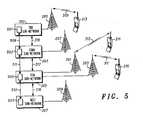
- FIG. 4illustrates a communication system with central combination of monitoring information in accordance with an embodiment of the invention.
- all fixed sub-networks 301, 303, 305, 307are connected by communication links 401, 403, 405, 407 to a central processor 409 for combining the monitoring information.
- the central processor 409for combining the monitoring information.
- the central processor 409receives the monitoring information from all subscriber units 211, 213, 215 and combines the information into a single monitoring information set.
- the single combined monitoring information setcomprises information from all subscriber units and relates to all communication subsystems.
- the single monitoring information setmay only comprise monitoring information from a subset of subscriber units or relate to a subset of the communication subsystems, for example dependent on the current capability of the subscriber units included in the monitoring group.
- the monitoring information setis communicated to all of the communication subsystems, which broadcast the information. Consequently, each of the subscriber units 211, 213, 215 can receive the combined information relating to all communication subsystems simply by receiving the broadcast channel of the preferred communication subsystem. Further, there is no requirement for the individual subscriber units 211, 213, 215 to process any information, as this has already been done centrally by the central processor 409.
- FIG. 5illustrates a communication system with distributed combination of monitoring information in accordance with an embodiment of the invention.
- all fixed sub-networks 301, 303, 305, 307comprise a combining processor 501, 503, 505, 507 and the combining processors are directly interconnected by communication links 509, 511, 513.
- Each of the combining processors 501,503, 505, 507is capable of receiving monitoring information from and transmitting monitoring information to other combining processors 501, 503, 505, 507.
- a combining processor 501, 503, 505, 507will store the monitoring information reported from subscriber units to the communication subsystem of the combining processor 501, 503, 505, 507 and communicate it to other combining processors 501, 503, 505, 507.
- each combining processor 501, 503, 505, 507will thus accumulate all the monitoring information reported on any of the communication subsystems. It will further combine the monitoring information to generate a combined monitoring information set, which it will broadcast on the associated communication subsystem.
- the monitoring informationcomprises information related to the location of the subscriber unit when the monitoring information was generated.
- the monitoring information subsets communicated by subscriber unitsare transmitted together with information relating to the location of the originating subscriber unit when it monitored the communication systems.
- Individual location information for each individual piece of monitoring informationmay be used or a single location tag for the entire communicated monitoring information subset can be used.
- a subscriber unit receiving a monitoring information subsetcan in this embodiment determine how close it is to the location where the monitoring information was generated and therefrom determine how relevant the information is to the subscriber unit.
- a receiving subscriber unitmay only use monitoring information that was generated within a certain distance of the current location of the subscriber unit.
- the location informationcan be used to discard or accept received monitoring information dynamically as the subscriber unit moves. Any known method of determining location of a subscriber unit can be used without detracting from the invention.
- the monitoring informationcomprises information related to the time of generation of the monitoring information.
- the monitoring information subsets communicated by subscriber unitsare transmitted together with information relating to the time at which the originating subscriber unit monitored the communication systems.
- Individual time information for each individual piece of monitoring informationmay be used or a single time tag for the entire communicated monitoring information subset can be used.
- a subscriber unit receiving a monitoring information subsetcan in this embodiment determine how much time has elapsed since the monitoring was performed and thus how relevant it is to the subscriber unit.
- the time informationis in the form of an expiry time which is added to the monitoring information subset and indicates a time instant up to which the information may be considered valid.
- the components and functionality describedmay be implemented in any suitable manner to provide suitable apparatus.
- the componentsmay consist of a single discrete entity, or may alternatively be formed by adapting existing parts or components.
- the required adaptationmay be implemented in the form of processor-implementable instructions stored on a storage medium, such as a floppy disk, hard disk, PROM, RAM or any combination of these or other storage media
- the functionalitymay be implemented in the form of hardware, firmware, software, or any combination of these.
- the subscriber units operable to monitor and/ or access a plurality of communication systemsmay be implemented in any suitable form whether by use of software definable radios, fully parallel subscriber units having independent circuitry for each individual communication system.
Landscapes
- Engineering & Computer Science (AREA)
- Computer Security & Cryptography (AREA)
- Computer Networks & Wireless Communication (AREA)
- Signal Processing (AREA)
- Mobile Radio Communication Systems (AREA)
- Alarm Systems (AREA)
- Radar Systems Or Details Thereof (AREA)
- Monitoring And Testing Of Transmission In General (AREA)
Abstract
Description
- This invention relates to a wireless communication system, a wireless communication device and method of monitoring therefor and in particular to cellular communication system and method of monitoring different communication subsystems.
- In a cellular communication system, each of the subscriber units (typically mobile stations, communication terminals, wireless devices, user equipment, remote terminals etc) communicates with a fixed base station. Communication from the subscriber unit to the base station is known as uplink, and communication from the base station to the subscriber unit is known as downlink. The total coverage area of the system is divided into a number of separate areas or cells, each predominantly covered by a single base station. The cells are typically geographically distinct with an overlapping coverage area with neighbouring cells.
FIG. 1 illustrates acellular communication system 100. In the system, abase station 101 communicates with a number ofsubscriber units 103 overradio channels 105. In the cellular system, thebase station 101 covers users within a certaingeographical area 107, whereas othergeographical areas other base stations - As a subscriber unit moves from the coverage area of one cell to the coverage area of another cell, the communication link will change from being between the subscriber unit and the base station of the first cell, to being between the subscriber unit and the base station of the second cell. This is known as a handover. Specifically, some cells may lie completely within the coverage of other larger cells.
- All base stations are interconnected by a fixed network. This fixed network comprises communication lines, switches, interfaces to other communication networks and various controllers required for operating the network. A call from a subscriber unit is routed through the fixed network to the destination specific for this call. If the call is between two subscriber units of the same communication system, the call will be routed through the fixed network to the base station of the cell in which the other subscriber unit currently is. A connection is thus established between the two serving cells through the fixed network. Alternatively, if the call is between a subscriber unit and a telephone connected to the Public Switched Telephone Network (PSTN) the call is routed from the serving base station to the interface between the cellular mobile communication system and the PSTN. It is then routed from the interface to the telephone by the PSTN. A similar procedure is used for other public or private networks.
- A cellular mobile communication system is allocated a frequency spectrum for the radio communication between the subscriber units and the base stations. This spectrum must be shared between all subscriber units simultaneously using the system.
- One method of sharing this spectrum is by a technique known as Time Division Multiple Access (TDMA). In a TDMA communication system, the frequency spectrum is typically divided into a number of separate frequency channels or carriers and for each of these carriers a plurality of subscriber units are served by being allocated distinct time intervals. Thus in the example of the TDMA communication system GSM, the frequency spectrum is divided into 200 kHz frequency channels each of which is divided into eight separate time slots. A subscriber unit is allocated a specific time slot on a given frequency channel for communication with the serving base station. Further details of GSM can be found in' The GSM System for Mobile Communications', Bay Foreign Language Books, authors Michel Mouly and Marie-Bernadette Pautet, 1992, ISBN 2950719007.
- Another method of sharing cellular spectrum is by a technique known as Code Division Multiple Access (CDMA). In a Direct Sequence CDMA (DS-CDMA) communication system, the signals are multiplied by a high rate code whereby the signal is spread over a larger frequency spectrum. A narrowband signal is thus spread and transmitted as a wideband signal. At the receiver, the original narrowband signal is regenerated by multiplication of the received signal with the same code used to spread the signal in the transmitter. A signal which has been spread by use of a different code will not be despread by the receiver but will remain a wide band signal. It will then be removed by filtering after the de-spreading operation. In the receiver, the majority of interference from signals in the same frequency spectrum as the wanted signal can thus be removed by filtering. Consequently, a plurality of subscriber units can be accommodated in the same wideband spectrum by allocating different codes for different subscriber units. Codes are chosen to minimise the interference caused between subscriber units typically by choosing orthogonal codes when possible. A further description of CDMA communication systems can be found in'Spread Spectrum CDMA Systems for Wireless Communications', Glisic & Vucetic, Artech house Publishers, 1997, ISBN 0-89006-858-5. Examples of CDMA cellular communication systems are IS 95 and the Universal Mobile Telecommunication System (UMTS).
- Currently an increasing number of wireless communication systems accessible by a remote terminal or subscriber unit are becoming available. The service, cost and accessibility of these communication systems vary and in order for a subscriber unit to use the most suitable communication system in a given situation, subscriber units are developed which can operate on a variety of communication systems. As such, current GSM mobiles are developed which can potentially use different communication systems such as GSM 900, GSM 1800, GSM 1900 and DECT. A subscriber unit equipped to use all of these communication systems will ideally monitor all these subsystems and select the communication system best suited for the current requirements of the subscriber unit in the current conditions.
- Even more complex subscriber units are planned that will be capable of using an even wider variety and number of communication systems. Thus it is envisaged that software definable radios will soon be available which are capable of using all or the majority of the following communication systems:
- GSM 900
- GSM 1800
- GSM 1900
- UMTS 1800
- UMTS FDD
- UMTSTDD
- UMTS TD-SCDMA
- IS95
- CDMA2000
- TDMA
- BRAN
- WLL
- Bluetooth
- DECT
- Fixed access (PSTN, LAN)
- IEEE802.11a
- IEEE802.11b
- To a subscriber unit capable of using a plurality of communication systems, the individual wireless communication systems thus become subsystems in a larger overlaying communication system comprised by the aggregation of communication systems available to a subscriber unit.
- However, in order for the subscriber unit to determine which subsystem is the optimal communication system, it is required that it scans and monitors a plurality of the subsystems. Even for the relevant and simple GSM subscriber unit currently on the market this is a complex and time and resource-demanding task. The complexity of this task is increased as the different mixes of what systems and services are available to the users may vary significantly between different regions.
- As example of associated technology
GB-A-2 294 844 EP-A-1 202 593 describes obtaining monitoring information from a terminal,US-A-5 613 204 describes a roaming subscriber unit that identifies available service providers in its area, andWO 98/27766 A - The problem is significantly exacerbated when a multitude of very different communication subsystems having very different radio access technologies are used. Monitoring and scanning different subsystems will involve significant re-configuration of the radio subsystem of the subscriber unit (assuming a single radio subsystem, not parallel radios which would significantly increase complexity and cost), and synchronisation with the new network technologies flame and broadcast schedules. This complexity will make scanning slow and could interfere with currently active communications from that terminal. The slowness of scanning could also delay handover of calls between network types and result in dropped calls. In addition, the monitoring would require complex algorithms and therefore increase the resource requirement and reduce battery life of the subscriber unit.
- Hence, the current schemes for monitoring different communication systems are complex, slow and very resource demanding and there is thus a need for an improved system monitoring communication systems by a subscriber unit.
- The inventors of the current invention have realised that conventional approaches for monitoring communication systems are suboptimal and can be improved. The invention seeks to provide an improvement in the monitoring of a plurality of communication systems and specifically it seeks to improve the time, resource and complexity required for monitoring of a plurality of communication systems.
- Accordingly there is provided a wireless communication system in accordance with claim 1, a wireless communication system in accordance with claim 12, and a method of monitoring in a wireless communication system in accordance with claim 16.
- An embodiment of the present invention is described below, by way of example only, with reference to the Drawings, in which:
FIG. 1 is an illustration of a cellular communication system according to prior art;FIG. 2 is an illustration of a communication system in accordance with an embodiment of the invention;FIG. 3 illustrates a communication system where the communication subsystems are used to distribute monitoring information in accordance with a different embodiment of the invention;FIG. 4 illustrates a communication system with central combination of monitoring information in accordance with an embodiment of the invention; andFIG. 5 illustrates a communication system with distributed combination of monitoring information in accordance with an embodiment of the invention.FIG. 2 is an illustration of a communication system in accordance with an embodiment of the invention.- In the described embodiment, well-known individual communication systems GSM, UMTS TDD (Time Division Duplex), UMTS CDMA (Code Division Multiple Access) and DECT can be accessed by a group of subscriber units. Each individual subscriber unit within the group may be able to access one, more or all of the available communication systems. Thus a communication system is formed comprising the group of subscriber units and the individual communication systems as communication subsystems. The individual communication systems (i.e. the subsystems) are in the preferred embodiment coordinated and can share subscriber unit information through suitable network interfaces. In the preferred embodiment, the individual communication systems are also capable of interworking such that call data can be routed from one system to the other, thereby allowing in call handover from one subsystem to the other. However, in other communication systems the subsystems are completely independent and share no information or infrastructure. In this case, it is the capability of the group of mobiles as a whole which define which individual communication systems are subsystems of the communication system. Hence, the individual communication systems may be operated by different operators which may operate their system completely independently and without consideration of any other communication systems, but are preferably coordinating and exchanging information with the other individual communication systems forming the sub-communication systems.
FIG. 2 shows a number of base stations of thecommunication system base stations base station 205 belongs to the UMTS TDD communication subsystem, onebase station 207 belongs to the UMTS CDMA communication subsystem and thelast base station 209 belongs to the UMTS TDD communication subsystem.FIG. 2 further shows a group of threesubscriber units - Hence, if a
first subscriber unit 213 is able to communicate on the UMTS TDD, UMTS CDMA and GSM communication subsystems, it must determine information relating to these three communication systems. The information is typically determined by monitoring the prevailing radio conditions for the communication systems such as pilot signal levels, signal level etc or receiving information broadcast by the different communication systems and relating to characteristics of the communication system. However, the monitoring may include any suitable information including for example available capacity or synchronisation information. - In accordance with the described embodiment, a
first subscriber unit 213 monitors a subset of the communication subsystems. In the example ofFIG 2 , thefirst subscriber unit 213 monitors two communication subsystems UMTS TDD and UMTS CDMA. This monitoring specifically includes measuring the received pilot signal level of thebase stations - Further in accordance with the described embodiment, a
second subscriber unit 215, capable of communicating on all of the four communication subsystems, monitors a second subset of the communication subsystems comprising the GSM communication subsystem and the DECT communication subsystem. Specifically, thesecond subscriber unit 215 measures the received pilot signal level from theGSM base stations DECT base station 209. The monitoring subsets may be completely different or overlapping. Some subscriber units within the group may have identical monitoring subsets but at least two subscriber units out of the group of subscriber units will have different monitoring subsets. - In accordance with an embodiment of the invention, the monitoring information generated by the first subscriber unit is communicated to the
other subscriber units second subscriber unit 215 is communicated to theother subscriber units other subscriber units 211 is communicated toother subscriber units different subscriber units subscriber units - The combination of monitoring information can be achieved in different ways. In the preferred embodiment, the combination is performed in the subscriber unit. Thus the
second subscriber unit 215 will receive monitoring information from thefirst subscriber unit 213 and will combine the information on the UMTS TDD and CDMA communication subsystems with the information it itself generated for the GSM and DECT communication systems. Hence, by combining this information, it will generate combined monitoring information related to all the available communication systems. Furthermore, monitoring information relating to a given characteristic of a given communication system can be received from a plurality of subscriber units (or can be generated locally and received from other subscriber units) and this information can be combined such that the combined information considers information received from all sources. The combination may for example be performed by averaging of the received values. - In the example of the monitoring information being pilot signal levels, the measured signal levels of another
subscriber unit 213 are considered as an indication of the pilot signal level that would be received at thesecond subscriber unit 215. As thesubscriber units - If the monitoring information relates to characteristics of the communication subsystem that are independent of the radio characteristics from a base station to a subscriber unit, the monitoring information can typically be used directly. For example, if the monitoring information measured by the
first subscriber unit 213 relates to the available capacity or tariff for a specific service on the UMTS TDD communication subsystem this information will be equally applicable to thesecond subscriber unit 215. Other examples of monitoring information which is relevant for handover or access to the communication subsystems and can be used by subscriber units not having themselves determined the information include the identity of the network operator, the frequencies or codes employed, the broadcast configuration of the network, and synchronisation information. - Thus in accordance with the embodiment of the invention, the monitoring of a plurality of communication subsystems is distributed between a plurality of subscriber units and the information is shared between these. Consequently, an individual subscriber unit need only monitor a small subset of the possible communication subsystems, yet is made aware of the capabilities of all subsystems in its neighbourhood, including those it did not directly monitor itself. This significantly reduces the resource and time required by the individual subscriber unit to monitor a plurality of systems and thereby speeds up access and handovers while reducing the complexity and battery drain of the subscriber unit.
- The monitoring information generated by subscriber units can be distributed to other subscriber units in different ways. In the preferred embodiment, where the combining of monitoring information is performed in the subscriber unit, the monitoring information is preferably communicated directly between the subscriber units without using the communication subsystems for the communication. In one embodiment a direct wireless link is formed between the subscriber units such that the subscriber units communicate directly without any intermediate. In another embodiment the subscriber units communicate a short range ad-hoc network. Specifically, the ad-hoc network can be a standardised network for short range device to device communication, such as IEEE 802.11a or b currently standardised for short range ad-hoc wireless networks. In other embodiments the link may be formed by a wireless Local Area Network (LAN). In yet another embodiment the link may be formed by a Bluetooth link, which provides the advantage that a link is automatically and dynamically formed to subscriber units in close proximity using low cost standardised communication means.
- In the specific embodiments wherein a link is formed between subscriber units without using the communication subsystems for the communication, there is no additional loading of the communication subsystems. Furthermore, as any suitable link can be used, it is not required that the communication subsystems are suitable or capable of distributing the monitoring information. This is specifically advantageous for completely separate and independent communication subsystems as there is no requirement for any coordination or exchange of monitoring information through the individual and independent communication subsystems. Thus an individual communication subsystem may be included in the communication system independently of the operators knowledge, as all that is required is that a group of subscriber units are capable of monitoring different subsets of communication systems and sharing the information. Specific use of ad-hoc networks provide the advantage that suitable links between subscriber units can dynamically and automatically be formed to suit the current distribution and locations of subscriber units.
FIG. 3 illustrates a communication system where the communication subsystems are used to distribute monitoring information in accordance with a different embodiment of the invention.FIG. 3 shows thebase stations subscriber units FIG. 2 . In additionFIG 3 shows the UMTSTDD base station 205 connected to a UMTS TDD fixedsub-network 301, the UMTSCDMA base station 207 connected to a UMTS CDMA fixedsub-network 303, theGSM base stations sub-network 305 and theDECT base station 209 connected to a DECT fixedsub-network 307. The fixed network of the communication system is thus made up by the combination of the fixed sub-networks of the individual communication systems i.e. the communication subsystems.- The
first subscriber unit 213 determines monitoring information as previously described. The determined monitoring information is subsequently communicated to the base station serving thesubscriber unit 213. In the example ofFIG. 3 , the subscriber unit is currently in the TDD mode and is served by theTDD base station 205 over aTDD communication link 309. Thesubscriber unit 213 communicates the monitoring information to the UMTSTDD base station 205 through thisTDD link 309. Thebase station 205 communicates the received monitoring information to the UMTS TDD fixedsub-network 301. Likewise other subscriber units communicate monitoring information determined by them to the fixed network through a suitable link, which is preferably a serving link. Thus, thesecond subscriber unit 215 communicates the monitoring information to the GSM fixedsub-network 305 through the servingGSM base station 203 using the servinglink 311, and thethird subscriber unit 211 communicates the monitoring information to the GSM fixedsub-network 305 through the servingGSM base station 201 using the servinglink 313. - The fixed
sub-networks communication links sub-networks sub-networks subscriber units FIG. 4 illustrates a communication system with central combination of monitoring information in accordance with an embodiment of the invention. In this embodiment, all fixedsub-networks communication links central processor 409 for combining the monitoring information. Thus thecentral processor 409 for combining the monitoring information. Thus thecentral processor 409 receives the monitoring information from allsubscriber units subscriber units individual subscriber units central processor 409.FIG. 5 illustrates a communication system with distributed combination of monitoring information in accordance with an embodiment of the invention. In this embodiment all fixedsub-networks processor communication links processors processor processor processors subscriber units respective combining processor processor - In accordance with one embodiment of the invention, the monitoring information comprises information related to the location of the subscriber unit when the monitoring information was generated. Thus the monitoring information subsets communicated by subscriber units are transmitted together with information relating to the location of the originating subscriber unit when it monitored the communication systems. Individual location information for each individual piece of monitoring information may be used or a single location tag for the entire communicated monitoring information subset can be used. A subscriber unit receiving a monitoring information subset can in this embodiment determine how close it is to the location where the monitoring information was generated and therefrom determine how relevant the information is to the subscriber unit. Thus a receiving subscriber unit may only use monitoring information that was generated within a certain distance of the current location of the subscriber unit. Further the location information can be used to discard or accept received monitoring information dynamically as the subscriber unit moves. Any known method of determining location of a subscriber unit can be used without detracting from the invention.
- In accordance with one embodiment of the invention, the monitoring information comprises information related to the time of generation of the monitoring information. Thus the monitoring information subsets communicated by subscriber units are transmitted together with information relating to the time at which the originating subscriber unit monitored the communication systems. Individual time information for each individual piece of monitoring information may be used or a single time tag for the entire communicated monitoring information subset can be used. A subscriber unit receiving a monitoring information subset can in this embodiment determine how much time has elapsed since the monitoring was performed and thus how relevant it is to the subscriber unit. In one embodiment, the time information is in the form of an expiry time which is added to the monitoring information subset and indicates a time instant up to which the information may be considered valid.
- The components and functionality described may be implemented in any suitable manner to provide suitable apparatus. Specifically, the components may consist of a single discrete entity, or may alternatively be formed by adapting existing parts or components. As such the required adaptation may be implemented in the form of processor-implementable instructions stored on a storage medium, such as a floppy disk, hard disk, PROM, RAM or any combination of these or other storage media Furthermore, the functionality may be implemented in the form of hardware, firmware, software, or any combination of these. Specifically, the subscriber units operable to monitor and/ or access a plurality of communication systems may be implemented in any suitable form whether by use of software definable radios, fully parallel subscriber units having independent circuitry for each individual communication system.
- It will be understood that the invention tends to provide the following advantages singly or in any combination:
- it provides for low complexity subscriber units operable on a plurality of individual communication systems.
- it significantly reduces time required by the individual subscriber unit to monitor a plurality of systems and thereby speeds up access and handovers.
Claims (21)
- A wireless communication system (100) having a plurality of communication subsystems serving a plurality of subscriber unitscharacterized by comprising
a first subscriber unit (213) arranged to monitor a first subset of the plurality of communication subsystems thereby generating a first monitoring information subset relevant to the first subset of communication systems;
a second subscriber unit (215) arranged to monitor a second subset of the plurality of communication subsystems different from the first subset of communication subsystems thereby generating a second monitoring information subset relevant to the second subset of communication systems; and
means (301, 303, 305, 307, 211, 213, 215, 409, 501, 503, 505, 507) for combining the first and second monitoring information subsets into a combined monitoring information set relevant to communication subsystems of both the first and second subset of communication subsystems including means arranged to obtain the first and second monitoring information subset and means arranged to communicate the combined monitoring information set, and
wherein the first and second subscriber units include means for communicating with the communication subsystems of its own subset and at least one communication subsystem of the other subset, means for communicating its generated monitoring information subset, and means for obtaining the combined monitoring information set. - A wireless communication system as claimed in claim 1 wherein the means for combining is in the second subscriber unit (215) and the communication system comprises means (301, 303, 305, 307) for communicating the first monitoring information subset from the first subscriber unit (213) to the second subscriber unit (215).
- A wireless communication system as claimed in claim 2 wherein the means for communicating the first monitoring information subset includes a direct wireless link from the first (213) to the second subscriber unit (215).
- A wireless communication system as claimed in claim 2 wherein the means for communicating the first monitoring information subset comprises a short range ad hoc network.
- A wireless communication system as claimed in claim 2 wherein the means for communicating the first monitoring information subset comprises a wireless Bluetooth connection.
- A wireless communication system as claimed in claim 1 wherein means for combining (301, 303, 305, 307) is in a fixed network of the communication system and the communication system comprises means (205, 309) for communicating the first monitoring information subset from the first subscriber unit (213) to fixed network (301) and means (311, 203) for communicating the second monitoring information subset from the second subscriber unit (215) to fixed network (305) and means for communication (301 205) the combined monitoring information set to the first subscriber unit.
- A wireless communication system as claimed in claim 6 further comprising means for broadcasting the combined monitoring information subset to a plurality of subscriber units (211, 213, 215).
- A wireless communication system as claimed in claim 7 means for broadcasting are arranged to broadcast the combined monitoring information subset on a broadcast plurality of communication subsystems.
- A wireless communication system as claimed in any previous claim wherein the first and second monitoring information comprises information related to the location of the associated first and second subscriber unit (213, 215) when the monitoring information was generated.
- A wireless communication system as claimed in claim 1 wherein the first and second monitoring information comprises information related to the time of generation of the monitoring information.
- A wireless communication system as claimed in claim 1 wherein each communication subsystem comprises a fixed sub-network (301, 303, 305, 307) and wherein a plurality of means for combining is distributed between the fixed sub-networks (301, 303, 305, 307).
- A wireless communication device for a communication system having a plurality of communication subsystems serving a plurality of subscriber units (211, 213, 215)characterized by comprising:a first subscriber unit (213) arranged to monitor a first subset (301) of the plurality of communication subsystems thereby generating a first monitoring information subset relevant to the first subset of communication systems, and comprising means for communicating with the first subset of the plurality of communication subsystems and at least one communication subsystem of a second subset of the plurality of communication subsystemsmeans for receiving (203) a second monitoring information subset relevant to the second subset (305) of communication systems generated by a second subscriber unit (215) arranged to monitor the second subset (305) of the plurality of communication subsystems which is different from the first subset (301) of communication subsystems; andmeans for combining (301, 303, 305, 307, 211, 213, 215, 409, 501, 503, 505, 507) the first and second monitoring information subsets into a combined monitoring information set relevant to communication subsystems of both the first and second subset of communication subsystems; andmeans for communicating the combined monitoring information set to other subscriber units (211, 215).
- A wireless communication device as claimed in claim 12 wherein the means for receiving (203) the second monitoring information subset are operable to receive the second monitoring information subset from a direct wireless link from the second (215) to the first subscriber unit (213).
- A wireless communication device as claimed in claim 12 wherein the means for receiving (203) the second monitoring information subset are operable to receive the second monitoring information subset from a short range ad hoc network.
- A wireless communication device as claimed in claim 12 wherein the means for receiving (203) the second monitoring information subset are operable to receive the second monitoring information subset from a Bluetooth connection.
- A method of monitoring in a wireless communication system having a plurality of communication subsystems serving a plurality of subscriber units, the methodcharacterized by comprising the steps of:monitoring, in a first subscriber unit, a first subset of the plurality of communication subsystems through communicating with the communication subsystems of the first subset and at least one a second subset of the communication subsystems thereby generating a first monitoring information subset relevant to the first subset of communication systems;monitoring, in a second subscriber unit, the second subset of the plurality of communication subsystems which is different from the first subset of communication subsystems through communicating with the communication subsystems of the second subset and at least one communication subsystem of the first subset of the communication subsystems thereby generating a second monitoring information subset relevant to the second subset of communication systems;communicating the generated first and second monitoring information subset;obtaining the first and second monitoring information subset;combining the first and second monitoring information subsets into a combined monitoring information set relevant to communication subsystems of both the first and second subset of communication subsystems;communicating the combined monitoring information set; andobtaining the combined monitoring information set.
- A method of monitoring as claimed in claim 16 wherein the step of combining occurs in the second subscriber unit and the first monitoring information subset is communicated from the first subscriber unit to the second communication unit through a direct wireless link from the first to the second subscriber unit.
- A method of monitoring as claimed in claim 16 wherein the step of combining occurs in the second subscriber unit and the first monitoring information subset is communicated from the first subscriber unit to the second communication unit through a short range ad hoc network.
- A method of monitoring as claimed in claim 16 wherein the step of combining occurs in the second subscriber unit and the first monitoring information subset is communicated from the first subscriber unit to the second communication unit through a wireless Bluetooth connection.
- A method of monitoring as claimed in claim 16 wherein the step of combining the first and second monitoring information subset into a combined monitoring information set comprises the steps of:communicating the first monitoring information subset from the first subscriber unit to fixed network;communicating the second monitoring information subset from the second subscriber unit to fixed network;combining the combining the first and second monitoring information subset into a combined monitoring information set in the fixed network; andcommunicating the combined monitoring information set to the first subscriber unit.
- A method of monitoring as claimed in claim 20 wherein the step of communicating the combined monitoring information set comprises the step of broadcasting the combined monitoring information subset to a plurality of subscriber units.
Applications Claiming Priority (3)
| Application Number | Priority Date | Filing Date | Title |
|---|---|---|---|
| GB0210283AGB2388276B (en) | 2002-05-04 | 2002-05-04 | A wireless communicaton system, a wireless communication device and method of monitoring therefor |
| GB0210283 | 2002-05-04 | ||
| PCT/EP2003/004189WO2003094559A2 (en) | 2002-05-04 | 2003-04-18 | A wireless communication system a wireless communication device and method of monitoring therefor |
Publications (2)
| Publication Number | Publication Date |
|---|---|
| EP1504626A2 EP1504626A2 (en) | 2005-02-09 |
| EP1504626B1true EP1504626B1 (en) | 2010-07-14 |
Family
ID=9936099
Family Applications (1)
| Application Number | Title | Priority Date | Filing Date |
|---|---|---|---|
| EP03727339AExpired - LifetimeEP1504626B1 (en) | 2002-05-04 | 2003-04-18 | A wireless communication system a wireless communication device and method of monitoring therefor |
Country Status (9)
| Country | Link |
|---|---|
| EP (1) | EP1504626B1 (en) |
| JP (1) | JP4143065B2 (en) |
| KR (1) | KR100994917B1 (en) |
| CN (1) | CN100364358C (en) |
| AT (1) | ATE474430T1 (en) |
| AU (1) | AU2003233044A1 (en) |
| DE (1) | DE60333358D1 (en) |
| GB (1) | GB2388276B (en) |
| WO (1) | WO2003094559A2 (en) |
Families Citing this family (9)
| Publication number | Priority date | Publication date | Assignee | Title |
|---|---|---|---|---|
| WO2007016940A1 (en)* | 2005-08-05 | 2007-02-15 | Telefonaktiebolaget Lm Ericsson (Publ) | Communication system |
| ATE444668T1 (en)* | 2006-07-28 | 2009-10-15 | Research In Motion Ltd | APPARATUS AND ASSOCIATED METHOD FOR FACILITATING RADIO SUBSYSTEM SELECTION IN A PACKET DATA COMMUNICATIONS SYSTEM |
| US7796605B2 (en) | 2006-07-28 | 2010-09-14 | Research In Motion Limited | Apparatus, and associated method, for facilitating radio sub-system selection in a packet radio communication system |
| US20090047964A1 (en) | 2007-08-17 | 2009-02-19 | Qualcomm Incorporated | Handoff in ad-hoc mobile broadband networks |
| US8644206B2 (en)* | 2007-08-17 | 2014-02-04 | Qualcomm Incorporated | Ad hoc service provider configuration for broadcasting service information |
| EP2031925B1 (en)* | 2007-08-17 | 2016-08-17 | Qualcomm Incorporated | Ad hoc service provider configuration for broadcasting service information |
| KR101642309B1 (en)* | 2008-11-06 | 2016-07-25 | 엘지전자 주식회사 | A method for monitoring a downlink control channel |
| WO2010095913A2 (en)* | 2009-02-23 | 2010-08-26 | 엘지전자주식회사 | Control channel monitoring apparatus in multi-carrier system and method thereof |
| US9179367B2 (en) | 2009-05-26 | 2015-11-03 | Qualcomm Incorporated | Maximizing service provider utility in a heterogeneous wireless ad-hoc network |
Family Cites Families (9)
| Publication number | Priority date | Publication date | Assignee | Title |
|---|---|---|---|---|
| GB2282730B (en)* | 1993-10-08 | 1998-01-28 | Nokia Telecommunications Oy | Dual mode subscriber terminal and a handover procedure of the dual mode subscriber terminal in a mobile telecommunication network |
| GB2294844B (en)* | 1994-11-07 | 1999-05-26 | Motorola Inc | Communications operating system and method therefor |
| US5613204A (en)* | 1994-12-22 | 1997-03-18 | Bell Atlantic Mobile Systems, Inc. | Beacon system for roaming cellular stations |
| WO1998027766A2 (en)* | 1996-12-19 | 1998-06-25 | Siemens Aktiengesellschaft | Method and device for reducing electricity consumption in mobile multimode telecommunication terminals |
| WO2000004729A2 (en)* | 1998-07-20 | 2000-01-27 | Qualcomm Incorporated | Base station handover in a hybrid gsm/cdma network |
| US20020082019A1 (en)* | 1998-12-30 | 2002-06-27 | Oguz Sunay | Methods and apparatus for accomplishing inter-frequency, inter-network, and inter-tier soft handoff using dual transmission/reception or compression |
| US6393286B1 (en)* | 1999-11-17 | 2002-05-21 | Telefonaktiebolaget Lm Ericsson (Publ) | Method for improving handovers between mobile communication systems |
| JP3389908B2 (en)* | 2000-01-07 | 2003-03-24 | 日本電気株式会社 | Mobile terminal network selection method and storage medium storing mobile terminal network selection program |
| JP3732389B2 (en)* | 2000-06-16 | 2006-01-05 | 松下電器産業株式会社 | Wireless communication system, base station device, communication terminal device, and wireless communication method |
- 2002
- 2002-05-04GBGB0210283Apatent/GB2388276B/ennot_activeExpired - Fee Related
- 2003
- 2003-04-18CNCNB038101262Apatent/CN100364358C/ennot_activeExpired - Lifetime
- 2003-04-18KRKR1020047017764Apatent/KR100994917B1/ennot_activeExpired - Fee Related
- 2003-04-18EPEP03727339Apatent/EP1504626B1/ennot_activeExpired - Lifetime
- 2003-04-18AUAU2003233044Apatent/AU2003233044A1/ennot_activeAbandoned
- 2003-04-18WOPCT/EP2003/004189patent/WO2003094559A2/enactiveApplication Filing
- 2003-04-18JPJP2004502664Apatent/JP4143065B2/ennot_activeExpired - Lifetime
- 2003-04-18ATAT03727339Tpatent/ATE474430T1/ennot_activeIP Right Cessation
- 2003-04-18DEDE60333358Tpatent/DE60333358D1/ennot_activeExpired - Lifetime
Also Published As
| Publication number | Publication date |
|---|---|
| GB2388276A (en) | 2003-11-05 |
| KR100994917B1 (en) | 2010-11-19 |
| ATE474430T1 (en) | 2010-07-15 |
| JP4143065B2 (en) | 2008-09-03 |
| AU2003233044A1 (en) | 2003-11-17 |
| GB2388276B (en) | 2004-06-30 |
| JP2005525029A (en) | 2005-08-18 |
| KR20040106467A (en) | 2004-12-17 |
| DE60333358D1 (en) | 2010-08-26 |
| CN100364358C (en) | 2008-01-23 |
| EP1504626A2 (en) | 2005-02-09 |
| WO2003094559A2 (en) | 2003-11-13 |
| CN1650667A (en) | 2005-08-03 |
| GB0210283D0 (en) | 2002-06-12 |
| WO2003094559A3 (en) | 2004-02-05 |
Similar Documents
| Publication | Publication Date | Title |
|---|---|---|
| CN100581299C (en) | Method and apparatus for selecting carriers | |
| US6788656B1 (en) | Communication system | |
| JP3215018B2 (en) | Mobile communication system | |
| US5515509A (en) | Method and apparatus for implementing self-organization in a wireless local area network | |
| US8180354B2 (en) | Method for allocating radio resource in multi-carrier time division duplex mobile communication system | |
| EP0421964B1 (en) | A method of communication in mobile radio systems | |
| US6590878B1 (en) | Mobile communication system with shared time slots and frequency channels | |
| US7515568B2 (en) | Neighborhood wireless protocol with switchable ad hoc and wide area network coverage | |
| KR101171713B1 (en) | Configurable downlink and uplink channels in a wireless communication system | |
| US20050037766A1 (en) | Method of assigning transmission channels in a telecommunications network and user station | |
| EP1459461B1 (en) | Utra tdd time slots allocation | |
| US6684079B1 (en) | Method for disturbance-free operation of at least two base stations in a universal mobile telecommunications system | |
| JP2001339770A (en) | Wireless communication system and communication terminal device used therefor | |
| EP1504626B1 (en) | A wireless communication system a wireless communication device and method of monitoring therefor | |
| JP3315869B2 (en) | Cell selection method in CDMA mobile communication system | |
| RU2454043C2 (en) | Method for data transmission via cellular communication system and system for its implementation | |
| CA2261309C (en) | Base stations control system in mobile communication system | |
| Silventoinen et al. | Radio resource management in a novel indoor GSM base station system | |
| HK1153867A1 (en) | Method, base station and mobile station for tdd operation in a communication system |
Legal Events
| Date | Code | Title | Description |
|---|---|---|---|
| PUAI | Public reference made under article 153(3) epc to a published international application that has entered the european phase | Free format text:ORIGINAL CODE: 0009012 | |
| 17P | Request for examination filed | Effective date:20041206 | |
| AK | Designated contracting states | Kind code of ref document:A2 Designated state(s):AT BE BG CH CY CZ DE DK EE ES FI FR GB GR HU IE IT LI LU MC NL PT RO SE SI SK TR | |
| AX | Request for extension of the european patent | Extension state:AL LT LV MK | |
| DAX | Request for extension of the european patent (deleted) | ||
| 17Q | First examination report despatched | Effective date:20091001 | |
| GRAP | Despatch of communication of intention to grant a patent | Free format text:ORIGINAL CODE: EPIDOSNIGR1 | |
| RIC1 | Information provided on ipc code assigned before grant | Ipc:H04W 88/06 20090101ALN20100119BHEP Ipc:H04W 48/16 20090101ALN20100119BHEP Ipc:H04W 48/08 20090101AFI20100119BHEP | |
| GRAS | Grant fee paid | Free format text:ORIGINAL CODE: EPIDOSNIGR3 | |
| GRAA | (expected) grant | Free format text:ORIGINAL CODE: 0009210 | |
| AK | Designated contracting states | Kind code of ref document:B1 Designated state(s):AT BE BG CH CY CZ DE DK EE ES FI FR GB GR HU IE IT LI LU MC NL PT RO SE SI SK TR | |
| REG | Reference to a national code | Ref country code:GB Ref legal event code:FG4D | |
| REG | Reference to a national code | Ref country code:CH Ref legal event code:EP | |
| REG | Reference to a national code | Ref country code:IE Ref legal event code:FG4D | |
| REF | Corresponds to: | Ref document number:60333358 Country of ref document:DE Date of ref document:20100826 Kind code of ref document:P | |
| REG | Reference to a national code | Ref country code:SE Ref legal event code:TRGR | |
| REG | Reference to a national code | Ref country code:NL Ref legal event code:VDEP Effective date:20100714 | |
| PG25 | Lapsed in a contracting state [announced via postgrant information from national office to epo] | Ref country code:NL Free format text:LAPSE BECAUSE OF FAILURE TO SUBMIT A TRANSLATION OF THE DESCRIPTION OR TO PAY THE FEE WITHIN THE PRESCRIBED TIME-LIMIT Effective date:20100714 Ref country code:FI Free format text:LAPSE BECAUSE OF FAILURE TO SUBMIT A TRANSLATION OF THE DESCRIPTION OR TO PAY THE FEE WITHIN THE PRESCRIBED TIME-LIMIT Effective date:20100714 Ref country code:AT Free format text:LAPSE BECAUSE OF FAILURE TO SUBMIT A TRANSLATION OF THE DESCRIPTION OR TO PAY THE FEE WITHIN THE PRESCRIBED TIME-LIMIT Effective date:20100714 | |
| PG25 | Lapsed in a contracting state [announced via postgrant information from national office to epo] | Ref country code:CY Free format text:LAPSE BECAUSE OF FAILURE TO SUBMIT A TRANSLATION OF THE DESCRIPTION OR TO PAY THE FEE WITHIN THE PRESCRIBED TIME-LIMIT Effective date:20100714 Ref country code:SI Free format text:LAPSE BECAUSE OF FAILURE TO SUBMIT A TRANSLATION OF THE DESCRIPTION OR TO PAY THE FEE WITHIN THE PRESCRIBED TIME-LIMIT Effective date:20100714 Ref country code:BG Free format text:LAPSE BECAUSE OF FAILURE TO SUBMIT A TRANSLATION OF THE DESCRIPTION OR TO PAY THE FEE WITHIN THE PRESCRIBED TIME-LIMIT Effective date:20101014 Ref country code:PT Free format text:LAPSE BECAUSE OF FAILURE TO SUBMIT A TRANSLATION OF THE DESCRIPTION OR TO PAY THE FEE WITHIN THE PRESCRIBED TIME-LIMIT Effective date:20101115 | |
| PG25 | Lapsed in a contracting state [announced via postgrant information from national office to epo] | Ref country code:BE Free format text:LAPSE BECAUSE OF FAILURE TO SUBMIT A TRANSLATION OF THE DESCRIPTION OR TO PAY THE FEE WITHIN THE PRESCRIBED TIME-LIMIT Effective date:20100714 Ref country code:GR Free format text:LAPSE BECAUSE OF FAILURE TO SUBMIT A TRANSLATION OF THE DESCRIPTION OR TO PAY THE FEE WITHIN THE PRESCRIBED TIME-LIMIT Effective date:20101015 | |
| PG25 | Lapsed in a contracting state [announced via postgrant information from national office to epo] | Ref country code:DK Free format text:LAPSE BECAUSE OF FAILURE TO SUBMIT A TRANSLATION OF THE DESCRIPTION OR TO PAY THE FEE WITHIN THE PRESCRIBED TIME-LIMIT Effective date:20100714 | |
| PLBE | No opposition filed within time limit | Free format text:ORIGINAL CODE: 0009261 | |
| STAA | Information on the status of an ep patent application or granted ep patent | Free format text:STATUS: NO OPPOSITION FILED WITHIN TIME LIMIT | |
| PG25 | Lapsed in a contracting state [announced via postgrant information from national office to epo] | Ref country code:IT Free format text:LAPSE BECAUSE OF FAILURE TO SUBMIT A TRANSLATION OF THE DESCRIPTION OR TO PAY THE FEE WITHIN THE PRESCRIBED TIME-LIMIT Effective date:20100714 Ref country code:RO Free format text:LAPSE BECAUSE OF FAILURE TO SUBMIT A TRANSLATION OF THE DESCRIPTION OR TO PAY THE FEE WITHIN THE PRESCRIBED TIME-LIMIT Effective date:20100714 Ref country code:SK Free format text:LAPSE BECAUSE OF FAILURE TO SUBMIT A TRANSLATION OF THE DESCRIPTION OR TO PAY THE FEE WITHIN THE PRESCRIBED TIME-LIMIT Effective date:20100714 Ref country code:CZ Free format text:LAPSE BECAUSE OF FAILURE TO SUBMIT A TRANSLATION OF THE DESCRIPTION OR TO PAY THE FEE WITHIN THE PRESCRIBED TIME-LIMIT Effective date:20100714 Ref country code:EE Free format text:LAPSE BECAUSE OF FAILURE TO SUBMIT A TRANSLATION OF THE DESCRIPTION OR TO PAY THE FEE WITHIN THE PRESCRIBED TIME-LIMIT Effective date:20100714 | |
| 26N | No opposition filed | Effective date:20110415 | |
| PG25 | Lapsed in a contracting state [announced via postgrant information from national office to epo] | Ref country code:ES Free format text:LAPSE BECAUSE OF FAILURE TO SUBMIT A TRANSLATION OF THE DESCRIPTION OR TO PAY THE FEE WITHIN THE PRESCRIBED TIME-LIMIT Effective date:20101025 | |
| REG | Reference to a national code | Ref country code:DE Ref legal event code:R097 Ref document number:60333358 Country of ref document:DE Effective date:20110415 | |
| PG25 | Lapsed in a contracting state [announced via postgrant information from national office to epo] | Ref country code:MC Free format text:LAPSE BECAUSE OF NON-PAYMENT OF DUE FEES Effective date:20110430 | |
| REG | Reference to a national code | Ref country code:CH Ref legal event code:PL | |
| PG25 | Lapsed in a contracting state [announced via postgrant information from national office to epo] | Ref country code:LI Free format text:LAPSE BECAUSE OF NON-PAYMENT OF DUE FEES Effective date:20110430 Ref country code:CH Free format text:LAPSE BECAUSE OF NON-PAYMENT OF DUE FEES Effective date:20110430 | |
| REG | Reference to a national code | Ref country code:IE Ref legal event code:MM4A | |
| REG | Reference to a national code | Ref country code:GB Ref legal event code:732E Free format text:REGISTERED BETWEEN 20120112 AND 20120118 | |
| PG25 | Lapsed in a contracting state [announced via postgrant information from national office to epo] | Ref country code:IE Free format text:LAPSE BECAUSE OF NON-PAYMENT OF DUE FEES Effective date:20110418 | |
| REG | Reference to a national code | Ref country code:DE Ref legal event code:R082 Ref document number:60333358 Country of ref document:DE Representative=s name:SCHUMACHER & WILLSAU PATENTANWALTSGESELLSCHAFT, DE | |
| REG | Reference to a national code | Ref country code:DE Ref legal event code:R082 Ref document number:60333358 Country of ref document:DE Representative=s name:SCHUMACHER & WILLSAU PATENTANWALTSGESELLSCHAFT, DE Effective date:20120618 Ref country code:DE Ref legal event code:R081 Ref document number:60333358 Country of ref document:DE Owner name:MOTOROLA MOBILITY, INC., US Free format text:FORMER OWNER: MOTOROLA, INC., SCHAUMBURG, US Effective date:20120618 Ref country code:DE Ref legal event code:R081 Ref document number:60333358 Country of ref document:DE Owner name:MOTOROLA MOBILITY, INC., LIBERTYVILLE, US Free format text:FORMER OWNER: MOTOROLA, INC., SCHAUMBURG, ILL., US Effective date:20120618 Ref country code:DE Ref legal event code:R081 Ref document number:60333358 Country of ref document:DE Owner name:GOOGLE TECHNOLOGY HOLDINGS LLC, MOUNTAIN VIEW, US Free format text:FORMER OWNER: MOTOROLA, INC., SCHAUMBURG, ILL., US Effective date:20120618 Ref country code:DE Ref legal event code:R082 Ref document number:60333358 Country of ref document:DE Representative=s name:BETTEN & RESCH PATENT- UND RECHTSANWAELTE PART, DE Effective date:20120618 | |
| PG25 | Lapsed in a contracting state [announced via postgrant information from national office to epo] | Ref country code:LU Free format text:LAPSE BECAUSE OF NON-PAYMENT OF DUE FEES Effective date:20110418 | |
| PG25 | Lapsed in a contracting state [announced via postgrant information from national office to epo] | Ref country code:TR Free format text:LAPSE BECAUSE OF FAILURE TO SUBMIT A TRANSLATION OF THE DESCRIPTION OR TO PAY THE FEE WITHIN THE PRESCRIBED TIME-LIMIT Effective date:20100714 | |
| PG25 | Lapsed in a contracting state [announced via postgrant information from national office to epo] | Ref country code:HU Free format text:LAPSE BECAUSE OF FAILURE TO SUBMIT A TRANSLATION OF THE DESCRIPTION OR TO PAY THE FEE WITHIN THE PRESCRIBED TIME-LIMIT Effective date:20100714 | |
| PGFP | Annual fee paid to national office [announced via postgrant information from national office to epo] | Ref country code:FR Payment date:20140328 Year of fee payment:12 | |
| REG | Reference to a national code | Ref country code:FR Ref legal event code:ST Effective date:20151231 | |
| PG25 | Lapsed in a contracting state [announced via postgrant information from national office to epo] | Ref country code:FR Free format text:LAPSE BECAUSE OF NON-PAYMENT OF DUE FEES Effective date:20150430 | |
| REG | Reference to a national code | Ref country code:GB Ref legal event code:732E Free format text:REGISTERED BETWEEN 20170831 AND 20170906 | |
| REG | Reference to a national code | Ref country code:DE Ref legal event code:R082 Ref document number:60333358 Country of ref document:DE Representative=s name:BETTEN & RESCH PATENT- UND RECHTSANWAELTE PART, DE Ref country code:DE Ref legal event code:R081 Ref document number:60333358 Country of ref document:DE Owner name:GOOGLE TECHNOLOGY HOLDINGS LLC, MOUNTAIN VIEW, US Free format text:FORMER OWNER: MOTOROLA MOBILITY, INC., LIBERTYVILLE, ILL., US | |
| PGFP | Annual fee paid to national office [announced via postgrant information from national office to epo] | Ref country code:SE Payment date:20210428 Year of fee payment:19 | |
| PGFP | Annual fee paid to national office [announced via postgrant information from national office to epo] | Ref country code:GB Payment date:20220427 Year of fee payment:20 Ref country code:DE Payment date:20220427 Year of fee payment:20 | |
| REG | Reference to a national code | Ref country code:SE Ref legal event code:EUG | |
| PG25 | Lapsed in a contracting state [announced via postgrant information from national office to epo] | Ref country code:SE Free format text:LAPSE BECAUSE OF NON-PAYMENT OF DUE FEES Effective date:20220419 | |
| REG | Reference to a national code | Ref country code:DE Ref legal event code:R071 Ref document number:60333358 Country of ref document:DE | |
| REG | Reference to a national code | Ref country code:GB Ref legal event code:PE20 Expiry date:20230417 | |
| P01 | Opt-out of the competence of the unified patent court (upc) registered | Effective date:20230511 | |
| PG25 | Lapsed in a contracting state [announced via postgrant information from national office to epo] | Ref country code:GB Free format text:LAPSE BECAUSE OF EXPIRATION OF PROTECTION Effective date:20230417 |