EP1503196A1 - Method and apparatus to measure the drive torque of an electric motor and its gearbox - Google Patents
Method and apparatus to measure the drive torque of an electric motor and its gearboxDownload PDFInfo
- Publication number
- EP1503196A1 EP1503196A1EP04019235AEP04019235AEP1503196A1EP 1503196 A1EP1503196 A1EP 1503196A1EP 04019235 AEP04019235 AEP 04019235AEP 04019235 AEP04019235 AEP 04019235AEP 1503196 A1EP1503196 A1EP 1503196A1
- Authority
- EP
- European Patent Office
- Prior art keywords
- torque
- torque sensor
- connecting webs
- motor
- output
- Prior art date
- Legal status (The legal status is an assumption and is not a legal conclusion. Google has not performed a legal analysis and makes no representation as to the accuracy of the status listed.)
- Granted
Links
Images


Classifications
- G—PHYSICS
- G01—MEASURING; TESTING
- G01L—MEASURING FORCE, STRESS, TORQUE, WORK, MECHANICAL POWER, MECHANICAL EFFICIENCY, OR FLUID PRESSURE
- G01L3/00—Measuring torque, work, mechanical power, or mechanical efficiency, in general
- G01L3/02—Rotary-transmission dynamometers
- G01L3/14—Rotary-transmission dynamometers wherein the torque-transmitting element is other than a torsionally-flexible shaft
- G01L3/1407—Rotary-transmission dynamometers wherein the torque-transmitting element is other than a torsionally-flexible shaft involving springs
- G01L3/1428—Rotary-transmission dynamometers wherein the torque-transmitting element is other than a torsionally-flexible shaft involving springs using electrical transducers
- G01L3/1457—Rotary-transmission dynamometers wherein the torque-transmitting element is other than a torsionally-flexible shaft involving springs using electrical transducers involving resistance strain gauges
- B—PERFORMING OPERATIONS; TRANSPORTING
- B25—HAND TOOLS; PORTABLE POWER-DRIVEN TOOLS; MANIPULATORS
- B25J—MANIPULATORS; CHAMBERS PROVIDED WITH MANIPULATION DEVICES
- B25J13/00—Controls for manipulators
- B25J13/08—Controls for manipulators by means of sensing devices, e.g. viewing or touching devices
- B25J13/085—Force or torque sensors
Definitions
- the inventionrelates to a method and a device for Measuring the output torque of an electric motor with a this downstream transmission and this device usable torque sensors.
- Torque sensorscommonly called torque measuring shafts in Output strands installed.
- torque measuring shafts in Output strandsinstalled.
- the installation of such torque measuring shafts in strippingis only very expensive possible and requires a high cost and a high Effort in terms of interface customization, because several electromechanical components mostly different Manufacturers must be combined.
- the object of the inventionis a torque sensor so in a motor-gear unit to accommodate that of any Disturbances and other influences as little as possible impaired, the output torque as accurately as possible reproducing measured value of high quality is obtained.
- this objectis achieved in a method for Determining an output torque of an electric motor with Subordinate transmission by the features of claim 1 and in a device for carrying out the method solved by the features of claim 2. Further are at the device usable for performing the method Torque sensors specified.
- a dynamic motor torque M disturbance torqueis measured according to the invention by means of one of the torque sensors according to the invention, which is fixedly supported with a ring gear of the transmission, for example in the form of a harmonic drive or planetary gear and thus directly to the transmission ring gear connected is.
- the gear ring gear and the torque sensorcan be made in one piece.
- the stationary support over a stationary housingtakes place, supports the ring gear of the transmission on this stationary housing, so that power flow from the motor shaft via the gearbox to the motor housing and thus does not go via the torque sensor.
- the torque sensorSince according to the invention, the stationary support over a stationary housing takes place, supports the ring gear of the transmission on this stationary housing, so that power flow from the motor shaft via the gearbox to the motor housing and thus does not go via the torque sensor.
- the inventive solutionit comes to a different effect.
- the enginestarts and thus a speed change takes place, there is a kind of "jerk" on the outside of the motor housing, which is caused by the inertia of the motor shaft, and which is detected by the torque sensor.
- the disturbing dynamic engine torque M disturbance torqueis measured by the integrated sensor, as set forth above, as a "jerk" is perceptible.
- ⁇ ndenotes a speed change
- ⁇ ta time interval
- ⁇ ⁇ a speed change of the motor shaftJ the rotational mass inertia of the motor shaft.
- the torque sensors provided according to the inventiona disc-shaped design have a significantly lower Height as known from the prior art torque sensors. Furthermore, in the invention, both the integrated Torque sensor as well as the transmission and the engine of one Surrounded by fixed housing, so that the above cited important components not only against environmental influences of any kind but also from dirt and the like and protected against electromagnetic radiation.
- an output torquebecomes exact receive corresponding measurement signals, through which at introduction in a regulation of the engine torque whose precision is significantly improved.
- the installation position of the torque sensorfor example, in a servo drive unit of great importance with regard to the quality of the Signal.
- the lines for transmitting measured by a torque sensor Signalsare led on the motor side, so that a sensor operation is realized with multi-turn.
- integrable torque sensor embodimentshave a very compact design, is with appropriate integration of the respective torque sensor in a drive gear unit, the moment of inertia not increased or in other words, it is not larger than with a corresponding drive unit, in which no torque sensor is integrated. Furthermore is by integrating a torque sensor into a drive unit an easy-to-use for the user Torque interface created and given.
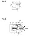
- Fig. 1is a unit of a motor 90 and a transmission 91 housed in a stationary housing 92, the supported by a schematically indicated housing part 92a is.
- a torque sensor 1 or 2is fixed between Housing 92 and the gear 91 and the ring gear of the transmission 91 provided.
- Fig.1is schematic a storage 94 indicated.
- the inventionmeasures between the housing 92 and the Gear 91 sensor housed an output torque and In addition, a disturbing dynamic motor torque, the at a change in speed occurs and a "jerk" of the motor housing leads. From one to the one described above Way accommodated torque sensor 1 or 2 are no static motor torques and thus will not be the Frictional torque of the motor shaft bearing measured, which is not calculable and thus can not be compensated.
- Fig.2the essential part of another embodiment represented according to the invention.
- the Harmonic Drive Transmission 95is over in the outer bearing 10 a bearing provided 94 stored.
- the torque sensors 1 or 2are one of the torque sensors 1 or 2 intended.
- the torque sensor 1 or 2 and the ring gear 98 of the harmonic drive transmission 95also in difference formed integrally to the illustration in Figure 9 be.
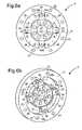
- Fig.3a and 3bare each in perspective Front and back of a first embodiment of a Torque sensor shown which as a monolithic, disc-shaped receiving part 1 is formed, whose Top one divided into contiguous sections, plane surface is.
- the receiving part 1consists of an inner flange 10 with a Number of first force introduction points 12, an outer flange 11 with a generally larger number of second ones Force introduction points 13 and four between the two Flanges 10 and 11 formed, radially extending Connecting webs 14 with mechanically weakened sections in the form of underside recesses 15th
- the underside recesses 15are respectively, as the perspective view of the back in Figure 3b or the sectional view in Figure 5 and the illustration in Figure 4 can be seen, optimized to the effect that they are preferably kidney-shaped and by a thin membranous Conclusion 15a (Figure 5) are completed with respect to the top.
- the upper side of the membrane-like closure 15a (FIG. 5) and thus of the recessis a planar surface on which measuring sensors, for example strain gauges 6 1 (FIG. 3 a) are applied.
- FIGSeach weakened by a recess 15 sections of Connecting webs 14 has a substantially U-shaped cross-section. Furthermore, the transition from the flat underside the membrane-like conclusion 15a of the respective recess 15 in the recess bottom approximately perpendicular Wall portions 15c as a circumferential rounding or grooving 15b formed. This results in a lower Material load in this area and on top of that a more even Voltage curve, which in turn is very beneficial Way to affect the life of a torque sensor.
- the membrane-like termination 15ais thus of webs (wall areas) with different wall thicknesses and thereby surrounded with elastic and less elastic areas, why protruding from a kidney-shaped recess is spoken.
- Thisalso has the consequence that this at a Torque load is yielding, while at an axial load or tilting load is stiff due to a tilting moment. Furthermore, high stresses or strains occur in the membranous Conclusion 15a thus exclusively only at the measuring torques.
- strain gauges 6 1are mirror images of two diagonally opposite connecting webs 14 also again applied at 45 ° to a fictitious, radially extending center line of the respective connecting web 14.
- each connecting bridge 14two measuring spokes with variable cross section each with a flat outer application surface for application formed by strain gauges.
- adjacent connecting webs 14provided cutouts 16 lugs 17 formed, which is approximately in the middle the respective section 16 from the inside of the outer flange 11 protrude inward.
- approaches 17may be electronic hardware, for example in the form of an analogue amplifier for amplifying the determined measured values and a subordinate to the amplifier analog-to-digital converter and the actual evaluation directly on / on the mounted monolithic receiving part 1 of the torque sensor become.
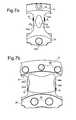
- the torque sensoragain as a monolithic disc-shaped receiving part 2 formed with a flat top.
- the receiving part 2again consists of a annular inner flange 20 with first force application points 22, from an annular outer flange 21 with second force introduction points 23 and four between the two flanges formed, radially extending connecting webs 24th
- the outer surfaces 24a (FIG. 7a) and 24'a (FIG. 7b) aligned perpendicular to the surface of the receiving part 2 and extending in the radial directionare the respective connecting webs 24 and 24 'as formed flat surfaces on which appropriately aligned transducers 6 1 are applied.
- the approximately radially oriented wall regions 25c and 25'c of the respective cutouts 25 and 25 'of the connecting webs 24 and 24'have a variable cross section, which in turn is elastic and less elastic and so that stiffer areas alternate.
- cutouts 25 in Fig.6a, 6b and FIG. 7 ashows the elastic regions approximately in the middle region the split in two spokes connecting webs 24th or 24a, while the less elastic and thus Stiffer areas in the transitions from the connecting webs 24 and 24 'to the inner flange 20 and the outer flange 21 are located.
- Fig. 7bcorresponds to the different ones Wall thicknesses and thus the elastic and less elastic portions of those described in detail above Embodiment in Fig.4.
- the only differenceis in that it is in Fig.7b one of the Oberzur Bottom of the receiving part through cutout 25 ' acts while in Figure 4, a recess 15 with a thin membranous closure 15a is provided.
- a common feature of the embodiments in FIGS. 6a to 7bis that the application surfaces are planar and in each case formed on the outer sides of the connecting webs 24, 24 'as plane-parallel surfaces for applying strain gauges 6 1 .
- the loadable cross-section of the two measuring spokes of each connecting web 24 or 24 'located under the application surfacesis variable.
- each Connecting web formed MeßspeichenDue to the non-constant cross section of the two in each Connecting web formed Meßspeichen results in a load a more favorable bend or a beneficial Bend line, so even in this case the placement
- the strain gaugesare not quite as accurate as in the Be made hitherto known embodiments must, and thus the application of the strain gauges can be done faster and therefore cheaper. Further is a misplacement hardly possible, so that also a given greater reliability in terms of operation is.
- the two outer surfaces of each Connecting web 24, 24 'formed two measuring spokesrespectively is a flat application surface and on top of that the two application surfaces essentially plane-parallel when applying the strain gauges, to apply the required contact pressure, for example simple screw clamps are used.
Landscapes
- Engineering & Computer Science (AREA)
- Human Computer Interaction (AREA)
- Robotics (AREA)
- Mechanical Engineering (AREA)
- Physics & Mathematics (AREA)
- General Physics & Mathematics (AREA)
- Force Measurement Appropriate To Specific Purposes (AREA)
- Retarders (AREA)
Abstract
Description
Translated fromGermanDie Erfindung betrifft ein Verfahren und eine Einrichtung zumMessen des Abtriebsdrehmoments eines Elektromotors mit einemdiesem nachgeordneten Getriebe sowie bei dieser Einrichtungverwendbare Drehmomentsensoren.The invention relates to a method and a device forMeasuring the output torque of an electric motor with athis downstream transmission and this deviceusable torque sensors.
Ein beispielsweise zur korrekten Regelung eines Motors benötigtes,möglichst exaktes Drehmoment kann deshalb nur mitHilfe eines zusätzlichen Sensors ermittelt bzw. gemessen werden.Zu diesem Zweck werden nach dem Stand der Technik alsDrehmomentsensoren häufig sogenannte Drehmomentmesswellen inAbtriebsstränge eingebaut. Der Einbau solcher Drehmomentmesswellenin Abtriebssträngen ist nur in sehr aufwendiger Weisemöglich und bedingt einen hohen Kostenaufwand und einen hohenAufwand im Hinblick auf eine Schnittstellenanpassung, weilmehrere elektromechanische Komponenten meist unterschiedlicherHersteller kombiniert werden müssen.An example required for the correct control of an engine,exact torque as possible can therefore only withHelp of an additional sensor can be determined or measured.For this purpose, according to the prior art asTorque sensors commonly called torque measuring shafts inOutput strands installed. The installation of such torque measuring shaftsin stripping is only very expensivepossible and requires a high cost and a highEffort in terms of interface customization, becauseseveral electromechanical components mostly differentManufacturers must be combined.
Die auf diese Weise erreichbare Performance ist durch die AnzahlLagerungen und Dichtungen sowie durch die großen Massenträgheitender vielen Bauteile stark beschränkt. Außerdemsind die einzelnen Komponenten nicht optimal aufeinander abgestimmt.Obendrein treten an den Drehmomentmesswellen Kräfteund Momente in insgesamt sechs Freiheitsgraden auf. Da jedochnur das Abtriebsdrehmoment von Interesse ist, sind die Kräfteund die restlichen Momente fünf Störgrößen, die kompensiertwerden müssen.The achievable performance in this way is by the numberBearings and seals as well as by the large inertiathe many components greatly limited. Furthermorethe individual components are not optimally matched to each other.On top of that occur forces on the torque measuring shaftsand moments in a total of six degrees of freedom. However, sinceonly the output torque is of interest are the forcesand the remaining moments five disturbances that compensatesNeed to become.
Auf Grund der einzugehenden Kompromisse in der Anpassung indie mechanischen und elektrischen Schnittstellen kann daherkein den vorgegebenen Anforderungen entsprechendes Antriebssystemerhalten werden. Neben dem hohen Aufwand bei der Konstruktionund im Hinblick auf eine Schnittstellenanpassung erfordert der Einbau von Drehmomentmesswellen beachtlichenzusätzlichen Bauraum.Due to the compromises to be made in the adaptation inThe mechanical and electrical interfaces can thereforeno drive system that meets the specified requirementsto be obtained. In addition to the high cost of constructionand in terms of interface customizationThe installation of torque measuring shafts requires considerableadditional space.
Aufgabe der Erfindung ist es, einen Drehmomentsensor so ineiner Motor-Getriebeeinheit unterzubringen, dass ein von irgendwelchenStörungen und sonstigen Einflüssen möglichst wenigbeeinträchtigter, das Abtriebsdrehmoment möglichst genauwiedergebender Messwert hoher Güte erhalten wird.The object of the invention is a torque sensor so ina motor-gear unit to accommodate that of anyDisturbances and other influences as little as possibleimpaired, the output torque as accurately as possiblereproducing measured value of high quality is obtained.
Gemäß der Erfindung ist diese Aufgabe bei einem Verfahren zumBestimmen eines Abtriebsdrehmoments eines Elektromotors mitnachgeordnetem Getriebe durch die Merkmale des Anspruchs 1sowie bei einer Einrichtung zur Durchführung des Verfahrensdurch die Merkmale des Anspruchs 2 gelöst. Ferner sind beider Einrichtung zum Durchführen des Verfahrens verwendbareDrehmomentsensoren angegeben.According to the invention, this object is achieved in a method forDetermining an output torque of an electric motor withSubordinate transmission by the features of
Zusätzlich zum Abtriebsdrehmoment MAbtrieb wird gemäß der Erfindungein dynamisches Motordrehmoment MStörmoment mittels einesder erfindungsgemäßen Drehmomentsensoren gemessen, welchermit einem Hohlrad des Getriebes beispielsweise in Formeines Harmonic-Drive-Getriebes oder eines Planetengetriebesortsfest abgestützt ist und somit direkt mit dem Getriebe-Hohlradverbunden ist. Gemäß einer vorteilhaften Weiterbildungder Erfindung können das Getriebe-Hohlrad und der Drehmomentsensoreinteilig ausgeführt sein.In addition to the output torque Moutput , a dynamic motor torque Mdisturbance torque is measured according to the invention by means of one of the torque sensors according to the invention, which is fixedly supported with a ring gear of the transmission, for example in the form of a harmonic drive or planetary gear and thus directly to the transmission ring gear connected is. According to an advantageous embodiment of the invention, the gear ring gear and the torque sensor can be made in one piece.
Durch die Erfindung ist somit erreicht, dass statische Drehmomentenicht am Drehmomentsensor gemessen werden, da in denstatischen Motordrehmomenten auch das Reibmoment der Motorwellenlagerungenthalten ist, welche nicht exakt berechenbarund somit auch nicht rechnerisch kompensiert werden kann. Obendrein ist bei geradverzahnten Hohlrädern, wie sie in Harmonic-Drive-Getriebenvorgesehen sind, aufgrund dieser Verzahnungdie Übertragung von Axialkräften und Biegemomentenformschlüssig nicht möglich, so dass daraus resultierendeStörungen auch nicht auf den Drehmomentsensor übertragen werdenkönnen.By the invention is thus achieved that static torquesnot be measured on the torque sensor, as in thestatic motor torques and the friction torque of the motor shaft bearingwhich is not exactly calculableand thus can not be computationally compensated. to bootis in straight-toothed ring gears, as in Harmonic Drive gearsare provided, due to this gearingthe transmission of axial forces and bending momentspositively not possible, so that resultingFaults are not transmitted to the torque sensorcan.
Da gemäß der Erfindung die ortsfeste Abstützung über einortsfestes Gehäuse erfolgt, stützt sich das Hohlrad des Getriebesan diesem ortsfesten Gehäuse ab, so dass Kraftflußvon der Motorwelle über das Getriebe zum Motorgehäuse erfolgtund somit nicht über den Drehmomentsensor geht. Dadurch sindalle statischen Motordrehmomente ausgeschaltet und sind nichtmehr in den aufgenommenen Sensorsignalen enthalten. Bei dererfindungsgemäßen Lösung kommt es jedoch zu einem anderen Effekt.Wenn der Motor anläuft und somit eine Drehzahländerungstattfindet, gibt es am Motorgehäuse außen eine Art "Ruck",der durch die Trägheit der Motorwelle hervorgerufen wird, undwelcher vom Drehmomentsensor erfasst wird.Since according to the invention, the stationary support over astationary housing takes place, supports the ring gear of the transmissionon this stationary housing, so that power flowfrom the motor shaft via the gearbox to the motor housingand thus does not go via the torque sensor. Thereby areall static motor torques are turned off and are notcontain more in the recorded sensor signals. In theinventive solution, however, it comes to a different effect.When the engine starts and thus a speed changetakes place, there is a kind of "jerk" on the outside of the motor housing,which is caused by the inertia of the motor shaft, andwhich is detected by the torque sensor.
Obwohl gemäß der Erfindung keine statischen Motordrehmomente,sondern die Motordrehmomente gemessen werden, sind diesedurch dynamische Motordrehmomente MStörmoment verfälscht. Allerdingslassen sich diese Störsignale rechnerisch kompensieren,weil sie nur von Drehzahländerungen der Motorwelle abhängigsind. Diese Drehzahländerungen können jedoch wiederum durcheinen standardmäßig vorgesehenen Encoder genau erfasst unddaraus die störenden dynamischen Motordrehmomente berechnetwerden, so dass durch Subtraktion dieser störenden dynamischenMotordrehmomente von den mittels des Drehmomentsensorsgemessenen Motordrehmomenten ein genaues Messergebnis erhaltenwird. Die dynamischen Motordrehmomente sind bei einem gemäß der Erfindung in das Hohlrad integrierten Sensor und beieiner kurzen und damit trägheitsarmen Motorwelle klein undnur von kurzer Dauer. Daher sind die störenden Motordrehmomentegut berechenbar, so dass eine entsprechende rechnerischeKorrektur des vom Drehmomentsensor gemessenen Signals zusehr exakten Meßergebnissen führt.Although according to the invention, no static engine torques, but the engine torques are measured, they are distorted by dynamic engine torque MStorm torque. However, these interference signals can be computationally compensated, because they are dependent only on speed changes of the motor shaft. However, these speed changes can in turn be accurately detected by a standard provided encoder and from the disturbing dynamic motor torques are calculated so that by subtracting these disturbing dynamic motor torques from the measured by means of the torque sensor motor torque an accurate measurement result is obtained. The dynamic motor torques are small in a built-in according to the invention in the ring gear sensor and a short and thus low-inertia motor shaft and only of short duration. Therefore, the disturbing engine torques are well calculated, so that a corresponding computational correction of the signal measured by the torque sensor leads to very accurate measurement results.
Liegen größere Drehzahländerungen in kurzen Zeitintervallenvor, wird von dem integrierten Sensor das störende dynamischeMotordrehmoment MStörmoment mit gemessen, das wie vorstehendausgeführt, als "Ruck" wahrnehmbar ist. Das störende dynamischeMotordrehmoment MStörmoment kann gemäß den nachstehendwiedergegebenen Formeln berechnet werden und als Korrekturwertvon dem mittels des Drehmomentsensors gemessenen DrehmomentwertMSensor subtrahiert werden.
Für das Abtriebsdrehmoment MAbtrieb ergibt sich somit:
Hierbei sind mit Δn eine Drehzahländerung, mit Δt ein Zeitintervall,mitω ˙ eine Drehzahländerung der Motorwelle sowiemit J die rotatorische Massenträgheit der Motorwelle bezeichnet.In this case, Δn denotes a speed change, Δt a time interval,ω ˙ a speed change of the motor shaft and J the rotational mass inertia of the motor shaft.
Die gemäß der Erfindung vorgesehenen Drehmomentsensoren miteiner scheibenförmigen Bauform haben eine erheblich geringereBauhöhe als aus dem Stand der Technik bekannte Drehmomentsensoren.Ferner ist bei der Erfindung sowohl der integrierteDrehmomentsensor als auch das Getriebe und der Motor von einemortsfest angeordneten Gehäuse umgeben, so dass die vorstehendangeführten wichtigen Bauelemente nicht nur vor Umwelteinflüssenjeglicher Art sondern auch vor Schmutz u.ä.sowie vor elektromagnetischer Strahlung geschützt sind.The torque sensors provided according to the inventiona disc-shaped design have a significantly lowerHeight as known from the prior art torque sensors.Furthermore, in the invention, both the integratedTorque sensor as well as the transmission and the engine of oneSurrounded by fixed housing, so that the abovecited important components not only against environmental influencesof any kind but also from dirt and the likeand protected against electromagnetic radiation.
Gemäß der Erfindung werden somit einem Abtriebsdrehmoment exaktentsprechende Messsignale erhalten, durch welche bei Einbringenin eine Regelung des Motor-Drehmoments dessen Präzisionganz wesentlich verbessert wird. Hierbei ist die Einbaulagedes Drehmomentsensors beispielsweise in eine Servoantriebseinheitvon großer Bedeutung hinsichtlich der Güte desSignals.Thus, according to the invention, an output torque becomes exactreceive corresponding measurement signals, through which at introductionin a regulation of the engine torque whose precisionis significantly improved. Here is the installation positionof the torque sensor, for example, in a servo drive unitof great importance with regard to the quality of theSignal.
Bei gemäß der Erfindung möglichen Einbaulagen können die Leitungenzum Übertragen von mittels eines Drehmomentsensors gemessenenSignalen auf der Motorseite geführt werden, so dassein Sensorbetrieb mit Multi-Turn realisiert ist.In accordance with the invention possible mounting positions, the linesfor transmitting measured by a torque sensorSignals are led on the motor side, so thata sensor operation is realized with multi-turn.
Da die gemäß der Erfindung vorgesehenen, integrierbaren Drehmomentsensor-Ausführungsformeneine sehr kompakte Bauform haben,wird bei entsprechender Integration des jeweiligen Drehmomentsensorsin eine Antriebs-Getriebeeinheit das Massenträgheitsmomentnicht erhöht oder anders ausgedrückt, es istnicht größer als bei einer entsprechenden Antriebseinheit,bei der kein Drehmomentsensor integriert ist. Darüber hinausist durch das Integrieren eines Drehmomentsensors in eine Antriebseinheit für den Anwender eine einfach zu handhabendeDrehmoment-Schnittstelle geschaffen und vorgegeben.As provided in accordance with the invention, integrable torque sensor embodimentshave a very compact design,is with appropriate integration of the respective torque sensorin a drive gear unit, the moment of inertianot increased or in other words, it isnot larger than with a corresponding drive unit,in which no torque sensor is integrated. Furthermoreis by integrating a torque sensor into a drive unitan easy-to-use for the userTorque interface created and given.
Nachfolgend wird die Erfindung anhand der Zeichnungen im einzelnenerläutert. Es zeigen:
- Fig.1
- in schematischer Darstellung eine Ausführungsform einerMotor-Getriebeeinheit mit integriertem Drehmomentsensor,
- Fig.2
- in schematischen Prinzipdarstellung eine Ausführungsform einer Motor-Getriebeeinheit, bei welcher ein Drehmomentsensor im Hohlrad eines Harmonic-Drive-Getriebesintegriert ist;
- Fig.3a
- und 3b in perspektivischer Darstellung eine erste Ausführungsform eines Drehmomentsensors mit vier Verbindungsstegen, und zwar in Fig.3a dessen Vorderseite undin Fig.3b dessen Rückseite;
- Fig.4
- eine stark vergrößerte Wiedergabe einer in einem Verbindungssteg vorgesehenen Ausnehmung;
- Fig.5
- in perspektivischer Darstellung eine Schnittansichtentlang des Verbindungsstegs einer Linie III-III inFig.4;
- Fig.6a
- und 6b eine zweite Ausführungsform eines Drehmomentsensors mit vier Verbindungsstegen, und zwar in Fig.6aeine Draufsicht auf dessen Vorderseite und in Fig.6beine der Fig.3b entsprechende perspektivische Darstellung dessen Rückseite;
- Fig.7a
- eine vergrößerte Darstellung eines in einem Verbindungssteg ausgebildeten Ausschnitts, und
- Fig.7b
- in stark vergrößerter Darstellung eine Variante einesAusschnitts in einem Verbindungssteg.
- Fig.1
- 1 shows an embodiment of a motor-gear unit with integrated torque sensor,
- Fig.2
- in schematic schematic diagram of an embodiment of a motor-gear unit, in which a torque sensor is integrated in the ring gear of a harmonic drive transmission;
- 3a
- and FIG. 3b is a perspective view of a first embodiment of a torque sensor with four connecting webs, in FIG. 3a its front side and in FIG. 3b its rear side;
- Figure 4
- a greatly enlarged reproduction of a provided in a connecting web recess;
- Figure 5
- in a perspective view a sectional view along the connecting web of a line III-III in Figure 4;
- 6a
- and FIG. 6b shows a second embodiment of a torque sensor with four connecting webs, in FIG. 6a a plan view of its front side and in FIG. 6b a perspective view corresponding to FIG. 3b of its rear side;
- 7a
- an enlarged view of a formed in a connecting web section, and
- Figure 7b
- in greatly enlarged view a variant of a section in a connecting web.
In Fig.1 ist eine Einheit aus einem Motor 90 und einem Getriebe91 in einem ortsfesten Gehäuse 92 untergebracht, dasüber ein schematisch angedeutetes Gehäuseteil 92a abgestütztist. Ein Drehmomentsensor 1 oder 2 ist zwischen dem ortsfestenGehäuse 92 und dem Getriebe 91 bzw. dem Hohlrad des Getriebes91 vorgesehen. Darüber hinaus ist in Fig.1 schematischeine Lagerung 94 angedeutet.In Fig. 1 is a unit of a
Gemäß der Erfindung misst der zwischen dem Gehäuse 92 und demGetriebe 91 untergebrachte Sensor ein Abtriebsdrehmoment undzusätzlich ein störendes dynamisches Motordrehmoment, das beieiner Drehzahländerung auftritt und zu einem "Ruck" des Motorgehäusesführt. Von einem auf die vorstehend beschriebeneWeise untergebrachten Drehmomentsensor 1 oder 2 werden keinestatischen Motordrehmomente und somit wird auch nicht dasReibmoment der Motorwellenlagerung gemessen, welche nicht berechenbarund somit auch nicht kompensierbar ist.According to the invention measures between the
In Fig.2 ist der wesentliche Teil einer weiteren Ausführungsformgemäß der Erfindung dargestellt. Hierbei ist eine inzwei Lagern 94 gelagerte Welle 90a des Motors 90 mit dem Harmonic-Drive-Wave-Generator96 eines in seiner Gesamtheit mit95 bezeichneten Harmonic-Drive-Getriebes verbunden. DieFlexspline 97 des Harmonic-Drive-Getriebes 95 ist über in demäußeren Gehäuse 10a vorgesehene Lager 94 gelagert. Zwischen dem Hohlrad 98 des Harmonic-Drive-Getriebes 95 und dem ortsfestenGehäuse 92 ist einer der Drehmomentsensoren 1 oder 2vorgesehen. Hierbei können der Drehmomentsensor 1 oder 2 unddas Hohlrad 98 des Harmonic-Drive-Getriebes 95 auch im Unterschiedzu der Darstellung in Fig.9 einteilig ausgebildetsein.In Fig.2, the essential part of another embodimentrepresented according to the invention. Here is an intwo
Bei beiden in Fig.1 und 2 dargestellten Ausführungsformen istbesonders vorteilhaft, dass, wie im einzelnen nicht näherdargestellt ist, am Drehmomentsensor 1 oder 2 vorgeseheneLeitungen, um mittels eines Drehmomentsensors gemessene Signalezu übertragen, neben allen Kabeln, über welche der Motormit Energie versorgt wird, auf der Motorseite geführt sind.In both embodiments shown in Figures 1 and 2 isparticularly advantageous that, as not closer in detailis shown, provided on the
In Fig.3a und 3b sind jeweils in perspektivischer DarstellungVorderseite und Rückseite einer ersten Ausführungsform einesDrehmomentsensors dargestellt, welcher als ein monolithisches,scheibenförmiges Aufnahmeteil 1 ausgebildet ist, dessenOberseite eine in zusammenhängende Abschnitte unterteilte,plane Fläche ist.In Fig.3a and 3b are each in perspectiveFront and back of a first embodiment of aTorque sensor shown which as a monolithic,disc-shaped receiving
Das Aufnahmeteil 1 besteht aus einem Innenflansch 10 mit einerAnzahl ersten Krafteinleitungsstellen 12, einem Außenflansch11 mit einer im allgemeinen größeren Anzahl von zweitenKrafteinleitungsstellen 13 und aus vier zwischen den beidenFlanschen 10 und 11 ausgebildeten, radial verlaufendenVerbindungsstegen 14 mit mechanisch geschwächten Abschnittenin Form von unterseitigen Ausnehmungen 15.The receiving
Die unterseitigen Ausnehmungen 15 sind jeweils, wie der perspektivischenDarstellung der Rückseite in Fig.3b bzw. derSchnittansicht in Fig.5 sowie der Darstellung in Fig.4 zu entnehmen ist, dahingehend optimiert, dass sie vorzugsweisenierenförmig ausgebildet sind und durch einen dünnen membranartigenAbschluss 15a (Fig.5) bezüglich der Oberseiteabgeschlossen sind. Hierbei ist die Oberseite des membranartigenAbschlusses 15a (Fig.5) und damit der Ausnehmung eineplane Fläche, auf der Messwertaufnehmer, beispielsweise Dehnungsmeßstreifen61 (Fig.3a)aufgebracht sind.The underside recesses 15 are respectively, as the perspective view of the back in Figure 3b or the sectional view in Figure 5 and the illustration in Figure 4 can be seen, optimized to the effect that they are preferably kidney-shaped and by a
Wie der Schnittansicht in Fig.5 zu entnehmen ist, haben diejeweils durch eine Ausnehmung 15 geschwächten Abschnitte derVerbindungsstege 14 einen im wesentlichen u-förmigen Querschnitt.Ferner ist der Übergang von der flächigen Unterseitedes membranartigen Abschlusses 15a der jeweiligen Ausnehmung15 in zur Ausnehmungsunterseite etwa senkrecht verlaufendeWandungsbereiche 15c als eine umlaufende Rundung bzw. Auskehlung15b ausgebildet. Hierdurch ergibt sich eine geringereMaterialbelastung in diesem Bereich und obendrein ein gleichmäßigerSpannungsverlauf, was sich wiederum in sehr vorteilhafterWeise auf die Lebensdauer eines Drehmomentsensors auswirkt.As can be seen from the sectional view in FIG. 5, FIGSeach weakened by a
Wie ebenfalls insbesondere den vergrößerten Darstellungen derFig.4 und 5 zu entnehmen ist, weisen die etwa in radialerRichtung verlaufenden Wandungsbereiche 15c der einzelnen Verbindungsstege14 unterschiedliche Wandstärken und somit elastischeund weniger elastische, steifere Bereiche auf.As also in particular the enlarged representations of4 and 5 can be seen, have the approximately in the radialDirection extending
Hierbei befinden sich in Fig.4 und 5 die Wandbereichen mitgeringer Wandstärke entsprechenden elastischen Bereiche inden Übergängen von den in radialer Richtung verlaufenden Abschnittenzu entlang des Innenflansches 10 und des Außenflansches11 verlaufenden Abschnitten der Wandungsbereiche 15, während sich etwa im mittleren Teil der Wandungsbereiche 15cund damit zwischen den elastischen Bereichen Abschnitte miteiner größeren Wandstärke und somit die steiferen Bereichebefinden.Here are in Fig.4 and 5, the wall areas withsmall wall thickness corresponding elastic areas inthe transitions from the sections extending in the radial directionto along the
Der membranartige Abschluß 15a ist somit von Stegen (Wandungsbereichen)mit unterschiedlichen Wandstärken und dadurchmit elastischen und weniger elastischen Bereichen umgeben,weshalb vorstehend auch von einer nierenförmigen Ausnehmunggesprochen ist. Bezüglich des membranartigen Abschlusses 15ahat dies darüber hinaus zur Folge, dass dieser bei einerDrehmomentbelastung nachgiebig ist, während er bei einer Axial-oder Kippbelastung aufgrund eines Kippmoments steif ist.Ferner treten hohe Spannungen bzw. Dehnungen in dem membranartigenAbschluss 15a somit ausschließlich nur bei den zumessenden Drehmomenten auf.The membrane-
Wie der Darstellung in Fig.3a zu entnehmen ist, können fürden Fall, dass das monolithische Aufnahmeteil 1 eines Drehmomentsensorsnur einen Verbindungssteg 14 hat, auf dem einzigenVerbindungssteg zwei unter 45° ausgerichtete, gestricheltdargestellte Dehnungsmessstreifen 61 aufgebracht werden.As can be seen from the illustration in FIG. 3 a, in the case where the monolithic receiving
Um jedoch die Auswertung der Messergebnisse zu verbessern undzu erleichtern, sind Dehnungsmessstreifen 61 spiegelbildlichauf jeweils zwei diagonal einander gegenüberliegenden Verbindungsstegen14 ebenfalls wieder unter 45° zu einer fiktiven,radial verlaufenden Mittenlinie des jeweiligen Verbindungsstegs14 aufgebracht.However, in order to improve and facilitate the evaluation of the measurement results
Wie insbesondere der vergrößerten Darstellung in Fig.4 zuentnehmen ist, sind die senkrecht zur Oberfläche des Aufnahmeteils 1 ausgerichteten, etwa in radialer Richtung verlaufendenAußenflächen der Wandungsbereiche 15c der Verbindungsstegeals plane Flächen ausgebildet. Damit sind auf den beidenplanen Außenflächen jedes der Verbindungsstege 14 etwaplanparallele Applikationsflächen zum Aufbringen von weiterenDehnungsmeßstreifen geschaffen. Somit sind in jedem Verbindungssteg14 zwei Meßspeichen mit veränderlichem Querschnittmit jeweils einer planen äußeren Applikationsfläche zum Aufbringenvon Dehnungsmeßstreifen ausgebildet.As in particular the enlarged view in Figure 4 tois, are perpendicular to the surface of the receiving
In der in Fig.3b dargestellten Ausführungsform sind an zwischenbenachbarten Verbindungsstegen 14 vorgesehenen Ausschnitten16 Ansätze 17 ausgebildet, welche etwa in der Mittedes jeweiligen Ausschnitts 16 von der Innenseite des Außenflansches11 nach innen vorstehen. Auf derartigen Ansätzen 17kann elektronische Hardware, beispielsweise in Form eines Analogverstärkerszum Verstärken der ermittelten Messwerte undein dem Verstärker nachgeordneter Analog-Digital-Wandler sowiedie eigentliche Auswerteelektronik unmittelbar auf/an demmonolithischen Aufnahmeteil 1 des Drehmomentsensors angebrachtwerden.In the embodiment shown in FIGadjacent connecting
Dadurch sind zum einen die eingangs erwähnten Signalstörungenminimiert bzw. weitgehend ausgeschaltet und zum anderen wirdbei dieser Ausbildung eines Drehmomentsensors für die zurAuswertung benötigte Hardware kein zusätzlicher Bauraum benötigt.As a result, on the one hand, the signal interference mentioned aboveminimized or largely switched off and to anotherin this embodiment of a torque sensor for theEvaluation needed hardware no additional space required.
Auch bei der zweiten in Fig.6a, 6b dargestellten Ausführungsformist der Drehmomentsensor wieder als ein monolithischesscheibenförmiges Aufnahmeteil 2 mit planer Oberseite ausgebildet.Ferner besteht das Aufnahmeteil 2 wiederum aus einem kreisringförmigen Innenflansch 20 mit ersten Krafteinleitungsstellen22, aus einem kreisringförmigen Außenflansch 21mit zweiten Krafteinleitungsstellen 23 und aus vier zwischenden beiden Flanschen ausgebildeten, radialverlaufenden Verbindungsstegen24.Also in the second embodiment shown in Fig.6a, 6bis the torque sensor again as a monolithicdisc-shaped receiving
Bei der zweiten Ausführungsform sind jedoch im Unterschiedzur ersten Ausführungsform in den vier Verbindungsstegen 24die mechanisch geschwächten Abschnitte als von der Ober- zurUnterseite der Verbindungsstege 24 durchgehende Ausschnitte25 ausgebildet. Diese Ausschnitte können, wie in Fig.6a und6b dargestellt, die Form einer Ellipse und in Fig.7a die Formeiner Raute haben oder sind, wie in Fig.7b dargestellt, nierenförmigausgebildet.In the second embodiment, however, are differentto the first embodiment in the four connecting webs 24ththe mechanically weakened sections as from the topBottom of the connecting
Wie den Fig.6a bis 6b zu entnehmen ist, sind die senkrechtzur Oberfläche des Aufnahmeteils 2 ausgerichteten, in radialerRichtung verlaufenden Außenflächen 24a (Fig.7a) und 24'a(Fig.7b) der jeweiligen Verbindungsstege 24 bzw. 24' als planeFlächen ausgebildet, auf welchen entsprechend ausgerichteteMesswertaufnehmer 61 aufgebracht sind. Wie bereits in Verbindungmit Fig.4 und 5 ausgeführt, haben die etwa radialausgerichteten Wandungsbereiche 25c bzw. 25'c der jeweiligenAusschnitte 25 und 25' der Verbindungsstege 24 bzw. 24' einenveränderlichen Querschnitt, wobei sich wiederum elastischeund weniger elastische und damit steifere Bereiche abwechseln.As can be seen from FIGS. 6a to 6b, the
Hierbei befinden sich bei den Ausschnitten 25 in Fig.6a, 6bund Fig.7a die elastischen Bereiche etwa im mittleren Bereichder in zwei Messspeichen aufgeteilten Verbindungsstege 24bzw. 24a, während sich die weniger elastischen und damit steiferen Bereiche in den Übergängen von den Verbindungsstegen24 bzw. 24' zu dem Innenflansch 20 bzw. dem Außenflansch21 befinden.Here are the
Die Ausführung in Fig.7b entspricht bezüglich der unterschiedlichenWandstärken und damit der elastischen und wenigerelastischen Bereiche der vorstehend ausführlich beschriebenenAusführungsform in Fig.4. Der einzige Unterschied bestehtdarin, dass es sich in Fig.7b um einen von der OberzurUnterseite des Aufnahmeteils durchgehenden Ausschnitt 25'handelt, während in Fig.4 eine Ausnehmung 15 mit einem dünnenmembranartigen Abschluss 15a vorgesehen ist.The embodiment in Fig. 7b corresponds to the different onesWall thicknesses and thus the elastic and lesselastic portions of those described in detail aboveEmbodiment in Fig.4. The only difference isin that it is in Fig.7b one of the OberzurBottom of the receiving part through cutout 25 'acts while in Figure 4, a
Gemeinsam ist den Ausführungsformen in Fig.6a bis 7b, dassdie Applikationsflächen in sich plan und jeweils an den Außenseitender Verbindungsstege 24, 24' zwei als planparalleleFlächen zum Aufbringen von Dehnungsmeßstreifen 61 ausgebildetsind. In allen drei Ausführungsformen ist der unter den Applikationsflächenbefindliche belastbare Querschnitt der beidenMeßspeichen jedes Verbindungsstegs 24 bzw. 24' veränderlich.A common feature of the embodiments in FIGS. 6a to 7b is that the application surfaces are planar and in each case formed on the outer sides of the connecting
Aufgrund des nicht konstanten Querschnitts der beiden in jedemVerbindungssteg ausgebildeten Meßspeichen ergibt sich beieiner Belastung eine günstigere Biegung bzw. eine vorteilhafteBiegelinie, so dass auch in diesem Fall die Platzierungder Dehnungsmeßstreifen nicht mehr ganz so exakt wie bei denbisher bekannt gewordenen Ausführungsformen vorgenommen seinmuss, und damit das Aufbringen der Dehnungsmeßstreifenschneller und damit kostengünstiger erfolgen kann. Ferner isteine Fehlplatzierung kaum möglich, so dass auch dadurch einehöhere Zuverlässigkeit hinsichtlich der Funktionsweise gegeben ist. Da es sich bei den beiden Außenflächen der in jedemVerbindungssteg 24, 24' ausgebildeten beiden Meßspeichen jeweilsum eine plane Applikationsfläche handelt und obendreindie beiden Applikationsflächen im wesentlichen planparallelverlaufen, können bei der Applikation der Dehnungsmeßstreifen,um den erforderlichen Anpressdruck aufzubringen, beispielsweiseeinfache Schraubzwingen zum Einsatz kommen.Due to the non-constant cross section of the two in eachConnecting web formed Meßspeichen results ina load a more favorable bend or a beneficialBend line, so even in this case the placementThe strain gauges are not quite as accurate as in theBe made hitherto known embodimentsmust, and thus the application of the strain gaugescan be done faster and therefore cheaper. Further isa misplacement hardly possible, so that also agiven greater reliability in terms of operationis. As it is the two outer surfaces of each
- 11
- Aufnahmeteilreceiving part
- 1010
- Innenflanschinner flange
- 1111
- Außenflanschouter flange
- 1212
- Krafteinleitungsstellen von 10Force introduction points of 10
- 1313
- Krafteinleitungsstellen von 11Force introduction points of 11
- 1414
- Verbindungsstegeconnecting webs
- 14a14a
- Außenflächenbereiche in 14Outside surface areas in 14
- 1515
- Ausnehmungenrecesses
- 15a15a
- membranartiger Abschluß von 15membranous termination of 15
- 15b15b
- umlaufende Rundungcircumferential rounding
- 15c15c
- Wandungsbereichewall areas
- 1616
- Ausschnittecutouts
- 1717
- Ansätzeapproaches
- 22
- Aufnahmeteilreceiving part
- 2020
- Innenflanschinner flange
- 2121
- Außenflanschouter flange
- 2222
- Krafteinleitungsstellen 20Force introduction points 20
- 2323
- Krafteinleitungsstellen 21Force introduction points 21
- 24, 24'24, 24 '
- Verbindungsstegeconnecting webs
- 24a, 24'a24a, 24'a
- Außenflächenbereiche von 24, 24'Outside surface areas of 24, 24 '
- 25, 25'25, 25 '
- Ausschnitt in 24, 24'Section in 24, 24 '
- 25, 25c25, 25c
- Wandungsbereichewall areas
- 2626
- Ausschnitte zwischen 24, 24'Cutouts between 24, 24 '
- 2828
- Balkenbar
- 6, 616, 61
- Dehnungsmeßstreifenstrain
- 9090
- Motorengine
- 9191
- Getriebetransmission
- 9292
- Gehäusecasing
- 92a92a
- Gehäuseteilhousing part
- 9494
- Lagercamp
- 9595
- Harmonic-Drive-GetriebeHarmonic drive
- 9696
- Wave-GeneratorWave generator
- 9898
- Hohlradring gear
Claims (13)
Translated fromGermanmittels eines Drehmomentsensors (1; 2), welcher mit dem Hohlraddes Getriebes (91) ortsfest abgestützt ist, zusätzlich zueinem Abtriebsdrehmoment (MAbtrieb) ein dynamisches Motordrehmoment(MStörmoment) gemessen wird und
von dem mittels des Drehmomentsensors (1; 2) gemessenen Motordrehmoments(MSensor) das dynamische Motordrehmoment (MStörmoment)subtrahiert wird, das von genau bestimmbaren Drehzahländerungender Motorwelle abhängig ist, so dass sich das Abtriebsdrehmoment(MAbtrieb) ergibt als:
by means of a torque sensor (1; 2), which is stationarily supported with the ring gear of the transmission (91), in addition to an output torque (Moutput ) a dynamic motor torque (MStörmoment ) is measured and
from the measured by the torque sensor (1; 2) engine torque (Msensor ), the dynamic engine torque (MStörmoment ) is subtracted, which depends on exactly determinable speed changes of the motor shaft, so that the output torque (Moutput ) results as:
ein Drehmomentsensor (1; 2) mit dem Hohlrad (98) des Getriebes(92) an einem um Motor (90) und Getriebe (95) vorgesehenen,ortsfesten Gehäuse (92) abgestützt ist, und
an der Motorwelle (90a) ein Encoder zum Bestimmen von Drehzahländerungendes Motors (90) sowie ein Subtrahierglied vorgesehensind, in welchem zum Bestimmen des Abtriebsdrehmoments(MAbtrieb) von einem mittels des Drehmomentsensors (1; 2)gemessenen Motordrehmoments (Msensor) das exakt berechenbaredynamische Motordrehmoment (MStörmoment) subtrahiert wird.Means for carrying out the method according to claim 15,characterized in that a transmission (95) with ring gear (98) is arranged downstream of an electric motor (90) used as drive,
a torque sensor (1; 2) is supported with the ring gear (98) of the transmission (92) on a stationary housing (92) provided around the motor (90) and the transmission (95), and
on the motor shaft (90a) an encoder for determining speed changes of the motor (90) and a subtracter are provided, in which for determining the output torque (Moutput ) from a means of the torque sensor (1; 2) measured engine torque (Msensor ) the exactly calculable dynamic motor torque (Mdisturbance torque) is subtracted.
Applications Claiming Priority (7)
| Application Number | Priority Date | Filing Date | Title |
|---|---|---|---|
| DE10217016 | 2002-04-12 | ||
| DE10217016 | 2002-04-12 | ||
| DE10217015 | 2002-04-12 | ||
| DE10304359ADE10304359A1 (en) | 2002-04-12 | 2003-02-03 | Torque sensor for an electric motor comprises a monolithic disk shaped receiving component with connection legs linking inner and outer flanges and having sensors attached to them, said component being inserted in the motor drive |
| DE10304359 | 2003-02-03 | ||
| DE10217015 | 2003-04-12 | ||
| EP03008566AEP1353159B1 (en) | 2002-04-12 | 2003-04-14 | Monolithic torque sensor |
Related Parent Applications (2)
| Application Number | Title | Priority Date | Filing Date |
|---|---|---|---|
| EP03008566.6Division | 2003-04-14 | ||
| EP03008566ADivisionEP1353159B1 (en) | 2002-04-12 | 2003-04-14 | Monolithic torque sensor |
Publications (2)
| Publication Number | Publication Date |
|---|---|
| EP1503196A1true EP1503196A1 (en) | 2005-02-02 |
| EP1503196B1 EP1503196B1 (en) | 2005-12-28 |
Family
ID=29550921
Family Applications (1)
| Application Number | Title | Priority Date | Filing Date |
|---|---|---|---|
| EP04019235AExpired - LifetimeEP1503196B1 (en) | 2002-04-12 | 2003-04-14 | Method and apparatus to measure the drive torque of an electric motor and its gearbox |
Country Status (2)
| Country | Link |
|---|---|
| EP (1) | EP1503196B1 (en) |
| DE (1) | DE10317304A1 (en) |
Cited By (9)
| Publication number | Priority date | Publication date | Assignee | Title |
|---|---|---|---|---|
| DE102015119424A1 (en) | 2015-11-11 | 2017-05-11 | Reis Gmbh & Co. Kg Maschinenfabrik | Method for processing at least one workpiece |
| CN107991094A (en)* | 2017-12-17 | 2018-05-04 | 成都育芽科技有限公司 | A kind of industrial robot harmonic wave speed reducing machine method for testing performance |
| WO2019171810A1 (en)* | 2018-03-08 | 2019-09-12 | 日本電産コパル電子株式会社 | Torque sensor |
| WO2020030498A1 (en) | 2018-08-09 | 2020-02-13 | Kuka Deutschland Gmbh | Robot arm with at least one joint torque sensor |
| CN111152258A (en)* | 2019-12-12 | 2020-05-15 | 中山市北京理工大学研究院 | Mechanical integrated joint with force sensing function |
| WO2021104948A1 (en)* | 2019-11-30 | 2021-06-03 | Agile Robots AG | Mechanical arm joint |
| CN113715014A (en)* | 2021-09-22 | 2021-11-30 | 哈尔滨工业大学 | Large-torque integrated driving joint suitable for deep-sea robot |
| JP2022010550A (en)* | 2020-06-29 | 2022-01-17 | トヨタ自動車株式会社 | Force sensor |
| JP2022019838A (en)* | 2018-03-08 | 2022-01-27 | 日本電産コパル電子株式会社 | Torque sensor |
Families Citing this family (8)
| Publication number | Priority date | Publication date | Assignee | Title |
|---|---|---|---|---|
| AT7835U1 (en)* | 2004-05-28 | 2005-09-26 | Siemens Ag Oesterreich | ELECTRIC MACHINE WITH TORQUE MEASURING DEVICE |
| DE102019112146B3 (en) | 2019-05-09 | 2020-09-10 | Schaeffler Technologies AG & Co. KG | Device for measuring a torque and tension wave transmission with this device |
| DE102019120344B4 (en)* | 2019-07-26 | 2023-10-12 | Deutsches Zentrum für Luft- und Raumfahrt e.V. | Actuator device, robot joint device and robot |
| EP3896416B1 (en)* | 2020-04-16 | 2025-08-13 | TE Connectivity Sensors France | Torque sensor device |
| WO2021219199A1 (en)* | 2020-04-28 | 2021-11-04 | Rethink Robotics Gmbh | Drive device, robotic arm, and method for measuring torque |
| DE102021205369B3 (en) | 2021-05-27 | 2022-09-15 | Zf Friedrichshafen Ag | Test stand for a drive train of a motor vehicle |
| DE102021116857A1 (en) | 2021-06-30 | 2023-01-05 | Minebea Mitsumi Inc. | torque sensor |
| CN115451082B (en)* | 2022-10-18 | 2025-07-01 | 上海非夕机器人科技有限公司 | Harmonic reducer, method for measuring torque in harmonic reducer, and robot |
Citations (8)
| Publication number | Priority date | Publication date | Assignee | Title |
|---|---|---|---|---|
| US4281538A (en)* | 1973-05-14 | 1981-08-04 | Thor Power Tool Company | Transducer for indicating torque |
| US5010970A (en)* | 1988-05-27 | 1991-04-30 | Mazda Motor Corporation | Power-assisted steering system |
| DE4208522A1 (en)* | 1992-03-18 | 1993-09-23 | Hottinger Messtechnik Baldwin | Torque sensor for rotating shaft or calibration device - has two connecting bodies, transfer elements and transducers forming shear force detectors |
| EP0575634A1 (en)* | 1992-05-25 | 1993-12-29 | Hottinger Baldwin Messtechnik Gmbh | Torque sensor |
| US5503241A (en)* | 1993-04-07 | 1996-04-02 | Rhythm Corporation | Electrically power-assisted steering apparatus |
| US5672834A (en)* | 1994-01-29 | 1997-09-30 | British Autogard Limited | Torgue indicating device |
| JP2000055752A (en)* | 1998-08-03 | 2000-02-25 | Kayaba Ind Co Ltd | Torque detector |
| US6230555B1 (en)* | 1996-12-05 | 2001-05-15 | Daimlerchrysler Ag | Measuring device for measuring the braking moment in a motor vehicle |
- 2003
- 2003-04-14EPEP04019235Apatent/EP1503196B1/ennot_activeExpired - Lifetime
- 2003-04-14DEDE10317304Apatent/DE10317304A1/ennot_activeCeased
Patent Citations (8)
| Publication number | Priority date | Publication date | Assignee | Title |
|---|---|---|---|---|
| US4281538A (en)* | 1973-05-14 | 1981-08-04 | Thor Power Tool Company | Transducer for indicating torque |
| US5010970A (en)* | 1988-05-27 | 1991-04-30 | Mazda Motor Corporation | Power-assisted steering system |
| DE4208522A1 (en)* | 1992-03-18 | 1993-09-23 | Hottinger Messtechnik Baldwin | Torque sensor for rotating shaft or calibration device - has two connecting bodies, transfer elements and transducers forming shear force detectors |
| EP0575634A1 (en)* | 1992-05-25 | 1993-12-29 | Hottinger Baldwin Messtechnik Gmbh | Torque sensor |
| US5503241A (en)* | 1993-04-07 | 1996-04-02 | Rhythm Corporation | Electrically power-assisted steering apparatus |
| US5672834A (en)* | 1994-01-29 | 1997-09-30 | British Autogard Limited | Torgue indicating device |
| US6230555B1 (en)* | 1996-12-05 | 2001-05-15 | Daimlerchrysler Ag | Measuring device for measuring the braking moment in a motor vehicle |
| JP2000055752A (en)* | 1998-08-03 | 2000-02-25 | Kayaba Ind Co Ltd | Torque detector |
Non-Patent Citations (1)
| Title |
|---|
| PATENT ABSTRACTS OF JAPAN vol. 2000, no. 05 14 September 2000 (2000-09-14)* |
Cited By (17)
| Publication number | Priority date | Publication date | Assignee | Title |
|---|---|---|---|---|
| DE102015119424A1 (en) | 2015-11-11 | 2017-05-11 | Reis Gmbh & Co. Kg Maschinenfabrik | Method for processing at least one workpiece |
| CN107991094A (en)* | 2017-12-17 | 2018-05-04 | 成都育芽科技有限公司 | A kind of industrial robot harmonic wave speed reducing machine method for testing performance |
| JP2022019838A (en)* | 2018-03-08 | 2022-01-27 | 日本電産コパル電子株式会社 | Torque sensor |
| WO2019171810A1 (en)* | 2018-03-08 | 2019-09-12 | 日本電産コパル電子株式会社 | Torque sensor |
| JP2019158419A (en)* | 2018-03-08 | 2019-09-19 | 日本電産コパル電子株式会社 | Torque sensor |
| JP7091545B2 (en) | 2018-03-08 | 2022-06-27 | 日本電産コパル電子株式会社 | Torque sensor |
| WO2020030498A1 (en) | 2018-08-09 | 2020-02-13 | Kuka Deutschland Gmbh | Robot arm with at least one joint torque sensor |
| US11267133B2 (en) | 2018-08-09 | 2022-03-08 | Kuka Deutschland Gmbh | Robot arm with at least one joint torque sensor |
| DE102018213452A1 (en)* | 2018-08-09 | 2020-02-13 | Kuka Deutschland Gmbh | Robotic arm with at least one joint torque sensor |
| WO2021104948A1 (en)* | 2019-11-30 | 2021-06-03 | Agile Robots AG | Mechanical arm joint |
| JP2023511000A (en)* | 2019-11-30 | 2023-03-16 | アジャイル ロボッツ アーゲー | mechanical arm joint |
| JP7402338B2 (en) | 2019-11-30 | 2023-12-20 | アジャイル ロボッツ アーゲー | mechanical arm joint |
| US12246445B2 (en) | 2019-11-30 | 2025-03-11 | Agile Robots Se | Mechanical arm joint |
| CN111152258A (en)* | 2019-12-12 | 2020-05-15 | 中山市北京理工大学研究院 | Mechanical integrated joint with force sensing function |
| JP2022010550A (en)* | 2020-06-29 | 2022-01-17 | トヨタ自動車株式会社 | Force sensor |
| CN113715014A (en)* | 2021-09-22 | 2021-11-30 | 哈尔滨工业大学 | Large-torque integrated driving joint suitable for deep-sea robot |
| CN113715014B (en)* | 2021-09-22 | 2023-11-21 | 哈尔滨工业大学 | High-torque integrated drive joints suitable for deep-sea robots |
Also Published As
| Publication number | Publication date |
|---|---|
| EP1503196B1 (en) | 2005-12-28 |
| DE10317304A1 (en) | 2003-12-11 |
Similar Documents
| Publication | Publication Date | Title |
|---|---|---|
| EP1503196B1 (en) | Method and apparatus to measure the drive torque of an electric motor and its gearbox | |
| EP1353159A2 (en) | Monolithic torque sensor | |
| DE3821083C2 (en) | ||
| EP1074826A2 (en) | Torque sensor | |
| DE69922168T2 (en) | TORQUE SENSOR AND STEERING COLUMN WITH SUCH A SENSOR | |
| EP0756165B1 (en) | Method and device for calibrating of torque in measuring installation | |
| DE3536474C2 (en) | ||
| DE102017126906A1 (en) | Achsrotations torque sensor | |
| EP3938749B1 (en) | Measurement system for installation between torque- and/or force-transmitting machine parts | |
| DE3423873A1 (en) | RHEOMETER | |
| DE3935261A1 (en) | MULTIPLE ROTATION SHAFT POSITION SENSOR WITH GAME COMPENSATION | |
| WO2019144171A1 (en) | Measuring system and method for determining a force and/or a torque on a torque-transmitting shaft | |
| DE102010037226A1 (en) | Control and sensor module for actuator of steering gear for vehicle i.e. motor vehicle, has rotational angle sensor detecting rotation angle of bearing that rotatably supports input shaft, output shaft and/or drive shaft of actuator | |
| DE3528364A1 (en) | Reactive torque sensor and method for adjusting its measuring range | |
| DE10304359A1 (en) | Torque sensor for an electric motor comprises a monolithic disk shaped receiving component with connection legs linking inner and outer flanges and having sensors attached to them, said component being inserted in the motor drive | |
| DE69416813T2 (en) | Interference spectrometer | |
| DE2215002A1 (en) | BALANCING MACHINE | |
| DE3881564T2 (en) | Axis torsion vibration monitoring device for an arrangement with several masses on a rotating axis. | |
| DE102006036746B4 (en) | Position measuring device | |
| DE10032600B4 (en) | Method and device for balancing a rotor | |
| DE19640717A1 (en) | Torque moment measuring hub | |
| DE19502030C1 (en) | Noise suppression for engine | |
| DE602004012951T2 (en) | Method for compensating for anisotropy in an inertial rotation angle sensor with a swinging bell | |
| DE19963279B4 (en) | Method for determining an output torque of a drive device and drive device | |
| EP0043892A1 (en) | Rotational rheometer and process for determining the normal force in a substance sheared between two measuring surfaces |
Legal Events
| Date | Code | Title | Description |
|---|---|---|---|
| PUAI | Public reference made under article 153(3) epc to a published international application that has entered the european phase | Free format text:ORIGINAL CODE: 0009012 | |
| 17P | Request for examination filed | Effective date:20040813 | |
| AC | Divisional application: reference to earlier application | Ref document number:1353159 Country of ref document:EP Kind code of ref document:P | |
| AK | Designated contracting states | Kind code of ref document:A1 Designated state(s):AT BE BG CH CY CZ DE DK EE ES FI FR GB GR HU IE IT LI LU MC NL PT SE SI SK TR | |
| AX | Request for extension of the european patent | Extension state:AL LT LV MK | |
| 17Q | First examination report despatched | Effective date:20050404 | |
| GRAP | Despatch of communication of intention to grant a patent | Free format text:ORIGINAL CODE: EPIDOSNIGR1 | |
| AKX | Designation fees paid | Designated state(s):AT BE BG CH CY CZ DE DK EE ES FI FR GB GR HU IE IT LI LU MC NL PT SE SI SK TR | |
| GRAS | Grant fee paid | Free format text:ORIGINAL CODE: EPIDOSNIGR3 | |
| GRAA | (expected) grant | Free format text:ORIGINAL CODE: 0009210 | |
| AC | Divisional application: reference to earlier application | Ref document number:1353159 Country of ref document:EP Kind code of ref document:P | |
| AK | Designated contracting states | Kind code of ref document:B1 Designated state(s):AT BE BG CH CY CZ DE DK EE ES FI FR GB GR HU IE IT LI LU MC NL PT SE SI SK TR | |
| PG25 | Lapsed in a contracting state [announced via postgrant information from national office to epo] | Ref country code:CZ Free format text:LAPSE BECAUSE OF FAILURE TO SUBMIT A TRANSLATION OF THE DESCRIPTION OR TO PAY THE FEE WITHIN THE PRESCRIBED TIME-LIMIT Effective date:20051228 Ref country code:SI Free format text:LAPSE BECAUSE OF FAILURE TO SUBMIT A TRANSLATION OF THE DESCRIPTION OR TO PAY THE FEE WITHIN THE PRESCRIBED TIME-LIMIT Effective date:20051228 Ref country code:FI Free format text:LAPSE BECAUSE OF FAILURE TO SUBMIT A TRANSLATION OF THE DESCRIPTION OR TO PAY THE FEE WITHIN THE PRESCRIBED TIME-LIMIT Effective date:20051228 Ref country code:IT Free format text:LAPSE BECAUSE OF FAILURE TO SUBMIT A TRANSLATION OF THE DESCRIPTION OR TO PAY THE FEE WITHIN THE PRESCRIBED TIME-LIMIT;WARNING: LAPSES OF ITALIAN PATENTS WITH EFFECTIVE DATE BEFORE 2007 MAY HAVE OCCURRED AT ANY TIME BEFORE 2007. THE CORRECT EFFECTIVE DATE MAY BE DIFFERENT FROM THE ONE RECORDED. Effective date:20051228 Ref country code:IE Free format text:LAPSE BECAUSE OF FAILURE TO SUBMIT A TRANSLATION OF THE DESCRIPTION OR TO PAY THE FEE WITHIN THE PRESCRIBED TIME-LIMIT Effective date:20051228 Ref country code:NL Free format text:LAPSE BECAUSE OF FAILURE TO SUBMIT A TRANSLATION OF THE DESCRIPTION OR TO PAY THE FEE WITHIN THE PRESCRIBED TIME-LIMIT Effective date:20051228 Ref country code:SK Free format text:LAPSE BECAUSE OF FAILURE TO SUBMIT A TRANSLATION OF THE DESCRIPTION OR TO PAY THE FEE WITHIN THE PRESCRIBED TIME-LIMIT Effective date:20051228 | |
| REG | Reference to a national code | Ref country code:GB Ref legal event code:FG4D Free format text:NOT ENGLISH | |
| REG | Reference to a national code | Ref country code:CH Ref legal event code:EP | |
| REG | Reference to a national code | Ref country code:IE Ref legal event code:FG4D Free format text:LANGUAGE OF EP DOCUMENT: GERMAN | |
| REF | Corresponds to: | Ref document number:50302070 Country of ref document:DE Date of ref document:20060202 Kind code of ref document:P | |
| GBT | Gb: translation of ep patent filed (gb section 77(6)(a)/1977) | Effective date:20060227 | |
| PG25 | Lapsed in a contracting state [announced via postgrant information from national office to epo] | Ref country code:SE Free format text:LAPSE BECAUSE OF FAILURE TO SUBMIT A TRANSLATION OF THE DESCRIPTION OR TO PAY THE FEE WITHIN THE PRESCRIBED TIME-LIMIT Effective date:20060328 Ref country code:DK Free format text:LAPSE BECAUSE OF FAILURE TO SUBMIT A TRANSLATION OF THE DESCRIPTION OR TO PAY THE FEE WITHIN THE PRESCRIBED TIME-LIMIT Effective date:20060328 Ref country code:BG Free format text:LAPSE BECAUSE OF FAILURE TO SUBMIT A TRANSLATION OF THE DESCRIPTION OR TO PAY THE FEE WITHIN THE PRESCRIBED TIME-LIMIT Effective date:20060328 Ref country code:GR Free format text:LAPSE BECAUSE OF FAILURE TO SUBMIT A TRANSLATION OF THE DESCRIPTION OR TO PAY THE FEE WITHIN THE PRESCRIBED TIME-LIMIT Effective date:20060328 | |
| REG | Reference to a national code | Ref country code:CH Ref legal event code:NV Representative=s name:SERVOPATENT GMBH | |
| PG25 | Lapsed in a contracting state [announced via postgrant information from national office to epo] | Ref country code:ES Free format text:LAPSE BECAUSE OF FAILURE TO SUBMIT A TRANSLATION OF THE DESCRIPTION OR TO PAY THE FEE WITHIN THE PRESCRIBED TIME-LIMIT Effective date:20060408 | |
| PG25 | Lapsed in a contracting state [announced via postgrant information from national office to epo] | Ref country code:MC Free format text:LAPSE BECAUSE OF NON-PAYMENT OF DUE FEES Effective date:20060430 Ref country code:BE Free format text:LAPSE BECAUSE OF NON-PAYMENT OF DUE FEES Effective date:20060430 | |
| PG25 | Lapsed in a contracting state [announced via postgrant information from national office to epo] | Ref country code:PT Free format text:LAPSE BECAUSE OF FAILURE TO SUBMIT A TRANSLATION OF THE DESCRIPTION OR TO PAY THE FEE WITHIN THE PRESCRIBED TIME-LIMIT Effective date:20060529 | |
| NLV1 | Nl: lapsed or annulled due to failure to fulfill the requirements of art. 29p and 29m of the patents act | ||
| RAP2 | Party data changed (patent owner data changed or rights of a patent transferred) | Owner name:DEUTSCHES ZENTRUM FUER LUFT- UND RAUMFAHRT E.V. | |
| PG25 | Lapsed in a contracting state [announced via postgrant information from national office to epo] | Ref country code:HU Free format text:LAPSE BECAUSE OF FAILURE TO SUBMIT A TRANSLATION OF THE DESCRIPTION OR TO PAY THE FEE WITHIN THE PRESCRIBED TIME-LIMIT Effective date:20060629 | |
| REG | Reference to a national code | Ref country code:IE Ref legal event code:FD4D | |
| ET | Fr: translation filed | ||
| PLBE | No opposition filed within time limit | Free format text:ORIGINAL CODE: 0009261 | |
| STAA | Information on the status of an ep patent application or granted ep patent | Free format text:STATUS: NO OPPOSITION FILED WITHIN TIME LIMIT | |
| 26N | No opposition filed | Effective date:20060929 | |
| BERE | Be: lapsed | Owner name:DEUTSCHES ZENTRUM FUR LUFT- UND RAUMFAHRT E.V. Effective date:20060430 | |
| REG | Reference to a national code | Ref country code:CH Ref legal event code:PFA Owner name:DEUTSCHES ZENTRUM FUER LUFT- UND RAUMFAHRT E.V. Free format text:DEUTSCHES ZENTRUM FUER LUFT- UND RAUMFAHRT E.V.#SUEDSTRASSE 125#53175 BONN (DE) -TRANSFER TO- DEUTSCHES ZENTRUM FUER LUFT- UND RAUMFAHRT E.V.#SUEDSTRASSE 125#53175 BONN (DE) | |
| PG25 | Lapsed in a contracting state [announced via postgrant information from national office to epo] | Ref country code:EE Free format text:LAPSE BECAUSE OF FAILURE TO SUBMIT A TRANSLATION OF THE DESCRIPTION OR TO PAY THE FEE WITHIN THE PRESCRIBED TIME-LIMIT Effective date:20051228 | |
| PG25 | Lapsed in a contracting state [announced via postgrant information from national office to epo] | Ref country code:TR Free format text:LAPSE BECAUSE OF FAILURE TO SUBMIT A TRANSLATION OF THE DESCRIPTION OR TO PAY THE FEE WITHIN THE PRESCRIBED TIME-LIMIT Effective date:20051228 Ref country code:LU Free format text:LAPSE BECAUSE OF NON-PAYMENT OF DUE FEES Effective date:20060414 | |
| PG25 | Lapsed in a contracting state [announced via postgrant information from national office to epo] | Ref country code:CY Free format text:LAPSE BECAUSE OF FAILURE TO SUBMIT A TRANSLATION OF THE DESCRIPTION OR TO PAY THE FEE WITHIN THE PRESCRIBED TIME-LIMIT Effective date:20051228 | |
| REG | Reference to a national code | Ref country code:FR Ref legal event code:PLFP Year of fee payment:13 | |
| REG | Reference to a national code | Ref country code:FR Ref legal event code:PLFP Year of fee payment:14 | |
| REG | Reference to a national code | Ref country code:FR Ref legal event code:PLFP Year of fee payment:15 | |
| REG | Reference to a national code | Ref country code:FR Ref legal event code:PLFP Year of fee payment:16 | |
| REG | Reference to a national code | Ref country code:CH Ref legal event code:PCAR Free format text:NEW ADDRESS: WANNERSTRASSE 9/1, 8045 ZUERICH (CH) | |
| PGFP | Annual fee paid to national office [announced via postgrant information from national office to epo] | Ref country code:AT Payment date:20210420 Year of fee payment:19 | |
| PGFP | Annual fee paid to national office [announced via postgrant information from national office to epo] | Ref country code:GB Payment date:20220325 Year of fee payment:20 Ref country code:CH Payment date:20220318 Year of fee payment:20 | |
| PGFP | Annual fee paid to national office [announced via postgrant information from national office to epo] | Ref country code:FR Payment date:20220324 Year of fee payment:20 | |
| PGFP | Annual fee paid to national office [announced via postgrant information from national office to epo] | Ref country code:DE Payment date:20220318 Year of fee payment:20 | |
| REG | Reference to a national code | Ref country code:AT Ref legal event code:MM01 Ref document number:314633 Country of ref document:AT Kind code of ref document:T Effective date:20220414 | |
| PG25 | Lapsed in a contracting state [announced via postgrant information from national office to epo] | Ref country code:AT Free format text:LAPSE BECAUSE OF NON-PAYMENT OF DUE FEES Effective date:20220414 | |
| REG | Reference to a national code | Ref country code:DE Ref legal event code:R071 Ref document number:50302070 Country of ref document:DE Ref country code:CH Ref legal event code:PL | |
| REG | Reference to a national code | Ref country code:GB Ref legal event code:PE20 Expiry date:20230413 | |
| PG25 | Lapsed in a contracting state [announced via postgrant information from national office to epo] | Ref country code:GB Free format text:LAPSE BECAUSE OF EXPIRATION OF PROTECTION Effective date:20230413 |